

Page 1

DE
Bedienungsanleitung 2
EN
Operating manual 37
FR
Mode d'emploi 69
thermio™ essential H Brf
IT
Manuale operativo 103
ES
Instrucciones de
manejo
137
Page 2

Diese Anleitung ermöglicht den sicheren und effizienten Umgang mit dem Raumthermostat "thermio
essential H rf" (im Folgenden "Gerät"). Diese Anleitung ist Bestandteil des Geräts und muss für jeden,
der mit dem Gerät umgeht, jederzeit zugänglich aufbewahrt werden.
Diese Anleitung ermöglicht den sicheren und effizienten Umgang mit dem "Aktor RecFM/2" (im Folgenden "Gerät"). Diese Anleitung ist Bestandteil des Geräts und muss für jeden, der mit dem Gerät
umgeht, jederzeit zugänglich aufbewahrt werden.
Jeder, der mit dem Gerät umgeht, muss diese Anleitung vor Beginn aller Arbeiten sorgfältig durchgelesen und verstanden haben. Grundvoraussetzung für sicheres Arbeiten ist die Einhaltung aller angegebenen Sicherheitshinweise und Handlungsanweisungen in dieser Anleitung. Darüber hinaus gelten die
örtlichen Unfallverhütungsvorschriften und allgemeinen Sicherheitsbestimmungen für den Einsatzbereich des Geräts.
Urheberschutz
Diese Anleitung ist urheberrechtlich geschützt.
2
Page 3

Die Überlassung dieser Anleitung an Dritte, Vervielfältigungen in jeglicher Art und Form – auch auszugsweise – sowie die Verwertung und/oder Mitteilung des Inhaltes sind ohne schriftliche Genehmigung der
Grässlin GmbH (im Folgenden "Hersteller") außer für interne Zwecke nicht gestattet. Zuwiderhandlungen verpflichten zu Schadenersatz. Der Hersteller behält sich das Recht vor, zusätzliche Ansprüche
geltend zu machen.
Das Urheberrecht liegt beim Hersteller.
© Grässlin GmbH
Bundesstr. 36
78112 St. Georgen
DEUTSCHLAND
Download
Folgende Informationen finden sich unter
www.graesslin.de
:
• Konformitätserklärung
• Anleitung zum Download
• Technische Daten
DE
3
Page 4

4
Page 5

Übersicht................................................................................................ 7
Aufbau und Funktion............................................................................................................. 7
Raumthermostat (Sender)............................................................................................... 8
Aktor (Empfänger)......................................................................................................... 10
Sicherheit............................................................................................. 11
Installation............................................................................................ 14
Aufstellort wählen............................................................................................................... 14
Raumthermostat (Sender)................................................................................................... 15
Montage auf eine Unterputzdose................................................................................... 15
Aufputzmontage............................................................................................................ 18
Hysterese einstellen...................................................................................................... 20
Aktor (Empfänger)............................................................................................................... 21
Montage an den Boiler.................................................................................................. 21
Funkverbindung................................................................................... 26
DE
5
Page 6

Funkverbindung vorbereiten................................................................................................ 26
Funkverbindung herstellen.................................................................................................. 29
Bedienung............................................................................................ 31
Raumthermostat (Sender)................................................................................................... 31
Soll-Temperatur einstellen............................................................................................ 31
Raumthermostat in den Stand-by-Betrieb versetzen...................................................... 32
Aktor (Empfänger) manuell bedienen.................................................................................. 33
Systemzustand.................................................................................... 34
LED-Anzeige....................................................................................................................... 34
Entsorgung........................................................................................... 35
6
Page 7

Übersicht
Aufbau und Funktion
Funktionsbeschreibung
Die Funktionaltität besteht nur, wenn das Raumthermostat (Sender) mit dem Aktor (Empfänger) verbunden ist. Das Raumthermostat und der Aktor werden ausschließlich in geschlossenen Räumen montiert und regeln einen Temperaturbereich von +5 °C bis +35 °C.
Wenn das Raumthermostat über den Temperaturfühler einen Temperaturabfall erkennt, wird das Heizsystem eingeschaltet und nach Erreichen der Soll-Temperatur wieder ausgeschaltet.
Das Raumthermostat kann mit maximal 16 Empfängern verbunden sein. Der Sender ist mit dem Empfänger über ein Funksignal verbunden. Die Frequenz des Funksignals liegt bei 868 MHz und verfügt über
eine Reichweite von maximal 30 Metern (abhängig von den Räumlichkeiten).
DE
7
Page 8

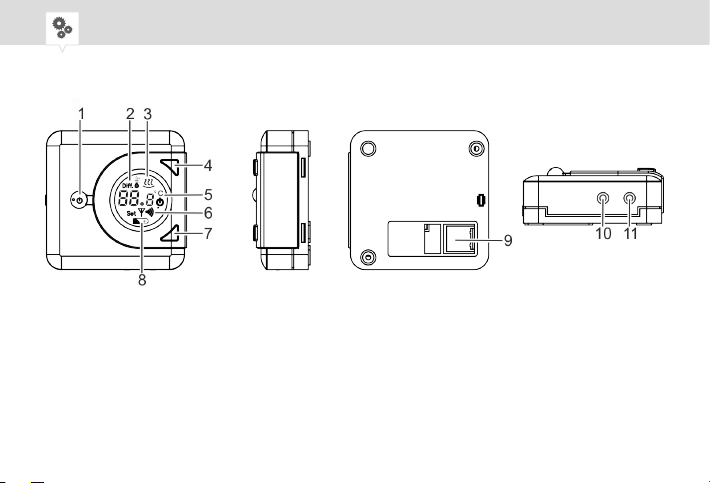
RAUMTHERMOSTAT (SENDER)
Abb. 1: Übersicht Raumthermostat
8
Page 9

1 Kipptaster
2 Schaltdifferenz-Symbol
3 Heizen-Symbol
4 Taste oben
5 Anzeige für Soll- und Ist-Temperatur
6 Funkverbindung
7 Taste unten
8 Batterie-Symbol
9 Kabeldurchführung
10 Reset-Taste
11 Funkverbindungstaste
DE
9
Page 10

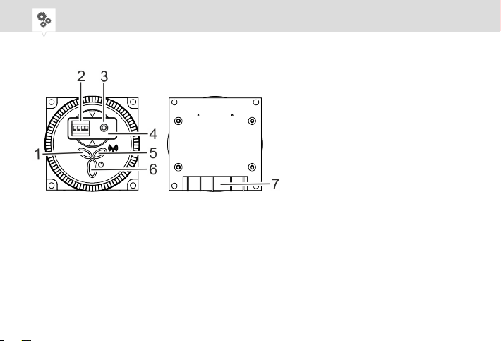
AKTOR (EMPFÄNGER)
Abb. 2: Übersicht Aktor (Empfänger) "RecFM/2"
1 LED EIN/AUS-System (blau)
2 DIP-Switch
3 Reset-Taste
4 Abdeckung für DIP-Switch
5 LED Funkverbindung (rot)
6 Manueller Handschalter (EIN/AUS)
7 Elektrischer Anschluss
10
Page 11

Sicherheit
Bestimmungsgemäße Verwendung
• Das Raumthermostat (Sender) dient ausschließlich der Regelung der Raumtemperatur und funktioniert nur in Kombination mit dem Aktor (Empfänger).
• Das Raumthermostat (Sender) und der Aktor (Empfänger) werden ausschließlich in geschlossenen
Räumen montiert und regeln die Raumtemperatur in einem Temperaturbereich von
+5 °C bis +35 °C.
Zur bestimmungsgemäßen Verwendung gehört auch die Einhaltung aller Angaben in dieser Anleitung.
Jede über die bestimmungsgemäße Verwendung hinausgehende oder andersartige Benutzung gilt als
Fehlgebrauch.
DE
11
Page 12

Restrisiken
WARNUNG!
Lebensgefahr durch elektrischen Schlag!
Unsachgemäße Montage und Installation des Geräts können zu lebensgefährlichen elektrischen Spannungen führen.
− Montage und Anschluss ausschließlich durch Elektrofachkraft durchführen lassen.
12
Page 13

Verletzungsgefahr bei falschem Umgang mit Batterien!
Bei falschem Umgang mit Batterien besteht die Gefahr, dass die Batterien
WARNUNG!
explodieren oder dass gesundheitsschädliche Flüssigkeit aus den Batterien
austritt.
− Niemals Batterien beschädigen oder deformieren.
− Niemals die Kontakte (Plus- und Minuspol) der Batterien kurzschließen.
− Batterien außerhalb der Reichweite von Kindern aufbewahren. Es
besteht Verschluckungsgefahr.
− Hautkontakt mit ausgelaufener Flüssigkeit vermeiden.
DE
13
Page 14

Installation
Aufstellort wählen
Aufstellort
Um eine fehlerfreie Messung des Raumthermostats zu gewährleisten, den Aufstellort richtig wählen.
Abb. 3: Anforderungen an den Aufstellort
14
Page 15

Raumthermostat (Sender)
MONTAGE AUF EINE UNTERPUTZDOSE
Personal:
• Elektrofachkraft
Montageplatte montieren
1. Die Montageplatte mit Schrauben (3,5 x 25 mm) auf die Unterputzdose montieren (Abb. 5).
Der Pfeil (Abb. 5/1) auf der Montageplatte muss nach oben zeigen.
Gehäusedeckel demontieren
2. Die Schraube am Gerätegehäuse mit dem Kreuzschlitzschraubendreher lösen und Gehäusedeckel
demontieren.
DE
15
Page 16

Batterie einlegen
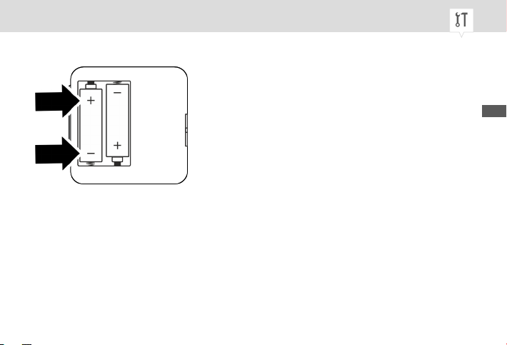
Abb. 4: Batterie einlegen
3. Die 2 Alkalibatterien vom Typ 1,5 V AA LR6 mit richtiger Polung (Abb. 4) in den Gehäusedeckel
einlegen.
16
Page 17

Gehäuseboden montieren
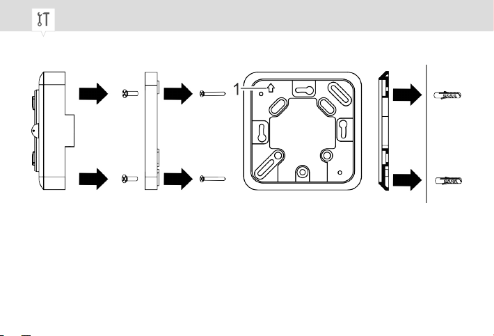
Abb. 5: Montage auf eine Unterputzdose und Aufputzmontage
Montage auf eine Unterputzdose ohne Dübel mit Montageplatte
Aufputzmontage ohne Montageplatte mit Dübel
4. Den Gehäuseboden des Geräts mit den Schrauben (3 x 6 mm) auf die Montageplatte montieren
(Abb. 5).
DE
17
Page 18

Gehäuse schließen
5. Den Gehäusedeckel auf den Gehäuseboden setzen und die Schraube am Gerätegehäuse mit dem
Kreuzschlitzschraubendreher festschrauben.
AUFPUTZMONTAGE
Personal:
• Elektrofachkraft
Gehäusedeckel demontieren
1. Die Schraube am Gerätegehäuse mit dem Kreuzschlitzschraubendreher lösen und den Gehäusedeckel demontieren.
2. Das Lochbild vom Gehäuseboden an die Wand übertragen und an den markierten Positionen Löcher
bohren (5-mm-Durchmesser und mindestens 25 mm tief).
3. Die mitgelieferten Wanddübel in die Löcher stecken.
Gehäuseboden montieren
4. Den Gehäuseboden mit den Schrauben (3,5 x 25 mm) an den Wanddübeln befestigen (Abb. 5).
18
Page 19

Batterie einlegen
5. Die 2 Alkalibatterien vom Typ 1,5 V AA LR6 mit richtiger Polung (Abb. 4) in den Gehäusedeckel
einlegen.
Gehäuse schließen
6. Den Gehäusedeckel auf den Gehäuseboden setzen und die Schraube am Gerätegehäuse mit dem
Kreuzschlitzschraubendreher festschrauben.
Die Montage des Geräts ist abgeschlossen.
ð
DE
19
Page 20

HYSTERESE EINSTELLEN
Auswahl der Hysterese
Beispiel
Die Hysterese kann zwischen ± 0,2 K, 0,4 K, 0,6 K, 0,8 K und 1 K (Werkseinstellung 0,4 K) (K =
Kelvin) eingestellt werden. Wenn die Hysterese z. B. 1 K beträgt und das Raumthermostat auf eine
Soll-Temperatur von 20 °C regeln soll, wird das Raumthermostat bei 19 °C eingeschaltet und bei 20
°C wieder ausgeschaltet.
Personal:
• Elektrofachkraft
1. Zum Einstellen der Hysterese die Taste oben (Abb. 1/4) und die Taste unten (Abb. 1/7) gleichzeitig
5 Sekunden gedrückt halten.
Die Anzeige für das Schaltdifferenz-Symbol (Abb. 1/2) leuchtet im Display auf.
ð
2. Die Taste oben (Abb. 1/4) drücken, um die Hysterese zu erhöhen, oder die Taste unten (Abb. 1/7)
drücken, um die Hysterese zu verringern.
20
Page 21

3. Wenn die Hysterese eingestellt ist, 5 Sekunden warten, bis das Schaltdifferenz-Symbol aufhört zu
blinken.
Das Raumthermostat regelt nun erst, sobald die Soll-Temperatur um die soeben eingestellte
ð
Hysterese unterschritten wird.
Aktor (Empfänger)
MONTAGE AN DEN BOILER
Personal:
• Elektrofachkraft
Am Boiler kann eine Blindplatte oder beispielsweise eine mechanische Zeitschaltuhr (Abb. 6) eingebaut sein.
DE
21
Page 22

Abb. 6: z.B. mechanische Zeitschaltuhr
22
Page 23

Aktor (Empfänger) montieren
Abb. 7: Aktor (Empfänger) montieren
1. Den Aktor (Empfänger) (Abb. 7/1) in die Montageplatte am Boiler einsetzen.
2. Die 4 Schrauben am Aktor (Empfänger) festdrehen (Abb. 7).
DE
23
Page 24

Anschließen
Abb. 8: Anschlussplan Aktor (Empfänger)
1 Neutralleiter
2 Phase
3 COM (Wechselkontakt, gemeinsamer Leiter Kontakt)
4 NC (Ruhekontakt, Öffner Kontakt)
5 NO (Arbeitskontakt, Schließer Kontakt)
3. Die Anschlusslaschen (Flach DIN 6,3) anhand des Anschlussplans (Abb. 8) in den entsprechenden
Kabelschuh einführen.
24
Page 25

Aktor (Empfänger) einbauen
Abb. 9: Aktor (Empfänger) einbauen
4. Den montierten Aktor (Empfänger) (Abb. 9/1) in den Boiler einbauen.
DE
25
Page 26

Funkverbindung
Funkverbindung vorbereiten
Abb. 10: Raumcode-Tabelle
26
Page 27

Das Raumthermostat (Sender) und der jeweilige Aktor (Empfänger) sind über ein Funksignal verbunden.
Damit sich Raumthermostat und Aktor finden, muss an beiden Geräten der gleiche Code (Raumcode)
eingestellt sein.
Am DIP-Switch des Aktors (Empfängers) kann kein Hauscode eingestellt werden, deshalb muss der
Hauscode am Raumthermostat auf Werkseinstellung 00 eingestellt sein, um eine Verbindung herzustellen.
Im Aktor (Empfänger) ist jeweils ein DIP-Switch verbaut. Dieser DIP-Switch verfügt über 4 Schalter und
kann auf maximal 16 verschiedenen Positionen geschaltet werden. Die Position der Schalter des DIPSwitchs hängt von dem gewünschten Raumcode ab. In der Raumcode-Tabelle (Abb. 10) wird der Raumcode mit der jeweiligen DIP-Switch-Position dargestellt.
Bei der Installation des Aktors (Empfängers) wird der Raumcode zwischen 00 und 16 frei gewählt und
der DIP-Switch wird in diese Position geschaltet.
DE
27
Page 28

Abb. 11: Raumcode einstellen
Die Verbindung zwischen Raumthermostat und Aktor kann nur aufgebaut werden, wenn der Raumcode
(Abb. 11/1) am Raumthermostat mit der DIP-Switch-Position im Empfänger übereinstimmt.
28
Page 29

Funkverbindung herstellen
Personal:
• Benutzer
Raumcode einstellen am Raumthermostat (Sender)
1. Die Funkverbindungstaste (Abb. 1/11) auf dem Gerät drücken.
Auf der Anzeige blinkt "00 H" (Abb. 1/5).
ð
Der Hauscode muss unverändert bleiben, sonst kann keine Verbindung zum Aktor (Empfänger) hergestellt werden.
2. Die Taste oben (Abb. 1/4) drücken, um den Wert zu erhöhen, oder die Taste unten (Abb. 1/7), um
den Wert zu verringern.
3. Die Funkverbindungstaste (Abb. 1/11), um den Hauscode zu speichern und zur nächsten Anzeige
zu gelangen.
Auf der Anzeige blinkt "01 r" (Abb. 11/5).
ð
DE
29
Page 30

Der am Raumthermostat einstellbare Raumcode liegt in einem Bereich von
00 – 16 und muss mit der DIP-Switch-Einstellung am Aktor übereinstimmen.
4. Die Taste oben (Abb. 1/4) drücken, um den Wert zu erhöhen, oder die Taste unten (Abb. 1/7), um
den Wert zu verringern.
5. Die Funkverbindungstaste (Abb. 1/11) drücken, um den Raumcode zu speichern, oder 5 Sekunden
warten, bis die Anzeige auf die Ist-Temperatur schaltet.
DIP-Switch einstellen am Aktor (Empfänger)
1. Die Abdeckung (Abb. 2/4) für DIP-Switch entfernen und den DIP-Switch (Abb. 2/2) einstellen.
ð
An Raumthermostat und an Aktor muss der gleiche Raumcode
eingestellt sein.
Für das Einstellen der DIP-Switch-Position die Raumcode-Tabelle beachten (Abb. 10).
2. Die Abdeckung (Abb. 2/4) für DIP-Switch wieder auflegen.
30
Page 31
Bedienung
Raumthermostat (Sender)
SOLL-TEMPERATUR EINSTELLEN
Personal:
• Benutzer
1. Den Kipptaster (Abb. 1/1) nach oben oder nach unten drücken, um das Heizsystem anzusteuern.
Der Kipptaster fällt auf die Ausgangsstellung zurück.
ð
2. Zum Einstellen der Soll-Temperatur die Taste oben (Abb. 1/4) oder die Taste unten (Abb. 1/7) 2 Mal
kurz nacheinander drücken.
3. Die Taste oben (Abb. 1/4) drücken, um die Soll-Temperatur zu erhöhen, oder die Taste unten
(Abb. 1/7) drücken, um die Soll-Temperatur zu verringern.
Die Soll-Temperatur wird bei jedem Drücken der Taste um 0,2 °C erhöht
oder verringert.
DE
31
Page 32
4. Wenn die Soll-Temperatur eingestellt ist, 5 Sekunden warten, bis der Sollwert aufhört zu blinken.
Das Gerät steuert das Heizsystem an und die Raumtemperatur wird auf die eingestellte Soll-
ð
Temperatur geregelt.
Das Einstellen der Soll-Temperatur auf einen höheren Wert
beschleunigt nicht das Aufheizen des Raums. Die Aufheizgeschwindigkeit wird ausschließlich durch die Bedingungen im
Heizsystem bestimmt.
RAUMTHERMOSTAT IN DEN STAND-BY-BETRIEB VERSETZEN
Personal:
• Benutzer
1. Den Kipptaster (Abb. 1/1) nach oben oder nach unten drücken, um das Gerät in den Stand-byBetrieb zu versetzen.
Der Kipptaster fällt in die Ausgangsstellung zurück.
ð
32
Page 33
Frostschutzfunktion
Das Gerät hält die Raumtemperatur auf + 5 °C. Das Heizsystem
wird automatisch eingeschaltet, wenn die Raumtemperatur unter
+ 5 °C sinkt.
Aktor (Empfänger) manuell bedienen
Personal:
• Benutzer
1.
Den manuellen Handschalter (Abb. 2/6) kurz drücken, um EIN/AUS zu schalten.
Die LED EIN/AUS-System leuchtet blau.
ð
Bei Störungen oder schlechter Funkverbindung kann über den manuellen Handschalter (Abb. 2/6) jederzeit EIN/AUS geschaltet werden.
Wenn nach 10 Minuten keine Funkverbindung aufgebaut wird, schaltet
der Schaltkontakt aus.
DE
33
Page 34
Systemzustand
LED-Anzeige
An den Farben der LEDs kann der Zustand des Aktors (Empfängers) abgelesen werden.
LED Farben Zustand des Aktors (Empfänger)
LED EIN/AUS-System (Abb. 2/1) leuchtet blau Verbraucher ist an.
LED EIN/AUS-System (Abb. 2/1) leuchtet nicht Verbraucher ist aus.
LED Funkverbindung (Abb. 2/5) blinkt rot Der Empfänger ist mit dem Sender ver-
LED Funkverbindung (Abb. 2/5) leuchtet rot Verbindung mit Sender ist fehlgeschlagen.
bunden.
34
Page 35
Entsorgung
Unsachgemäße Entsorgung
Gefahr für die Umwelt durch falsche Entsorgung!
Durch falsche Entsorgung können Gefahren für die Umwelt entstehen.
UMWELTSCHUTZ!
− Elektroschrott und Elektronikkomponenten fachgerecht entsorgen, d. h.
getrennt nach Materialgruppen der zu entsorgenden Teile.
− Batterien/Akkumulatoren (Richtlinie 2006/66/EG) und Elektro- oder Elektronikschrott keinesfalls mit dem Restmüll entsorgen. Im Zweifel Auskunft zur umweltgerechten Entsorgung bei den speziellen Entsorgungsfachbetrieben einholen.
− Grundsätzlich so umweltverträglich entsorgen, wie es dem Stand der
Umweltschutz-, Wiederaufbereitungs- und Entsorgungstechnik entspricht.
DE
35
Page 36

36
Page 37
This manual ensures safe and efficient use of the “thermio essential H rf” room thermostat (referred to
as “device” in the following). This manual is a component of the device and must remain accessible at
all times for everyone who uses the device.
This manual ensures safe and efficient use of the “RecFM/2 actuator” (referred to as “device” in the
following). This manual is a component of the device and must remain accessible at all times for
everyone who uses the device.
Everyone who uses the device must have read and understood this manual before commencing any
work. The basic prerequisite for working safely is compliance with all safety instructions and usage
instructions specified in this manual. Furthermore, the local accident prevention regulations and the
general safety regulations apply for the operating area of the device.
Copyright
This manual is copyright protected.
EN
37
Page 38
Handover of this manual to third parties, reproductions of any type and form – including excerpts – and
use and/or disclosure of the content without the written permission of Grässlin GmbH (referred to as
“manufacturer” in the following), except for internal purposes, is not permitted. Violations will result in
liability for compensation. The manufacturer reserves the right to assert additional claims.
The copyright is held by the manufacturer.
© Grässlin GmbH
Bundesstr. 36
78112 St. Georgen
GERMANY
Download
You can find the following information at
www.graesslin.de
:
• Declaration of conformity
• Download instructions
• Technical data
38
Page 39
Overview............................................................................................... 41
Design and function............................................................................................................ 41
Room thermostat (transmitter)...................................................................................... 42
Actuator (receiver)......................................................................................................... 44
Safety................................................................................................... 45
Installation............................................................................................ 47
Selecting an installation location......................................................................................... 47
Room thermostat (transmitter)............................................................................................ 48
Installation in a flush-mounted socket........................................................................... 48
On-wall mounting......................................................................................................... 51
Setting the hysteresis.................................................................................................... 53
Actuator (receiver).............................................................................................................. 54
Installation on the boiler................................................................................................ 54
Radio communication.......................................................................... 59
EN
39
Page 40
Preparing the radio communication..................................................................................... 59
Establishing radio communication....................................................................................... 62
Operation............................................................................................. 64
Room thermostat (transmitter)............................................................................................ 64
Setting the temperature setpoint................................................................................... 64
Putting the room thermostat into stand-by mode........................................................... 65
Manually operating the actuator (receiver).......................................................................... 66
System status...................................................................................... 67
LED display......................................................................................................................... 67
Disposal................................................................................................ 68
40
Page 41

Overview
Design and function
Description of function
The functions are only available if the room thermostat (transmitter) is connected to the actuator
(receiver). The room thermostat and the actuator may only be installed indoors and are used for regulating the room temperature in a temperature range from +5°C to +35°C.
If the room thermostat’s temperature sensor detects a drop in temperature, the heating system is
switched on and it is then switched off again once the temperature setpoint is reached.
The room thermostat can be connected to a maximum of 16 receivers. The transmitter is connected to
the receiver by a radio signal. The radio signal has a frequency of 868 MHz and a maximum range of 30
metres (depending on the premises).
EN
41
Page 42
ROOM THERMOSTAT (TRANSMITTER)
Fig. 1: Overview of room thermostat
42
Page 43

1 Toggle key
2 Switching differential symbol
3 Heating symbol
4 Top button
5 Display for setpoint and current temperature
6 Radio communication
7 Bottom button
8 Battery symbol
9 Cable feed-through
10 Reset button
11 Radio communication button
EN
43
Page 44
ACTUATOR (RECEIVER)
Fig. 2: Overview of actuator (receiver) “RecFM/2”
1 System ON/OFF LED (blue)
2 DIP switch
3 Reset button
4 Cover for DIP switch
5 Radio communication LED (red)
6 Manual switch (ON/OFF)
7 Electrical connection
44
Page 45
Safety
Intended use
• The room thermostat (transmitter) is used exclusively for regulating the room temperature and can
only function in combination with the actuator (receiver).
• The room thermostat (transmitter) and the actuator (receiver) may only be installed indoors and are
used for regulating the room temperature in a temperature range from +5°C to +35°C.
The intended use also includes compliance with all information specified in this manual. Any use other
than the intended use is considered incorrect use.
Residual risks
Danger to life due to electric shock!
Improper assembly and installation of the device can lead to life-threatening
WARNING!
electrical voltages.
− Have assembly and connection performed by a qualified electrician only.
EN
45
Page 46
Risk of injury if batteries are handled incorrectly!
Incorrect handling of batteries can result in a risk of batteries exploding or
WARNING!
harmful liquids escaping from the batteries.
− Never damage or deform batteries.
− Never short-circuit the contacts (plus and minus poles) of the batteries.
− Keep batteries out of the reach of children. There is a risk of swallowing.
− Avoid skin contact with escaped liquid.
46
Page 47
Installation
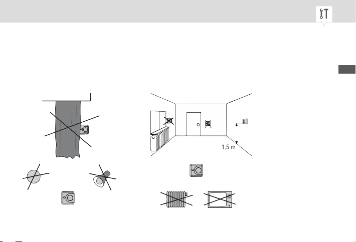
Selecting an installation location
Installation location
In order to ensure fault-free measurement by the room thermostat, choose the right installation location.
Fig. 3: Installation location requirements
EN
47
Page 48
Room thermostat (transmitter)
INSTALLATION IN A FLUSH-MOUNTED SOCKET
Personal:
• Qualified electrician
Installing the mounting plate
1. Attach the mounting plate to the flush-mounted socket with screws (3.5 x 25 mm) (Fig. 5).
The arrow (Fig. 5/1) on the mounting plate should point upwards.
Removing the housing cover
2. Undo the screw on the device housing with the Phillips screwdriver and remove the housing cover.
48
Page 49

Inserting the battery
Fig. 4: Inserting the battery
3. Insert the two alkaline batteries of type 1.5 V AA LR6 into the housing cover, ensuring the correct
polarity (Fig. 4).
EN
49
Page 50
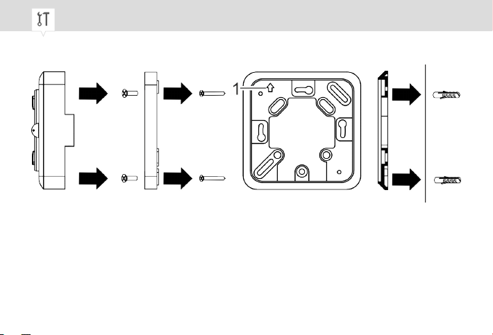
Installing the housing base
Fig. 5: Installation in a flush-mounted socket and on-wall mounting
Installation in a flush-mounted socket without wall-plugs and with mounting plate
On-wall mounting without mounting plate and with wall-plugs
4. Attach the housing base of the device to the mounting plate with the screws (3 x 6 mm) (Fig. 5).
50
Page 51
Closing the housing
5. Place the housing cover on the housing base and tighten the screw on the device housing with the
Phillips screwdriver.
ON-WALL MOUNTING
Personal:
• Qualified electrician
Removing the housing cover
1. Undo the screw on the device housing with the Phillips screwdriver and remove the housing cover.
2. Mark the hole pattern from the housing base onto the wall and drill holes at the points you marked
(5 mm diameter and at least 25 mm deep).
3. Insert the wall-plugs provided into the holes.
Installing the housing base
4. Fasten the housing base to the wall-plugs with the screws (3.5 x 25 mm) (Fig. 5).
EN
51
Page 52

Inserting the battery
5. Insert the two alkaline batteries of type 1.5 V AA LR6 into the housing cover, ensuring the correct
polarity (Fig. 4).
Closing the housing
6. Place the housing cover on the housing base and tighten the screw on the device housing with the
Phillips screwdriver.
The device is now fully installed.
ð
52
Page 53
SETTING THE HYSTERESIS
Selecting the hysteresis
Example
The hysteresis can be set between ± 0.2 K, 0.4 K, 0.6 K, 0.8 K and 1 K (factory setting 0.4 K) (K =
Kelvin). If, for example, the hysteresis is 1 K and the room thermostat is set to regulate to a temperature setpoint of 20°C, the room thermostat switches on at 19°C and switches off again at 20°C.
Personal:
• Qualified electrician
1. To set the hysteresis, press and hold both the top button (Fig. 1/4) and the bottom button (Fig. 1/7)
for five seconds.
The display for the switching differential symbol (Fig. 1/2) lights up on the display.
ð
2. Press the top button (Fig. 1/4) to increase the hysteresis or the bottom button (Fig. 1/7) to decrease
the hysteresis.
EN
53
Page 54
3. Once you have set the hysteresis, wait five seconds until the switching differential symbol stops
flashing.
The room thermostat only regulates once the temperature falls below the temperature set-
ð
point by the amount of the hysteresis that was just set.
Actuator (receiver)
INSTALLATION ON THE BOILER
Personal:
• Qualified electrician
A dummy plate or, for example, a mechanical timer (Fig. 6) can be installed
on the boiler.
54
Page 55
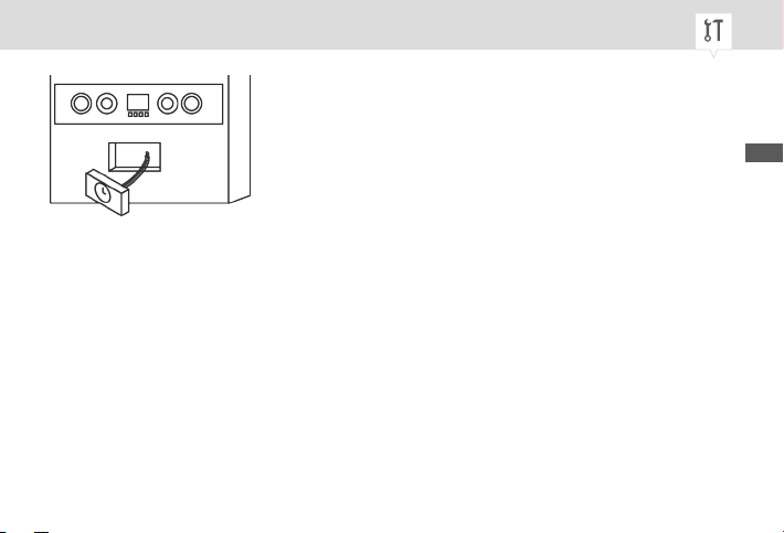
Fig. 6: E.g. mechanical timer
EN
55
Page 56
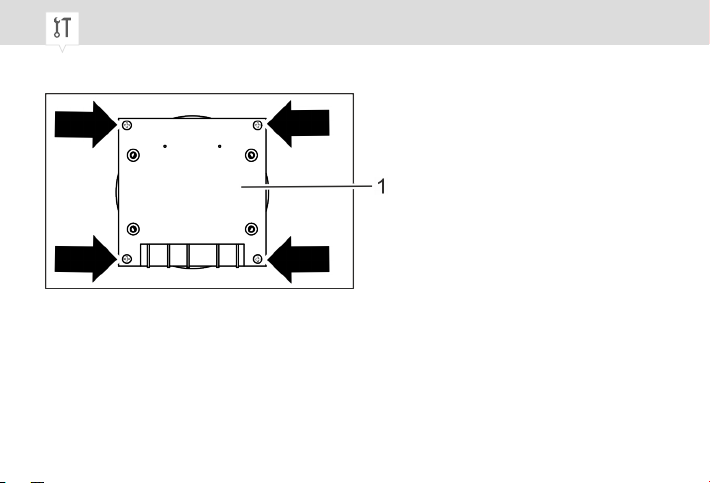
Assembling the actuator (receiver)
Fig. 7: Assembling the actuator (receiver)
1. Insert the actuator (receiver) (Fig. 7/1) in the mounting plate on the boiler.
2. Tighten the four screws on the actuator (receiver) (Fig. 7).
56
Page 57
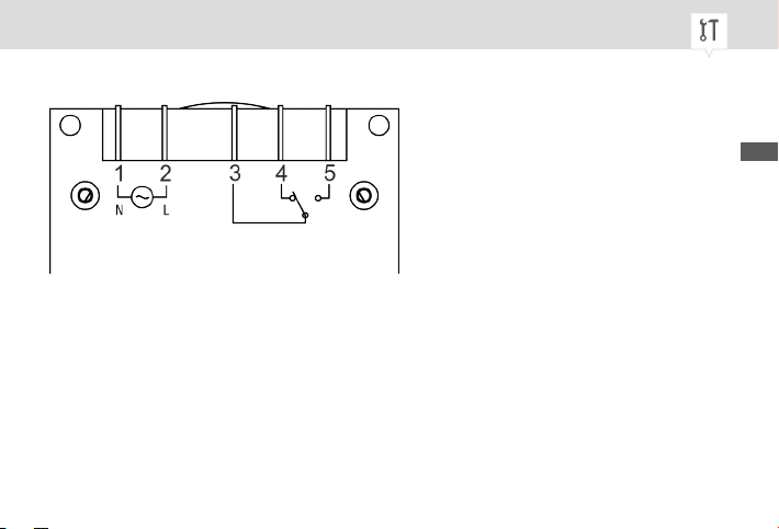
Connecting
Fig. 8: Wiring diagram for actuator (receiver)
1 Neutral conductor
2 Live conductor
3 COM (changeover contact, common conductor contact)
4 NC (normally closed contact)
5 NO (normally open contact)
3. Insert the connection lugs (flat, DIN 6.3) into the corresponding cable lugs in accordance with the
wiring diagram (Fig. 8).
EN
57
Page 58
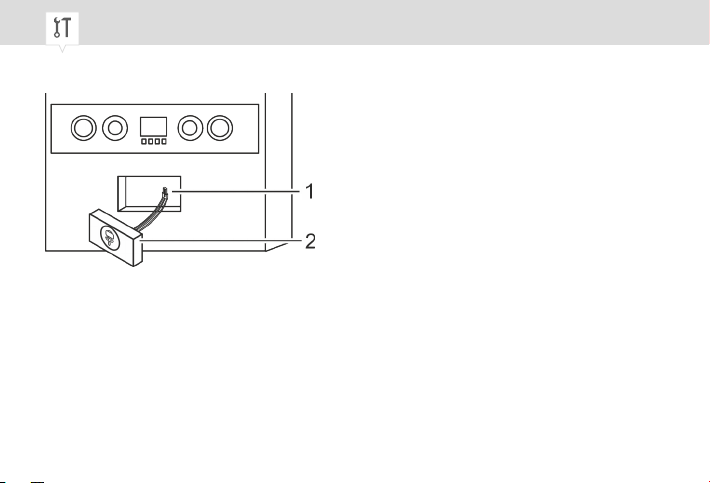
Installing the actuator (receiver)
Fig. 9: Installing the actuator (receiver)
4. Install the assembled actuator (receiver) (Fig. 9/1) in the boiler.
58
Page 59
Radio communication
Preparing the radio communication
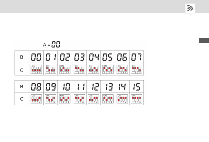
Fig. 10: Room code table
EN
59
Page 60
The room thermostat (transmitter) and each actuator (receiver) are connected by a radio signal. For the
room thermostat and actuator to identify each other, the same code (room code) must be set on both
devices.
You cannot set a house code on the DIP switch of the actuator (receiver), so the house code on the room
thermostat must be set to the factory setting of 00 to establish a connection.
One DIP switch is installed in each actuator (receiver). This DIP switch has 4 switches and can switch to
a maximum of 16 different positions. The position of the switch in the DIP switch depends on which
room code you want. The room code table (Fig. 10) shows the room code with the associated DIP switch
position.
When installing the actuator (receiver), you can freely select a room code between 00 and 16 and switch
the DIP switch to this position.
60
Page 61
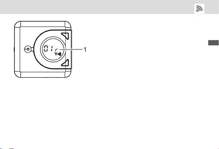
Fig. 11: Setting the room code
The connection between the room code and actuator can only be established if the room code
(Fig. 11/1) on the room thermostat matches the DIP switch position in the receiver.
EN
61
Page 62
Establishing radio communication
Personal:
• User
Setting the room code on the room thermostat (transmitter)
1. Press the radio communication button (Fig. 1/11) on the device.
“00 H” flashes on the display (Fig. 1/5).
ð
The house code must remain unchanged or it will not be possible
to establish a connection to the actuator (receiver).
2. Press the top button (Fig. 1/4) to increase the value or the bottom button (Fig. 1/7) to decrease the
value.
3. Press the radio communication button (Fig. 1/11) to save the house code and switch to the next
display.
“01 r” flashes on the display (Fig. 11/5).
ð
62
Page 63

The room code that can be set on the room thermostat is in the range 00 –
16 and must match the DIP switch setting on the actuator.
4. Press the top button (Fig. 1/4) to increase the value or the bottom button (Fig. 1/7) to decrease the
value.
5. Press the radio communication button (Fig. 1/11) to save the room code or wait five seconds until
the display switches to the current temperature.
Setting up the DIP switch on the actuator (receiver)
1. Remove the cover (Fig. 2/4) of the DIP switch and set the DIP switch (Fig. 2/2).
ð
The same room code must be set on the room thermostat and the
actuator.
When setting the DIP switch position, note the room code table (Fig. 10).
2. Replace the cover (Fig. 2/4) of the DIP switch.
EN
63
Page 64
Operation
Room thermostat (transmitter)
SETTING THE TEMPERATURE SETPOINT
Personal:
• User
1. Press the toggle key (Fig. 1/1) up or down to activate the heating system.
The toggle key returns to its starting position.
ð
2. To set the temperature setpoint, press either the top button (Fig. 1/4) or the bottom button (Fig. 1/7)
twice in quick succession.
3. Press the top button (Fig. 1/4) to increase the temperature setpoint or the bottom button (Fig. 1/7)
to decrease the temperature setpoint.
The temperature setpoint is increased or decreased by 0.2°C each time
you press a button.
64
Page 65
4. Once you have set the temperature setpoint, wait five seconds until the setpoint stops flashing.
The device activates the heating system and the room temperature is adjusted to the tem-
ð
perature setpoint.
Setting the temperature setpoint to a higher value does not make
the room heat up more quickly. The heating rate is determined by
the conditions in the heating system only.
PUTTING THE ROOM THERMOSTAT INTO STAND-BY MODE
Personal:
• User
1. Press the toggle key (Fig. 1/1) up or down to put the device in stand-by mode.
The toggle key returns to its starting position.
ð
EN
65
Page 66
Frost protection function
The device keeps the room temperature at +5°C. The heating
system is automatically switched on if the room temperature
drops below +5°C.
Manually operating the actuator (receiver)
Personal:
• User
1.
Press the manual switch (Fig. 2/6) briefly to switch ON/OFF.
The system ON/OFF LED lights up blue.
ð
66
In the event of faults or poor radio communication, you can switch the
device ON/OFF at any time using the manual switch (Fig. 2/6). If no radio
communication is established after 10 minutes, the switching contact
switches off.
Page 67
System status
LED display
The colours of the LEDs indicate the status of the actuator (receiver).
LED Colours Status of actuator (receiver)
System ON/OFF LED (Fig. 2/1) Lit up blue Consumer is on.
System ON/OFF LED (Fig. 2/1) Not lit up Consumer is off.
Radio communication LED
(Fig. 2/5)
Radio communication LED
(Fig. 2/5)
Flashing red The receiver is connected to the transmitter.
Lit up red Connection to transmitter failed.
EN
67
Page 68
Disposal
Improper disposal
ENVIRONMENT!
Incorrect disposal presents an environmental danger.
Incorrect disposal could result in environmental dangers.
− Electric scrap and electronic components must be disposed of correctly,
i.e. the parts for disposal must be sorted into material groups.
− Batteries/rechargeable batteries (Directive 2006/66/EC) and electrical or
electronic scrap must under no circumstances be disposed of with general waste. If in doubt, please obtain information about environmentally
responsible disposal from specialist disposal companies.
− Disposal must be environmentally responsible and must comply with the
current status of environmental protection, recycling and disposal technology.
68
Page 69
Cette notice permet une utilisation sûre et efficace du thermostat d'ambiance « thermio essential H rf »
(ci-après « appareil »). Cette notice est partie intégrante de l'appareil et doit être conservée dans un
endroit accessible en permanence à toute personne utilisant l'appareil.
Cette notice permet une utilisation sûre et efficace de l'actionneur RecFM/2 (ci-après « appareil »). Cette
notice est partie intégrante de l'appareil et doit être conservée dans un endroit accessible en permanence à toute personne utilisant l'appareil.
Cette notice doit être attentivement lue et comprise par toute personne utilisant l'appareil avant le début
de tout travail. Le respect de toutes les consignes de sécurité et instructions de manipulation indiquées
dans cette notice est une condition fondamentale d'un travail sécurisé. En outre, les prescriptions
locales de prévention des accidents et les dispositions générales de sécurité s'appliquent au domaine
d'utilisation de l'appareil.
Protection du droit d'auteur
Cette notice est protégée par le droit d'auteur.
FR
69
Page 70
La cession de cette notice à un tiers, les reproductions de tout type et sous toute forme – y compris
d'extraits – ainsi que l'utilisation et/ou la communication du contenu sont interdites sans autorisation
écrite de Grässlin GmbH (ci après « fabricant ») sauf pour un usage interne. Toute infraction sera sanctionnée par des dommages et intérêts. Le fabricant se réserve le droit de faire valoir d'autres prétentions.
Le fabricant est propriétaire du droit d'auteur.
© Grässlin GmbH
Bundesstr. 36
78112 St. Georgen
ALLEMAGNE
Téléchargement
Les informations suivantes sont disponibles sur
www.graesslin.de
:
• Déclaration de conformité
• Notice à télécharger
• Caractéristiques techniques
70
Page 71
Vue d'ensemble................................................................................... 73
Structure et fonctionnement................................................................................................ 73
Thermostat d'ambiance (émetteur)............................................................................... 74
Actionneur (récepteur)................................................................................................... 76
Sécurité................................................................................................ 77
Installation............................................................................................ 79
Choix du lieu de montage.................................................................................................... 79
Thermostat d'ambiance (émetteur)..................................................................................... 80
Montage dans une boîte encastrée................................................................................ 80
Montage en saillie......................................................................................................... 83
Réglage de l'hystérésis................................................................................................. 85
Actionneur (récepteur)........................................................................................................ 86
Montage sur le ballon d'eau chaude.............................................................................. 86
Connexion radio................................................................................... 91
FR
71
Page 72
Préparation de la connexion radio....................................................................................... 91
Établissement de la connexion radio................................................................................... 94
Utilisation............................................................................................. 96
Thermostat d'ambiance (émetteur)..................................................................................... 96
Réglage de la température de consigne........................................................................ 96
Mise en mode veille du thermostat d'ambiance............................................................. 98
Commande manuelle de l'actionneur (récepteur)................................................................ 99
État du système................................................................................. 100
Affichage à LED................................................................................................................ 100
Élimination.......................................................................................... 101
72
Page 73

Vue d'ensemble
Structure et fonctionnement
Description du fonctionnement
La fonctionnalité n'est possible que si le thermostat d'ambiance (émetteur) est connecté à l'actionneur
(récepteur). Le thermostat d'ambiance et l'actionneur ne sont montés que dans des locaux fermés et
régulent dans une plage de température de +5 °C à +35 °C.
Lorsque le thermostat d'ambiance détecte une chute de température au moyen de la sonde de température, le système de chauffage est activé, puis, lorsque la température de consigne est atteinte, à nouveau désactivé.
Le thermostat d'ambiance peut être connecté à 16 récepteurs max. L'émetteur est connecté au récepteur via un signal radio. La fréquence du signal radio est de 868 MHz et dispose d'une portée de 30
mètres max. (en fonction des locaux).
FR
73
Page 74
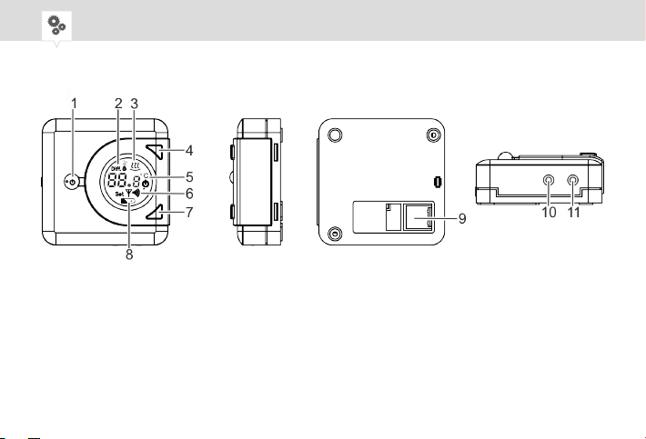
THERMOSTAT D'AMBIANCE (ÉMETTEUR)
Fig. 1: Vue d'ensemble du thermostat d'ambiance
74
Page 75

1 Interrupteur à bascule
2 Symbole de la différence de commutation
3 Symbole de chauffage
4 Touche haut
5 Affichage de la température de consigne et de la température actuelle
6 Connexion radio
7 Touche bas
8 Symbole de pile
9 Passe-câble
10 Touche de réinitialisation
11 Touche de connexion radio
FR
75
Page 76

ACTIONNEUR (RÉCEPTEUR)
Fig. 2: Vue d'ensemble de l'actionneur (récepteur) « RecFM/2 »
1 LED système MARCHE/ARRÊT (bleu)
2 Commutateur DIP
3 Touche de réinitialisation
4 Cache pour commutateur DIP
5 LED connexion radio (rouge)
6 Interrupteur manuel (MARCHE/ARRÊT)
7 Raccordement électrique
76
Page 77
Sécurité
Utilisation conforme
• Le thermostat d'ambiance (émetteur) sert exclusivement à réguler la température ambiante et ne
fonctionne qu'en combinaison avec l'actionneur (récepteur).
• Le thermostat d'ambiance (émetteur) et l'actionneur (récepteur) ne sont montés que dans des
locaux fermés et régulent la température ambiante dans une plage de température de
+5 °C à +35 °C.
Le respect de toutes les consignes de cette notice est essentiel à une utilisation conforme. Toute utilisation sortant du cadre de l'utilisation conforme ou différente de celle-ci est considérée comme une utilisation non conforme.
FR
77
Page 78
Risques résiduels
AVERTISSEMENT !
AVERTISSEMENT !
Danger de mort par électrocution !
Un montage et une installation non conformes de l'appareil peuvent provoquer des tensions électriques mortelles.
− Seul un électricien est habilité à effectuer le montage et le raccordement.
Risque de blessures en cas de manipulation incorrecte des piles !
En cas de manipulation incorrecte des piles, les piles risquent d'exploser ou
un liquide toxique risque de s'écouler des piles.
− Ne jamais endommager ou déformer les piles.
− Ne jamais court-circuiter les contacts (pôles positif et négatif) des piles.
− Conserver les piles hors de portée des enfants. Risque d'ingestion.
− Éviter de toucher le liquide écoulé.
78
Page 79
Installation
Choix du lieu de montage
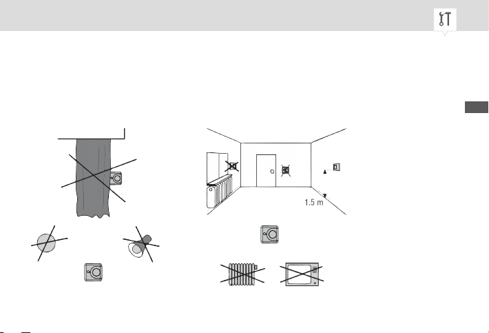
Lieu de montage
Choisir avec soin le lieu de montage pour ne pas fausser les mesures du thermostat d'ambiance.
Fig. 3: Exigences relatives au lieu de montage
FR
79
Page 80
Thermostat d'ambiance (émetteur)
MONTAGE DANS UNE BOÎTE ENCASTRÉE
Personal:
• Électricien
Montage de la plaque de montage
1. Monter la plaque de montage avec les vis (3,5 x 25 mm) sur la boîte encastrée (Fig. 5).
La flèche (Fig. 5/1) sur la plaque de montage doit pointer vers le haut.
Démontage du couvercle du boîtier
2. Desserrer la vis sur le boîtier de l'appareil avec le tournevis cruciforme et démonter le couvercle du
boîtier.
80
Page 81
Insertion des piles
Fig. 4: Insertion des piles
3. Insérer les 2 piles alcalines de type 1,5 V AA LR6 dans le couvercle du boîtier en respectant la
polarité (Fig. 4).
FR
81
Page 82
Montage du socle du boîtier
Fig. 5: Montage dans une boîte encastrée et montage en saillie
Montage dans une boîte encastrée sans chevilles avec plaque de montage
Montage en saillie sans plaque de montage avec chevilles
4. Monter le socle du boîtier de l'appareil sur la plaque de montage à l'aide des vis (3 x 6 mm) (Fig. 5).
82
Page 83
Fermeture du boîtier
5. Placer le couvercle du boîtier sur le socle du boîtier et visser à fond la vis sur le boîtier de l'appareil
avec le tournevis cruciforme.
MONTAGE EN SAILLIE
Personal:
• Électricien
Démontage du couvercle du boîtier
1. Desserrer la vis sur le boîtier de l'appareil avec le tournevis cruciforme et démonter le couvercle du
boîtier.
2. Reporter le gabarit des trous du socle du boîtier sur le mur et percer les trous aux positions marquées (diamètre 5 mm et profondeur 25 mm minimum).
3. Insérer les chevilles fournies dans les trous.
Montage du socle du boîtier
4. Fixer le socle du boîtier aux chevilles à l'aide des vis (3,5 x 25 mm) (Fig. 5).
FR
83
Page 84

Insertion des piles
5. Insérer les 2 piles alcalines de type 1,5 V AA LR6 dans le couvercle du boîtier en respectant la
polarité (Fig. 4).
Fermeture du boîtier
6. Placer le couvercle du boîtier sur le socle du boîtier et visser à fond la vis sur le boîtier de l'appareil
avec le tournevis cruciforme.
Le montage de l'appareil est terminé.
ð
84
Page 85
RÉGLAGE DE L'HYSTÉRÉSIS
Sélection de l'hystérésis
Exemple
L'hystérésis peut être réglée entre ± 0,2 K, 0,4 K, 0,6 K, 0,8 K et 1 K (réglage d'usine 0,4 K) (K =
Kelvin). Si l'hystérésis est de 1 K p. ex. et que le thermostat d'ambiance doit réguler à une température de consigne de 20 °C, le thermostat d'ambiance est activé à 19 °C et désactivé à nouveau à 20
°C.
Personal:
• Électricien
1. Maintenir appuyées simultanément la touche haut (Fig. 1/4) et la touche bas (Fig. 1/7) pendant 5
secondes pour régler l'hystérésis.
Le symbole de la différence de commutation (Fig. 1/2) s'affiche à l'écran.
ð
2. Appuyer sur la touche haut (Fig. 1/4) pour augmenter l'hystérésis ou sur la touche bas (Fig. 1/7)
pour réduire l'hystérésis.
FR
85
Page 86
3. Lorsque l'hystérésis est réglée, attendre 5 secondes jusqu'à ce que le symbole de la différence de
commutation cesse de clignoter.
Le thermostat d'ambiance ne commence à réguler que lorsque la température actuelle est
ð
inférieure à la température de consigne moins l'hystérésis réglée.
Actionneur (récepteur)
MONTAGE SUR LE BALLON D'EAU CHAUDE
Personal:
• Électricien
Il est possible de monter un cache ou une minuterie mécanique (Fig. 6) sur le
ballon d'eau chaude.
86
Page 87
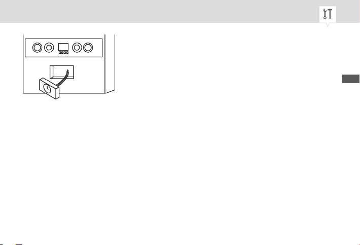
Fig. 6: p. ex. minuterie mécanique
FR
87
Page 88
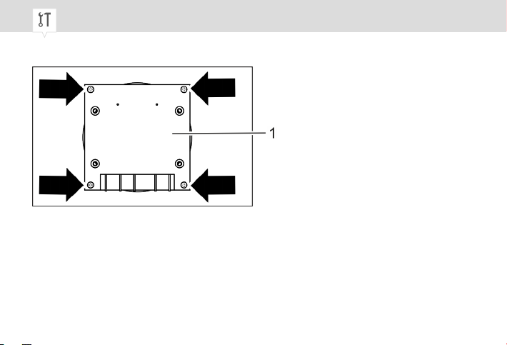
Montage de l'actionneur (récepteur)
Fig. 7: Montage de l'actionneur (récepteur)
1. Placer l'actionneur (récepteur) (Fig. 7/1) dans la plaque de montage sur le ballon d'eau chaude.
2. Visser à fond les 4 vis sur l'actionneur (récepteur) (Fig. 7).
88
Page 89
Raccordement
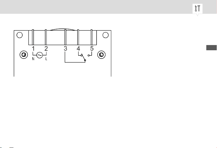
Fig. 8: Schéma de raccordement de l'actionneur (récepteur)
1 Conducteur neutre
2 Phase
3 COM (contact inverseur, contact conducteur commun)
4 NC (contact rupteur, contact normalement fermé)
5 NO (contact de travail, contact normalement ouvert)
3. Insérer les languettes de raccordement (plates DIN 6,3) dans les cosses de câble correspondantes
au moyen du schéma de raccordement (Fig. 8).
FR
89
Page 90
Montage de l'actionneur (récepteur)
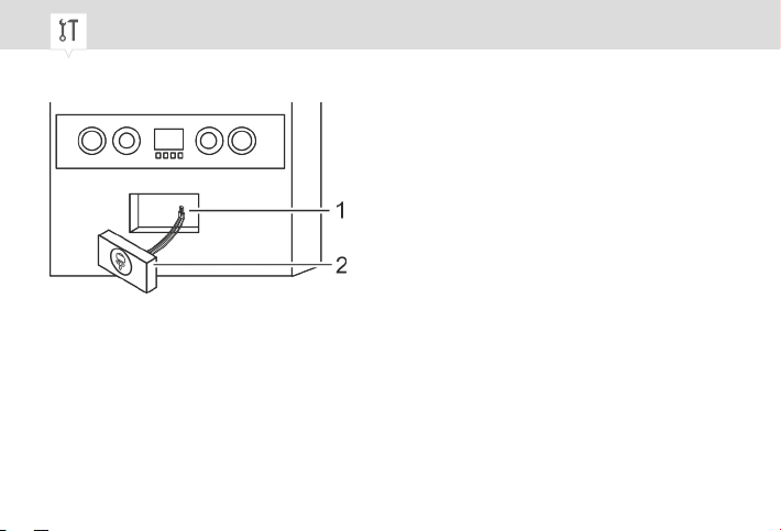
Fig. 9: Montage de l'actionneur (récepteur)
4. Installer l'actionneur monté (récepteur) (Fig. 9/1) dans le ballon d'eau chaude.
90
Page 91
Connexion radio
Préparation de la connexion radio
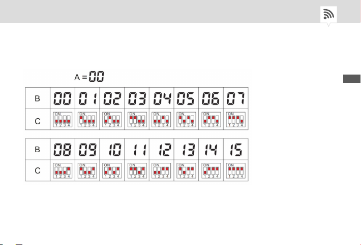
Fig. 10: Tableau des codes des locaux
FR
91
Page 92
Le thermostat d'ambiance (émetteur) et l'actionneur correspondant (récepteur) sont connectés par un
signal radio. Afin que le thermostat d'ambiance et l'actionneur se trouvent, il faut régler le même code
(code du local) sur les deux appareils.
Il n'est pas possible de régler le code de la maison sur le commutateur DIP de l'actionneur (récepteur), il
faut donc régler le code de la maison sur le thermostat d'ambiance avec le réglage d'usine 00 pour
établir une connexion.
Chaque actionneur (récepteur) comporte un commutateur DIP. Ce commutateur DIP dispose de 4 interrupteurs et peut être commuté sur 16 positions différentes maximum. La position des interrupteurs du
commutateur DIP dépend du code du local souhaité. Le code du local et la position correspondante du
commutateur DIP sont représentés dans le tableau des codes de locaux (Fig. 10).
Lors de l'installation de l'actionneur (récepteur), le code du local est choisi librement entre 00 et 16 et le
commutateur DIP est commuté dans cette position.
92
Page 93
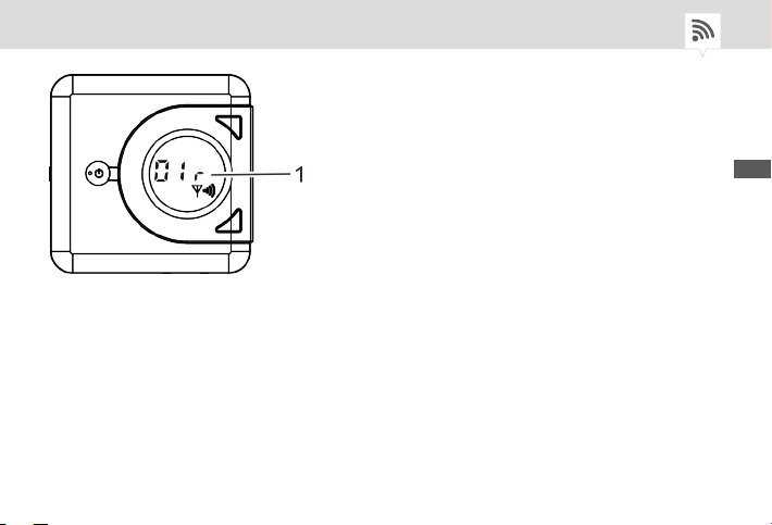
Fig. 11: Réglage du code du local
La connexion entre le thermostat d'ambiance et l'actionneur ne peut être établie que si le code du local
(Fig. 11/1) sur le thermostat d'ambiance correspond à la position du commutateur DIP dans le récepteur.
FR
93
Page 94
Établissement de la connexion radio
Personal:
• Utilisateur
Réglage du code du local sur le thermostat d'ambiance (émetteur)
1. Appuyer sur la touche de connexion radio (Fig. 1/11) de l'appareil.
« 00 H » clignote sur l'affichage (Fig. 1/5).
ð
Le code de la maison doit rester inchangé sans quoi il ne sera pas
possible d'établir une connexion avec l'actionneur (récepteur).
2. Appuyer sur la touche haut (Fig. 1/4) pour augmenter la valeur ou sur la touche bas (Fig. 1/7) pour
réduire la valeur.
3. Appuyer sur la touche de connexion radio (Fig. 1/11) pour enregistrer le code de la maison et
accéder au prochain affichage.
« 01 r » clignote sur l'affichage (Fig. 11/5).
ð
94
Page 95
Le code du local réglable sur le thermostat d'ambiance est compris entre 00
et 16 et doit correspondre au réglage du commutateur DIP sur l'actionneur.
4. Appuyer sur la touche haut (Fig. 1/4) pour augmenter la valeur ou sur la touche bas (Fig. 1/7) pour
réduire la valeur.
5. Appuyer sur la touche de connexion radio (Fig. 1/11) pour enregistrer le code du local ou attendre 5
secondes jusqu'à ce que l'affichage passe à la température actuelle.
Réglage du commutateur DIP sur l'actionneur (récepteur)
1. Retirer le cache (Fig. 2/4) du commutateur DIP et régler le commutateur DIP (Fig. 2/2).
ð
Le même code de local doit être réglé sur le thermostat d'ambiance et sur l'actionneur.
Pour le réglage de la position du commutateur DIP, se référer au tableau des codes des
locaux (Fig. 10).
2. Remettre en place le cache (Fig. 2/4) du commutateur DIP.
FR
95
Page 96

Utilisation
Thermostat d'ambiance (émetteur)
RÉGLAGE DE LA TEMPÉRATURE DE CONSIGNE
Personal:
• Utilisateur
1. Appuyer sur l'interrupteur à bascule (Fig. 1/1) vers le haut ou vers le bas pour activer le système de
chauffage.
L'interrupteur à bascule revient en position initiale.
ð
2. Appuyer 2 fois rapidement sur la touche haut (Fig. 1/4) ou la touche bas (Fig. 1/7) pour régler la
température de consigne.
3. Appuyer sur la touche haut (Fig. 1/4) pour augmenter la température de consigne ou sur la touche
bas (Fig. 1/7) pour réduire la température de consigne.
96
Page 97
La température de consigne est augmentée ou réduite de 0,2 °C à
chaque pression de touche.
4. Lorsque la température de consigne est réglée, attendre 5 secondes jusqu'à ce que la valeur de
consigne cesse de clignoter.
L'appareil active le système de chauffage et la température ambiante est régulée selon la
ð
température de consigne réglée.
Le réglage de la température de consigne sur une valeur supérieure n'accélère pas le réchauffement du local. La vitesse de
réchauffement ne dépend que des conditions dans le système de
chauffage.
FR
97
Page 98
MISE EN MODE VEILLE DU THERMOSTAT D'AMBIANCE
Personal:
• Utilisateur
1. Appuyer sur l'interrupteur à bascule (Fig. 1/1) vers le haut ou vers le bas pour mettre l'appareil en
mode veille.
L'interrupteur à bascule revient en position initiale.
ð
Fonction antigel
L'appareil maintient la température ambiante à + 5 °C. Le système de chauffage est automatique activé lorsque la température
ambiante passe en dessous de + 5 °C.
98
Page 99
Commande manuelle de l'actionneur (récepteur)
Personal:
• Utilisateur
1.
Appuyer brièvement sur l'interrupteur manuel (Fig. 2/6) pour commuter sur MARCHE/ARRÊT.
La LED de système MARCHE/ARRÊT s'allume en bleu.
ð
En cas d'interférences ou de mauvaise connexion radio, il est possible
d'effectuer à tout moment une commutation sur MARCHE/ARRÊT au
moyen de l'interrupteur manuel (Fig. 2/6). Si aucune connexion radio
n'est établie au bout de 10 minutes, le contact de commutation de commande est désactivé.
FR
99
Page 100
État du système
Affichage à LED
L'état de l'actionneur (récepteur) peut être lu au moyen des couleurs des LED.
LED Couleurs État de l'actionneur (récepteur)
LED du système MARCHE/ARRÊT
(Fig. 2/1)
LED du système MARCHE/ARRÊT
(Fig. 2/1)
LED de connexion radio (Fig. 2/5) clignote en rouge Le récepteur est connecté à l'émetteur.
LED de connexion radio (Fig. 2/5) s'allume en rouge Échec de la connexion avec l'émetteur.
s'allume en bleu Le consommateur est allumé.
ne s'allume pas Le consommateur est éteint.
100
 Loading...