

Page 1
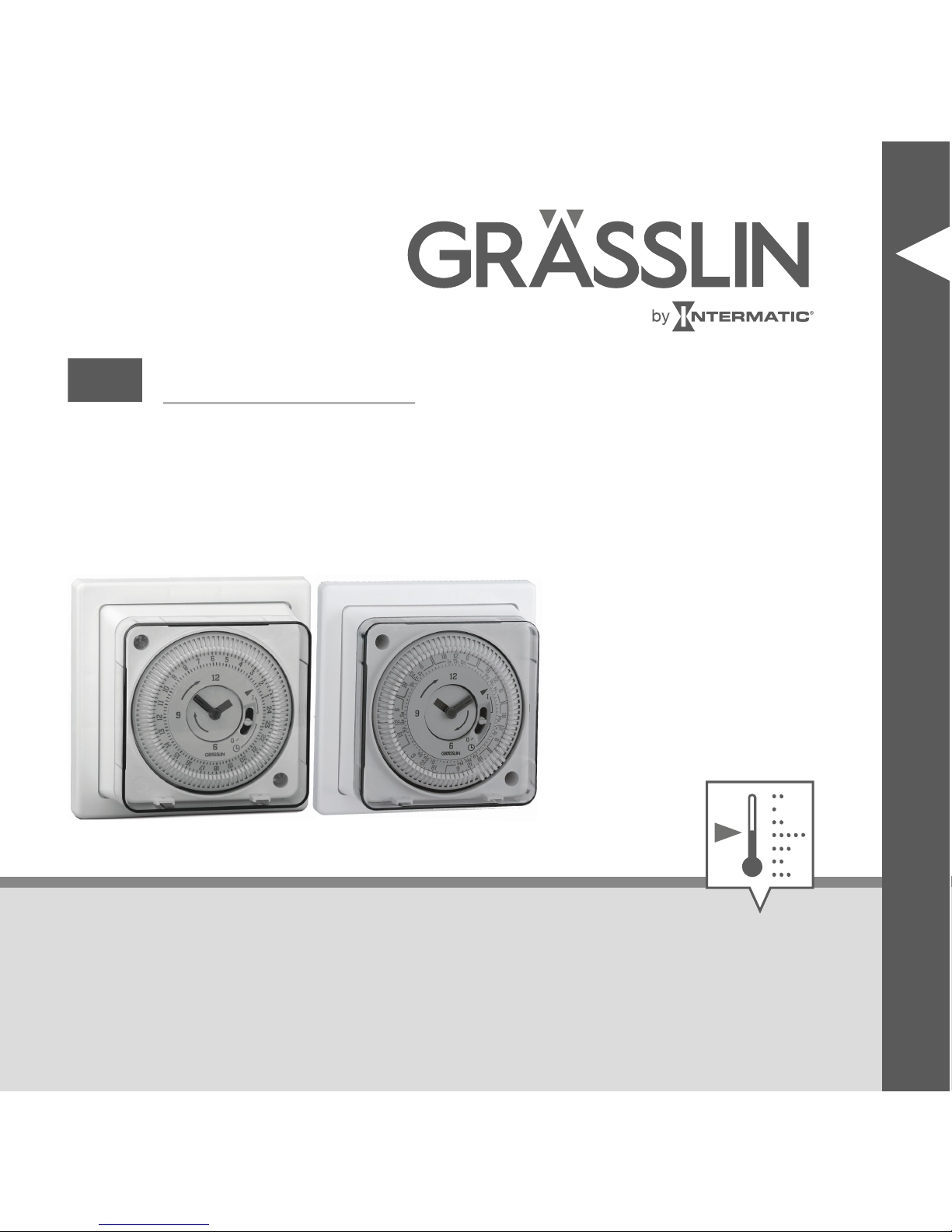
thermio™ eco BG1S, BG7S
and BG1Q
EN
Operating manual
Page 2

This manual ensures safe and efficient use of the timers
“thermio™ eco BG1S”, “thermio™ eco BG7S” and
“thermio™ eco BG1Q” (referred to as “device” in the following). This manual is a component of the devices and
must remain accessible at all times for everyone who
uses the devices.
2
Page 3

Everyone who uses the devices must have read and
understood this manual before commencing any work.
The basic prerequisite for working safely is compliance
with all safety instructions and usage instructions specified in this manual. Furthermore, the local accident prevention regulations and the general safety regulations in
the area in which the devices are operated apply.
Illustrations in this manual are intended to provide a general understanding and may differ from the actual
design.
Copyright
This manual is copyright protected.
EN
3
Page 4

Handover of this manual to third parties, reproductions of
any type and form – including excerpts – and use and/or
disclosure of the content without the written permission
of Grässlin GmbH (referred to as “manufacturer” in the
following), except for internal purposes, is not permitted.
Violations will result in liability for compensation. The
manufacturer reserves the right to assert additional
claims.
The copyright is held by the manufacturer.
© Grässlin GmbH
Bundesstr. 36
78112 St. Georgen
GERMANY
4
Page 5

Declaration of conformity and download instructions
The declaration of conformity for the devices described in
this manual, a download of the manual, and the technical
data can be found at
www.graesslin.de
.
EN
5
Page 6
Overview................................................ 7
Safety................................................... 14
Installation............................................ 17
Operation............................................. 33
Setting the day of the week/time................ 33
Setting the on/off time................................ 38
Selecting the operating mode..................... 40
Disposal............................................... 42
6
Page 7

Overview
Fig. 1: Front view
EN
7
Page 8

1 Dial with tappets
2 Manual switch (ON, OFF, automatic mode)
3 Screw connection
4 “thermio™ BG7S” timer
5 “thermio™ BG1S und BG1Q” timer
Description of function
The “thermio™ eco BG1S” and “thermio™ eco BG7S”
timers are analogue single-channel synchronous timers
and the “thermio™ eco BG1Q” is an analogue singlechannel quartz timer.
The “thermio™ BG1S” and “thermio™ eco BG1Q” times
can switch connected loads with a smallest possible
switching time of 15 minutes.
8
Page 9

The “thermio™ BG7S” timer can switch a connected
load on each day with a smallest possible switching time
of 2 hours.
EN
9
Page 10

Manual switch
The timers have a manual switch; this can switch
between the modes (automatic), 0 (OFF) and I (ON).
10
Page 11
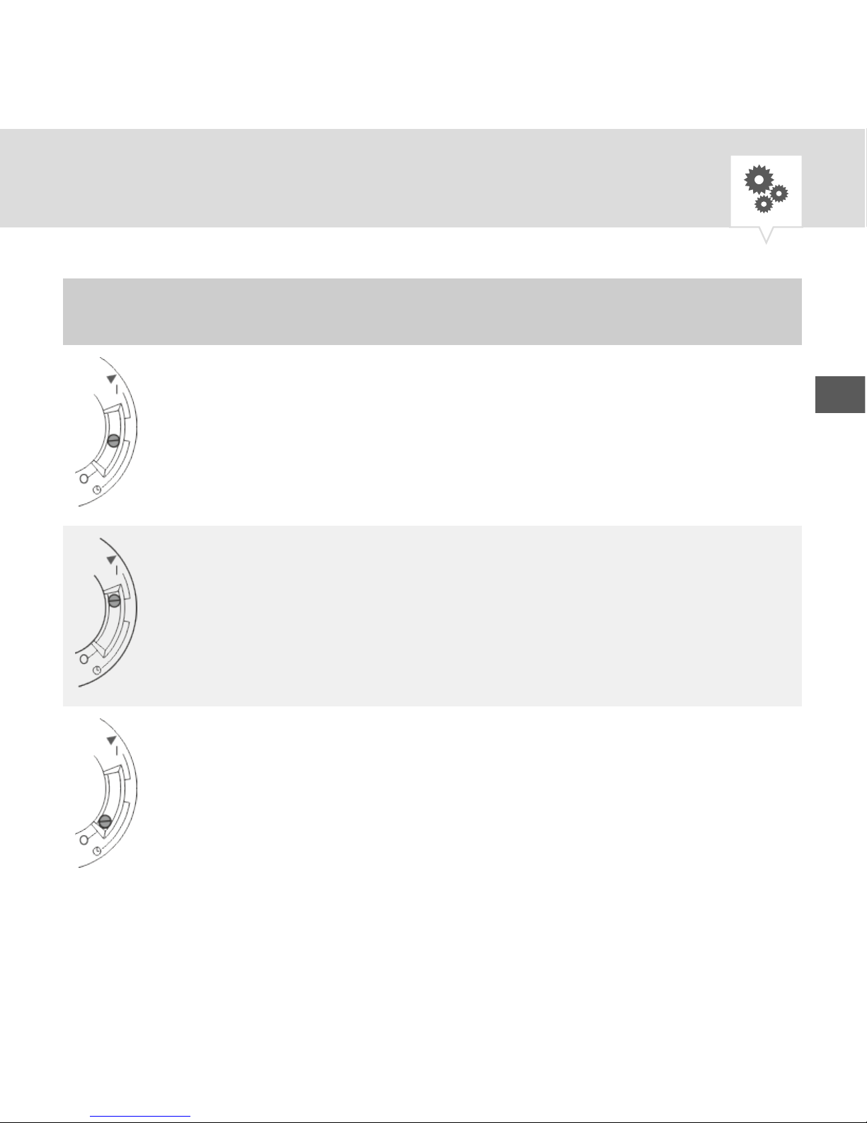
Position Function
Automatic mode
Permanently on
Permanently off
EN
11
Page 12

Power reserve
The “thermio™ eco BG1Q” timer has a built-in,
rechargeable battery. In the event of a power failure, the
device saves the programmed settings for a maximum of
72 hours.
The battery is charged during normal operation and does
not have to be replaced.
12
Page 13

Contents
The following components are included in the contents:
Number Designation
1 “thermio™ eco BG1S”, “thermio™ eco
BG7S” or “thermio™ eco BG1Q”
4 Wire end sleeves
EN
13
Page 14

Safety
Intended use
The timers are used exclusively for switching heating
systems, pumps, motors and machines with a resistance
load of 16 A and for switching individual immersion
heaters up to 3 kW. The connected devices must comply
with the limits specified in the technical data.
The “thermio™ eco BG1S” and “thermio™ eco BG7S”
timers may only be used in private and commercial areas
at ambient temperatures from -20 °C to +85 °C.
The “thermio™ eco BG1Q” timer may only be used in
private and commercial areas at ambient temperatures
from -20 °C to +55 °C.
14
Page 15
The intended use also includes compliance with all information specified in this manual. Any use other than the
intended use is considered incorrect use.
Residual risks
WARNING!
Danger to life due to electric shock!
Improper assembly and installation of the
device may result in life-threatening electrical
voltages.
− Have assembly and connection performed
by a qualified electrician only.
EN
15
Page 16

WARNING!
Danger due to insufficient wire cross-section!
If wires with an insufficiently large cross-section are used, short circuits or fires may occur.
− For the flexible wires, only use terminals
with a maximum cross-section of
2.5 mm².
16
Page 17

Installation
The device is installed on a mounting socket (BS 4662 or
BS 5733). This mounting socket can be installed either
as a flush-mounted socket in the wall or it is installed on
the wall.
EN
17
Page 18
In general, the following instructions apply to
all three models. Where there are differences,
the corresponding model number is specified
before the instructions.
Personnel:
• Qualified electrician
Special tool:
• Flat-head screwdriver
• Phillips screwdriver
• Crimping pliers for wire end sleeves
Materials:
18
Page 19
• Wire end sleeves (4 pieces)
Installing the housing base
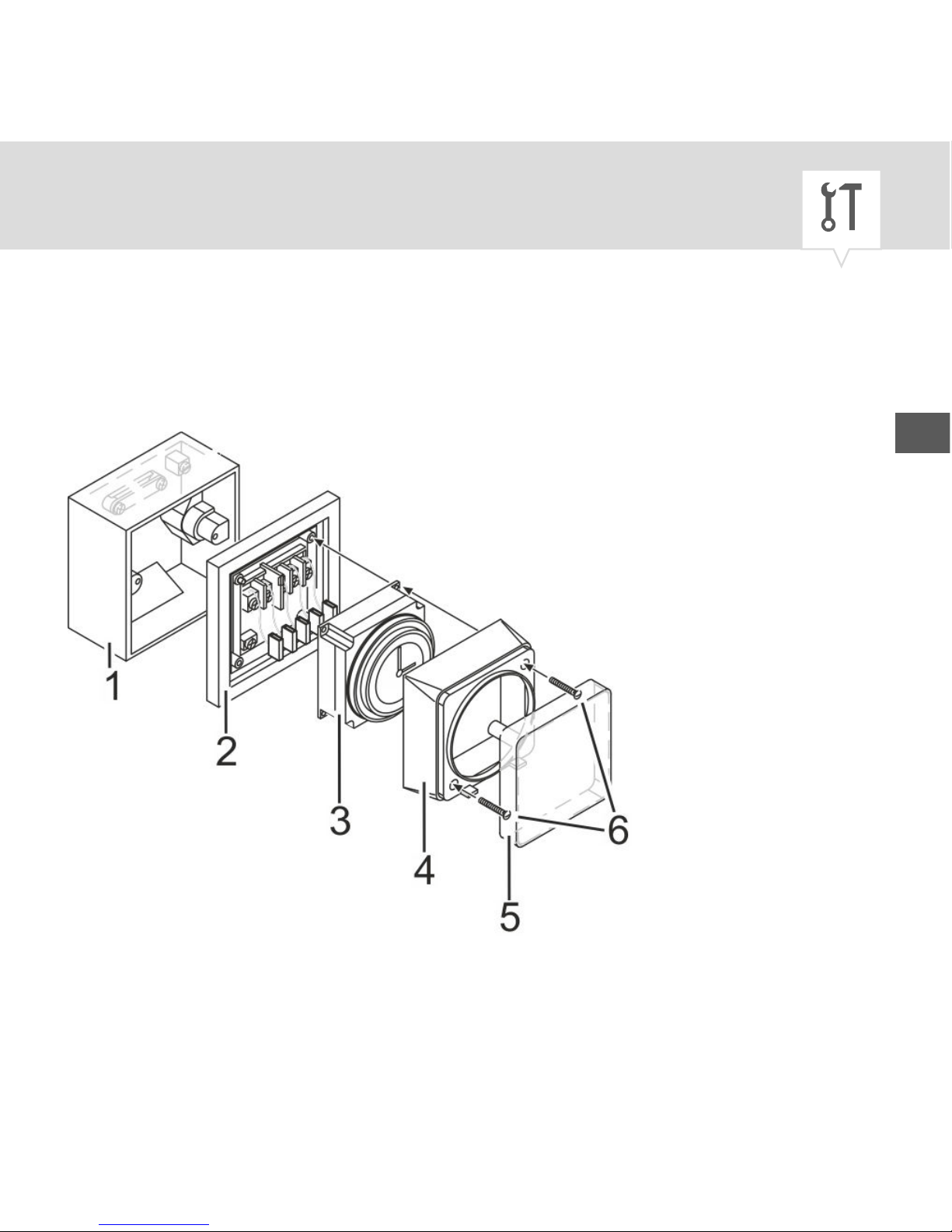
Fig. 2: Installation on a mounting socket (Fig. 2/1)
EN
19
Page 20
1 Mounting socket
(BS4662 or
BS5733)
2 Housing base
3 Dial
4 Housing cover
5 Plastic cover
6 Screws
1. Remove the plastic cover (Fig. 2/5).
2. Undo the screws (Fig. 2/6) on the housing cover
(Fig. 2/4) using a flat-head screwdriver.
3.
The dial is connected to the housing base
by blue connection wires.
20
Page 21

NOTICE!
Danger of material damage!
When the dial is lifted up, the connection
wires may be damaged.
− Lift up the dial carefully.
− Do not remove the dial from the
housing base.
Remove the housing cover (Fig. 2/4) and the dial
together with the connected housing base (Fig. 2/3).
4. Install the housing base (Fig. 2/2) on the mounting
socket (Fig. 2/1).
EN
21
Page 22

Preparing the electrical connection
5. Strip the insulation from the connection wire.
• Stripping length: 8 mm
6. Insert the wire end sleeves onto the connection
wires.
7. Crimp the wire end sleeves using the crimping
pliers.
22
Page 23
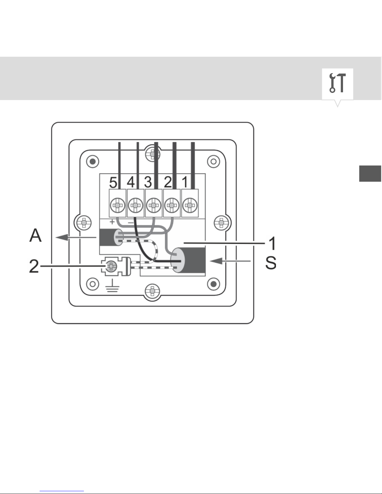
Fig. 3: BG1S/BG7S housing base
8. Thread the connection wires into the device through
the cable feed-through (Fig. 3/1).
EN
23
Page 24
Electric connections
9.
To ensure that the wiring is correct, consult the operating manual for the heating
system in use.
The devices have protection class 1, so
earthing is essential. Connect the earth
correctly.
Insert the earth connection wire into the earth contact (Fig. 3/2).
24
Page 25
BG1S/BG7S mains connection
The diagram (Fig. 4) shows the wiring for
mains connection. The connection between
terminals 3 and 5 must be mounted.
For low-voltage, connect connections L
(230 V) or N to 5 or 4, respectively, and apply
the electric circuit to connections 3 and 2.
EN
25
Page 26
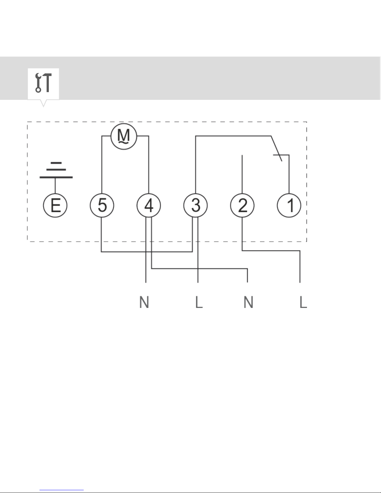
Fig. 4: BG1S/BG7S mains connection
26
Page 27
10. Insert the connection wires into the corresponding
terminals in accordance with the relevant wiring
diagram (A = application/connected load; S = supply
voltage; N = neutral conductor; L = live conductor)
(Fig. 4).
BG1S/BG7S voltage-free connection
If there is no connection between terminals 3
and 5, it is possible to control the connected
loads in a separate circuit with different voltages up to 250 V AC.
To do so, connect connections L or N to 5 or 4,
respectively, and apply L
(in)
or L
(out)
to connec-
tion 2 or 3, respectively.
EN
27
Page 28
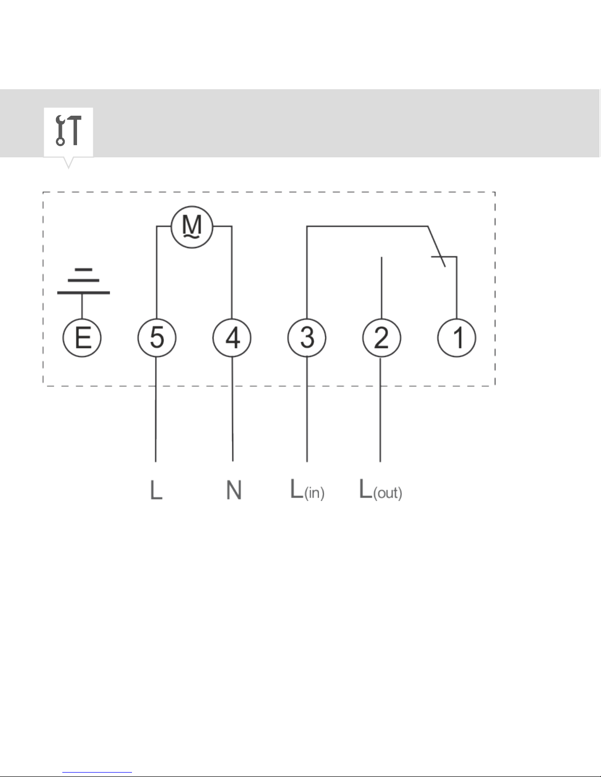
Fig. 5: BG1S/BG7S voltage-free connection
28
Page 29

11. Insert the connection wires into the corresponding
terminals in accordance with the relevant wiring
diagram (A = application/connected load; S = supply
voltage; N = neutral conductor; L = live conductor)
(Fig. 5).
EN
29
Page 30
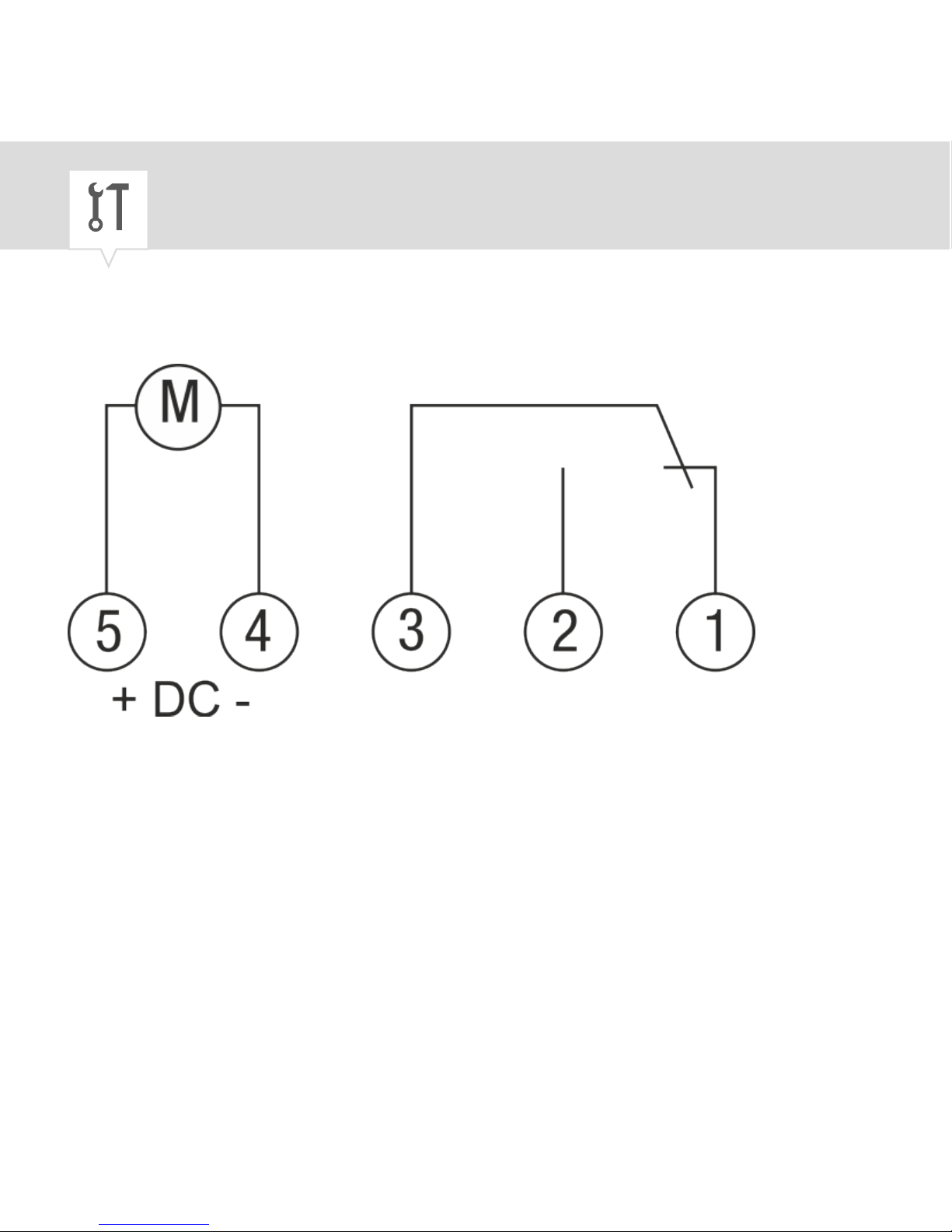
BG1Q circuit diagram
Fig. 6: BG1Q circuit diagram
30
Page 31

12. Insert the connection wires into the corresponding
terminals in accordance with the relevant wiring
diagram (A = application/connected load; S = supply
voltage; N = neutral conductor; L = live conductor)
(Fig. 6).
13.
NOTICE!
Tightening torques
To avoid damage and faulty contacts,
tighten the terminals using a torque of
0.75 Nm.
Tighten all terminals using a Phillips screwdriver.
EN
31
Page 32

Closing the housing
NOTICE!
Danger of material damage to the wires!
When closing the housing, there is a risk of
pinching wires. This results in material
damage to the wires and faulty contacts.
− Make sure that the wires are not pinched
when the you close the housing.
14. Screw the dial (Fig. 2/3) and housing cover (Fig. 2/4)
onto the housing base (Fig. 2/2) using a flat-head
screwdriver.
15. Replace the plastic cover (Fig. 2/5).
32
Page 33
Operation
Setting the day of the week/time
With the “thermio™ BG7S”" timer (Fig. 7/6)
the day of the week (Monday – Sunday) and
the current time have to be set. With the
“thermio™ BG1S” and “thermio™ eco BG1Q”
(Fig. 7/5) timers only the current time has to
be set.
Personnel:
• User
EN
33
Page 34
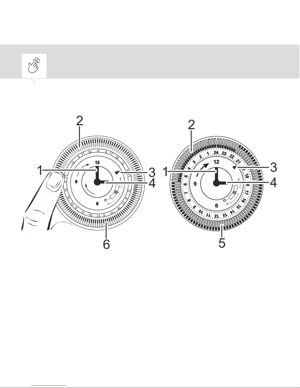
Setting the day of the week
Fig. 7: Setting the day of the week and the time
1 Minute hand
2 Dial with tappets
3 Indicator marker
4 Hour hand
34
Page 35

5 “thermio™ BG1S
und BG1Q” timer
6 “thermio™ BG7S”
timer
1.
NOTICE!
Risk of material damage due to turning
anti-clockwise!
Turning the dial or the clock hand anticlockwise can result in material damage
to the timer.
− Make sure to turn the dial and clock
hand clockwise only.
EN
35
Page 36

“thermio™ BG7S” only: To set the current day of
the week, rotate the dial (Fig. 7/2) clockwise until
the indicator marker (Fig. 7/3) points to the current
day of the week.
Setting the time
2. To roughly set the time, turn the dial (Fig. 7/2)
clockwise until the indicator marker points to the
current time.
36
Page 37
In 12 hour display: 6:00 = 6.00 (a.m.) and
16:00 = 4.00 (p.m.)
The timer does not distinguish between
summer and winter time. As a result, you
have to set the summer and winter time
manually by adjusting the current time.
3. To finely adjust the time, turn the minute hand
(Fig. 7/1) clockwise until the time indicated by the
indicator marker (Fig. 7/3) matches the current time.
ð
The dial and the clock hand rotate together
with the current time.
EN
37
Page 38
Setting the on/off time
Personnel:
• User
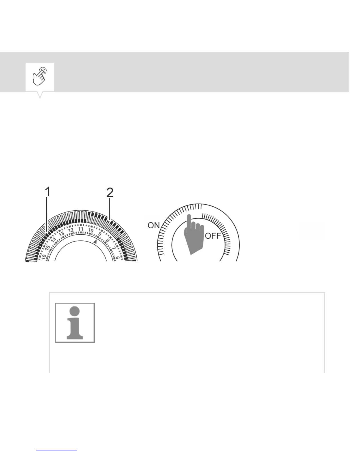
Fig. 8: Setting the tappets
1.
With the “thermio™ BG1S” and
“thermio™ eco BG1Q” timers, each
tappet corresponds to 15 minutes of
switching time.
38
Page 39

With the “thermio™ BG7S” timer, each
tappet corresponds to 2 hours of
switching time.
If the tappets are pushed inwards, the
heating system is switched off during that
time; if the tappets are pushed outwards,
the heating system is switched on during
that time.
Push the tappets to OFF (Fig. 8/1) or ON (Fig. 8/2),
according to your desired switching times.
2. To activate the timer, switch the manual switch to
the position
.
EN
39
Page 40

Selecting the operating mode
In addition to automatic mode, which switches according
to the defined switching times, the device can also be
switched permanently on or off.
Personnel:
• User
1. Switch the manual switch to the desired position.
ð
The device reacts according to the position.
40
Page 41
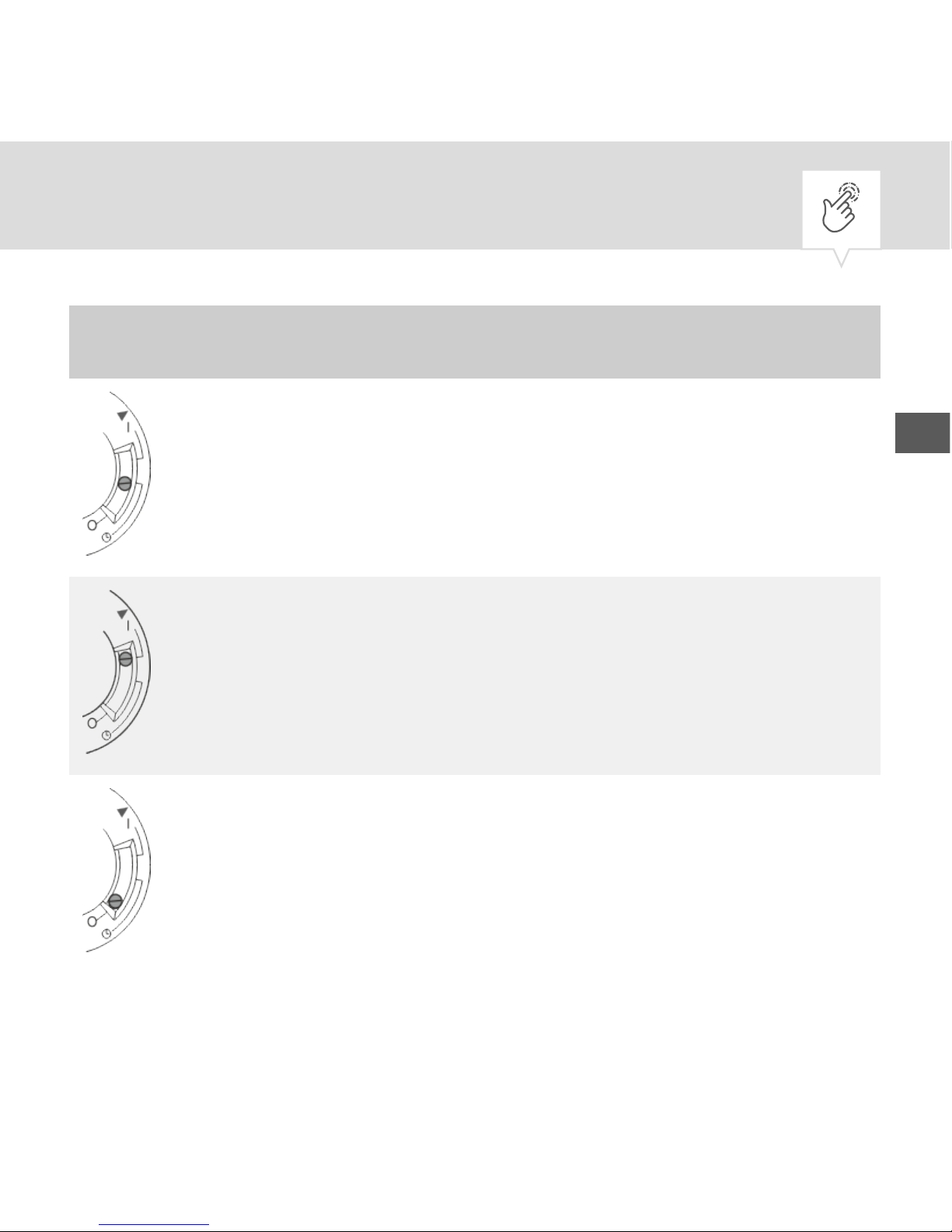
Position Function
Automatic mode
Permanently on
Permanently off
EN
41
Page 42

Disposal
ENVIRONMENT!
Environmental hazard!
Incorrect disposal could result in environmental dangers.
− Electric scrap and electronic components
must be disposed of correctly, i.e. the
parts for disposal must be sorted into
material groups.
42
Page 43

− Batteries/rechargeable batteries (Directive
2006/66/EC) and electrical or electronic
scrap must under no circumstances be
disposed of with general waste. If in
doubt, please obtain information about
environmentally responsible disposal from
specialist disposal companies.
− Disposal must be environmentally responsible and must employ state-of-the-art
environmental protection, recycling and
disposal technology.
EN
43
Page 44

80.10.1480.7/0217/V01
Grässlin GmbH
Bundesstrasse 36
78112 St. Georgen
GERMANY
Telephone: +49 7724 933-0
Fax: +49 7724 933-240
www.graesslin.de
 Loading...