

Page 1

GL840
USER’S MANUAL
MANUAL NO.GL840-UM-153
Find Quality Products Online at: [email protected]
www.GlobalTestSupply.com
Page 2
To Ensure Safe and Correct Use
To Ensure Safe and Correct Use
To ensure safe and correct use of the GL840, read this manual thoroughly before use.
•
After having read this manual, keep it in a handy location for quick reference as needed.
•
Do not permit small children to touch the GL840.
•
The following describes important points for safe operation. Please be sure to observe them strictly.
•
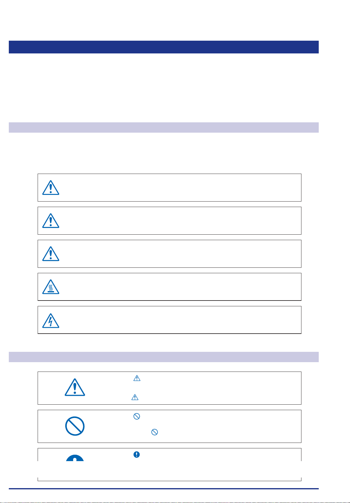
Conventions Used in This Manual
To promote safe and accurate use of the GL840 as well as to prevent human injury and property damage,
safety precautions provided in this manual are ranked into the ve categories described below. Be sure you
understand the difference between each of the categories.
This category provides information that, if ignored, is
DANGER
highly likely to cause fatal or serious injury to the operator.
WARNING
CAUTION
HIGH
TEMPERATURE
ELECTRICAL
SHOCK
Description of Safety Symbols
The symbol indicates information that requires careful
attention (including warnings). The specic point requiring
attention is described by an illustration or text within or next to
the symbol.
This category provides information that, if ignored, is
likely to cause fatal or serious injury to the operator.
This category provides information that, if ignored, could
cause physical damage to the GL840.
This category provides information that, if ignored, is
likely to cause burns or other injury to the operator due to
contact with high temperature.
This category provides information that, if ignored, is
likely to expose the operator to electrical shock.
The symbol indicates an action that is prohibited. Such
prohibited action is described by an illustration or text within or
next to the symbol.
The symbol indicates an action that must be performed.
Such imperative action is described by an illustration or text
www.GlobalTestSupply.com
Find Quality Products Online at: [email protected]
within or next to the symbol.
i
Page 3
Safety Precautions
Safety Precautions
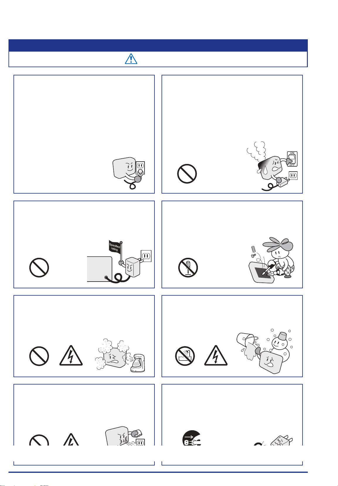
WARNING
Be sure to securely connect the GL840's GND
terminal.
After checking that the power switch is turned off, connect
•
the power cord’s female plug to the GL840 and then
connect its male plug into the electrical socket.
For grounding, use a ground wire with a diameter of at least
•
0.75 mm2. When using the GL840 in an environment where
grounding is not
possible, ensure measured is no greater than 50 V (DC or
rms).
Before turning on the GL840, ensure that the electric
socket’s supply voltage conforms to the GL840’s
power rating.
Use of a different supply voltage may cause damage to the
•
GL840 or a fire hazard due to electrical
shock or current leakage.
If the GL840 generates smoke, is too hot, emits a
strange odor, or otherwise functions abnormally,
turn off its power and unplug its power cord from the
electrical socket.
Use of the GL840 in such status may result in a fire hazard
•
or electrical shock.
After checking that smoke is no longer being generated,
•
contact your sales representative or nearest Graphtec
vendor to request repair.
Never try to perform repair yourself.
•
Repair work by inexperienced
personnel is extremely dangerous.
Use prohibited
Never disassemble or remodel the GL840.
Such action may cause a fire hazard due to electric shock
•
or current leakage.
Contact with a high-voltage component inside the GL840
•
may cause electric shock.
If repair is required, contact your
•
sales representative or nearest
Graphtec vendor.
Use prohibited No disassembly
Avoid using the GL840 in extremely dusty or humid
places.
Such use may cause a fire hazard due to electrical shock or
•
current leakage.
Use prohibited
Prevent dust or metallic matter from adhering to the
power supply connector.
Adhesion of foreign matter may cause a fire hazard due to
•
electrical shock or current leakage.
Watch out for
electrical shock
Avoid using the GL840 in places where it may be
exposed to water such as bathrooms, locations
exposed to wind and rain, and so on.
An electrical shock or fire may be caused due to current
•
leakage.
Avoid water
Never use a damaged power cord.
Use of a damaged cord may result in a fire hazard due to
•
electrical shock.
If the cord becomes damaged, order a new one to replace
•
it.
Watch out for
electrical shock
Find Quality Products Online at: [email protected]
Use prohibited
Watch out for
electrical shock
www.GlobalTestSupply.com
Unplug the power
cord from the socket
ii
Page 4
Safety Precautions
Safety Precautions
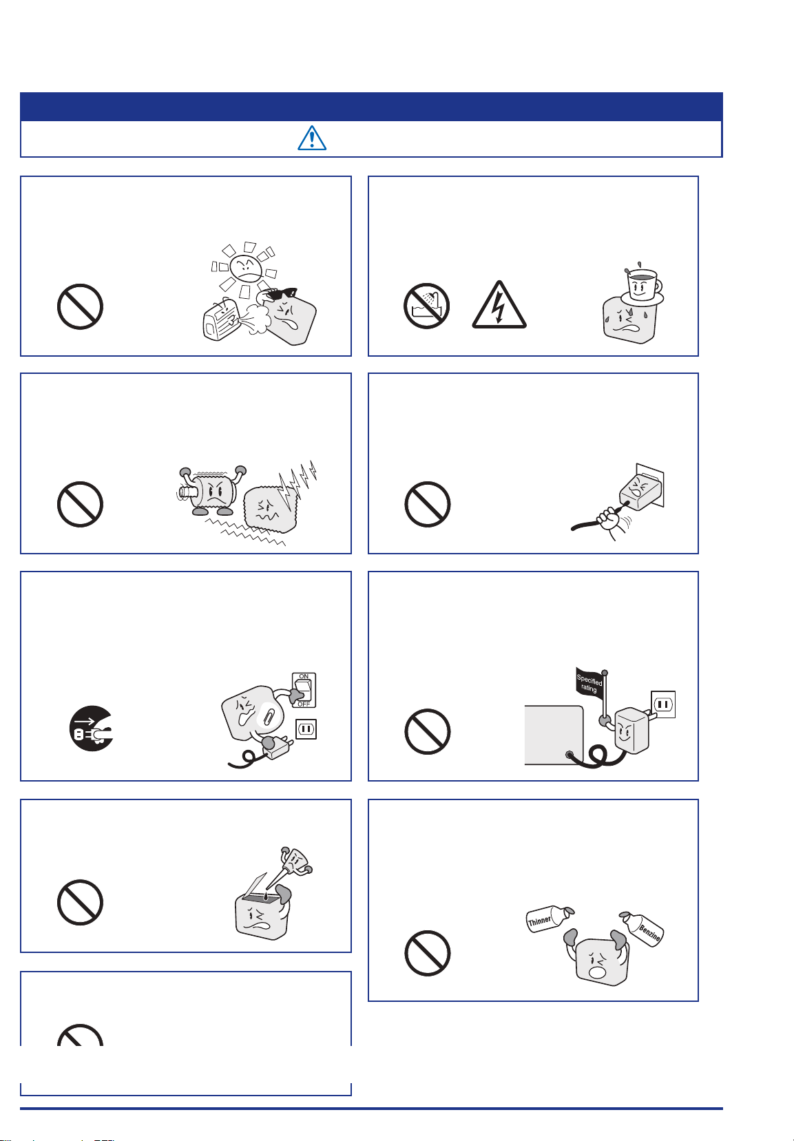
CAUTION
Do not use or store the GL840 in a location exposed to
direct sunlight or the direct draft of an air conditioner
or heater.
Such location may impair the
•
GL840’s performance.
Use prohibited
Do not use the GL840 in a location subject to
excessive mechanical vibration or electrical noise.
Such location may impair the GL840’s performance.
•
Use prohibited Use prohibited
If uid or foreign matters enters inside the GL840,
turn off the power switch and disconnect the power
cord from the electrical socket.
Use in such status may cause a fire hazard due to electrical
•
shock or current leakage.
Contact your sales representative or
•
nearest Graphtec vendor to request
repair.
Do not place the receptacles containing uid onto this
device or close to this device.
Fluid spilling inside the GL840 may cause a fire hazard due
•
to electrical shock or current leakage.
To insert or disconnect the power cord or a signal
input cable, grasp the power cord’s plug or the signal
input cable’s connector.
Pulling the cord/cable itself damages the cord/cable,
•
resulting in a fire hazard or electrical shock.
Do not use the AC power supply and the DC power
supply other than the specied supply voltage for this
device.
Such action may cause a fire hazard due to electric shock
•
or current leakage.
Avoid water
Watch out for
electrical shock
Unplug the power
cord from the socket
Do not attempt to lubricate the GL840’s mechanisms.
Such action may cause the GL840 to break down.
•
Use prohibited
Be sure to use the Graphtec-supplied AC adapter.
It will damage this device.
•
Find Quality Products Online at: [email protected]
Use prohibited
www.GlobalTestSupply.com
Use prohibited
Never clean the GL840 using a volatile solvent (such
as thinner or benzine).
Such action may impair the GL840’s performance.
•
Clean off any soiled areas using a soft dry cloth.
•
Use prohibited
iii
Page 5
Safety Precautions
Strict observance
Strict observance
Strict observance
Use prohibited
Use prohibited
Strict observance
Safety Precautions
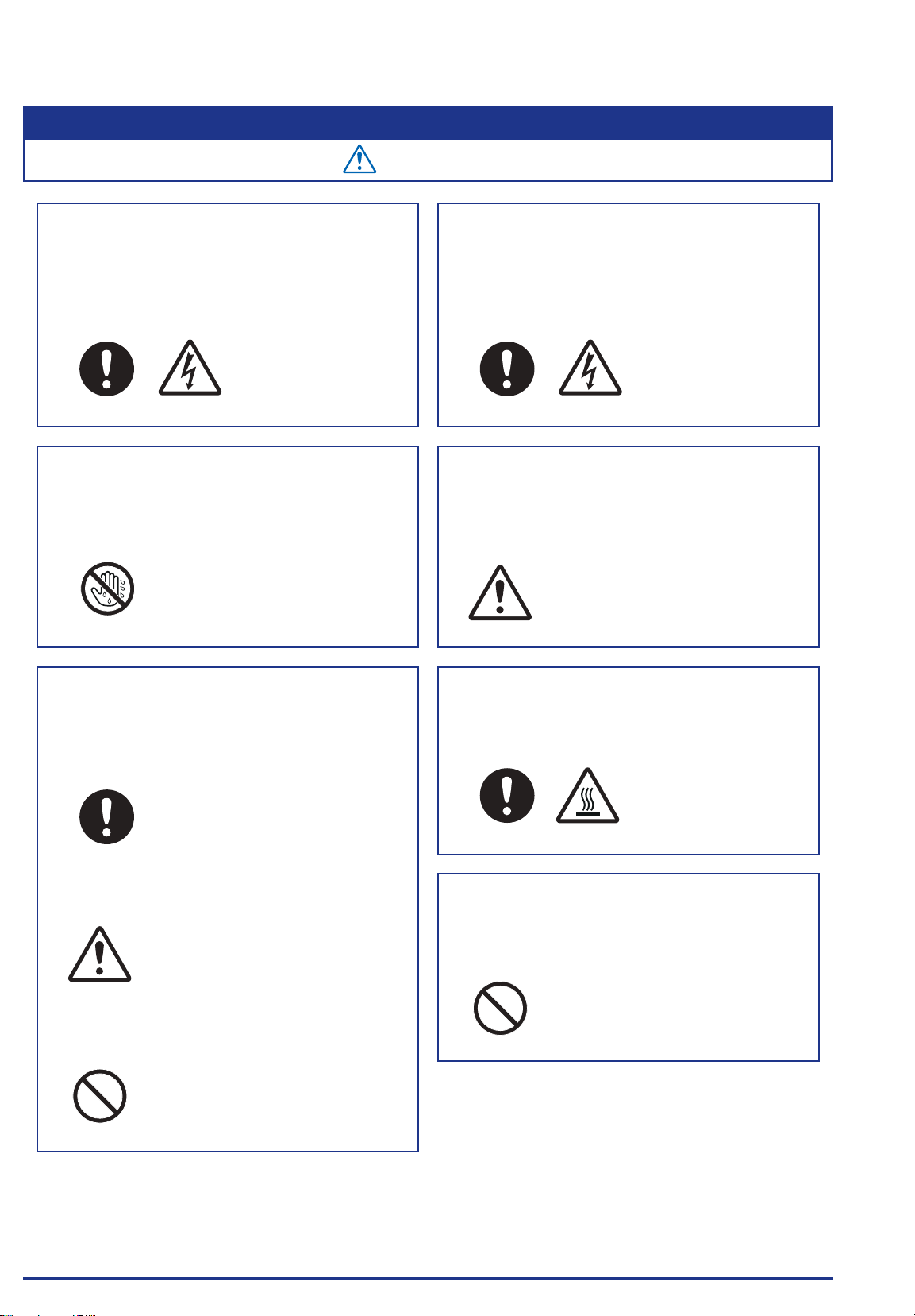
CAUTION
Do not touch the input terminals after the signal
cable is connected to the measuring objects that are
containing the voltage.
It will cause the electric shock.
•
Ensure that the GL840’s power source is positioned so that
•
it can easily be disconnected.
Watch out for
electrical shock
Do not touch the device with wet hands.
This can cause an electrical shock or malfunction.
•
Don't touch
with wet hands
Conrm the power of supplier of signal is turned
off before connecting the input cables to the input
terminal of this device to prevent the electric shock.
It will cause the electric shock.
•
Watch out for
electrical shock
Be careful of static electricity.
Static electricity may damage the device. To prevent this
•
from happening, touch a different metal object to discharge
any built-up static electricity before touching the GL840.
CAUTION
Do not input the voltage that is exceeding the
specication of this device.
If a voltage exceeding the specified value is input, the
•
semiconductor relay in the input section will be damaged.
Never input a voltage exceeding the specified value even
for a moment.
Have an enough margin from the specification of
•
withstanding voltage when using this device, it have to
consider a noise and change of the measurement voltage.
CAUTION
It will cause the fire or the electric shock when the voltage is
•
input to the defective device.
Do not block the air vent on the GL840.
This device will get damage when there is abnormal heat in
•
this device.
HIGH
TEMPERATURE
Conrm this device is not broken before the input
cable is connected to the input terminal.
It will cause the fire or the electric shock when the voltage is
•
input to the defective device.
Find Quality Products Online at: [email protected]
iv
www.GlobalTestSupply.com
Page 6
Safety Precautions
Safety Precautions
Strict observance
Strict observance
CAUTION
When using the wireless LAN (when option is
installed), please note the following:
If you have an implantable pacemaker or implantable
•
defibrillator installed, radio signals from the device may have
an effect on the operation of your implantable pacemaker or
implantable defibrillator.
When using the wireless LAN (when option is
installed), please note the following:
Turn off the device in places where wireless radio signal
•
use is restricted, such as on aircrafts and in hospitals. The
device can have an effect on electronic devices, medical
devices, etc., and may cause malfunctions.
Use prohibited
When using the wireless LAN (when option is
installed) in a medical establishment, please note the
following rules:
Please turn off the power of this product in hospital wards.
•
Each medical institution has its own usage prohibitions in
•
various areas. Be sure to follow these.
When using the wireless LAN (when option is
installed), please note the following:
In the event that the device has an effect on automatic
•
electronic devices such as cars or elevators, immediately
turn off the GL840.
Use prohibited
Do not use the device in any way not specied in this
manual. There is a danger that protective provisions
will have not been put in place.
Use prohibited
This GL840 is not meant for use with lifesaving devices or devices with mission-critical high reliability or
high safety requirements (medical devices, aerospace devices, shipping devices, nuclear power devices,
etc.). In the event that this GL840 causes injury or property damage when used under these circumstances,
the maker assumes absolutely no responsibility and is not liable.
The module connection terminal is for use only with
separately sold sensors and modules. Do not connect
any other devices. Doing so may damage the GL840.
Use prohibited
Find Quality Products Online at: [email protected]
www.GlobalTestSupply.com
v
Page 7

Introduction
Introduction
Thank you for purchasing the GL840 midi LOGGER.
Please read this manual thoroughly before attempting to use your new product to ensure that you use it correctly
and to its full potential.
Notes on Use
Be sure to read all of the following notes before attempting to use the GL840 midi LOGGER.
1. Note on the CE Marking
The GL840 midi LOGGER complies with the following standards.
• EN 61326-1 Class A standard based on the EMC directive (2014/30/EU)
• EN 61010-1:2010 3rd standard based on the LVD directive (2014/35/ EU)
• EN 301 489-17/-1, EN 300 328 standards based on the R&TTE directive (1999/5/EC)
Although the GL840 complies with the above-mentioned standards, be sure to use it correctly in accordance
with the instructions and notes provided in this manual.
Moreover, use of the GL840 by incorrect procedures may result in damage to the GL840 or may invalidate its
safeguards. Please conrm all of its notes regarding use and other related information to ensure correct use.
2. Warning
This is a Class A product according to the EMC directive. In a domestic environment, this product may cause
radio interference or may be affected by radio interference to the extent that proper measurement cannot be
performed.
3. Notes on Radio Law
When using the GL840 midi LOGGER in the wireless LAN (when option is installed), please note the
following:
Do not remove the technical standards compliance label. Do not use the device if it does not have a label
on it.
This GL840 uses the 2.4GHz frequency band.
The following devices and transmitters use the same frequencies and should not be used near this GL840:
• Microwave ovens
• Pacemakers and other industrial, science, and medical devices
• Radio transmitters used in mobile body identication devices on factory production lines, etc. (transmitters
requiring licensing)
• Specied low-power radio transmitters (transmitters not requiring licensing)
Communications may become slower or impossible due to radio interference.
The signal may be weak or communications may become slower or impossible depending on the
circumstances this GL840 is used in. Take particular note of steel-reinforced, metal, concrete, and other
structural materials that can inhibit radio waves.
Find Quality Products Online at: [email protected]
www.GlobalTestSupply.com
I
Page 8
Introduction
CCAB15LP4220T2
This GL840 is meant for use in Japan, the US, Europe,Taiwan,China and Korea. It has not been certied
for use under any other country’s radio laws.
The following are each region’s certication marks.
Japan
R 003WWA100913
US
Contains FCC ID: ANSBP3591
Europe
CE Mark
This device complies with part 15 of the FCC Rules. Operation is subject to the following two conditions:
(1)This device may not cause harmful interference, and (2)this device must accept any interference received,
including interference that may cause undesired operation.
FCC CAUTION
Change or modications not expressly approved by the party responsible for compliance could void the user’s
authority to operate the equipment.
Taiwan
Contains NCC ID:
China
CMIIT ID: 2015DJ5376
Korea
MSIP-CRI-KTM-B-568
This transmitter must not be co-located or operated in conjunction with any other antenna or transmitter.
4. Notes for Safe Operation
(1) Be sure to use the Graphtec-supplied AC adapter. In environments where there is a lot of noise or where
the power supply is unstable, we recommend that you ground the GL840.
(2) When a high-voltage signal cable has been connected to the main unit’s analog signal input terminal,
avoid touching the leads of the input terminal’s signal cable to prevent electrical shock due to high voltage.
(3) Ensure that the GL840’s power source is positioned so that it can easily be disconnected.
(4) When connecting the high voltage signal line to the analog signal input terminal using the 4ch voltage/
temperature terminal on the separately sold module (GS-4VT), avoid touching the leads of the input
terminal’s signal line to prevent electrical shock due to high voltage.
(5) Do not input the voltage that is exceeding the specication of this device.
• If a voltage exceeding the specied value is input, the semiconductor relay in the input section will be
damaged. Never input a voltage exceeding the specied value even for a moment. It will cause the re.
• Have an enough margin from the specication of withstanding voltage when using this device, it have to
consider a noise and change of the measurement voltage.
• Conrm this device is not broken before the input cable is connected to the input terminal.
• Please take care of the static electricity when the connecting the input cables or the thermocouples.
Find Quality Products Online at: [email protected]
www.GlobalTestSupply.com
II
Page 9

Introduction
• Do not touch the tip of thermocouples with bare hand after the thermocouples are connected to the
terminal of this device when the tip of thermocouples is not insulated.
The static electricity of a human body will cause damage to this device.
• Do not put the tip of thermocouples to the object which is containing the static electricity when the tip of
thermocouples is not insulated. The static electricity of object will cause damage to this device.
• Do not put the tip of thermocouples to the object which is containing the leaked high voltage of chassis or
metal etc. when the tip of thermocouples is not insulated.
The leaked high voltage of object will cause damage to this device.
• We recommend that the insulation tape puts on the tip of thermocouples before connecting the
thermocouples to the input terminals.
This will protect this device from the static electricity and the leaked high voltage.
* This applies to all the channels even if channel extension is used.
* The specication of all channels becomes the B-564, when the B-564 and the B-565 are installed.
5. Notes on Functions and Performance
(1) Be sure to connect the main unit to an AC or DC power supply that conforms to the rated range.
Connection to a non-rated power supply may cause the main unit to overheat and break down.
(2) Do not block the vent on the main unit.
Continued operation with the vent blocked may cause the main unit to overheat and break down.
(3) To avoid malfunctions and other damage, avoid using the GL840 in the following locations.
• Places exposed to high temperature and/or high humidity, such as in direct sunlight or near
heatingequipment.
(Allowable temperature range: 0 to 45°C (0 to 40°C when a battery pack is mounted, 15 to 35°C when
battery is being charged), Allowable humidity range: 5 to 85%R.H., non-condensing)
• Locations subject to excessive salt spray or heavy fumes from corrosive gas or solvents.
• Excessively dusty locations.
• Locations subject to strong vibrations or shock.
• Locations subject to surge voltages and/or electromagnetic interference.
(4) If the main unit becomes soiled, wipe it off using a soft, dry cloth. Use of organic solvents (such as thinner
or benzene) causes deterioration and discoloration of the outer casing.
(5) Do not use the GL840 in the vicinity of other devices which are susceptible to electromagnetic
interference.
(6) Measured results may not conform to the stated specications if the GL840 is used in an environment
which is subject to strong electromagnetic interference.
(7) Insofar as possible, position the GL840 input signal cables away from any other cables which are likely to
be affected by electromagnetic interference.
(8) For stabilized measurement, allow the GL840 to warm up for at least 30 minutes after turning it on.
Find Quality Products Online at: [email protected]
www.GlobalTestSupply.com
III
Page 10
Introduction
(9) When you want to use in combination of the Petit LOGGER GL100-WL (separately sold) and various
modules (such as GS sensor and terminal / adapter), please refer to the GL100 User’s Manual.
When using in combination described above, please be careful to the operating environment because
•
the environmental conditions of the GL840 midi LOGGER are applied.
It may cause abnormal operation or damage.
• Allowable temperature range: 0 to 45°C, Allowable humidity range: 5 to 85%R.H, non-condensing.
(0 to 40°C when battery-powered / 15 to 35°C when charging)
When using temperature and humidity sensor (GS-TH) and the GL840 at the same time, the
operating environment of GL840 is applied.
Temperature and Humidity Sensor (GS-TH):
•
• Humidity sensors measure the change in dielectric capacity of water adsorption. As a result, humidity
from organic materials such as ne particles or exhaust gas may have an effect on the sensor. Use
in environments with large quantities of these organic materials may lead to signicant measurement
inaccuracies.
CO2 Sensor (GS-CO2 ):
•
• Because exhaled CO2 may have an effect on the sensor readings, do not use the sensor to take
measurements near the face.Additionally, should air ow to the sensor be blocked, it will result in
inaccurate readings, so be sure to keep vent holes open.
Illumination / Ultraviolet Sensor (GS-LXUV):
•
• When measuring illumination or ultraviolet light that can have harmful effects on the eyes or skin, be
sure to use protective eyewear, shielding, etc.
• If the sensor becomes dirty, it may affect measurements, so wipe it with a soft cloth when it becomes
dirty.
• Take care to avoid cracking the sensor when handling it. If the sensor is damaged or cracked it may
affect measurements, so replace the sensor.
Others
•
• Depending on the usage and operating environment of Temperature and Humidity Sensor (GSTH), CO2 Sensor (GS-CO2), and Illumination / Ultraviolet sensor (GS-LXUV), it is recommended to
replace periodically the sensor with new one because the sensor performance may be deteriorated.
• When connecting the GS-3AT (3-axis accelerometer) module to the GL840 midi LOGGER, please
note that IP54 standard is not satised.
Find Quality Products Online at: [email protected]
IV
www.GlobalTestSupply.com
Page 11

Introduction
Notes on the Use of This Manual
(1) All rights reserved. No part of this publication may be reproduced, stored in a retrieval system, or transmitted, in
any form or by any means, without the prior written permission of Graphtec Corporation.
(2) The specications and other information in this manual are subject to change without notice.
(3) While every effort has been made to supply complete and accurate information about this product, please
address any inquiries about unclear information, possible errors, or other comments to your sales representative
or nearest Graphtec vendor.
(4) Notwithstanding the preceding paragraph, Graphtec Corporation assumes no liability for damages resulting
from the use of the information contained herein or of the product.
About Registered Trademarks
Microsoft and Windows are registered trademarks or trademarks of Microsoft Corporation in the U.S. and
elsewhere.
Other company names and product names included in this manual are registered trademarks or trademarks of
their respective companies.
Copyright
All copyrights regarding this manual belong to Graphtec Corporation.
Find Quality Products Online at: [email protected]
www.GlobalTestSupply.com
V
Page 12

CONTENTS
CONTENTS
To Ensure Safe and Correct Use ................................................i
Safety Precautions ...........................................................ii
Introduction .................................................................I
Notes on Use ................................................................. I
Notes on the Use of This Manual ................................................V
About Registered Trademarks ...................................................V
Copyright ...................................................................V
CHAPTER 1 General Description
1.1 Overview ............................................................. 1-2
1.2 Features .............................................................1-2
1.3 Operating Environment ................................................. 1-3
Ambient Operating Conditions ................................................. 1-3
Warming-up Before Use .....................................................1-3
Conguration When in Use ................................................... 1-4
1.4 Notes on Temperature Measurement .....................................1-5
1.5 Notes on Using the Monitor .............................................1-5
1.6 Changing the Display Language .........................................1-5
CHAPTER 2 Checks and Preparation
2.1 Checking the Outer Casing .............................................. 2-2
2.2 Checking the Accessories ..............................................2-2
2.3 Nomenclature and Functions ............................................2-3
2.4 Connecting the Power Cable and Turning on the Power ..................... 2-4
2.5 Connecting the Signal Input Cables ..................................... 2-6
2.6 Logic Alarm Cable Connection and Functions .............................. 2-8
2.7 Mounting the SD Memory Card .........................................2-11
2.8 Installing the Wireless LAN Unit (B-568: Option) ........................... 2-13
2.9 Connecting to a PC ...................................................2-15
2.10 Using the Battery Pack (B-569 : Option) ..................................2-18
2.11 Connecting the Humidity Sensor (Optional) ............................... 2-20
2.12 Mounting and Removing the Standard Terminal and
Withstand high-voltage high-precision Terminal ...........................2-21
2.13 Mounting the Extension Terminal Base (Optional) and
Extension Terminal Cable (Optional) .....................................2-23
2.13.1 Mounting the extension terminal base ...................................... 2-23
2.13.2 Mounting multiple extension terminals .....................................2-25
2.14 Precautions to Observe When Performing Measurement .................... 2-29
2.15 Noise Countermeasures ...............................................2-32
2.16 Connecting the Temperature and Humidity Sensor (GS-TH) (Optional) ........2-33
Find Quality Products Online at: [email protected]
www.GlobalTestSupply.com
C-1
Page 13

CONTENTS
2.17
Connecting the 3-axis Acceleration / Temperature Sensor (GS-3AT) (Optional)
2.18 Connecting the 4ch Voltage / Temperature Terminal (GS-4VT) (Optional) ......2-35
2.19 Connecting the 4ch Thermistor Terminal (GS-4TSR) (Optional) .............. 2-38
2.20 Connecting the Illumination / Ultraviolet Sensor (GS-LXUV) (Optional) ........2-41
2.21 Connecting the CO2 Sensor (GS-CO2) (Optional) ......................... 2-42
2.22 Connecting the Adapter for AC Current Sensor (GS-DPA-AC) (Optional) ...... 2-43
2.23 Connecting the Branch Adapter for GS (GS-DPA) (Optional) ................ 2-45
2.24 When Fixing the GL840 Body .......................................... 2-48
2.25 Setting the Date and Time. . . . . . . . . . . . . . . . . . . . . . . . . . . . . . . . . . . . . . . . . . . . . 2-49
CHAPTER 3 Settings and Measurement
3.1 Window names and functions ...........................................3-2
3.2 Key Operation ....................................................... 3-8
3.3 Operation Modes .....................................................3-17
3.4 Setting Menus .......................................................3-21
(1) AMP settings ............................................................3-21
(2) DATA settings ...........................................................3-45
(3) TRIG settings ...........................................................3-50
(4) Interface settings ........................................................3-56
(5) WLAN setting ...........................................................3-61
(6) OTHER settings .........................................................3-69
(7) FILE menu .............................................................3-73
(8) File box ................................................................3-77
(9) Text input ..............................................................3-79
(10) Data replay menu .......................................................3-80
(11) Integrated bar graph display ...............................................3-84
(12) NAVI menu ............................................................3-88
(13) Quick setting ...........................................................3-90
(14) To cancel key lock by password ............................................3-91
3.5 WEB Server Function ................................................ 3-92
..2-34
3.6 List of Error Codes .................................................. 3-96
CHAPTER 4 Specication
4.1 Standard Specications ................................................4-2
Standard Specications ...................................................... 4-2
Memory devices ............................................................4-3
PC I/F ....................................................................4-3
Monitor ...................................................................4-3
Standard terminal input section (GL840-M and B-564) ..............................4-4
Withstand high-Voltage high-precision terminal input section (GL840-WV: B-565) ........4-6
4.2 Function Specications ...............................................4-8
Function Specications ......................................................4-8
Trigger/Alarm Functions ......................................................4-8
External Input/Output Functions ...............................................4-9
Find Quality Products Online at: [email protected]
C-2
www.GlobalTestSupply.com
Page 14

CONTENTS
4.3 Accessories/Optional Accessories . . . . . . . . . . . . . . . . . . . . . . . . . . . . . . . . . . . . . .4-10
Control Software ..........................................................4-10
Accessories .............................................................. 4-10
Wireless Unit B-568 (Option) .................................................4-10
Battery Pack B-569 (Option) ..................................................4-11
Humidity Sensor B-530 (Option) ...............................................4-11
List of Options ............................................................ 4-12
4.4 External Dimensions ..................................................4-13
INDEX ..............................................I-1
Find Quality Products Online at: [email protected]
www.GlobalTestSupply.com
C-3
Page 15

CHAPTER 1 General Description
CHAPTER 1 General Description
This chapter provides a general description of the GL840 and its features.
PRODUCT SUMMARY
1.1 Overview
1.2 Features
1.3 Operating Environment
1.4 Notes on Temperature Measurement
1.5 Notes on Using the Monitor
1.6 Changing the Display Language
Find Quality Products Online at: [email protected]
www.GlobalTestSupply.com
1-1
Page 16

CHAPTER 1 General Description
1.1 Overview
The GL840 is a compact, lightweight, multi-CH, and multi-purpose data logger with a 7-inch color display.
20CH measurements are available with the standard terminal or Withstand high-voltage high-precision
terminal, and 200CH measurements are available with the extension terminal base. In addition, when
connecting various modules, the voltage, temperature and humidity as well as the acceleration, AC current,
CO2, and illuminance / ultraviolet etc. can be measured.
The GL840 can save the high-capacity measurement data directly in the internal memory or SD memory
card.
For the PC interface, as USB and Ethernet is included as standard, system conguration according to use
is possible. As the Ethernet function is equipped with both WEB server and FTP server functions, remote
supervision and data transfer are also possible. In addition, when the wireless LAN and Petit LOGGER
GL100-WL are combined by installing the wireless unit, the multipurpose remote measurement is also
possible.
1.2 Features
Input
Adoption of a pluggable M3 screw type input terminal facilitates wiring.
•
20CH measurements are supported by the standard terminal or Withstand high-voltage high-precision
•
terminal, and 200CH measurements are supported by the extension terminal base.
When using the Graphtec’s GS series and terminal / adapter, the acceleration, AC current, CO2, and
•
illuminance / ultraviolet measurements are also possible.
Because that standard terminal and Withstand high-voltage high-precision terminal have a whole CH
•
isolated, the different standard signals can be measured at the same time. In addition, when using the
Withstand high-voltage high-precision terminal, the measure environmental conditions of high withstand
voltage can be applied.
Display & Operation
With the GL840’s high-resolution 7-inch TFT color liquid crystal display, you can conrm the waveforms of
•
measured data and each channel’s settings at a glance.
Easy operation is achieved through a straightforward menu structure and key allocation which resembles
•
mobile phones.
Data Capture
The high-capacity measurement data can be saved directly in the internal memory or SD memory card.
•
Because the SD memory card is used as an external memory, you can measure a long period of time with
•
peace of mind while data backup.
* When the optional wireless LAN unit is installed, the SD memory card cannot be inserted into the SD
CARD2 slot.
Because disk image can be used for the internal memory, multiple data can be saved.
•
The new ring memory capture function maintains latest data even after capturing for a long term. (You
•
need to set how long you want to keep data.)
For voltage, temperature and humidity measurements, data can be captured at sampling rates of up to
•
10 msec per channel by using fewer measuring channels. (Temperature measurement can be done at
sampling rates of 100 msec and higher.)
The GL840 is equipped with the relay recording function, and 2GByte or more data can be saved by
•
switching the to the other le without data missing. (When the capacity of one le reaches 2GByte, the le
is switched.)
Find Quality Products Online at: [email protected]
www.GlobalTestSupply.com
1-2
Page 17
CHAPTER 1 General Description
Data Control & Processing
The application software provided lets you set conditions and monitor data on a PC.
•
The USB drive mode function enables the internal memory and SD memory card to be recognized as an
•
external drive by the PC.
(Connect the GL840 to the PC and turn on the GL840 power while holding down the [START] key.)
The WEB server function enables control and monitoring from a remote location without using dedicated
•
software
The FTP client function enables backup of measurement data to the FTP server.
•
The NTP client function enables synchronization of the time with the NTP server.
•
When optional wireless LAN unit is installed, the data capture can be performed remotely by controlling
•
the GL100-WL.
1.3 Operating Environment
This section explains the operating environment for the GL840.
Ambient Operating Conditions
(1) Ambient temperature and humidity (the GL840 must be operated within the following ranges.)
• Temperature range: 0 to 45°C (0 to 40°C when a battery pack is mounted, 15 to 35°C when battery is
being charged)
• Humidity range: 5 to 85%R.H.
(2) Environment (do not use in the following locations.)
• A Location such as being exposed to direct sunlight
• Locations exposed to salty air, corrosive gases, or organic solvents
• Dusty locations
• Locations subject to vibration or impact
• Locations subject to voltage surge or electromagnetic interference such as lightning or electric furnaces
(3) Installation category (over-voltage category)
• The GL840 belongs to Installation Category II dened in IEC60664-1.
• Never use the GL840 for Installation Category III or IV.
(4) Measurement category
• The standard terminals on the GL840 are not used for Measurement Category II, III, and IV.
• The Withstand high-voltage high-precision terminal for the GL840 belongs to Category II. However, it is
not available for Category III or IV.
•If condensation occurs...
Condensation occurs in the form of water droplets on the device surfaces and interior when the GL840
is moved from a cold to a warm location. Using the GL840 with condensation will cause malfunctioning.
Wait until the condensation has disappeared before turning on the power.
Warming-up Before Use
The GL840 should be allowed to warm up with the power turned on for approximately 30 minutes to ensure
that it operates according to the specied performance.
Find Quality Products Online at: [email protected]
www.GlobalTestSupply.com
1-3
Page 18
CHAPTER 1 General Description
Conguration When in Use
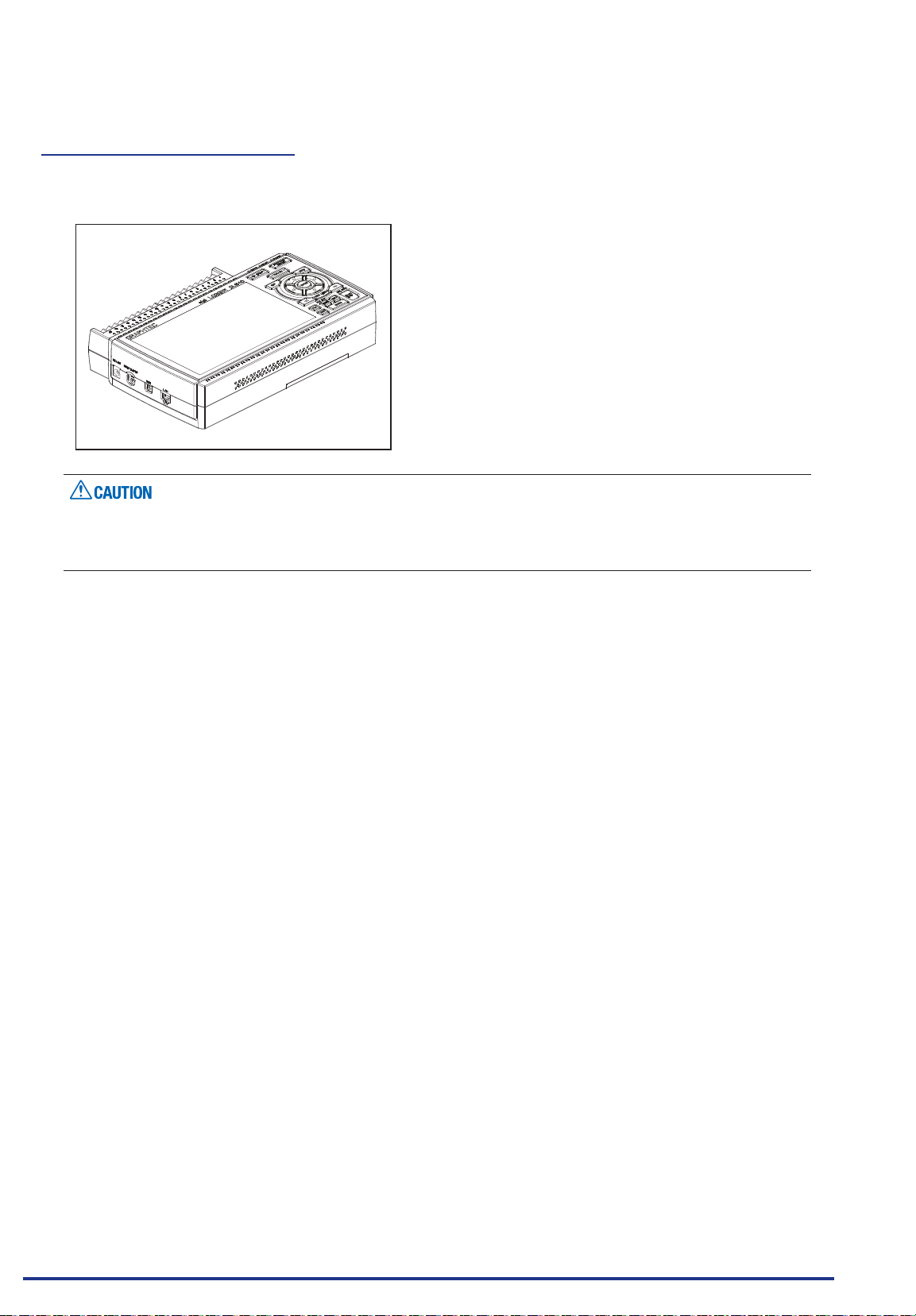
Do not use the GL840 standing upright or at an angle. It must always be laid at or inclined on the stands.
<Usage Conguration>
Do not block the air vent on the GL840, as this will cause malfunctioning.
Measurement accuracy may not be satisfactory if the system is used in a condition other than described
above.
Find Quality Products Online at: [email protected]
www.GlobalTestSupply.com
1-4
Page 19
CHAPTER 1 General Description
1.4 Notes on Temperature Measurement
Please observe the following precautions when performing temperature measurement.
Do not block the air vents. Always provide a space of at least 30 cm on all sides of the GL840.
•
For stabilized temperature measurement, allow the GL840 to warm up for at least 30 minutes after turning
•
it on.
Exposure of the input terminals to direct drafts, direct sunlight, or abrupt changes in temperature may
•
impair the equilibrium of the input parts and result in measurement errors. To measure temperature in
such an environment, take appropriate countermeasures such as changing the installation site of the
GL840.
To conduct measurement in noisy environments, connect the GL840’s GND terminal to ground (Refer to
•
“2.15 Noise Countermeasures”.).
If measured values uctuate due to noise, set to a slower sampling speed (Refer to “(2) DATA setting” in “3.4
•
Setting Menus”.).
1.5 Notes on Using the Monitor
The monitor is an LCD display unit, and so the display will vary depending on the operating environment.
If the screen saver function is used, it will operate and clear the screen if no operations are performed
during the preset time. If the screen saver operates, press any key to restore the display.
Condensation may form on the LCD screen if the GL840 is moved from a cold to a warm location. If this
•
occurs, wait until the LCD screen warms up to room temperature.
The LCD screen is manufactured to extremely high precision. Black dots may appear, or red, blue, and
•
green dots may not disappear. Likewise, streaks may appear when viewed from certain angles. These
phenomena are due to the LCD screen construction, and are not signs of a fault.
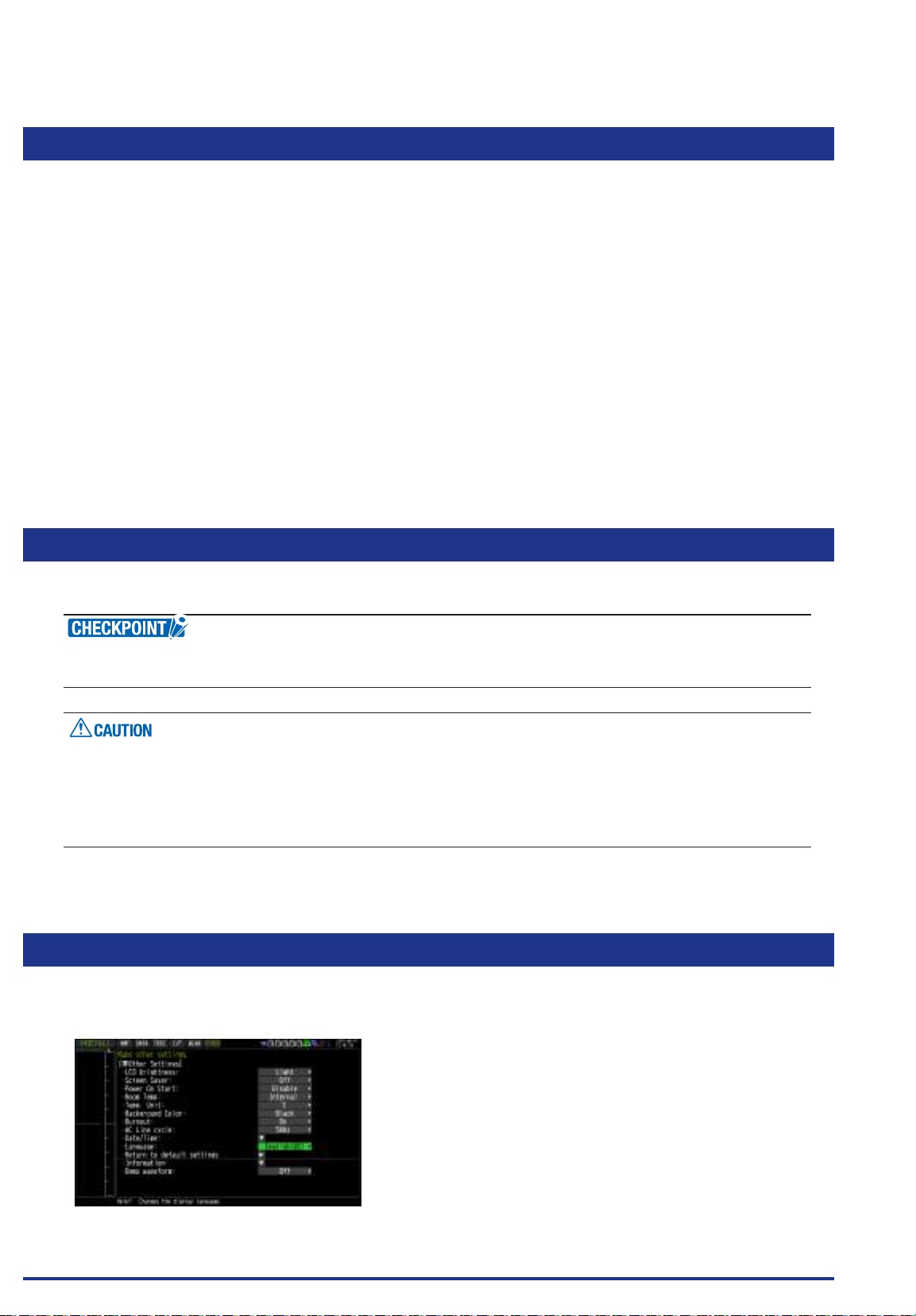
1.6 Changing the Display Language
You can choose the language displayed on the screen. The default display language is set to English when
the GL840 is shipped overseas. To change the display language, see the instructions in "OT HER:Language".
Find Quality Products Online at: [email protected]
www.GlobalTestSupply.com
1-5
Page 20

CHAPTER 2 Checks and Preparation
CHAPTER 2 Checks and Preparation
This chapter explains how to check the main module's external casing and accessories, and how to prepare the
main module for operation.
PRODUCT SUMMARY
2.1 Checking the Outer Casing
2.2 Checking the Accessories
2.3 Nomenclature and Functions
2.4
2.5 Connecting the Signal Input Cables
2.6 Logic Alarm Cable Connection and Functions
2.7 Mounting the SD Memory Card
2.8 Installing the Wireless LAN Unit (B-568: Option)
2.9 Connecting to a PC
2.10 Using the Battery Pack (B-569 : Option)
2.11 Connecting the Humidity Sensor (Optional)
2.12
2.13
2.14
2.15 Noise Countermeasures
2.16
2.17
2.18
2.19
2.20
2.21 Connecting the CO2 Sensor (GS-CO2) (Optional)
2.22
2.23
2.24 When Fixing the GL840 Body
Find Quality Products Online at: [email protected]
www.GlobalTestSupply.com
2.25 Setting the Date and Time
Connecting the Power Cable and Turning on the Power
Mounting and Removing the Standard Terminal and Withstand
high-voltage high-precision Terminal
Mounting the Extension Terminal Base (Optional) and
Extension Terminal Cable (Optional)
Precautions to Observe When Performing Measurement
Connecting the Temperature and Humidity Sensor (GS-TH) (Optional)
Connecting the 3-axis Acceleration / Temperature Sensor (GS3AT) (Optional)
Connecting the 4ch Voltage / Temperature Terminal
(GS-4VT) (Optional)
Connecting the 4ch Thermistor Terminal (GS-4TSR) (Optional)
Connecting the Illumination / Ultraviolet Sensor (GS-LXUV)
(Optional)
Connecting the Adapter for AC Current Sensor (GS-DPAAC) (Optional)
Connecting the Branch Adapter for GS (GS-DPA) (Optional)
2-1
Page 21
CHAPTER 2 Checks and Preparation
2.1 Checking the Outer Casing
After unpacking, check the GL840's outer casing before use. In particular, please check for the following:
Surface scratches
•
Other aws such as stains or dirt
•
2.2 Checking the Accessories
After unpacking, check that the following standard accessories are included.
Standard Accessories
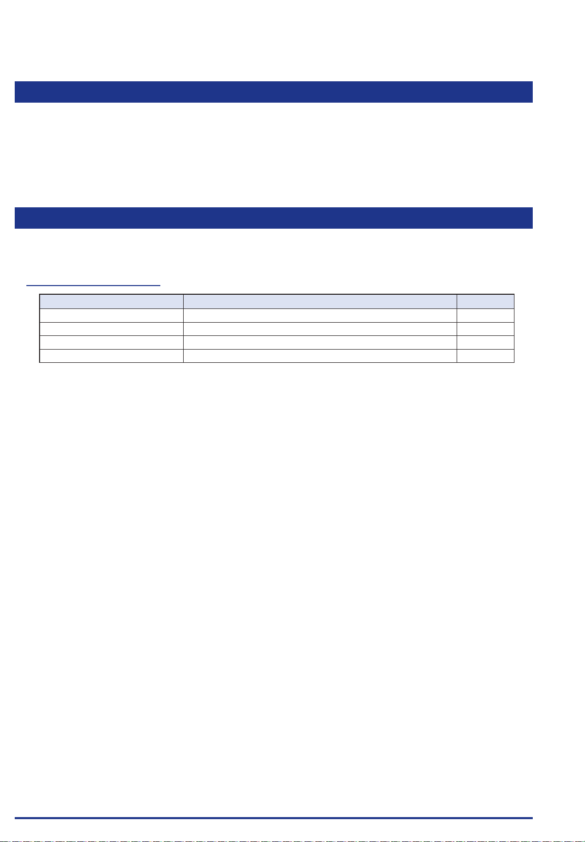
Item Remarks Quantity
Quick Start Guide GL840-UM-85x 1
CD-ROM User's Manual, Application software 1
AC cable/AC adapter 100 to 240 VAC, 50/60 Hz 1
Ferrite core Used to attach to the USB cable. 1
Find Quality Products Online at: [email protected]
2-2
www.GlobalTestSupply.com
Page 22
CHAPTER 2 Checks and Preparation
2.3 Nomenclature and Functions
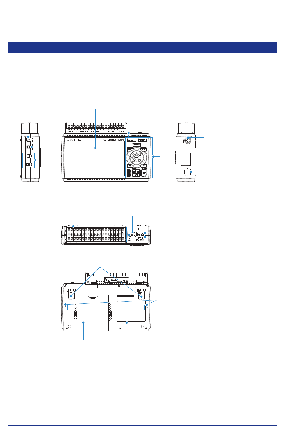
This section describes the names and function of parts of the GL840.
External input/output terminals
• LOGIC/PULSE
• EXT TRIG/SAMPLE
• ALARM
Input/output cable for GL (Cable is the option B-513)
PC interface terminals
• USB
• LAN
Analog signal input terminals
• Standard terminal (B-564)
• Withstand high-Voltage
high-precision terminal (B-565)
Monitor
Operation status LEDAC adapter jack
• POWER ON when the power is ON
Blinking while accessing to the
memory
• START ON during data capture
• CHARGE ON while the battery is charging
Control panel keys
GND terminal
Power jack for humidity sensor
Humidity sensor (Option: when using the B-530)
Wireless LAN connection terminal
Wireless unit (Option: when using the B-568)
SD CARD2
GS sensor and terminal/
adapter connection terminal
(Option: when using
• Temperature and humidity sensor
• 4ch voltage/temperature terminal
• 3-axis acceleration/temperature sensor
• 4ch thermistor terminal
• Adapter for AC current sensor
• CO2 sensor
• Illumination/ultraviolet sensor
• Branch adapter for GS.)
Power switch
Tilt foot
Module xing screw
LabelBattery cover
Two battery pack can be installed
(Battery pack is the option B-569)
Find Quality Products Online at: [email protected]
www.GlobalTestSupply.com
2-3
Page 23
CHAPTER 2 Checks and Preparation
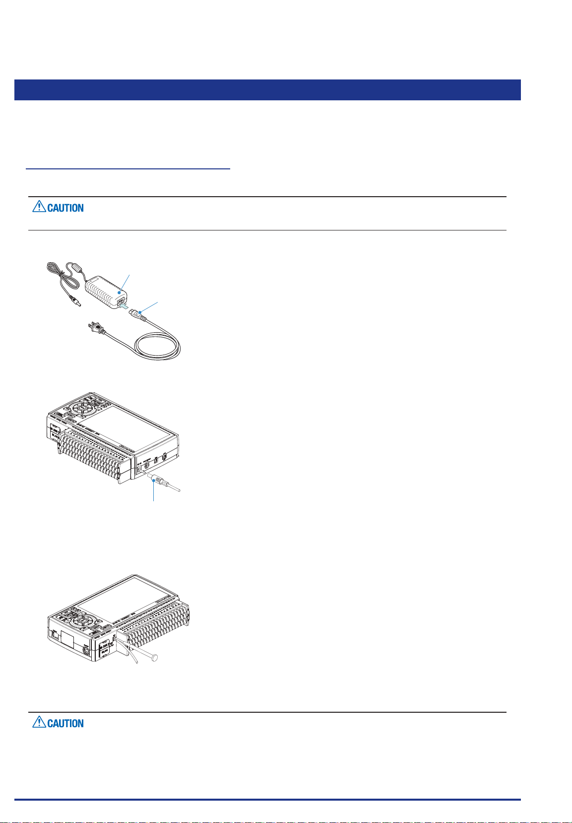
2.4 Connecting the Power Cable and Turning on the Power
This section describes how to connect the power cable and turn on the power. The connection method will
vary depending on the type of power supply used.
Connecting to an AC Power Supply
Use the AC cable and AC adapter that are provided as accessories.
Be sure to use the AC adapter that is supplied as a standard accessory.
(1) Plug the AC cable into the AC adapter.
AC adapter
AC cable
(2) Connect the output side of the AC adapter to the connector on the GL840.
AC adapter cable
(3) Using the at-blade screwdriver, press against the minus (-) button above the GND terminal, while
connecting the grounding cable to the GL840.
Connect the other end of the cable to ground.
(4) Plug the AC cable into the mains power outlet.
(5) Press the power switch on the GL840 to the ON side to turn on the power.
Always connect the GND terminal and refer to the safety precautions.
The GL840 must be grounded even when connected to other devices and sharing a common ground level.
Find Quality Products Online at: [email protected]
www.GlobalTestSupply.com
2-4
Page 24
CHAPTER 2 Checks and Preparation
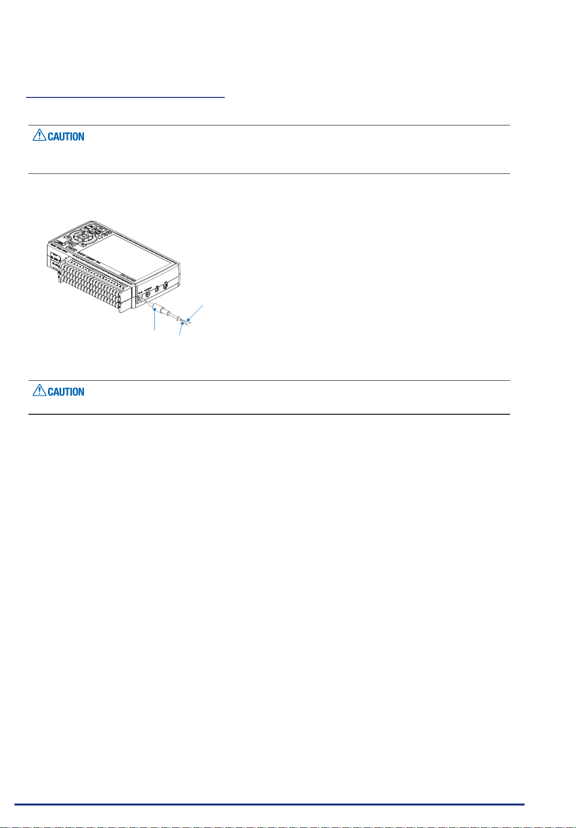
Connecting to a DC Power Supply
Use the optional DC drive cable (B-514).
Use a power supply within the 8.5 to 26.4 VDC range.
•
For DC drive cable, please be sure to use the B-514.
•
(1) Congure the tip of the DC drive cable (B-514: 2m) to enable it to be connected to the DC power supply.
(2) Connect the DC output side to the power supply connector on the GL840.
Shielded lead (- side)
DC drive cable
(B-514: Option)
(3) Connect the DC input side to the DC power supply.
Be sure to check the polarity of the wire tips when performing wiring.
(4) Press the power switch on the GL840 to the ON side to turn on the power.
White (+ side)
Find Quality Products Online at: [email protected]
www.GlobalTestSupply.com
2-5
Page 25
CHAPTER 2 Checks and Preparation
+
+
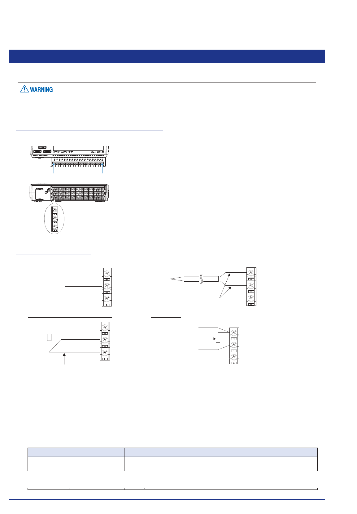
2.5 Connecting the Signal Input Cables
This section describes how to connect the signal input cables.
During wiring, conrm that the signal's supply source is turned OFF to prevent electrical shocks.
Also, position the GL840 input cable away from any power lines and ground cables.
Terminal Conguration and Signal Types
Terminal assignment of standard terminal and Withstand high-voltage high-precision terminal is common.
CH1 CH20
+
b
Connection diagram
DC voltage input Thermocouple input
Voltage input
-
Resistance temperature detector input Current input
A
B
b
Lead wire resistance should be 10Ω or
less per wire, three wires need to be
same length.
+
-
b
DC current
-
Compensationcopper wire
+
-
Shunt resister
Ex: The current is converted to the voltage in the shunt register.
For 4 to 20mA current input, installing 250 ohms (0.1%)
resister for converting 1 to 5V.
* 250 ohms shunt register is the option B551.
+ .....................................High-voltage terminal (terminal for high-voltage input signals)
- ......................................Low-voltage terminal (terminal for low-voltage input signals)
b .....................................Dedicated terminal when connecting resistance temperature detector
* Resistance temperature detector input terminals A (+) and B (-) are isolated within each channel.
Terminal b is shorted within all channels.
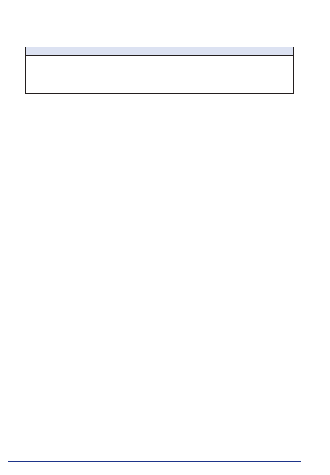
Item Description
Input conguration Isolated input, scanning
Measurement range 20, 50, 100, 200, 500 mV/F.S.; 1, 2, 5, 10, 20, 50, 100 V/F.S.; 1-5V
Find Quality Products Online at: [email protected]
Thermocouples K, J, E, T, R, S, B, N, W (WRe 5-26)
Resistance temperature detector Pt100, JPt100, Pt1000 (IEC751)
www.GlobalTestSupply.com
2-6
Page 26
CHAPTER 2 Checks and Preparation
Item Description
A/D resolution 16-bit (Effective resolution: Approx. 1/40,000 of the +/- range)
Filter Off, 2, 5, 10, 20, 40
Filter operation is on a moving average basis.
The average value of the set sampling count is used.
If the sample interval exceeds 30 seconds, the average value of data
obtained in a sub-sample (30 seconds) is used.
Find Quality Products Online at: [email protected]
www.GlobalTestSupply.com
2-7
Page 27
CHAPTER 2 Checks and Preparation
2.6 Logic Alarm Cable Connection and Functions
This section describes how to connect the logic alarm cables and the functions of cable.
During wiring, conrm that the signal's supply source is turned OFF to prevent electrical shocks.
Also, position the GL840 input cable away from any power lines and ground cables.
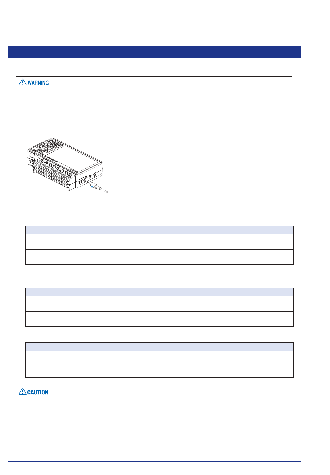
The Input/output cable for GL (B-513: Option) enables logic/pulse input, external trigger input, and alarm
signal output.
Connect the Input/out put cable for GL (B-513: Option) to the external input/output terminal as shown below.
Input/output cable for GL
(B-513: Option)
Logic/Pulse Input Specications
Item Description
Number of input channels 4
Input voltage range 0 to +24V max. (single-ended ground input)
Threshold level Approx. +2.5V
Hysteresis Approx. 0.5 V (+2.5 to +3 V)
* Switch between logic and pulse input.
Trigger Input/External Sampling Input Specications
Item Description
Number of input channels 1
Input voltage range 0 to +24V max. (single-ended ground input)
Threshold level Approx. +2.5V
Hysteresis Approx. 0.5 V (+2.5 to +3 V)
Alarm Output Specications
Item Description
Number of Output channels 4
Output format Open collector output
+5 V, 10 KΩ pull-up resistance
* See the next page for details on alarm output
When the power is turned OFF or ON, the GL840 temporarily becomes the alarm state.
Find Quality Products Online at: [email protected]
www.GlobalTestSupply.com
2-8
Page 28
CHAPTER 2 Checks and Preparation
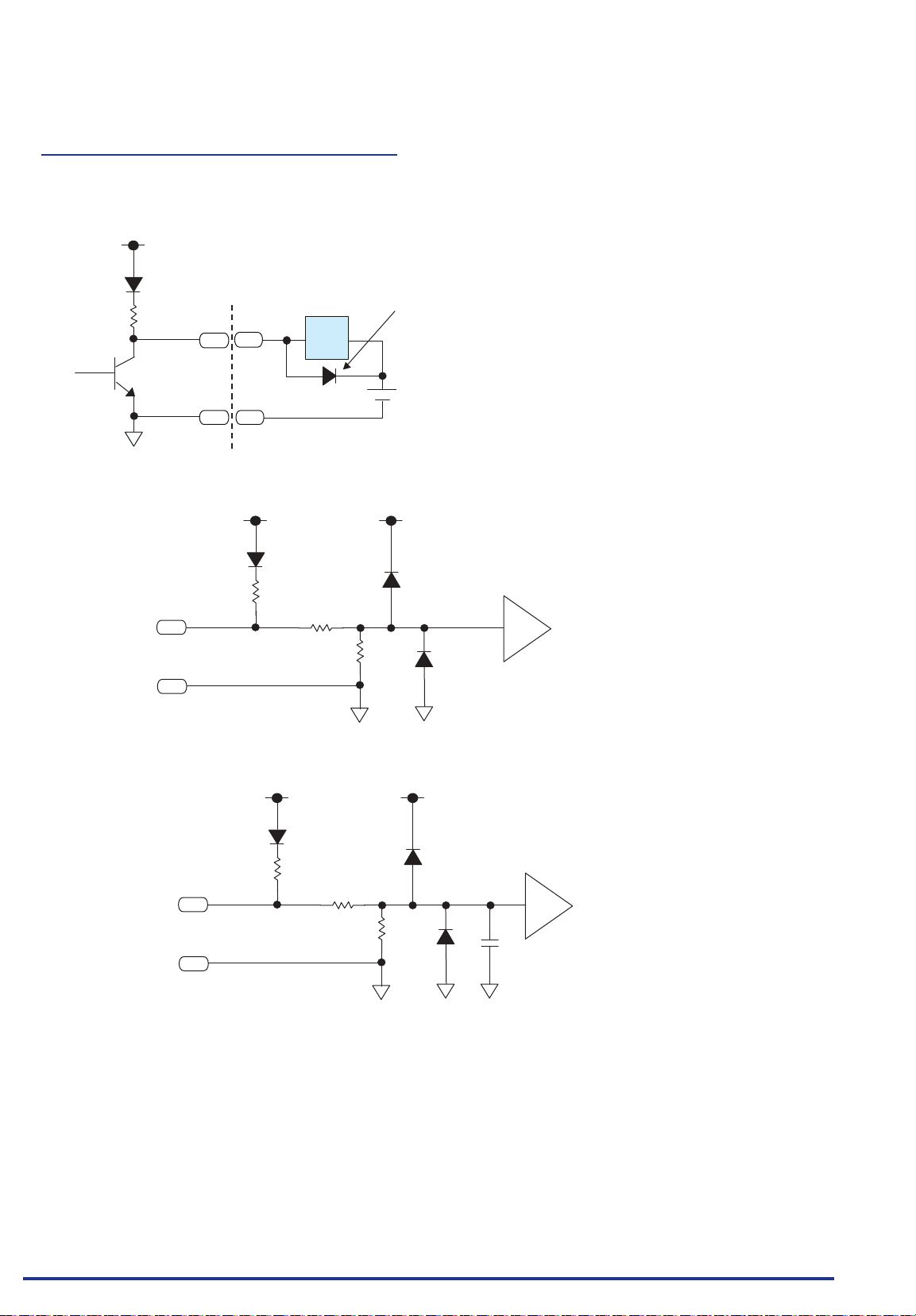
Internal equivalent circuit of I/O circuit
Alarm output
•
+5V
Maximum ratings of the transistor for alarm output
VCEO (Collector-emitter voltage) : 30 V
IC (Collector current) : 0.5A
PC (Collector dissipation) : 0.2W
* The maximum ratings must not be exceeded.
10K Ω
2SC2411K
Logic/pulse input
•
LOGIC/PULSE
GND
Example of external connection
ALARM
Load
GND
+5V +5V
10K Ω
68K Ω
220KΩ
Required for an inductive
load such as a relay
DC
(5 to 24V)
Comparator
Trigger input/external sampling input
•
+5V
10K Ω
TRIGGER/SAMPLE
GND
68K Ω
+5V
Comparator
220KΩ
0.01μF
Find Quality Products Online at: [email protected]
www.GlobalTestSupply.com
2-9
Page 29
CHAPTER 2 Checks and Preparation
Wiring
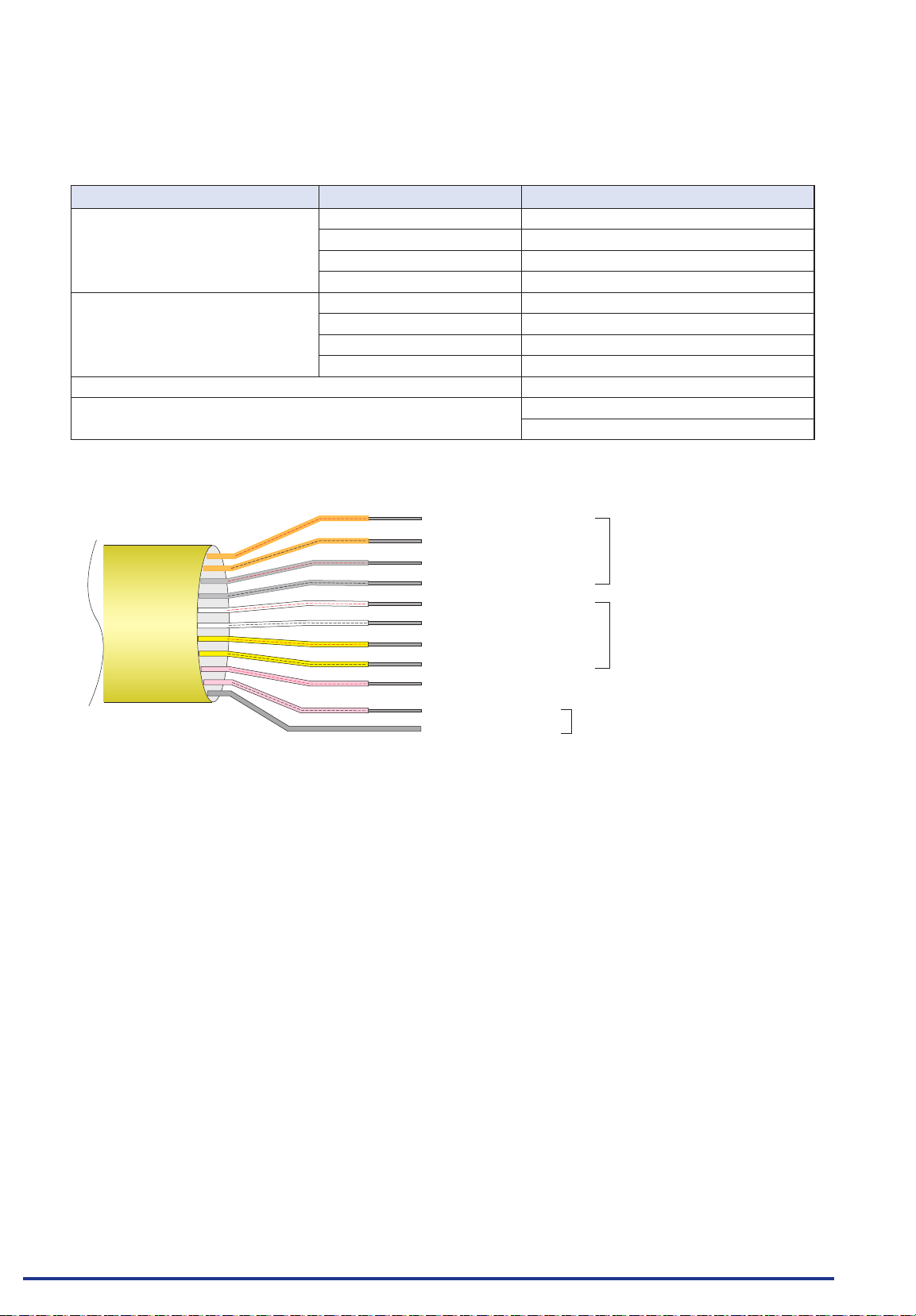
Cable tips are bare tips. Perform wiring for the necessary functions.
Signal Name Channel Number Wire Color
Logic/Pulse Input 1 Orange with red dotted line
2 Orange with black dotted line
3 Grey with red dotted line
4 Grey with black dotted line
Alarm output 1 White with red dotted line
2 White with black dotted line
3 Yellow with red dotted line
4 Yellow with black dotted
Trigger input/External sampling input Pink with red dotted line
GND Pink with black dotted line
* Switch between logic and pulse.
Shielded
Orange with red dotted line : 1
Orange with black dotted line : 2
Grey with red dotted line : 3
Grey with black dotted line : 4
White with red dotted line : 1
White with black dotted line : 2
Yellow with red dotted line : 3
Yellow with black dotted line : 4
Pink with red dotted line : Trigger input/External sampling input
Pink with black dotted line
Shielded
Logic/Pulse input
Alarm output
GND
Find Quality Products Online at: [email protected]
www.GlobalTestSupply.com
2-10
Page 30
CHAPTER 2 Checks and Preparation
2.7 Mounting the SD Memory Card
When the SD memory card is inserted, make sure that the card is not locked. If locked, the data cannot be
•
captured.
Please do not remove the SD memory card while accessing to the SD memory card (Device Access display
•
is displayed in "red" and POWER LED is blinking.). The captured data may be damaged.
When inserting the large capacity SD memory card, it may take some time to recognize it.
•
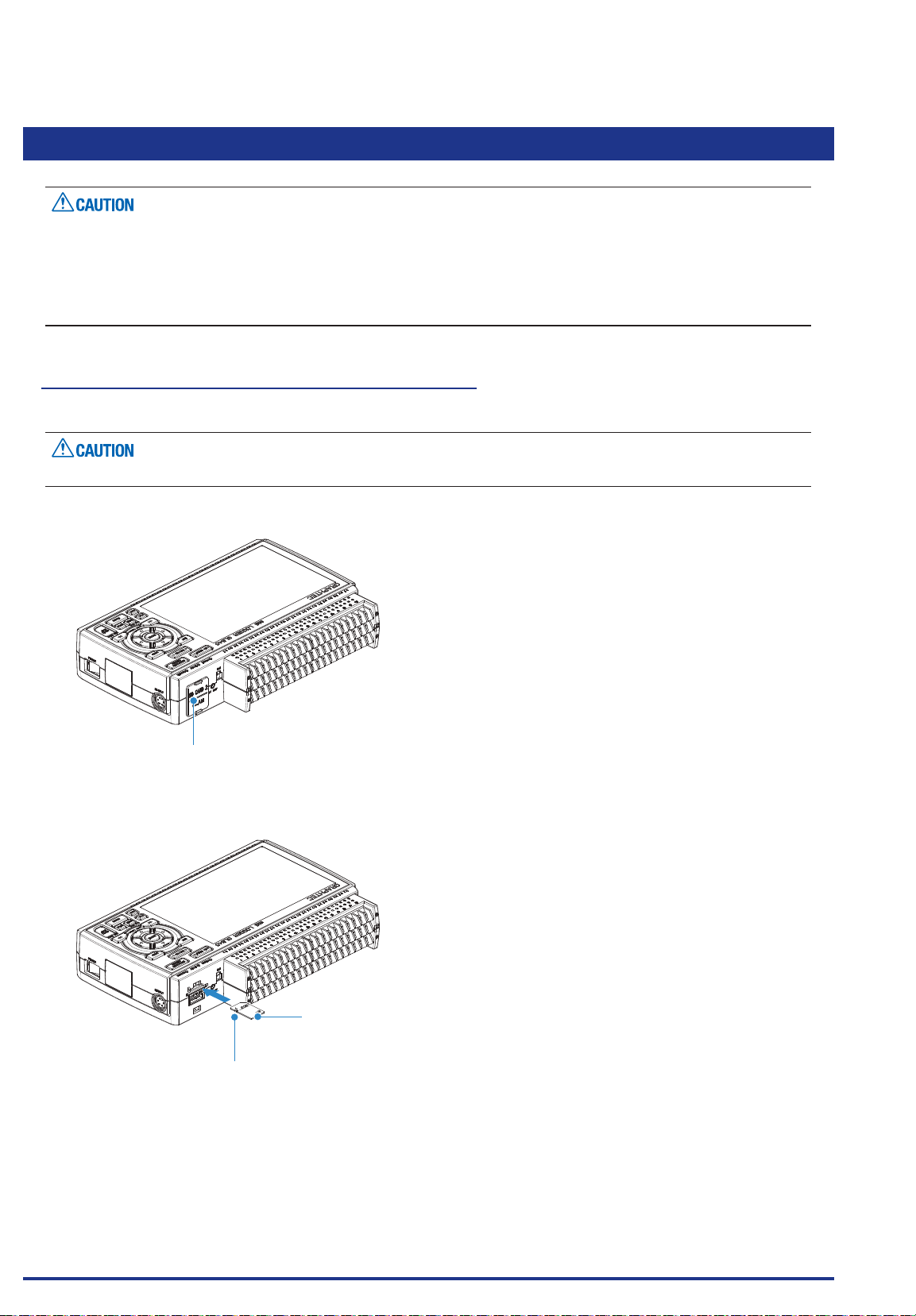
How to insert the SD memory card (SD CARD2)
Insert the SD memory card into the SD CARD2 slot.
When the optional wireless LAN unit is installed, the SD memory card cannot be inserted.
(1) Remove the SD CARD2 protective cover.
Protective cover
(2) Insert the SD memory card until it clicks and is locked.
* Make sure that the SD memory card is not locked.
Lock
SD CARD
x GB
* Make sure that the SD memory card
is not locked.
SD memory card
Find Quality Products Online at: [email protected]
www.GlobalTestSupply.com
2-11
Page 31
CHAPTER 2 Checks and Preparation
(3) Insert and close the protective cover into the upper hole and lower hole for the SD CARD2 protective
cover.
Protective cover
How to remove the SD memory card (SD CARD2)
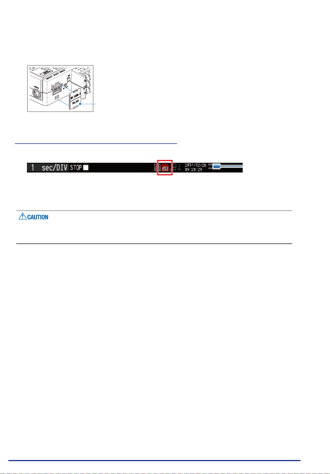
(1) Make sure that the SD memory card displayed on the screen is green, and then remove it.
(2) Open the SD CARD2 protective cover.
(3) The SD memory card is unlocked by pushing gently the SD memory card. Then, remove the SD memory
card.
The SD CARD2 is displayed in red while accessing to the SD memory card (Device Access display is
displayed in "red" and POWER LED is blinking.). Remove the SD memory card only when the SD CARD2 is
displayed in green.
Find Quality Products Online at: [email protected]
www.GlobalTestSupply.com
2-12
Page 32
CHAPTER 2 Checks and Preparation
2.8 Installing the Wireless LAN Unit (B-568: Option)
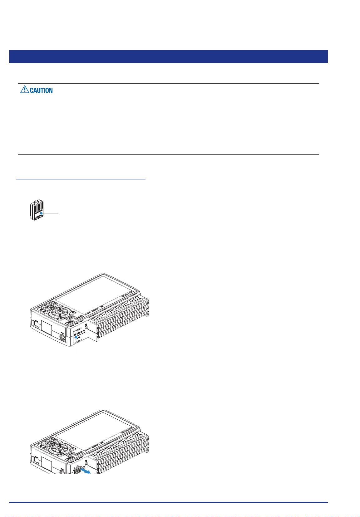
To connect the GL840 to the wireless LAN, insert the wireless LAN unit in the SD CARD2 slot.
When the SD memory card has been inserted into the SD CARD2 slot, please remove the SD memory card.
•
When the wireless LAN unit has been inserted, the SD memory card cannot be inserted into the SD CARD2
•
slot.
When inserting the wireless LAN unit, please make sure that the power is turned OFF and then install the
•
unit.
When using the wireless LAN, please check the "3. Notes on Radio Law" in the “Notes on Use” described
•
above.
How to insert the wireless LAN unit
Insert the wireless LAN unit into the SD CARD2 slot.
Wireless LAN unit
(Option: B-568)
(1) Turn OFF the GL840’s power.
(2) Remove the SD CARD2 protective cover.
* Please keep so as not to lose the SD CARD2 protective cover.
Protective cover
(3) When the SD memory card has been inserted, remove the SD memory card.
* The SD memory card is unlocked by pushing gently the SD memory card. Then, remove the SD
memory card.
Lock
SD CARD
x GB
Find Quality Products Online at: [email protected]
SD memory card
www.GlobalTestSupply.com
2-13
Page 33
CHAPTER 2 Checks and Preparation
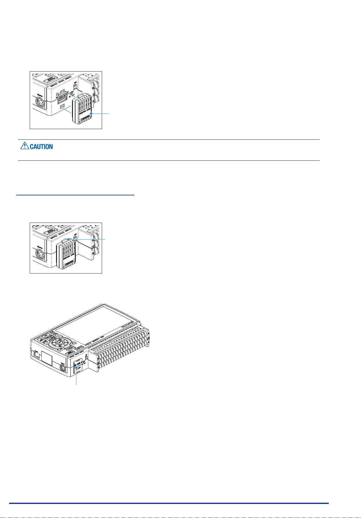
(4) Align the wireless LAN unit to the wireless unit terminal and the wireless unit xed guide and then insert
the wireless LAN unit until the unit is locked.
Wireless LAN unit
When the wireless LAN unit has been inserted, please be careful when handling so as not to hit and drop.
Removing the wireless LAN unit
Turn OFF the power and then remove the wireless LAN unit.
(1) Push the lock part on the wireless LAN unit to unlock, and then remove it.
Lock part
(2) After removing it, mount the SD CARD protective cover to protect the connectors.
Protective cover
Find Quality Products Online at: [email protected]
www.GlobalTestSupply.com
2-14
Page 34
CHAPTER 2 Checks and Preparation
2.9 Connecting to a PC
Use the USB or LAN Interface to connect the GL840 to a PC.
Connection Using a USB Cable
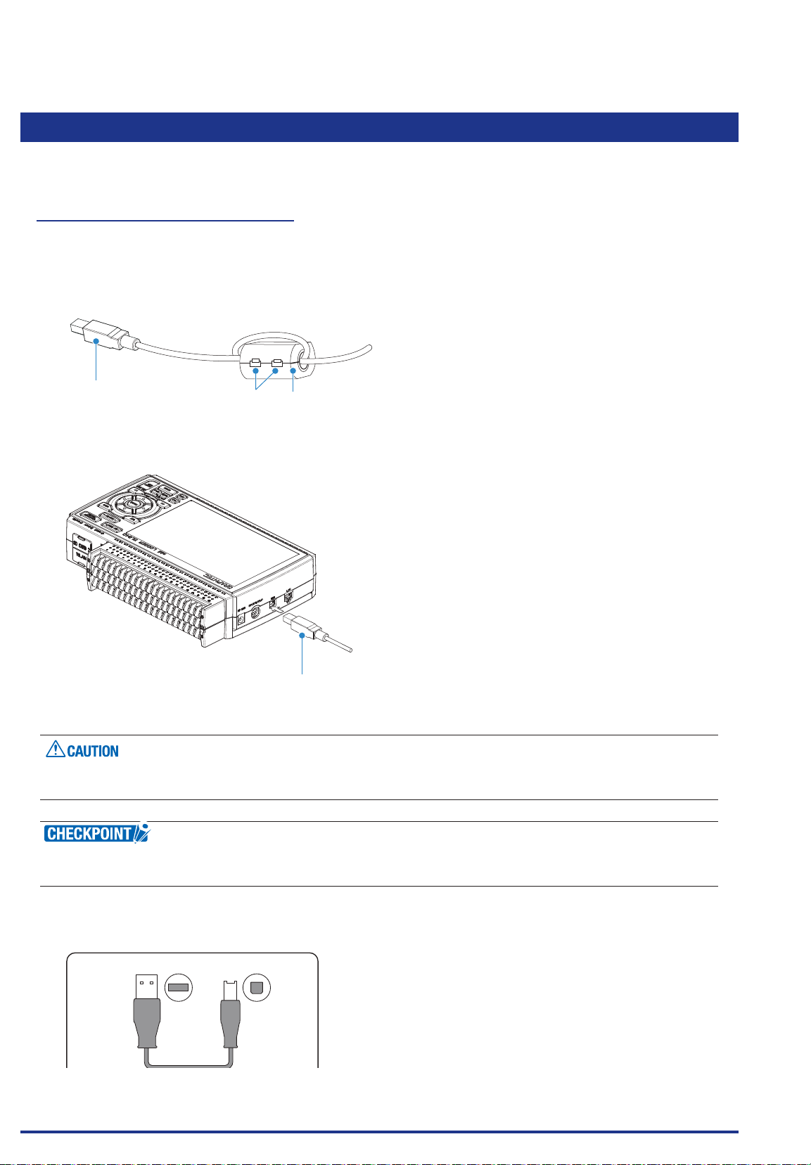
(1) This GL840 complies with the EMC Directive in the state when the supplied ferrite core is attached to the
USB cable.
To connect to the PC with the USB cable, attach the supplied ferrite core to the USB cable as shown in
the following gure.
USB cable
(2) Connect between the GL840 and PC with the USB cable.
The USB connector is adjacent to the LAN connector. Make sure the cable is inserted into the correct
connector.
Ferrite core (Supplied item)Lock part
USB cable
If the USB cable is used, the USB driver must be installed in your PC. Please refer to “USB Driver
Installation Manual” in the supplied CD-ROM for the installation procedure.
Use the cable with A and B connectors to connect the GL840 to a PC.
•
A connector B connector
Find Quality Products Online at: [email protected]
www.GlobalTestSupply.com
2-15
Page 35
CHAPTER 2 Checks and Preparation
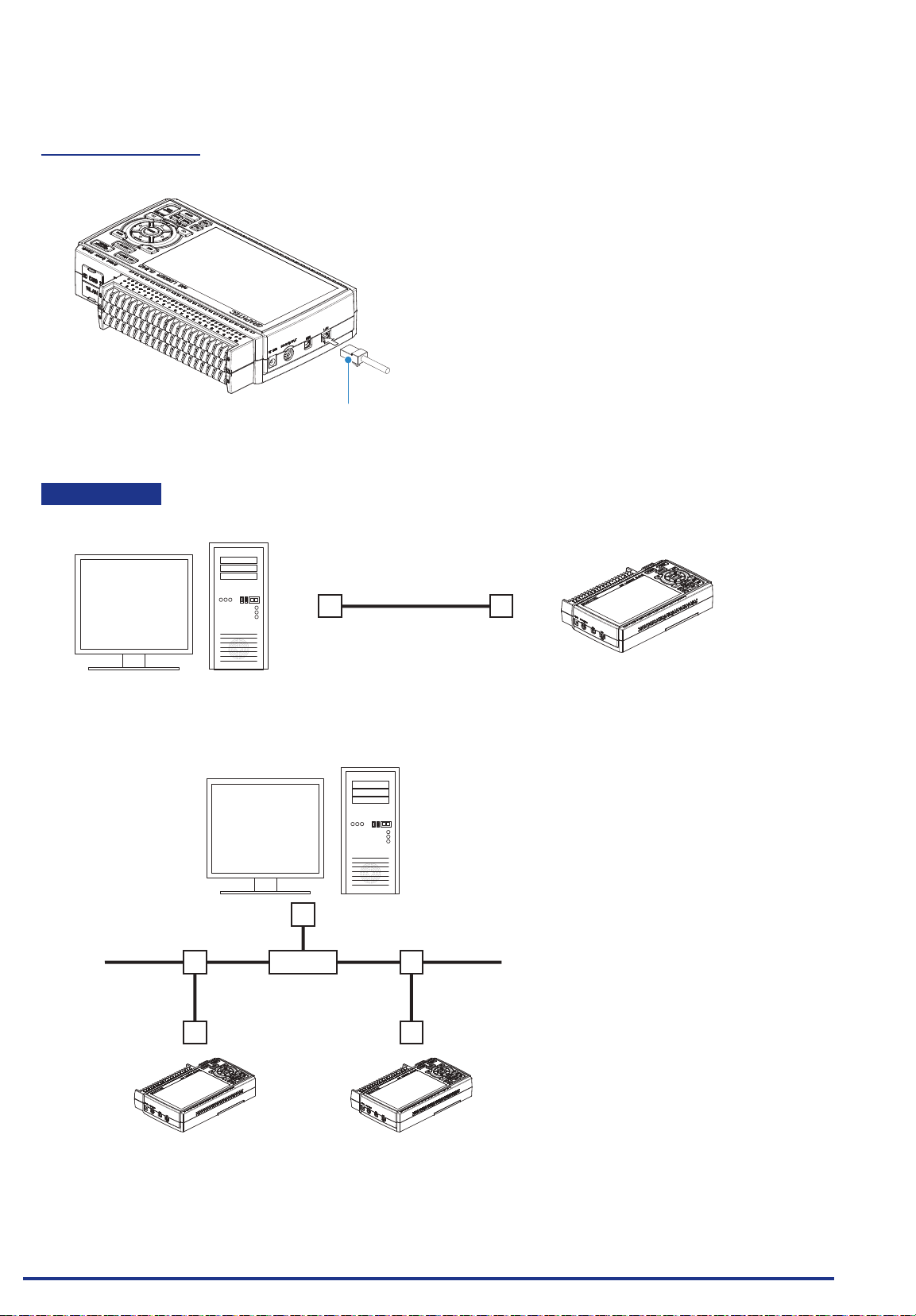
LAN Connection
Use a LAN cable to connect the GL840 to a PC.
Cable Types
• Use a crossing cable when connecting directly to a PC, without using a hub.
LAN cable
LAN cable (crossing)
PC GL840
• Use a straight cable when using a hub.
PC
LAN cable (straight) LAN cable (straight)
GL840GL840
Find Quality Products Online at: [email protected]
www.GlobalTestSupply.com
2-16
Page 36
CHAPTER 2 Checks and Preparation
Connection to the wireless LAN
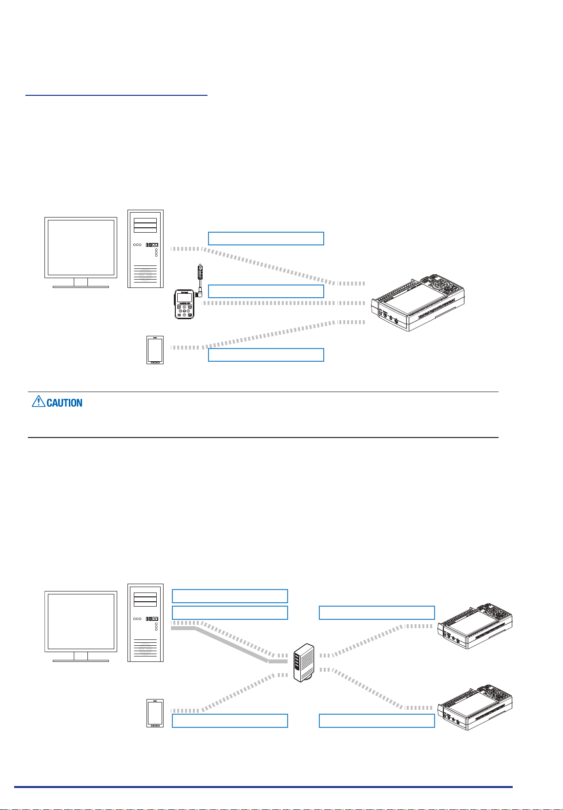
Insert the wireless LAN unit (optional). For the insertion, refer to “2.8 Installing the Wireless LAN Unit (B-568:
Option)”.
1. Access point (operating as a base unit):
When connecting the GL840 to the GL100-WL (up to 5 units) or PC/Smartphone via the wireless LAN,
the following devices and the operating environment are required.
• PC and Smartphone which can connect to the wireless LAN
Wireless connection
PC: Child unit
GL100
Smartphone: Child unit
When the GL100-WL is connected through the wireless LAN, the PC cannot be connected to the GL840
through the wireless LAN.
Wireless connection
GL840: Base unit
Wireless connection
2. Stations (operating as a child unit):
When connecting to the commercially available wireless LAN base unit and controlling multiple GL840s
from PC, the following devices and the operating environment are required.
• PC and Smartphone which can connect to the wireless LAN with the dedicated software
• Wireless LAN base unit (equipped with the functions of Wi-Fi authenticated wireless LAN base unit.)
• Internet environment for Internet connection (Internet provider’s contracts and mobile carrier’s
contracts)
• Internet connection and e-mail send/receive environment (Internet provider and Web mail, etc.) when
sending/receiving e-mail.
Wireless connection
Wire-line connection
PC: Child unit
Base unit
Wireless connection Wireless connection
Smartphone: Child unit
Find Quality Products Online at: [email protected]
www.GlobalTestSupply.com
Wireless connection
GL840: Child unit
GL840: Child unit
2-17
Page 37
CHAPTER 2 Checks and Preparation
2.10 Using the Battery Pack (B-569 : Option)
The B-569 (optional) is the only battery type that can be used with the GL840.
•
Refer to the specications (Page 4-11) for information on the battery run time.
•
The operating temperature ranges of the GL840 with a battery pack mounted are as follows:
•
Running on battery : 0 to 40°C
Battery being charged : 15 to 35°C
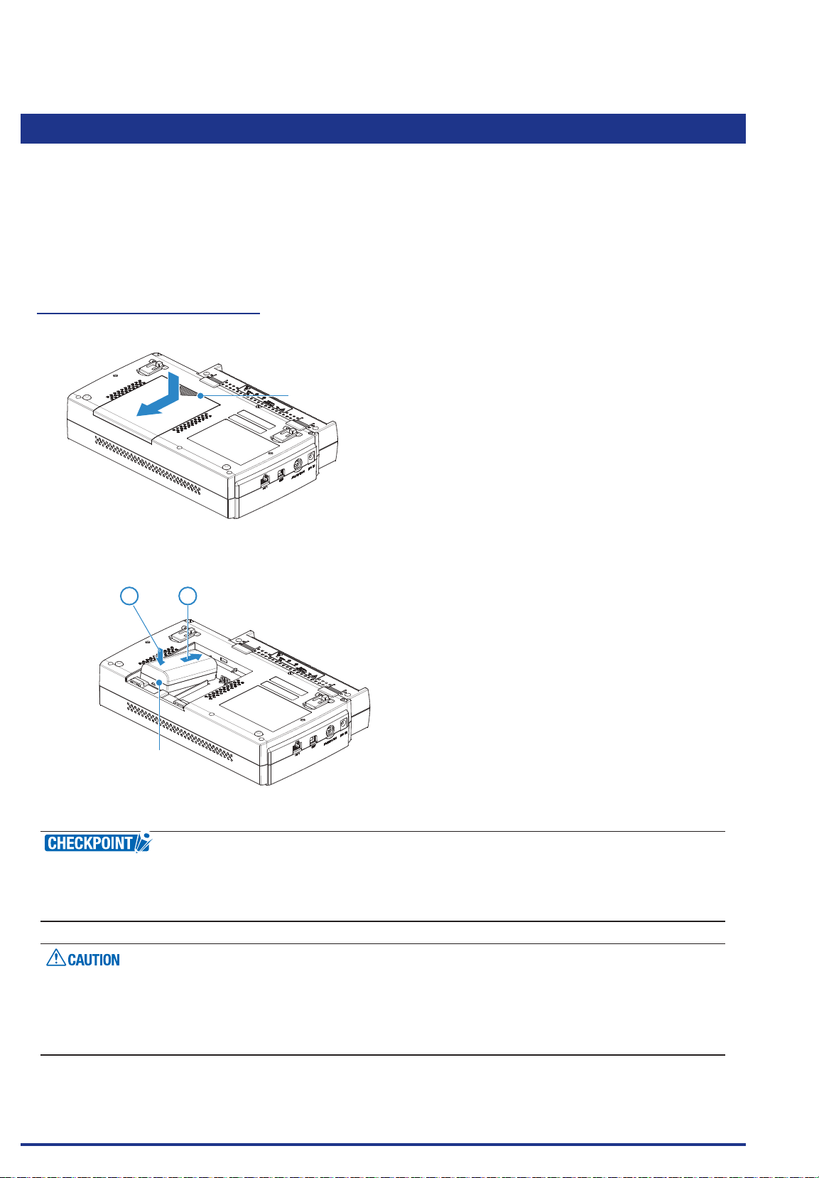
Mounting the Battery Pack
(1) While lightly pushing the grip of the battery cover, slid the cover in the direction indicated by the arrow.
Grip
(2) Attach the battery pack (B-569).
12
Battery pack
Either one or two battery packs can be attached.
•
To connect one pack, connect to either one of the connectors.
•
Attaching two battery packs allows longer operational time.
•
When attaching two battery packs, make sure the battery levels are equivalent.
•
Do not use a new battery with an old battery at the same time.
•
When attaching two battery packs, make sure the remaining amount are same.
•
If you are not sure about the amount, charge each battery and then attach full-charged two battery packs.
•
Find Quality Products Online at: [email protected]
2-18
www.GlobalTestSupply.com
Page 38
CHAPTER 2 Checks and Preparation
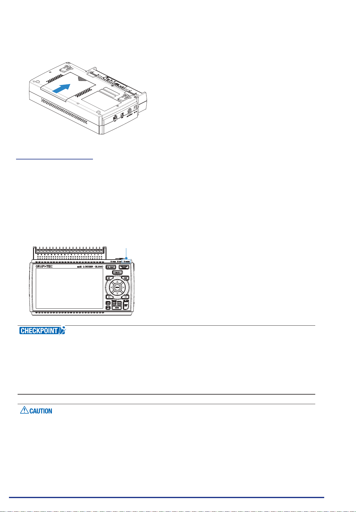
(3) Attach the battery cover.
Charging the Battery
Expected time required for charging:
Battery pack x 1: approx. 5 hours
•
Battery pack x 2: approx. 10 hours
•
The battery pack is charged by mounting it in the GL840, attaching AC adapter to the GL840.
(1) Mount the battery pack in the GL840 (see "Mounting the Battery Pack" in the previous page for the
mounting procedure.).
(2)
Turn on the power to the GL840. (Please see "2.4 Connecting the Power Cable and Turning on the Power").
(3) The CHARGE LED lights.
CHARGE LED
GL840 is equipped with a temperature monitor function which starts automatic charging as soon as
•
it is cooled down. Therefore, depending on the internal temperature, charging may not be performed
immediately.
The operating temperature range during charge is from 15 to 35°C.
•
When charging is attempted while the power is ON, charging may not be performed immediately even if
•
the temperature environment conforms to the specication. In such a case, set the Screen Saver settings
to ON or perform charging while the power is OFF.
During data capture, when the battery capacity is lower, the le is closed automatically.
•
When using with the AC adapter, the GL840 is automatically battery-powered in case of power outage.
•
During the power is supplied directly from the DC power without using the AC adapter, when the DC
•
voltage is 16V or less, the battery charge is disabled.
The running time depends on the operating environment.
•
When the empty battery is charged in the GL220/820/900, the charging in about 80-90% will stop. Once
disconnect and connect the AC adapter, or remove and insert the battery pack. The battery pack charging
Find Quality Products Online at: [email protected]
is started in order to charge up to 100%. (It depends on the remaining capacity.)
www.GlobalTestSupply.com
2-19
Page 39
CHAPTER 2 Checks and Preparation
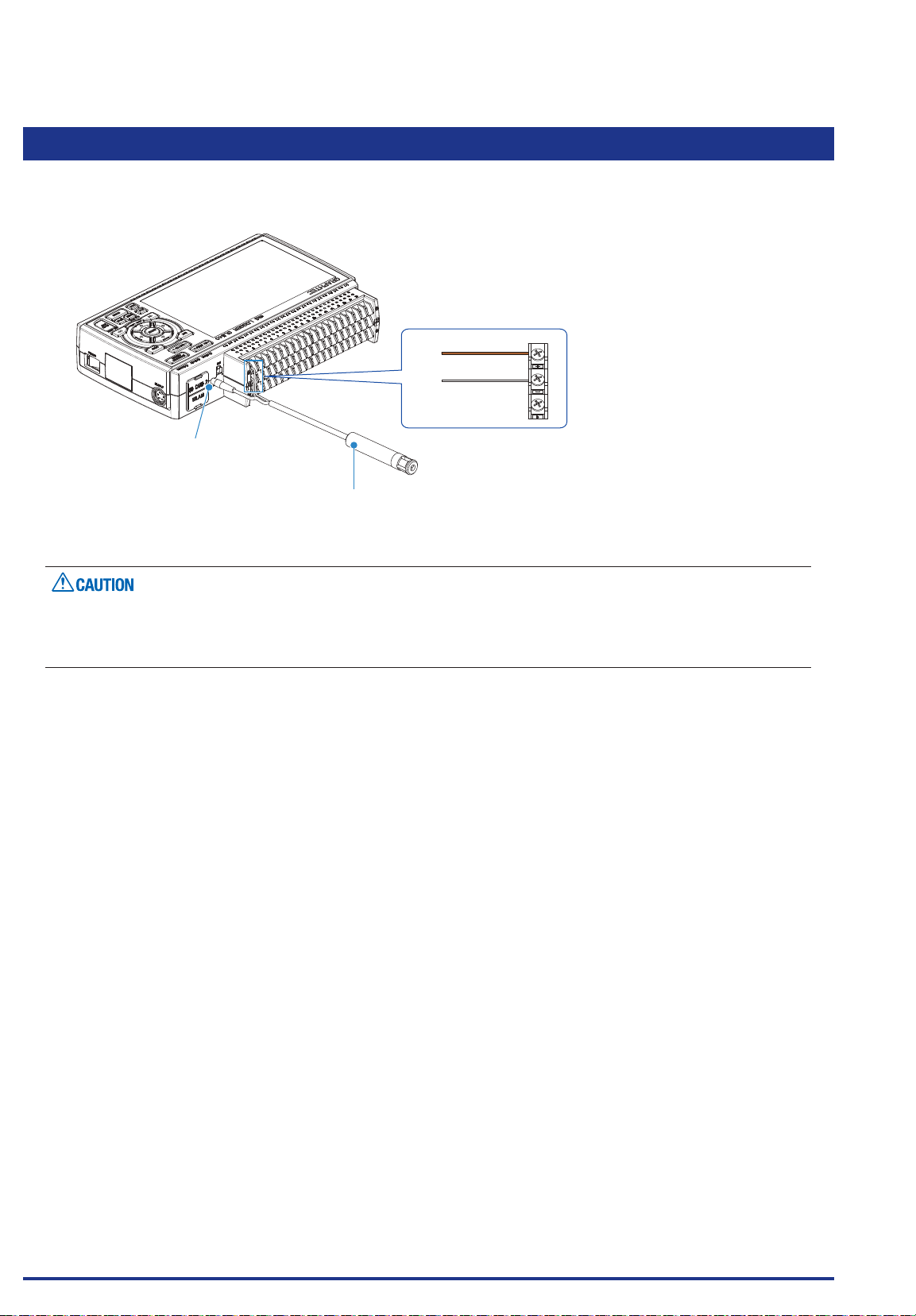
2.11 Connecting the Humidity Sensor (Optional)
Connect the + and - lead wires of the humidity sensor (the B-530: Option) to the desired terminals, and then
insert the round connector into the 5V OUT connector on the GL840.
Brown
Humidity Sensor
White
Connected to the 5V OUT
terminal.
Humidity sensor
(B-530: Option)
Do not use the sensor in a strong electrolyte envronment. Measured results may not satisfy to the stated.
•
The optional humidity sensor power BOX (B-542) is required to use 2 to 10 humidity sensors.
•
5V OUT terminal on the GL840 is available for only one humidity sensor.
•
+
-
Find Quality Products Online at: [email protected]
2-20
www.GlobalTestSupply.com
Page 40
CHAPTER 2 Checks and Preparation
2.12
Mounting and Removing the Standard Terminal and Withstand high-voltage high-precision Terminal
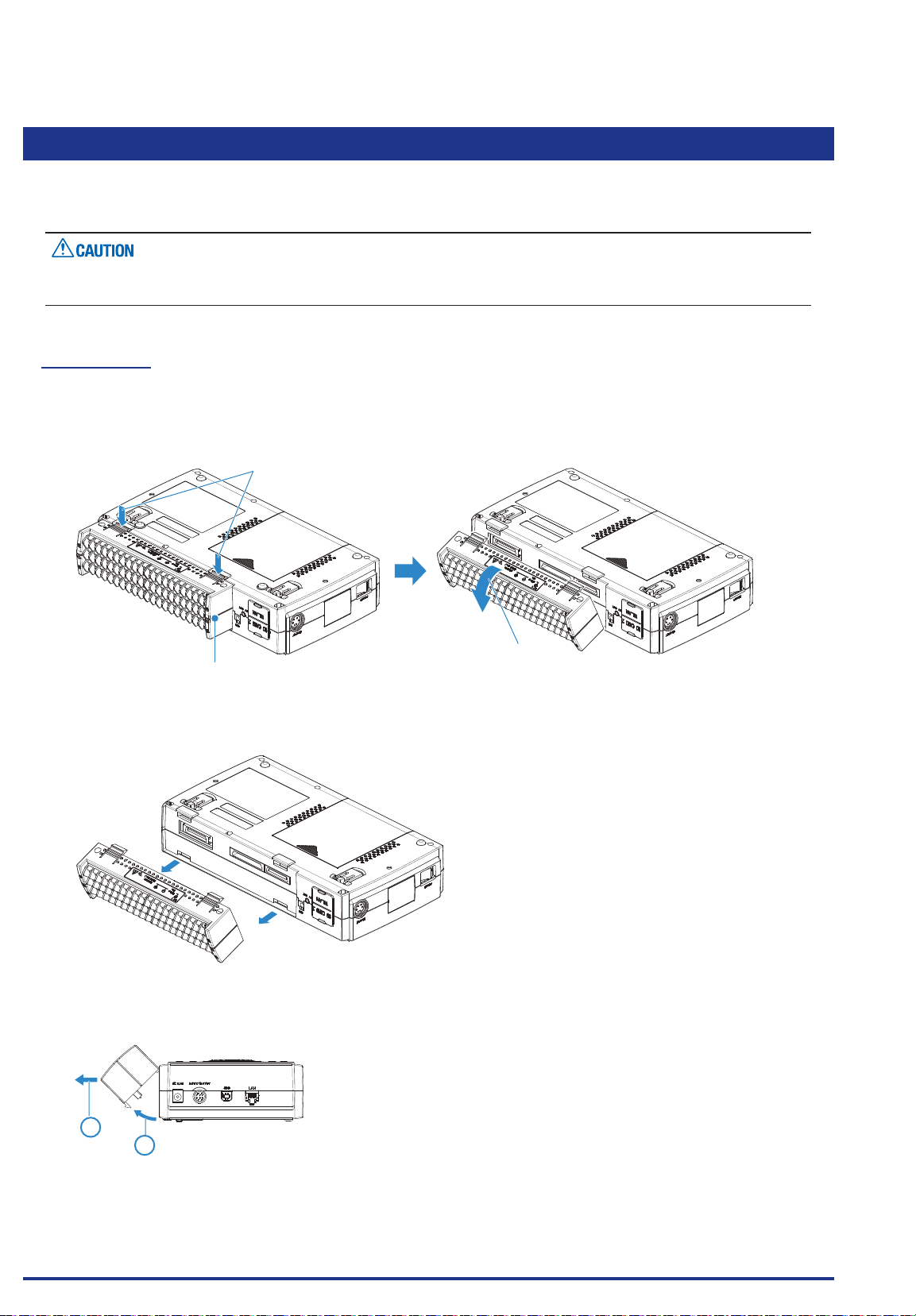
The mounting and removing procedure of the standard terminal and Withstand high-voltage high-precision
terminal is described blow.
When mounting or removing the standard terminal or Withstand high-voltage high-precision terminal,
please make sure that the GL840’s power is turned OFF.
To Remove
Pull out the terminal in the direction of the arrow while pressing the lock portions (2 places) at the bottom of
the standard terminal or the Withstand high-voltage high-precision terminal.
(1) Press the two lock portions in the direction indicated by arrows.
Lock portion
Pull out
Terminal unit
(2) Pull the terminal unit out towards the direction indicated by the arrow.
Pull the terminal unit out as shown in the following gure.
Top
2
1
Find Quality Products Online at: [email protected]
Bottom
www.GlobalTestSupply.com
2-21
Page 41
CHAPTER 2 Checks and Preparation
To Mount
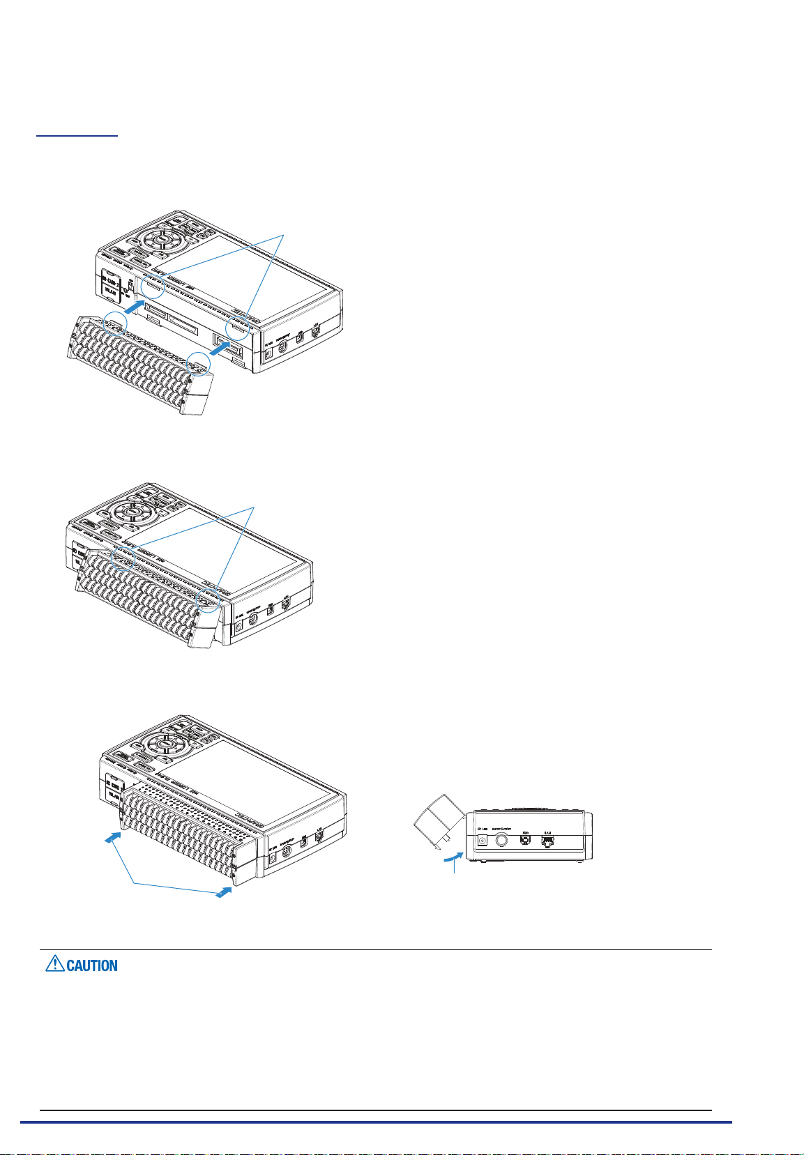
Insert the lock tabs at the top of the standard terminal or the Withstand high-voltage high-precision terminal
into the slots of the GL840, and push in the terminal until the lock tabs at the bottom of the terminal are
securely locked.
Slot
(1) Insert tabs at the top of the terminal unit into the slots.
Insert
(2) Press the terminal unit in the direction shown until it is securely locked.
Press
Press
If the terminal unit that comes with the standard GL800 is mounted on the GL840, the temperature
•
measurement accuracy may not meet the specications.
If the terminal unit that comes with the standard GL820 is mounted on the GL840, the temperature
•
measurement accuracy may not meet the specications.
The standard terminal and Withstand high-voltage high-precision terminal specications are different.
•
Find Quality Products Online at: [email protected]
Please check the specications when using them.
The Withstand high-voltage high-precision terminal is not available for the GL800 and GL820.
•
2-22
www.GlobalTestSupply.com
Page 42
CHAPTER 2 Checks and Preparation
2.13
Mounting the Extension Terminal Base (Optional ) an d Extension Terminal Cable ( Optiona l )
2.13.1 Mounting the extension terminal base
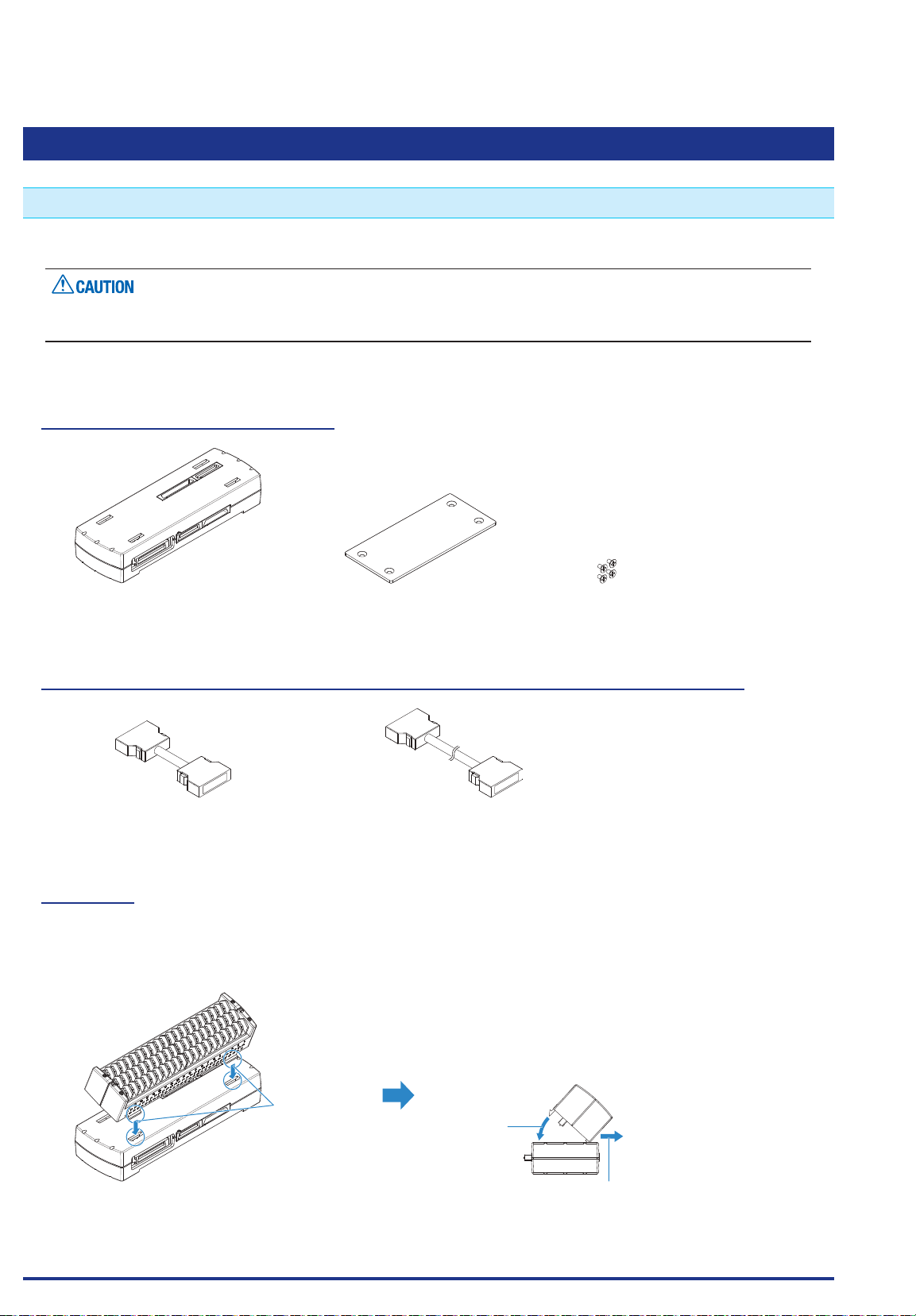
Mount the extension terminal base set as shown below.
When mounting the extension terminal base on the GL840, please make sure that the GL840’s power is
turned OFF.
Prepare the sold separately extension terminal base and the extension terminal connection cable.
B-566 Extension Terminal Base
Extension terminal base: 1 unit Connection plate: 1 pc. M4 x 6 at-head screw: 4 pcs.
B-567 Extension terminal connection cable (Select from two types of cables)
Extension terminal connection cable
(50 cm: B-567-05): 1 pc.
Extension terminal connection cable
(2 m: B-567-20): 1 pc.
To Mount
(1) Remove the standard terminal or Withstand high-voltage high-precision terminal mounted on the GL840.
(2) Insert the lock tabs at the top of the terminal into the slots of the extension terminal base, and press the
terminal until the lock tabs at the bottom of the terminal are securely locked.
Insert
Press
* When installing the Withstand high-
voltage high-precision terminal
Find Quality Products Online at: [email protected]
www.GlobalTestSupply.com
(B-565),please push it while pulling
to the front.
2-23
Page 43
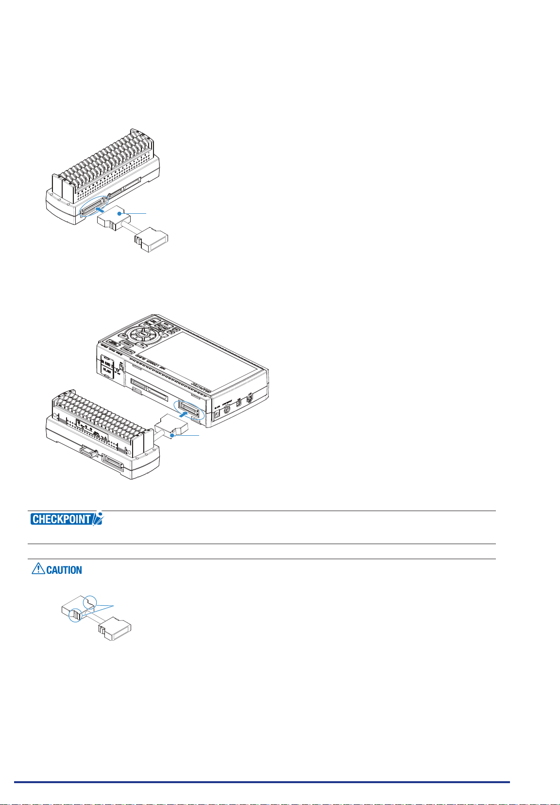
CHAPTER 2 Checks and Preparation
(3) Connect the extension terminal connection cable to the extension terminal base.
* Insert the extension terminal connection cable until the cable is securely locked.
* Connect in accordance with the connector shape.
Extension terminal connection cable
(4) Connect one end of the extension terminal connection cable to the terminal connector on the GL840.
* Insert the extension terminal connection cable until the cable is securely locked.
Extension terminal connection cable
When one terminal unit (20ch) is mounted, the connecting plate and at-head screw are not used.
How to Remove the expansion terminal connection cable
•
Lock release lever
When you want to remove the expansion terminal connection cable from the GL840 or extension terminal
base, please note the following.
Always press the both sides of the lock release lever and pull out straightly in a state where the lock is
•
released.
Please do not forcibly remove or do not pull out in a state where the lock is not released by pressing only
•
the one side of the lock release lever.
It may cause a connection failure of connector, please be careful when you remove it.
Find Quality Products Online at: [email protected]
2-24
www.GlobalTestSupply.com
Page 44
CHAPTER 2 Checks and Preparation
2.13.2 Mounting multiple extension terminals
The mounting procedure of the multiple extension terminal set is described.
Make sure the GL840’s power is OFF when mounting the extension terminals on the GL840.
Prepare the sold separately extension terminal base and extension terminal connection cable.
B-566 Extension terminal base
Prepare the number of extension terminal bases that is equal to the number that the standard terminal or the
Withstand high-voltage high-precision terminal is added.
B-567 Extension terminal connection cable (Select from two types of cables)
Prepare one of the two types of extension terminal connection cables (50 cm: B-567-05 or 2 m: B-567-20).
Also, when you want to connect away between the extension terminal bases, the required number of the
extension terminal bases must be prepared.
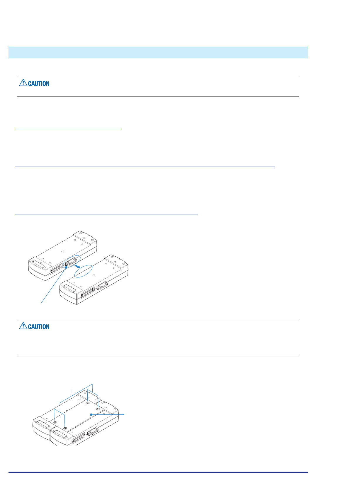
When direct-connecting the extension terminal bases
(1) Connect the extension terminal base unit connectors as shown below.
* Please direct-connect to the protruding parts carefully.
Please direct-connect the extension terminal bases carefully so as not to bend the protruding parts next to
•
the connector.
Please handle the connection plate in a horizontal state Until the connection plate is xed.
•
(2) Fix the connection plate using attached screws.
* Recommended screw torque: 14 kgf/cm
M4 x 6 at he ad screws
Connection plate
Find Quality Products Online at: [email protected]
www.GlobalTestSupply.com
2-25
Page 45
CHAPTER 2 Checks and Preparation
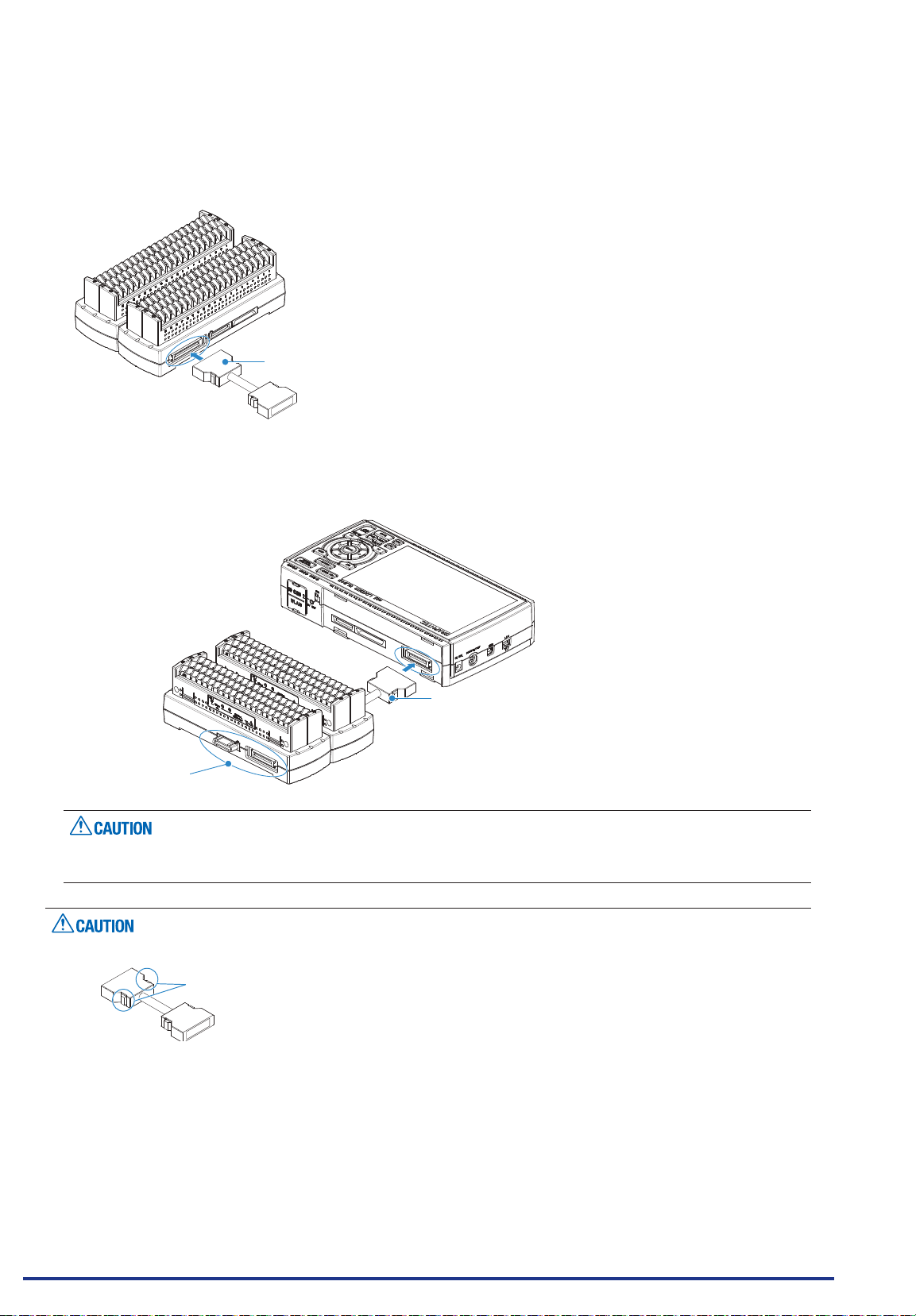
(3) Connect the extension terminal connection cable to the extension terminal base.
* Insert the cable connector until it is securely locked.
* Connect in accordance with the connector shape.
(4) Connect one end of the extension terminal connection cable to the GL840.
* Insert the cable connector until it is securely locked.
Extension terminal connection cable
Extension terminal connection cable
Do not touch.
While the signal is input to the direct-connected terminal, please do not touch the connector pins and
the protruding part next to the connector.
How to Remove the expansion terminal connection cable
•
Lock release lever
When you want to remove the expansion terminal connection cable from the GL840 or extension terminal
base, please note the following.
Always press the both sides of the lock release lever and pull out straightly in a state where the lock is
•
released.
Please do not forcibly remove or do not pull out in a state where the lock is not released by pressing only
•
the one side of the lock release lever.
It may cause a connection failure of connector, please be careful when you remove it.
Find Quality Products Online at: [email protected]
www.GlobalTestSupply.com
2-26
Page 46
CHAPTER 2 Checks and Preparation
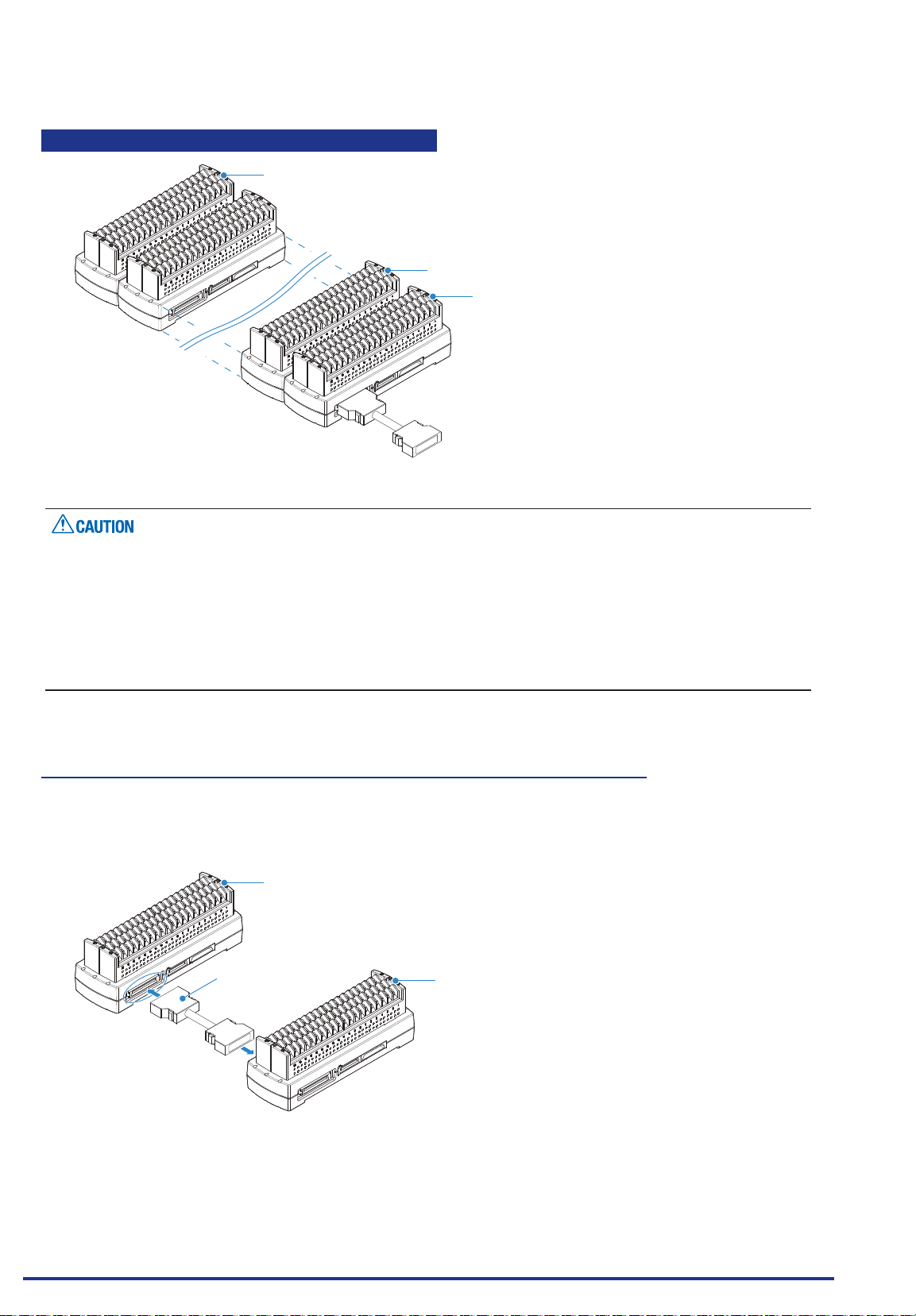
When adding the extension terminal bases
Unit 10 (CH 181 to 200)
Unit 2 (CH 21 to 40)
Unit 1 (CH 1 to 20)
When the terminals are added, please connect continuously them without disconnected terminals. If there
•
is a disconnected terminal, subsequent terminals are not recognized.
When the combination of the standard terminal and Withstand high-voltage high-precision terminal is
•
used, the withstand voltage specication of standard terminal is applied.
When the terminal of the GL800 or the GL820 is used, or the combination of the GL800 and the GL820 is
•
used, the temperature measurement accuracy may not satisfy the specication.
The Withstand high-voltage high-precision terminal is not available for the GL800 and GL820.
•
When direct-connecting with extension terminal connection cable
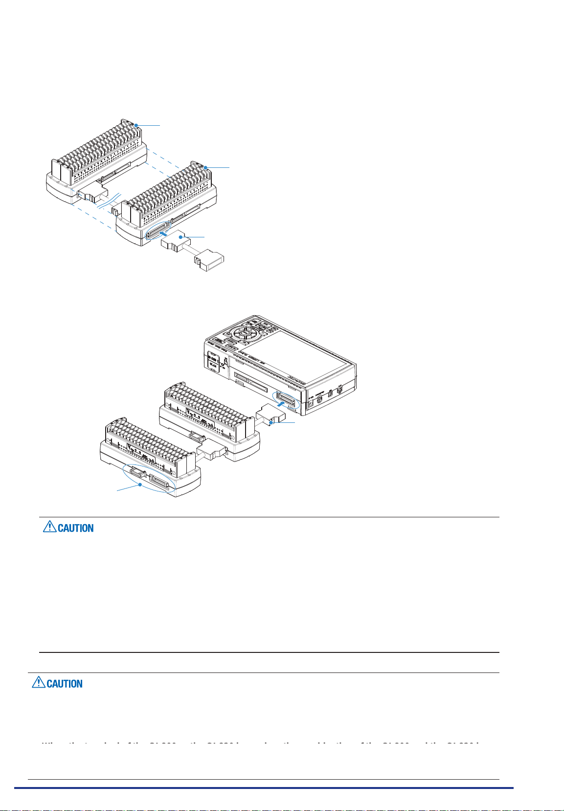
(1) Connect between the extension terminal bases with the extension terminal connection cable.
* Insert the extension terminal connection cable until the cable is securely locked.
* Connect in accordance with the connector shape.
Unit 2 (CH21 to CH40)
Extension terminal
connection cable
Unit 1 (CH1 to CH20)
Find Quality Products Online at: [email protected]
www.GlobalTestSupply.com
2-27
Page 47
CHAPTER 2 Checks and Preparation
(2) Connect each between the extension terminal bases with the extension terminal connection cable.
* Insert the extension terminal connection cable until the cable is securely locked.
Install the extension terminal bases in a stable location and be careful not to fall.
Unit 2 (CH21 to CH40)
(3) Connect one end of the extension terminal connection cable to the GL840.
* Insert the extension terminal connection cable until the cable is securely locked.
Unit 1 (CH1 to CH20)
Extension terminal connection cable
Extension terminal connection cable
Extension terminal connection cable
Do not touch.
While the signal is input to the direct-connected terminal, please do not touch the connector pins and
•
terminal next to the connector.
When removing the extension terminal connection cable from the GL840 or the extension terminal base,
•
please note the following:
• Please always pull out straightly in a state where the both sides of the lock release lever are pushed.
• Please do not forcibly remove or do not pull out in a state where only the one side of the lock release
lever is pushed.
It may cause a connection failure of connector, please be careful when you remove it.
When the extension terminal cable is used, it becomes susceptible to noise.
•
If the cable is affected by the noise, please slow down the sampling speed.
When the terminals are added, please connect continuously them without disconnected terminals. If there
•
is a disconnected terminal, subsequent terminals are not recognized.
When the combination of the standard terminal and Withstand high-voltage high-precision terminal is
•
used, the withstand voltage specication of standard terminal is applied.
When the terminal of the GL800 or the GL820 is used, or the combination of the GL800 and the GL820 is
•
Find Quality Products Online at: [email protected]
used, the temperature measurement accuracy may not meet the specication.
The Withstand high-voltage high-precision terminal is not available for the GL800 and GL820.
•
www.GlobalTestSupply.com
2-28
Page 48
CHAPTER 2 Checks and Preparation
2.14 Precautions to Observe When Performing Measurement
Do not apply radio-frequency signals with high voltage (50 KHz or above).
•
Be sure to use only the AC adapter provided as a standard accessory. The rated power supply range for
•
the adapter is 100 to 240 VAC, and the rated frequency is 50/60 Hz. Do not use any other voltages.
Do not input the voltage that is exceeding the specication of this device.
•
· If a voltage exceeding the specied value is input, the semiconductor relay in the input section will be
damaged. Never input a voltage exceeding the specied value even for a moment. It will cause the re.
· Have an enough margin from the specication of withstanding voltage when using this device, it have to
consider a noise and change of the measurement voltage.
· Conrm this device is not broken before the input cable is connected to the input terminal.
· Please take care of the static electricity when the connecting the input cables or the thermocouples.
· Do not touch the tip of thermocouples with bare hand after the thermocouples are connected to the
terminal of this device when the tip of thermocouples is not insulated.
The static electricity of a human body will cause damage to this device.
· Do not put the tip of thermocouples to the object which is containing the static electricity when the tip of
thermocouples is not insulated. The static electricity of object will cause damage to this device.
· Do not put the tip of thermocouples to the object which is containing the leaked high voltage of chassis
or metal etc. when the tip of thermocouples is not insulated.
The leaked high voltage of object will cause damage to this device.
· We recommend that the insulation tape puts on the tip of thermocouples before connecting the
thermocouples to the input terminals.
This will protect this device from the static electricity and the leaked high voltage.
* This applies to all the channels even if channel extension is used.
* The specication of all channels becomes the B-564, when the B-564 and the B-565 are installed.
Find Quality Products Online at: [email protected]
www.GlobalTestSupply.com
2-29
Page 49
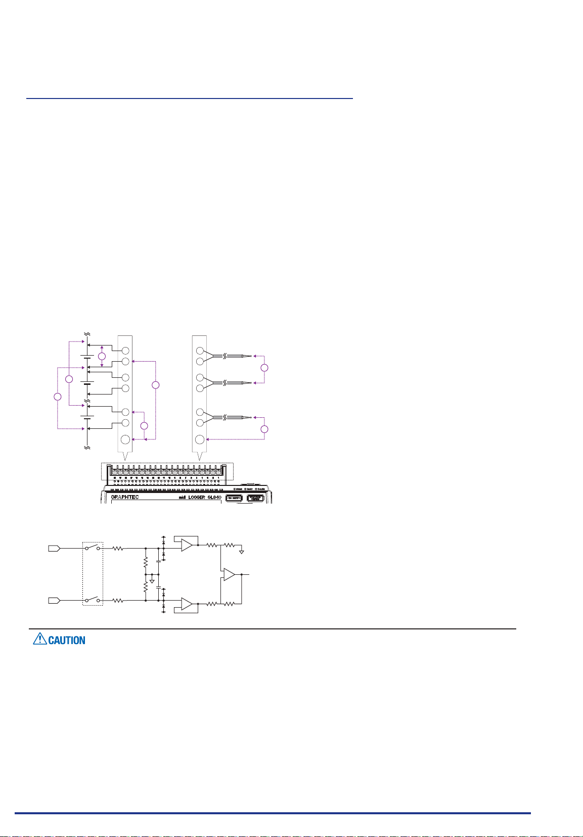
CHAPTER 2 Checks and Preparation
When using the standard terminal (GL840-M and B-564)
Please be sure to read the following carefully in order to prevent electric shocks or shorts.
Maximum input voltage
•
If a voltage exceeding the specied value is input, the semiconductor relay in the input section will be
damaged. Never input a voltage exceeding the specied value even for a moment.
* This applies to all the channels even if channel extension is used.
< Between +/– terminals (A) >
• Maximum input voltage : 60Vp-p (Range of 20mV to 2V)
110Vp-p (Range of 5V to 100V)
<Between input terminal/input terminal (B) >
Maximum input voltage : 60Vp-p
Withstand voltage : 350Vp-p at 1 minute
<Between input terminal/GND (C) >
Maximum input voltage : 60Vp-p
Withstand voltage : 350Vp-p at 1 minute
[ Voltage measuring ]
[ Temperature measuring ]
+
A
-
B
B
Input Circuit Diagram for Analog Input (Voltage, Thermocouples)
•
+
-
Channel Switching Relay
+
C
-
+
-
C
GND
50Ω
500kΩ
500kΩ
50Ω
0.05μF
0.05μF
+
-
+
-
+
-
GND
Thermocouple
Thermocouple
Thermocouple
B
C
Capacitors have been incorporated into the input circuit to increase the noise elimination capability.
After voltage measurement, when the inputs have been disconnected, there will still be some electric
charge remaining.
Before starting another measurement operation, short-circuit the + and - terminals to enable self-
discharge.
The GL840 has a scan system.
While in the status (open) in which signals are not input to the input terminal, measured results may be
inuenced by signals from other channels. In such a case, turn OFF the input setting or short circuit +/-.
If signals are input correctly, measured results are not inuenced by other channels.
Find Quality Products Online at: [email protected]
www.GlobalTestSupply.com
2-30
Page 50
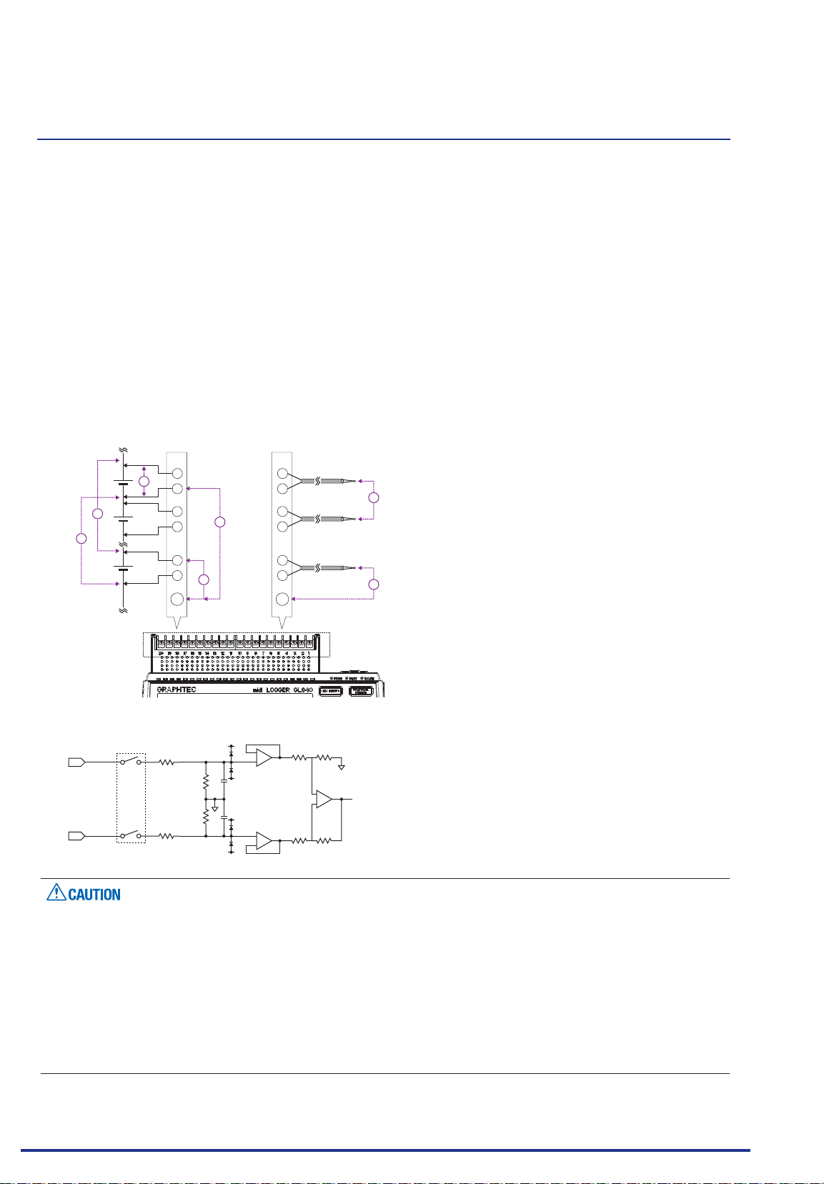
CHAPTER 2 Checks and Preparation
When using the Withstand high-voltage high-precision terminal (GL840-WV and B-565)
Maximum input voltage
•
If a voltage exceeding the specied value is input, the semiconductor relay in the input section will be
damaged. Never input a voltage exceeding the specied value even for a moment.
* This applies to all the channels even if channel extension is used.
< Between +/– terminals (A) >
• Maximum input voltage : 60Vp-p (Range of 20mV to 2V)
110Vp-p (Range of 5V to 100V)
<Between input terminal/input terminal (B) >
Maximum input voltage : 600Vp-p
Withstand voltage : 600Vp-p
<Between input terminal/GND (C) >
Maximum input voltage : 300Vp-p
Withstand voltage : 2300VACrms at 1 minute
[ Temperature measuring ][ Voltage measuring ]
Thermocouple
+
A
-
B
B
+
C
-
+
-
C
+
-
+
-
+
-
Thermocouple
Thermocouple
B
C
GND
Input Circuit Diagram for Analog Input (Voltage, Thermocouples)
•
+
-
50Ω
500kΩ
500kΩ
50Ω
0.05μF
0.05μF
GND
Capacitors have been incorporated into the input circuit to increase the noise elimination capability.
After voltage measurement, when the inputs have been disconnected, there will still be some electric
charge remaining.
Before starting another measurement operation, short-circuit the + and - terminals to enable self-
discharge.
The GL840 has a scan system.
While in the status (open) in which signals are not input to the input terminal, measured results may be
inuenced by signals from other channels.In such a case, turn OFF the input setting or short circuit +/-.
If signals are input correctly, measured results are not inuenced by other channels.
Find Quality Products Online at: [email protected]
www.GlobalTestSupply.com
2-31
Page 51
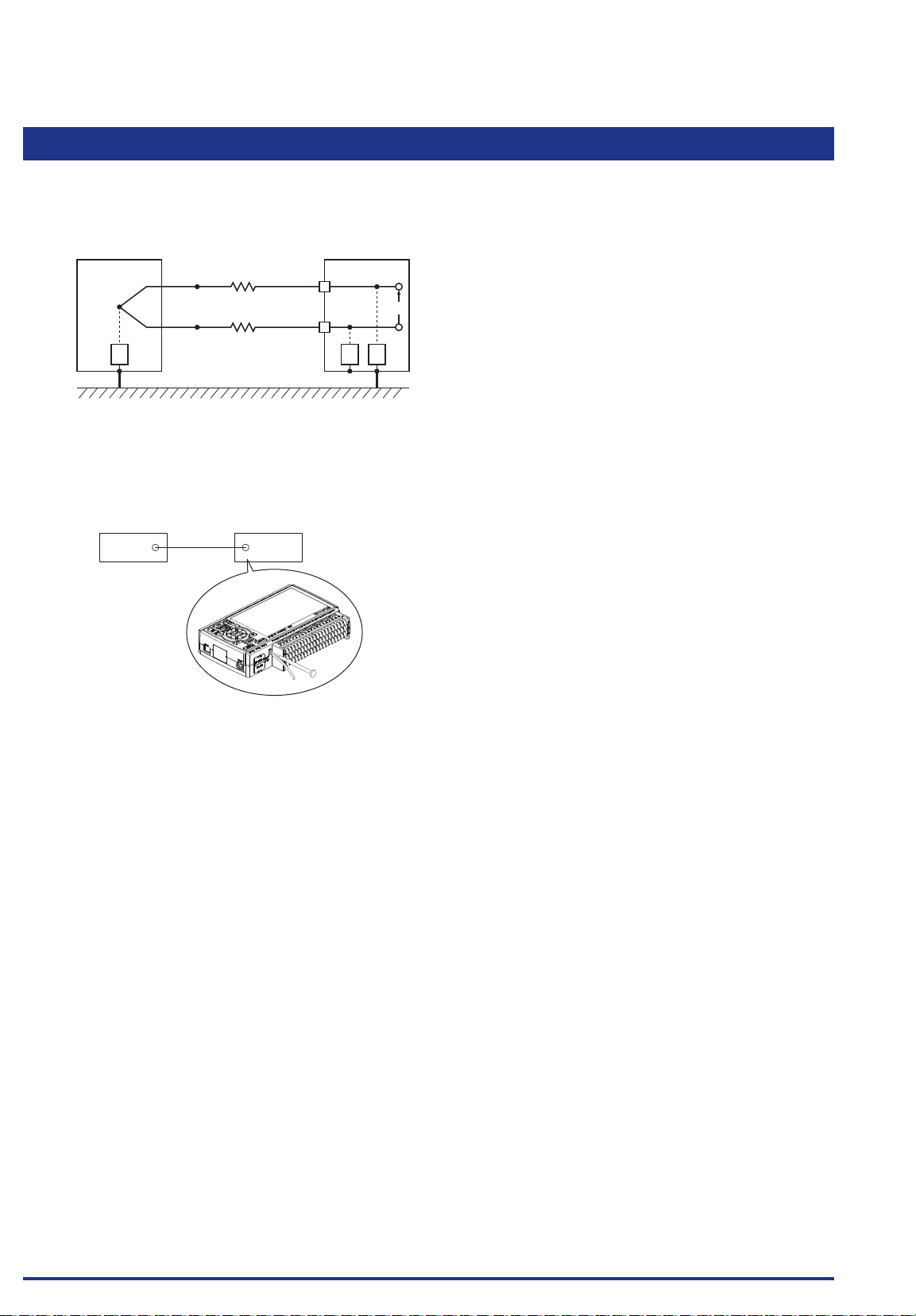
CHAPTER 2 Checks and Preparation
2.15 Noise Countermeasures
Be sure to connect the chassis GND of the measurement object.
•
It may become effective by ensuring that the chassis GND wire of the measurement object is connected
to a good ground.
Measurement object
Thermocouple Input terminals
Z3
Connect the signal chassis GND to the measurement device chassis ground.
•
Use a short, thick lead to connect the chassis GND of the measurement object to the GL840’ chassis
GND. It will become even more effective if the ground potentials are the same.
Measurement device chassis
GND GND
R1
R2
GL840
GL840
+
Vin
-
Z1 Z2
Noise countermeasures
•
If measured values uctuate due to extraneous noise, conduct the following countermeasures.
(Results may differ according to noise type.)
Ex 1 : Connect the GL840’s GND to ground.
Ex 2 : Connect GL840’s GND to measurement object’s GND.
Ex 3 : In the AMP settings menu, set lter to any setting other than “OFF”.
Ex 4 : Set the sampling interval which enables GL840’s digital lter.
Use the “OTHER” menu to set the commercial power frequency you use.
Refer to "3.4 Setting Menus" for details.
Find Quality Products Online at: [email protected]
www.GlobalTestSupply.com
2-32
Page 52
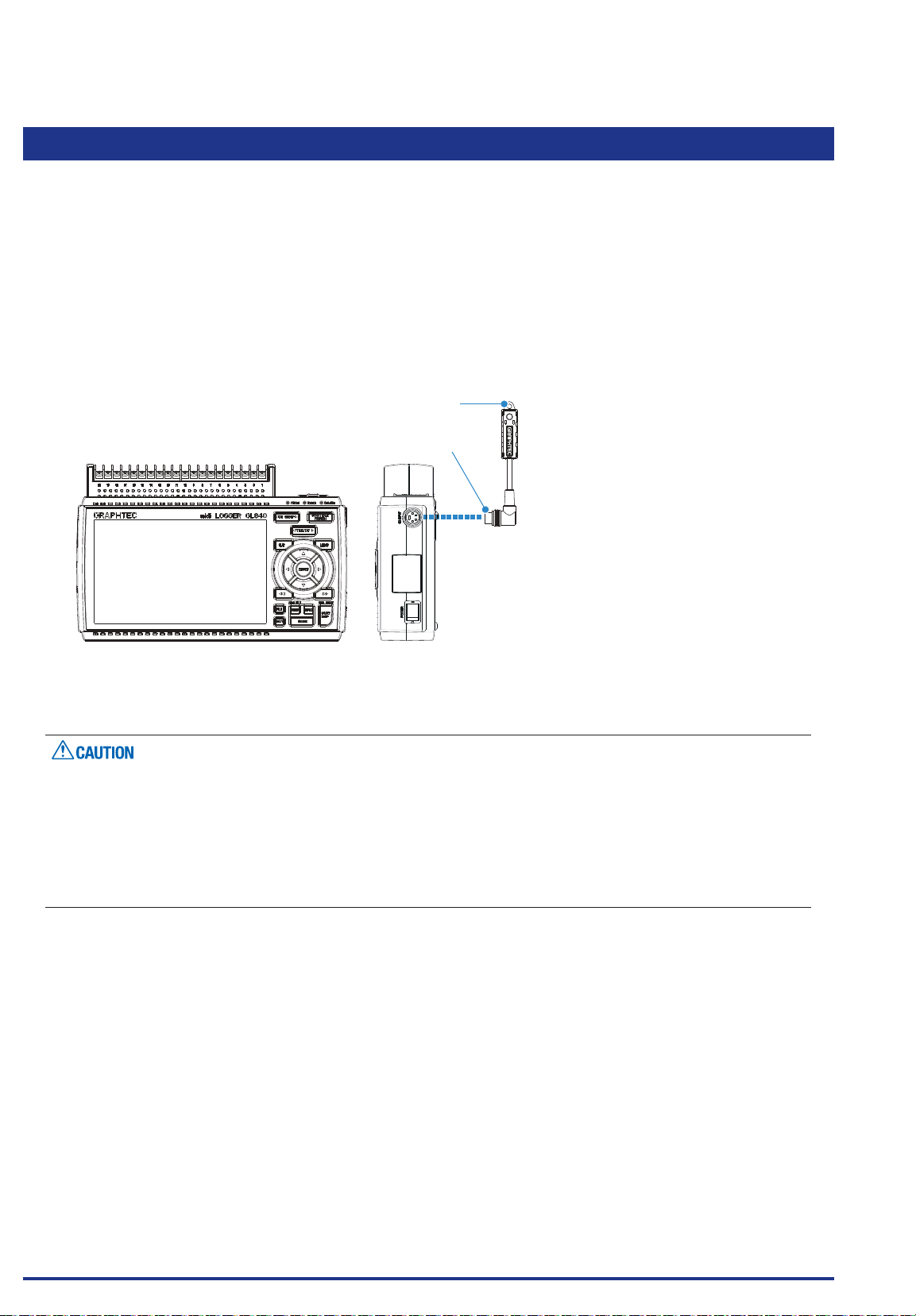
CHAPTER 2 Checks and Preparation
2.16
For the specications of the temperature and humidity sensor, refer to the Instruction Manual supplied in the
sensor.
The connecting procedure between the GL840 and temperature and humidity sensor is described.
• Turn Off the GL840’s power.
• Connect rmly the temperature and humidity sensor’s connector to the GL840's GS sensor and terminal /
• Turn On the GL840’s power and make sure that the sensor settings are displayed on the AMP Setting
Connecting the Temperature and Humidity Sensor (GS-TH) (Optional)
adapter connection terminal (GS-INPUT).
screen.
1. Hook portion
2. Connector
GL840 main module
1. Hook portion ...................Used to mount to a wall.
2. Connector .......................Used to connect to the connector on the GL840 module.
Please do not use in a state in which only the temperature and humidity sensor is attached on a wall or the
•
like.
The damage of the connected cable and connector or the drop of the GL840 may be caused.
The temperature sensor measures the change in capacitance of the conductivity caused by moisture
•
absorption. Therefore, dust, fumes and other organic compound may affect measurements. Usage in
an environment with a large quantity of these substances oating about will cause large measurement
deviations.
Find Quality Products Online at: [email protected]
www.GlobalTestSupply.com
2-33
Page 53
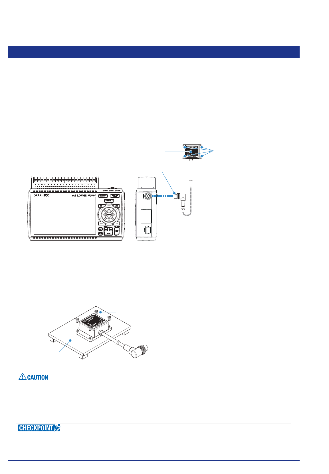
CHAPTER 2 Checks and Preparation
2.17
For the specications of the 3-axis acceleration / temperature sensor, refer to the Instruction Manual
supplied in the sensor.
The connecting procedure between the GL840 and temperature sensor is described.
• Turn Off the GL840’s power.
• Connect rmly the 3-axis acceleration / temperature sensor’s connector to the GL840's GS sensor and
• Turn On the GL840’s power and make sure that the sensor settings are displayed on the AMP Setting
Connecting the 3-axis Acceleration / Temperature Sensor (GS-3AT) (Optional)
terminal / adapter connection terminal (GS-INPUT).
screen.
1. Sensor unit
3. Connector
2. Sensor mounting hole
GL840 main module
1. Sensor unit .....................The 3-axis acceleration and temperature sensor are built in this unit.
2. Sensor mounting hole ....Used to x the sensor.
3. Connector .......................Used to connect to the connector on the GL840 module.
• Check the operating direction of the sensor unit, and then securely mount it using four M3 screws to what
is to be measured
Fixing screw
Object to be measured
The sensor unit is dustproof and splash-resistant (IP54), but the GL840 does not conform to IP54. Please
•
be careful of the operating environment.
Please take care not to drop or shock the sensor.
•
If the sensor’s mounting is loose, it will give inaccurate readings.
•
< Extension cable >
Find Quality Products Online at: [email protected]
The module can be used approx. 1.5 m away from the GL840 by using an extension cable for GS (GS-EXC).
However, you cannot connect and use multiple extension cables.
2-34
www.GlobalTestSupply.com
Page 54
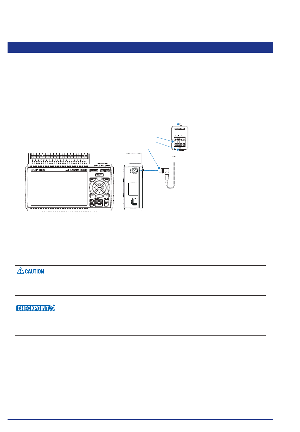
CHAPTER 2 Checks and Preparation
2.18
Connecting the 4ch Voltage / Temperature Terminal (GS-4VT) (Optional)
For the specications of the 4ch voltage / temperature terminal, refer to the Instruction Manual supplied in
the sensor.
The connecting procedure between the GL840 and 4ch voltage / temperature terminal is described.
• Turn Off the GL840’s power.
• Connect rmly the 4ch voltage / temperature terminal’s connector to the GL840's GS sensor and terminal /
adapter connection terminal (GS-INPUT).
• Turn On the GL840’s power and make sure that the sensor settings are displayed on the AMP Setting
screen.
1. Hook portion
2. Input terminal
3. Logic / Pulse input terminal
4. Connector
GL840 main module
1. Hook portion ...................Used to mount to a wall.
2. Input terminal .................Used to connect voltage input or thermocouple.
3.
Logic / Pulse input terminal
..Used to apply logic input.
4. Connector .......................Used to connect to the connector on the GL840 module.
Please do not use in a state in which only the 4ch voltage / temperature terminal is attached on a wall or
the like.
The damage of the connected cable and connector or the drop of the GL840 may be caused.
< Extension cable >
The module can be used approx. 1.5 m away from the GL840 by using an extension cable for GS (GS-EXC).
However, you cannot connect and use multiple extension cables.
Find Quality Products Online at: [email protected]
www.GlobalTestSupply.com
2-35
Page 55
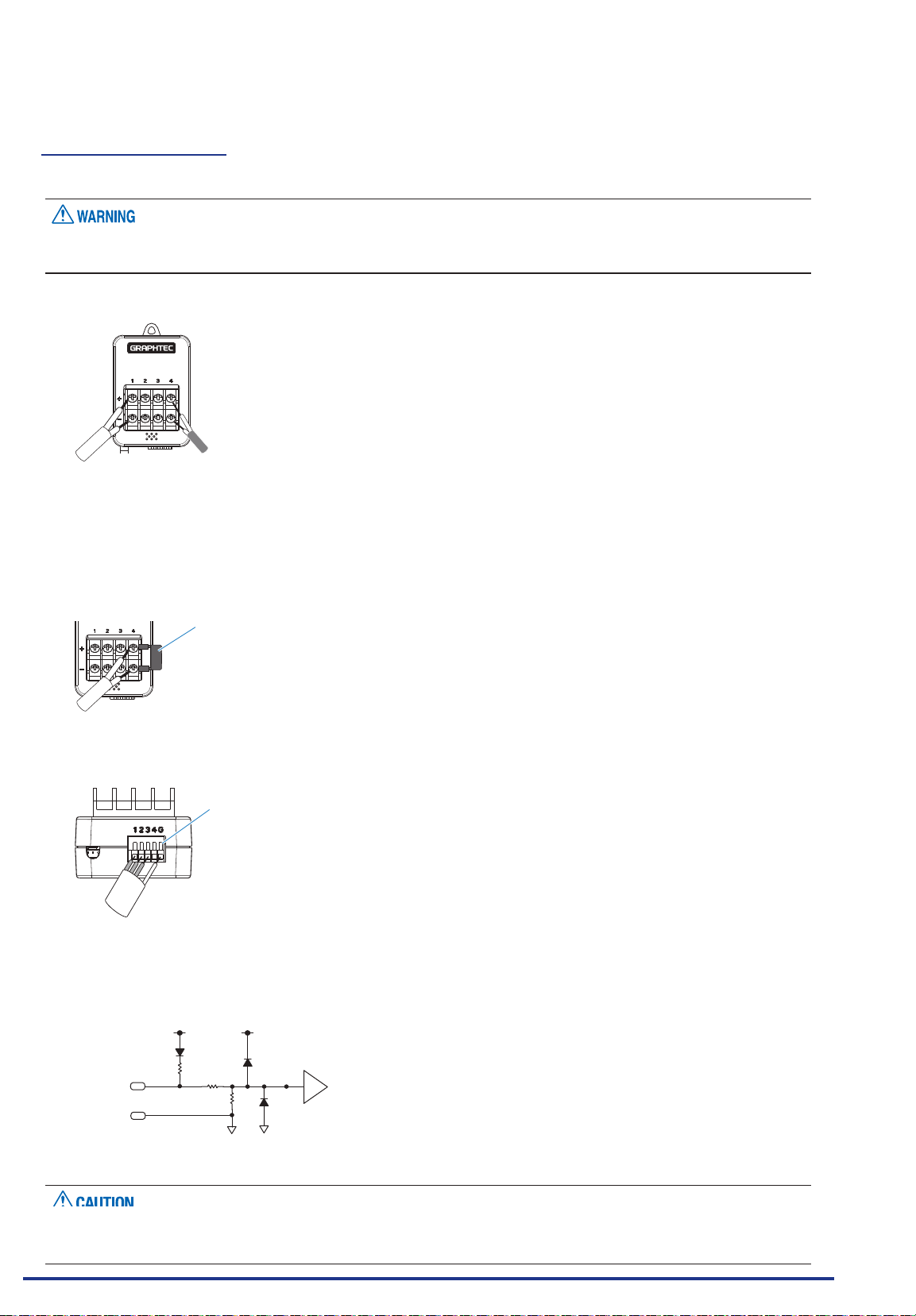
CHAPTER 2 Checks and Preparation
Each input terminal
The connecting procedure of the signal input cable is described.
During wiring, conrm that the signal's supply source is turned OFF to prevent electrical shocks.
Also, position the GL840 input cable away from any power lines and ground cables.
1. Voltage input
Thermocouple
+ .....................................High-voltage terminal (terminal input on the input signal’s high-voltage side)
- ......................................Low-voltage terminal (terminal input on the input signal’s low-voltage side)
2. Thermocouple input
Connect thermocouple to the + and – terminals.
3. Current input
Shunt resistance
E.g.: For 4-20 mA, add 250Ω (±0.1%) resistance and
measure with a 1-5V range.
* For shunt resistance, use the B-551 (option).
Attach shunt resistance when measuring the current input.
4. Logic / pulse input
When inserting the cable, insert it while pressing here.
No. 1 to 4: High-voltage terminal (terminal input on the input signal’s high-voltage side)
G: Low-voltage terminal (terminal input on the input signal’s low-voltage side)
100kΩ
+3.3V
Comparator
180kΩ
+3.3V
10kΩ
LOGIC/PULSE
GND
G is the GND terminal for this GL840.
•
Find Quality Products Online at: [email protected]
For the maximum input voltage, refer to "Regarding Maximum Input Voltage" in the next page.
•
www.GlobalTestSupply.com
2-36
Page 56
CHAPTER 2 Checks and Preparation
Regarding Maximum Input Voltage
To avoid break-downs or short-circuiting accidents, please make sure to abide by the items written below.
In case the input voltage exceeds the specications, the circuit at the input part will break down. Please don't
input it.
< Between input terminal (+)/input terminal (-) >
• Maximum input voltage : DC60Vp-p
< Between input terminal (-)/input terminal (-) >
Maximum input voltage : 60Vp-p
< Between input terminal (-)/GND terminal >
Maximum input voltage : DC60Vp-p
Withstand voltage : 350Vp-p/1 minute
Logic/Pulse
< Between input terminal (+)/GND terminal >
Maximum input voltage : DC24V
Notes on temperature
When measuring the temperature, please pay attention to the following.
Do not block the air vents of the GL840. Leave a clear space of at least 20 cm around it.
•
When rapid temperature change occurs in the input terminals, the error may occur on the measurement.
•
Find Quality Products Online at: [email protected]
www.GlobalTestSupply.com
2-37
Page 57
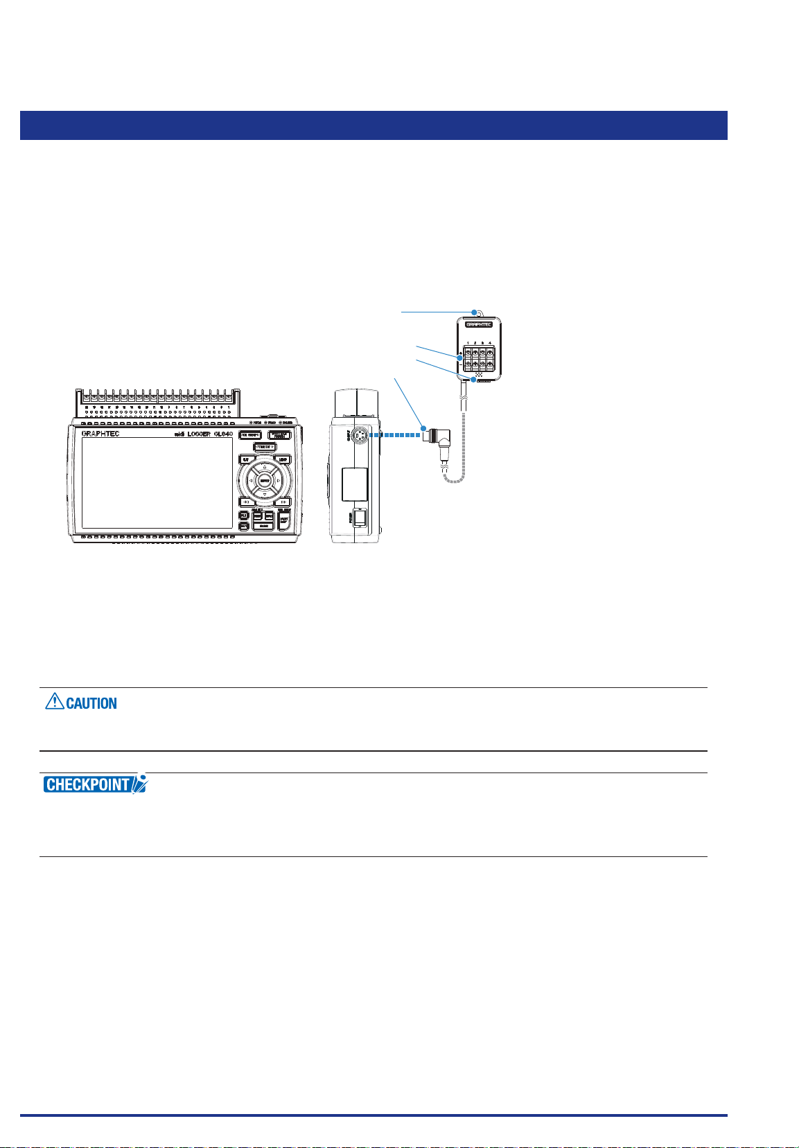
CHAPTER 2 Checks and Preparation
2.19
Connecting the 4ch Thermistor Terminal (GS-4TSR) (Optional)
For the specications of the 4ch thermistor terminal, refer to the Instruction Manual supplied in the sensor.
The connecting procedure between the GL840 and digital sensor is described
• Turn Off the GL840’s power.
• Connect rmly the 4ch thermistor terminal’s connector to the GL840's GS sensor and terminal / adapter
connection terminal (GS-INPUT).
• Turn On the GL840’s power and make sure that the sensor settings are displayed on the AMP Setting
screen.
1. Hook portion
2. Input terminal
3. Logic/Pulse input terminal
4. Connector
GL840 main module
1. Hook portion ...................Used to mount to a wall.
2. Input terminal .................Used to connect Thermistor.
3.
Logic/Pulse input terminal
...Used to input logic / pulse.
4. Connector .......................Used to connect to the connector on the GL840 module.
Please do not use in a state in which only this module is attached on a wall or the like.
The damage of the connected cable and connector or the drop of the GL840 may be caused.
< Extension cable >
The module can be used approx. 1.5 m away from the GL840 by using an extension cable for GS (GS-EXC).
However, you cannot connect and use multiple extension cables.
Find Quality Products Online at: [email protected]
www.GlobalTestSupply.com
2-38
Page 58
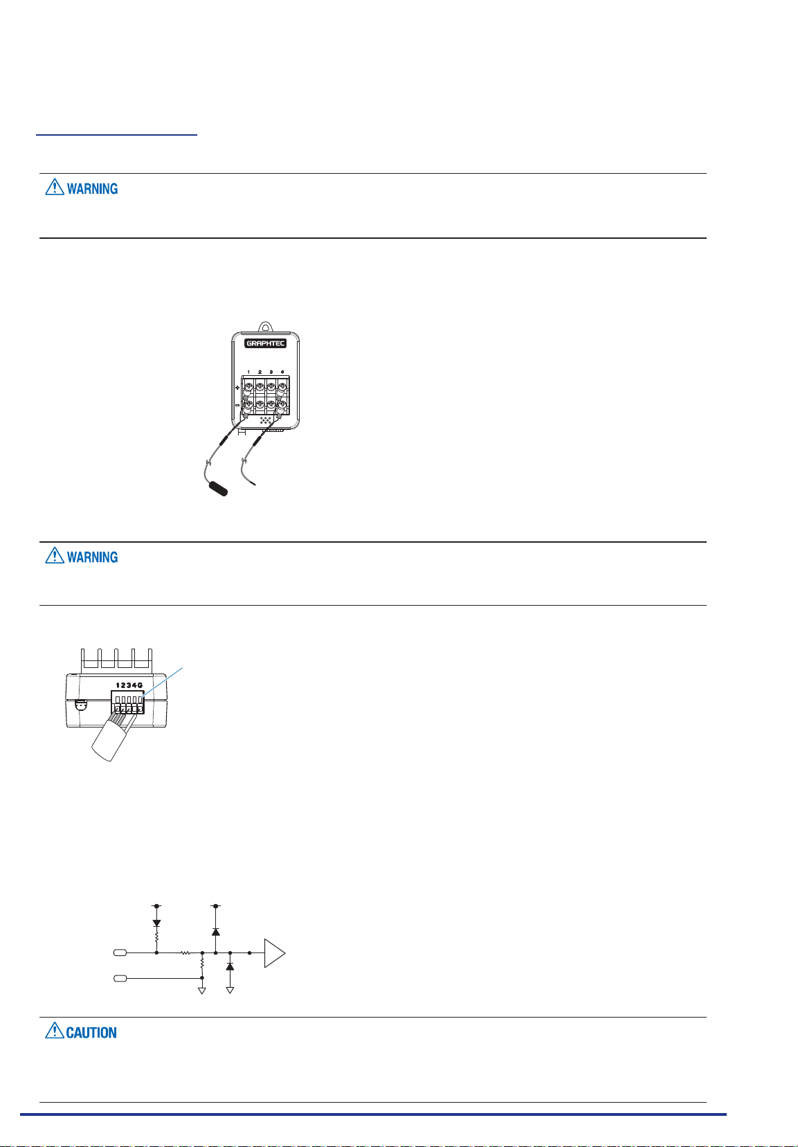
CHAPTER 2 Checks and Preparation
Each input terminal
The connecting procedure of the signal input cable is described.
During wiring, conrm that the signal's supply source is turned OFF to prevent electrical shocks.
Also, position the GL840 input cable away from any power lines and ground cables.
Connect the GS thermistor sensor (GS-103AT-4P (Type A) or GS-103JT-4P (Type J) each sold separately) to
the +/-.
1. Connect the thermistor sensor
Model: GS-103AT-4P
Model: GS-103JT-4P
(Ultra-thin shape)
No. 1 to 4 is the thermistor connection terminal.
These terminals are for thermistor input only. Make sure not to input voltage or electric current, as this can
cause damage.
2. Logic / Pulse input
When inserting the cable, insert it while pressing here.
No. 1 to 4: High potential terminal
(These terminals are used to input the signal of high potential side.)
G: Low potential terminal
(These terminals are used to input the signal of low potential side.)
100kΩ
+3.3V
Comparator
180kΩ
www.GlobalTestSupply.com
+3.3V
10kΩ
LOGIC/PULSE
GND
G is the GND terminal for this module.
•
Please apply the maximum input voltage, referring to "Regarding Maximum Input Voltage" in the next
Find Quality Products Online at: [email protected]
•
page.
2-39
Page 59

CHAPTER 2 Checks and Preparation
Regarding Maximum Input Voltage
To avoid break-downs or short-circuiting accidents, please make sure to abide by the items written below.
In case the input voltage exceeds the specications, the circuit at the input part will break down. Please do
not input it.
Logic / Pulse
<Between input terminal (+)/GND terminal >
Maximum input voltage : DC24V
Find Quality Products Online at: [email protected]
2-40
www.GlobalTestSupply.com
Page 60
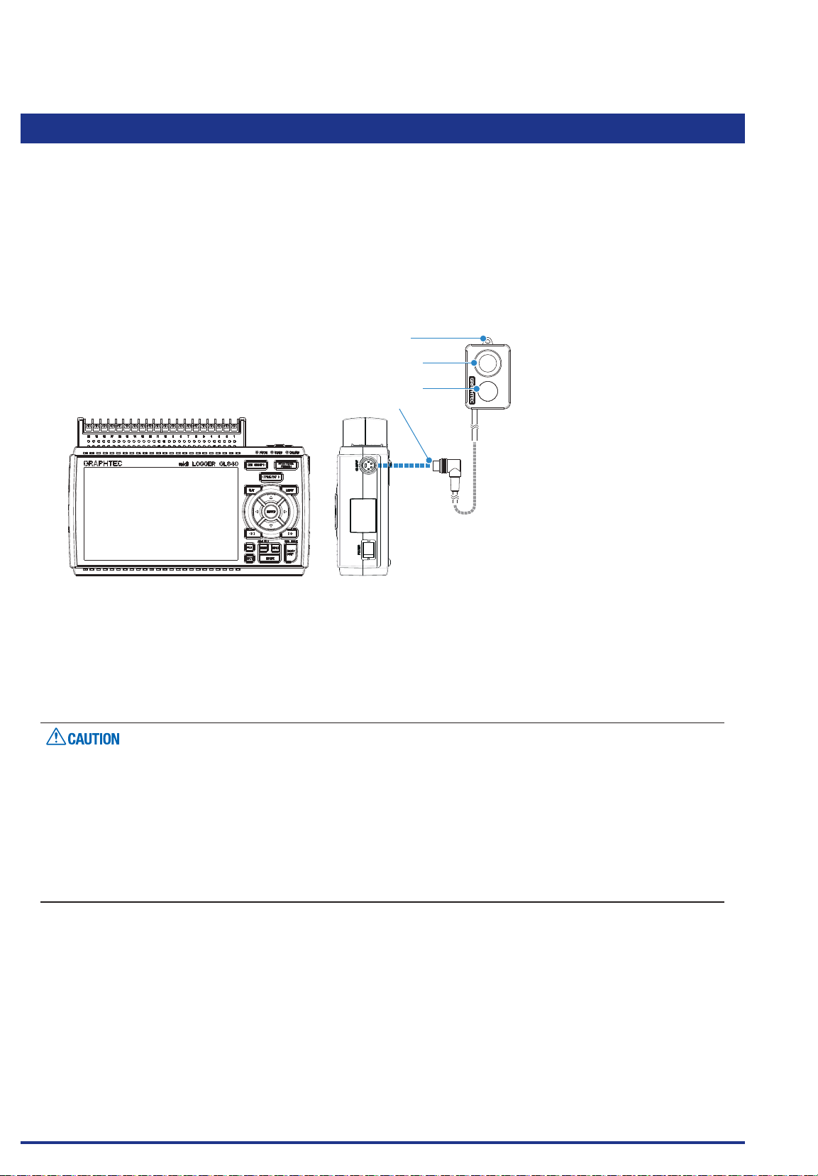
CHAPTER 2 Checks and Preparation
2.20
For the specications of illumination / ultraviolet sensor, refer to the Instruction Manual supplied in the
sensor.
The connecting procedure between the GL840 and illumination / ultraviolet sensor is described.
• Turn Off the GL840’s power.
• Connect rmly the illumination / ultraviolet sensor’s connector to the GL840's GS sensor and terminal /
• Turn On the GL840’s power and make sure that the sensor settings are displayed on the AMP Setting
Connecting the Illumination / Ultraviolet Sensor (GS-LXUV) (Optional)
adapter connection terminal (GS-INPUT).
screen.
1. Hook portion
2. Illumination sensor
3. Ultraviolet sensor
4. Connector
GL840 main module
1. Hook portion ...................Used to mount to a wall.
2. Illumination sensor .........Sensor unit that measures illumination rays.
3. Ultraviolet sensor ...........Sensor unit that measures ultraviolet rays.
4. Connector .......................Used to connect to the connector on the GL840 module.
Please do not use in a state in which only the illumination / ultraviolet sensor is attached on a wall or the
•
like.
The damage of the connected cable and connector or the drop of the GL840 may be caused.
When measuring ultraviolet rays that have an effect on the eyes or the skin, wear protective glasses, apply
•
light shielding, etc.
If the sensor unit becomes dirty, this may affect measurements. Wipe it down with a soft cloth.
•
Make sure to handle the sensor unit in a way that it will not crack. If the sensor unit is cracked it may affect
•
measurements. Replace the sensor if cracked.
Find Quality Products Online at: [email protected]
www.GlobalTestSupply.com
2-41
Page 61
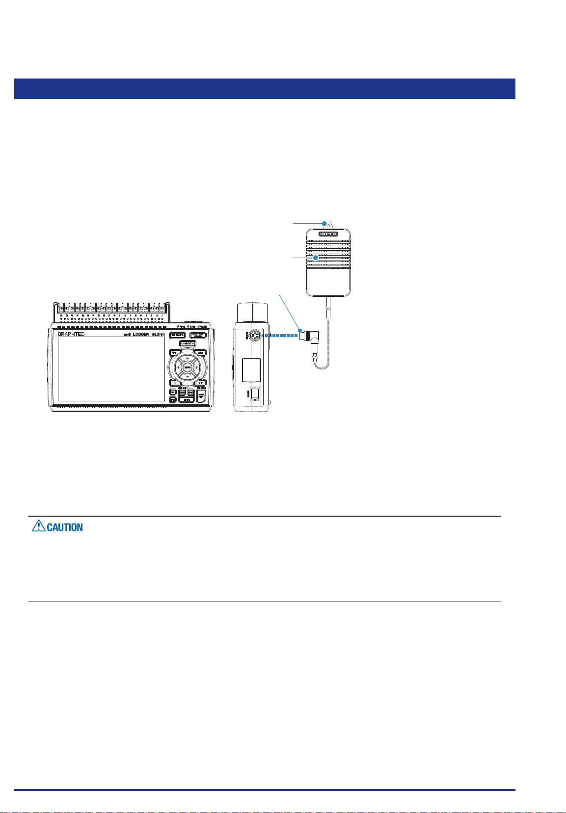
CHAPTER 2 Checks and Preparation
2.21 Connecting the CO2 Sensor (GS-CO2) (Optional)
For the specications of CO2 sensor, refer to the Instruction Manual supplied in the sensor.
The connecting procedure between the GL840 and CO2 sensor is described.
• Turn Off the GL840’s power.
• Connect rmly the CO2 sensor’s connector to the GL840's GS sensor and terminal / adapter connection
terminal (GS-INPUT).
• Turn On the GL840’s power and make sure that the sensor settings are displayed on the AMP Setting
screen.
1. Hook portion
2. Internal sensor
3. Connector
GL840 main module
1. Hook portion ...................Used to mount to a wall.
2. Internal sensor .................A sensor that detects the CO2 is built in.
The lamp for detecting ashes every two seconds.
3. Connector .......................Used to connect to the connector on the GL840 main module.
Please do not use in a state in which only the CO2 sensor is attached on a wall or the like.
•
The damage of the connected cable and connector or the drop of the GL840 may be caused.
Do not use the module close to your face.
•
Your breath may affect measurements.
Blocking the module’s ventilation hole may cause the airow to affect measurements.
•
Find Quality Products Online at: [email protected]
2-42
www.GlobalTestSupply.com
Page 62
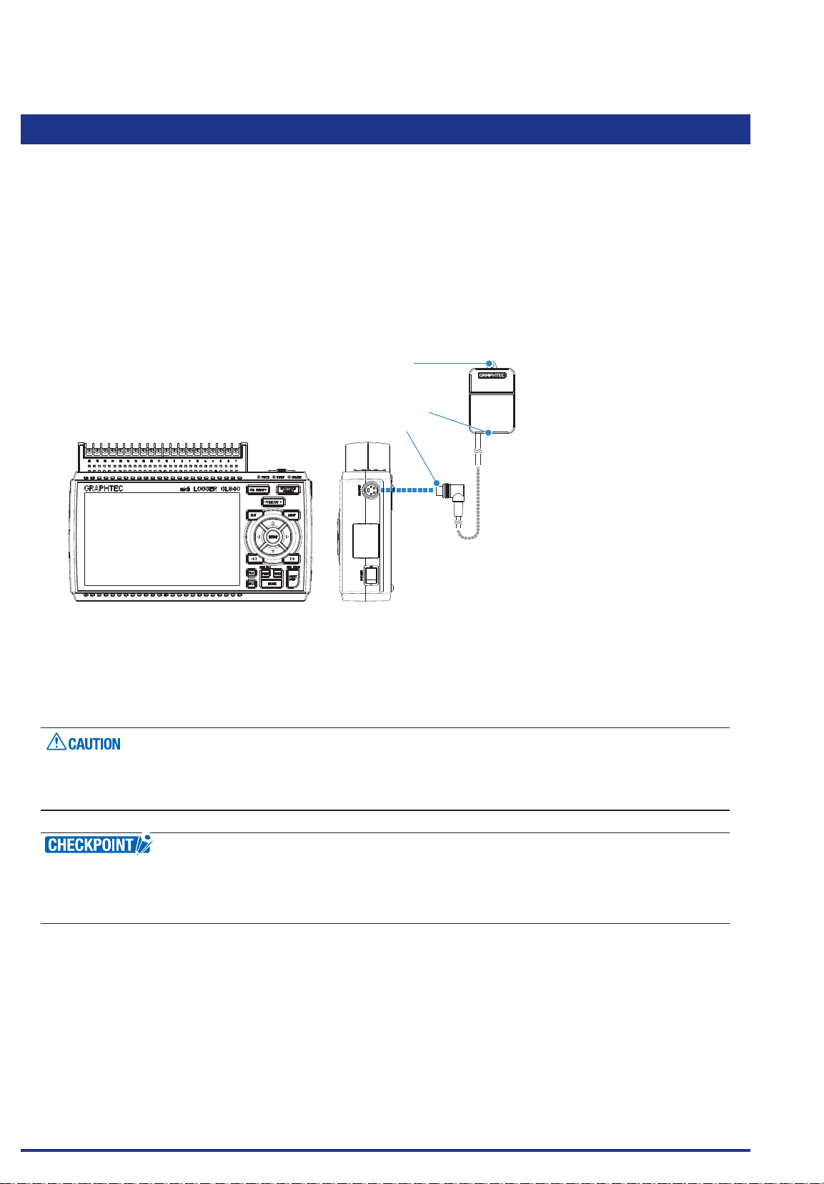
CHAPTER 2 Checks and Preparation
2.22
Connecting the Adapter for AC Current Sensor (GS-DPA-AC) (Optional)
For the connecting procedure and specications of Adapter for AC current sensor, refer to the Instruction
Manual supplied in the sensor.
The connecting procedure between the GL840 and Adapter for AC current sensor is described.
• Turn Off the GL840’s power.
• Connect rmly the connector of Adapter for the AC current sensor to the GL840's GS sensor and terminal
/ adapter connection terminal (GS-INPUT).
• Turn On the GL840’s power and make sure that the sensor settings are displayed on the AMP Setting
screen.
1. Hook portion
2. Input terminal
3. Connector
GL840 main module
1. Hook portion ...................Used to mount to a wall.
2. Input terminal .................Used to connect to the AC current sensor (sold separately).
3. Connector .......................Used to connect to the connector on the GL840 module.
Please do not use in a state in which only the Adapter for AC current sensor is attached on a wall or the
like.
The damage of the connected cable and connector or the drop of the GL840 may be caused.
< Extension cable >
The module can be used approx. 1.5 m away from the GL840 by using an extension cable for GS (GS-EXC).
However, you cannot connect and use multiple extension cables.
Find Quality Products Online at: [email protected]
www.GlobalTestSupply.com
2-43
Page 63
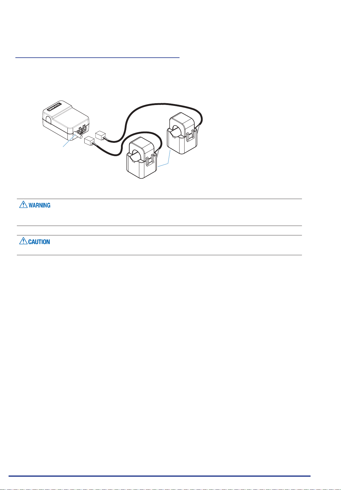
CHAPTER 2 Checks and Preparation
Connecting procedure of the AC current sensor
1. Connect the AC current sensor (GS-AC**A, sold separately) to the module.
Connecting : Insert the connector in until it locks in.
Disconnecting : Pull the connector out while pressing down on the lock portion on the bottom with your
nger.
Connector cable
K=>L
The connector is available exclusively to be used to connect the AC Current Sensor. Do not connect it to
voltages, other electrical currents, etc. It will damage the module.
Pulling the AC Current Sensor’s cable and holding the sensor by the cable will damage the cable’s wires.
K=>L
AC Current Sensor
Find Quality Products Online at: [email protected]
www.GlobalTestSupply.com
2-44
Page 64
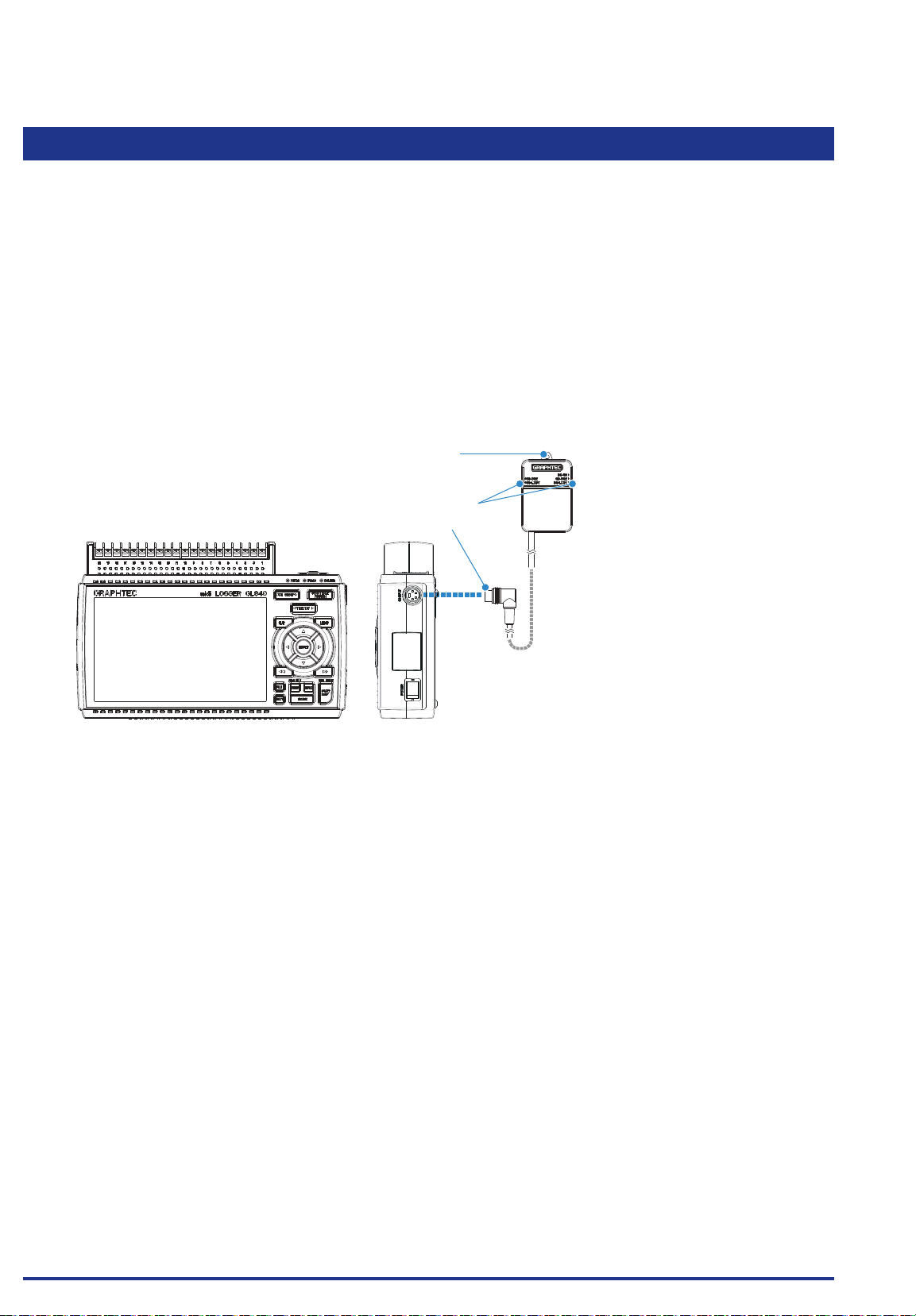
CHAPTER 2 Checks and Preparation
2.23 Connecting the Branch Adapter for GS (GS-DPA) (Optional)
For the specications of branch adapter for GS, refer to the Instruction Manual supplied in the sensor.
There are three ways to connect with a combination of the GL840 and various sensors. Please check the
information of the sensor and perform the connection using the following steps.
• Turn Off the GL840’s power.
• Be sure to connect two types of digital sensors to the Branch Adapter for GS.
• Connect rmly the branch adapter for GS to the GL840 sensor connection terminal (GS-INPUT).
* After connecting the branch adapter for GS to the GL840, the digital sensor is not recognized even if the
digital sensor is connected.
• Turn On the GL840’s power and make sure that the sensor settings are displayed on the AMP Setting
screen.
1. Hook portion
2. Sensor connector
3. Connector
GL840 main module
1. Hook portion ...................Used to mount to a wall.
2. Sensor connector ...........Used to connect to the AC current sensor (sold separately).
3. Connector .......................Used to connect to the connector on the GL840 module.
Find Quality Products Online at: [email protected]
www.GlobalTestSupply.com
2-45
Page 65
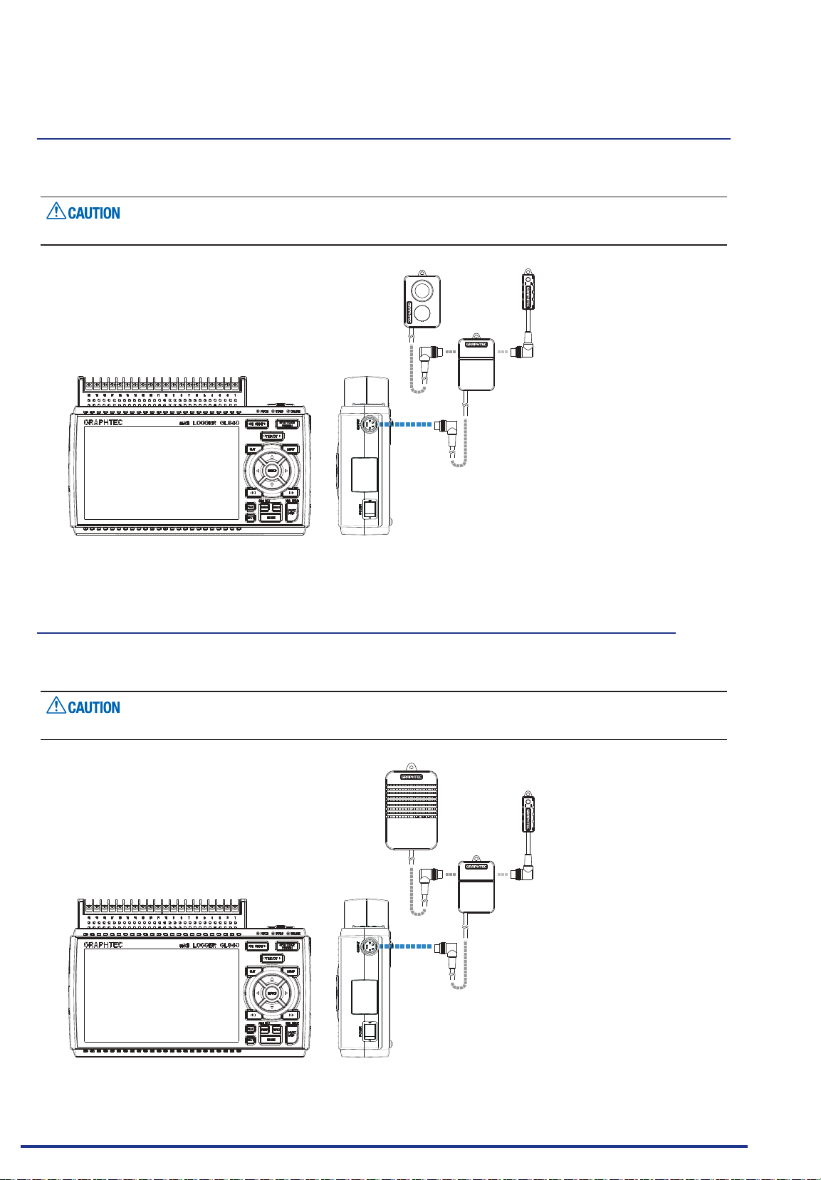
CHAPTER 2 Checks and Preparation
1.
Combined illumination / ultraviolet sensor and temperature and humidity sensor measurement
Composite measurement can be done by using the illumination / ultraviolet sensor (GS-LXUV) and the
temperature and humidity sensor (GS-TH) (each sold separately).
It is not possible to be used by connecting two same sensors.
Illumination / Ultraviolet sensor
(GS-LXUV)
Branch adapter for GS
(GS-DPA)
GL840 main module
Temperature and Humidity sensor
(GS-TH)
2. Combined CO2 sensor and temperature and humidity sensor measurement
Composite measurement can be done by using the CO2 sensor (GS-CO2) and the temperature and
humidity sensor (GS-TH) (each sold separately).
It is not possible to be used by connecting two same sensors.
CO2 Sensor
(GS-CO2)
Branch adapter for GS
(GS-DPA)
GL840 main module
Find Quality Products Online at: [email protected]
www.GlobalTestSupply.com
Temperature and Humidity sensor
(GS-TH)
2-46
Page 66

CHAPTER 2 Checks and Preparation
3. Combined CO2 sensor and illumination / ultraviolet sensor
Composite measurement can be done by using the CO2 sensor (GS-CO2) and the illumination / ultraviolet
sensor (GS-LXUV) (each sold separately).
It is not possible to be used by connecting two same sensors.
CO2 Sensor
(GS-CO2)
GL840 main module
Illumination / Ultraviolet sensor
(GS-LXUV)
Branch adapter for GS
(GS-DPA)
Find Quality Products Online at: [email protected]
www.GlobalTestSupply.com
2-47
Page 67
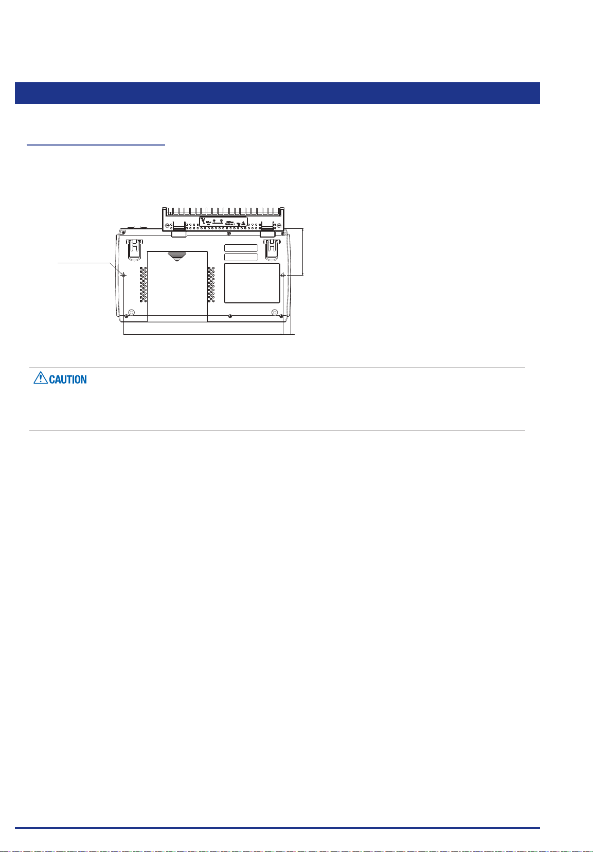
CHAPTER 2 Checks and Preparation
218 11
2.24 When Fixing the GL840 Body
Fixing the GL840 body
When xing the GL840 body to prevent the dropout of the GL840, the two nuts on the back must be used.
* Recommended tightening torque: 14kgf/cm
When xing the GL840, it must be installed in horizontal state rather than in vertical or inclined state.
2-M4 L5 Nut
To prevent possible malfunction, do not block the air vents of the GL840.
If the GL840 is installed in other than the state described above, the measurement accuracy may not meet
the specications.
64
Find Quality Products Online at: [email protected]
2-48
www.GlobalTestSupply.com
Page 68
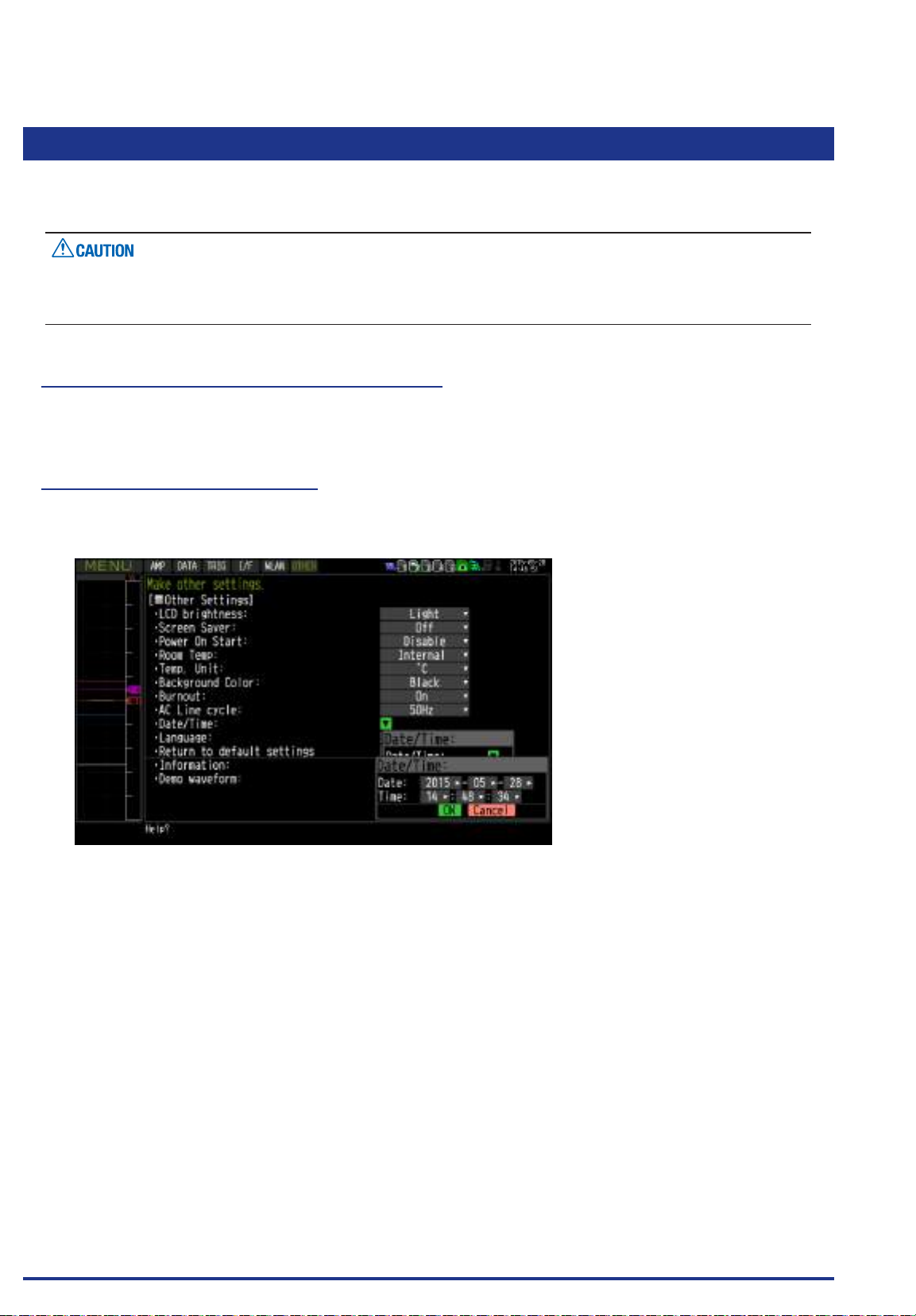
CHAPTER 2 Checks and Preparation
2.25 Setting the Date and Time
If you are using the GL840 for the rst time, charge the internal rechargeable battery and then make the date
and time settings.
If the GL840 is not used for a period of approximately six months, the internal rechargeable battery may
be discharged and the date and time may revert to the initial settings. If this happens, recharge the battery
before using the GL840.
How to Recharge the Rechargeable Battery
Using the AC adapter provided, connect the GL840 to a mains power outlet, turn on the power switch, and
then leave the GL840 connected for at least 24 hours.
How to Set the Date and Time
Press the [MENU] key, display the “OTHER” screen, and then set the date and time at the Date/Time
Settings sub-menu. For details, refer to “Date/Time” in “3.4 Setting Menus”.
Find Quality Products Online at: [email protected]
www.GlobalTestSupply.com
2-49
Page 69

CHAPTER 3 Settings and Measurement
CHA PT ER 3 Setting s a n d Measu r ement
This chapter describes the setting and measurement procedures for the GL840.
PRODUCT SUMMARY
3.1 Window names and functions
3.2 Key Operation
3.3 Operation Modes
3.4 Setting Menus
3.5 WEB Server Function
3.6 List of Error Codes
Find Quality Products Online at: [email protected]
www.GlobalTestSupply.com
3-1
Page 70
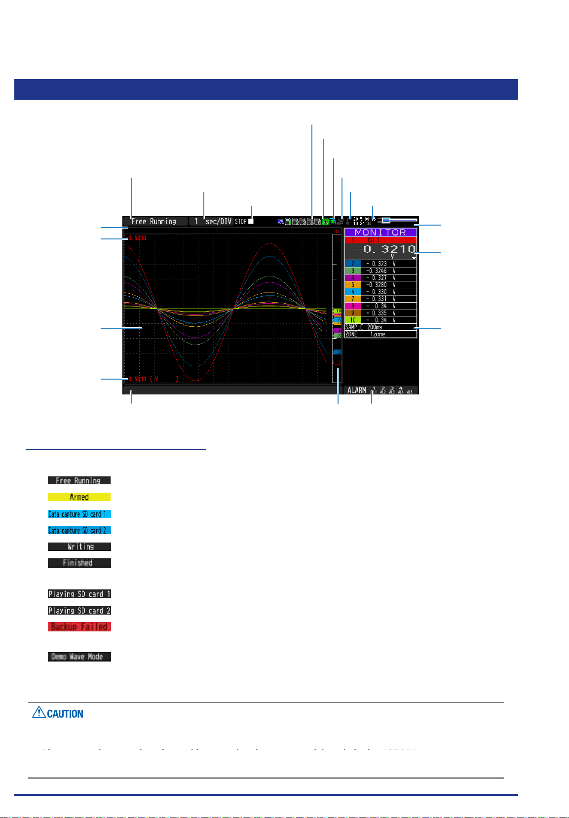
CHAPTER 3 Settings and Measurement
3.1 Window names and functions
1. Status message display area
2. Time/DIV display area
3. Status mark
4. Wireless sensor display
5. Device access display
(Internal memory)
6. Device access display
(SD memory card 2 / wireless LAN display)
7. Remote lamp
8. Key lock display
9. Clock display
19. Data capture bar
18. Scale upper limit
17. Waveform display area
16. Scale lower limit
13. Alarm display area14. Pen display15. File name display area
10. AC/Battery status indicator
11. Digital display area
12. Quick settings
1. Status message display area
Displays the operation status of the GL840.
: Appears in the start up status or when data is not being captured.
: Appears while waiting for trigger generation after measurement is started.
* : Displayed when the data is captured to the internal memory (SD1).
* : Displayed when the data is captured to the SD memory card (SD2).
* : Displayed when performing the capturing stop process.
: Appears when the GL840 waits for you to press the [Start/Stop] key to stop it after
data capture.
* : Displayed when the data in the internal memory (SD1) is replayed.
* : Displayed when the data in the SD memory card (SD2) is replayed.
: Appears when backup fails (e.g. when the SD memory card specied as the backup
destination has been removed).
: Appears when a demo waveform is being displayed, not measurement data.
*
Refer to "(3) TRIG settings" in "3.4 Setting Menus" for details on the data capture such as a trigger and repeat.
* Refer to “(2) capture destination le name” in “3.4 Setting Nemus” for details on data capture setting.
Please do not turn off the power when the status message of “Capturing to SD memory card 1 (2)” or
“Writing” is displayed (“ * ” status icon). The data is damaged, and it will not be captured.
Please start the operation after making sure that the status mark is switched to "STOP".
Find Quality Products Online at: [email protected]
The internal memory is displayed as the SD1 or SD CARD1.
www.GlobalTestSupply.com
3-2
Page 71
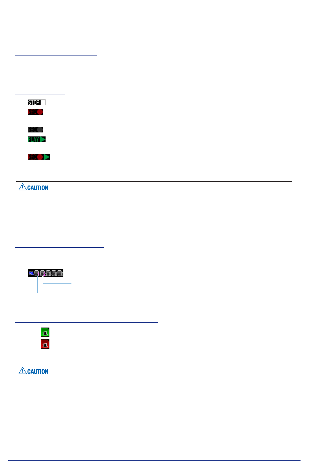
CHAPTER 3 Settings and Measurement
2. Time/DIV display area
Displays the current time scale.
3. Status mark
: Appears when neither capture nor replay is in progress.
: Displayed when saving the captured data in the internal memory (SD1) or SD
memory card (SD2).
: Appears when waiting for a trigger during capturing and the stop key after capturing.
: Displayed when replaying the captured data in the internal memory (SD1) or SD
memory card (SD2).
: Displayed when replaying the captured data in the internal memory (SD1) or SD
memory card (SD2) during data capture or replaying it the data in two-screen (Refer
to “(10) REVIEW” in “3.2 Key Operation”.).
Please do not turn Off the power and do not remove the SD memory card when the status icon indicates
other than “STOP”. The data is damaged, and it will not be accessed.
Please start the operation after making sure that the status mark is switched to "STOP".
4. Wireless sensor display
Displayed when the GL840 is connected to the GL100-WL (GS sensor and terminal/addapter connection)
through wireless connection.
: The wireless sensor setting is disabled (Off).
: The wireless sensor setting is enabled (On), but the device is not searched.
: Wireless sensor is registered and recognized.
5. Device access display (Internal memory)
: Not accessed to the internal memory (SD1).
: Accessed to the internal memory (SD1).
During accessing to the internal memory (SD1), the POWER LED blinks.
Please do not turn Off the GL840’s power when accessing the internal memory (SD1). The data is damaged,
and it will not be accessed.
Find Quality Products Online at: [email protected]
www.GlobalTestSupply.com
3-3
Page 72
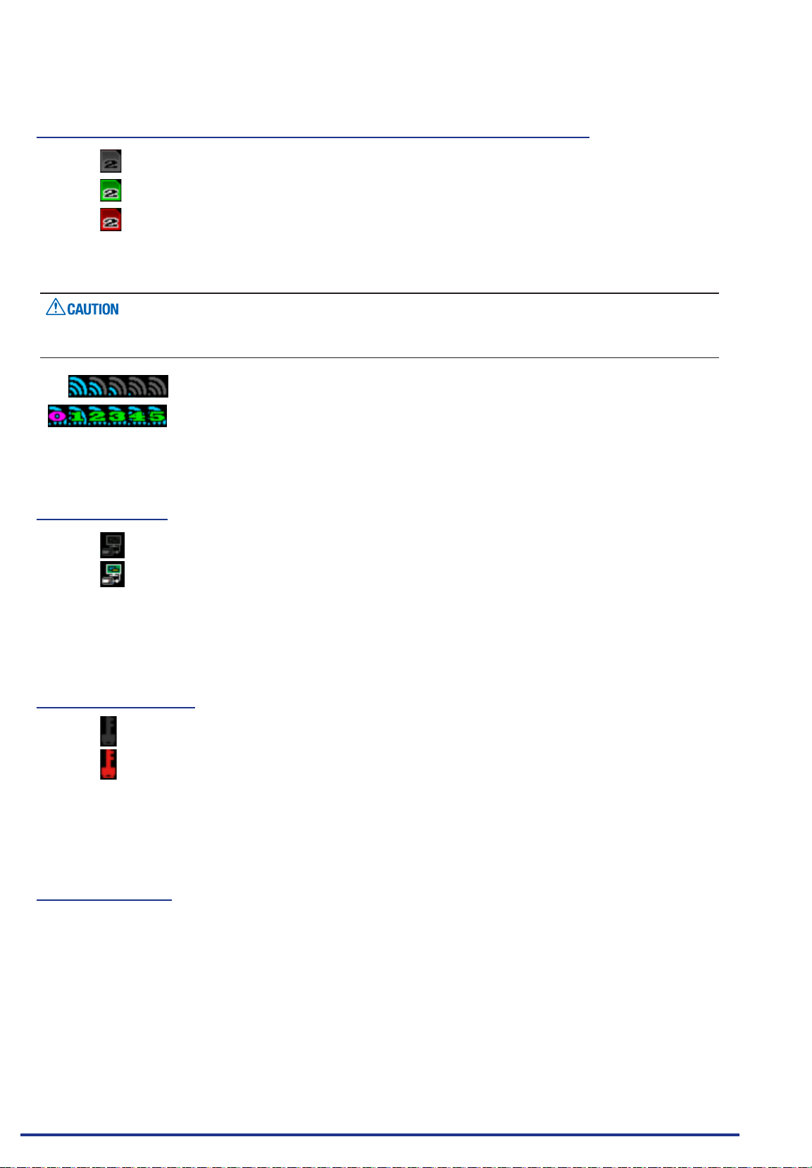
CHAPTER 3 Settings and Measurement
6. Device access display (SD memory card 2 / wireless LAN display)
: The SD memory card is not inserted into the SD CARD (SD2) slot.
: The SD memory card is inserted into the SD CARD (SD2) slot, but it is not accessed.
: The SD memory card in the SD CARD (SD2) slot is accessed. Do not remove the SD
memory card.
During accessing to the SD memory card, the POWER LED blinks.
Please do not remove the SD memory card and do not turn Off the GL840’s power when accessing the SD
memory card. The data is damaged, and it will not be accessed.
: The radio eld intensity display of base unit (5 stages from Strong to Weak).
: The number of child units which are connecting to the GL840 is displayed when
setting to base unit.
7. Remote lamp
: Indicates local mode. Operations can be conducted on the GL840.
: Indicates remote mode. With some exceptions, operations must be conducted on a PC.
When you cancel the connection on the application (GL100_240_840APS), the GL840 is
automatically sent back to local mode. If local mode is not entered, press the [QUIT] key.
8. Key lock display
: Not in key lock status. Normal operations are enabled.
: Key lock status. All the keys are locked.
Refer to “(14) To cancel key lock by password” in “3.4 Setting Menus” for details on the key
lock.
9. Clock display
Displays the current date and time.
Refer to “(6) OTHER settings” in “3.4 Setting Menus” for details on date and time settings.
Find Quality Products Online at: [email protected]
3-4
www.GlobalTestSupply.com
Page 73
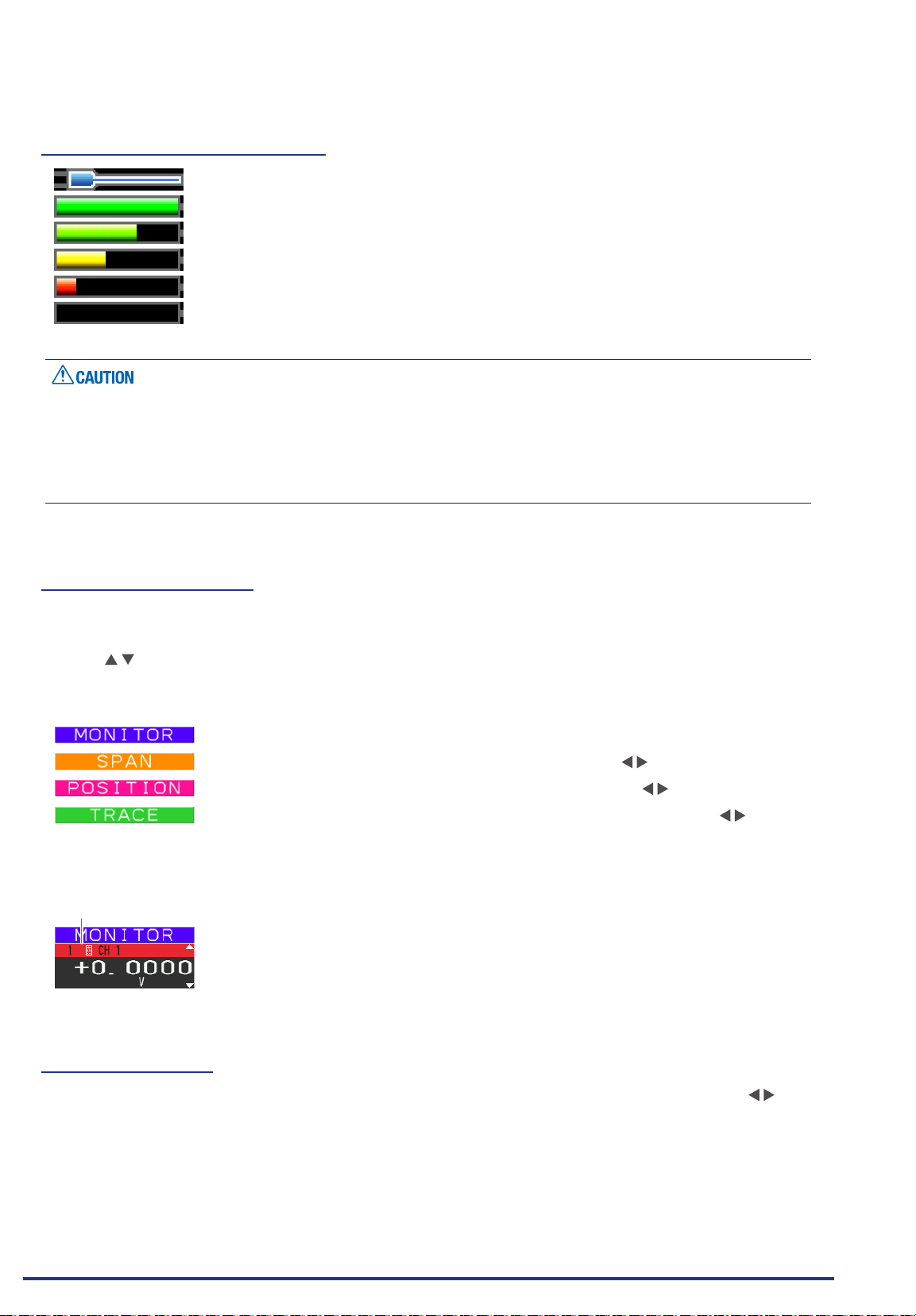
CHAPTER 3 Settings and Measurement
10. AC/battery status indicator
: Running on AC or DC power supply.
: Running on the battery. The remaining battery power is 100 to 91%.
: Running on the battery. The remaining battery power is 90 to 61%.
: Running on the battery. The remaining battery power is 60 to 31%.
: Running on the battery. The remaining battery power is 30 to 11%.
: Running on the battery. The remaining battery power is 10% or below.
Data capture automatically stops when the remaining battery power drops to 10% or below during data
•
capture.
The power is automatically turned off when the remaining battery power is 0%.
•
Please use the remaining battery display as a guide.
•
This indicator does not guarantee the operating time with battery.
11. Digital display area
Displays the input value of each channel and span. Use the [SPAN/TRACE/POSITION] keys to switch the
display.
Use the key to select the channel you want to activate (enlarged display).
The waveform of the active channel is displayed at the top.
: Displays the input value.
: The span of the active channel can be changed using the keys.
: The position of the active channel can be changed using the keys.
: The ON or OFF of the active channel display can be changed using the keys.
Refer to “(2) SPAN/TRACE/POSITION” in “3.2 Key Operation” for details.
As described below, the CH indicating the calculation mark is the channel which calculation between the
CHs is enabled (On).
Calculation mark
12. Quick settings
The settings of the sampling interval and the division of waveform display can be changed. Use the keys
to activate the Quick setting and the left/right keys to change values.
For details, refer to “(12) Quick setting” in “3.4 Setting Menus”.
* The "SAMPLE" item cannot be changed during data capture.
Find Quality Products Online at: [email protected]
www.GlobalTestSupply.com
3-5
Page 74
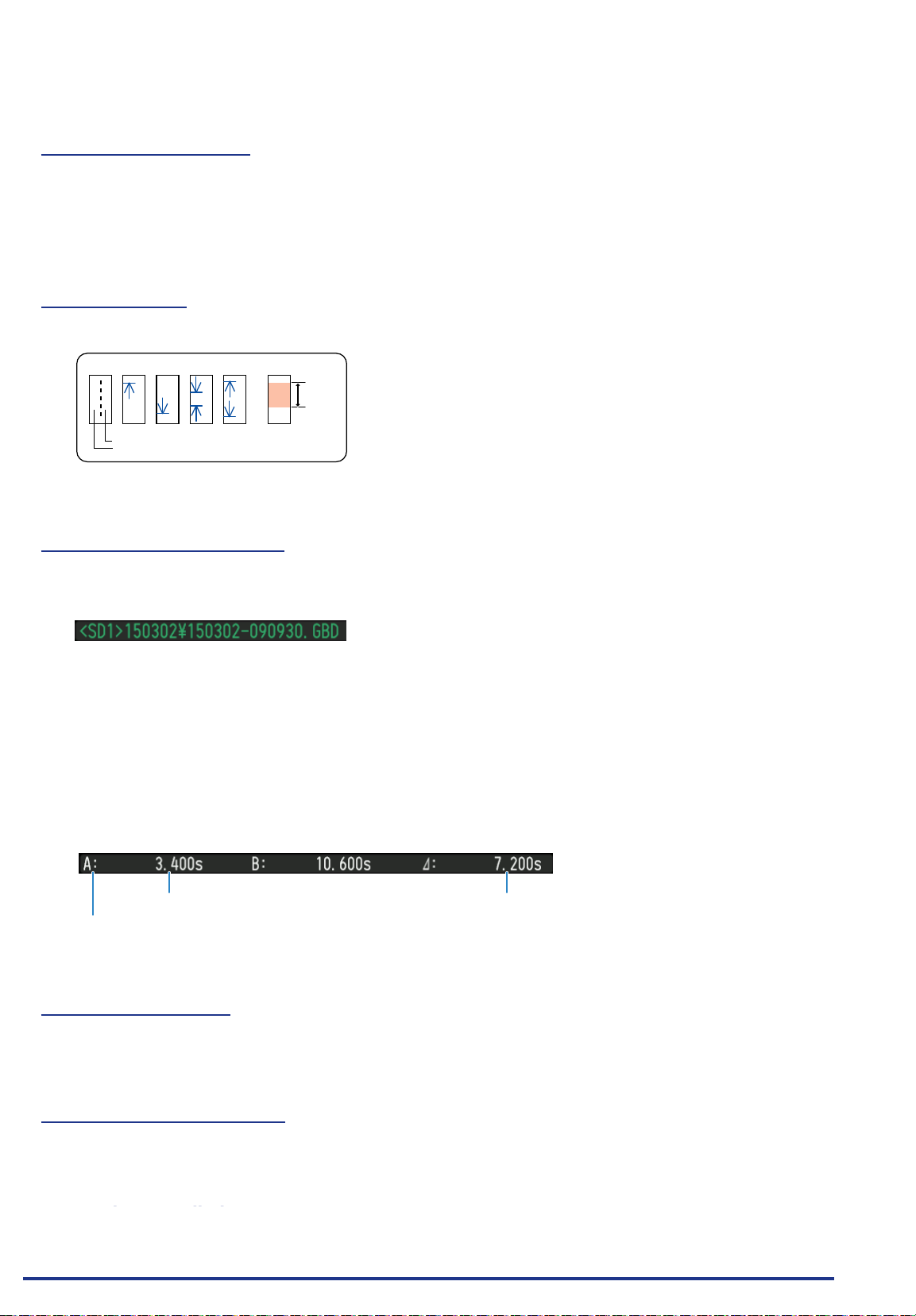
CHAPTER 3 Settings and Measurement
13. Alarm display area
Displays the alarm output terminal status.
The number with which an alarm has occurred is displayed in red. The channel with the alarm cause has a
red input value in the digital display area.
14. Pen display
Displays the each channel signal position, trigger position, and alarm range.
Trigger position Alarm range
Rising Falling Win In Win Out
Stop position
Start position
15. File name display area
(1) During data capture
A capture le name is displayed during capture.
* If the ring recording setting is ON, a le name displayed during capture ends with "_RINGx" (x
represents a number) but the actual le name does not include "_RINGx".
In the above gure, if the ring recording is set to ON, the le name during capture will be displayed,
for example, as "<SD1>150302\150302-090930_RING4.GBD" but the actually created le will be
"<SD1>150302\150305-090930_.GBD".
* Refer to “(2) DATA settings” in “3.4 Setting Menus” for details.
(2) During data replay
Information on the time axis of the cursor is displayed during replay.
Time to which the cursor points
Selected cursor
Time difference between Cursors A and B
16. Scale lower limit
Displays the scale lower limit of the currently active channel.
17. Waveform display area
Displays the waveform of the input signal.
18. Scale upper limit
Find Quality Products Online at: [email protected]
Displays the scale upper limit of the currently active channel.
3-6
www.GlobalTestSupply.com
Page 75
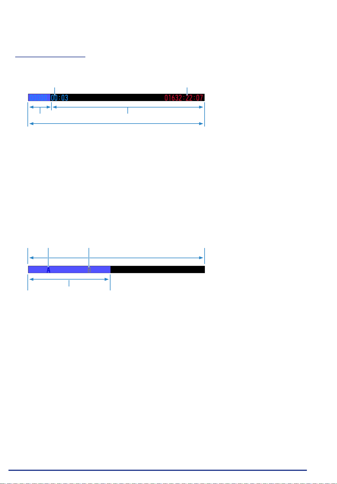
CHAPTER 3 Settings and Measurement
19. Data capture bar
(1) During data capture
Displays the elapsed time and the internal memory and SD memory card usage status.
Elapsed time Remaining time for data capture
Amount of internal memory and
SD memory card used
Total amount of internal memory and SD memory card
Amount of internal memory and SD
memory card used
If, for example, 4 GB SD memory card is inserted and about 100 MB is used before data capture, the
total amount of memory is 4 GB, the amount of SD memory card used is about 100 MB, and the amount
of SD memory card remaining is about 3.9 GB. As time elapses during data capture, the amount of used
SD memory card increases and the amount of remaining memory decreases.
The remaining time for data capture shows a length of time during which data capture is available with the
amount of remaining SD memory card. If the amount of remaining SD memory card is more than 2 GB,
however, this part shows remaining time during which data capture is available with one 2 GB le.
* Remaining time more than 99999 hours is displayed as "++++:++:++".
(2) During data replay
Displays the display position, cursor position, and trigger position graphically.
Cursor A position Cursor B position
Capture data size
Range for which a waveform is currently
displayed
Find Quality Products Online at: [email protected]
www.GlobalTestSupply.com
3-7
Page 76
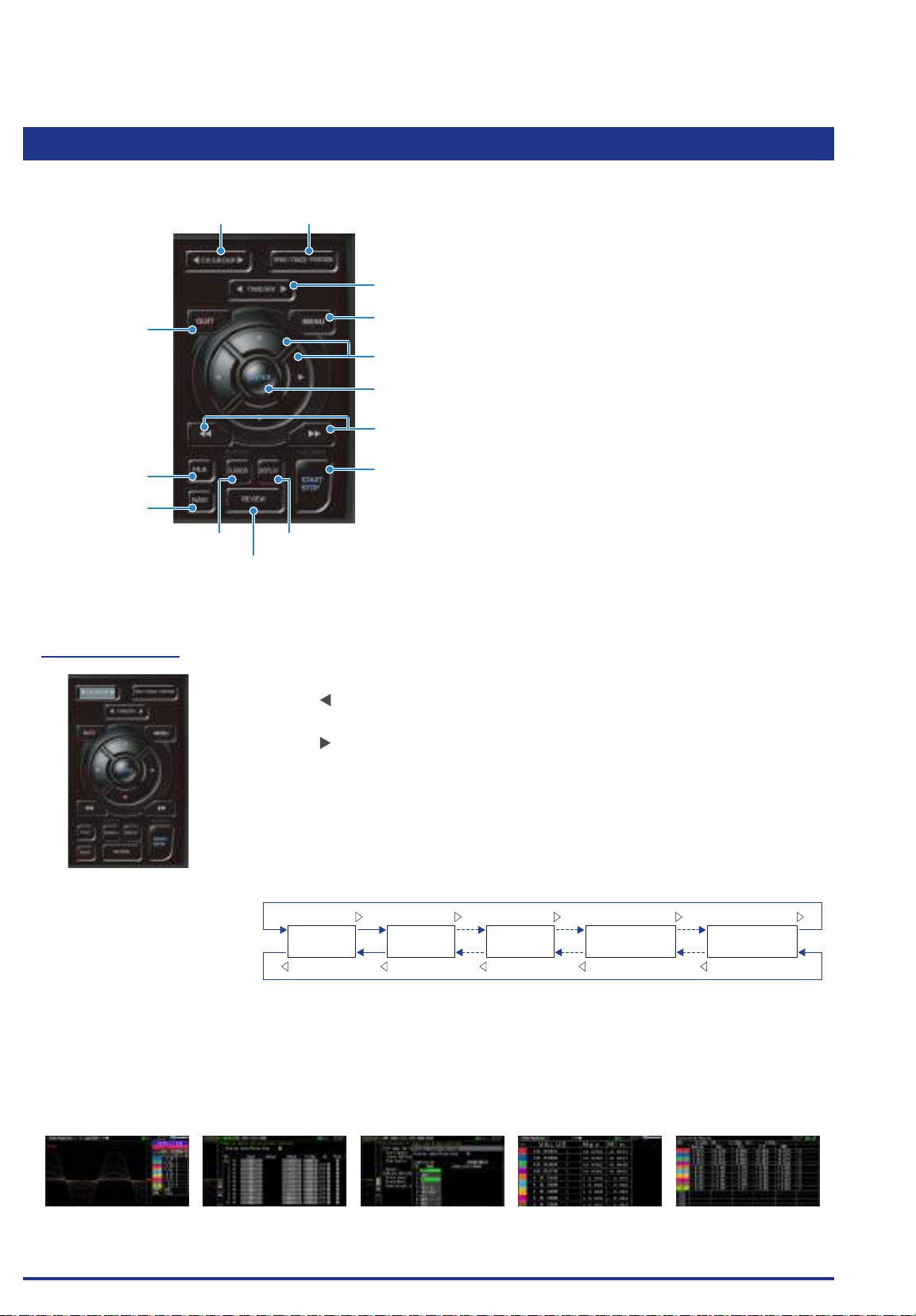
CHAPTER 3 Settings and Measurement
3.2 Key Operation
This section describes key operation.
(1) CH GROUP (2) SPAN/TRACE/POSITION
(3) TIME/DIV
(5) QUIT
(13) FILE
(14) NAVI
(12) CURSOR (ALARM CLEAR)
(1) CH GROUP
(4) MENU
(6) Direction Keys
(7) ENTER
(8) FAST FORWARD key (KEY LOCK)
(9) START/STOP (USB DRIVE)
(11) DISPLAY
(10) REVIEW
Press this key to switch to the next group consisting of 10 channels.
Press the key to switch to the group consisting of the next 10 channels with a
smaller number.
Press the key to switch to the group consisting of the next 10 channels with a
larger number.
* When optional GS sensor and terminal/addapter are connected, they are
displayed in the following group. When the wireless LAN unit (optional) is
installed in the GL840 and the GL100-WL is connected to the GS sensor and
terminal/addapter through the wireless LAN, they are displayed in the last
group.
Terminal unit
1 to 10
Terminal unit
11 to 20
Terminal unit
101 to 200
GS sensor and
terminal/addapter
Wireless module
connection
The items that can be switched in this key are as follows.
• Switch channels of the digital display area
• Switch channels of the AMP settings
• Switch channels of the trigger/alarm level settings
• Switch channels of the calculation display
MONITOR AMP settings Level settings
Find Quality Products Online at: [email protected]
www.GlobalTestSupply.com
Digital + Calculation
Display screen
Statistical calculation
between cursors
3-8
Page 77
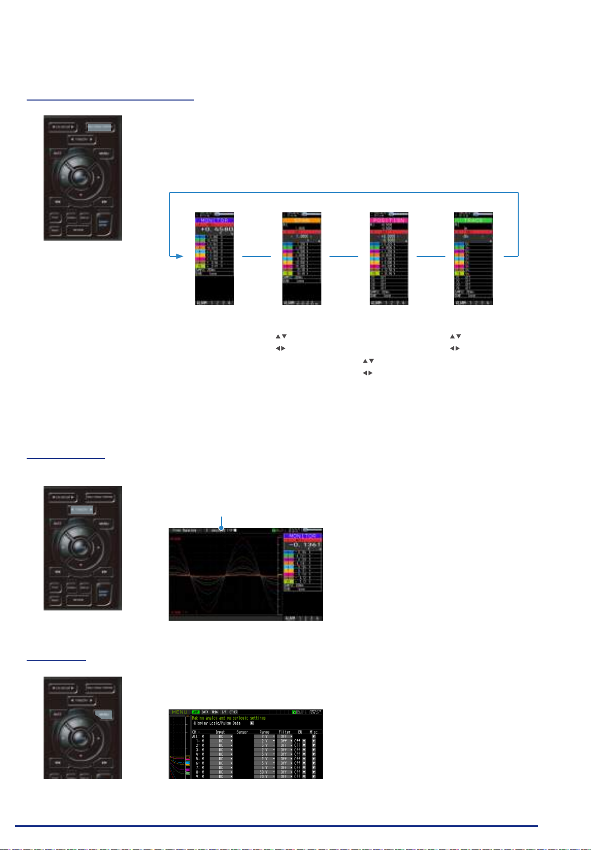
CHAPTER 3 Settings and Measurement
(2) SPAN/TRACE/POSITION
Switches the information in the digital display.
Used to change the settings related to waveform display during Free Running
(when stopped), data capture and data replay.
Pressing this key will switch displays as shown below.
MONITOR SPAN POSITION TRACE
(3) TIME/DIV
Displays digital values
(default status)
Allows changing of the
span value
(waveform amplitude)
• Channel change
: keys
• Amplitude change
: keys
• Change available
: Voltage 8 steps/
Temperature 6 steps
Allows changing of the
position
(waveform up/down
position)
• Range can be
changed in units of
10%
• Channel change
: keys
• Position change
: keys
• Change available
: 10% steps of range
Allows turning ON/
OFF of the waveform
display
• Channel change
: keys
• ON/OFF switch
: keys
• Change available
: ON/OFF
* Data is captured even
if OFF is set.
* When ALL is set, setting values for CH1 is reected on other channels.
When CH1 is OFF, ALL cannot be set.
Press the left/right key of the [TIME/DIV] key to change the time axis display
width.
TIME/DIV display
(4) MENU
Open the settings window to capture data. For details on settings, refer to “3.4
Setting Menus” .
Find Quality Products Online at: [email protected]
www.GlobalTestSupply.com
3-9
Page 78
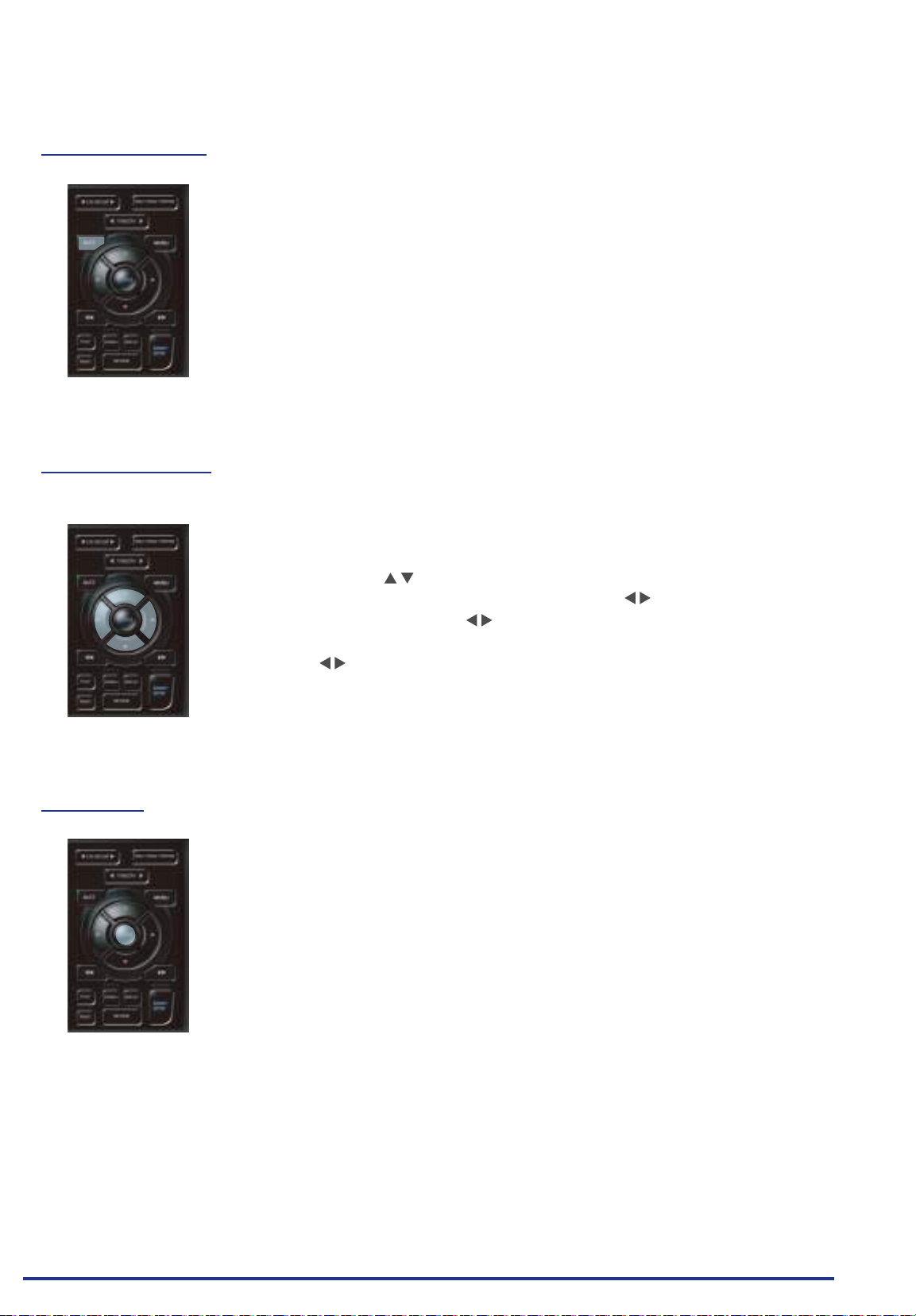
CHAPTER 3 Settings and Measurement
(5) QUIT (LOCAL)
This key is primarily used for the following operations.
• To cancel a setting during menu conguration.
• To return to the MONITOR screen when the SPAN/TRACE/POSITION screen
is displayed.
• To cancel remote status (in which keys are disabled) through interface control.
• To close the menu screen.
• To quit data replay.
(6) Direction Keys
This key is primarily used for the following operations.
• To move a menu or setting item during menu conguration.
• To move the cursor during replay.
• To move the active channel in the Waveform + Digital and Digital + Calculation
Display screens ( keys).
• To change the setting of SPAN/TRACE/POSITION ( keys).
• To change the Quick setting ( keys).
• To change the channel to be displayed in the Digital + Calculation Display
screen ( keys).
(7) ENTER
This key is primarily used for the following operations.
• To nalize setting items during menu conguration or open submenus.
Find Quality Products Online at: [email protected]
www.GlobalTestSupply.com
3-10
Page 79
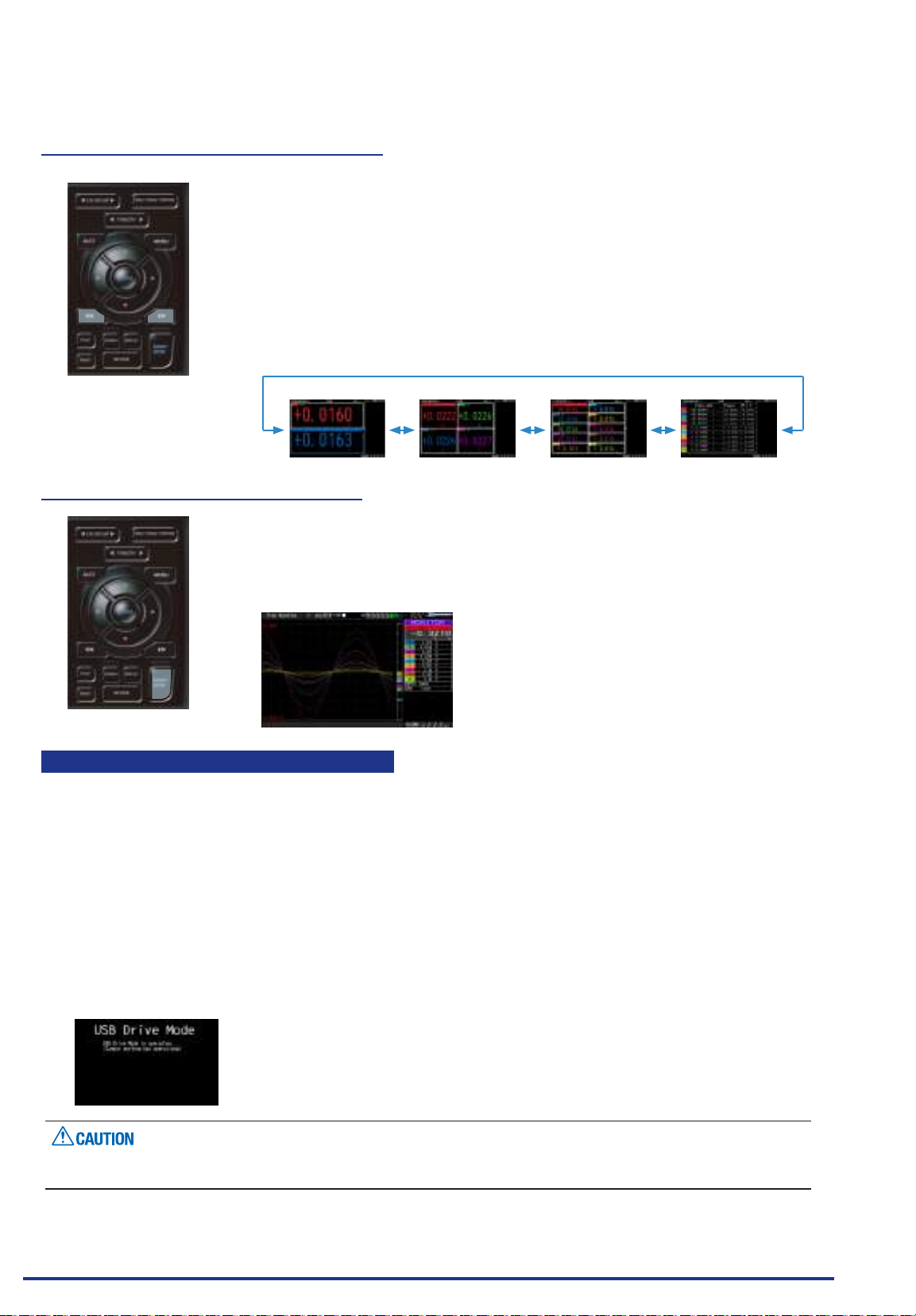
CHAPTER 3 Settings and Measurement
(8) FAST FORWARD key (KEY LOCK)
This key is primarily used for the following operations.
• To move the cursor at high speed during replay.
• To change the display order of the les in the le box.
• To set key lock (Hold down the left/right FAST FORWARD key for at least two
seconds. Press again to unlock)
A password for canceling the key lock can be specied.
Refer to “(14) To cancel key lock by password” in “3.4 Setting Menus” for
details.
• To change the display mode in the Digital + Calculation Display screen.
2ch Mode 4ch Mode 10ch Mode All Mode
(9) START/STOP (USB Drive Mode)
This key performs the following two operations:
<Starts/stops capture>
• During Free Running, starts capture.
• During capture, stops capture.
USB Drive Mode Operation Procedure
In the “USB Drive Mode”, the internal memory (SD1) and SD memory card (SD2) can be check on a PC as
an external storage device.
When two SD memory cards are inserted into the SD CARD 2 (SD2) respectively, they are recognized as
two external storage media.
Since the SD memory card is recognized as a removal disk, this mode facilitates le manipulation such as
transfer and deletion.
1. Use a USB cable to connect the GL840 and a PC.
2. While pressing the GL840 [START/STOP] key, turn the power ON.
3. The external storage media is recognized by the PC and data exchange becomes possible.
* In USB Drive Mode, the display on the GL840 becomes as follows:
To exit USB Drive Mode, turn off and on the power again.
•
In USB Drive Mode, no operation including data capture and data replay is available.
•
Find Quality Products Online at: [email protected]
www.GlobalTestSupply.com
3-11
Page 80
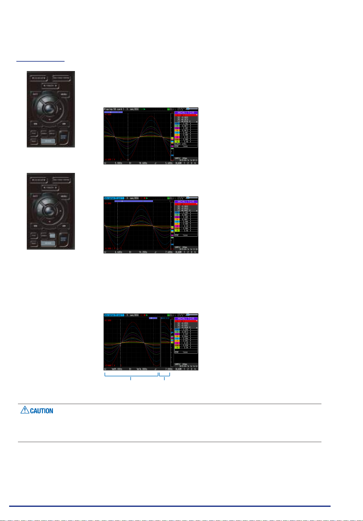
CHAPTER 3 Settings and Measurement
(10) REVIEW
This key is used to replay captured data.
• During Free Running, captured data is replayed.
The screen used to specify the data replay source le appears; specify the
le you want to replay.
• While capturing data, recently captured data is replayed in 2-screen.
<1-screen replay display>
• When the [DISPLAY] key is pressed after the captured data is replayed, the
captured data and current data are replayed in 2-screens consisting of the
captured data screen and current data screen respectively.
Press the [DISPLAY] key again to switch the screen to 1-screen replay
display.
<2-screen replay display>
Captured data Current data
To exit the replay display, press the [QUIT] key.
For CSV-formatted data, only the data captured by this GL840 can be replayed.
Also, when the data captured in CSV format is replayed, the unit of the temperature data is displayed in “deg
C” rather than “°C”.
Find Quality Products Online at: [email protected]
www.GlobalTestSupply.com
3-12
Page 81
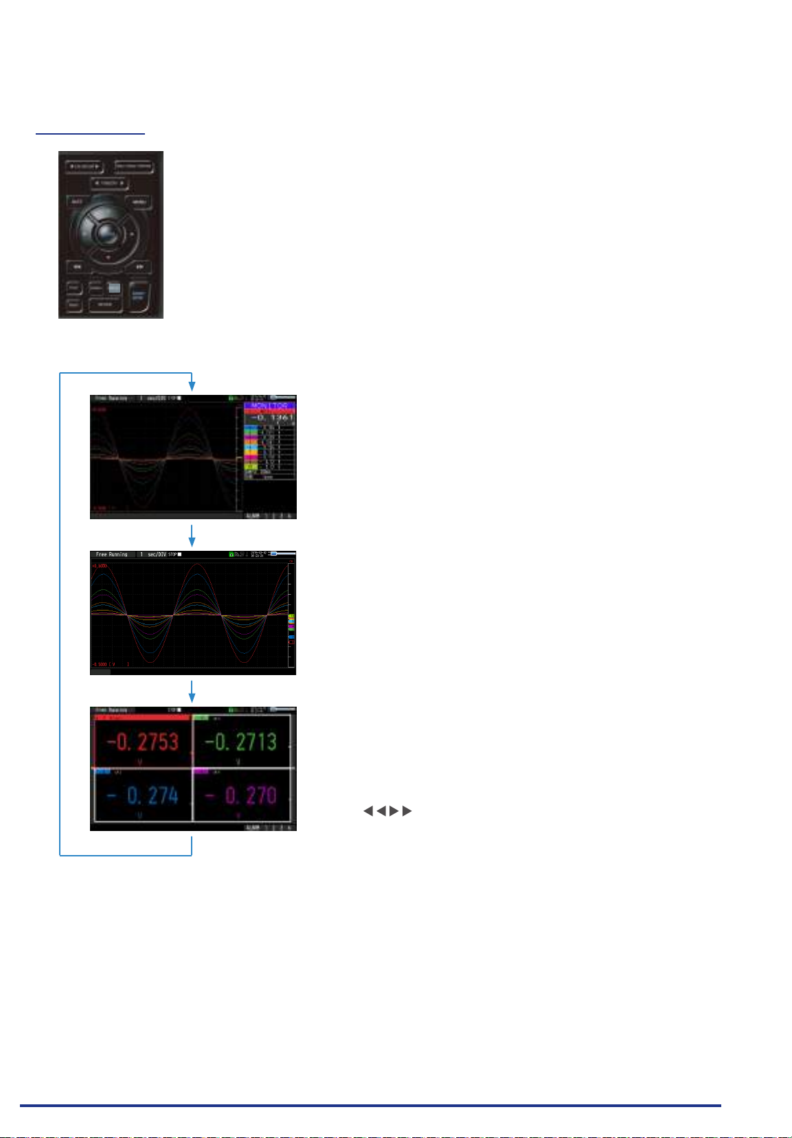
CHAPTER 3 Settings and Measurement
(11) DISPLAY
This key is used to switch the screen mode.
When running free-running (when the recording is stopped), data capturing, and
data replaying during the capture, the screen mode can be switched.
Pressing this key switches the screen display as follows:
<When free-running and data capturing>
<Waveform + Digital Screen>
Displays the waveform and the digital values.
The setting can be changed using the [SPAN/TRACE/
POSITION] key.
<Expanded Waveform screen>
Displays only the waveform expanded in full screen mode.
<Digital + Calculation Display screen>
Displays digital values and two calculation results in large
letters.
The calculation settings can be made using the Data menu.
Refer to “(2) DATA setting” in “3.4 Setting Menus”.
Use the
mode. The calculation results are displayed only when switched
to "All Mode".
Refer to “(8) FAST FORWARD key (KEY LOCK)” in “3.2 Key
Operation” for details on ” All Mode”.
FAST FORWARD keys to change the display
Find Quality Products Online at: [email protected]
www.GlobalTestSupply.com
3-13
Page 82
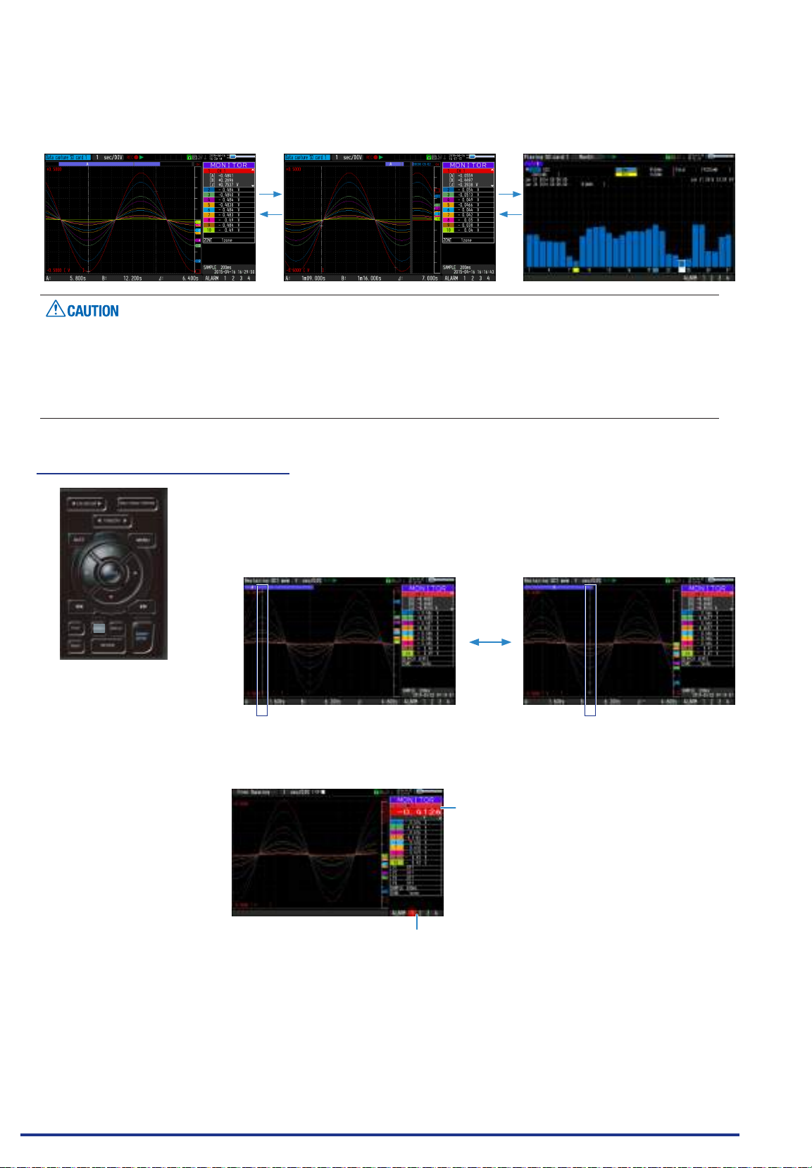
CHAPTER 3 Settings and Measurement
<Data replay during capture>
< Replay screen display> <2-screen replay display> <Integrated bar graph display>
For CSV-formatted data, only the data captured by this GL840 can be replayed.
Also, when the data captured in CSV format is replayed, the unit of the temperature data is displayed in “deg
C” rather than “°C”.
Only when the integrated CH is included in the data, the integrated bar graph can be displayed. For details,
please refer to “(11) Integrated bar graph display” in “3.4 Setting Menus”.
(12) CURSOR (ALARM CLEAR)
• This key is used to switch between cursors A and B during replay.
Pressing this key switches between cursor A and B.
Refer to “(10) Data replay menu” in “3.4 Setting Menus” for details on cursor
operation.
Cursor A Cursor B
Cursor B Cursor A
• When the alarm setting is “Hold generated Alarm”, the maintained alarm is
cleared.
Alarm-generated channels
Alarm output terminal status
• Black : Alarm is not issued
• Red : Alarm is issued
Find Quality Products Online at: [email protected]
www.GlobalTestSupply.com
3-14
Page 83
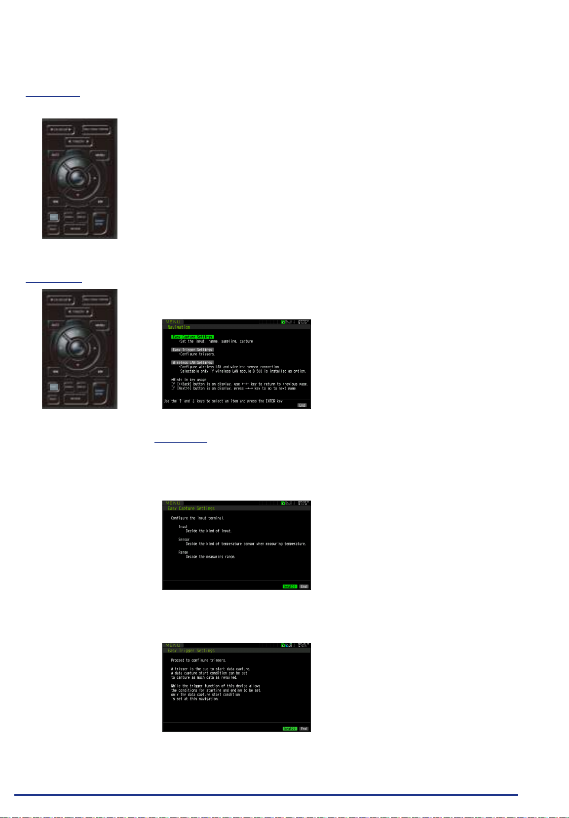
CHAPTER 3 Settings and Measurement
(13) FILE
(14) NAVI
This key is used to perform the le-related operations.
• Performs the operations (copy and delete, etc.) for the internal memory (SD1)
and SD memory card (SD2).
• Performs the screen copy
• Saves all data or data between cursor A and cursor B during replay (can be
set during replay only)
• Saves or reads the currently set condition into the USB device. (can be set
during Free Running only).
• Replaces the SD memory card (SD2) during data capture (Settable when
capturing or backing up to the SD memory card).
Refer to “(7) FILE menu” in “3.4 Setting Menus” for details on le operation.
Press the [NAVI] key during free-running to display the MENU screen for Navigation.
<Navigation display>
Operations
1. Select the “Easy capture setting” and then press the [ENTER] key to display
the following menu screen.
In this screen, you can set the basic settings such as input, sensor, and
range, etc.
2. Select the “Easy trigger setting” and then press the [ENTER] key to display
the following menu screen.
In this screen, you can set the basic trigger settings to start the data capture.
Find Quality Products Online at: [email protected]
www.GlobalTestSupply.com
3-15
Page 84
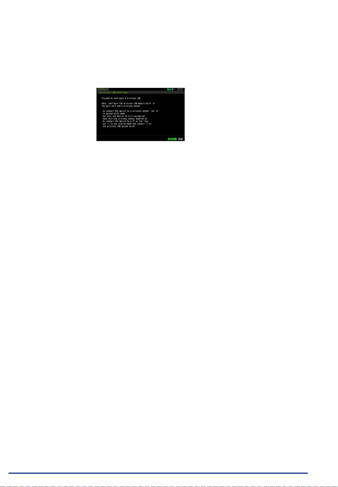
CHAPTER 3 Settings and Measurement
3. Select the “Wireless LAN setting” and then press the [ENTER] key to display
the following menu screen.
This screen is displayed only when optional wireless unit is installed.
In this screen, you can set the basic settings for wireless connection
(connection to wireless sensor or wireless LAN base unit (Router).
The above settings can be performed by following operation instructions on the
screen. Because the setting procedure varies depending on each setting item,
please set in accordance with the instructions on the screen.
Find Quality Products Online at: [email protected]
www.GlobalTestSupply.com
3-16
Page 85
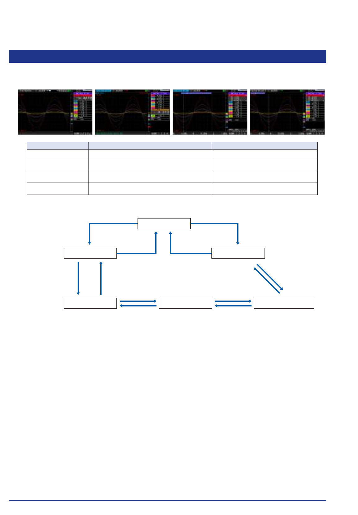
CHAPTER 3 Settings and Measurement
3.3 Operation Modes
You can check the system operation status in the status message display.
< Free Running > < Capturing > <Replaying while capturing data> < Replaying >
Operation Description Simple message display
Free Running Startup status, or data is not being captured. Free Running
Capturing The data is being captured. Capturing the data to SD CARD1 or SD
Replaying while capturing
data
Replaying Captured data is being replayed The data in the SD CARD1 or SD CARD2 is
Replaying the data during capture and displaying the
current waveform
Operation status transition
[START/STOP] key [REVIEW] key
Free Running
CARD2
Capturing the data to SD CARD1 or SD
CARD2
being replayed.
[QUIT] key or [REVIEW] key[REVIEW] key
Replay while capturing
[START/STOP] key
2-screen replaying display
[DISPLAY] key [DISPLAY] key
[QUIT] key
ReplayingCapturing
[DISPLAY] key
Integrated bar graph display
* Only when there is the integrated CH.
Find Quality Products Online at: [email protected]
www.GlobalTestSupply.com
3-17
Page 86
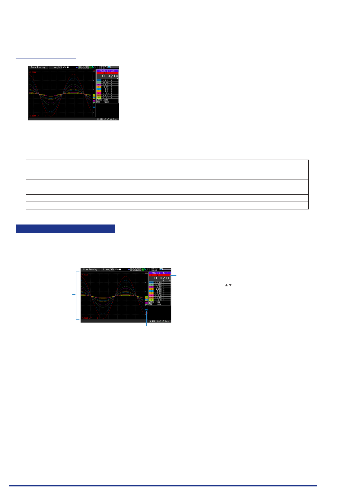
CHAPTER 3 Settings and Measurement
(1) Free Running
In free-running, you primarily perform the settings for data capture.
You can check the currently input signal in the waveform or digital value.
Main operations available during Free Running
Measuement parameters settings The [MENU] key is used to change various setting items in conguration
SPAN/TRACE/POSITION The [SPAN/TRACE/POSITION] key is used to change settings.
Display mode The [DISPLAY] key is used to change the display mode.
File operations The [FILE] key is used to perform le-related operations.
Data replay The [REVIEW] key is used to replay captured data.
Time axis change The [TIME/DIV] key is used to change the time axis scale..
menus.
Operation of screen display
The information in the screen display is changed by switching the channel.
The operation of screen display can be performed during free-running, capturing, and replaying.
<Screen display when the CH1 is selected
on the MONITOR screen during free-running>
The selected channel is enlarged.
The scale of the selected
channel is indicated.
The display channel can be
switched by operating the
The selected channel is displayed without coloration.
keys.
Find Quality Products Online at: [email protected]
www.GlobalTestSupply.com
3-18
Page 87
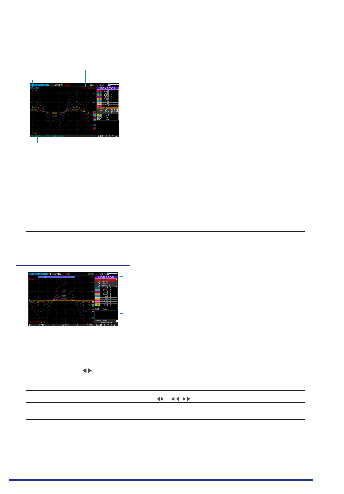
CHAPTER 3 Settings and Measurement
(2) Capturing
The remaining capacity of memory
Time of Capturing
Capture dest inatio n and le n ame
The captured data is saved in the internal memory (SD1) or SD memory card (SD2) during data capture.
You cannot use the [MENU] key to change the setting.
Operations available during capture
SPAN/TRACE/POSITION change Change the settings with the [SPAN/TRACE/POSITION] key.
Screen display mode switch Used to change the screen mode with the [DISPLAY] key.
Replay while capturing Replay the data captured while capturing
Save to device Save to the device with the [FILE] key during data capture.
Setting check Display the setting information with the [MENU] key.
Time axis change Change the time axis with the [TIME/DIV] key.
(Remaining time more than 99999 hours is
displayed as "++++:++:++".)
(3) Data replaying during capture
Displays the voltage at a point
indicated by Cursor A or B or the
selected cursor.
Displays the measurement time at a
point indicated by Cursor A or B or the
selected cursor.
The captured data while capturing can be replayed by pressing the [REVIEW] key.
You can switch between the 1-screen (replayed data) and 2-screen (replayed data during data capture) by
pressing the [DISPLAY] key.
Use the Direction keys ( ) to move the cursor and captured data to check digital values.
Main operations to replay during data capture
Cursor movement The [CURSOR] key is used to switch between cursors A and B.
The or
Save to device The save to the device can be performed from the [FILE] menu.
(The data up to the present or between the cursors can be saved in a
separate le during data capture.)
Screen copy Copy the screen with the [FILE] key.
Switching between 1-screen and 2-screen You can switch between 1-screen and 2-screen during data replaying by
pressing the [DISPLAY] key.
Time axis change Change the time axis with the [TIME/DIV] key.
,
keys are used to move the cursors.
Find Quality Products Online at: [email protected]
www.GlobalTestSupply.com
3-19
Page 88
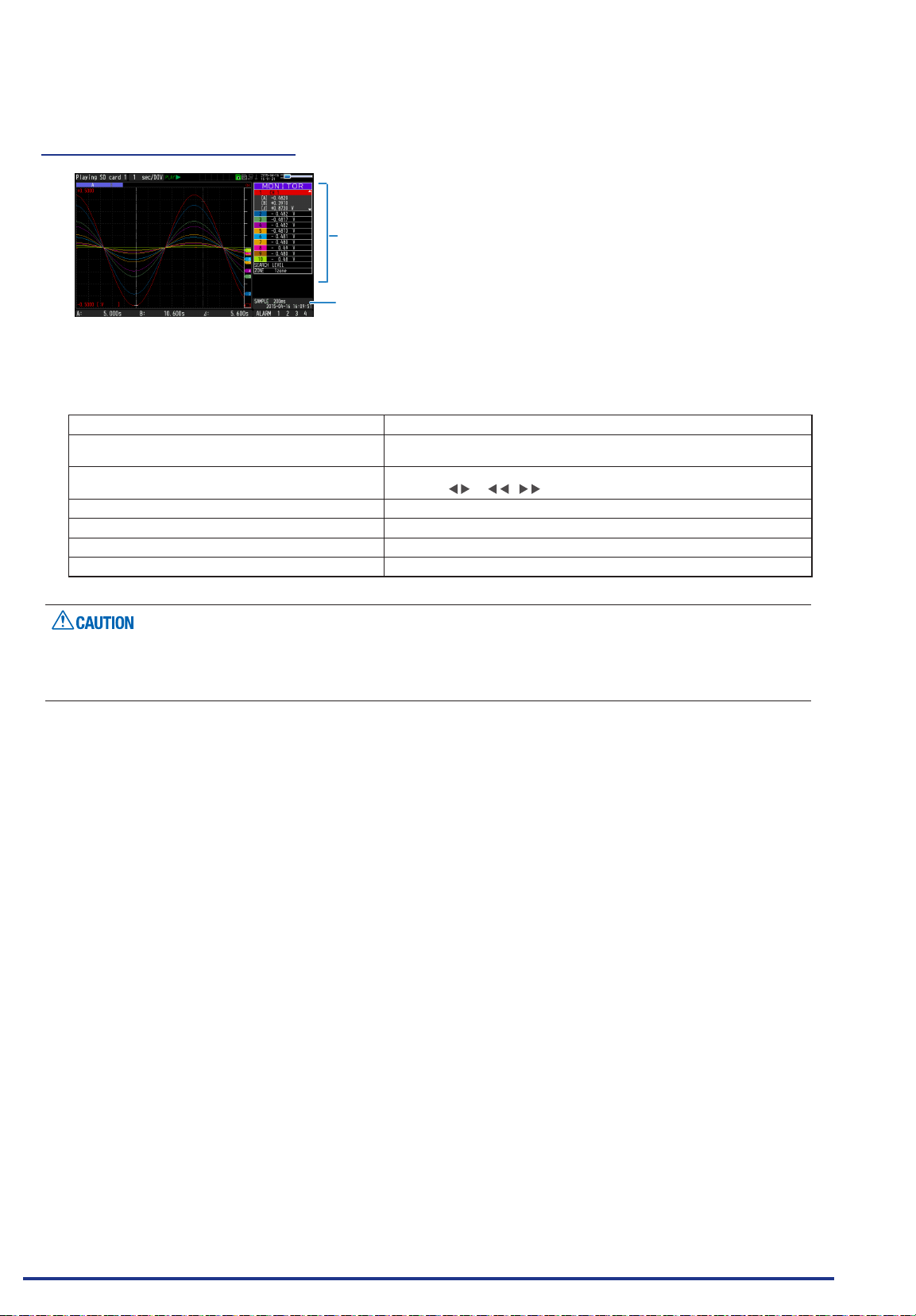
CHAPTER 3 Settings and Measurement
(4) Captured data replaying
Displays the captured data.
Main operations to replay captured data
SPAN/TRACE/POSITION replay Change the settings with the [SPAN/TRACE/POSITION] key.
Operation in the menu during data capture Perform cursor movement, data search, and calculation setting with the
Cursor movement Switch between Cursor A and B with the [CURSOR] key.
Data save Save all the data or data between cursors withy the [FILE] key.
Time axis change Change the time axis scale with the [TIME/DIV] key.
File operation Perform le-related operations
Display copy Copy the screen with the [FILE] key.
Displays the voltage at a point
indicated by Cursor A or B or the
selected cursor.
Displays the measurement time at a
point indicated by Cursor A or B or the
selected cursor.
[MENU] key.
Using the or
,
keys, move the cursor.
For CSV-formatted data, only the data captured by this GL840 can be replayed.
Also, when the data captured in CSV format is replayed, the unit of the temperature data is displayed in “deg
C” rather than “°C”.
Find Quality Products Online at: [email protected]
www.GlobalTestSupply.com
3-20
Page 89
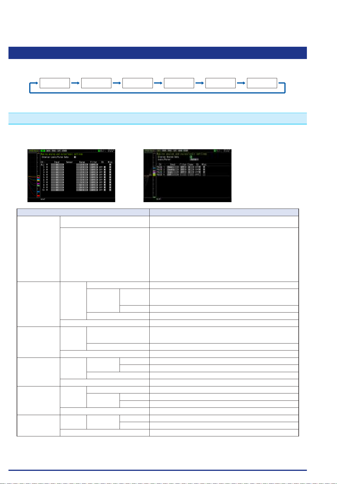
CHAPTER 3 Settings and Measurement
3.4 Setting Menus
When you press the [MENU] key during Free Running, the following menu screens appear.
WLAN ※1 OTHERI/FTRIGAMP DATA
* When optional wireless unit is not installed, these menu screen are not displayed.
(1) AMP settings
This menu is used to specify input signal-related settings.
<Analog settings> <Logic Pulse settings>
Setting Selections available
Input Standard terminal and Withstand high-
Standard terminal
and Withstand
high-voltage highprecision terminal
Temperature and
humidity sensor
(GS-TH)
3-axis acceleration
/ temperature
sensor (GS-3AT)
4ch voltage /
temperature
terminal (GS-4VT)
4ch thermistor
(GS-4TSR)
voltage high-precision terminal
GS sensor and terminal/addapter
(optional)
Range [Voltage] 20, 50, 100, 200, 500mV; 1, 2, 5, 10, 20, 50, 100V; 1-5V
[Temperature] Sensor Thermocouple: TC-K, TC-J, TC-T, TC-R, TC-E, TC-B, TC-S, TC-N,
Range 100, 500, 2000°C
[Humidity] 100% xed
Filter Off, 2, 5, 10, 20, 40
Range [Temperature] / [Dew-point
temperature] / [Accumulated
temperature]
[Humidity] 100% xed
Filter None
Range [Acceleration] Sensor Peak / Ave. / RMS
Range 2, 5, 10G; 20, 50, 100m/s2
[Humidity] 100% xed
Filter None
Range [Voltage] 20, 50, 100, 200, 500mV; 1, 2, 5, 10, 20, 50V; 1-5V
[Humidity] Sensor Thermocouple: TC-K , TC-T
Range 2000°C xed
Filter None
Range [Humidity] Sensor Thermistor: TSR-A, TSR-J
Range 200°C xed
Filter None
Off, DC, TEMP, RH
Temperature and humidity sensor (GS-TH): Off, TEMP, DEW, ACC.
TEMP
3-axis acceleration / temperature sensors (GS-3AT): Off, TEMP /
ACC. X / ACC. Y / ACC. Z
4ch voltage / temperature terminal (GS-4VT): Off, DC, TEMP
4ch thermistor (GS-4TSR): Off, TEMP
Illumination / ultraviolet sensor (GS-LXUV): Off, ILLUM. / UV / ACC.
ILLUM. / ACC. UV
CO2 sensor (GS-CO2): Off, CO2
Adapter for AC current sensor (GS-DPA-AC): Off, CURRENT /
POWER, ACC. POWER
TC-W
Resistance bulb: Pt100, JPt100, Pt1000
100°C xed
Find Quality Products Online at: [email protected]
www.GlobalTestSupply.com
3-21
Page 90
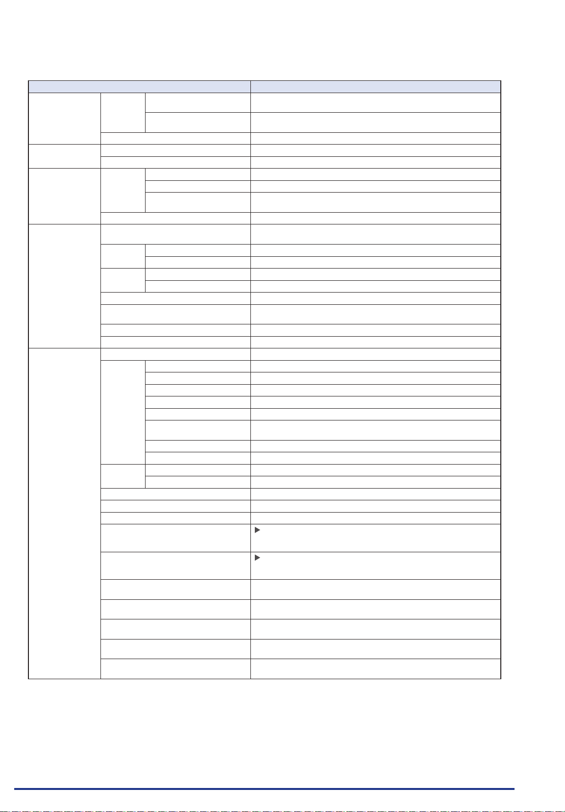
CHAPTER 3 Settings and Measurement
Setting Selections available
Illumination /
ultraviolet sensor
(GS-LXUV)
CO2 sensor
(GS-CO2)
Adapter for AC
current sensor
(GS-DPA-AC)
EU
(Scaling settings)
Misc. Annotation text string Enter text (Max. 31 characters)
Range [Illuminance] / [Accumulated
Filter None
Range 5000ppm xed
Filter None
Range AC clamp mode AC 1P2W, AC 1P3W, AC 3P3W
Filter None
Function Off, On
Meas. Value
EU output Upper limit Set numeric value
Dec pt EU output upper limit x 0.01, x 1, x 10, x 100, x 1000
Select Cur, Length, Area, Volume, Velocity, Accel, Freq, Mass, Energy,
Unit (The selections vary depending on the unit selected in the above.)
Arbitrary unit Enter text (Max. 8 characters)
InterCH Op
Settings
Span
settings
Waveform color setting 0 to 31 for each of red, green, blue (RGB)
Line Thickness Setting 1 to 8 dots
Trace setting Off, On
Perform Auto Zero ADJ.
* When using the GS-3AT, the auto
balance is performed.
Reset Auto Zero ADJ.
* When using the GS-3AT, the auto zero
is released.
Accumulated reference temperature
Accumulated polarity High/Low
CO2 calibration Off, On
Voltage 90 to 264
Power factor 0.30 to 1.00
illuminance]
[Ultraviolet] / [Accumulated
ultraviolet]
[Current] 50, 100, 200A
[Power] / [Accumulated
power]
Upper limit Set numeric value
Lower limit Set numeric value
Lower limit Set numeric value
Function Off, On
Operation CH-X (+, -, x, /) CH-Y
Scaling /1000000, /1000, ×1, ×1000, ×1000000
Upper/Lower limit Set numeric value
Dec pt ×1, ×10, ×100, ×1000, ×10000
Select Cur, Length, Area, Volume, Velocity, Accel, Freq, Mass, Energy,
Unit (The selections vary depending on the unit selected in the above.)
Arbitrary unit Enter text
Upper limit Set numeric value
Lower limit Set numeric value
2000, 20000lx, 200klx
30mW/cm2 xed
(20, 50, 100kW) Change in synchronization with the current range.
* When measuring the humidity, “On” is xed.
Pressure, Flow , Temp, Strain, Brightness,Concentration
Pressure, Flow , Temp, Strain, Brightness,Concentration
Press right key to execute.
* This function is not available for the temperature setting.
Press right key to execute.
* This function is not available for the temperature setting.
-20 to +85°C
* Available for GS-TH sensor only.
* Available for GS-TH sensoronly.
* Available for GS-CO2 sensor only.
* Available for GS-DPA-AC adapter only.
* Available for GS-DPA-AC adapter only.
Find Quality Products Online at: [email protected]
www.GlobalTestSupply.com
3-22
Page 91
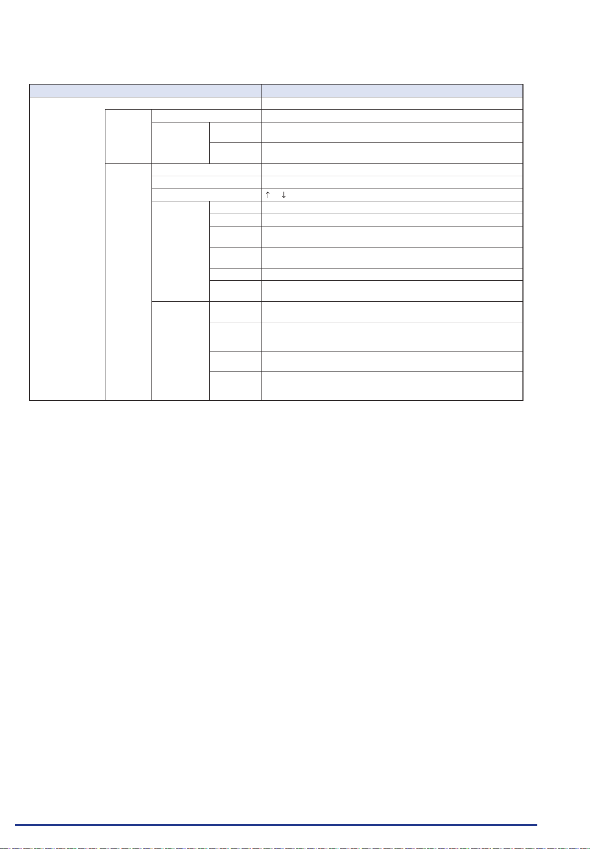
CHAPTER 3 Settings and Measurement
Setting Selections available
Logic/Pulse Off, Logic, Pulse
[Logic] Filter Off, On
Misc. Waveform
color setting
Trace
setting
[Pulse] Input Off, Revolution counts, Counts, Inst.
Filter Off, On
Slope H, L
EU Function Off, On
Meas. Value Set numeric value
EU output
value
Select Cur, Length, Area, Volume, Velocity, Accel, Freq, Mass, Energy,
Unit (The selections vary depending on the unit selected in the above.)
Arbitrary
unit
Misc. Waveform
color setting
Line
Thickness
Setting
Trace
setting
Number of
pulses per
revolution
0 to 31 for each of red, green, blue (RGB)
Off, On
Set numeric value
Pressure, Flow , Temp, Strain, Brightness,Concentration
Enter text
0 to 31 for each of red, green, blue (RGB)
1 to 8 dots
Off, On
1 to 10000
Find Quality Products Online at: [email protected]
www.GlobalTestSupply.com
3-23
Page 92
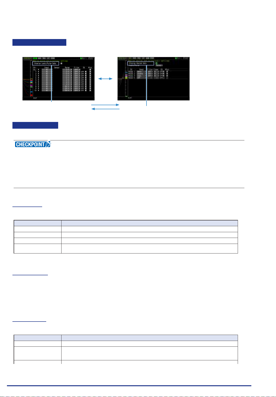
CHAPTER 3 Settings and Measurement
Switching displays
Analog and logic/pulse can be switched as shown below.
• Display Logic/Pulse Data
• Display Analog Data
Analog settings
Species the conditions for analog signals.
When you use CH ALL to set an input, range and lter, all channels are set to the same values if the input
is the same. Range is set only for the same input channels. However, the range of a channel is not changed
if its EU (scaling) is set to On.
Span All Settings is set only for the same range channels.
* If the rst channel in a channel group (CH1 if CHs 1 to 10 are displayed) has an input that is set to Off, the
input of CH ALL is set to Off.
(1)-1 Input
This is used to select input condition
Selection item Description
Off Input signal measurement is disabled. No waveform or digital value is displayed.
DC Used for measuring direct-current voltage.
TEMP Used for measuring temperature.
RH Used for measuring humidity with the humidity sensor B-530.
In this case, the voltage range will become 1 V, and the EU settings will not be available.
(1)-2 Sensor
This is used to select the thermocouple connected when the temperature is input and type of resistance
bulb. Additionally, perform the settings for sensor operation when connecting the optional GS sensor or
terminal/addapter. For details, refer to “
* The
symbols indicate the abbreviation of name (model).
*****
*****
setting”.
(1)-3 Range
This is used to select the range of measurement.
Input item Description
DC 20, 50, 100, 200, 500 mV; 1, 2, 5, 10, 20, 50, 100V 1-5 V
TEMP 2000, 500, 100℃
RH No selection available
Find Quality Products Online at: [email protected]
* Please select each GS sensor and terminal/addapter in reference to "
* The
symbols indicate the abbreviation of name (model).
*****
3-24
* This setting is used for only standard terminal, Withstand high-voltage high-precision terminal. The
resolution varies depending on the range.
www.GlobalTestSupply.com
setting" described below.
*****
Page 93
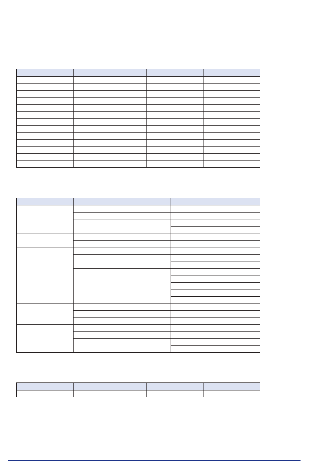
CHAPTER 3 Settings and Measurement
Available SPAN Settings
<Voltage Ranges>
Range Maximum SPAN Minimum SPAN Minimum Resolution
20mV
50mV
100mV
200mV
500mV
1V
2V
5V
10V
20V
50V
100V
1-5V
-
22.000 to +22.000mV 0.200mV 0.001mV
-
55.00 to +55.00mV 0.50mV 0.01mV
-
110.00 to +110.00mV 1.00mV 0.01mV
-
220.00 to +220.00mV 2.00mV 0.01mV
-
550.0 to +550.0mV 5.0mV 0.1mV
-
1.1000 to +1.1000V 0.0100V 0.0001V
-
2.2000 to +2.2000V 0.0200V 0.0001V
-
5.500 to +5.500V 0.050V 0.001V
-
11.000 to +11.000V 0.100V 0.001V
-
22.000 to +22.000V 0.200V 0.001V
-
55.00 to +55.00V 0.50V 0.01V
-
110.00 to +110.00V 1.000V 0.01V
-
5.500 to +5.500V 0.050V 0.001V
<Temperature Ranges>
Type Humidity Range Resolution Measurement range
R/S 100℃ F.S. 0.01℃ 0 to 100℃
500℃ F.S. 0.05℃ 0 to 500℃
2000℃ F.S. 0.1℃ R : 0 to 1600℃
B 500℃ F.S. 0.05℃ 400 to 500℃
2000℃ F.S. 0.1℃ 500 to 1820℃
K/E/T/J/N 100℃ F.S. 0. 01℃
500℃ F.S. 0.05℃ K/E/J/N : -200 to 500℃
2000℃ F.S. 0.1℃ K : -200 to 1370℃
W 100℃ F.S. 0. 01℃ 0 to 100℃
500℃ F.S. 0.05℃ 0 to 500℃
2000℃ F.S. 0.1℃ 0 to 2000℃
Pt 100℃ F.S. 0.01℃
500℃ F.S. 0.05℃
2000℃ F.S. 0.1℃ Pt100 : -200 to 850℃
S : 0 to 1760℃
-
100 to 100℃
T : -200 to 400℃
E : -200 to 800℃
T : -200 to 400℃
J : -200 to 1100℃
N : -200 to 2000℃
-
100 to 100℃
-
200 to 500℃
JPt100/Pt1000 : -200
to
500
℃
<Humidity Range>
Range Maximum SPAN Minimum SPAN (p-p) Minimum Resolution
100% 0 to +110% 1.0% 0.1%
Find Quality Products Online at: [email protected]
www.GlobalTestSupply.com
3-25
Page 94
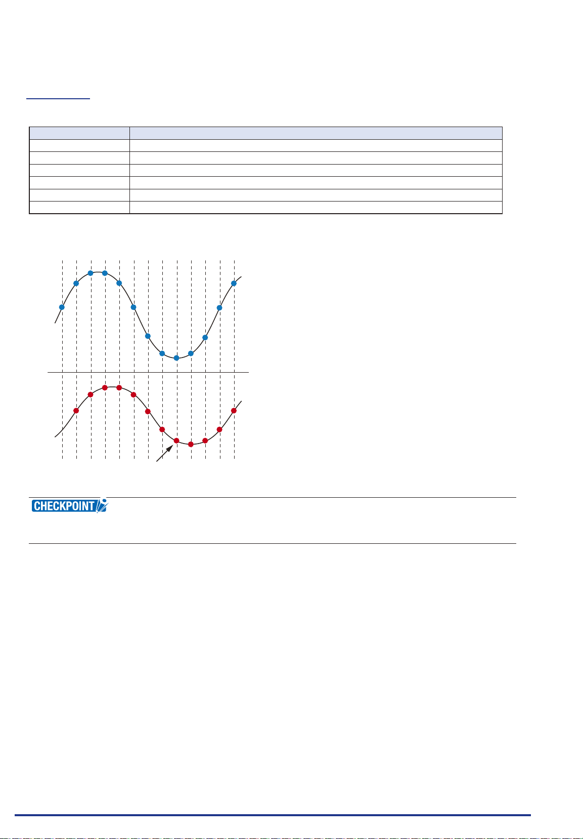
CHAPTER 3 Settings and Measurement
(1)-4 Filter
Selects the range to be measured.
Selection item Description
Off No moving average is calculated.
2 A moving average is calculated 2 times per sampling interval.
5 A moving average is calculated 5 times per sampling interval.
10 A moving average is calculated 10 times per sampling interval.
20 A moving average is calculated 20 times per sampling interval.
40 A moving average is calculated 40 times per sampling interval.
<Filter processing>
Filter processing performed on the GL840 is the moving average shown in the following gure.
n-4
n-3
n-2
n-1
n
D
If the l ter setting is 5,
The moving average is “D=((n-4)+(n-3)+(n-2)+(n-1)+ n)÷5”.
If the sample interval exceeds 30 seconds, the average value of data obtained in a sub-sample (30
seconds) is used.
Find Quality Products Online at: [email protected]
www.GlobalTestSupply.com
3-26
Page 95
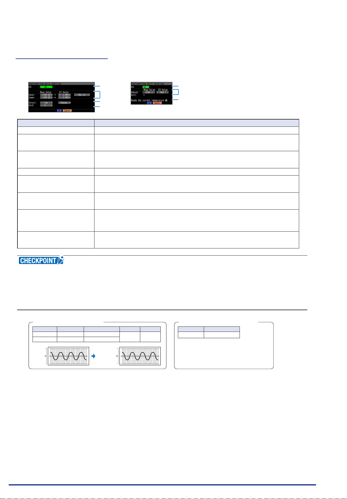
CHAPTER 3 Settings and Measurement
Setting example: For voltage input
Setting example: For temperature input
(1)-5 EU (Scaling settings)
This is used to convert the measured signals to other units.
<For voltage input> <For temperature input>
(1)
(2) (3) (4)
(5)
(6)
Setting Description
(1) EU Function Sets the scaling function to ON or OFF.
(2) Meas. Value (Upper/Lower) Sets the upper and lower limits of values to be converted.
* For temperature input, there is no distinction between upper and lower limits. See the
setting examples shown below for details.
(3) EU Output Value (Upper/
Lower)
Sets the upper/lower limit output values after conversion.
* For temperature input, there is no distinction between upper and lower limits. See the
setting examples shown below for details.
(4) Dec pt Sets the decimal point position for an EU output value.
(5) Select Selects a specic engineering unit classication. (The following are available.)
Cur, Length, Area, Volume, Velocity, Accel, Freq, Mass, Energy, Pressure, Flow , Temp,
Strain, Brightness,Concentration
(6) Unit Selects a unit to be used after conversion. A unit displayed in this eld belongs to the
classication selected in "Select." To set a unit not displayed in this eld, set arbitrary text in
"Arbitrary unit." The setting selected in this eld is displayed in "Arbitrary unit."
(7) Arbitrary Unit Sets a unit to be used after conversion.
Arbitrary text consisting of alphabetical characters and numerical values can be set as a unit.
(For the character input, refer to “(9) Character string input” in “3.4 Setting Menus”.)
When “Select Unit” or “Unit” is specied, it is reected in here.
(8) Reads the current temperature
measurement value
Substitutes the current measurement value into (2) Measurement value and (3) EU output
value.
* The value is not substituted when burnout occurs or the scale is exceeded.
(1)
(2) (3)
(8)
If a message window opens, follow the instruction in the message to change the setting value.
•
The Scaling function performs calculation using a ratio of the Meas. Value and EU Output Value settings.
•
The digital display shows “++++/----” when the converted value cannot be processed by the GL840.
The span may be changed depending on the Scaling settings.
•
For temperature input, the offset setting for an input value is used.
•
+5 V
CH.1 10V
-5 V
Meas. Value
+5.000Upper limit
-5.000Lower limit
EU Output Value
+20.00
-20.00
+ 20.00 rpm
CH.1 Scaling 1
- 20.00 rpm
Dec pt
+ xx.xx
Choose
rpm
Meas. Value
22.0℃
3°C is always added to the measurement value
EU Output Value
25.0℃
Find Quality Products Online at: [email protected]
www.GlobalTestSupply.com
3-27
Page 96
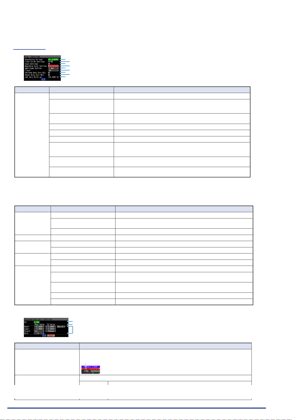
CHAPTER 3 Settings and Measurement
(1)-6 Misc.
(1)
(2)
(3)
(4)
(5)
(6)
(7)
(8)
(9)
Setting object Setting Description
Voltage,
humidity,
acceleration
settings
(1) Annotation Settings Set the annotation (comment) displayed in the CH.
(2) Inter-CH Op Settings Sets what to do in calculation between channels.
(3) Span Settings Sets the upper and lower limits of values of a span in which a waveform
(4) Waveform Color Setting 0 to 31 for each of red, green, blue (RGB)
(5) Line Thickness Setting Setting 1 to 8 dots
(6) Trace This is used to set the waveform display.
(7) Perform Auto Zero ADJ.
(Auto balance in the case of
acceleration)
(8) Reset Auto Zero ADJ. Reset the zero point voltage value (acceleration value).
(9) [Set Zero Point as :] The zero point voltage value (acceleration value) is displayed.
Four arithmetic operations (+, -, x, ÷) can be set as calculation between
channels.
should be displayed.
The current input voltage (acceleration value) is calculated as a zero
point voltage value (acceleration value).
Automatic adjustable voltage range is within ±10% of set range.
* When the temperature is set, this function is not available.
* When the temperature is set, this function is not available.
When GS sensor and terminal/addapter are used
*
For the number in the setting items in the following table, refer to the voltage, humidity and acceleration
settings described above.
Setting object Setting Description
Temperature
setting
Logic setting (5), (6) Same content as the voltage.
Pulse setting (4), (5), (6) Same content as the voltage.
CO2 setting (1), (2), (3), (4), (5), (6) Same content as the voltage.
AC clamp setting (1), (2), (3), (4), (5), (6) Same content as the voltage.
<Inter-CH Op Settings>
(1), (2), (3), (4), (5), (6) Same content as the voltage.
Accumulated reference
temperature
Set the reference temperature accumulated within the range of -20 to
+85°C for the temperature and humidity sensor.
Accumulated polarity Set High/Low accumulated polarity.
Number of pulses per revolution Set the number of pulses per revolution.
CO2 calibration Set the CO2 calibration.
Voltage (Power only) Set the measurement voltage value to calculate the power within the
range of 90 to 264V.
Power factor (Power only) Set the power factor to calculate the power within the range of 0.30 to
1.00.
Auto zero adjustment Display the input voltage after releasing the zero point voltage value.
Zero adjustment reset Display the zero point voltage value. (Display only)
(1)
(2) (3)
(4) (5) (6) (7) (8)
Setting Description
(1) Inter-CH Op Settings Function Off, On
If this setting is ON, the channel has a calculation mark in the digital display, etc.
Calculation mark
(2) Operation CH-X (Function) CH-Y
CH-X CH1 to CH200
Find Quality Products Online at: [email protected]
Function Four arithmetic operation functions (+, -, x, /)
CH-Y CH1 to CH200
www.GlobalTestSupply.com
3-28
Page 97
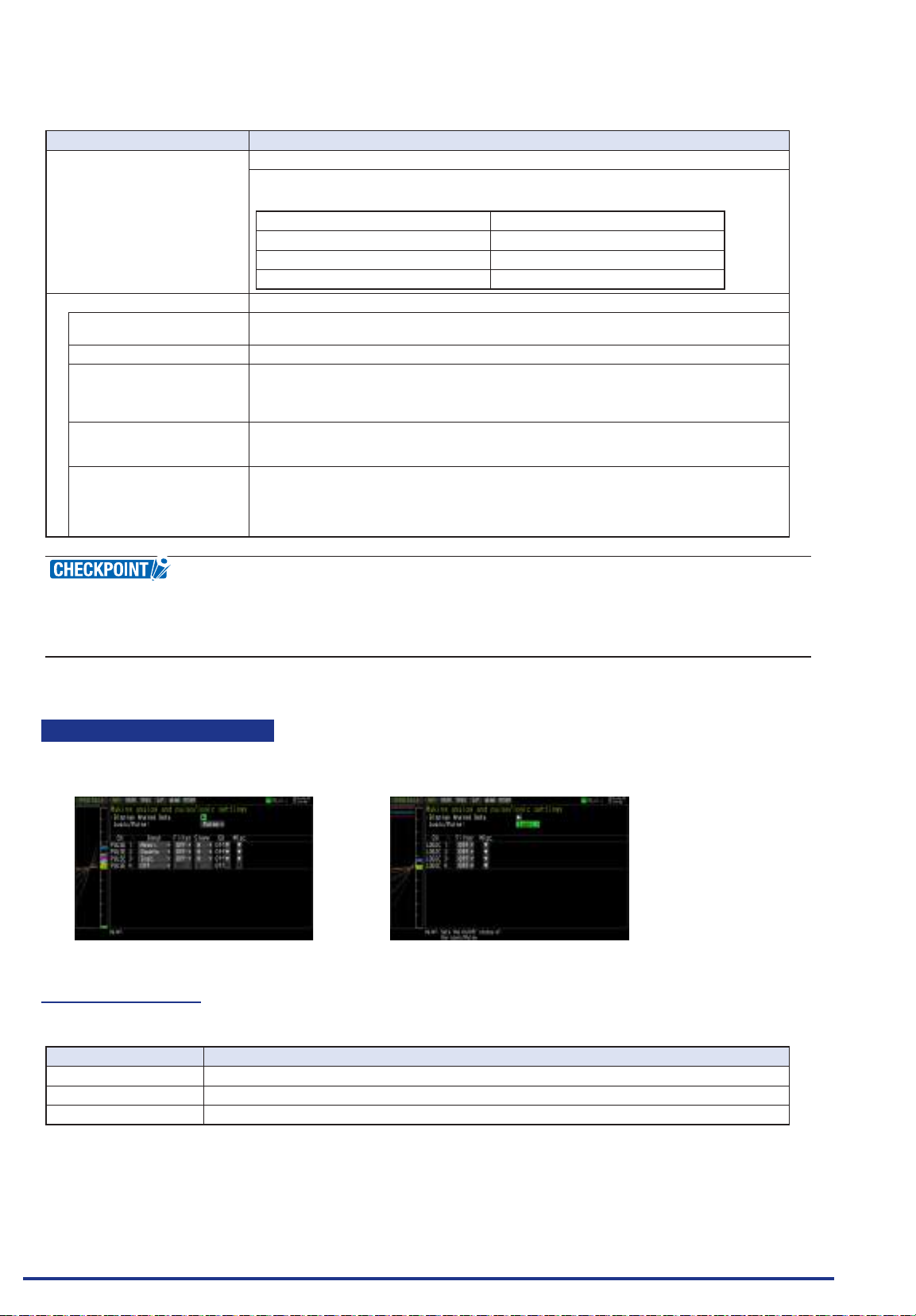
CHAPTER 3 Settings and Measurement
Setting Description
(3) Scaling /1000000, /1000, ×1, ×1000, ×1000000
Sets the scaling factor for a calculation result.
<Example>
In the case of calculation result = 0.001 In the case of calculation result = 1000
Calculation result ×1 = 0.001 Calculation result ×1 = 1000
Calculation result ×1000 = 1 Calculation result / 1000 = 1
Calculation result ×1000000 = 1000 Calculation result / 1000000 = 0.001
Operations span
(4) Upper/Lower limits Sets the upper and lower limits of values of a span in which a waveform should be displayed.
(5) Dec pt Sets the decimal point position for a span setting.
(6) Scaling setting Selects the unit after conversion.
(7) Select Selects the unit which indicates the calculation results.
(8) Unit Sets a unit to be used after conversion.
The setting value is in reference to a calculation result.
The unit displayed here is the unit selected in the "Unit select".
When using the unit not displayed here, set any character in the “Arbitrary unit”. Also, the
contents set here is displayed in the “Arbitrary unit”.
Cur, Length, Area, Volume, Velocity, Accel, Freq, Mass, Energy, Pressure, Flow , Temp,
Strain, Brightness,Concentration
Arbitrary text consisting of alphabetical characters and numerical values can be set as a unit.
(For the character input, refer to “(9) Character string input” in “3.4 Setting Menus”.)
When “Select Unit” or “Unit” is specied, it is reected in here.
When "Select" or "Choose" is used, the setting is reected in this eld.
Calculation results are displayed in volts.
•
The calculation result for 100 mV + 100 mV is 0.2.
Use Scaling to display this result as 200 mV.
Logic and Pulse settings
Makes settings related to digital input.
<For Pulse> <For Logic>
(1)-7 Logic/Pulse
This is used to select the processing method for digital input.
Selection item Description
Off Digital input measurement is disabled.
Logic Digital input is processed as logic signals.
Pulse Digital input is processed as pulse signals.
Find Quality Products Online at: [email protected]
www.GlobalTestSupply.com
3-29
Page 98
CHAPTER 3 Settings and Measurement
MSB LSB
(1)-8 Input
This is used to set the pulse measurement mode. This setting is available only if Pulse is selected in (1)-7.
Selection item Description
Off Pulse input measurement is disabled.
Revol. The number of pulses per sample interval is counted and converted to the number of revolutions per
Counts Captures the cumulative number of pulses for each sampling interval from the start of measurement.
Inst. Captures the number of pulses for each sampling interval.
minute.
(1)-9 Filter
This is used to set the lter for input.
Selection item Description
Off Disables hardware lter.
On Enables hardware lter. It is effective in a noisy environment.
The lter is approximately 30 Hz (-3 dB).
(1)-10 Pulse Slope
This is used to set the slope (direction) to count the number of pulses. This setting is available only if Pulse
is selected in (1)-7.
Selection item Description
H Counts the rising edges of pulses.
L Counts the falling edges of pulses.
Allocation of CH number of logic and pulse data is as shown below.
•
31 30 29 28 27 26 25 24 23 22 21 20 19 18 17 16 15 14 13 12 11 10 9 8 7 6 5 4 3 2 1 0
Bit 8 to 11: Wireless sensor 1 data
Bit 4 to 7: GS sensor data
Bit 12 to 15: Wireless sensor 2 data
Bit 16 to 19: Wireless sensor 3 data
Bit 20 to 23: Wireless sensor 4 data
Bit 24 to 27: Wireless sensor 5 data
Bit 0 to 3: Main unit data
Find Quality Products Online at: [email protected]
www.GlobalTestSupply.com
3-30
Page 99
CHAPTER 3 Settings and Measurement
Setting example
(1)-11 EU (Scaling settings)
This is used to convert the measured signals to other units. This setting is available only if Pulse is selected in (1)-7.
(1)
(2) (3) (4) (5) (6)
Setting Description
(1) EU Function Sets the scaling function to ON or OFF.
(2) Meas. Value Sets a value to be converted.
(3) EU Output Value Sets an output value after conversion.
(4) Select Selects a specic engineering unit classication.(The following are available.)
(5) Unit Selects a unit to be used after conversion.
(6) Arbitrary Unit Sets a unit to be used after conversion.
Cur, Length, Area, Volume, Velocity, Accel, Freq, Mass, Energy, Pressure, Flow , Temp,
Strain, Brightness,Concentration
A unit displayed in this eld belongs to the classication selected in "Select." To set a unit not
displayed in this eld, set arbitrary text in "Arbitrary unit."
The setting selected in this eld is displayed in "Arbitrary unit."
Arbitrary text consisting of alphabetical characters and numerical values can be set as a unit.
(For the character input, refer to “(9) Character string input” in “3.4 Setting Menus”.)
When “Select Unit” or “Unit” is specied, it is reected in here.
When "Select" or "Unit" is used, the setting is reected in this eld.
If a message window opens, follow the instruction in the message to change the setting value.
•
The Scaling function performs calculation using a ratio of the Meas. Value and EU Output Value settings.
•
The digital display shows “++++/----” when the converted value cannot be processed by the GL840.
•
The span may be varied depending on the scaling settings.
•
EU Output ValueMeas. Value
8001000
2000
1000
CH.1
0
Dec pt
+ xx.xx
800
CH.1 Scaling 1
Choose
rpm
0
(1)-12 Misc.
<For Pulse>
(1)
(2)
(3)
(4)
Setting Description
(1) Waveform Color Setting 0 to 31 for each of red, green, blue (RGB)
(2) Line Thickness Setting 1 to 8 dots
(3) Trace This is used to set the waveform display.
(4) Number of pulses per
revolution
Find Quality Products Online at: [email protected]
1 to 10000
When setting the pulse input to the number of revolutions, set the number of pulses per
revolution.
As the number of pulses per revolution set here is 1 revolution, the number of revolutions per
minute (RPM) is calculated.calculated. For example, if “100” is set, 1 rotation is judged when
100 pulses have been input.
<Calculation formula>
Number of revolutions (RPM) = Pulse input frequency ÷ Number of pulses per revolution x
60 (1 minute)
<Example>
Number of pul
Pulse input: 1000 Hz (1000 pulses per sec.)
Number of revol
<For Logic>
(1)
(3)
ses per revolution: 100 (1 rotation is judged when 100 pulses have been input.)
www.GlobalTestSupply.com
utions: 600 RPM (600 rotation per min.)
3-31
Page 100
CHAPTER 3 Settings and Measurement
Temperature and humidity sensor (GS-TH: optional) setting
Performs the setting related to the input of temperature and humidity sensor.
The Setting screen is displayed at the end of the group by connecting the temperature and humidity sensor
and turning On the GL840’s power.
(1)-13 Input settings
Setting Description
Off The input signal is not measured. The waveform and digital display also are not performed.
1ch TEMP Used to measure the temperature
2ch RH Used to measure the humidity.
3ch DEW Used to measure the dew-point temperature.
4ch ACC. TEMP Used to measure the accumulated temperature.
5ch to 8ch No AMP When connecting the two GS series and terminal / addapter using a branch adapter for GS, the
following combination is displayed.
Combination CH1 to 4 CH5 to 8
TH+LXUV TH LXUV
TH+CO2 TH CO2
LXUV+CO2 LXUV CO2
Symbols in the table are as follows:
TH: Temperature and humidity sensor
LXUV: Illumination / ultraviolet sensor
CO2: CO2 sensor
(1)-14 Range settings
This is used to select the voltage range to be measured. The temperature range is xed.
Setting Description
TEMP 100℃ xed range
RH 100% xed range
(1)-15 EU setting
The offset of temperature/dew point temperature only can be adjusted.
Refer to “EU Function, Meas. Value, EU Output Value, and Reads the current temperature measurement
value” in “(1)-5 EU (Scaling settings)” in “3.4 Setting Menus”.
Even if the scaling setting is applied to the original measured value of CH, the accumulated temperature is
not reected in the accumulated temperature CH.
Find Quality Products Online at: [email protected]
www.GlobalTestSupply.com
3-32
 Loading...