

Page 1

GL450
USER’S MANUAL
MANUAL NO. GL450-UM-151
Page 2

Introduction
i
Introduction
Thank you for purchasing the GL450 midi LOGGER.
Please read this manual thoroughly before attempting to use your new product to ensure that you use it
correctly and to its full potential.
Notes on Use
Be sure to read all of the following notes before attempting to use the GL450 midi LOGGER.
1. Note on the CE Marking
The GL450 complies with the EN61326 (1997+A1:1998+A2:2001 Class A) standard based on the EMC
directive (89/336/EMC). It also conforms to the EN61010-1 (1993/A2:1995) standard based on the LV
directive (72/73/EEC).
Although the GL450 complies with the above-mentioned standards, be sure to use it correctly in accordance
with the instructions and notes provided in its User's Manual.
Moreover, use of the GL450 by incorrect procedures may result in damage to the GL450 or may invalidate its
safeguards. Please confirm all of its notes regarding use and other related information to ensure correct use.
2. Warning
This is a Class A product according to the EMC directive.
In a domestic environment, this product may cause radio interference or may be affected by radio
interference to the extent that proper measurement cannot be performed.
3. Notes for Safe Operation
(1) Be sure to use the Graphtec-supplied AC adapter. In environments where there is a lot of noise or where
the power supply is unstable, we recommend that you ground the GL450.
(2) When a high-voltage signal cable has been connected to the main unit's analog signal input terminal,
avoid touching the leads of the input terminal's signal cable to prevent electrical shock due to high
voltage.
(3) Ensure that the GL450's power source is positioned so that it can easily be disconnected.
4. Notes on Functions and Performance
(1) Be sure to connect the main unit to an AC or DC power supply that conforms to the rated range.
Connection to a non-rated power supply may cause the main unit to overheat and break down.
(2) Do not block the vent on the main unit.
Continued operation with the vent blocked may cause the main unit to overheat and break down.
(3) To avoid malfunctions and other damage, avoid using the GL450 in the following locations.
• Places exposed to high temperature and/or high humidity, such as in direct sunlight or near heating
equipment. (Operating range - Temperature: 0 to 40°C, Humidity: 30 to 80% RH)
• Locations subject to excessive salt spray or heavy fumes from corrosive gas or solvents.
•Excessively dusty locations.
• Locations subject to strong vibrations or shock.
• Locations subject to surge voltages and/or electromagnetic interference.
(4) If the main unit becomes soiled, wipe it off using a soft, dry cloth. Use of organic solvents (such as
thinner or benzene) causes deterioration and discoloration of the outer casing.
Page 3

ii
Introduction
(5) Do not use the GL450 in the vicinity of other devices which are susceptible to electromagnetic
interference.
(6) Measured results may not conform to the stated specifications if the GL450 is used in an environment
which is subject to strong electromagnetic interference.
(7) Insofar as possible, position the GL450 input signal cables away from any other cables which are likely
to be affected by electromagnetic interference.
(8) For stabilized measurement, allow the GL450 to warm up for at least 30 minutes after turning it on.
Page 4

To Ensure Safe and Correct Use
iii
To Ensure Safe and Correct Use
• To ensure safe and correct use of the GL450, read this Manual thoroughly before use.
• After having read this Manual, keep it in a handy location for quick reference as needed.
• Do not permit small children to touch the GL450.
• The following describes important points for safe operation. Please be sure to observe them strictly.
Conventions Used in This Manual
To promote safe and accurate use of the GL450 as well as to prevent human injury and property damage,
safety precautions provided in this manual are ranked into the five categories described below. Be sure you
understand the difference between each of the categories.
DANGER
This category provides information that, if ignored, is highly likely to cause fatal or serious injury to
the operator.
WARNING
This category provides information that, if ignored, is likely to cause fatal or serious injury to the
operator.
CAUTION
This category provides information that, if ignored, could cause physical damage to the GL450.
HIGH TEMPERATURE
This category provides information that, if ignored, is likely to cause burns or other injury to the
operator due to contact with high temperature.
ELECTRICAL SHOCK
This category provides information that, if ignored, is likely to expose the operator to electrical
shock.
Description of Safety Symbols
The symbol indicates information that requires careful attention (which includes warnings).
The point requiring attention is described by an illustration or text within or next to the symbol.
The symbol indicates action that is prohibited. Such prohibited action is described by an
illustration or text within or next to the symbol.
The symbol indicates action that must be performed. Such imperative action is described by an
illustration or text within or next to the symbol.
Page 5

iv
Safety Precautions
Safety Precautions
WARNING
Be sure to securely connect the GL450's power cord.
• After checking that the Power switch is turned off, connect the power cord's
female plug to the GL450 and then connect its male plug into the electrical
socket.
• Use of the GL450 without the power cord securely plugged into the
electrical socket may result in electrical shock due to current leakage.
•Before running the GL450 using a DC power supply, be sure to ground the
protective ground terminal (
) to avoid electrical shock and fire hazards.
For grounding, use a ground wire with a diameter of at least 0.75 mm
2
.
When using the GL450 in an environment where grounding is not possible,
ensure that the voltage to be measured is no greater than 50 V (DC or
rms).
If the GL450 generates smoke, is too hot, emits a strange odor, or otherwise functions abnormally, turn off
its power and unplug its power cord from the electrical socket.
• Use of the GL450 in such status may result in a fire hazard or electrical
shock.
• After checking that smoke is no longer being generated, contact your sales
representative or nearest Graphtec vendor to request repair.
•Never try to perform repair yourself. Repair work by inexperienced
personnel is extremely dangerous.
Before turning on the GL450, ensure that the electric socket's supply voltage conforms to the GL450's
power rating.
• Use of a different supply voltage may cause damage to the GL450 or a fire
hazard due to electrical shock or current leakage.
Never disassemble or remodel the GL450.
• Such action may cause a fire hazard due to electric shock or current
leakage.
• Contact with a high-voltage component inside the GL450 may cause
electric shock.
• If repair is required, contact your sales representative or nearest Graphtec
vendor.
Avoid using the GL450 in extremely dusty or humid places.
• Such use may cause a fire hazard due to electrical shock or current
leakage.
Securely connect the power cord
Make sure that the socket has a good
protective ground
Use of a different
supply voltage
prohibited
Amateur repair
prohibited
No disassembly
Use prohibited
Watch out for
electrical shock
Page 6

Safety Precautions
v
Safety Precautions
WARNING
Avoid using the GL450 in places where it may be exposed to water such as bathrooms, locations exposed
to wind and rain, and so on.
Prevent dust or metallic matter from adhering to the power supply connector.
• Adhesion of foreign matter may cause a fire hazard due to electrical shock
or current leakage.
Never use a damaged power cord.
• Use of a damaged cord may result in a fire hazard due to electrical shock.
• If the cord becomes damaged, order a new one to replace it.
Avoid water
Watch out for
electrical shock
Unplug the power
cord from the socket
No foreign matter
Watch out for
electrical shock
Page 7

vi
Safety Precautions
Safety Precautions
CAUTION
Do not use or store the GL450 in a location exposed to direct sunlight or the direct draft of an air
conditioner or heater.
• Such location may impair the GL450's performance.
Do not place coffee cups or other receptacles containing fluid on the GL450.
• Fluid spilling inside the GL450 may cause a fire hazard due to electrical
shock or current leakage.
Do not use the GL450 in a location subject to excessive mechanical vibration or electrical noise.
• Such location may impair the GL450's performance.
To insert or disconnect the power cord or a signal input cable, grasp the power cord's plug or the signal
input cable's connector.
• Pulling the cord/cable itself damages the cord/cable, resulting in a fire
hazard or electrical shock.
If fluid or foreign matters enters inside the GL450, turn off the Power switch and disconnect the power cord
from the electrical socket.
• Use in such status may cause a fire hazard due to electrical shock or
current leakage.
• Contact your sales representative or nearest Graphtec vendor to request
repair.
Do not input voltage that exceeds the permissible input voltage range that is specified on the GL450's
label.
• Exceeding the specified voltage input range may cause electrical shock or
a fire hazard.
Storage/Use prohibited
Use prohibited
Unplug the power
cord from the socket
No pulling
Use prohibited
Avoid fluids
Watch out for
electrical shock
Page 8
Safety Precautions
vii
Do not attempt to lubricate the GL450's mechanisms.
• Such action may cause the GL450 to break down.
Never clean the GL450 using a volatile solvent (such as thinner or benzine).
•Such action may impair the GL450's performance.
• Clean off any soiled areas using a soft dry cloth.
Safety Precautions
CAUTION
No lubrication
No volatile solvents
Page 9

viii
Contents
CONTENTS
Introduction ........................................................................................................................................................i
To Ensure Safe and Correct Use ..................................................................................................................... iii
Conventions Used in This Manual ......................................................................................................... iii
Description of Safety Symbols............................................................................................................... iii
Safety Precautions........................................................................................................................................... iv
1 General Description
1.1 Overview ..................................................................................................................................... 1-2
1.2 Features ...................................................................................................................................... 1-2
Input............................................................................................................................................. 1-2
Display......................................................................................................................................... 1-2
Data Capture ............................................................................................................................... 1-2
Data Control & Processing .......................................................................................................... 1-2
Modifications from the GL400...................................................................................................... 1-2
1.3 Operating Environment ............................................................................................................. 1-3
Ambient Operating Conditions..................................................................................................... 1-3
Warming-up Before Use .............................................................................................................. 1-3
Configuration When in Use.......................................................................................................... 1-3
1.4 Notes on Temperature Measurement ....................................................................................... 1-4
1.5 Notes on Using the Monitor ...................................................................................................... 1-4
1.6 Changing the Display Language .............................................................................................. 1-4
2 Checks and Preparation
2.1 Checking the Outer Casing....................................................................................................... 2-2
2.2 Checking the Accessories ........................................................................................................ 2-2
2.3 GL450 Part Names and Functions ........................................................................................... 2-3
2.4 Monitor Part Names and Functions ......................................................................................... 2-4
2.5 Control Panel Key Part Names and Functions ....................................................................... 2-5
2.6 Connecting to a PC.................................................................................................................... 2-6
Connection Using a LAN Cable................................................................................................... 2-6
Connection Using a USB Cable .................................................................................................. 2-6
2.7 Connecting the Power Cable and Turning on the Power ....................................................... 2-7
Connecting to an AC Power Supply ............................................................................................ 2-7
Connecting to a DC Power Supply .............................................................................................. 2-8
2.8 Using the Battery Pack (Option) .............................................................................................. 2-9
Mounting the Battery Pack .......................................................................................................... 2-9
Charging the Battery.................................................................................................................. 2-10
2.9 Inserting and Removing a PCMCIA Card ............................................................................... 2-11
Inserting a PCMCIA Card ...........................................................................................................2-11
Removing a PCMCIA Card......................................................................................................... 2-11
2.10 Mounting and Removing the Input Terminal Unit ................................................................. 2-12
Mounting the Input Terminal Unit............................................................................................... 2-12
Removing the Input Terminal Unit.............................................................................................. 2-12
2.11 Connecting the Signal Input Cables to the Input Terminal Unit .......................................... 2-13
Input Terminal Unit Types .......................................................................................................... 2-13
Terminal Configuration and Signal Types .................................................................................. 2-13
Page 10

Contents
ix
Attaching the Input Cable .......................................................................................................... 2-14
2.12 Precautions to Observe When Performing Measurement ................................................... 2-15
2.13 Noise Countermeasures ......................................................................................................... 2-16
2.14 Logic/Alarm Functions ............................................................................................................ 2-17
2.15 Trigger/Pulse Functions.......................................................................................................... 2-18
2.16 Connecting the Humidity Sensor ........................................................................................... 2-19
2.17 Setting the Date and Time....................................................................................................... 2-20
How to Set the Date and Time................................................................................................... 2-20
3 Settings and Measurement
3.1 Basic Settings and Measurement ............................................................................................ 3-2
(1) CH GROUP key ..................................................................................................................... 3-2
(2) RANGE/SPAN/POSITION key ............................................................................................... 3-3
(3) TIME/DIV key ......................................................................................................................... 3-4
(4) START/STOP key................................................................................................................... 3-4
(5) Direction keys......................................................................................................................... 3-5
(6) DISPLAY key.......................................................................................................................... 3-5
(7) REVIEW key .......................................................................................................................... 3-5
(8) SAVE key ............................................................................................................................... 3-6
(9) CURSOR key ......................................................................................................................... 3-6
3.2 Detailed Settings and Measurement ........................................................................................ 3-7
(1) QUIT key ................................................................................................................................ 3-7
(2) MENU key .............................................................................................................................. 3-8
3.3 Data Replay .............................................................................................................................. 3-28
4 Software
4.1 System Requirements ............................................................................................................... 4-2
4.2 Installing the USB Driver .......................................................................................................... 4-3
Checking the version of your USB driver..................................................................................... 4-3
Installing the USB Driver ............................................................................................................. 4-4
4.3 Connecting to a PC.................................................................................................................... 4-7
Connecting Using a LAN Cable................................................................................................... 4-7
Connecting Using a USB Cable .................................................................................................. 4-8
4.4 Installing OPS022 ...................................................................................................................... 4-9
4.5 Setting the IP Address and Device ID .................................................................................... 4-10
4.6 Menu Configuration and System Settings ............................................................................. 4-11
Starting the Software ..................................................................................................................4-11
4.7 PC Connection Settings .......................................................................................................... 4-14
4.8 Measurement Parameters Settings ........................................................................................ 4-16
AMP Settings ............................................................................................................................. 4-16
X-Y Settings............................................................................................................................... 4-18
Span .......................................................................................................................................... 4-19
Scaling....................................................................................................................................... 4-20
Data ........................................................................................................................................... 4-21
Alarm ......................................................................................................................................... 4-22
Trigger ....................................................................................................................................... 4-23
File............................................................................................................................................. 4-24
Report........................................................................................................................................ 4-26
Other.......................................................................................................................................... 4-28
Page 11

x
Contents
Information................................................................................................................................. 4-30
4.9 View Functions ........................................................................................................................ 4-31
Capture Start/Stop..................................................................................................................... 4-31
Waveform View.......................................................................................................................... 4-32
Digital View ................................................................................................................................ 4-34
Meter View................................................................................................................................. 4-35
Report View ............................................................................................................................... 4-36
Print ........................................................................................................................................... 4-36
Minimum/Maximum.................................................................................................................... 4-36
4.10 Review Device .......................................................................................................................... 4-37
Opening a File ........................................................................................................................... 4-37
Superimpose/Link...................................................................................................................... 4-39
Convert Then Save.................................................................................................................... 4-39
Display in EXCEL ...................................................................................................................... 4-40
Print ........................................................................................................................................... 4-40
XY Between Cursors Function................................................................................................... 4-41
Calculation................................................................................................................................. 4-41
4.11 Review PC ................................................................................................................................ 4-42
Opening a File ........................................................................................................................... 4-42
Superimpose/Link...................................................................................................................... 4-44
Convert Then Save.................................................................................................................... 4-44
Display In EXCEL ...................................................................................................................... 4-44
Print ........................................................................................................................................... 4-44
4.12 Logic, Alarm Display ............................................................................................................... 4-45
5 Specifications
5.1 Standard Specifications ............................................................................................................ 5-2
Standard Specifications ............................................................................................................... 5-2
Internal memory devices ............................................................................................................. 5-2
PC Interface................................................................................................................................. 5-3
Monitor......................................................................................................................................... 5-3
Input Unit Specifications .............................................................................................................. 5-4
5.2 Function Specifications ............................................................................................................ 5-6
Standard Specifications ............................................................................................................... 5-6
Trigger Functions......................................................................................................................... 5-6
External Input/Output Functions .................................................................................................. 5-7
5.3 Accessory/Option Specifications ............................................................................................ 5-8
Control Software.......................................................................................................................... 5-8
Battery Pack (Option) .................................................................................................................. 5-8
Humidity Sensor B-530 (Option).................................................................................................. 5-8
5.4 External Dimensions ................................................................................................................. 5-9
Index
.......................................................................................................................................................... I-1
Page 12

This chapter provides a general description of the
GL450 and its features.
CHAPTER
1
General Description
1.1 Overview
1.2 Features
1.3 Operating Environment
1.4 Notes on Temperature Measurement
1.5 Notes on Using the Monitor
1.6 Changing the Display Language
Page 13

1-2
General Description
1.1 Overview
The GL450 (with color monitor and internal memory) are compact, lightweight data loggers.
Both models are equipped with a PCMCIA card slot to enable the direct capture of a large volume of data to
PCMCIA cards. Furthermore, the data loggers can be connected to a PC via USB or LAN to enable on-line
settings, measurement, and data capture.
1.2 Features
Input
(1) The adoption of plug-in type input terminal units lets you choose amps to suit a variety of
objects for measurement.
(2) The GL450 enables settings to be made using dedicated keys and interactive menus, using
just one hand.
Display
(1) With the GL450's 4.7-inch STN color liquid crystal display, you can confirm the waveforms of
measured data and each channel's settings at a glance.
Data Capture
(1) A large volume of measured data can be saved to a PCMCIA card.
(2) With the GL450, even after saving a large volume of data, use of the Search function lets you
easily retrieve the required portion of the data.
Data Control & Processing
(1) The software provided lets you set conditions and monitor data on on a computer using the
USB or TCP/IP interface.
(2) The USB drive mode function enables the PC card that is inserted in the GL450's card slot to
be recognized as an external drive by your PC. (Connect the GL450 to your PC and turn on
the power supply to the GL450 while holding down the [START] key.)
(3) Captured data can be read from the software to files and displayed for processing.
(4) Data can be transferred off-line to a computer using memory media (PCMCIA cards).
Modifications from the GL400
(1) USB 2.0 support
(2) Humidity measurement enabled
(3) Easy-to-read menu displays
(4) Greatly improved operability
Page 14
General Description
1-3
1.3 Operating Environment
This section explains the operating environment for the GL450.
Ambient Operating Conditions
(1) Ambient temperature and humidity (the GL450 must be operated within the following ranges.)
•Temperature range: 0 to 40°C
• Humidity range: 30 to 80% RH
(2) Environment (do not use in the following locations.)
• Locations in direct sunlight or with high humidity, such as near heaters
• Locations exposed to salty air, corrosive gases, or organic solvents
• Dusty locations
• Locations subject to vibration or impact
• Locations subject to voltage surge or electromagnetic interference such as lightning or
electric furnaces
(3) Installation category (over-voltage category)
• The GL450 conforms to the IEC664 installation category 1
CHECKPOINT
If condensation occurs...
Condensation occurs in the form of water droplets on the device surfaces and interior when the GL450
is moved from a cold to a warm location. Using the GL450 with condensation will cause malfunctioning.
Wait until the condensation has disappeared before turning on the power.
Warming-up Before Use
The GL450 should be allowed to warm up with the power turned on for approximately 30 minutes
to ensure that it operates according to the specified performance.
Configuration When in Use
Do not use the GL450 standing upright or at an angle. It must always be laid flat.
Usage Configuration
CAUTION
Do not block the air vent on the GL450, as this will cause malfunctioning.
Page 15

1-4
General Description
1.4 Notes on Temperature Measurement
Please observe the following precautions when performing temperature measurement.
(1) Do not block the air vents. Always provide a space of at least 30 cm on all sides of the GL450.
(2) For stabilized temperature measurement, allow the GL450 to warm up for at least 30 minutes
after turning it on.
(3) Exposure of the input terminals to direct drafts, direct sunlight, or abrupt changes in
temperature may impair the equilibrium of the input parts and result in measurement errors. To
measure temperature in such an environment, take appropriate countermeasures such as
changing the installation site of the GL450.
1.5 Notes on Using the Monitor
The monitor is an LCD display unit, and so the display will vary depending on the operating environment.
CHECKPOINT
If the screen saver function is used, it will operate and clear the screen if no operations are performed
during the preset time. If the screen saver operates, press any key to restore the display.
CAUTION
• Condensation may form on the LCD screen if the GL450 is moved from a cold to a warm location. If
this occurs, wait until the LCD screen warms up to room temperature.
• The LCD screen is manufactured to extremely high precision. Black dots may appear, or red, blue,
and green dots may not disappear. Likewise, streaks may appear when viewed from certain angles.
These phenomena are due to the LCD screen construction, and are not signs of a fault.
1.6 Changing the Display Language
You can choose either English, French, or Japanese as the language displayed on the screen. The default
display language is set to English when the GL450 is shipped overseas. To change the display language,
see the instructions in "Changing the Display Language".
Page 16

This chapter explains how to check the GL450's external casing and
accessories, and how to prepare the GL450 for operation.
CHAPTER
2
Checks and Preparation
2.1 Checking the Outer Casing
2.2 Checking the Accessories
2.3 GL450 Part Names and Functions
2.4 Monitor Part Names and Functions
2.5 Control Panel Key Part Names and Functions
2.6 Connecting to a PC
2.7 Connecting the Power Cable and Turning on the Power
2.8 Using the Battery Pack (Option)
2.9 Inserting and Removing a PCMCIA Card
2.10 Mounting and Removing the Input Terminal Unit
2.11 Connecting the Signal Input Cables to the Input Terminal Unit
2.12 Precautions to Observe When Performing Measurement
2.13 Noise Countermeasures
2.14 Logic/Alarm Functions
2.15 Trigger/Pulse Functions
2.16 Connecting the Humidity Sensor
2.17 Setting the Date and Time
Page 17

2-2
Checks and Preparation
2.1 Checking the Outer Casing
After unpacking, check the GL450's outer casing before use. In particular, please check for the following:
• Surface scratches
• Other flaws such as stains or dirt
2.2 Checking the Accessories
After unpacking, check that the following standard accessories are included. The accessories included will
differ depending on the model purchased.
Standard Accessories
Optional Accessories
Item Remarks Quantity
Quick Start Guide GL450-UM-851 1
CD-ROM User's Manual, Application software 1
LCD Protector For protecting the LCD surface 1
AC cable/AC adapter 100 to 240 VAC, 50/60 Hz 1
Screwdriver for input terminal unit Fits inside the main unit 1
10-ch input terminal unit Input terminals for 10 channels 1
(2 input terminal units can be mounted in the main unit)
Item Option No. Remarks
10-ch input terminal unit 10TU Input terminals for 10 channels
20-ch input terminal unit 20TU Input terminals for 20 channels
(can be mounted in the main unit)
50-ch input terminal unit 50TU Input terminals for 50 channels
(used outside the main unit)
Battery pack B-517
Logic/alarm cable B-513 Bare tips (2 m)
DC drive cable B-514 Bare tips (2 m)
Connection cable B-515 1-m length
(to connect two main units together)
(for synchronized sampling during PC measurement)
T-type thermocouple JBS-7115-5M-T 5-m length, 4 thermocouples per set
K-type thermocouple JBS-7115-5M-K 5-m length, 4 thermocouples per set
Humidity sensor B-350 3-m length
Page 18

Checks and Preparation
2-3
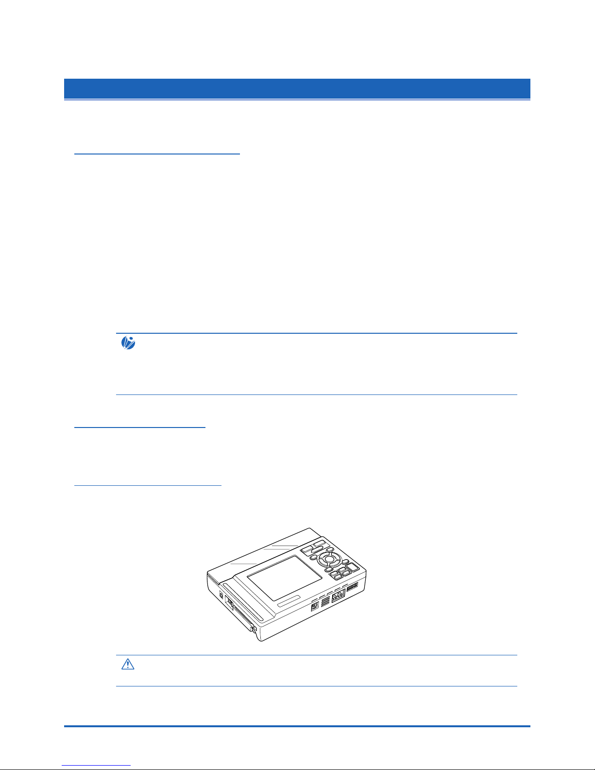
2.3 GL450 Part Names and Functions
This section describes the names and function of parts of the GL450
Monitor
Input terminal 1
Input terminal 2
Screwdriver for mounting
the input terminal unit
Control panel keys
Power connector
Power LED
Data capture LED Battery charging LED
Power switch
USB connector terminal
LAN connector terminal
Monitor control dial
PCMCIA slot
Logic input/
Alarm output terminal
Synchronization
connector terminal
GND
External trigger
Pulse input
Battery
Humidity sensor connector
Top panel
Bottom panel
Power LED........................... This LED is lit when the power switch is in the 'On' status.
Data Capture LED ............... This LED is lit while data is being captured.
Battery Charging LED.......... This LED is lit when the battery is being charged.
Monitor................................. Displays the setting menus and measurement data.
Control panel keys ............... Used for the main operations, including settings, and starting and
stopping measurement.
Power connector.................. Terminal for connecting the AC/DC power cables.
Power switch........................ Switch for turning on the power.
PCMCIA slot ........................ Used for inserting the PCMCIA card.
Logic input/Alarm output terminal
................................... Used for logic input and alarm output.
Synchronization connector terminal
................................... Terminals for connecting and synchronizing additional GL450 units
(used with the functions in OPS022).
GND terminal ....................... Connects the main unit to ground.
Pulse input........................... Terminal for the measurement of pulse signals.
External trigger .................... Terminal for the input of external triggers.
Input terminal 1 & 2.............. Used to connect the 10-, 20-, and 50-ch input terminal units.
USB connector terminal....... Terminal for connecting the USB cable.
LAN connector terminal ....... Terminal for connecting the LAN cable.
Monitor control dial .............. Used to adjust the monitor contrast.
Humidity sensor connector .. Used to connect the power plug of the B-350 humidity sensor.
Battery ................................. Backup battery used in the case of an AC or DC power failure.
Screwdriver for mounting the input terminal unit
................................... Used to connect the signal input cables to the input terminal unit.
Note: Attach the LCD protector to the surface of the LCD display when you want to protect it.
Page 19
2-4
Checks and Preparation
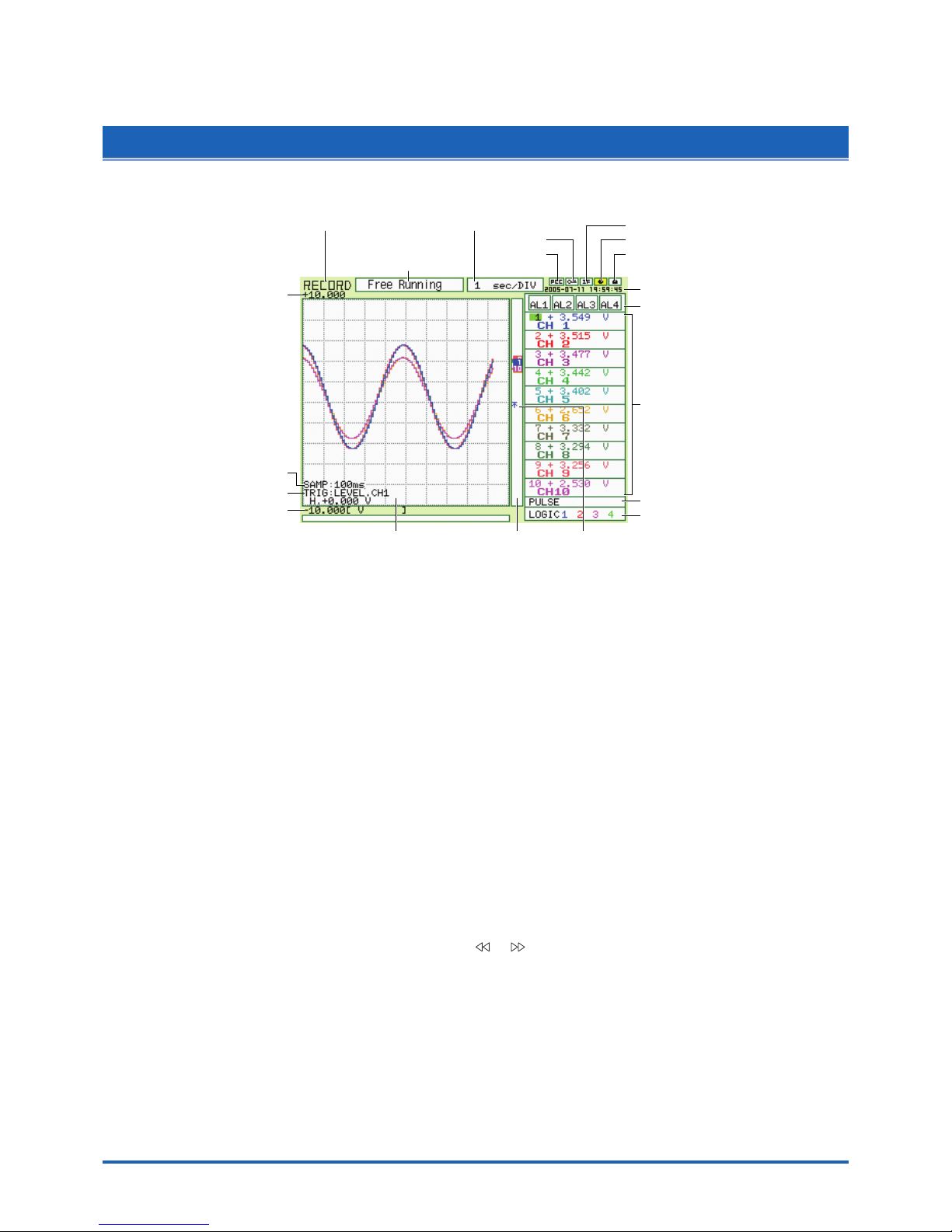
2.4 Monitor Part Names and Functions
This section describes the monitor unit on top of the GL450.
Simplified message
display area
Processing mode display area Time/Div display area
Key lock
PC card
access display
Battery drive
AC drive
Remote
Date/Time display area
Alarm display area
Monitor area
Logic display area
Pulse display area
Waveform/settings window display area
Pen display
Scale upper limit value
Scale lower limit value
Trigger settings
Sampling interval
Level trigger position information
(Left: Start position, Right: Stop position)
Processing mode display area
.................................. Displays the processing mode currently set
Simplified message display area
.................................. Displays the system status. ("Free Running") is usually displayed. For
example, "Armed" is displayed when waiting for a trigger signal.
Time/Div display area ......... Displays the current time scale.
Date/Time display area....... Displays the current date and time.
Monitor area........................ Displays the input signal values for each channel.
Waveform settings/window display area
.................................. Displays the measurement signal waveforms. The menu windows are
also displayed when the condition setting keys are pressed.
Scale upper limit/lower limit
.................................. Displays the measurement scale for the range set.
Sampling interval display .... Displays the specified sampling interval (not displayed during
measurement).
Trigger settings ................... Displays the trigger information.
PC card access display ...... The display flashes while data on the PC card is being accessed.
Key lock .............................. Lit when the GL450 is in key lock status. To enable key lock status,
hold down the [ ] [ ] key for at least three seconds.
Remote ............................... Lit when the GL450 is in remote status
AC drive .............................. Lit when the AC is in use.
Battery drive........................ Lit when the battery is in use.
Pulse display area .............. Displays the measured values.
Logic display area............... Displays the action status.
Pen display ......................... Pens are displayed for each group.
Level trigger position information
.................................. Displays the level position of the Start and Stop triggers (Left: Start
position, Right: Stop position).
Page 20
Checks and Preparation
2-5
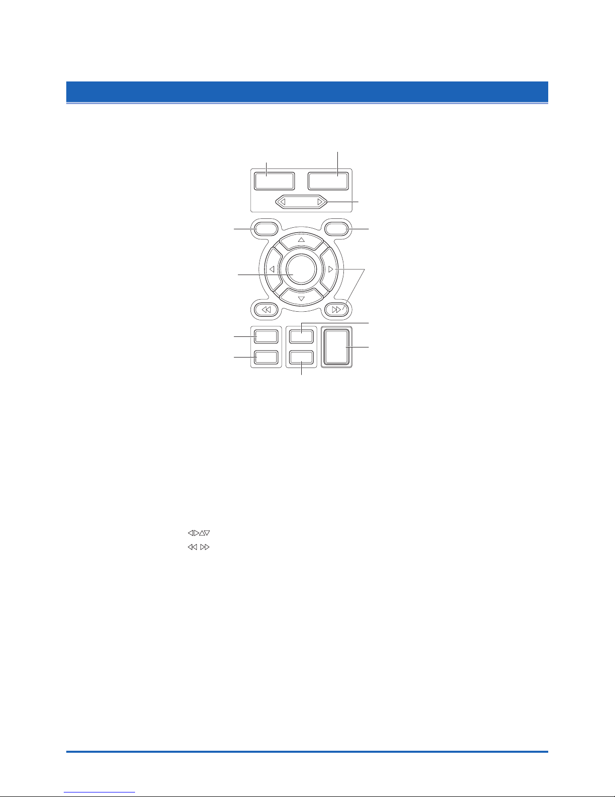
2.5 Control Panel Key Part Names and Functions
This section describes the control panel keys.
CH GROUP
RANGE/SPAN
POSITION
TIME
/
DIV
QUIT
MENU
LOCAL
ENTER
DISPLAY
SAVE
REVIEW
START
STOP
CURSOR
CH GROUP
RANGE/SPAN/POSITION
TIME/DIV
MENUQUIT
DISPLAY
SAVE
START STOP
REVIEW
Direction keys
ENTER
CURSOR
CH GROUP key.................. Switches between channel groups.
RANGE/SPAN/POSITION key
.................................. Switches through the RANGE, SPAN, and POSITION settings on the
monitor display. These settings can be specified for each channel.
Stopped status: INPUT → RANGE → SPAN → POSITION
Replay mode : TRACE → SPAN → POSITION
TIME/DIV key...................... Used to switch the time axes.
QUIT key............................. Used to cancel the displayed setting item. It is also used to cancel the
REMOTE status.
MENU key........................... Switches through the various setting menus.
Direction keys ( ) ....... These keys move the cursor on the screen in the direction indicated.
Direction keys ( ) ....... Press these keys to scroll the memory data waveforms and move the
cursor. Hold down both keys together for at least three seconds to
enable key lock status. To cancel key lock status, press them again for
at least three seconds.
ENTER key ......................... Enters the details set in the current setting window.
DISPLAY key ...................... Switches through the Waveform, Enlarged Waveform, and Digital Data
screens.
REVIEW key ....................... Replays the captured data.
SAVE key ............................ Used to save data and make a copy of the displayed screen.
CURSOR key...................... Used to switch through the Single Cursor, Dual Cursor, and Off
settings.
START/STOP key ............... Press this key to start measurement or to stop measurement when
measurement is in progress.
Page 21

2-6
Checks and Preparation
2.6 Connecting to a PC
The GL450 can be connected to a PC via a LAN cable or a USB cable.
Connection Using a LAN Cable
Use the LAN cable to connect the GL450 to a PC.
LAN cable
Connection Using a USB Cable
Use the USB cable to connect the GL450 to a PC.
USB cable
CHECKPOINT
If the USB cable is used, the USB driver must be installed in your PC. Please refer to Section 4.2
"Installing the USB Driver" for the installation procedure.
Page 22
Checks and Preparation
2-7
2.7
Connecting the Power Cable and Turning on the Power
This section describes how to connect the power cable and turn on the power. The connection method will
vary depending on the type of power supply used.
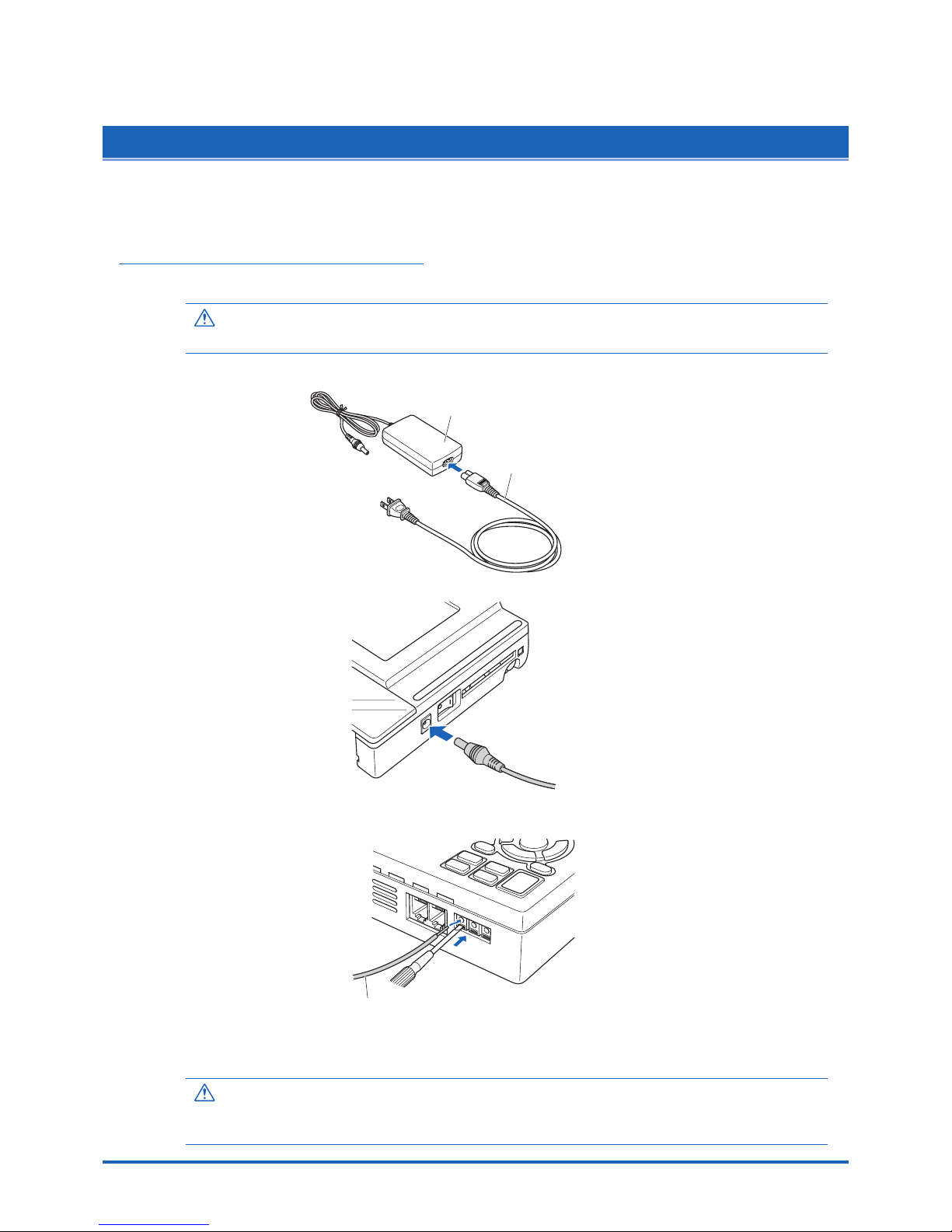
Connecting to an AC Power Supply
Use the AC cable and AC adapter that are provided as accessories.
CAUTION
Be sure to use the AC adapter that is supplied as a standard accessory.
(1) Plug the AC cable into the AC adapter.
AC adapter
AC cable
(2) Connect the output side of the AC adapter to the connector on the GL450.
(3) Using the screwdriver provided as a standard accessory, press against the button underneath
the ground terminal while connecting the grounding cable to the GL450. Connect the other end
of the cable to ground.
Grounding cable
(4) Plug the AC cable into the mains power outlet.
(5) Press the power switch on the GL450 to the ON side to turn on the power.
CAUTION
Always connect the GND terminal and refer to the safety precautions. The GL450 must be grounded
even when connected to other devices and sharing a common ground level.
Page 23
2-8
Checks and Preparation
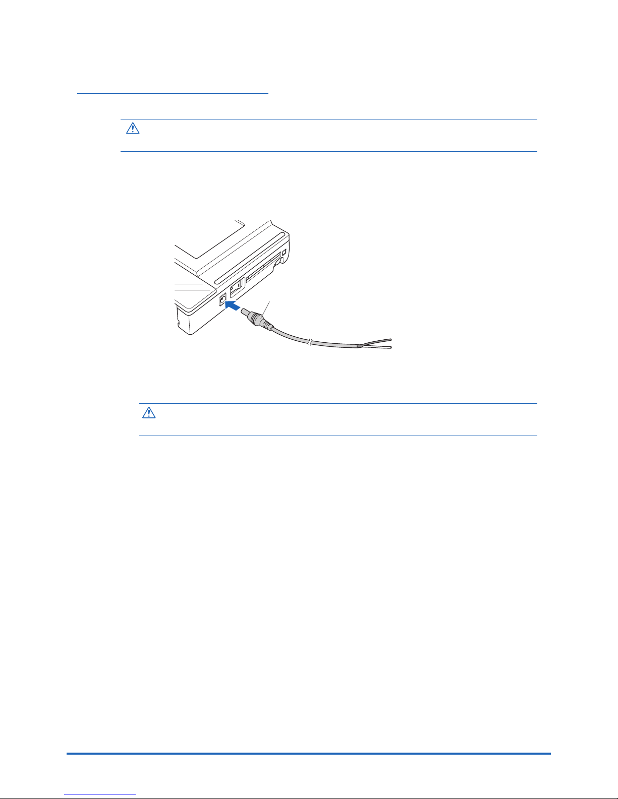
Connecting to a DC Power Supply
Use the optional DC drive cable (B-514).
CAUTION
Use a power supply within the 8.5 to 24 VDC range.
(1) Configure the tip of the DC drive cable (B-514: 2m) to enable it to be connected to the DC
power supply.
(2) Connect the DC output side to the power supply connector on the GL450.
B-514
8 to 24 VDC power supply
Shielded lead (– side)
White (+ side)
(3) Connect the DC input side to the DC power supply.
CAUTION
Be sure to check the polarity of the wire tips when performing wiring.
(4) Press the power switch on the GL450 to the ON side to turn on the power.
Page 24
Checks and Preparation
2-9
2.8 Using the Battery Pack (Option)
The B-517 battery is the only battery type that can be used with the GL450.
Use the battery pack for data back-up when the AC power supply is interrupted by a power failure or
brownout.
Expected operating time when using the battery pack (fully charged status):
• When the LCD is ON : Approx. 2 hours
• When the LCD is OFF: Approx. 3 hours
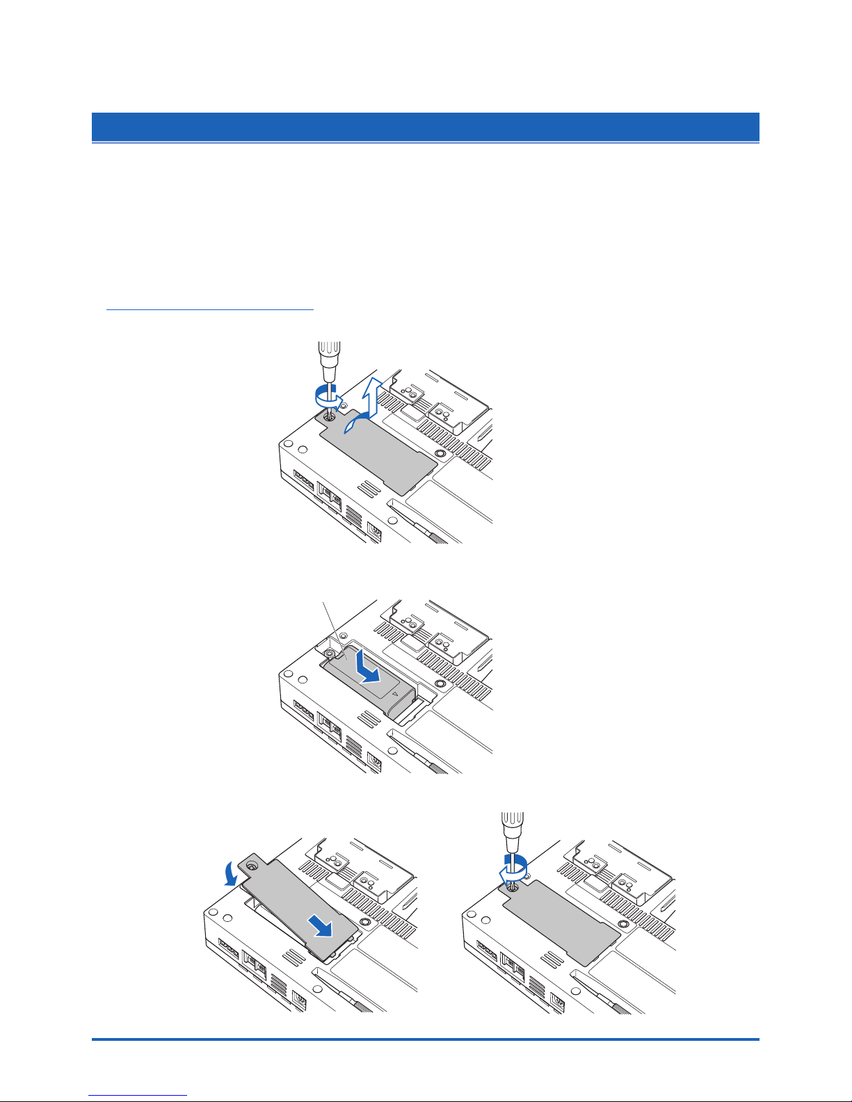
Mounting the Battery Pack
(1) Use a screwdriver to remove the battery pack cover from the bottom panel.
(2) Mount the battery pack in the direction shown by the arrow.
Battery pack
(3) Reattach the cover, and fasten the screw in place.
Page 25

2-10
Checks and Preparation
Charging the Battery
Expected time required for charging:
• Approx. 4 hours
Using the GL450 for Charging
The battery pack is charged by mounting it in the GL450, and supplying it with AC power.
(1) Mount the battery pack in the GL450 (see the previous section for the mounting procedure).
(2) Turn on the power to the GL450. (Please see Section 2.7, "Connecting the Power Cable and
Turning on the Power").
(3) The battery charging LED lights.
Power LED
Battery charging LED
CHECKPOINT
• If battery charging is attempted immediately after the GL450 has been used continuously, charging
may not be performed. However, charging will start automatically as soon as the GL450 has cooled
down.
Charging temperature: 15 to 35°C
• If input is being made directly from the DC power supply instead of the AC adapter, the DC voltage
must be at least 16V.
Page 26

Checks and Preparation
2-11
2.9 Inserting and Removing a PCMCIA Card
This section describes how to insert a PCMCIA card.
CAUTION
Adequate precautions against static electricity must be taken when handling PCMCIA cards.
Inserting a PCMCIA Card
Insert the PCMCIA card into the slot as far as it will go.
Removing a PCMCIA Card
Press the eject button next to the PCMCIA card slot so that the button protrudes. Press it once
more to eject the PCMCIA card.
Press
Press
once more
Page 27

2-12
Checks and Preparation
2.10 Mounting and Removing the Input Terminal Unit
This section describes how to mount and remove the input terminal unit.
CAUTION
Make sure that the power supply has been turned off before mounting or removing the input terminal unit.
Mounting the Input Terminal Unit
(1) Remove the cover from the input terminal mounting area.
(2) As shown in the figure below, insert the input terminal unit in the GL450. At this time, be sure
to check that the terminal unit is locked onto the connector.
Removing the Input Terminal Unit
(1) Remove the cover from the input terminal mounting area.
(2) Press down on the lock button while pulling the input terminal unit towards you. At this time,
grip the input terminal unit firmly while removing it.
(3) Replace the cover for the input terminal mounting area.
Page 28

Checks and Preparation
2-13
2.11
Connecting the Signal Input Cables to the Input Terminal Unit
This section describes how to connect the signal input cables to the input terminal unit.
Input Terminal Unit Types
There are three types of input terminal unit:
• 10-channel input terminal unit (mounted in the GL450) : 10TU
• 20-channel input terminal unit (mounted in the GL450) : 20TU
• 50-channel input terminal unit (used outside the GL450): 50TU
Note: Each of these input terminal units has been designed for use with the GL450 model only.
CHECKPOINT
These input terminal units are for use with the GL450 model only. Moreover, input terminal units
designed for other models cannot be used with the GL450.
Terminal Configuration and Signal Types
Terminal layout on the top part of the unit
Terminal 1 Terminal 2
CH6 CH7 CH8 CH9 CH10
CH1 CH2 CH3 CH4 CH5
CH6 CH7 CH8 CH9 CH10
CH1 CH2 CH3 CH4 CH5
+
– b
Terminal configuration
+
–
Voltage
++
––
Thermocouple
+
– b
Resistance
temperature
detector (RTD)
Current
measurement
Signal source
For current in the 4 to 20 mA range,
apply a resistance of 250 Ω and
perform measurement in the 1-5V
range.
+ ......................................... High-voltage terminal (terminal for high-voltage input signals)
–.......................................... Low-voltage terminal (terminal for low-voltage input signals)
b.......................................... Terminal used for RTDs only
Item Description
Input configuration Isolated input, scanning
Analog voltage 20, 50, 100, 200, 500 mV/F.S.; 1, 2, 5, 10, 20, 50 V/F.S.; 1-5V
Thermocouples K, J, E, T, R, S, B, N, W (WRe 5-26)
Resistance Temperature Detector Pt100, JPt100
Sampling interval*
1
100, 200, 500 ms; 1, 2, 5, 10, 20, 30 s; 1, 2, 5, 10, 20, 30 min; 1 h
A/D resolution 16-bit
Filter On, Off (software filter)
*1 The maximum sampling interval will depend on the number of channels being used.
Page 29

2-14
Checks and Preparation
Attaching the Input Cable
(1) Use the supplied screwdriver to loosen the terminal screw.
(2) Insert the cable tips into the terminal to be used.
(3) Use the supplied screwdriver to tighten the terminal screw.
Page 30

Checks and Preparation
2-15
2.12
Precautions to Observe When Performing Measurement
Please be sure to read the following carefully in order to prevent electric shocks or shorts.
DANGER
• Do not input voltages exceeding 30 VAC rms or 60 VDC to any of the individual analog input sections or
between the analog input section and the main unit.
• Be sure to use only the AC adapter provided as a standard accessory. The rated power supply range for the
adapter is 100 to 240 VAC, and the rated frequency is 50/60 Hz. Do not use any other voltages.
Input Circuit Diagram for Analog Input (Voltage, Thermocouples)
50Ω
50Ω
500kΩ
500kΩ
0.05µF
0.05µF
Channel Switching Relay
+
–
CAUTION
Capacitors have been incorporated into the input circuit to increase the noise elimination capability.
After voltage measurement, when the inputs have been disconnected, there will still be some electric
charge remaining. Before starting another measurement operation, short-circuit the + and - terminals to
enable self-discharge.
Page 31

2-16
Checks and Preparation
2.13 Noise Countermeasures
Be sure to connect the chassis GND of the object to be measured.
Ensure that the chassis GND wire of the measurement object is connected to a good ground.
Measurement object
Z
3
GL450
Z1Z
2
+
–
Vin
R1
R2
Input terminals
Thermocouple
Connect the signal chassis GND and the measurement device chassis ground.
Use a short, thick lead to connect the chassis GND of the measurement object to the GL450's
chassis GND. It will be even more effective if the ground potentials are the same.
Measurement device chassis GL450
GND GND
GND PULSE EXT
TRIG
Page 32

Checks and Preparation
2-17
2.14 Logic/Alarm Functions
Connect the round connector of the logic alarm cable (B-513, option) to the logic Input/alarm output terminal
on the GL450.
Logic alarm cable
(B-513: 2m)
Logic Functions
Alarm Functions
Alarm Output Circuit
Note: Be sure to not to exceed the maximum ratings
Maximum rating
VCEO (voltage between connector and emitter): 30V
IC (connector current): 0.5A
+5V
100K
GL450
Wiring
The cables have bare tips. Please perform wiring as required.
Item Description
Number of channels 4
Input voltage range 0 to +24V max. (single-ended ground input)
Threshold level +2.5V
Hysteresis Approx. 1 V (+2 to +3 V)
Item Description
Number of channels 4
Maximum rating VCEO (voltage between connector and emitter): 30V
IC (connector current): 0.5A
Item Number Lead Color
Logic signal 1 Orange/red
2 Orange/black
3 Gray/red
4 Gray/black
Alarm output 1 White/red
2 White/black
3Yellow/red
4Yellow/black
Common ground GND Pink
GND Pink
GND Shielded lead
Orange/red
Orange/black
Logic signals
Gray/red
Gray/black
White/red
White/black
Alarm output
Yell ow/red
Yell ow/black
Pink
Pink
GND
Shielded lead
Logic alarm cable (B-513)
Page 33

2-18
Checks and Preparation
2.15 Trigger/Pulse Functions
External Trigger Functions
GND PULSE EXT
TRIG
Pulse Functions
GND PULSE EXT
TRIG
Item Description
Number of channels 1
Input voltage range 0 to +24V max. (single-ended ground input)
Threshold level +2.5V
Hysteresis Approx. 0.5 V (+2.5 to +3 V)
Item Description
Number of channels 1
Input voltage range 0 to +24V max. (single-ended ground input)
Threshold level +2.5V
Hysteresis Approx. 0.5 V (+2.5 to +3 V)
Page 34

Checks and Preparation
2-19
2.16 Connecting the Humidity Sensor
Connect the + and - lead wires of the humidity sensor (the B-530 option) to the desired terminals, and then
insert the round connector into the 5V OUT connector on the GL450.
Round connector
+, – lead wires
Humidity sensor
Page 35

2-20
Checks and Preparation
2.17
Setting the Date and Time
If you are using the GL450 for the first time, charge the internal rechargeable battery and then make the date
and time settings.
CAUTION
If the GL450 is not used for a period of approximately three months, the internal rechargeable battery may be
discharged and the date and time may revert to the initial settings. If this happens, recharge the battery before
using the GL450.
How to Recharge the Rechargeable Battery
Using the AC adapter provided, connect the GL450 to a mains power outlet, turn on the power switch, and then
leave the GL450 connected for at least 24 hours.
How to Set the Date and Time
Press the [MENU] key, display the "OTHR" screen, and then set the date and time at the Date/Time
Settings sub-menu. For details, see "Date/Time" on page 3-26.
Page 36

This chapter describes the setting and
measurement procedures for the GL450.
CHAPTER
3
Settings and Measurement
3.1 Basic Settings and Measurement
3.2 Detailed Settings and Measurement
3.3 Data Replay
Page 37

3-2
Settings and Measurement
3.1 Basic Settings and Measurement
With the GL450, control panel keys are provided for easy measurement.
CH GROUP
RANGE/SPAN
POSITION
TIME
/
DIV
QUIT
MENU
LOCAL
ENTER
DISPLAY
SAVE
REVIEW
START
STOP
CURSOR
(3) TIME/DIV key
(2) RANGE/SPAN/POSITION key(1) CH GROUP key
(4) START STOP key
(6) DISPLAY key
(8) SAVE key
(7) REVIEW key
(5) Direction keys
(9) CURSOR key
(1) CH GROUP key
This key selects the channels in 10-channel groups. Press the key to move to the next group of 10
channels. The number of channels varies according to the type of input terminal unit installed.
1 to 10 11 to 20 81 to 90 91 to 100
Waveform + digital Digital
Page 38

Settings and Measurement
3-3
(2) RANGE/SPAN/POSITION key
These settings can be made or changed for each channel individually, even while the GL450 is
running or performing measurement.
CHECKPOINT
The monitor is used for monitoring the measurement status only, and its settings cannot be changed. In
addition, the RANGE setting can only be changed if data has not been captured.
Selecting the Items
Press the RANGE/SPAN/POSITION key to switch from one setting screen to the next.
Waveform + Digital
(for monitoring
measurement only)
(only when data
has not been captured)
(only when data
has not been captured)
INPUT RANGE SPAN POSITION
Waveform + Digital INPUT RANGE settings SPAN settings
POSITION settings
Setting Procedure
Use the direction keys to move to the setting item and to make selections (settings).
QUIT MENU
LOCAL
ENTER
CH settings
Select (set)
INPUT settings
OFF, Voltage, Temperature, Humidity
RANGE settings
The voltage and temperature settings vary according to the settings made in MENU (AMP).
• Voltage
20 • 50 • 100 • 200 • 500 mV • 1 • 2 • 5 • 10 • 20 • 50 • 1–5 V
• Temperature
TC-K • TC-J • TC-T • TC-R • TC-E • TC-B • TC-S • TC-N • TC-W • Pt100 • JPt100
Page 39

3-4
Settings and Measurement
SPAN settings
*1 When 1-5V has been specified and the range is changed, it becomes a ± range. If the 1-5V range is required,
please select 1-5V for the range setting once again.
*2 With the temperature ranges, the measurement range will depend on the type of sensors used. If you want to
make detailed settings, please set the range again.
POSITION settings
If the ENTER key is pressed when POSITION has been selected, the position can be moved.
Voltage ranges: In 10% units of the range
Temperature ranges: In 10% units of the following ranges:
50.0, 100.0, 200.0, 500.0, 1000.0, 2000.0
(3) TIME/DIV key
Press the TIME/DIV key to switch through the waveform display speeds.
1 • 2 • 5 • 10 • 20 • 30 • 1 • 2 • 5 • 10 • 20 • 30 • 1 • 2 • 5 • 10 • 12 • 24
sec/DIV min/DIV
hour/DIV
TIME/DIV display
(4) START/STOP key
Press the START/STOP key to select the START status (Armed). Press it once again to select the
STOP status (Free Running).
20 mV 0.200 to 40.000 mV/F.S. 2 V 0.0200v4.000 V/F.S.
50 mV 0.50 to 100.00 mV/F.S. 5 V 0.050 to 10.000 V/F.S.
100 mV 1.00 to 200.00 mV/F.S. 10 V 0.100 to 20.000 V/F.S.
200 mV 2.00 to 400.0 mV/F.S. 20 V 0.200 to 40.000 V/F.S.
500 mV 5.0 to 1000.0 mV/F.S. 50 V 0.50 to 100.00 V/F.S.
1 V 0.0100 to 2.0000 V/F.S. 1-5 V*
1
0.040 to 4.000 V/F.S.
Temperature*
2
50.0 to 2200.0 °C/F.S.
Voltage
Page 40

Settings and Measurement
3-5
(5) Direction keys
Direction keys ( ) ....... These keys move the cursor on the screen in the direction indicated.
Direction keys ( ) ........... Press these keys to scroll the memory data waveforms, move the
cursor, and specify the position of input values on menu screens.
Direction keys ( ) ....... Press these keys to scroll the memory data waveforms, move the
cursor, to move the position during key lock status and for text
settings.
(6) DISPLAY key
Press this key to switch through the measurement modes: Waveform/Digital, Waveform,
Calculation, Digital, and the RECORDER display screens.
Waveform + Digital
Waveform Calculation Digital
Waveform + Digital Waveform DigitalCalculation
Waveform + Digital Screen: Both waveform and digital data are displayed together.
Waveform Screen : Only waveforms are displayed over the entire screen.
Calculation Display Screen: Digital data and the calculation results are displayed.
Digital Screen : The digital values for four channels are displayed.
(7) REVIEW key
Press the REVIEW key during measurement for a dual-screen display of past data alongside the
current data.
Current dataPast data
If the REVIEW key is pressed during the Free Running status (when data is not being captured),
the captured data is replayed.
Page 41

3-6
Settings and Measurement
(8) SAVE key
Press the SAVE key to save data (the data being replayed), and to make a copy of the screen.
Data Save: When a file name is selected, the data save destination is displayed, and the data can
be saved by specifying the following parameters:
• File format : GBD, CSV
• File name append method: Auto (Specify folder name), User (specify file name)
BMP Copy: When a file name is selected, the bitmap save destination is displayed, and the
displayed screen can be saved in bitmap format by specifying the following parameter:
• File name append method: Auto (Specify folder name), User (specify file name)
Save Data Between Cursors (during data replay only):
When captured data is replayed, the data between cursors can be saved by specifying
the following parameters:
• File format: GBD, CSV
• File name append method: Auto (Specify folder name), User (specify file name)
CAUTION
Data can only be saved when there is a PCMCIA card inserted in the card slot.
Data saved to the internal memory will be deleted when the GL450 is turned off.
(9) CURSOR key
When the REVIEW key has been pressed and the replayed data is displayed, the cursor key can
be used to select three cursor modes.
Cursor A Cursor B
A: 1 cursor is moved.
B: 1 cursor is moved.
Page 42

Settings and Measurement
3-7
3.2 Detailed Settings and Measurement
The QUIT and MENU keys enable detailed settings to be made.
CH GROUP
RANGE/SPAN
POSITION
TIME
/
DIV
QUIT
MENU
LOCAL
ENTER
DISPLAY
SAVE
REVIEW
START
STOP
CURSOR
(2) MENU key(1) QUIT key
(1) QUIT key
Use the [QUIT] key for operations such as the ones described below.
• To switch from a menu screen to a measurement screen.
• To close the selected screen.
• To exit the captured data replay screen.
• To perform quit operations as instructed by messages displayed in the menus.
Page 43

3-8
Settings and Measurement
(2) MENU key
Press the MENU key to switch through the AMP, ANNO, DATA, ALM, FILE, I/F, OTHR and INFO
setting menus. It can also be used to confirm details.
AMP ANNO DATA ALM FILE I/F OTHR INFO
qwertyui
qq
qq
q AMP Settings Window
AMP Menu Structure
Setting Selections available Setting method
Input Off, Voltage, Temperature, Humidity ENTER→Select→ENTER
Humidity: (CAUTION: The voltage is compulsorily set to
1V, and the scaling function set to ON.
Range Voltage: 20, 50, 100, 200, 500 mV ENTER→Select→ENTER
1, 2, 5, 10, 20, 50, 1-5 V
Temperature: TC-K, TC-J, TC-T, TC-R, TC-E, TC-B,
TC-S, TC-N, TC-W, Pt100, JPt100
Filter Off, On ENTER→Select→ENTER
Function(EU) Off, On (effective when On has been selected) ENTER→Select→ENTER
Lower Setting – Settings
Value – Upper • Meas. Value (Upper/Lower)
ENTER→Set numeric value→ENTER
Unit • EU Value (Upper/Lower)
ENTER→Set numeric value→ENTER
• Dec pt ENTER→Select→ENTER
• Unit ENTER→Select→ENTER
• Select ENTER→Select→ENTER
Register ENTER
Color Current Color, Sel Color ENTER→Select→Register
Misc. Zero voltage adjustment Press ENTER to execute
• Perform Auto Zero ADJ.
• Reset Auto Zero ADJ.
[Zero point voltage value]
Misc
(only when ALL
Span All Settings ENTER→Set numeric value→
has been selected)
• Upper/Lower ENTER→Execute
Mode OFF, Revol., Counts, Inst. ENTER→Select→Register
Range Revol.: 500, 5k, 50k, 500k RPM/F.S. ENTER→Select→ENTER
Counts: 50k, 500k, 5M, 50M, 500M C/F.S.
Inst.: 50k, 500k, 5M, 50M C/F.S.
EU Function: Off, On ENTER→Select→ENTER
• Scaling settings ENTER→Select→Register
• Setting values (Use direction keys to select
• Unit settings numeric value)
• Unit
Slope H, L ENTER→Select→ENTER
Logic Off, On ENTER→Select→ENTER
Color specification
Specified color ENTER→Select→Register
EU (Scaling settings)
Pulse
Logic
Page 44

Settings and Measurement
3-9
CHECKPOINT
When the CH setting is ALL, the Input, Range and Filter settings are the same for all the channels in
that group.
Input.................................... Selects the input condition.
Off: No signal input is accepted.
Voltage: Used for measuring direct-current voltage.
Temperature:Used for measuring temperature.
Humidity: Used for measuring humidity.
Range ................................. Specifies the range of signal input to be measured.
Voltage: 20, 50, 100, 200, 500 mV
1, 2, 5, 10, 20, 50, 1-5 V
Temperature:TC-K, TC-J, TC-T, TC-R, TC-E, TC-B, TC-S, TC-N,
TC-W, Pt100, JPt100
Available SPAN Settings
<Voltage Ranges>
<Temperature Ranges>
<Humidity Range>
Fixed to 1V
Filter.................................... Sets the filter status. Please set the filter to ON when there is likely to
be noise in the input.
Off, On
EU....................................... Scales the measured values and converts them to other units.
Function (EU): Sets the EU function to Off or On.
Maximum SPAN Minimum SPAN
Range Lower to Upper SPAN Lower to Upper SPAN Upper SPAN minus
[mV] [V] Lower SPAN
1 –1.1000 to +1.1000 10 mV
2 –2.2000 to +2.2000 20 mV
5 –5.500 to +5.500 50 mV
10 –11.000 to +11.000 100 mV
20 –22.000 to +22.000 –22.000 to +22.000 0.2 mV 200 mV
50 –55.00 to +55.00 –55.00 to +55.00 0.5 mV 500 mV
100 –110.00 to +110.00 1.0 mV
200 –220.00 to +220.00 2.0 mV
500 –550.0 to +550.0 5.0 mV
Range
Maximum SPAN Minimum SPAN
Lower to Upper SPAN
Upper SPAN minus Lower SPAN
K -200.0 to +1370.0 50°C
J -200.0 to +1100.0 50°C
T -200.0 to +400.0 50°C
R 0.0 to +1600.0 50°C
E -200.0 to +800.0 50°C
B 600.0 to +1820.0 50°C
S 0.0 to +1760.0 50°C
N 0.0 to +1300.0 50°C
W 0.0 to +2315.0 50°C
PT100 -200.0 to +850.0 50°C
JPT100 -200.0 to +500.0 50°C
Page 45

3-10
Settings and Measurement
Lower - EU - Upper Unit:
Sets the EU function's conversion value and unit. If the ENTER key is
pressed here, the following window is displayed.
(e) Select
(a) Meas. Value (b) EU Value
(f) Choose
(c) Dec pt
(d) Unit
CHECKPOINT
The Scaling operation is calculated using a ratio of the Meas. Value or
EU Output Value settings. If a ratio value that the GL450 cannot
process is specified, the message below appears.
Out of input range
[ENTER] Apply
If this message appears, follow the instructions by reducing the
number of digits to be output by one, or leaving the number of digits
as is and changing the EU value.
(a) Meas. Value
Specifies the numeric value to be converted. Set two points, the
Upper and Lower parameters.
(b) EU Value
Specifies output after conversion. Set two points, the Upper and
Lower parameters.
(c) Dec pt
This parameter specifies the decimal point position of the numeral
to be specified as the EU value(s).
(d) Unit
Selects the converted unit, which can be specified as a userdefined character string consisting of alphanumerics. The Unit
parameter can also be specified by selecting the Select Unit
setting.
(e) Select
Selects the type of engineering unit.
(f) Choose
Selects the converted unit. The Unit displayed here is the type of
unit selected by the Select setting.
To specify a unit that is not displayed here, specify a user-defined
character string as the Unit setting. Moreover, the setting specified
here is displayed as the Unit setting.
Upper Value Lower Value
+2.5000 –2.5000
+10.000
Specified Value
EU Value –10.000
+5 V
CH.1 10V
–5 V
+20.00 rpm
CH.1 Scaling 1
–20.00 rpm
Setting Example
Page 46

Settings and Measurement
3-11
Color ................................... This parameter enables the automatically set value for each channel
to be changed manually.
Misc. ................................... For voltage settings, zero position adjustment can be performed
automatically, and the zero position reset.
Perform Auto Zero ADJ.:
Moves the current 'pen' position to the origin point.
Reset Auto Zero ADJ.:
The zero position voltage value resets the displayed voltage value
and adjusts the 'pen' to the origin point.
Misc. (ALL).......................... When ALL has been selected, the Misc. menu contains a “Span All
Settings” function that enables all the SPAN settings for the same
group to be set simultaneously to the same values.
Upper, Lower:
Input the required values on the displayed setting screen.
Page 47

3-12
Settings and Measurement
Pulse................................... The signals that can be input to the pulse input terminal for data
processing are Revol., Counts, and Inst.
Modes: Select from OFF, Revol., Counts, and Inst.
• Off: Input is disabled.
• Revol.: Counts the number of pulses per second, and displays the
values multiplied by 60 as rpm values.
• Counts:Displays the cumulative number of pulses for each
sampling interval from the start of measurement.
• Inst.: Displays the number of pulses for each sampling interval.
Range: Can be set for each of the modes.
EU: Scales and converts the measured value.
• Meas. Value:Specifies the numeric value to be converted.
• EU Value: Specifies output after conversion.
• Unit: Selects the converted unit, which can be specified as
a user-defined character string consisting of
alphanumerics. The Unit parameter can also be
specified by selecting the Select Unit setting.
• Select: Selects the type of engineering unit.
• Choose: Selects the converted unit. The Unit displayed here is
the type of unit selected by the Select Unit setting.
Slope: Sets the condition for the input signal operation.
• H: Operates when the signal is a rising signal
• L: Operates when the signal is a falling signal.
Logic ................................... Enables logic amps to be used: Off (disabled), On (enabled).
Color specification for each channel:
This parameter enables the automatically set value for each channel
to be changed manually.
Mode Range Maximum number
of pulse inputs
Revol. 500, 5k, 50k, 500k Revol./F.S. 50k/s
Counts 50k, 500k, 5M, 50M, 500M C/F.S. 50k/sampling interval
Inst. 50k, 500k, 5M, 50M C/F.S. 50k/sampling interval
Page 48

Settings and Measurement
3-13
ww
ww
w ANNO Settings Window
Annotation settings can be made for each channel.
ANNO Menu Structure
Input procedure
• Up to 11 characters can be input for each channel.
• Text, numerals, and symbols can all be used.
• Display legend
A:Select to input upper-case text
a:Select to input Lower-case text
0:Select to input Numerals
+:Select to input symbols
← : Select to move the cursor to the left to delete text. The selected character is deleted.
↓ : Select to move the cursor to the position where you want to input text. Text is input at the
selected character.
OK : Select to save the input text.
CAUTION
If [ * * ] displayed on the screen, this indicates that text from the OPS022 software has been input in a
format that cannot be displayed on the GL450 monitor.
Setting Selections available Setting method
Annotation character string Alphanumerics, symbols ENTER→Select→OK
Page 49

3-14
Settings and Measurement
ee
ee
e DATA Settings Window
Data capture, Data replay, and Statistical Calculation settings are made here.
DATA Menu Structure
Record Settings
Detailed settings for data capture are performed in this section.
Sampling Interval ................ Specifies the sampling interval for data capture. 16 intervals are
provided.
CHECKPOINT
The maximum sampling interval that can be selected depends on the
number of channels.
• 10ch: 100 ms • 30/40/50 ch: 500ms
• 20ch: 200 ms • 60ch or more: 1 sec
Capture Destination ............ Selects the destination for saving measured data.
Memory: 4 Mbytes (2 Mwords)
This is the total amount of memory . If the number of
channels used is increased, the amount of data that
can be captured is reduced.
Setting Selections available Setting method
Record Settings
100, 200, 500ms 1, 2, 5, 10, 20, 30s ENTER→Select→ENTER
• Sampling Interval 1, 2, 5, 10, 20, 30min, 1h
Capture Destination Memory, PC Card ENTER→Select→ENTER
File Name Specify file (only when PC card has been selected)
• File Type: GBD, CSV ENTER→Select→ENTER
• Name Type: Auto, User ENTER→Select→ENTER
• File: Folder name, file name ENTER→Specify file→OK
Auto Save Off, I hour, 3 hours, 6 hours, 12 hours, 24 hours ENTER→Select→ENTER
(only when internal memory has been selected)
Statistical Calculation
Off, Average, Max, Min, Peak, RMS ENTER→Select→ENTER
• Function
Calculation channel Select the number of channels from the input terminal unit: ENTER→Select→ENTER
specification
2 ch
Page 50

Settings and Measurement
3-15
PC Card:Commercially-available PCMCIA cards can be used in the
PC slot. The amount of data that can be saved to the card is
determined by the card itself. (Please see Specifications for
the types of card that can be used.)
CHECKPOINT
When the captured data is Binary data, the reference to use is 1 data =
2 bytes. Accordingly, if the memory is 12 bytes, approximately 6
Mwords of data can be captured. However, since there is also some
auxiliary data, data larger than this reference figure will be captured. In
addition, when the Excel data format is used, the data will increase to
7-8 times in size. The data capture time will be shorter than that for
Binary data.
File Name ........................... This parameter is displayed when PC card is selected as the capture
destination.
File Type: This sets the file format for the data to be saved.
• GBD: Binary format
• CSV: Excel format
Name Type: Either Auto or User can be selected.
Folder: The currently selected folder is displayed. Settings cannot be
made here.
File name (User): A new folder and a new file are created here.
Capture Time...................... The time is automatically calculated, based on the sampling interval
and the data capture volume, and displayed. This item is displayed
only, and cannot be specified.
Page 51

3-16
Settings and Measurement
Auto Save ........................... When this parameter has been selected, a file is created for each data
capture time.
Off, 1, 3, 6, 12, 24 hours
The maximum data capture time that can be selected depends on the
sampling interval.
• 24 hours: 1s or less sampling interval
• 12 hours: 500 ms or less sampling interval
• 6 hours: 200 ms or less sampling interval
• 3 hours: 100 ms or less sampling interval
If the allowable data capture time is exceeded, the actual data capture
time will be shortened.
Statistical Calculation
Statistical calculation is performed on the replay data between the cursors.
Function .............................. There are five types of between-cursor calculation functions, and four
of these can be selected.
Off: Calculation is not performed.
Average: The simple average value of the data between the cursors is
displayed.
Max: The maximum value of the data between the cursors is
displayed.
Min: The minimum value of the data between the cursors is
displayed.
Peak: The peak value of the data between the cursors is displayed.
RMS: The effective value of the data between the cursors is
displayed.
R.M.S = ΣD2/n
D: data n: number of data
Channel specification: Specifies the two channels "A" and "B" for
calculation.
CHECKPOINT
Calculation results during data capture are displayed on the Calculation
Display screen.
Page 52

Settings and Measurement
3-17
rr
rr
r ALM Settings Window
The Alarm and Trigger settings are made here.
Combination
Determines the alarm output conditions. The logic alarm cable (B-513, option) is required for alarm
output.
OR: Outputs an alarm when each alarm condition is met.
AND:Outputs an alarm when all of the alarm conditions are met.
Repeat Trigger
Used to specify repeated measurement. Measurement is performed repeatedly according to the
Trigger Start and Stop conditions until the START/STOP key is pressed.
On: Repeated measurement
Off: Single measurement operation
CHECKPOINT
If repeated measurement has been specified and Memory selected as the capture destination, data
captured to the GL450's internal memory is overwritten.
Setting Selections available Setting method
Combination OR, AND ENTER→Select→ENTER
Repeat Trigger On, Off ENTER→Select→ENTER
Mode H, L, Win In, Win Out ENTER→Select→ENTER
Lower - Level - Upper Numeric settings ENTER→Select→ENTER
Output 1 to 4 ENTER→Select→ENTER
Pulse
• Mode L, H, Win In, Win Out ENTER→Select→ENTER
•
Lower - Level - Upper
Numeric settings ENTER→Select→ENTER
• Output 1 to 4 ENTER→Select→ENTER
Logic
• Mode X, L, H ENTER→Select→ENTER
• Output 1 to 4 ENTER→Select→ENTER
Trigger
• Start Off, Level, Alarm, Ext., Specified Time ENTER→Select→ENTER
Alarm output selection: 1 to 4 ENTER→Select→ENTER
• Stop Off, Level, Alarm, Ext., Time, Specified Time ENTER→Select→ENTER
Alarm output selection: 1 to 4 ENTER→Select→ENTER
Time setting: 1 s to 9999 h ENTER→Select→ENTER
Page 53

3-18
Settings and Measurement
Condition settings
Mode................................... Determines the alarm output condition
Off: The alarm function is disabled.
Rising:An alarm is generated when the signal input rises to (or
exceeds) the specified alarm level.
CH.1
Alarm generated
Falling: An alarm is generated when the signal input falls to (or falls
below) the specified alarm level.
CH.1
Alarm generated
Win In: Specifies the upper and lower alarm limits for each channel.
When the signal level goes within (or is within) both limits, an
alarm is generated.
CH.1
Alarm generated
Win Out: Specifies the upper and lower alarm limits for each channel.
When the signal level goes outside (or is outside) both limits,
an alarm is generated.
CH.1
Alarm generated
Lower - Level- Upper .......... Specifies the alarm level(s) for the conditions set in Mode.
Rising, Falling: Input a numeric value.
Win In, Win Out: Input numeric values for the upper and lower levels.
Output ................................. Specifies the output channels for alarm generation (4 channels).
Page 54

Settings and Measurement
3-19
Pulse
Sets the alarms for pulse input settings. These conditions can be set when they have been enabled
in the AMP settings.
Mode................................... Sets the same conditions as for "Condition Settings". Please refer to
"Condition Settings" in the previous section.
Lower - Level- Upper .......... Specifies the alarm level(s) for the conditions set in Mode.
Rising, Falling: Input a numeric value
Win In, Win Out: Input numeric values for the upper and lower levels.
Output................................. Specifies the output channels for alarm generation (4 channels).
Logic
Sets the alarms for logic input settings. These conditions can be set when they have been enabled
in the AMP settings.
Mode................................... Sets the logic alarm conditions.
X: No alarm conditions set.
L: Enabled when the logic signal goes from High to Low.
H: Enabled when the logic signal goes from Low to High.
Trigger Settings
Start .................................... Specifies the trigger condition that must be met in order to initiate
measurement.
Off: No trigger is used. Instead, measurement is initiated by
pressing the START/STOP key.
Level: The start of measurement is triggered when the trigger
condition is satisfied.
Note:The Level condition is the level value set for the specified
channel range set (voltage, temperature).
Alarm: The start of measurement is triggered when the alarm condition
is satisfied.
Ext.: The start of measurement is triggered when a signal is input
from an external trigger terminal.
Specified Time:
Measurement starts at the specified time or when the time
trigger condition is satisfied.
If Repeat Trigger has been specified, the trigger action is as follows:
Triggered at: Off Absolute Time/On Relative Time
Page 55

3-20
Settings and Measurement
Stop .................................... Specifies the trigger condition that must be met in order to stop
measurement.
Off: No trigger is used. Instead, measurement is stopped by
pressing the START/STOP key.
Level: Measurement is stopped when the trigger condition is satisfied.
Note:The Level condition is the level value set for the specified
channel range set (voltage, temperature).
Alarm: Measurement is stopped when the alarm condition is satisfied.
Ext.: Measurement is stopped when a signal is input from an
external trigger terminal.
Time: Sets the amount of time from the start until the end of measurement.
The time can be specified from 1 second to 9999 hours.
Specified Time:
Measurement is stopped (data capture ends) at the specified time or
when the time trigger condition is satisfied.
If Repeat Trigger has been specified, the trigger action is as follows:
Triggered at: Off Absolute T ime/On Relative Time
Page 56

Settings and Measurement
3-21
tt
tt
t FILE Settings Window
Saves or loads the PCMCIA card settings or returns them to their factory default settings.
Save current settings .......... Saves the currently selected settings. When this setting is selected, a
submenu appears for selecting the save destination and file name.
Auto: A file name is created using the date and time.
User: The user-specified file name is saved.
Load settings ...................... Loads settings from the PCMCIA card. When this setting is selected, a
submenu appears for specifying the source and file name.
File List ............................... Displays a list of the files. When this setting is selected, a submenu
appears for browsing the folders and specifying files.
File Copy............................. Copies the specified file. When this setting is selected, a submenu
appears for specifying the source file and the destination file.
File Rename ....................... Renames the specified file. When this setting is selected, a submenu
appears for selecting the file you wish to rename and its new file
name.
File Delete........................... Deletes the specified file. When this setting is selected, a submenu
appears for selecting the name of the file to be deleted.
Setting Selections available Setting method
Save current settings Auto, User ENTER→Select→ENTER
File name (when User)
• File: Folder name, File name ENTER→Select→EXECUTE
Load settings Select file ENTER→Select→EXECUTE
File List Select file ENTER→Select→EXECUTE
File Copy Select file to load ENTER→Select→EXECUTE
Select file to write
File Rename Select file to convert ENTER→Select→EXECUTE
Converted file name ENTER→Specify file→OK
File Delete Select file ENTER→Select→EXECUTE
Card Initialize Format: Super Floppy, HDD format ENTER→Select→ENTER
Type: Quick, Normal ENTER→Select→ENTER
Volume Label: Specify a volume label ENTER→Specify file→EXECUTE
Page 57

3-22
Settings and Measurement
Card Initialize ...................... Reformats the PCMCIA card.
Format: Select from Super Floppy and HDD-compatible format.
Type: Select Quick Format or Normal Format.
Volume Label:This parameter specifies the volume label of the card to
be reformatted. Specify a volume label of up to 11
characters.
PC Card Info ....................... Displays the volume of data on the PC card. No settings can be made
here.
Page 58

Settings and Measurement
3-23
yy
yy
y I/F Settings Window
The conditions for connecting to your computer are set here.
New Line Code ................... Sets the new line code. Select from CR+LF, LF, or CR.
Echo Back........................... This function can be specified as Enable or Disable.
USB ID Setting.................... Sets the ID number for the GL450. Specify a number from 0 to 7.
TCP-IP Settings .................. Sets the TCP-IP.
IP Address: Sets the IP address.
Subnet Mask: Sets the subnet mask.
Port Number: Sets the port number.
Gateway: Sets a gateway for the network connection.
CHECKPOINT
Be sure to restart the GL450 after settings have been made or changed. If the GL450 is used as is, the
computer connections may not be performed correctly.
USB PC Card Drive Mode
Inserting a PC card in the GL450's card slot and then connecting the GL450 to your computer via
USB enables the GL450 to be used as an external PC card drive.
(1) Insert the PC card in the GL450's card slot.
(2) Use the USB cable to connect the GL450 to your computer.
(3) Turn on the GL450's power supply while holding down the [START] key.
(4) A Removable Disk icon is displayed in your computer's "My Computer" window.
* This operation is recommended only for those computers running Windows 2000 or Windows XP.
* The PC card cannot be replaced when the GL450 is being used as a removable disk.
Setting Selections available Setting method
New Line Code CR+LF, LF, CR ENTER→Select→ENTER
Echo Back Enable, Disable ENTER→Select→ENTER
USB ID 0 to 7 ENTER→Select→ENTER
IP Address Numeric setting ENTER→Select→ENTER
Subnet Mask Numeric setting ENTER→Select→ENTER
Port Number Numeric setting ENTER→Select→ENTER
Gateway Numeric setting ENTER→Select→ENTER
Page 59

3-24
Settings and Measurement
uu
uu
u OTHR Settings Window
Other miscellaneous settings are made here.
Grid ..................................... The Grid parameter for display can be specified as either On or Off.
On: The waveforms are displayed on a grid.
Off. Only the waveforms (without any grid) are displayed.
Screen Saver...................... Turns off the display if the GL450 is not operated within the specified
interval, thus prolonging the product life of the display.
Off: The screen saver does not operate.
Time:The interval can be specified as 1, 2, 5, 10, 30, or 60 minutes.
View in large print ............... This sets whether or not to switch automatically to the next group of
digital display channels.
Auto Next Screen: The display changes automatically to the next
group of channels.
Fixed: The display can only be changed manually.
Output Alarm at Burnout ..... If a burnout occurs during temperature measurement, an alarm is
generated at alarm port number 4.
Alarm Hold .......................... This parameter specifies whether or not to maintain the alarm status.
If the Alarm Hold function is enabled, the alarm status is maintained
until Alarm Cancel is selected.
Setting Selections available Setting method
Grid Off, On ENTER→Select→ENTER
Screen Saver Off, 1, 2, 5, 10, 30, 60 min ENTER→Select→ENTER
View in large print Auto Next Screen, Fixed ENTER→Select→ENTER
Alarm Hold Off, On ENTER→Select→ENTER
Alarm Cancel – ENTER
Output Alarm at Burnout (AL4) Off, On ENTER→Select→ENTER
Start/Stop Confirmation Message Off, On ENTER→Select→ENTER
Power On Start Enable, Disable ENTER→Select→ENTER
Room Temp. Compensation Internal, External ENTER→Select→ENTER
AC Line Frequency (External Filter)
50/60Hz (Off, On) ENTER→Select→ENTER
Burn Out Off, On ENTER→Select→ENTER
Temp. Unit °C, °F ENTER→Select→ENTER
Date/Time Date, time settings ENTER→Select→Confirm
Language Japanese, English (US), English (UK) ENTER→Select→ENTER
Return to default settings
Yes, No ENTER→Select→ENTER
Page 60

Settings and Measurement
3-25
Alarm Cancel ...................... When On has been selected for the Alarm Hold parameter, select
Alarm Cancel to cancel the alarm status when data capture has
stopped. To cancel the alarm status during a data capture operation,
press the MENU key and then the ENTER key.
Start/Stop Confirmation Message
.................................. If On has been selected for this parameter, a confirmation message
box is displayed at the start of data capture. Select On to prevent any
misoperation during data capture.
Power On Start ................... Initiates measurement as soon as the GL450 is turned on.
Disable: Disables the Power On Start function.
Enable: Enables the Power On Start function.
Room Temp. Compensation
.................................. This parameter enables room temperature compensation settings
when thermocouples are used. You can select from either Internal or
External room temperature compensation.
Internal: The GL450's room temperature compensation settings are
used.
External: Select this parameter when measuring compensation other
than that of the GL450.
Note: The Internal setting is normally used.
AC Line Frequency ............. Select the setting that matches the frequency of the AC line used. Use
this parameter if there is AC line noise present when performing
measurement.
50 Hz, 60 Hz
CHECKPOINT
With the 50 Hz and 60 Hz frequencies, the sampling speed at which
AC line noise can be eliminated depends on the number of channels
installed (please see the following table for details).
Sampling Speed/Number of Channels Correlation Table (When the
Digital Filter is Enabled)
50/60:Can be eliminated at 50/60 Hz
100: Can be eliminated at 100 Hz or higher
NG: Cannot be eliminated
–: Cannot be selected
Burn Out ............................. This parameter enables or disables the function that moves to full
scale to inform of a sensor burnout in a thermocouple.
Off: The burnout function is disabled.
On: The burnout function is enabled.
Note: We recommend that On be normally used.
Temp. Unit........................... This parameter specifies the temperature unit.
°C: Celsius
°F: Fahrenheit
If °F is selected, the scaling function is compulsorily enabled.
Sampling speed
100 ms 200 ms 500 ms 1 s 2 s 5 s
10 CH NG 100 50/60 50/60 50/60 50/60
20 CH – NG 100 50/60 50/60 50/60
30 CH – – NG 100 50/60 50/60
40 CH – – NG 100 50/60 50/60
50 CH – – – 100 50/60 50/60
60 CH – – – NG 100 50/60
70 CH – – – NG 100 50/60
100 CH – – – NG 100 50/60
Page 61

3-26
Settings and Measurement
Date/Time ........................... This parameter sets the date and time. When this setting is selected, a
submenu appears for setting the date and time.
Language............................ This parameter sets the GL450's display language.
Japanese: The display is in Japanese.
English US:The display is in English.
English UK:The display is in English.
French: The display is in French.
Return to default settings.... This parameter returns all the settings to the factory defaults.
Are you sure ?
[ENTER]Yes/[QUIT]No
Page 62

Settings and Measurement
3-27
ii
ii
i INFO Settings Window
The GL450's system settings are displayed here. Use this window to check the version and other
information.
Page 63

3-28
Settings and Measurement
3.3 Data Replay
Data captured at the GL450 can be replayed on the monitor, and waveform search, statistical calculation,
and data save functions performed.
Data replay selection screen
REVIEW key
•When a PC card is inserted in the card slot:
The data replay menu is displayed.
Select the data replay source of the captured data.
Data Type ......................... Select either the internal memory or the PC card as the replay source.
Memory: Data captured to the internal memory is replayed.
PC card: Data captured to the PC card is replayed.
• When there is no PC card in the card slot:
Data captured to the internal memory is displayed.
Data Replay
Press the REVIEW key to replay data.
Cursor display function ....... Press the CURSOR key to switch through the A, B selections.
If the MENU key is pressed after a Replay operation, a menu for selecting the data processing
operation is displayed.
Page 64

Settings and Measurement
3-29
Cursor Position ................... There are other functions for Cursor Move apart from the Alarm
Search function.
Move to First Data: Moves the cursor to the start of the data.
Move to Last Data: Moves the cursor to the end of the data.
Move to Center: Moves the cursor to the center of the data.
Move to Selected Position: Specify the cursor position to be moved to.
•Position:
Move at the specified time from the start of measurement. Interval
until the end of measurement, in 0.1-s units
•Time: Move to the specified date/time.
Cursor Sync ........................ Moves cursors A and B simultaneously. Cursor A is always the
fulcrum.
Search ................................ This function searches for the alarm setting position within the
captured data.
Alarm Output No.: Specify a number that has been set for the alarm
settings (1 to 4).
Setting Selections available Setting method
Cursor Position Move to First Data ENTER
Move to Last Data ENTER
Move to Center ENTER
Move to Selected Position
• Selected method: Position, Time ENTER→Select→ENTER
• Position Moved To (Position only) Between
ENTER→Specify numeric value
Upper and Lower Limit Values
→ENTER
(Time only) Specified time
ENTER→Specify numeric value
→ENTER
• Execute ENTER
Cursor Sync Off, On ENTER→Select→ENTER
Search Alarm Output No.: 1 to 4 ENTER→Select→ENTER
Alarm Slope: Both, Hi, Lo ENTER→Select→ENTER
Next Alarm Match ENTER
Prev. Alarm Match ENTER
Statistical Calculation Function: Off, Average, Max, Min, Peak, RMS ENTER→Select→ENTER
Specification Channels ENTER→Select→ENTER
Select channels from the input terminal unit: 2 ch
Page 65

3-30
Settings and Measurement
Alarm Slope: Specify the generation condition for the alarm search.
• Both: Both rising and falling
• Hi: Rising only
• Lo: Falling only
Next Alarm Match/Prev. Alarm Match:
Depending on whether Next or Prev. has been selected, matching
data from the current cursor position to the next alarm position, or
from the previous alarm position to the current cursor position is
searched for and displayed.
Statistical Calculation.......... Statistical calculation is performed on the replay data between the
cursors.
Function: There are five types of between-cursor calculation
functions, and four of these can be selected.
• Off: Calculation is not performed.
• Average:The simple average value of the data between the cursors
is displayed.
• Max: The maximum value of the data between the cursors is
displayed.
• Min: The minimum value of the data between the cursors is
displayed.
• Peak: The peak value of the data between the cursors is displayed.
• RMS: The effective value of the data between the cursors is
displayed.
R.M.S = ΣD2/n
D: data N: number of data
Channel specification:
Specifies the two channels "A" and "B" for calculation. Press
EXECUTE to display the between-cursor calculation results.
Page 66

This chapter describes the software installation.
CHAPTER
4
Software
4.1 System Requirements
4.2 Installing the USB Driver
4.3 Connecting to a PC
4.4 Installing OPS022
4.5 Setting the IP Address and Device ID
4.6 Menu Configuration and System Settings
4.7 PC Connection Settings
4.8 Measurement Parameters Settings
4.9 View Functions
4.10 Review Device
4.11 Review PC
4.12 Logic, Alarm Display
Page 67

4-2
Software
4.1 System Requirements
Make sure that the computer on which you plan to install the software meets the following requirements.
CHECKPOINT
Even when using a PC that meets the system requirements, measurement data may not be captured
correctly depending on the PC status (e.g. running other applications or the storage media used). Exit
all other applications before capturing data to the hard disk.
For faster data transmission via the USB connection, use a USB 2.0-capable computer.
Item System requirements
OS Windows 2000, XP
CPU Pentium 4, 1.7 GHz or higher
Memory 256 MB or more
HDD 10 MB for installing software, additional space required for data storage
Display 1024 x 768 resolution or higher, 65535 colors or more (16-bit or more)
Other TCP-IP port, USB port, CD-ROM drive (for installing from CD)
Page 68

Software
4-3
4.2 Installing the USB Driver
This section describes how to install the USB driver.
Checking the version of your USB driver
This section describes how to view the version of the USB driver if it is already installed.
(1) Opening "Device Manager"
Select "Control Panel" → "System" → "Hardware" tab or right-click "My Computer", select
"Properties" → "Hardware" tab → "System Properties" window, then click the "Device
Manager".
(2) In the "Device Manager" window, open "USB (Universal Serial Bus) Controller". Confirm that
"Graphtec DM/GL/WR Series USB Driver" is shown. Right-click it and select "Properties".
(3) Updating the driver
Select the "Driver" tab and click the "Driver Details" button.
(4) Select [....GTCUSBR.SYS ] to view the version of the driver file.
Page 69

4-4
Software
Installing the USB Driver
This section describes how to install the USB driver.
(1) Insert the GL450 User Guide CD-ROM provided as a standard accessory into the PC CD-
ROM drive.
(2) Connecting the GL450 to the PC.
Connect the GL450 to the PC using the USB cable, and then turn the power on.
(3) Install the USB driver. The installation procedure depends on the type of operating system and
whether or not you are installing the driver for the first time.
Windows XP : Driver software is to be installed for the first time.
:Driver software is already installed.
Windows 2000: Driver software is to be installed for the first time.
:Driver software is already installed.
Windows XP: Driver software is to be installed for the first time.
Installing the USB driver
(1) Detecting the hardware
Connect the USB cable to the PC and GL450. The "Found New Hardware" message appears.
(2) Starting the wizard
In the "Found New Hardware Wizard" window, select "Install from a list or specific location
(Advanced)" under "What do you want the wizard to do?" and click "Next".
(3) In the "Please choose your search and installation options." window, select "Don't search. I will
choose the driver to install." and click "Next".
(4) In the "Select the device driver you want to install for this hardware." window click "Have Disk".
(5) In the "Install from Disk" window, browse the CD-ROM under "Copy manufacturer's files from",
select "USB DRIVER "GTCUSBR.INF" and click "OK".
(6) In the "Select the device driver...." window, "Graphtec DM/GL/WR Series USB Driver" appears
in the "Model" box. Select it and click "Next".
(7) Installing the driver
Windows XP starts installing the driver.
(8) Completing installation
The "Completing the Found New Hardware Wizard" window appears. Click "Finish" to exit the
wizard.
Windows XP: Driver software is already installed.
Updating the USB driver
(1) Opening "Device Manager"
Select "Control Panel" → "System"→ "Hardware" tab or right-click "My Computer", select
"Properties" → "Hardware" tab → "System Properties" window, then click the "Device
Manager" button.
(2) In the "Device Manager" window, open "USB (Universal Serial Bus) Controller". Confirm that
"Graphtec DM/GL/WR Series USB Driver" is shown. Right-click it and select "Properties".
(3) Updating the driver
Select the "Driver" tab and click "Update Driver".
(4) Starting the update wizard
The "Hardware Update Wizard" appears. Select "Install from a list or specific location
(Advanced)" under "What do you want the wizard to do?" and click "Next".
(5) In the "Please choose your search and installation options." window, select "Don't search. I will
Page 70

Software
4-5
choose the driver to install." and click "Next".
(6) In the "Select the device driver you want to install for this hardware." window, click "Have
Disk".
(7) In the "Locate File" window, browse the CD-ROM, select "USB DRIVER" "GTCUSBR.INF" and
click "Open".
(8) Return to the "Select the device driver..." window and click "Next".
(9) Installing the driver
Windows XP starts installing the driver. Depending on the OS setting, "The software you are
installing for this hardware has not passed Windows Logo Testing to verify its compatibility with
Windows XP" message may appear. Simply click "Continue Anyway".
(10)Completing the Installation
The "Completing the Hardware Update Wizard" window appears. Click "Finish" to exit the
wizard.
Page 71

4-6
Software
Windows 2000: Driver software is to be installed for the first time.
Installing the USB driver
(1) Starting the wizard
Connect the USB cable to the PC and the GL450. The "Found New Hardware" wizard
appears.
(2) In the "Found New Hardware Wizard" window, select "Search for a suitable driver for my
device (Recommended)" under "What do you want the wizard to do?" and click "Next".
(3) In the "Locate Driver File" window, select "CD-ROM drive" under "Optional search locations"
and click "Next".
(4) Browse the CD-ROM, select "USB DRIVER "GTCUSBR.INF" and click "OK".
(5) "The wizard found a driver" message appears. Click "Next".
(6) Completing installation
The "Completing Found New Hardware Wizard" window appears. Click "Finish" to exit the
wizard.
Windows 2000: Driver software is already installed.
Updating the USB driver
(1) Opening "Device Manager"
Select "Control Panel" → "System" → "Hardware" tab or right-click "My Computer", select
"Properties" → "Hardware" tab → "System Properties" window, then click the "Device
Manager" button.
(2) In the "Device Manager" window, open "USB (Universal Serial Bus) Controller". Confirm that
"Graphtec DM/GL/WR Series USB Driver" is shown. Right-click it and select "Properties".
(3) Updating the driver
Select the "Driver" tab and click "Update Driver".
(4) Starting the update wizard
"Upgrade Device Driver Wizard" appears. Click "Next".
(5) In the "Install Hardware Device Drivers" window, select "Display a list of the known drivers for
this device so that I can choose a specific driver." under "What do you want the wizard to do?"
and click "Next".
(6) In the "Select a Device Driver" window, click "Have Disk".
(7) In the "Locate File" window, browse the CD-ROM, select "USB DRIVER "GTCUSBR.INF" and
click "OK".
(8) Return to the "Select a Device Driver" window and click "Next".
(9) In the "Start Device Driver Installation " window, click "Next".
(10)Completing installation
The "Completing the Upgrade Device Driver Wizard" window appears. Click "Finish" to exit the
wizard.
Page 72

Software
4-7
4.3 Connecting to a PC
The GL450 can be connected to a PC via a LAN cable or a USB cable.
Connecting Using a LAN Cable
Use a LAN cable to connect the GL450 to a PC.
LAN cable
Connection Methods
When connecting the GL450 to a PC directly, use a cross cable.
LAN cable (cross)
When connecting via a network, use a straight cable and connect through a hub.
LAN cable
(straight)
LAN cable
(straight)
HUB
Page 73

4-8
Software
Connecting Using a USB Cable
Use a USB cable to connect the GL450 to a PC.
USB cable
CHECKPOINT
When using a USB cable, a USB driver must be installed in the PC. Please see Section 4.2 "Installing
the USB Driver" for the installation procedure.
Connection Methods
When connecting the GL450 to a PC directly, connect using an A-B type cable.
USB cable (A-B type)
When connecting via a network, use an A-B type cable and connect through a USB hub.
USB cable
(A-B type)
USB cable
(A-B type)
USB HUB
Page 74

Software
4-9
4.4 Installing OPS022
This section describes how to install the application software and the system setting tools used to control and
set the GL450.
(1) Insert the GL450 User Guide CD-ROM provided into the PC CD-ROM drive.
(2) Click the Taskbar's Start button, then click the Run... icon to open the "Run" window.
(3) Enter the CD-ROM drive name and \English\OPS022\SETUP.EXE as the name of the file you
wish to open. If the disk is in drive D, for example, enter "D\English\ OPS022\SETUP.EXE" in
the box to launch the installer.
(4) Continue, following the instructions on the screen.
CHECKPOINT
Be sure to observe the following points when connecting the GL450 to a PC.
• Do not connect any devices apart from a mouse or a keyboard to any of the other USB terminals on
your PC.
• Set the PC's power-saving functions to Off.
• Set the Screen Saver to Off.
• Set the anti-virus software auto update and scan scheduler functions to Off. Also, set the Windows
auto update and scheduler functions to Off.
Page 75

4-10
Software
4.5 Setting the IP Address and Device ID
The GL450 Configuration Tools window is used to set the IP address, and Device ID. For details, see
Chapter 3, "Settings and Measurement".
IP address: Used when measuring via a network.
Subnet Mask: Used when measuring via a network.
Mac Address: Used to confirm the Mac address.
Port Number: Used when measuring via a network.
Device ID: Used when measuring via USB.
Firmware Version: Used to check each version number.
CHECKPOINT
• When setting the IP address, port number, or device ID using the Configuration Tools, the GL450
should be connected directly to the PC using a USB cable.
• When using Configuration Tools, they should be connected separately, and not via a USB hub.
• When connecting via LAN, make the settings outlined below and then ensure that the computer's
system requirements are met before making the connections.
(1) Connect the GL450 to the PC using a USB cable.
Select "Start" → "Programs" → "OPS022" → "GLCONFIG.EXE" to launch the GL450
Configuration Tools and display the window as shown below.
(2) LAN Settings
Click "Read" to display the current setting. To set a new IP Address, Subnet Mask and/or Port
Number, enter the new settings and then click "Apply".
(3) USB Settings
Click "Read" to display the current setting. To set a new Device ID, enter the new Device ID
number and then click "Apply".
(4) Firmware Version
Click "Read" to display the Main version number. Use this function to check the version
number of your equipment.
(5) After setting, exit from GL450 Configuration Tools.
Page 76
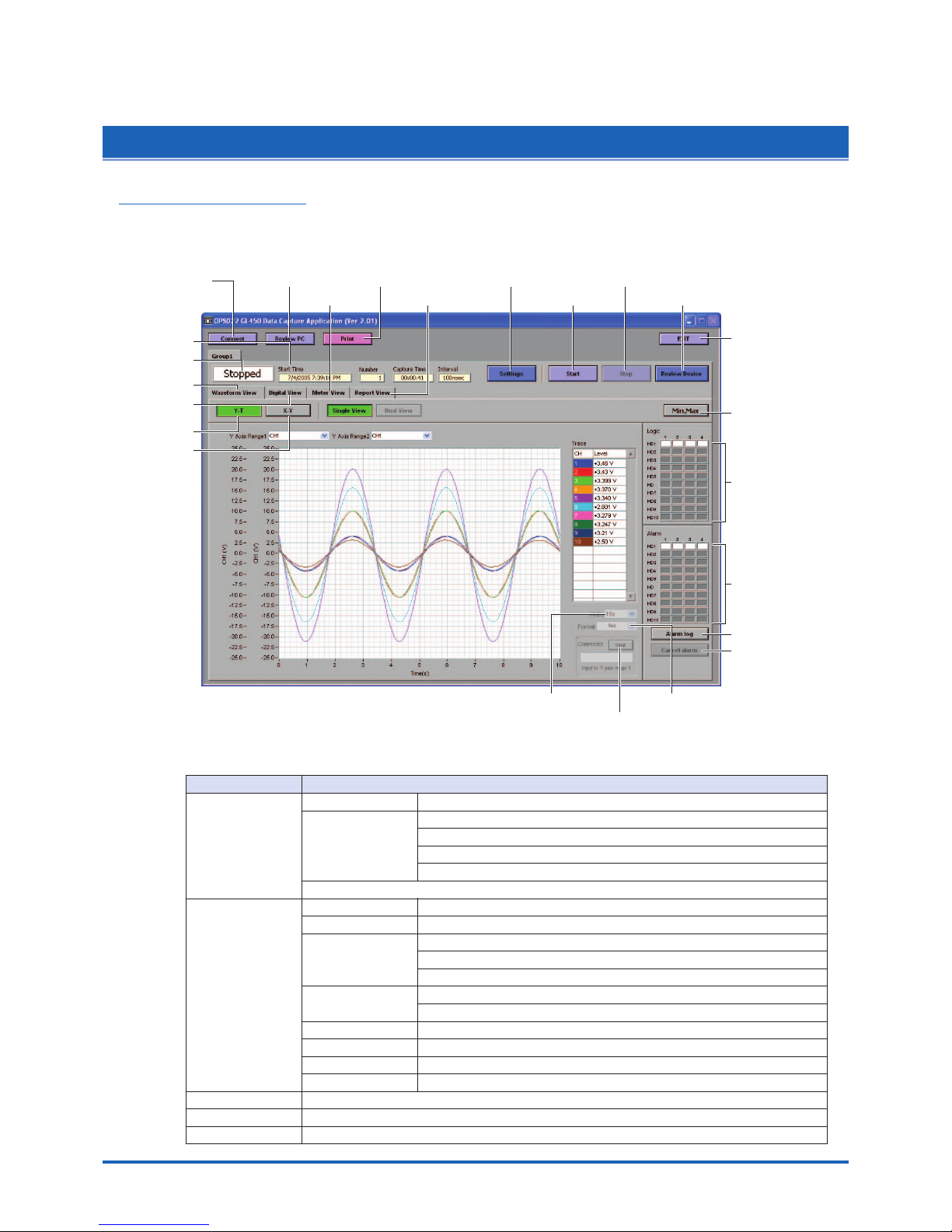
Software
4-11
4.6 Menu Configuration and System Settings
Starting the Software
Click "Start" "Programs" "OPS022" to launch OPS022. Once started, the following window is
displayed.
(1) Connect (2) Review PC
(8) Meter View (9) Report View
(12) Settings
(13) Start (15) Review Device
(14) Stop
(22) X-axis Display Width (23) Format
(10) Y-T
(5) Status View
(16) EXIT
(17) Maximum/Minimum
(20) Alarm History
(21) Alarm Cancel
(18) Logic
(4) Info Message
(6) Waveform View
(7) Digital View
(11) X-Y
(19) Alarm
(3) Print
(24) Comment
Menu Configuration
Menu Name Selections
(1) Connect Connection method USB, TCP-IP
Edit No., Name IP Address, Port, USB ID
Group: Setting groups 1 to 10
Host: Master, Slave
Status: OK/NG
Delete, Connect, Disconnect, Load Conditions, Save Conditions
(2) Review Open File
Superimpose/Link Select files to superimpose/link: Add, Delete
Convert then Save File Path: Format, Path
Data: All Cursor
Spot Samples: Off, Select from 2 to 1000 points
Open in EXCEL Data: All Cursor
Spot Samples: Off, Select from 2 to 1000 points
Print
XY Between Cursors
Calculation
Comment Input, Delete
(3) Print
(4) Info Message Start Time, Capture Number, Capture Time, Capture Interval
(5) Status View Stopped, Armed, Recording, Finished
Page 77

4-12
Software
Menu Name Selections
(6) Waveform View Single View, Dual View (during data capture only)
(7) Digital View 1-20 to 81-100, 1-50, 51-100
(8) Meter View 1-20 to 81-100
(9) Report View View in EXCEL
(10) Y -T
Single View Display, Dual View Display, Y Axis Range 1, Y Axis Range 2, X-axis Display Width
(11) X-Y
(12) Settings AMP Select CH: From 1-10 to 91-100
Analog AMP Settings: Line Color, Annotation, Input, Range, Filter, Unit
All CH: Input, Range, Filter
Logic/Pulse Settings, Device Number 1 to 10
Logic: On, Off
• Line Color: 1 to 4
Pulse: Line Color, Input, Range, Slope
X-Y XY Graph Settings: Disp., Line Color, X Axis, Y Axis
Span Select CH: From 1-10 to 91-100
CH Span Settings: Upper, Lower
Scaling Select CH: From 1-10 to 91-100
• Meas. Output: Func, Upper, Lower
• Scaling Output: Upper, Lower, Unit
Pulse Settings Device Number.: 1 to 10
• Meas. Output: Func, Upper, Value
• Scaling Output: Upper, Unit
Data Device Settings: Sampling Interval, Data Capture Setting
PC Card Settings: File Name, Format, File Path
PC Settings: Capture File Setting, Auto File Name, Format, File Path
Auto Backup Settings: Create Backup File, Backup Interval
Alarm Select CH :From 1-10 to 91-100
Alarm Settings: Function, Upper, Lower, Alarm Output, Combination
Alarm: Logic, Pulse Settings, Device Number: 1-10
Logic: Function, Alarm Output
Pulse: Function, Upper, Lower, Alarm Output
Alarm Hold: Maintains the alarm status
Trigger Trigger Settings
• Start: Function, Alarm Output, Date
• Stop: Function, Alarm Output, Date, Time
• Repeat Trigger
Level Trigger Settings
• Start: CH, Function, Upper, Lower
• Stop: CH, Function, Upper, Lower
File PC Card Operation
Data Transfer, Copy File, Delete File, Delete Folder
Device Number: 1 to 10
Card Initialize, Path, File
Report Daily Capture: Capture Interval, Destination Folder
Monthly Capture: Capture Interval, Destination Folder
Output Format: Save as CSV file, Export to Direct Excel File
CSV File Settings
• Daily Capture: Save Folder
• Monthly Capture: Save Folder
Export to Direct Excel File Settings
• Template File: Template file
• Daily Capture: Save Folder Export Sheet
• Start Cell: Horizontal, Vertical
• Monthly Capture: Save Folder Export Sheet
• Start Cell: Horizontal, Vertical
Page 78

Software
4-13
Menu Name Selections
(12) Settings Other Device Number: 1-10
• Room Temp. Compensation
• Burn out
• Output alarm when burn out (Alarm Number 4)
• Temp Unit
• AC Line Cycle
• Power On Star
• Store the setting conditions into GL450
• Synchronize PC and device clocks
• Factory Default Setting
Send E-Mail
Send E-mail when alarm is generated, Mail Address, Comments,
SMTP Server, Sender Mail Address
Information OPS022 Version, Device Information
(13) Start
(14) Stop
(15) Review Device Open File Device, Path, Create Folder, Delete, Open Memory Data File, Filter
Superimpose/Link Select files to superimpose/link: Add, Delete
Convert then Save File Path: Format, Path
Data: All, Cursor
Spot Samples: Off, Select from 2 to 1000 points
Open in EXCEL Data: All, Cursor
Spot Samples: Off, Select from 2 to 1000 points
Print
XY Between Cursors
Calculation
Comment Input, Delete
(16) EXIT
(17)
Maximum/Minimum
(18) Logic
(19) Alarm
(20) Alarm History
(21) Alarm Cancel
(22)
X-axis Display Width
(23) Format Second, Relative Time, Absolute Time
(
24
) Comment Input
Page 79

4-14
Software
4.7 PC Connection Settings
The GL450 can be connected to a computer via USB or TCP-IP (LAN).
(1) Click the "Connect" button on the main menu to display the Connect window.
Select USB or TCP-IP.
(2) Edit
Several settings need to be made to enable connection to your PC.
No.: Select a number from 1 to 10. When a number is selected, a submenu (settings list)
appears.
Name: Be sure to enter a name (any name) for device control.
Note: Input of a name is essential
CHECKPOINT
The number specified here becomes the device number, and is displayed as such in the application.
IP Address: Set the IP address for the GL450 connected (when using the TCP-IP interface).
Port: Set the port number for the GL450 connected (when using the TCP-IP interface)
USB ID: Set the ID number for the GL450 connected (when using the USB interface)
Group: When two or more GL450 devices are being used for simultaneous measurement,
register them in the same group. This setting must be made for simultaneous
measurement.
When all the settings have been made, click the "OK" button to complete the setting operation.
(3) Connect, Disconnect/Load Conditions, Save Conditions
Connect: When the "Connect" button is clicked to connect the GL450 to the computer after the
settings have been made, "OK" is displayed to indicate that the connection can be
made. Clicking the "Close" button connects the GL450 to the computer.
CHECKPOINT
"NG" is displayed if the connection conditions are incorrect. Check the condition settings once again.
Page 80

Software
4-15
Disconnect: Click this button to cancel the connected status. If the GL450 is not
connected and this button is clicked, the status display goes blank.
Load Conditions:Click this button to load previously-saved settings.
Save Conditions:Click this button to save the settings. Please specify the file name and save
destination. The file name will have a .cfg extension.
Page 81

4-16
Software
4.8 Measurement Parameters Settings
Click the "Settings" button on the main menu to enable device and measurement parameters for the GL450
to be made.
CHECKPOINT
The GL450 settings are changed whenever the "OK" or "Apply" button is clicked in each setting menu.
AMP Settings
(1) Select CH
Specify a group or groups of channels in the range [1 to 10] through [91 to 100].
Analog AMP Settings:
• Line Color: Specifies the color for each channel.
• Annotation:Up to 11 characters can be input for each channel.
CAUTION
Certain characters used here may not be displayable on the GL450 monitor.
• Input: OFF, DC, Temp, RH
Sets the input type for each channel.
CHECKPOINT
For RH, the following settings are automatically made:
DC: 1V; Scaling: 0V → 0%, 1V → 100%
• Range
DC: 20, 50, 100, 200, 500 mV, 1, 2, 5, 10, 20, 50 V
CHECKPOINT
For the 1-5V range, select 5V, and then specify 5V for the upper span limit and 1V for the
lower span limit.
Temp: Specify one of the following:
TC-K, TC-J, TC-T, TC-E, TC-B, TC-R, TC-S, TC-N, TC-W, Pt100, JPt100.
• Filter: Off, On
Select On if you need to cut noise.
Page 82

Software
4-17
• Unit: The measurement unit is displayed during measurement.
• All CH:
Sets the Input, Range, and Filter values to the same values for all the channels in the
displayed group. Click the "Set" button next to "All CH" to make the settings.
(2) Logic/Pulse Settings
Device Number: Specify which of the connected devices to use for logic input.
Logic: Off, On
Select On if a Device Number was specified.
• Line Color: Specifies the colors for channels 1 to 4.
Pulse
• Line Color: Specifies the color.
• Input: OFF, Counts, Revolutions, Inst.
OFF: Pulses are not measured.
• Revolutions: Counts the number of pulses at 1-second intervals and then multiplies them by
a factor of 60 to display them as revolutions.
• Counts: Displays the cumulative number of pulses for each sampling interval from the
start of measurement.
• Inst.: Counts the number of pulses for each sampling interval.
Range: Can be set for each of the modes.
Slope: Sets the condition for the input signal operation.
• H: Operates when the signal is a rising signal
• L: Operates when the signal is a falling signal.
Mode Range
Maximum number of pulse inputs
Revolutions 50k, 500k, 5M, 50M, 500M C/F.S. 50 k/sampling interval
Counts 500, 5k, 50k, 500k RPM/F.S. 50k/s
Inst. 50k, 500k, 5M, 50M C/F.S. 50 k/sampling interval
Page 83

4-18
Software
X-Y Settings
Specify a combination of the X channel with one of the Y channels to display measurement data in
XY format. 10 combinations are provided.
Disp.: On (Enabled), Off (Disabled)
Select On for X-Y display of the selected combination.
Line Color: Specify the colors
X Axis: Specify the channel for displaying X-axis measurement data.
Y Axis: Specify the channel for displaying Y-axis measurement data.
Page 84

Software
4-19
Span
Click the "Span" button on the main menu to enable Span settings to be made.
(1) Select CH
Specify a group or groups of channels in the range [1 to 10] through [91 to 100].
(2) Analog Span Settings
Upper: Specify the upper limit value of the set range.
Lower: Specify the lower limit value of the set range.
CHECKPOINT
For the 1-5V range, select 5V for the Amp Settings range, and then specify 5V for the upper span
limit and 1V for the lower span limit.
Page 85

4-20
Software
Scaling
Use the Scaling function to perform calculation functions on the measured values and the scaling
values.
(1) Select CH
Specify a group or groups of channels in the range [1 to 10] through [91 to 100].
Meas. Output
• Function: Off, On
• Upper: Displays the Upper Limit Value of the set span.
• Lower: Displays the Lower Limit Value of the set span.
• Unit: Displays the unit for the set range. (Display only)
Scaling Output
• Sets the converted numerals and unit when the measured values are scaled.
• Upper: Sets the Upper Limit Value to be converted.
• Lower: Sets the Lower Limit Value to be converted.
• Unit: Input the unit for conversion.
(2) Pulse settings
Device number: Specify a Device Number from 1 to 10.
Function: Off, On
• Select On to enable scaling.
• Upper: Sets the Upper Limit Value.
• Unit: Sets the unit.
Scaling Output
• Upper: Sets the Upper Limit Value to be converted.
• Unit: Input the unit for conversion.
Page 86

Software
4-21
Data
Click the "Data" button to set measurement parameters, the data capture destination, etc.
(1) Device Settings
Sampling Interval: 100, 200, 500 ms, 1, 2, 5, 10, 20, 30 s, 1, 2, 5, 10, 20, 30 min, 1 h
Specifies the sampling speed for the GL450.
CHECKPOINT
The maximum sampling interval that can be set is limited by the number of channels installed.
Data Capture Setting: Internal memory, PC card
(2) PC Card Settings
File Name: Specifies the file name for data capture.
Format: GBD, CSV
Specifies the data format for saving measurement data
File Path: Specifies the file path when saving data to a PC card.
(3) PC Settings
Capture File Name: Specifies the file name when data is captured to the computer.
Format: GBD, CSV
Specifies tmhe data format for saving measurement data.
Auto File Name: Specifies a file name automatically. The date and time are appended to
the file name.
CHECKPOINT
When the setting is Auto File Name, a folder labeled with the date on which data capture started
is created, and the data is stored to that folder.
Example: If the date is June 1, 2005, the data is stored to
Specified folder \2005-06-01\
File Path: Specifies the file path when saving data to a computer.
(4) Auto Backup Settings
Create Backup File: Check this box for auto data backup.
Backup Interval: 1, 2, 6, 12, 24 hours
Specifies the backup interval.
CHECKPOINT
• The data backup location uses the same file path set in PC Settings. The file name is automatically
assigned.
• PC Settings Capture File Name _xx_bk.GBD (xx: consecutive numbers).
Page 87

4-22
Software
Alarm
(1) Select CH
Specify a group or groups of channels in the range [1 to 10] through [91 to 100].
(2) Alarm Settings
Function: Off, Hi, Lo, Win In, Win Out
Specifies the condition for alarm generation.
Upper: Specifies the Upper Limit Value for the condition specified in Function.
Lower: Specifies the Lower Limit Value for the condition specified in Function.
Alarm Output: 1-4
Specifies the number for alarm output to an external device.
Combination: AND, OR
Specifies the condition for alarm output.
(3) Logic, Pulse Settings
Device Number: Specifies which of the connected devices to use for logic input.
Logic
• Func.: X (not used)
L (enabled when the signal goes low)
H (enabled when the signal goes high)
• Alarm Output: 1-4
Specifies the number for alarm output to an external device.
Pulse
• Function: Off, Hi, Lo
Specifies the condition for alarm generation.
• Upper: Specifies the Upper Limit Value for the condition specified in Function.
• Lower: Specifies the Lower Limit Value for the condition specified in Function.
• Alarm Output: 1-4
Specifies the number for alarm output to an external device.
CHECKPOINT
Please refer to "r ALM Settings Window" on page 3-17 for further details.
(4) Alarm hold
Hold generated alarm:
When an alarm is generated, the alarm status is maintained unless the Alarm Cancel function
is used.
Page 88

Software
4-23
Trigger
The trigger Start/Stop settings are made here.
Trigger Settings/Level Trigger Settings
Start
• Function: Sets the Data Capture Start condition.
Off: No trigger is used. Instead, measurement is initiated by pressing the
START/STOP key.
Level: The start of measurement is triggered when the trigger condition is satisfied.
Alarm: The start of measurement is triggered with the alarm condition is satisfied.
Specified Time:
(When Repeat Trigger is Off) Measurement starts (data capture starts) at
the specified date and time. (When Repeat Trigger is On) Measurement
starts (data capture starts) at the specified time.
External: The start of measurement is triggered when a signal is input from an
external trigger terminal.
• Alarm Output: Selects the alarm output when the Function is Alarm.
Stop
• Function: Sets the Data Capture Stop condition.
Off: No trigger is used. Instead, measurement is stopped by pressing the
START/STOP key.
Level: Measurement is stopped when the trigger condition is satisfied.
Alarm: Measurement is stopped when the alarm condition is satisfied.
Specified Time:
(When Repeat Trigger is Off) Measurement stops (data capture stops) at
the specified date and time. (When Repeat Trigger is On) Measurement
stops (data capture stops) at the specified time.
External: Measurement is stopped when a signal is input from an external trigger
terminal.
Time: Sets the amount of time from the start until the end of measurement. (The
time can be specified in 1- second increments).
• Alarm Output: Selects the alarm output when the Function is Alarm.
• Date, Time: Make these settings if "Specified Time" was selected for Function.
If Off was specified for Repeat Trigger, both Date and Time can be specified,
but if On was specified for Repeat Trigger, only Time can be selected.
• Time: Sets the end time when "Function" and "Time" have been set.
• Trigger Repeat: Measurement is restarted after the stop trigger is generated.
Page 89

4-24
Software
File
The settings related to files are made here.
(1) Data Transfer
Data captured at the GL450 can be transferred to a computer. Select the required file from the
File List, and click the "Data Transfer" button to transfer the data to the specified location.
(2) Copy File
Data captured at the GL450 can be copied to another destination. Click the "Copy File" button
to display the menu for selecting the file to be copied and the copy destination.
(3) Delete File
Data captured at the GL450 can be deleted. Select the file you want to delete and then click
the "Delete File" button to delete it.
(4) Delete Folder
Folders created at the GL450 can be deleted. Select the folder you want to delete and then
click the "Delete Folder" button to delete it.
(5) Format
When you click the "Initialize Card" button, a confirmation dialog box will be displayed. Click
the OK button to start the initialization process.
The PCMCIA card will be initialized. All the data captured to the card will be erased. Be sure to
make a data backup before initializing the card.
Page 90

Software
4-25
(6) Device Number
Select the devices for Synchronized measurement.
(7) Path
Select a data capture folder saved to the PCMCIA card in the GL450 card slot.
(8) File
Select a data capture file saved to the PCMCIA card in the GL450 card slot.
Page 91

4-26
Software
Report
Daily or monthly reports can be generated during data measurement.
(1) Report
Daily Capture: Check this box to enable report data to be generated daily.
Capture Interval: 1, 5, 10, 30 seconds, 1, 5, 10, 30 minutes
A daily capture file is automatically created for the measured data according
to the capture interval specified.
Monthly Capture: Check this box to enable report data to be generated monthly.
Capture Interval: 1, 5, 10, 30 minutes, 1, 2, 6, 12, 24 hours
A monthly capture file is automatically created for the measured data
according to the capture interval specified.
Output method: Select the output format. Save the data as a CSV file, or export it to a direct
Excel file.
(2) Configure CSV file
Daily Capture (Save Destination Folder):
Specifies the folder for saving daily capture data. The file name becomes "Daily Date
Time.csv".
Monthly Capture (Save Destination Folder):
Specifies the folder for saving monthly capture data. The file name becomes "Monthly
Date Time.csv".
(3) Configure to transfer to Excel
Template file: Specifies the Excel file for export.
CHECKPOINT
• There are several templates stored in the Temp folder contained in the installed OPS022 folder.
Use one of these templates or create your own template if desired.
• Daily capture and monthly capture data can be exported to separate sheets in the same Excel file.
Daily Capture:
• Export Destination Sheet:
Specifies the export sheet name for the Excel file specified by the template file.
• Start Cell: Specifies the start cell position on the export sheet.
Monthly Capture:
• Export Destination Sheet:
Specifies the export sheet name for the Excel file specified by the template file.
Page 92

Software
4-27
• Start Cell: Specifies the start cell position on the export sheet.
CHECKPOINT
•Take care with the data sequence (No., Date, Ch1, Ch2, ..., CHN, Pulse, Logic, Alarm: CHN is
determined by the number of data capture channels).
• This function can only be used if the Microsoft Excel software program is installed in your
computer.
• There is a limit to the amount of data that can be exported. The maximum number of data points
is 64000.
Page 93

4-28
Software
Other
The GL450 device settings and email settings when an alarm has been generated are made here.
(1) Device Number
Specifies the Device Control Number for settings.
(2) Room Temp Compensation: Off, On
This function is only used when a temperature range has been specified. "On" is normally
selected. When making this setting, there is a choice between Internal (the GL450's room
temperature compensation settings are used) or External. Select External when you have the
necessary equipment and know-how.
(3) Burn Out: Off, On
This function is only used when a temperature range has been specified. It is normally set to
"On". When a thermocouple sensor has burnt out, that status is displayed on the screen.
(4) Output alarm when burn out (Alarm Number 4)
Alarm number 4 is output if a burnout occurred during temperature measurement.
(5) Temp Unit: Celsius (°C), Fahrenheit (°F)
Select the setting that you want to be displayed during temperature measurement.
(6) AC Line Cycley
Select the AC line frequency that matches the one normally used.
(7) Power On Start: Off, On
This function enables the settings that were in effect when measurement last ended to be used
to start measurement as soon as the power is switched on. (Data being measured using the
OPS022 software cannot be captured when the Power On Start function is used).
CHECKPOINT
•
If Power On Start is used to activate the GL450 and then the device is connected using the OPS022
application, the OPS022 status is displayed during data capture (waveforms are not displayed).
• If Power On Start is enabled while the device is being connected using the OPS022 application,
restart the OPS022 connection procedure (disconnect and then reconnect).
(8) Store the setting conditions into GL450: On (save settings), Off (do not save settings)
This parameter selects whether or not to save the software settings to the GL450.
(9) Synchronize PC and device clocks
Click this button to change the GL450's clock setting to match that of the computer.
(10)Factory Default Setting
This parameter returns all the settings to the factory defaults. Use this function when you want
to start from scratch.
Page 94

Software
4-29
(11) Send E-mail
Send E-mail when an alarm is generated: Check this box to enable this function.
Mail Address:Email can be sent to five locations.
Please set the addresses in accordance with your computer system.
Comments: Comments can be recorded for each email setting to explain the contents.
(Email is actually sent when an alarm is generated.)
Page 95

4-30
Software
Information
The device status control information is displayed. This information can be used for maintenance
purposes, but it cannot be input directly.
Page 96

Software
4-31
4.9 View Functions
The display can be changed to suit the type of measurement being performed. It is also used to perform
measurements and make settings.
Capture Start/Stop
When the measurement conditions have been set, waveforms are displayed even though
"Finished" is displayed. However, when the GL450 is connected to a computer, the waveforms are
monitored. If "Start" is selected in this status, the display changes to "Recording", and
measurement starts according to the settings made in the setting menus.
Page 97

4-32
Software
Waveform View
The waveform view "Y-T" display can be selected as "Single View" or "Dual View". When the GL450 is
in on-line status, the measured waveforms are always displayed. Moreover, when data capture has
been started, the data is captured according to the settings made in the setting menus.
Y-T
Measurements can be displayed with respect to the time axis.
(1) Single View Display
The X axis is the time axis, and the Y axis displays the measurement range specified for each
channel.
Y Axis Range 1, 2: The Y axis scale can be displayed as the scale for two channels.
Channel If a channel's color display is clicked to turn it off, the waveform for that
channel will not be displayed.
X-axis Display Width: The time axis width can be changed if the numeric value is changed.
Note: Measurement data is captured.
Format: Second, Relative Time, or Absolute Time can be selected for the X-axis
display.
Comment Function: During data capture, a comment can be input above the Y axis range 1
waveform. Comments that were input can be checked during a Review
PC operation, and can also be changed or added to if required.
Note: This function is only enabled during data capture.
Page 98

Software
4-33
(2) Dual View Display
Data captured in the past can be displayed alongside the data that is currently being captured.
Note: This function can only be used while data is being captured.
Past data can be enlarged and checked using the on-screen cursors.
When the display is Dual View, the cursor
display can be used to search data.
Cursor, Enlarge/Compress,
Move Display, Auto Scale
Click on the "Cursor", "Enlarge/Compress", "Move Display" and "Auto Scale" icons to select them.
"Enlarge/Compress" selection screen.
X-Y
The X axis can be combined with a Y axis for an X-Y display. Specify the X and Y channels in "XY"
under "Settings".
Page 99

4-34
Software
Digital View
Digital data can be displayed separately for each group. If the group is a 20-channel group, pulse
measurements can also be displayed. For a 50-channel group, however, only digital is displayed.
(1) 20-channel group displays: 1 to 20, 21 to 40, 41 to 60, 61 to 80, 81 to 100.
(2) 50-channel group displays: 1 to 50, 51 to 100.
CHECKPOINT
Only the channels in the input terminal units that are installed in the GL450 are displayed. "*****" is
displayed for channels that are not installed.
Page 100

Software
4-35
Meter View
The measured data is displayed in a meter format. Use this view when you want to monitor the
status with the feeling of using an analog meter. Moreover, this display can be changed in group
lots.
CHECKPOINT
The alarm setting ranges are displayed in red in the Meter View screen.
 Loading...