

Page 1
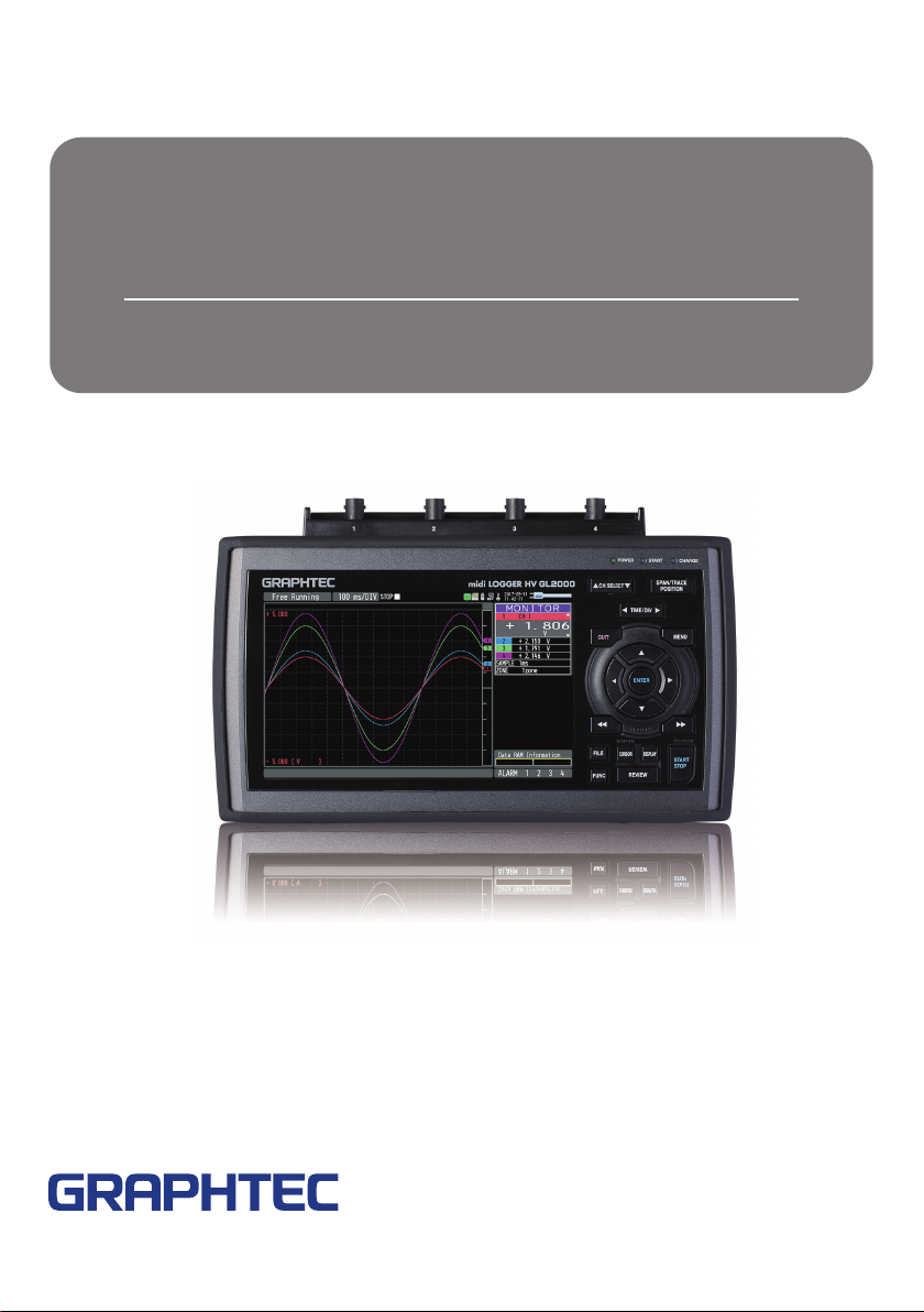
midi LOGGER HV
GL2000
Quick Start Guide
604929220 GL2000-UM-851
Page 2

Thank you for choose the midi LOGGER HV GL2000.
This Quick Start Guide describes the basic operations.
Please refer to the manual (PDF) in the CD-ROM for more information.
The explanation on how to use the ferrite core, tilt stand, and M3.5 screw
can be found in the manual above. Please refer to them.
Checking the Outer Casing
After unpacking, check the GL2000's Exterior to make sure that
there are crack or other damage before use.
Checking the Accessories
• Quick Start Guide : 1 • Ferrite core: 3 • CD-ROM : 1
• AC cable/AC adapter : 1 •
•
M3.5 screws: 1 set
•
Tilt stand: 1 set
Notes for Safe Operation: 1
Contents
Nomenclature ……………………………………………………… 2
Connection Procedures ……………………………………………3
Precautions to Observe When Taking Measurementt
Descriptions of the Control Panel Keys ………………………… 6
Descriptions of the Menu Screens …………………………… 10
Measurement Procedure………………………………………… 14
1. Preparation for measurement
2. AMP setting …………………………………………………………………… 15
DATA setting
3.
Recording and stopping
4.
Playback method
5.
Specifications
Standard Specifications
Specification of input section …………………………………………………… 21
Specification of
……………………………………………………………………17
………………………………………………………………19
………………………………………………………20
…………………………………………………………20
Input/Output
…………………………………………………
……………………………………………………… 18
section …………………………………………… 22
Installation Guide …………………………………………………22
………… 5
14
1
Page 3
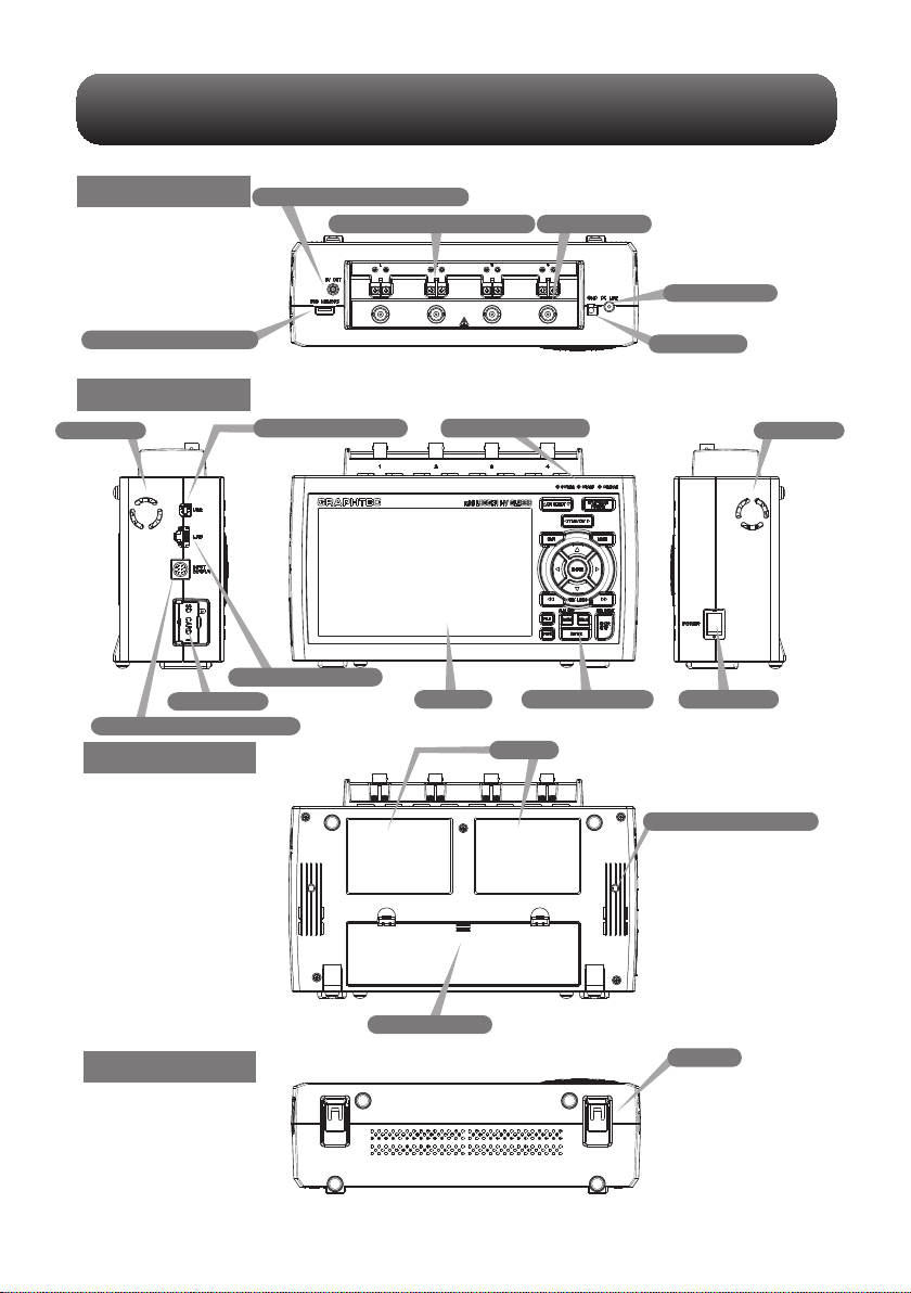
Top Panel
Top Panel
Top Panel
Nomenclature
Power jack for humidity sensor
Analog signal input terminals
Input terminals
AC adapter jack
USB memory terminal
Front Panel
Front Panel
Front Panel
FAN air exit FAN air exit
SD card slot
External input/output terminals
Bottom Panel
Rear Panel
USB interface terminal
LAN interface terminal
Operation status LED
Monitor
Label
Control panel keys
GND terminal
Power switch
Tilt stand fixing screw
Battery cover
Bottom PanelBottom Panel
The illustration without cover is used for explanation purpose.
Tilt foot
2
Page 4

Connection Procedures
Connecting the AC Adapter
Connect the DC output of the AC adapter to the
connector indicated as "DC LINE" on the GL2000.
Connecting the Grounding Cable
Use a flathead screwdriver to push the button above
the GND terminal while connecting the grounding
cable to the GL2000. Connect the other end of the
cable to ground.
Making Connections to the Analog Input Terminals
CH4 CH1
CAUTION: Connect wires to the specified channel, the channel number is shown on current of the terminal
block
DC voltage input
+ −
DC voltage
Current input
+ −
DC curren
Thermocouple input
+ −
Compensationcopper wire
Ex: The current is converted to the
voltage in the shunt register.
For 4 to 20mA current input, installing
250 ohms
(0.1%) resister for converting 1 to 5V.
Making Connections to the External Input/Output Terminals
< Signal assignment >
* The B-513 input/output cable for GL2000 (sold separately) is required for connecting input/output signals.
(For logic/pulse input, alarm output, trigger input, external sampling pulse input)
Orange with red dotted line : 1
Orange with black dotted line : 2
Grey with red dotted line : 3
Grey with black dotted line : 4
White with red dotted line : 1
White with black dotted line : 2
Yellow with red dotted line : 3
Yellow with black dotted line : 4
Pink with red dotted line : Trigger input/External
Pink with black dotted line
Shielded
Logic/Pulse
input
Alarm output1 /
Trigger output
Alarm output
sampling input
GND
3
Page 5

Internal / External memory
This device is equipped with internal RAM and internal memory. The internal memory
is not removable.
An SD card and USB memory are available.
* Make sure that the SD card
is not locked.
Lock
DRAC DS
x GB
SD card
USB memory
4
Page 6

Precautions to Observe When Taking Measurement
To avoid break-downs or short-circuiting accidents, please make sure to follow warnings written
below.
• Use only the AC adapter provided as a standard accessory. The rated power supply range for the adapter is 100 to
240 VAC, and the rated frequency is 50/60 Hz. Do not use any other voltages.
• Do not input the voltage that exceeds the specification of this device.
∙ If a voltage exceeding the specified value is input, the semiconductor relay in the input section will be damaged.
Never input a voltage exceeding the specified value even for a moment. It will cause fire.
∙ Have enough margin from the specification of withstanding voltage when using this device, it has to consider a
noise and change of the measurement voltage.
∙ Confirm this device is not broken before the input cable is connected to the input terminal.
∙ Please take care of the static electricity when connecting the input cables or the thermocouples.
∙ Do not touch the tip of thermocouples with bare hand after the thermocouples are connected to the terminal of this
device when the tip is not insulated.
The static electricity from a human body will cause damage to the device.
∙ Do not put the tip of thermocouples to an object which contains static electricity when the tip is not insulated.
The static electricity from object will cause damage to the device.
∙ Do not put the tip of thermocouples to the object which contains leaked high voltage from chassis or metal etc.
when the tip is not insulated.
The leaked high voltage from object will cause damage to this device.
∙ We recommend that an insulation tape is placed on the tip of thermocouples before connecting it to the input
terminals.
This will protect the device from the static electricity and the leaked high voltage.
• To prevent electric shock and short circuit accident, do not connect to BNC terminal and screw terminal at the same
time.
When using
Please be sure to read the following carefully in order to prevent electric shocks or short circuit.
Maximum input voltage
•
If a voltage exceeding the specified value is input, the parts in the input area will be damaged.
Never input a voltage exceeding the specified value even for a moment.
< Between +/– terminals A >
• Maximum input voltage: Range of 20mV to 2V : AC/DC 30V
<Between input terminal and input terminal B >
Maximum input voltage: AC/DC 600V( CATⅢ)/AC/DC 300V( CAT Ⅳ)
Withstand voltage: AC/DC5400V at 1 minute
<Between input terminal and GND C >
Maximum input voltage : AC/DC 600V( CATⅢ)/AC/DC 300V( CAT Ⅳ)
Expected transient overvoltage : AC/DC5400V at 1 minute
Range of 5V to 1000V : AC/DC 600V
[ Temperatur e measuring ][ Voltage meas uring ]
+
A
-
B
B
+
C
-
+
-
C
GND
+
-
+
-
+
-
GND
B
C
5
Page 7

Descriptions of the Control Panel Keys
This section describes key operation.
(1) CH SELECT
(5) QUIT
(13) FILE
(14) FUNC
(12) CURSOR (ALARM CLEAR)
(10) REVIEW
1. CH SELECT
Moves CH and item in monitor display.
Use keys of CH SELECT to move up and down.
(2) SPAN/TRACE/POSITION
(3) TIME/DIV
(4) MENU
(6) DIRECTION KEYS
(7) ENTER
(8) FAST FORWARD
(9) START/STOP
(11) DISPLAY
(KEY LOCK)
(USB DRIVE MODE)
2. SPAN/TRACE/POSITION
Switches the information in the monitor display.
This is used to change the settings related to waveform.
3. TIME/DIV
Press this key to change the time axis display width.
4. MENU
Press this key to open the setting window. Each time you press the key, the setting window
changes as follows.
AMP→DATA→DISP→TRIG→I/F→OTHER
6
Page 8

5. QUIT
This key is primarily used for the following operations.
To cancel a setting when setting MENU.
To return to the MONITOR screen while the SPAN/TRACE/POSITION key is operated.
To cancel the interface restriction (When the keys are disabled).
To exit the replay display.
6. Direction Keys
These keys are primarily used for selecting the item while setting menu and span setting
during digital display.
7. ENTER
To fix setting items during menu configuration or finalize.
8. FAST FORWARD key (KEY LOCK)
This key is primarily used for the following operations.
To move the cursor at high speed during replay.
To change the display order of the files in the file selection tool.
To set key lock (Hold down the left/right FAST FORWARD key for at least two seconds.
Press again to unlock.)
To set a password for cancelling the key lock.
(For the instructions on how to cancel the key lock, refer to the article related to the Key
lock in the User's Manual.)
9. START/STOP(USB Drive Mode)
In the "USB Drive Mode", check the internal memory and SD card as external storage devices
on the PC.
To enter the USB Drive Mode, press down this key from when the power is turned on until the
display below appears.
When the display below is displayed, the device is recognized as removable disk and files can
be transferred and deleted from the PC.
7
Page 9

10. REVIEW
This key is used to replay captured data.
During Free Running, captured data is replayed.
During capturing, captured data is replayed.
(Data replay Source is displayed on the status display. Press again to return to the
capturing data screen.)
To exit the replay display, press the [Quit] key.
11. DISPLAY
This key is used to switch the screen mode. Press this key to show the following screen.
When running Free Running
Displays the Y-T waveform + Digital display> All waveform screen> Logging display+Real
time statistical calculation screen > XY screen
12. CURSOR(ALARM CLEAR)
Press this key during replay to switch between cursors A and B.
When the alarm setting is set to "Hold generated Alarm", the alarm is cleared.
13. FILE
This key is used to perform the file-related operations.
14. FUNC
Take a shortcut with the key by selecting the frequently used function in advance.
For details of function operation, refer to "3.5 Setting Menus" - "(6) OTHER settings" - "FUNC
key settings".
8
Page 10

15. Key lock release with password
A password can be set to device to cancel the key lock.
(No password is set at factory default.)
<Operation Flow>
1. Set the password.
Press the , , and ENTER keys at the same time to display the password setting screen
shown below. Specify a four-digit password.
Use the , ,
password.
In case you forgot your password, please contact us to acquire the master password.
2. Set the key lock operation.
Hold down the and keys together for at least two seconds.
3. Cancel the key lock.
Hold down the and keys together for at least two seconds.
The password setting screen shown below will be displayed. Set a password.
Entering an incorrect password will not unlock the key lock.
Key lock status will be retained when power is turned off.
keys to select numbers and press the [ENTER] key to fix the
,
9
Page 11

Descriptions of the Menu Screens
2. Time/DIV display area
1. Status message display area
19. Data capture bar
17. Scale upper limit
18. Waveform display area
17. Scale lower limit
1.
Status message display area
2.
Time/DIV display area
3.
Status mark
: Appears when neither capture nor replay is in progress.
: Displayed when the captured data is being recorded.
: Appears when waiting for a trigger during capturing and for the stop key after capturing.
: Displayed when replaying the captured data.
: Displayed when replaying during capturing the data (Refer to in “3.2 Key Operation” - “(10) REVIEW”.).
16. File name display area
: Displays the operating status.
: Displays the current time scale.
: Displays the status mark.
5. Device access display
(SD card)
4. Device access display
(Internal memory)
3. Status mark
:
15. Level bar
6. Device access display
(USB memory)
7. Remote lamp
8. Key lock display
9. Clock display
10. AC/Battery status indicator
11. Digital display area
12. Quick settings
13. Internal RAM
information
14. Alarm display area
Please do not turn Off the power and do not remove the SD card or USB memory when the status mark indicates
other than “STOP”. The data is damaged, and it will not be accessable.
Please start the operation after making sure that the status mark is switched to "STOP".
4.
Device access display (Internal memory)
: Internal memory is recognized but is not being accessed.
: Internal memory is being accessed. While the internal memory is being accessed, the POWER LED also flashes.
10
Page 12

Device access display (SD card)
5.
: SD card is not attached.
: SD card is attached but not being accessed.
: SD card is accessed. Do not remove SD card. The POWER LED light also flashes while the SD card is
being accessed.
Please do not remove the SD card and do not turn Off this device’s power when accessing the SD card.
The data is damaged, and it will not be accessable.
Device access display (USB memory)
6.
: USB memory is not attached.
: USB memory is attached but not being accessed.
: USB memory is accessed. Do not remove USB memory. The POWER LED light also flashes while the
USB memory is being accessed.
Please do not remove the USB memory and do not turn Off the power when accessing the USB memory.
The data is damaged, and it will not be accessable.
Remote lamp
7.
: Indicates local mode. Operations can be conducted on this device.
: Indicates remote mode. With some exceptions, operations must be conducted on a PC.
When you cancel the connection on the application (GL980_2000-APS), this device automatically rerturns to local
mode. If local mode is not entered, press the [QUIT] key.
Key lock display
8.
: Not in key lock status. Normal operations are permitted
: Key lock status. All the keys are locked.
For details of the key lock, refer to "3.4 Setting Menus" - "(14)Key lock release with password".
11
Page 13

Clock display
9.
Displays the current date and time.
For details on date and time settings, refer to “3.5 Setting Menus” - “(6) OTHER settings”.
AC/Battery status indicator
10.
: Running on AC or DC power supply.
: Running on battery. The remaining battery power is 100 to 91%.
: Running on battery. The remaining battery power is 90 to 61%.
: Running on battery. The remaining battery power is 60 to 31%.
: Running on battery. The remaining battery power is 30 to 11%.
: Running on battery. The remaining battery power is 10% or below.
• Data capture automatically stops when the remaining battery power drops to 10% or below during.Auto Save will
be performed even when Auto Save is not set while data is being captured to the internal RAM.
• The power is automatically turned off when the remaining battery power is 0%.
• Use the remaining battery display only as a reference.
This indicator does not guarantee the exact operating time of a battery.
Digital display area
11.
Displays the input value of each channel and span. Use the [SPAN/TRACE/POSITION] keys to switch the display.
Use the keys to select the channel you want to activate (enlarged display).
: Displays the input value.
: The span of the active channel can be changed using the keys.
: The position of the active channel can be changed using the keys.
: The ON or OFF of the active channel display can be changed using the keys.
For details, refer to “3.2 Key Operation” - “(2) SPAN/TRACE/POSITION”.
As described below, the CH indicating the calculation mark is the channel which calculation between the CHs is
enabled (On).
Calculation mark
12.
Quick settings
The settings of the sampling interval and the division of waveform display can be changed. Use the keys to
activate the Quick setting and the left/right keys to change values.
* The "SAMPLE" item cannot be changed during data capture.
13.
Internal RAM information
Displays the status of the internal RAM. The status of the block can be judged by the color of each block.
For the number of blocks, set the division number by "memory block division".
12
Page 14

14.
Alarm display area
Displays the alarm output status.
The number with which an alarm went off is displayed in red. The channel with the alarm threshold has a red input
value in the digital display area.
15.
Level bar
Displays the each channel signal position, trigger position and alarm range.
Trigger pos ition Alarm range
Rising Falling Win In Win Out
Stop posi tion
Start p osition
16.
File name display area
(1) During data capture
A file name is displayed during the recording.
* If the ring capturing setting is ON, a file name displayed during capture ends with "_RINGx" (x represents a
number) but the actual file name does not include "_RINGx".
In the above figure, if the ring capturing is set to ON, the file name during capture will be displayed, for
example, as "<MEM>170711\PREFIX_170711-130955_RING4.GBD" but the actually created file will be
"<MEM>170711\PREFIX_170711-130955.GBD".
* For details, refer to “3.5 Setting Menus” - “(2) DATA settings”.
(2) During data replay
Information on the time axis of the cursor is displayed during Y-T replay.
Time to whi ch the cu rsor poi nts
Sele cted cu rsor
17.
Scale upper/lower limit
Displays the scale upper/lower limit of the currently active CH.
18.
Waveform display area
Displays the Y-T waveform of the input signal.
(The vertical axis is measured value and the horizontal axis is time.)
19.
Data capture bar
(1) During data capture
A capture file name is displayed during capture.
Elapse d time Remainin g time for d ata cap ture
Used ca pacit y of inte rnal me mory, SD
card an d USB mem ory
Total capa city of in ternal m emory, SD c ard and USB m emory
Remainin g capac ity of int ernal m emor y, SD
card an d USB mem ory
13
Time dif ference bet ween Cursors A and B
Page 15

For example, when you are using a 4GB SD card with 100MB already used, the total capacity of the SD card is
4GB with 100MB used space, and the available space of the SD card would be approximately 3.9GB. As the
captured time elapses, the usage of the SD card increases and the remaining capacity of the SD card
decreases.
The remaining recording time indicates the remaining capacity of the SD card.
However, when the relay capturing function is set to Off, and when the remaining capacity of the SD card
exceeds 4GB, the remaining time that can be captured to 1 file will indicate 4GB.
* Remaining time which is more than 99999 hours is displayed as "++++:++:++".
(2) During data replay
Displays the display position, cursor position, and trigger position graphically.
Cursor A p osition Cursor B p osition
Captur e data si ze
Range fo r which a wave form is currently
displaye d
Measurement Procedure
This section describes how to make capturing settings and replay captured data.
The following captured data is explained.
1CH: Sets the temperature environment using the measurement temperature and the type T
thermocouple.
2CH: Measures the voltage and fading voltage.
Sampling interval: 1 second
Data storage destination: SD card
1. Preparation for measurement
1. Connect the type T thermocouple to the screw terminal of 1CH.
2. Connect the fading voltage to the BNC terminal of 2CH.
3. Turn on the power of the main unit.
14
Page 16

2. AMP setting
1. Press the [MENU] key
The AMP setting screen will appear.
2. Press the direction keys to match the CH1 input setting.
Set to TEMP.
Press the direction keys to match the CH1 range setting.
3.
Set to TC-T.
15
4. Press the direction keys to match the CH1 filter setting.
Set to Line.
(Please set the filter when measuring the temperature.)
Page 17

5. For 2CH, set Input to DC, Range to 10V, and Filter to Off.
6. Set Input to Off for 3CH to 4CH.
7.
When the setting is complete, press the [QUIT] key to finish the AMP setting.
16
Page 18

3. DATA setting
1. Or press the [MENU] key twice.
Press the MENU key and the direction key to display the DATA setting screen.
2. Set the sampling interval to 1 s.
3.
Set the capture destination to the SD CARD, and the file name to CSV.
For the file name setting (arbitrary, serial number) refer to the operation manual of
the main unit.
If Name Type is set to Auto, the file is created with the name containing the last
two digits of the year, the month, and the day. To confirm the setting, press [OK]
17
4. When you are done, press the [QUIT] key to finish the DATA setting.
Page 19

4. Recording and stopping
1.
When the setting is completed, press the [START] key to start recording.
When "Do you want to start recording?" is displayed, recording is started by
pressing the [ENTER] key. During recording, the status at the top left of the screen
will be displayed.
2. Press the [STOP] key again to stop recording.
When "Do you want to stop recording?" is displayed, press the [ENTER] key to
stop recording.
18
Page 20

5. 再生方法
5. Playback method
1.
To check the recorded data value press the direction keys to change the CH and
the cursor. Pressing the fast forward key will move the cursor at high speed.
2. If you press the [MENU] key during playback, you can search for
3.
When recording stops, it automatically switches to recorded data playback.
playback data and calculate between cursors.
To end auto play press the [QUIT] key and follow the onscreen guidance.
19
19
4. To recall a file again, press the [REVIEW] key to select the most
recently recorded data.
Page 21

Specifications
Standard Specifications
Item
Number of analog CHs
External output terminal
PC I/F
Internal memory device
Clock accuracy
(23°C environment)
Power supply
Power consumption
• AC power consumption
(when using the AC
adapter provided as a
standard accessory)
AC100V
When the LCD is on
When the screen saver is
operating
AC240V
When the LCD is on
When the screen saver is
operating
• DC power consum
+24V
When the LCD is on
When the screen saver is
operating
+12V
When the LCD is on
When the screen saver is
operating
+8.5V
When the LCD is on
When the screen saver is
operating
External dimensions
(approximate)
Weight (approximate) *1
4CH fixed
Trigger input (1ch) or external sampling (1ch)
Logic input (4ch) or pulse input (4ch)
Alarm output (4ch) or trigger output (1ch) + alarm output (3ch)
Ethernet (10BASE-T/100BASE-TX) USB (compatible with high-speed) standard-included
Internal RAM : 4MW/CH
Internal memory : Approx. 4GB Flash
Setting conditions: EEPROM/Clock: Lithium secondary batteryData backup functions
Network time setting Off: ± 0.002% (monthly difference of approx. 50 seconds)
Network time setting On: ± 0.01% (day difference about 8.6 seconds) (Maximum
error after synchronization)
0 to 40°C, 5 to 85% RH (15 to 35°C when battery is used)Operating environment
• AC adapter : 100 to 240 VAC, 50 to 60 Hz
• DC input : 8.5 to 24 VDC
• Battery pack (option) : 7.2 VDC (2900 mAh), two packs can be mounted
Normal During recharging battery
28VA 42VA
24VA 39VA
Normal During recharging battery
39VA 59VA
34VA 55VA
ption
260(W)×161(H)×83(D) mm
1.7 kg
*1: (AC adapter and battery are not included.)
Normal During recharging battery
0.50A 0.81A
0.43A 0.76A
Normal During recharging battery
1.00A Recharging not possible
0.85A Recharging not possible
Normal During recharging battery
1.46A Recharging not possible
1.22A Recharging not possible
Description
20
Page 22

Specification of input section
DescriptionItem
Number of input channels 4CH fixed
Input terminal
type
Input method All CH insulation, unbalanced input, all CH simultaneous sampling
Fastest Sampling interval 1 μs
Measurement
ranges
Measurement accuracy
(23°C ±5°C)
When 30 minutes or more have
•
• GND connected
• Vertical placement
• Filter Line
(Voltage, Temperature)
Reference contact compensation accuracy
Temperature coefficient
Input resistance
Allowable signal source rWithin 1 kΩ
Maximum permissible input
voltage
Withstand voltage
Insulation resistance
Common mode rejection ratio
S/N (Noise) 20 mV range: -40 dB or more (at +/- short)
Frequency response DC to 200 kHz (+1/-4 dB)
Filter OFF, Line, 5 Hz, 50 Hz, 500 Hz, 5 kHz, 50 kHz
21
Voltage
Temperature
Voltage
Temperature
Humidity
Insulated BNC connector or M3.5 screw terminal unit
(However, it cannot input to the BNC connector of same CH and the screw terminal at the same time.)
M3.5 screw type terminals (Rectangular flat washer)
20・50・100・200・500mV・1・2・5・10・20・50・100V
200・500・1000V(Max .rated safety voltage:±600VDC)、1-5VF.S.
Thermocouples : K, J, E, T, R, S, B, N, W (WRe5-26)
RMS
0 to 100% (Voltage 0 to 1V scaling conversion) * B-530 (option) used
10・25・50・100・250・500mV・1・2.5・5・10・25・50VrmsF.S、
100・250・500・1000Vrms(Max .rated safety voltage:±600Vrms)F.S
* Crest Factor: in 1000Vrms range,up to 1.4 ,in other range, up to 2
* Measurable frequency: 20 to 10 kHz
* The true effective value (RMS) of AC + DC is measured
* The function to automatically obtain the effective value (RMS) and the operation
cross value from the currently measured value is provided
Voltage
•
Thermocouple
•
Thermocouple
Reference contact compensation accuracy
RMS(Average)
•
Internal/External switching
Detectable in dedicated mode (Not detectable during capturing)Burnout detection
16-bit (Effective resolution: Approx. 1/40000 of the +/- range)A/D converter
Gain : 0.01% of F.S./°C
Zero : 0.02% of F.S./°C
1MΩ ±5%
Within 1 kΩ
Between each input (+) terminal and each input (-) terminal: 20 mV to 2 V AC/DC 30V
5V to 1000V AC/DC 600V
Between each input terminal and each input terminal: AC/DC 600V( CATⅢ) / AC/DC 300V (CAT Ⅳ )
Between each input terminal and GND terminal: AC/DC 600V( CATⅢ) / AC/DC 300V (CAT Ⅳ )
*Expected transient overvoltages 6000V
Between each input terminal and each input terminal:AC/DC 5400V 1 minute
Between each input terminal and GND terminal: AC/DC 5400V 1 minute
Between Input Ch and GND terminal: 50MΩ or more (At 500 VDC)
90 dB or more (50/60 Hz; signal source 300Ω or less)
Other range: -50 dB or more (at +/- short)
Attenuation -3 dB/Cutoff frequency Slope 6 dB/oct
R/S
B
K
E
T
J
N
W
±0.25% of F.S.
* Thermocouple diameters T - K: 0.32 φ, others: 0.65 φ
Measurement Temperature Range (°C)
0 ≤ TS ≤ 100℃ ±7.0℃
100 < TS ≤ 300℃
R : 300 < TS ≤ 1600℃
S : 300 < TS ≤ 1760℃
400 ≤ TS ≤ 600℃
600 < TS ≤ 1820℃
-200 ≤ TS ≤ -100℃
-100 < TS ≤ 1370℃
-200 ≤ TS ≤ -100℃
-100 < TS ≤ 800℃
-200 ≤ TS ≤ -100℃
-100 < TS ≤ 400℃
-200 ≤ TS ≤ -100℃
-100 < TS ≤ 100℃
100 < TS ≤ 1100℃
-200 ≤ TS < 0℃
0 ≤ TS ≤ 1300℃
0 ≤ TS ≤ 2315℃
±1.5% of F.S. (Sine wave, 20 to 10 kHz)
Measurement Accuracy
±5.0℃
± (0.05% of rdg +3.0℃)
± (0.05% of rdg +3.0℃)
±5.5℃
± (0.05% of rdg +3.0℃)
± (0.05% of rdg +3.0℃)
± (0.05% of rdg +2.0℃
± (0.05% of rdg +3.0℃)
± (0.05% of rdg +2.0℃)
± (0.1% o f rdg +2.5℃)
± (0.1% o f rdg +1.5℃)
±3.7℃
±2.7℃
± (0.05% of rdg +2.0℃)
± (0.1% o f rdg +3.0℃)
± (0.1% o f rdg +2.0℃)
± (0.1% o f rdg +2.5℃)
±1.0℃
Page 23

Specification of input/Output section
Item
Input/output types
Input specifications
Alarm output
specifications
Trigger output
Pulse input Pulse sampling interval: 10 μs to 1h
External sampling input Maximum input frequency: 100 kHz
Trigger input (1 ch) or External sampling input (1 ch)
Logic input (4 ch) or Pulse input (4 ch)
Alarm output (4ch), or Trigger output (1ch) + Alarm output (3ch)
* Trigger input and external sampling input can be switched.
* Alarm output and trigger output can be switched.
Maximum input voltage : 0 to +30V (single-ended ground input)
Input threshold voltage : Approx. +2.5V (logic input, pulse input)
Approx. +1.9V (external trigger, external sampling)
Hysteresis : Approx. 0.5V (+2.5V to +3.0V) (Logic input, pulse input)
Approx. 0.2V (+1.9V to +2.1V) (external trigger, external sampling)
Output format: Open collector output (5 V, pull-up resistance 10 kΩ)
Contact capacity 5V to 24V, 100mA or less (0.2W or less)
Output conditions: Level judgment, window judgment, logic pattern
judgment, pulse judgment
When a trigger is detected after trigger output is set, a pulse of approx.
500 μs width is output from the Output 1 terminal. (Low active)
* Set it separately from sampling interval.
Setting faster than sampling interval is not possible (constant multiple)
Revolutions mode (engines, etc.)
Function: Mode to convert to the number of revolutions per minute by applying magnification
after counting the number of pulses for each pulse sampling interval.
Span: 10 to 500M
Counts mode (electric meters, etc.)
Function: Mode to accumulate the number of pulses for each pulse sampling interval from
the start of measurement
Span: Automatic (Maximum 20M)
Inst. mode
Function: Mode to display the number of pulses for each pulse sampling interval.
The accumulated value for each pulse sampling interval is reset.
Span: 10 to 20M
Maximum number of pulse inputs
Maximum input frequency : 100 kHz
Maximum number of count : 15 MC (24-bit counter)
Temporal error: 1 μs or less.
Description
Installation Guide
For the install procedure of the GL2000 application software refer to the
“Application Software Manual” included in the attached CD-ROM.
22
Page 24

Specifications are subject to change without notice.
GL2000 Quick Start Guide
(GL2000-UM-851)
Publisher GRAPHTEC CORPORATION
November 1, 2017
1st edition-01
 Loading...