

Page 1

FC
FC
7000
SERIES
user manual
MANUAL NO. FC7000-UM-151
Page 2

ii
Table of Contents
TO ENSURE SAFE AND CORRECT USE .............................................................................................vii
Conventions Used in This Manual.........................................................................................................vii
Description of Safety Symbols ..............................................................................................................vii
PREFACE..................................................................................................................................................xii
Notes on this Manual .............................................................................................................................xii
Registered Trademarks ..........................................................................................................................xii
Copyright ...............................................................................................................................................xii
Special Precautions on Handling Blades ..................................................................................................xiii
Cutting Blades.......................................................................................................................................xiii
Cutter Pens............................................................................................................................................xiii
After Turning on the Plotter......................................................................................................................xiii
Notes on the Stand ....................................................................................................................................xiv
Machine Caution Label.............................................................................................................................xiv
Daily Maintenance and Storage................................................................................................................xiv
Daily Maintenance................................... ...... .................................. ...... ..... ..........................................xiv
Storing the Plotter.................................................................................................................................xiv
Chapter 1: Out of the Box
1.1 Checking the Contents ................................................................................ ...... ..... .........................1-2
1.2 Nomenclature .................................................................................................................................1-3
Front View ...................................................................................................................................1-3
Rear View .....................................................................................................................................1-4
1.3 Assembling the plotter ....................................................................................................................1-5
FC7000-75 (desktop model; stand not provided but is available as an option) ...........................1-5
Attaching the Media Stockers.................................................................................................... 1-5
FC7000-100/130/160 (stand provided) ........................................................................................1-6
Assembling the Stand ................................................................................................................ 1-6
Mounting the stock rollers ...........................................................................................................1-9
1.4 Attaching the FC7000 Basket (Option) ........................................................................................1-10
1.5 Attaching a Cutter Pen ........................................ ...... ...... ..............................................................1-11
Attaching a Pen to the Two-Pen Holder (Option) ......................................................................1-12
Attaching a Plotting Pen to the Pen Station ...............................................................................1-13
1.6 Replacing the Cross-Cutter Unit ..................................................................................................1-14
Chapter 2: Cutter Blades and Cutter Pens
2.1 Blade Application and Features ......................................................................................................2-2
2.2 Cutter Pen Nomenclature ...............................................................................................................2-3
2.3 Replacing the Cutter Blade ........................................................ .....................................................2-4
Structure of Cutter Pen .................................................................................................................2-4
Replacing the Cutter Blade ..........................................................................................................2-4
2.4 Adjusting the Blade Length ............................................................................................................2-5
Chapter 3: Preparing to Cut
3.1 Control Panel .................................................................................................................................. 3-2
Indicator Lamps ...........................................................................................................................3-2
Function Keys ..............................................................................................................................3-2
Position Keys .............................................. ..... ............................................................................3-2
Menu Keys ...................................................................................................................................3-3
Page 3

3.2 Selecting a Function Menu .............................................................................................................3-4
When the FC7000 is in MENU mode ..........................................................................................3-4
When the power is turned on without any media loaded .............................................................3-5
3.3 Connecting to your Computer ........................................................................................................3-6
3.4 Turning on the Power .....................................................................................................................3-7
3.5 Loading Media ................................................................................................................................3-9
Loading Roll Media (Rear Loading) ............................................................................................3-9
Loading Roll Media (Front Loading) .........................................................................................3-10
Loading Sheet Media .................................................................................................................3-11
3.6 Aligning the Pinch Rollers ...........................................................................................................3-13
Standby Position .................................... ...... ...............................................................................3-13
When Feeding Long-axis Media (at least 2 meters) ..................................................................3-14
When the Media Width is 100 to 160 mm ................................................................................. 3-14
When the Media Width is 160 to 540 mm ................................................................................. 3-14
When the Media Width Exceeds 540 mm ..................................................................................3-15
Changing the Hold-down Force .................................................................................................3-15
Switching between the Strong and Weak settings............................................. ...................... 3-15
Hold-down Force Assignments................................................................................................ 3-16
3.7 Selecting the Media Type .............................................................................................................3-17
Chapter 4: Pen Setting Conditions
4.1 Pen Conditions ................................................................................................................................4-2
Precautions to observe when cutting high-intensity reflective film........................................... 4-3
How to improve weedability...................................................................................................... 4-3
4.2 Selecting Cutter-Pen Condition Setting Areas ............................................................................... 4-4
Selection method........................................................................................................................ 4-4
4.3 Setting the Cutter-pen Conditions ..................................................................................................4-5
To Change the FORCE ................................................................................................................4-5
Setting Procedure....................................................................................................................... 4-5
To Change the SPEED .................................................................................................................4-5
Setting Procedure....................................................................................................................... 4-6
To Change the QUALITY ...........................................................................................................4-6
Setting Procedure....................................................................................................................... 4-6
To Change the OFFSET ...............................................................................................................4-7
Setting Procedure....................................................................................................................... 4-7
4.4 Running Cutting Tests ....................................................................................................................4-8
Test Cutting Procedure ............................................................................................................. 4-8
4.5 Adjusting the Blade Length ..........................................................................................................4-10
Test Cutting Procedure ............................................................................................................ 4-10
iii
Chapter 5: BASIC FUNCTIONS AND OPERATIONS
5.1 Using the HOLD Function .............................................................................................................5-2
Setting Procedure....................................................................................................................... 5-2
5.2 Withdrawing the Pen Carriage .......................................................................................................5-3
Setting Procedure....................................................................................................................... 5-3
5.3 Moving the Pen Carriage to the Origin Point .................................................................................5-3
Setting Procedure....................................................................................................................... 5-3
5.4 Using the PRE FEED Function ......................................................................................................5-4
Setting Procedure....................................................................................................................... 5-4
5.5 Moving the Origin Point .................................................................................................................5-5
Setting Procedure....................................................................................................................... 5-5
When the origin is moved after the coordinate axes were rotated ...............................................5-5
When the coordinate axes are rotated after moving the origin point ...........................................5-6
Page 4

iv
5.6 Using the COPY Function ..............................................................................................................5-7
Setting Procedure....................................................................................................................... 5-7
5.7 Pen Up/Down ..............................................................................................................................5-10
Setting Procedure..................................................................................................................... 5-10
5.8 Using the CROSS-CUT Function ................................................................................................5-11
Cutting position........................................................................................................................ 5-11
Cutting width ........................................................................................................................... 5-11
Guidelines for replacing the cross-cutting unit........................................................................ 5-11
Auto Cross-cutting .....................................................................................................................5-11
Setting Procedure..................................................................................................................... 5-12
Manual Cross-cutting .................................................................................................................5-12
Setting Procedure..................................................................................................................... 5-12
5.9 Using the MOVE STEP Function ...............................................................................................5-13
Setting Procedure..................................................................................................................... 5-13
Chapter 6: ADVANCED FUNCTIONS AND OPERATIONS
6.1 Changing the Initial Feed Speed .....................................................................................................6-2
Setting Procedure....................................................................................................................... 6-2
6.2 Setting AUTO PRE FEED .............................................................................................................6-3
Making the setting at the INITIAL MENU screen.................................................................... 6-3
Making the setting at the FUNCTION 2 screen ........................................................................ 6-4
6.3 Setting the ORIGIN in HP-GL Mode .........................................................................................6-5
Setting Procedure....................................................................................................................... 6-5
6.4 Setting the Cutting/Plotting Area ................................................................................................... 6-6
Setting Procedure....................................................................................................................... 6-6
6.5 Expanding the Cutting/Plotting Area .............................................................................................6-9
Setting Procedure....................................................................................................................... 6-9
6.6 Setting the PAGE LENGTH ........................................................................................................6-11
Setting Operation..................................................................................................................... 6-11
6.7 Rotating the Coordinate Axes ......................................................................................................6-13
6.8 Setting the Mirror Mode ...............................................................................................................6-14
Setting Procedure..................................................................................................................... 6-14
6.9 Enlarging or Reducing an Image ..................................................................................................6-15
Setting Procedure..................................................................................................................... 6-15
6.10 Data Sorting Settings ....................................................................................................................6-16
Setting Procedure..................................................................................................................... 6-16
6.11 Auto Registration Mark Reading Function .................................................................................. 6-17
The registration mark pattern .....................................................................................................6-17
The reading area required for registration mark detection .........................................................6-18
The registration mark locations ..................................................................................................6-18
The position of the origin point ..................................................................................................6-19
Media on which registration marks cannot be detected .............................................................6-20
If registration marks cannot be automatically recognized .........................................................6-20
6.12 Setting the Registration Mark Mode ............................................................................................6-21
Setting Procedure..................................................................................................................... 6-21
2-point reading (2POINTS) ........................................................................................................6-22
3-point reading (3POINTS) ........................................................................................................6-23
4-point reading (4POINTS) ........................................................................................................6-25
6.13 Setting the Registration Mark Reading Area ................................................................................6-27
Setting Procedure..................................................................................................................... 6-27
6.14 Selecting the Registration MARK TYPE .....................................................................................6-29
Setting Procedure..................................................................................................................... 6-29
6.15 Specifying the Registration MARK SIZE ....................................................................................6-30
Page 5

Setting Procedure..................................................................................................................... 6-30
6.16 Setting the DISTANCE ADJUSTMENT .....................................................................................6-31
Setting Procedure..................................................................................................................... 6-31
6.17 Setting the AXIS ORIGIN OFFSET ............................................................................................6-33
Setting Procedure..................................................................................................................... 6-33
6.18 Setting the PAPER-WEIGHT Function .......................................................................................6-35
Setting Procedure..................................................................................................................... 6-35
6.19 Setting the SENSOR OFFSET ADJUSTMENT (Method 1) .......................................................6-37
Setting Procedure..................................................................................................................... 6-37
6.20 Setting the AXIS OFFSET ADJUSTMENT (Method 2) .............................................................6-39
Setting Procedure..................................................................................................................... 6-39
6.21 Selecting the Axis Alignment Method .........................................................................................6-41
Selecting the Axis Alignment Method..................................................................................... 6-41
6.22 Selecting the Axis Alignment Tool ..............................................................................................6-42
Selecting the Axis Alignment Tool.......................................................................................... 6-42
6.23 AXIS ALIGNMENT Settings ................................................... ...... .............................................6-43
Selecting an Axis Alignment Method ........................................................................................6-43
2-point method......................................................................................................................... 6-43
3-point method......................................................................................................................... 6-44
4-point method......................................................................................................................... 6-46
6.24 Setting Tangential Emulation .......................................................................................................6-48
Selecting the tangential emulation mode................................................................................. 6-48
Enabling/Disabling Tangential Emulation................................... ..... ...... ................................. 6-49
Setting Overcut ........................................................................................................................ 6-50
6.25 Setting the PEN UP SPEED .........................................................................................................6-51
Setting Procedure..................................................................................................................... 6-51
6.26 Adjusting the Blade OFFSET ANGLE ........................................................................................6-52
Setting Procedure..................................................................................................................... 6-52
6.27 Setting the OFFSET FORCE ........................................................................................................6-53
Setting Procedure..................................................................................................................... 6-53
6.28 Setting the STEP PASS ................................................................................................................6-54
Setting Procedure..................................................................................................................... 6-54
6.29 Setting the INTIAL DOWN FORCE ...........................................................................................6- 55
Setting Procedure..................................................................................................................... 6-55
6.30 Setting the DISTANCE ADJUST Function .................................................................................6-56
Setting Procedure..................................................................................................................... 6-56
Setting the Distance Adjust Parameter .................................................................................... 6-57
6.31 Selecting the Type of Perforated Line ..........................................................................................6-58
Setting Operation..................................................................................................................... 6-58
v
Chapter 7: OPTIONS
7.1 Loupe (PHP61-LOUPE) .................................................................................................................7-2
Axis Alighment and plotting Area Adjustment ...........................................................................7-2
Attaching the Loupe .....................................................................................................................7-2
Using the Loupe ...........................................................................................................................7-3
7.2 Pouncing Tool ................................................................................................................................7-4
Attaching the Pouncing Tool .......................................................................................................7-4
Holder for auto registration mark sensor ........................................................................7-5
Setting Procedure....................................................................................................................... 7-5
7.3 Pen Assignment (for 2-pen models only) .......................................................................................7-6
Setting Procedure....................................................................................................................... 7-6
7.4 Pen Offset (2-pen models only) ......................................................................................................7-7
Setting Procedure....................................................................................................................... 7-7
Page 6

vi
Chapter 8: BACK GROUND SETTINGS
8.1 Description of the Background Settings .........................................................................................8-2
8.2 Setting the Background Settings ....................................................................................................8-5
Setting Procedure....................................................................................................................... 8-5
Chapter 9: TEST MODES AND TROUBLESHOOTING
9.1 Using the Condition List Mode ......................................................................................................9-2
Setting Procedure....................................................................................................................... 9-2
9.2 Running the SELF TEST ................................................................................................................9-3
Setting Procedure....................................................................................................................... 9-3
9.3 Using the DATA DUMP mode ......................................................................................................9-4
Setting Procedure....................................................................................................................... 9-4
9.4 The Plotter Does Not Operate When Turned On ...........................................................................9-5
9.5 The Plotter Does Not Operate Correctly ........................................................................................9-6
9.6 The Cutting Results Are Unsatisfactory .........................................................................................9-9
9.7 Error Messages in GP-GL Command Mode ................................................................................9-11
9.8 Error Messages in HP-GL Command Mode ................................................................................9-12
CAUSE .................................................................................................................................... 9-12
SOLUTION.............................................................................................................................. 9-12
Chapter 10: INTERFACES
10.1 RS-232C Interface ........................................................................................................................10-2
Factory Preset Settings............................................................................................................. 10-2
10.2 USB Interface Settings .................................................................................................................10-3
Supported Operating Systems.................................................................................................. 10-3
10.3 Interface Setting Menu .................................................................................................................10-4
Using the INITIAL MENU to set the functions...................................................................... 10-4
Using the MENU MODE to set the functions......................................................................... 10-4
10.4 Setting the STEP SIZE .................................................................................................................10-5
Setting Procedure..................................................................................................................... 10-5
10.5 Setting the RS-232C Interface Transmission Conditions .............................................................10-6
Setting Procedure..................................................................................................................... 10-6
10.6 COMMAND Settings ................................................................................................................... 10-7
Setting Procedure..................................................................................................................... 10-7
Chapter 11: Specifications
11.1 Main Specifications ......................................................................................................................11-2
11.2 Options .........................................................................................................................................11-3
11.3 Supplies ........................................................................................................................................11-3
11.4 Menu Tree ......................................... ...... ...... ...............................................................................11-4
11.5 External Dimensions ....................................................................................................................11-5
FC7000-75 ..................................................................................................................................11-5
Optional stand and Basket Provided........................................................................................ 11-5
FC7000-100/130/160 .................................................................................................................11-6
Page 7

vii
DANGER
CAUTION
TO ENSURE SAFE AND CORRECT USE
• To ensure the safe and correct use of your plotter, read this manual thoroughly prior to use.
• After reading this manual, keep it in a handy location for quick reference as necessary.
• Do not allow small ch ild ren to touc h the plotter.
• The following describes important points for safe operation. Be sure to observe them strictly.
Conventions Used in This Manual
To ensure the safe and accurate u se of the plotter as well as to prevent human in ju ry and property damage, the safety
precautions provided in this manual are ranked in the three categories described below. Be sure to gain a full understanding of the difference between each of the categories before reading the Manual.
DANGER
WARNING
CAUTION
: This category provi des infor mation tha t, if ig nored, is high ly likel y to caus e fatal or serious
injury to the operator.
: This category provides inform ation t hat, if ig nored, is lik ely to cau se fat al or s eriou s injur y
to the operator.
: This category provides information that, if ignored, could cause injury to the operator or
damage to the plotter.
Description of Safety Symbols
The symbol indicates in formation th at requires ca reful attenti on (including warnings) . The specifi c point
requiring attention is described by an illustration or text within or next to the symbol.
The symbol indicates an action that is prohibited. Such prohibited action is described by an illustration
or text within or next to the symbol.
The symbol indicates an action that must be performed. Such imperative action is described by an
illustration or text within or next to the symbol.
Page 8

viii
Safety Precautions
WARNING
Do not touch the rollers or moving parts such as the carriage
while cutting or plotting is in progress.
• Such action may result in injury.
Be sure to ground the earth terminal.
• If the plotter is not grounded, the operator could suffer an electric
shock in the event of current leakage.
Keep your hands, hair, etc., away from the rollers or moving
parts such as the carriage even if the plotter is stopped, as it
may suddenly start moving when data is received.
• Such action may result in injury.
Do not touch
Ground the plotter
Keep your distance
Do not disassemble, repair, or remodel the plotter.
• Such action may cause electric shock or a fire hazard due to current
leakage.
• Contact with the high-voltage parts within the plotter may cause electric shock.
• If the plotter requires repairs, contact your sales representative or
nearest Graphtec vendor.
Do not connect the plotter to a non-rated power supply.
• Use of a different supply voltage may result in electric shock or a fire
hazard due to current leakage.
Do not use the plotter in a location where it will be exposed to
water, rain, or snow.
• Such locations may cause electric shock or a fire hazard due to current leakage.
No disassembly
Prohibited
Avoid wat e r
Specified
rating
Beware of electric shock
Page 9

Safety Precautions (Continued)
WARNING
If the plotter generates smoke, overheats, emits a strange
odor, or otherwise functions abnormally, do not continue
using it. Turn off the power and unplug the power cord from
the electrical socket.
• Use of the plotter in such a condition may result in a fire hazard or
electric shock.
• After confirming that smoke is no longer being emitted, contact your
sales representative or nearest Graphtec vendor for repairs.
• Never attempt to perform repairs yourself. Repair work by inexperienced personnel is extremely dangerous.
Do not allow dust or metal scraps to adhere to the power
plug.
• A dirty power plug may res ul t in ele ctr ic s hoc k or a fire hazard due to
current leakage.
ix
Prohibited
Prohibited
Do not use the power cord if it is damaged.
• Use of a damaged cord may result in electric shock or a fire hazard
due to current leakage.
• Replace the power cord with a new one.
Be careful when handling the cutter blade.
• Touching the blade with your bare hand may cause injury.
• Do not touch the cutter blade while cutting is in progress.
Beware of electric shock
Unplug the power
cord from the socket
Do not touch
Page 10

x
Safety Precautions (Continued)
CAUTION
Do not use or store the plotter in a location exposed to direct
sunlight or the direct draft of an air conditioner or heater.
• Such locations may impair the performance of the plotter.
Do not use the plotter in an excessively dusty or humid
location.
• Such locations may impair the performance of the plotter.
Do not place any receptacle containing water or other fluid on
top of the plotter.
• Fluid falling inside the plotter may cause electric shock or a fire hazard due to current leakage.
Prohibited
Prohibited
Avoid wat e r
Beware of electric shock
Do not use the plotter in a location subject to excessive
mechanical vibration or electrical noise.
• Use in such locations may impair the performance of the plotter.
When disconnecting the power cord or interface cable, do not
pull on the cord/cable.
• Such action will damage the cord/cable, resulting in a fire hazard or
electric shock.
If water or foreign matter enters the plotter, discontinue use.
Turn off the power and unplug the power cord from the
electrical socket.
• Use of the plotter in such a condition may result in electric shock or a
fire hazard due to current leakage.
• Contact your sales representative or nearest Graphtec vendor for
repairs.
Prohibited
Prohibited
Unplug the power
cord from the socket
Page 11

Safety Precautions (Continued)
CAUTION
Do not attempt to lubricate the cutting-plotter mechanisms.
• Such action may cause it to break down.
Do not clean the plotter using volatile solvents such as
thinner or benzene.
• Such action may impair its performance.
Provide sufficient spa ce around the plotter s o that it does not
strike any objects in its vicinity during cutting or plotting.
• Such contact ma y cause misalignment in cutt in g or plotti ng.
Prohibited
Prohibited
Do not touch
xi
T
h
i
n
n
e
r
e
n
e
z
n
e
B
When using indoor lighting such as fluorescent or other
electrical lamps, provide a distance of at least one meter
between the plotter and the light source.
• Close proximity of such a light source may cause the sensor to malfunction and prevent proper size detection of the media.
When using the cutter, take care not to extend the blade more
than necessary.
• An overly extended blade will damage the cutting mat and adversely
affect the cutting quality.
Move the pen carriage slowly when moving it manually in
order to load the medium or for other reasons.
• Moving it quickly may damage the plotter.
Page 12

xii
PREFACE
Thank you for choosing a Graphtec FC7000 Series plotter. The FC7000 Series plotters employ a digital servo drive
system to achieve high-speed and high-precision cutting. In addition to cutting marking film and othereop media, an
FC7000-series plotter can also be used as a pen plotter. To ensure high cutting quality and optimal productivity, be
sure to read this User's Manual thoroughly prior to use.
Notes on this Manual
(1) No part of this publication may be reproduced, stored in a retrieval system, or transmitted, in any form or by any
means, without the prior written permission of Graphtec Corporation.
(2) The product specifications and other information in this manual are subject to change without notice.
(3) While every effo rt has been mad e t o provi de co mplet e an d accura te i nforma tion, p lease cont act yo ur sal es repr e-
sentative or neare st Gra phtec v endor if you find an y unc lear or e rroneous informat ion or wish to mak e other com -
ments or suggestio ns.
(4) Notwithstanding the stipulations in the preceding paragraph, Graphtec Corporation assumes no liability for dam-
ages resulting from either the use of the information contained herein or the use of the product.
Registered Trademarks
All names of companies, brands, logotypes, and products appearing in this manual are the trademarks or registered
trademarks of their respective companies.
Copyright
This User’s Manual is copyrighted by Graphtec Corporation.
Page 13

xiii
Special Precautions on Handling Blades
Sharp cutter blades are used with this plotter. Handle the cutter blades and holders with care to prevent bodily injury.
Cutting Blades
Cutter blades are very sharp. While handling a cutter blade or cutter pen, be careful to avoid cutting your fingers or
other parts of your body.
Promptly return used blades to the cutter case provided. When the case is completely filled, discard the used blades
together with the case.
Cutter Pens
The tip consists of a sharp blade. Be sure not to extend it too far. Moreover, when you are not using the cutter pen,
make sure that the blade is fully retracted.
After Turning on the Plotter
During the course of turning on the plotter, be sure to observe the following precautions. The pen carriage and loaded
media may suddenl y move duri ng the cutt ing op eration, im mediatel y afte rward and when settin g the plot ter's func tions.
Keep hands, hair, clothing and other object s ou t of the vici nit y of the pen c arriage , grit rol lers a nd loa ded medi a. To prevent operator injury and poor cutting results, be careful not to allow hands, hair, clothing or other foreign objects to
become entangled with the pen carriage or loaded media while the plotter is operating.
.
Page 14
xiv
Notes on the Stand
Be sure to use only the stand designed for the FC7000 Series with your FC7000 Series plotter. The use of a different
stand may cause a plotter malfunction or bodily injury.
Machine Caution Label
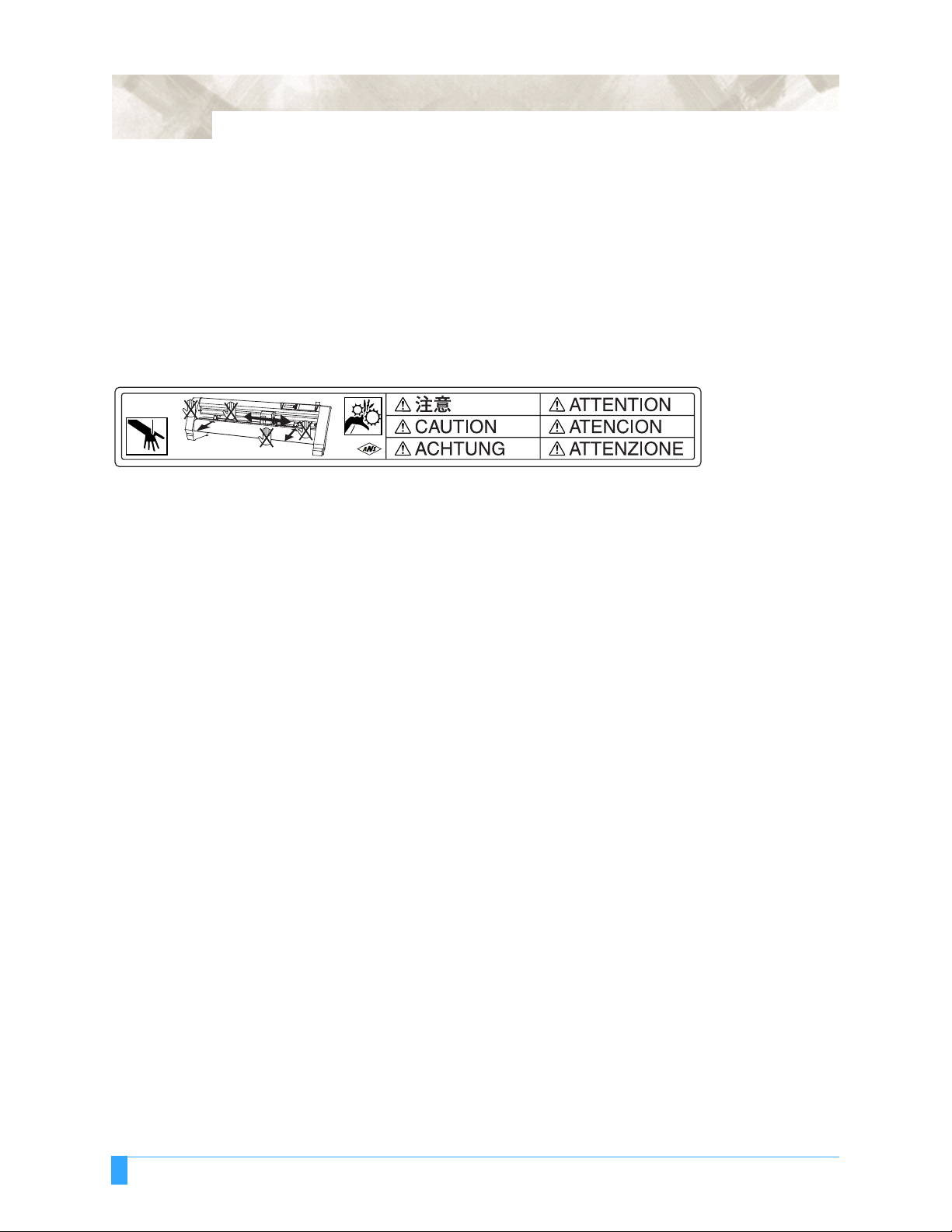
The machine's Caution Label is located on the top cover. Be sure to observe all the cautions on the label.
Daily Maintenance and Storage
Daily Maintena n ce
During the course of daily plotter operation, be sure to observe the following precautions:
(1) Never lubricate the mechanisms of the plotter.
(2) Clean the plotter's casing using a dry cloth that has been moistened in a neutral detergent diluted with water.
Never use thinner, benzene, alcohol, or similar solvents to clean the casings; they will damage the casing's finish.
(3) Cle an the cutting mat using a dry cloth. In c as e of st ubborn stains, use a cloth that has been moistened in alcohol
or in a neutral detergent diluted with water.
(4) Cle an the plo tter's p aper se nsors using a cloth mois tened in a neutra l deterge nt dilu ted wi th water. Never use thin-
ner, benzene, alcohol, or similar solvents to clean the sensors; cleaners such as these will damage the sensors.
Storing the Plotter
When your plotter is not in use, be sure to observe the following points:
(1) Remove the pen attached to the penholder
(2) Cover the plotter with a cloth to protect it from dust and dirt
(3) Do not store the plotter in direct sunlight or in high temperatures
Page 15

Chapter 1: Out of the Box
This chapter describes plotter nomenclature and how to
install your plotter.
Topics in this chapter
1.1 Checking the Co ntents
1.2 Nomenclature
1.3 Assembling the plotter
1.4 Attaching the FC7000 Basket (O ption)
1.5 Attaching a Cut ter Pen
1.6 Replacing th e Cross-Cutt er Unit
Page 16

1 - 2
1.1 Checking the Contents
After unpacking your plotter, check that all of the standard accessor ies shown
below are prese nt. If any acces sory is m issing, c ontact your sales representat ive
or the nearest Grapht ec dealer.
AC power cord
1 1 each
USB cable (3-m length)
User Guide CD-ROM
1
Contains:
User’s Manual (pdf)
Windows driver/Macintosh plug-in software
Cutter holder
(PHP32-CB09N)
1
Cutter blades
(CB09UA-2)
1
Media bracket
1
Quick Start Manual, Usage Precautions
1 of each
Water-based fibertip pen
1
Stand
(available as an option for the FC7000-75 model)
1
Base assembly x 2
Stand side bar x 2
Center bar x 1
Socket head cap screw x 20
Allen wrench x 1
Media stocker x 2
Stock roller x 2
M4 binding head screws x 8
Out of the Box: Checking the Contents
Page 17

1.2 Nomenclature
Front View
Power switch
Grit roller position guide
Cutting mat
Cutting groove
Pinch roller
Grit roller
Grit roller
Cross-cutter unit
Pen carriage
Media sensor
Media sensor
1 - 3
Pen holder
Pinch rollers
Control panel
Stand
Pen station
Power switch: ..............Used to turn the plotter on and off.
Control panel: ............ ..Used to access various p lotter f unction s.
Pinch rollers: ............. ..Rollers t hat push the medi a against the grit rollers.
Grit rollers: ..................Metallic rollers with a file-like surface that feed the media
back and forth.
Media sensor s: ............The front senso r is used to sen se t he le ading edge o f t he
media. The rear sens or is used to sen se the trai ling edge
of the media.
Pen carriage: ......... ......Mo ves the cutter -pen or plotti ng pen acr oss the media
during cutting or plo tting.
Pen holder: ..................Holds the cutter-pen or plotting pen and moves it up or
down.
Pen station (i nstalled on 2-pen m odels on ly):
The second pen is moun ted here.
Stand: .........................Used to make the plotter more portable and to free up
counter space
Grit roller position gui de:
Stickers on the front of the Y ra il and the rear side of the
top cover that show the position of eac h grit roller. Use
these alignment mar ks as an aid in locat ing the pinch rol l-
ers.
Cutting groove: ............Used when cross-cutting is performed.
Cross-cutter unit: .........Use d to perform cross -cutting of medi a so that the cut
length can be removed from th e roll.
Out of the Box: Nomenclature
Page 18

1 - 4
Rear View
Pinch roller hold-down force switching lever
AC line inlet
Media stocker
Stock rollers
Media set lever
USB interface connector
Media lock
RS-232C interface connector
Media set lever: .. ... .. ... .Us ed t o r ais e o r lo wer t he pi nch r ol ler s du ri ng th e lo ading
or unloading of medi a.
Pinch roller hold-dow n force switchi ng leve r:
Used to switch between the two pinch roller forces (strong
and weak).
AC line inlet: ................Inlet where the power cord is connected.
Media stocker: ......... ....Use d to carr y roll media and ensure its prop er rotatio n.
Stock rollers: ......... ......A media roll i s placed on the se roll ers.
Media lock: ..................Used to prevent the stock rollers from rotating when the
media roll has been pla ced on top of them . The media
lock ensures that the media is pulled straight out from the
roll.
USB interfac e connector:
Used to conne ct the p lotter to th e computer with a USB
interface cable.
Serial interface conn ector:
Used to conne ct the p lotter to the computer with an RS-
232 serial interf ace cable.
Out of the Box: Nomenclature
Page 19

1.3 Assembling the plotter
FC7000-75 (desktop model; stand not provided but is available as an option)
When the FC700 0-75 i s used w ithout a stand, t he medi a bracket is attach ed
directly to the plotter.
The media bracket is made up of the followi ng parts.
Stock roller x 2Media stocker x 2 M4 binding-head screw x 4
ATTACHING THE MEDIA STOCKERS
1 Fasten the media stocker to the le ft and right inside sur faces of the plotter unit,
using two M4 binding- head screws for each st ocker.
1 - 5
Front
Media stocker
Media stocker
2 Insert an M4 screw in the second hole from the front side of the plotter.
• Check that all of the scr ews used for fast ening have b een tigh tened. The media
may not be fed correctly if even one of the screws is loose.
• When installing the plotter, make sure that there are no objects in its vicinity.
Leave a clear space of at least 300 mm around the plotter.
• When the FC7000-75 is used without a stand, the max imum diameter of the
roll media that can be used is 160 mm.
Out of the Box: Assembling the plotter
Page 20

1 - 6
FC7000-100/130/160 (stand provided)
Assemble the stand, attac h the media brack et to the stand, and the n mount the
plotter on t he stand.
The stand and the media bracke t are made up of th e following parts.
Base assembly x 2 Allen wrench
Media stocker x 2
Center bar x 1Stand side bar x 2 Socket head cap screw
Stock roller x 2
(for M5 screws) x 1
(M5) x 20
ASS EMBLING THE STA N D
The mounting direc tion is different fo r the front lo ading and the rear loading
models.
<Front loading>
Out of the Box: Assembling the plotter
<Rear loading>
Page 21

1 - 7
1 Assemble the left and ri gh t stand sides . Fa ste n a bas e asse mbl y to eac h of the
stand side bars with fo ur socket head cap scr ews, using the Al len wrench.
Socket head
cap screws
Base assembly
Stand side bar
Stand side bar
Assemble the sta nd so that the front and rear lengths of th e base assem bly are
the same for both the left and right stand sides.
2 Loosely faste n the c enter bar to t he left and right stand sid es with four socke t
head cap screws (two on each side), using the Allen wrench.
Socket head
cap screws
Center bar
Socket head
cap screws
Stand sides
3 Attach a media s tocker t o each of the left and r ig ht stand si des w ith tw o sock et
head cap screws, using the Allen wrench. Mount the media stockers so that
each one protrudes di rectly above t he longer of the tw o base assembly
lengths.
Media stocker
Socket head cap screws
Media stocker
Stand sides
Base assembly
Out of the Box: Assembling the plotter
Page 22

1 - 8
4 Mount the plotte r on the stand by inserti ng the positio ning pins on the stan d
into the position ing holes on the underside of th e plotter. Fasten with four
socket head cap scr ews (two on each side), using the Allen wrench.The cutting
plotter mount ing dire ction is differ ent for th e front loading and the rea r loadin g
models.
<Front loading>
Socket head
cap screws
Positioning pin hole
<Rear loading>
Socket head
Positioning pin
Caster stoppers
cap screws
5 Tighten the socket he ad cap s crews loo sely fas tened i n Step 2.
• Check that all of the scr ews used for fast ening have b een tigh tened. The media
may not be fed correctly if even one of the screws is loose.
• When installing the plotter, make sure that there are no objects in its vicinity.
Leave a clear space of at least 300 mm around the plotter.
Out of the Box: Assembling the plotter
Page 23

Mounting the stock rollers
Insert the stock ro llers into the slots on the media stocker.
1 - 9
<Front loading>
Stock rollers
<Rear loading>
Front
Stock rollers
Out of the Box: Assembling the plotter
Page 24

1 - 10
1.4 Attaching the FC7000 Basket (Option)
The FC7000 Basket box contains one basket ho lder assembly (on e front basket
tube and one rear basket tube inserted int o two tube brack ets), one cloth ba sket,
and a screw/wrench set.
1 Attach one of the two tube br ackets on the basket holder assembl y to the left
side of the stand with two s ocket head cap scr ews, usin g the Allen w rench.
Repeat this step wit h the other si de.
Socket head
cap screw
Socket head
cap screw
Stand
Basket holder assembly
2 Drape the mid dle sect ion of t he cloth basket over the stand's ce nter b ar, and
then snap the middle section of the cloth basket around the center bar. Snap
the front edg e of t he clot h basket around the fr ont ba sket tube, and t hen snap
the rear edge of the cloth basket around the rear basket tube.
Side view
Holder snap
Front
Center bar
Cloth basket
Out of the Box: Attaching the FC7000 Basket (Option)
Cloth basket
Separate into front and rear baskets,
with the center bar as the center point
Page 25

1.5 Attaching a Cutter Pen
When mounting t he cutter pen in the pen holder, push the pen all the way into t he
holder until its flang e contacts the upper part of the holder and then tighten th e
screw firmly. To prevent injury, avoid touching the pen immediately after the cutting
plotter is turned on or whenever the pe n is moving.
1 Loosen the pen holder screw.
2 While pushing the pen hol der in the upwa rd direc tion, push th e pen al l the w ay
into the holder un til its flange contacts th e upper part of th e holder.
1 - 11
When pushing the pen holder with your fingers, the blade tip may be
protruding. Take care not to cut your fingers.
Upper part of pen holder
Flange
3 Make sure that the pe n bracket is enga ged on the pen’s flang e, and then
tighten the screw.
Flange
Bracket to hold pen
Out of the Box: Attaching a Cutter Pen
Page 26

1 - 12
Attaching a Pen to the Two-Pen Holder (Option)
The two-pen holder is a factory-i nstalled option, an d cannot be ret rofitted.
1 Loosen the pen holder screw.
2 While pushing the pen hol der in the upwa rd direc tion, push th e pen al l the w ay
into the holder un til its flange contacts th e upper part of th e holder.
When you push the pen holder with your fingers, the blade tip may be
protruding. Take care not to cut your fingers.
Flange
Upper part of pen holder
3 Make sure that the pe n bracket is enga ged on the pen’s flang e, and then
tighten the screw.
Flange
Bracket to hold pen
Out of the Box: Attaching a Cutter Pen
Page 27

Attaching a Plotting Pen to the Pen Station
Follow the procedur e below to repla ce the cross-cu tter unit th at is used to cut the
media after the plottin g or cutting ope ration has been com pleted.
1 Open the pen-hold mechanism on the pen station, and then attach a pen.
2 Make sure that the bracket of the pen station is engag ed in the upper groove of
the pen.
1 - 13
3 Close the pen-hold mechanism on the pen station to hold the pen in place.
• Do not leave a pen attached to the pen station for a long period of time, as the
pen tip will dry up and make it unusable.
• To store the pen, remove it from the pen station and replace its protective cap.
Out of the Box: Attaching a Cutter Pen
Page 28

1 - 14
1.6 Replacing the Cross-Cutter Unit
1 Check that the power switch is turned off (the " " side is pressed down).
2 Remove the screw holding the cross-cutter unit in place, and then remove the
cross-cutter unit.
Cross-cutter unit
3 Remove the protective cover from the replacement cross-cutter unit. Be sure
to remove the protect ive cover whi le holding the part of the unit shown in the
figure below.
Protective cover
Out of the Box: Replacing the Cross-Cutter Unit
Page 29

1 - 15
4 Attach the replace ment cross-cutt er unit, and tigh ten the screw to ho ld it in
place.
Cross-cutter unit
WARNING: The cross-cutter unit uses a very sharp blade. Take care not to cut your-
self on the blade.
Out of the Box: Replacing the Cross-Cutter Unit
Page 30

1 - 16
Out of the Box: Replacing the Cross-Cutter Unit
Page 31

Chapter 2: Cutter Blades
and Cutter Pens
This chapter describes the different cutter blades and cutter
pens.
Topics in this chapter
2.1 Blade Ap plicati on and F eatures
2.2 Cutter Pen Nome nclature
2.3 Replacing the C utter Blad e
2.4 Adjustin g the Blade L ength
Page 32
2 - 2
2.1 Blade Application and Features
Individual cutter bl ades have a variety of features. Sel ect the optimal cutte r blade
to suit the medium to be cut.
Blade part
no. and type Diameter
CB09UA 0.9 mm PHP32-CB09N Standard blade for cutting color adhesive media. Suit-
CB15U 1.5 mm PHP32-CB15N For cutting media which is too thick for the CB09UA
CB15UA 1.5 mm PHP32-CB15N For cutting high intensity reflective media.
CB15UB 1.5 mm PHP32-CB15N For cutting small characters on mono-vinyl chloride
CB15U-K30 1.5 mm PHP32-CB15N
Plunger part
no. Applications and features
able for cutting m edia u p to 0.25 mm th ick. M aximum cutting distance of approximately 4000 m.
blade to handle. Sui tab le for c utting med ia f rom 0.2 5 mm
to 0.5 mm thick.
media. Suitable for cutting small size characters that are
less than 10mm.
For cutting sandblast rubber. The sharply angled point
or
PHP32-CB15
provides a longer cutting edge. Suitable for cutting material from 0.05 mm to 1.5 mm thick.
WARNING: To avoid bodily injury, handle the cutter blade with care.
Cutter Blades and Cutter Pens: Blade Application and Features
Page 33

2.2 Cutter Pen Nomenclature
The plotter cuts using a cutter blade mount ed in a cutter-pe n plunger. There are
two different cutter- pen plunger s to suit the diamet er of the cutter bl ade to be
mounted (the 0.9- mm cutter- pen pl unger is p rovid ed as a standar d access ory) . Be
sure to mount the cutter blade in the corresponding cutter-pen plunger.
2 - 3
Cutter blade
Plunger cap
Plunger
Blade-length adjustment knob
(Blue: For 0.9-mm-diameter blades)
(Red: For 1.5-mm-diameter blades)
WARNING: To avoid bodily injury, handle cutter blades with care.
Cutter Blades and Cutter Pens: Cutter Pen Nomenclature
Page 34

2 - 4
2.3 Replacing th e Cu tt er Bla de
Structure of Cutter Pen
1.5-mm-diameter cutter pen
Blade-length adjustment knob
Plunger cap
cross-section
Replacing the Cutter Blade
While referrin g the above figu res, f ollow the pr ocedu re be low to repl ace t he cutt er
blade.
1 Turn the blade-length adjus tment knob in th e direction in dicated by the ar row
to retract the blad e into the plung er.
(red)
Plunger
1.5-mm-dia. blades
Plunger-cap
0.9-mm-diameter cutter pen
Blade-length adjustment knob
(blue)
Plunger
0.9-mm-dia. blades
Spring
Plunger-cap
Plunger-cap
cross-section
2 Turn the plunger cap in the count er-clockwise di rection to remo ve it from the
plunger.
3 Remove the b lade from inside the pl unger c ap.
4 Remove a new blade fro m its pack. Insert t he new blad e into t he hole pro vided
in the plunger cap.
5 With the blade in serted into the plung er cap, screw on the plunge r from above .
Cutter Blades and Cutter Pens: Replacing the Cutter Blade
Page 35

2.4 Adjusting th e Bla de Le n g th
WARNING: To avoid bodily injury, handle cutter blades with care. Make sure to
correctly adjust the blade leng th. If the blade length is too long for the
thickness of the media being used, you may cut through the cutting mat
and damage your plotter.
1 Adjust the blade l ength b y turni ng the bl ade-le ngth ad justment knob. Turn the
knob in direction "A" to extend the blade, or in direc tion "B" to retr act the
blade. When the knob is turned by one scale unit, the blade moves approxi-
mately 0.1 mm. One full turn of the knob moves the bl ade approxima tely 0.5
mm.
The blade moves approximately
0.1 mm per scale unit
2 - 5
B
A
2 First align the blade tip with the tip of the cutter pen, and then extend the blade
from that position t o suit the thickn ess of the media to be cut.
3 Assuming that the medi um thickness is "t," as shown in the fi gure below, the
blade length "l" sho uld be equal to or slightly greate r than "t." Make sure that
"l" is never greater th an the comb ined th icknes s of the medi um and its backi ng
sheet. If it is not possible to accurately determine the medium thickness, adjust
the blade length by gradu ally inc reasi ng it until onl y traces of the blade ap pear
on the backing sheet after a cutting test is conducted.
Medium
Backing sheet
t
l
Cutter Blades and Cutter Pens: Adjusting the Blade Length
Page 36

2 - 6
Cutter Blades and Cutter Pens: Adjusting the Blade Length
Page 37

Chapter 3: Preparing to Cut
This chapter describes how to use the control panel, load
the media, select and install the appropriate cutting tools,
and to achieve the best cutting results.
Topics in this chapter
3.1 Control Panel
3.2 Selecting a Fu nction Menu
3.3 Connecti ng to y our Com puter
3.4 Turning on the P ower
3.5 Loading Media
3.6 Aligning th e Pinch Rolle rs
3.7 Selecting the Med ia Type
Page 38

3 - 2
3.1 Control Panel
Indicator Lamps
POWER lamp: .........Remains lit (green) while the plotter is on.
PROMPT lamp:....... .Li ghts red when the cutti ng data goes beyond t he effective
Function Keys
These four keys [F1, F2, F3 and F4] have fu nctions which chan ge as each menu
changes. Depending on the menu being disp layed, these keys ar e used to:
cutting area.
Position Keys
F1 (FORCE) key: .....When t he FC700 0 is in ME NU mode , press t he F1 key to
select a function. When the FC7000 is onli ne, press F1 to
select the Conditio n numbers 1 and 5. After pre ssing the
CONDITIONS key, use F1 to adjust the cutting/pen FORCE.
F2 (SPEED) key: .....When the FC700 0 is in MENU mode , press the F2 key to
select a function. When the FC7000 is onl ine, press F2 t o
select the Conditio n numbers 2 and 6. After pre ssing the
CONDITIONS key, use F2 to adjust the cutting SPEED.
F3 (QUALITY) k ey: .. When the F C7000 is in MENU mo de, pr ess the F3 key t o
select a function. When the FC7000 is onl ine, press F3 t o
select the Conditio n numbers 3 and 7. After pre ssing the
CONDITIONS key, use F3 to adjust the cutting QUALITY.
F4 (OFFSET) key:. ...W hen the FC7000 is in MEN U mode, press the F4 key t o
select a function. When the FC7000 is onli ne, press F4
select the Conditio n numbers 4 and 8. After pre ssing the
CONDITIONS key, use F4 to adjust the cutting OFFSET.
POSITION keys ....... Depending on t he operatin g status of the FC7000 , the
POSITION keys have the followin g funct ions.
When the FC700 0 is in the MENU mode, use the POSITION
keys to change the set ting val ues sho wn in th e va rious men u
displays. The POSITION keys are also u sed t o move th e p en
carriage and t he media . If a P OSITION key is p ressed onc e,
the pen carriage moves th e length of the step specified in
Section 5.9, “Using th e MOVE STEP Function ”. If t he key is
held down, the movement is continuous. To spe ed up the
movement of the pen carr iage, press the NEXT key together
with a POSITION key.
Preparing to Cut: Con trol Panel
Page 39

Menu Keys
3 - 3
CONDITIONS key: ...Press CONDITIONS to change the pen conditions shown on
the FC7000 dis play panel.
HOLD key:...............Press HOLD to temporarily suspend cutting or plotting. While
the cutting or plott ing opera tion is suspende d, the me dia set
lever can be lowered to enab le skew ed media to be r eset i f
necessary.
MENU key: ..............Press MENU to access the MENU mode. When this key is
pressed, the MENU mode is ac cessed and the green LED
lights. Press it again to cancel MENU m ode. The green LE D
goes out. Use this key to set the various menu functions. If
data is received after the MENU key has been pressed, that
data is temporari ly stored in the plotter 's buffer.
COPY key:...............Press COPY to repeat the cutting operation defined by the
data in the plotter's bu ffer.
HOME/VIEW key:.....Press HOME/VIEW to move the pen carriage to the standby
position. Press it again to move the pen carriage to the origin
point. Press it one mo re time to r eturn t he pe n carr iage t o its
former position .
NEXT key:...............When the FC7000 is in MENU mode, press NEXT to move to
the next menu page .
TEST key: ...............Press TEST to run a cutting test to check whether the cur-
rently-select ed cutting cond itions are compatib le with the
media loaded.
AXIS/R.M.S. key:.....Press AXIS/R.M.S. to initiate automatic reading of the regis-
tration marks. If Off has been sel ected for the regist ration
mark mode, th is key is used t o perf orm axis a lignment .
ORIGIN key:............Press ORIGIN to move the origin point. To reset the FC7000,
press ORIGIN and ENTE R together when th e initial MENU
mode screen is displayed.
ENTER key:.............Press ENTER to register your setting after setting a function.
To reset the FC7000, press ENTER and ORIGIN together
when the INI TIAL M ENU mode screen is d isplayed. The c utting area can a lso be di splayed b y pressing the EN TER key
in Ready status.
Preparing to Cut: Control Panel
Page 40

3 - 4
3.2 Selecting a Function Menu
When the FC7000 is in MENU mode
When the plott er is i n MENU mod e (the MENU l amp is l it), eac h of the functio ns
listed below in the “ Function Selecti on” column can be accessed by pre ssing th e
NEXT key until the desi red menu appea rs and then pre ssing the select key indicated by a box.
Page Main menu Sub menu
NEXT
ASSIGN PEN (2-pen model only)
CROSS CUT
PRE FEED
MOVE STEP
NEXT
NEXT
INTERFACE
AREA PARAMETERS
FUNCTION 1
FUNCTION 2
PEN UP/DOWN
BACKGROUND
SETTINGS
F1
FORCE
F2
SPEED
F3
QUALITY
F4
OFFSET
F1
FORCE
F2
SPEED
STEP SIZE (GP-GL only)
RS-232C
COMMAND
ORIGIN (HP-GL only)
AREA
EXPAND
PAGE LENGTH
PREF. LINE TYPE
ROTATE
MIRROR
SCALE
DATA SORTING
AXIS ALIGNMENT
AUTO FEED
TANGENT EMULATION
OPTION 1
OPTION 2
Preparing to Cut: Se lecting a Function Menu
F3
QUALITY
F4
OFFSET
PEN UP SPEED
OFFSET ANGLE
OFFSET FORCE
STEP PASS
PEN OFFSET ADJ. (2-pen model only)
INITIAL DOWN FORCE
DISTANCE ADJUST
TEST
Page 41

When the power is turned on without any media loaded
If the power is turned on witho ut any med ia loade d in th e plo tt er, the initial menu is
displayed on t he LCD. T he init ial menu c onfigur ation is as foll ows.
Main menu Sub menu
3 - 5
Initial menu
F4
OFFSET
AUTO REG. MARK
AUTO PRE FEED
INITIAL FEED SPEED
INTERFACE
OFFSET
F4
STEP SIZE (GP-GL only)
RS-232C
COMMAND
Preparing to Cut: Selecting a Function Menu
Page 42

3 - 6
3.3 Connecting to your Computer
An interface cable is use d to connect the plotter to a computer. The plotter can be
connected to a comput er via the USB or seri al (RS-232C) port. Selec t which port
to use according to the requirements of your application software and/or which of
your computer's int erface ports are ava ilable for use .
Use a USB cable or serial cable in accordance with the connection method chosen. Obtain a Graphtec-app roved interface ca ble that is compatible with the interface port.
1 Make sure the power switch is turned off (the " " side is pressed down).
2 Connect one end of the cable to the FC7000 and the other end to the computer
port.
RS-232 inter face co nnecti on USB interfac e conn ection
Preparing to Cut: Connecting to your Computer
Page 43

3.4 Turning on the Power
1 Make sure tha t the power swi tch is t urned off (the " " side is presse d down) .
2 Connect one end of the provided power cord to the FC7000 AC line inlet and
the other end to an electrical socket of the rated supply voltage. Make sure
that the FC7000 is grounded.
3 - 7
3 Turn on the FC7000 by pressing th e "|" side of the swit ch. The control panel
POWER lamp lights.
4 If media has not been loaded, the f irmware version number i s displa yed, fo l-
lowed by a prompt to load media.
LOAD MEDIA!
INITIAL MENU>
(The initial feed spe ed setting, inter face settings and other parameter setting s
can be made h ere).
Preparing to Cut: Turning on the Power
Page 44

3 - 8
If media has alread y been loaded, the fo llowing menu appears.
Rear Loading Front Loading
ROLL 1 REAR SET>
ROLL 2 REAR SET>
SHEET>
[NEXT]
←—→
ROLL 1 FRONT SET>
ROLL 2 FRONT SET>
SHEET>
After the Ready status is d isplayed, raise the media set lever to secu re the
loaded media. The foll owing menu app ears.
Rear Loading Front Loading
ROLL 1 REAR SET>
ROLL 2 REAR SET>
SHEET>
CONTINUE>
[NEXT]
←—→
ROLL 1 FRONT SET>
ROLL 2 FRONT SET>
SHEET>
CONTINUE>
The loading method screen (Rear or Front) that is first displayed is the screen
that was last used.
5 Select the media ty pe to suit the med ia used. See Secti on 3.5, "Loadi ng
Media" for instruct ions on how to load med ia.
When to select ROLL 1 REAR SET or ROLL 1 FRONT SET
Select ROLL-1 to beg in cutting or pl otting from the leading edge. ROLL-1
detects the width and leadin g edge of roll media. Press the F1 key to select
ROLL-1 REAR SET or ROLL 1 FRONT SET.
When to select ROLL 2 REAR SET or ROLL 2 FRONT SET
Select ROLL-2 to beg in cutting or pl otting at a point beyond the leadi ng edge.
ROLL-2 detects only th e width of roll media. Pr ess the F2 key to sel ect ROLL-
2 REAR SET or ROLL 2 FRONT SET.
When to select S HEET
Select SHEET when a cut shee t has been loade d in th e plott er. SHEET detects
the leading edge, t he trail ing edg e, and the width of the sheet. Press t he F3
key to select SHEET.
When to select C ONTINUE
The CONTINUE funct ion enables th e continued use of the plotting ar ea, pen
position and ori gin posit ion that we re specif ied before t he media set lever was
lowered. If the cur rent media is the sam e size as the last medi a that was
loaded, the plott er does not detec t the media's edges.
6 After selecting th e media type, spe cify the blade/pe n type and the cut ting/plot -
ting conditions for the selected media type, and then perform cutting or plot-
ting.
Preparing to Cut: T urning on the Power
Page 45

3.5 Loading Media
Both roll media and shee t media can be used w ith the FC7000. Load the media
according to th e instruct ions gi ven for e ach typ e.
The FC7000-100/130 model with three pinch rollers is used for the explanations
in this section. The FC7000-160 model has four pinch rollers, whereas the
FC7000-75 model has only two pinch r ollers.
Loading Roll Media (Rear Loading)
1 Lower the media set lev er to raise the pin ch rollers.
3 - 9
Pinch roller
2 Place the media r oll o n the roll med ia sto cker. Load the media in t he plo tter a s
shown. Pass the leadi ng edge o from th e bac k of the pl ott er so it emer ge s fr om
the front.
3 Press the media lock t o engag e it, and then pull th e leadi ng edge out o f the
front of the plotter so that it completely covers the media sensor.
Media lock
Media sensor
Preparing to Cut: Loading Media
Page 46

3 - 10
4 Pull the media taut to ma ke sure tha t there is no slack in the co nveyan ce path,
and then raise the media set lever to lower the pinch rollers. Release the
media lock.
Loading Roll Media (Front Loading)
1 Lower the media set lev er to raise the pin ch rollers.
Media lock
Pinch roller
2 Place the media r oll o n the roll med ia sto cker. Load the media in t he plo tter a s
shown. Pass the leadi ng edge from th e front of the plot ter so it emerges f rom
the back.
Preparing to Cut: Loading Media
Page 47

3 - 11
3 Press the media lock t o engag e it, and then pull th e leadi ng edge out o f the
back of the plotter so th at it complete ly covers the medi a sensor.
Media lock
Media sensor
4 Pull the media taut to ma ke sure tha t there is no slack in the co nveyan ce path,
and then raise the media set lever to lower the pinch rollers. Release the
media lock.
Media lock
Loading Sheet Media
1 Lower the media set lev er to raise the pin ch rollers.
Pinch roller
Preparing to Cut: Loading Media
Page 48

3 - 12
2 Pass the leading edge of the sheet from the rear of the plotter so that it
emerges from the front, making sure that is completely covers the media sen-
sor.
Media sensor
3 Pull the media taut to ma ke sure tha t there is no slack in the co nveyan ce path,
and then raise the media set lever to lower the pinch rollers. If you align the
right edge of the sh eet wi th the g uides on the p laten, the she et can be load ed
so that it is
straight.
Preparing to Cut: Loading Media
Media
Align with
these holes
Page 49

3.6 Aligning the Pinch Rollers
Position the l eft- and right pinc h roller s to cor respond w ith the width of th e media.
Adjust the pinch rollers so that they are positioned above both the media and the
grit rollers. Posit ion the pinch ro llers within th e grit roller pot ition sticker s ensures
that they are above the grit roller s.
3 - 13
Grid roller potition sticker
NG
OK
NG
OK
Standby Position
CAUTION: To move the pinch rollers, the media set lever must be in the lowered position.
With the FC7000-100/130/160 models, the number of pinch rollers required to hold
down the media vari es according to the width of the loade d media. Be sure to
move a pinch roller that is not used to the standb y position so tha t it does not
affect the cutt ing or p lotting operat ion.
Standby position
Preparing to Cut: Aligning the Pinch Rolle rs
Page 50

3 - 14
When Feeding Long-axis Media (at least 2 meters)
Position the pinch rol lers at least 15 mm inside the edge s of the media.
Pinch rollers
When the Media Width is 100 to 160 mm
Position the two rig ht-hand pinc h rollers so that they are above th e long grit rolle r
at the right edge of the plotter whe n the plotter is vie wed from the front. Positi on
the media so t hat its left edge is ali gned with the l eft edge of the grit r oller, and
then position the pinch rol le rs over both edg es. Move an y pinc h roll er s that ar e no t
used to the standby posit ion.
Media sensor
Media
OK
CAUTION: • The media must be at least 125 mm in length.
• The media must always be positioned over the media sensor.
Pinch rollers
Grit roller
Media
15mm15mm
When the Media Width is 160 to 540 mm
Position the two rig ht-hand pinch r ollers when the plotte r is vi ewed fr om the fr ont
so that they are at the edg es of the media. Make sur e that the pinc h rollers are
both positioned ov er grit roll ers. Move any pinc h rollers tha t are not used to the
standby position.
Pinch roller
Media
OK
CAUTION: The media must always be positioned over the media sensor.
Preparing to Cut: Aligning the Pinch Rolle rs
Grit roller
Pinch roller
Media sensor
Page 51

When the Media Width Exceeds 540 mm
Position the three right-hand pinch rollers when th e plotter is viewed from the front
so that the left and right pi nch rollers are at the edges and the middle pinch rol ler
in the center o f the media. Make sure that al l the pinc h rollers are posi tioned o ver
grit rollers. Mo ve any pinch rolle rs that are no t used to the standby position.
If you wish to use all fo ur of the FC7000 -160 pinch rol lers, position the two outermost pinch rollers at th e edges of the media and the other two pinch r ollers in
between, making sure that the pinch rol lers are all spaced eq ually, and that each
pinch roller is posit ioned over a grit roller.
Pinch roller
Pinch roller
OK NG
Grit roller
Media
sensor
3 - 15
Pinch roller
NG
CAUTION: The media must always be positioned over the media sensor.
Changing the Hold-down Force
The pinch roller hold- down force must be set to suit the w idth and type of the
loaded media
SWITCHING B ETWEEN THE STRO NG AND WEAK SETTINGS
Use the hold-down force switching lever located at the back of each pinch roller to
change the hold-do wn force. Rais e the lever to decr ease the hold- down force
(Weak), and lower the lev er the increase th e hold-down fo rce (Strong).
NG
Strong hold-down forceWeak hold-down force
Preparing to Cut: Aligning the Pinch Rolle rs
Page 52

3 - 16
OLD-DOWN FORCE ASSIGNMENTS
H
Use the Strong setting for the pi nch rollers use d to hold down t he edges of the
media. Always use the Weak setting for the pinch roller(s) between the two outside
rollers.
When two pinch rollers are used
OK
Strong Strong Weak Weak
NG
Weak
Strong Strong
When three pinch rollers are used
Weak
OK
Strong Weak Strong
Weak Weak Weak
NG
Strong Strong Strong
Weak Strong Weak Weak Strong Strong
When four pinc h rollers are us ed
OK
NG
All other combinations
StrongStrong Weak
Weak Weak Strong
Strong Weak Weak StrongWeak Weak Weak Weak
WeakWeakStrong
Preparing to Cut: Aligning the Pinch Rolle rs
Page 53

3.7 Selecting the Media Type
1 If you have already loaded the media, the MED IA TYPE men u appears . Select
the media typ e to s uit the loaded media.
Rear Loading Front Loading
3 - 17
ROLL 1 REAR SET>
ROLL 2 REAR SET>
SHEET>
The loading method screen (Rear or Front) that is first displayed is the screen
that was last used.
Select the media ty pe.
When to press the F1 ke y to sel ect ROLL 1 REAR SET/ ROLL 1 FRONT S ET
Press the F1 key when you ha ve loaded a roll of med ia and you wish to start
cutting or plotting from the leading edge. The width and leading edge of the roll
media are dete cted. T he pe n carri age mo ves to the or igin p oint after th e ini tial-
ization routine has been execute d.
When to press the F2 ke y to sel ect ROLL 2 REAR SET/ ROLL 2 FRONT S ET
Press the F2 key when you ha ve loaded a roll of med ia and you wish to start
cutting or plottin g from a point bey ond the leadin g edge. Only the width of the
roll media is detected.
If the F1 or F2 key is pressed, the following prompt appea rs. Confirm th at the
media lock has been r eleased, a nd then p ress t he ENTER key.
PRESS ENTER KEY
AFTER RELEASING
MEDIA LOCK
[NEXT]
←—→
ROLL 1 FRONT SET>
ROLL 2 FRONT SET>
SHEET>
Release media lock
When to press th e F3 key to sele ct SHEET
Press the F3 k ey wh en a cu t s hee t has bee n l oa ded . T he le ad ing ed ge, tra il ing
edge, and width of the sheet are dete cted.
When to press th e F4 key to sele ct CONTINU E
The CONTINUE funct ion enables th e continued use of the plotting ar ea, pen
position and ori gin posit ion that we re specif ied before t he media set lever was
lowered. If the cur rent media is the sam e size as the last medi a that was
loaded, the plott er does not detec t the media's edges. (The CONT INUE menu
parameter appears when the media set lever is raised and then lowered again
after media was previous ly loaded.)
Preparing to Cut: Selecting the Media Type
Page 54

3 - 18
2 After the media is detecte d, the followin g screens are displa yed in succession.
"ROTATE" OFF
"MIRROR" ON
↓
CUT AREA
X=*****mm Y=*****mm
↓
CONDITION 1 12
20
READY 4
Pen
The plotter is now ready to receive data f or cutting or plotting. If th e interface or
command settings have not been made, make these settings before sending the
data. If the settings have been made, pen adjustme nt is perfor med. When the pen
adjustments have b een ma de, t he pl ot te r is re ady t o start cu tt in g. Send t he cutti ng
or plotting data from the application software.
Preparing to Cut: Selecting the Media Type
Page 55

Chapter 4: Pen Setting
Conditions
This chapter describes how to make the blade type settings,
and the FORCE, SPEED, OFFSET and QUALITY settings to
ensure the optimal pen condit ions before performing cutt ing
or plotting.
Topics in this chapter
4.1 Pen Condition s
4.2 Selecting Cut ter-Pen Co ndition Set ting Areas
4.3 Setting the Cutter-pen Conditions
4.4 Running Cuttin g Tests
4.5 Adju sting the B lade Length
Page 56

4-2
4.1 Pen Conditions
Before cutting media, t he foll owing fi ve cutter -pen condi tions m ust be specifie d.
(1) Cutter-blade length:..... Adjust the blade len gth by refer ring to the me dia thick-
ness table below.For details on adjusting the blade
length, see Secti on 2.4, "Adju sting and Mount ing the
Cutter Pen".
(2) FORCE: ...................... Set the FORCE by referring to the table below.
(3) SPEED: ...................... Set the SPEED by referring to the table below.
(4) QUALITY:.................... Set the QUALITY by referring to the table below.
(5) OFFSET: ..................... Set to suit the cutter blade being used.
Optimal Cutting Conditions for Each Media Type
Media type Thickness (mm) Blade used Force Speed QUALITY
Film for outdoor use 0.05-0.08 CB09UA 10-14 less than 30 3-4
Film for decorative use 0.08-0.1 CB09UA 14-17 less than 30 3-4
Film for outdoor use 0.05-0.08 CB15UB 10-14 less than 20 1
Transparent or semi-
transparent film
Reflective film 0.08-0.1 CB09UA 14-20 less than 30 3-4
Fluorescent film 0.20-0.25 CB09UA, CB15U 20-24 10-20 2-3
Thick materials 0.5-0.1 CB15U-K30 17-24 5-15 2-3
High-intensity reflective film 0.25-0.3 CB15UA 35-24 5-40 1
Paint protection film CB09UA 14-35 30 4
0.08-0.1 CB09UA 14-20 less than 30 3-4
Blade Part No s., Dis played B lade Types, and CUTT ER OFFS ET Values
LCD panel indication
Blade part
Blade material/too l
Supersteel blades CB09UA CB09Ux 0 ±5 18
Other OTHER 1 1-45 1
Pen PEN N/A N/A 0
Pouncing tool POUNCE 1 1-99 1
Light Pointer LIGHT POINTER N/A N/A 0
When a blade type has bee n selected, th e OFFSET is automati cally adjusted by
±5 with respect to the de fa ul t cut ter offset valu e fo r that bla de type . Sel ect OTHER
to use settings ot he r tha n t hos e di spl aye d for har d-t o- cut media . S el ect PE N w he n
a plotting pen has been mounted in the plotter. Select POUNCE when a pouncing
tool has been mounted i n the plotter.
Pen Setting Condition s: Pen Condition s
no.
CB15-10U CB15-10Ux 0 ±5 18
CB15U CB15Ux 0 ±5 28
CB15UB CB15UBx 0 ±5 5
CB15U-K30 CB15U-K30x 0 ±5 28
Specifiable
range
Initial
OFFSET
valueBlade (tool) type Default value
Page 57

Reference Pen Conditions for Plotting Pens
Pen type Part no. FO RCE SPEED (cm/s) QUALITY
Water-based fiber-t ip pen KF550 Series 10-12 30 4
Disposable ink pen SD pens (PHP33-INK) 7-8 20 2
Oil-based ballpoint pen KB140 Series (PHP31-BALL) 21, 22 60 4
To p rolong th e pen life, s et the FORCE to the lo west s etting, and set the S PEED
after checking to confir m that there are no faint lines or othe r problems durin g
plotting.
• If the SPEED and QUALITY settings are set to high values, the cut/plotted
results will have a coarser finish, but the overall cutting/plotting time will be
reduced. In particular, when using wide media, the media may not be fed
smoothly during the cutting operation, thus preventing high quality results from
being obtained. In this case, set the SPEED and QUALITY settings to low
values.
• If the SPEED and QUALITY settings are set to low values, the cut/plotted
results will have a fin er fin is h, but th e over al l cut ting /pl otti ng ti me will be longer.
PRECAU TIONS TO OBSERVE WHEN CUT TING HIGH-INTENSITY REFLECTIVE FILM
The backing sheet used with high-intensity reflective film is very soft, and needs to
be reinforced. Attach strips of media to the reverse side of the backing sheet at the
locations where t he backin g sheet wil l come int o contact w ith the gr it roller s. (The
media we recommend that you use for rein forcement ar e the cutting s heets
supplied by Naka gawa Che mical, Inc ., or si milar.)
4-3
HOW TO IMPROVE WEEDABILITY
We recommend that you observe the following poi nts to improve th e weedability of
color marking film.
• Select the corre ct blad e for the ap plicatio n
CB09UA: Use this blade for general color mar king film appli cations.
CB15B: Use this blade for cutting small text (with a height th at is less than 10
mm) on color marki ng film.
• Use blad es that a re not worn.
If the blade is worn, it will not cle anly an d the cut r esults w ill be diffic ult to weed.
• Adjust the blade-le ngth a nd FORCE settin gs unti l only traces of the bl ade are
left on the b acking sheet .
Specify a FORCE value that is as low as possibl e, but that still le aves faint
traces on the backing she et.
• Set the SPEED and QUALITY values as low as possible.
• Weed the cut results r ight aft er cuttin g has b een comp leted.
If time is allowed to elapse, adhesive along the cut edges will cause the edges
to stick toget her.
• Select medi a with good weedabili ty.
Recommended film t ypes: 3M Scotchcal Electro Cut, 3M Scotchcal Master Cut
Weeding refers to the remov al of un wan ted areas of vinyl from the back ground
after the media has been cut.
Pen Setting Conditi ons: Pen Conditio ns
Page 58

4-4
4.2 Selecting Cutter-Pen Condition Setting Areas
The cutter-pen condi ti ons can be stor ed in eigh t setti ng ar ea s number ed "1" to "8".
To set the cutter-pen conditions, first select the setting area (condition number).
Moreover, switching between th e setting areas ena bles up to eight predefined
media types to be selected easily.
SELECTION METHOD
1 Press one of the F1 to F4 keys to select a group of previously-stored condition
settings.
2 If the F1 key is pressed when CONDITION 1 h as been se lected, the display
changes to CONDIT ION 5. If a condition nu mber other th an 1 was selected,
CONDITION 1 will be display ed when the F1 key is pr essed. I n the s ame way,
press F2 to select condition number s 2 and 6, F3 to select co ndition numbers 3
and 7, and F4 to select condition numbers 4 and 8.
3 The selected cutt er-pen conditi on settings will be used for the cut ting
operation.
Pen Setting Conditions: Selecting Cutter-Pen Con dition Setting Areas
Page 59

4.3 Setting the Cutter-pen Conditions
This section d escribes ho w to sel ect a b lade type and ho w to make the F ORCE,
SPEED, OFFSET and QUALITY settings.
To Change the FORCE
The FORCE paramete r sets t he cut ting fo rce ap pl ied duri ng a cu tt in g oper at io n, or
the plotting force during a plot ting oper ation. Set the FORC E value b ased on the
guidelines in the table entitled “Optim al Cutting Con ditions for Each Media Type”
and the table entitle d “Reference P en Conditions f or Plotting Pe ns” (See Sectio n
4.1, “Pen Condi tions”.)
SETTING PROCEDURE
1 Press the F1 to F4 key that corresponds to the number of the setting area (the
condition number ) that you wish to chan ge.
2Press the CONDITIONS key to display a conditions setting mode menu as
follows.
4-5
3Press the F1 key to change the FORCE setting. The loc ation of the bli nking
4Use the POSITION ( ▲▼) keys to increase or decr ease the value in the range
5Press the ENTER key to register your setting. To exit the conditions setting
To Change the SPEED
The SPEED parameter sets th e speed used for a cutt ing or a plotti ng operation.
Set the SPEED value based on the guidelines in the table entitled “Optimal Cutting
Conditions for E ac h Me dia Type” and the tabl e e nt it led “Re fe rence P en Co ndi ti on s
for Plotting Pe ns” (See Section 4.1, “Pen Conditions ”.)
SET 14
CONDITION 1 30
CB09Ux 0
Note: The co nditions that are actually displayed will vary according to the
selected cutt er-pen cond ition setti ng area.
cursor indicate s that you can change th e F1 setting.
SET 14
CONDITION 1 30
CB09Ux 0
from 1 to 48.
mode, press the NEXT key before pre ssing the ENTER key.
4
4
Pen Setting Conditions : Setting the Cut ter-pen Conditions
Page 60

4-6
ETTING PROCEDURE
S
1 Press the F1 to F4 key that corresponds to the number of the setting area (the
condition number ) that you wish to chan ge.
2Press the CONDITIONS key to display a conditions setting mode menu as
follows.
3Press the F2 key to change the SP EED set ting. The locati on of the bli nking
4Use the POSITION ( ▲▼) keys to select a value in the r ange specified bel ow.
5Press the ENTER key to register your setting. To exit the conditions setting
To Change the QUALITY
The QUALITY parameter sets th e acceleration us ed for a cuttin g or a plotting
operation. Set the QUA LITY val ue based on th e guide lines in t he table entitl ed
“Optimal Cuttin g Conditions fo r Each Media Type” and the table ent itled
“Reference Pen Condition s for P lotting Pens” (See Secti on 4.1, “Pen Co nditions” .)
SET 14
CONDITION 1 30
CB09Ux 0
Note: The co nditions that are actually displayed will vary according to the
selected cutt er-pen cond ition setti ng area.
cursor indicates tha t you can change the F2 setting.
SET 14
CONDITION 1 30
CB09Ux 0
Specifiable range: 1 to 10, an d from 15 to 105 (in inc rements of fiv e)
mode, press the NEXT key before pre ssing the ENTER key.
4
4
SETTING PROCEDURE
1Press the F1 to F4 key that corresponds to the number of the setting area (the
condition number ) that you wish to chan ge.
2Press the CONDITIONS key to display a conditions setting mode menu as
follows.
SET 14
CONDITION 1 30
Note: The co nditions that are actually displayed will vary according to the
selected cutt er-pen cond ition setti ng area.
Pen Setting Conditions: Setting the Cutter-p en Conditions
4
CB09Ux 0
Page 61

3Press the F3 key to change the QUALITY setting. The location of the bli nking
4Use the POSITION ( ▲▼) keys to increase or decr ease the value in the range
5Press the ENTER key to register your setting. To exit the conditions setting
To Change the OFFSET
This parameter adjusts the offset of the cutter blad e to suit the b lade ty pe used. If
PEN is selected, a plot t ing pe n can b e us ed. I f a bl ade ty pe or OTHE R is s ele cte d,
a cutter blade can b e used. The t ip of t he blade mounte d in t he cutt er-pe n plung er
is not positione d a t th e ce nter of the pen , s o co rr e cti on is req ui re d. Th is c or re cti on
is referred to as the OFF SET setting. The plotter has bee n preset with OFFSE T
values for each cutt er-blade ty pe. Selecti ng a blade type ena bles the appro priate
OFFSET value to be select ed. Fine adjustme nt within the ran ge of ±5 can also be
performed for each bl ade type.
cursor as shown below indicates that you can change the F3 setting.
SET 14
CONDITION 1 30
4
CB09Ux 0
from 1 to 8. The quality in creases as the value decreases.
mode, press the NEXT key before pre ssing the ENTER key.
4-7
SETTING PROCEDURE
1 Press the F1 to F4 key that corresponds to the number of the setting area (the
condition number ) that you wish to chan ge.
2Press the CONDITIONS key to display a conditions setting mode menu as
follows.
Note: The co nditions that are actually displayed will vary according to the
selected cutt er-pen cond ition setti ng area.
3Press the F4 key to change the OFFSET setting. The location of the blinking
cursor indicate s that you can change th e F4 setting. If yo u press the
POSITION ( ) keys, the blade type will be cha nged. Make sure tha t the
blade type selected is the one currently mounted in the plotter.
4 With the blinking cursor at the posit ion indicate d above, use the POSITION
( ▲▼) keys to increase or dec rease th e value w ithin the ± 5 rang e. If POUNC E
has been selected, th e spacing between the holes can be specified in th e 1 to
99 mm range.
5Press the ENTER key to register your settings. To exit the conditions setting
mode, press the NEXT key before pre ssing the ENTER key.
▼
▲
SET 14
CONDITION 1 30
CB09Ux 0
4
Pen Setting Conditions : Setting the Cut ter-pen Conditions
Page 62

4-8
4.4 Running Cutting Tests
Test cutting can be p erformed after sele cting t he blad e type and maki ng the
FORCE and SPEED settings to ensure that the selected cutting condi tions actually
produce the desired cut ting results. Check how far the blad e cuts into the media
and how the corners are bei ng cu t. If th e cutti ng res ults are n ot sati sf actor y, adjust
the cutting conditio ns and repeat t he test cuttin g until the optima l settings are
achieved.
TEST CUTTING PROCEDURE
1 Load the media for t est cutting in the plotter.
2 Press the F1 to F4 key that corresponds to the number of the setting area (the
condition numb er) for w hich yo u wish t o perfor m test cut ting.
3Press the TEST key. The fol lowing t est mode me nu appe ars.
BLADE ADJUST>
TEST 1>
TEST 2>
CUTTING PRO>
4Use the POSITION keys to move the pen carriage to the position for test
cutting.
5Press the F2 key (TEST 1) to cut a single test pattern, consi sting of a tria ngle
within a square. Move the pen carriage t o the standby positi on at the left side
of the plotter. The following pr ompt appears.
PRESS THE ENTER KEY
CAUTION: The cutter pen starts moving as soon as a cutting test is selected. Keep your
hands, face and other objects out of the vicinity of any moving parts.
6 When the ENTER key is pressed, the pe n carriage moves to the next position
for test cutt ing and the test mode me nu appe ars onc e again .
BLADE ADJUST>
TEST 1>
TEST 2>
CUTTING PRO>
7Press the F3 key (TEST 2) key to cut three test pattern s, each consisti ng of a
triangle with in a sq uare, at the cu rrent pe n carr iage posit ion. T he cutt ing
forces are as follows.
First test pattern: Uses a cutting fo rce one valu e less than the spe cified value.
Second test patter n: Uses the spec ified cuttin g force.
Pen Setting Conditions: Running Cutting Tes ts
Page 63

4-9
Third test pattern: U ses a c utting force one v alue grea ter th an the specifi ed
value.
Press the F4 key (CUTTING PRO) cut out the CUTTING PRO characters from
the current position.
8 Check th e cut pattern(s). Peel off the four outside corners of th e test patterns
cut in TEST 1 or TEST 2 to examine the cor ners of the inn er triangle. I f the
corners are r ounde d, t he OF FS ET set ting i s to o low. Conversely, if the cor ners
are too pointed, the OFFSET setting is too high.
Insufficient offset
— Raise the
OFFSET value
(+1 to +5).
Ideal offset Exces sive offset
— Lower the
OFFSET value
(-1 to -5).
9 Next, peel off the corner s of the triangl e(s). Ideally, only slight trac es of the
cutter blade should remain on the backing sheet. If the backing sheet has been
cut through, eithe r the FORCE settin g is too high or th e cutter-blad e tip is
extended too far. If the backing sheet shows only a few traces of the cutter
blade, either the FOR CE setting is t oo low or the cutter bl ade tip is not
sufficiently exte nded.
10 Press the CONDITIONS key to display the menu f or specify ing the cutting
conditions, a nd then a djust t he FORCE and OFFS ET sett ings.
11 Repeat steps 3 to 8 until satisfacto ry test results are ac hieved.
12 When the results are satisfactory, press the ENTER key or NEXT key to return
the FC7000 to Ready status.
Pen Setting Conditions : Running Cutting Tests
Page 64

4-10
4.5 Adjusting the Blade Length
Test cutting must be perfor med se veral ti mes in o rder to confi rm the o ptimal blade
length settin g. Howe ver, if the blade length adjustm ent fun ction i s used, the
optimal length can be easily set.
TEST CUTTING PROCEDURE
1 Load the media for t est cutting in the plotter.
2 Press the F1 to F4 key that corresponds to the number of the setting area (the
condition numb er) for w hich yo u wish t o perfor m test cut ting.
3Press the TEST key. The fol lowing t est mode me nu appe ars.
BLADE ADJUST>
4Use the POSITION keys to move the pen carriage to the position for test
cutting.
5Press the F1 key (BLADE ADJUST). The followin g menu appears.
TEST 1>
TEST 2>
CUTTING PRO>
TURN THE BLADE KNOB CCW
TO SHORTEN BLADE TIP
THEN
6 As instructed, tur n the blade len gth adjustmen t knob to the left to fully retrac t
the blade, and th en press th e ENTE R key. The pen holder moves up and down
three times, a nd then the c utter bla de is d etected while i t is at the zer o point
(the Down positio n). The follow ing prompt appea rs.
1 TURN OF BLADE KNOB
IN CW DIRECTION
EXTENDS 0.5 mm
0.000 mm CHECK>
CAUTION: The cutter pen starts moving as soon as a cutting test is selected. Keep your
hands, face and other objects out of the vicinity of any moving parts.
PRESS ENTER KEY!
Pen Setting Conditions: Adjusting the Blade Length
Page 65

4-11
7 Turn the blade length adju stment kno b in the clockwi se directi on to exten d the
blade. Press the F4 key (CHE CK) to couf irm direct ion of t he cutter b lade once
again. The current extended blad e length is displ ayed. Continue to adjust the
blade length until it is e xtended su fficiently to enable cutti ng of t hick med ia.
BLADE ADJUST>
TEST 1>
TEST 2>
The blade is extended or retracted
approximately 0.5 mm with each turn.
CUTTING PRO>
The value is
decreased
The value is
increased
8Press the F2 key to start test cutting. Check the cut results when test cutt ing
has been completed.
Pen Setting Conditi ons: Adjusting the Bla de Length
Page 66

4-12
Pen Setting Conditions: Adjusting the Blade Length
Page 67

Chapter 5: BASIC FUNCTIONS AND OPERATIONS
This chapter describes the FC7000’s basic functions and
operations.
Topics in this chapter
5.1 Using the HOLD Function
5.2 Withdrawing t he Pen Carriag e
5.3 Moving the Pen Car riage to the Ori gin Point
5.4 Using the PRE FEED Function
5.5 Moving the Origin Point
5.6 Using the COPY Function
5.7 Pen Up/Down
5.8 Using the CROSS-CUT Function
5.9 Using the MOVE STEP Function
Page 68

5-2
5.1 Using the HOLD Function
Press the HOLD key duri ng a cu tting or plotting opera tion to temporar ily suspen d
the cutting or plotti ng operatio n. While the oper ation is suspen ded, a selectio n
menu appears on the contr ol panel display. Depending on the situat ion, select
whether to continu e or to quit the oper ation.
SETTING PROCEDURE
1Press the HOLD key. The following menu ap pears.
JOB IS INTERRUPTED
2Press the F3 key (CONTINUE) to continue the suspe nded plotting or cutting
operation.
If the F4 key (QUIT) is pressed, the CLEAR BUFFE R MEMORY menu shown
below appears.
CONTINUE JOB>
QUIT JOB>
NOTE:
CONFIRM DATA FROM
MOST STOPPED.
3 Press the F3 key (CLEAR) to clear the buffer memory. If you don’t wish to clear
the buffer memory, press the F4 key (CANCEL) to return to the menu displaye d
in Step 1 .
BUFFER CLEAR OK?
CLEAR>
CANCEL>
4 If the F3 key (CLEAR) is pressed, t he display changes as show n below.
CLEARING BUFFER!
PLEASE WAIT
5 The plotter returns to Ready status.
BUFFER CLEAR
COMPLETED
BASIC FUNCTIONS AND OPERATIONS: Using the HOLD Function
Page 69

5.2 Withdrawing the Pen Carriage
This function moves t he pen carriage fr om its current posit ion in +100-mm steps
along both the X and Y axes. Perform th is operation wh en cutting or plot ting has
been completed t o enabl e you t o easily check the results.
SETTING PROCEDURE
While holding down the ENTER key, press the (▲) POSITION key to withd raw the
pen carriage +100 mm in both the X and Y ax es. Repeat this pr ocess as requir ed
to further withd raw the pen carr iage in +100-m m steps in both the X and Y axes.
<When a cut sheet is loaded in the rear loading model>
5-3
Pen carriage withdrawal position
100mm
100mm
For the front loading model, rotate the above figure 180 degrees.
Original pen carriage position (before withdrawal)
5.3 Moving the Pen Carriage to the Origin Point
This function moves t he pen carriage fr om its current posit ion to the orig in point.
SETTING PROCEDURE
While holding down the ENTER key, press the (▼ ) POSITION key to move the pen
carriage to the orig in point
BASIC FUNCTIONS AND OPERATIONS: Withdrawing the Pen Carriage
Page 70

5-4
5.4 Using the PRE FEED Function
The PRE FEED functi on is u sed to prevent t he load ed media from slipping b y
automatically advancing the media the specified length and imprinting it with grit
roller marks. This fun cti on ca n al so b e used t o acc lima te lon g me dia lengt hs t o th e
operating environ ment in or der to min imize media e xpansion and co ntracti on, and
to ensure stable media fe ed operations.
SETTING PROCEDURE
1Press the MENU key.
2 The following menu ap pears. Press th e NEXT key.
ASSIGN PEN>
CROSS CUT>
PRE FEED>
MOVE STEP>
Note: ASSI GN PE N is on ly dis play ed for 2-pen models .
3Press the F3 key (PRE FEED). The following men u appears.
FEED LENGTH
1 m
4Use the (▲▼) POSITION keys to increase or decrease the value in the ra nge
from 1 to 50 (m).
5Press the ENTER key to register your setting. Th e plotter will start the feed
operation.
6Press the MENU key to return the plotter to Rea dy status.
If the NEXT key is presse d duri ng a PRE F EED opera tion, the op eration will be
suspended at that point and the media returned to its original position.
CAUTION:• The PRE FEED operation starts immediately once the feed length has been
specified and the ENTER key pressed. Make sure that there are no obstructions at the front or rear of the plotter.
• When using roll media, either ex tend and load the length to be used bef orehand or use the media feed procedure (“5.4 Using the PRE FEED Function”,
“6.2 Setting AUTO PRE FEED”).
Beginning cutting or plotting without feeding the media first may generate a
position error or may cause the roll media to fall off the stock shaft.
BASIC FUNCTIONS AND OPERATIONS: Using the PRE FEED Function
Page 71

5.5 Moving the Origin Point
This function allo ws you to move the orig in point to any de sired positi on.
<When a cut sheet is loaded in the rear loading model>
5-5
New origin point
Original origin point
For the front loading model, rotate the above figure 180 degrees.
SETTING PROCEDURE
1 With the plotter in Ready status, use th e POSITION keys to move the pen car -
riage to the new orig in point.
2Press the ORIGIN key. Th e beeper sound s, the LCD displa ys the “NEW
ORIGIN POINT SET ” mess age fo r seve ra l s econds, a nd t he ne w o rigi n p oin t i s
set.
When the origin is moved after the coordinate axes were rotated
Moving the origin after the coordinate axes were rotated gives the following
results.
<When a cut sheet is loaded in the rear loading model>
Original origin point
New origin point
For the front loading model, rotate the above figure 180 degrees.
BASIC FUNCTIONS AND OPERATIONS: Moving the Origin Point
Page 72

5-6
When the coordinate axes are rotated after moving the origin point
When the coordina te axes are rotated afte r the origin po int is moved, the origin
point is reset as shown in the figure bel ow. The distance “a” is retained, but the
distance “b” is rese t.
<When a cut sheet is loaded in the rear loading model>
a
New origin point
b
Original origin point
Before the settings were made After the settings were made
a
Original origin point
• For the front loading model, rotate the above figure 180 degrees.
• When it is necessary to both move the origin and rotate the coordinate axes,
be sure to rotate the coordinate axes first.
• After a new origin point is set, the displayed coordinate values represent the
respective distances from the new origin.
BASIC FUNCTIONS AND OPERATIONS: Moving the Origin Point
Page 73
5.6 Using the COPY Function
This function allo ws you to make dupl icate copies of cutt ing or plott ing data that
has been sent from the computer and is retained in the plotter’s internal memory.
CAUTION:• Do not send new data to the plotter while copying is in progress.
• If new data is sent to the plotter mo re than 10 s econd s af ter the cut tin g or plot-
ting operation has been completed, the original data will be cleared from the
internal memory and the new data will be retained instead.
• Copying will not be poss ibl e if data exceeding 1.6 MB is sent to the plotte r, as
the data will cause the buffer memory to overflow. (If the Data Sorting function
described later in this manual is enabled, the buffer space available for the
COPY function is reduced. Disable the Data Sorting function when copying
large amounts of data .)
• When using the COPY function, make su re that the dat a does not exte nd past
the specified cutting or plotting area
• If the initial cutting/plotting position was moved from the original origin, the
new origin will also apply during the copying operation. To prevent wasteful
use of the media, the initial cutting/plotting position for the data should be as
close as possible to the origin.
5-7
SETTING PROCEDURE
1 Send the data you wish to cop y to the plotte r, and then cut or plot the data
once. The data will be retain ed in the buffer memory.
2Use the POSITION keys to move the pen carriage to the starti ng position fo r
cutting or plottin g.
3Press the COPY key. The followi ng menu appears .
COPY SPACE
1 mm
If the buffer is empty, the following mess age app ears. You will need to re-send
the data to the plotter.
NO DATA FOR COPY IN
BUFFER!
If the data s ent from the com puter exce eds the buffer s ize, the follow ing
message will appear. Data that exce eds the b uffer size ( 1.6 MB) cannot be
copied.
BUFFER IS FULL
CANNOT COPY!
BASIC FUNCTIONS AND OPERATIONS: Using the COPY Function
Page 74

5-8
4Use the (▲▼) POSITION keys to increase or decrease the copy space after
the COPY SPACE menu appears. The cop y space c an b e se t in th e ran ge f rom
1 to 10 mm. Thi s s et ti ng is retain ed in the p lot te r’s internal me mor y eve n wh en
the power is turned off.
5Press the ENTER key to register your settings. Th e followin g menu appears.
COPY MODE
NUMBER OF COPIES
[1]
If the effective cutti ng area is smalle r than the are a required fo r copying, th e
following messag e will appear. Either increase t he size of the effecti ve cutting
area, or load media of a suffic ient size fo r the data. If CANC EL is selected, the
plotter returns to Re ady status.
CANNOT COPY
CUT AREA TOO SMALL
OK>
6Use the ( ▲▼) POSITION keys to increase or decrease the number of copies.
The number can be increased up to the maximum number of copies that can be
cut out of the curr ently lo aded me dia.
7Press the ENTER key to register your setting s. “CO PY” is d isplayed on the
LCD and the specified nu mber of copies cu t. Since t he copy da ta is retained in
the buffer even when the media is replaced, copying can be performed as
many times a s requi red unti l the d ata in t he buffer is clea red. A fter th e media
has been replaced, pr ess the COPY key to continue cutt ing additio nal copies.
The following figure s illust rate t he sequenc e in w hich cop ies are cut.
<When a cut sheet is loaded in the rear loading model>
2nd copy 4th copy
Copy space
Origin
Copy origin
Original cut/plot
For the front loading model, rotate the above figure 180 degrees.
BASIC FUNCTIONS AND OPERATIONS: Using the COPY Function
Copy space
3rd copy1st copy
Page 75

If MIRROR is selected, the copies are cut in this sequence.
<When a cut sheet is loaded in the rear loading model>
Original cut
Origin
Copy origin
1st copy
Copy space
3rd copy
Copy space
5-9
2nd copy
4th copy
For the front loading model, rotate the above figure 180 degrees.
If ROTATE is selected, the copies are cut in this sequence.
<When a cut sheet is loaded in the rear loading model>
Origin
Original cut
Copy origin
1st copy
Copy space
5th copy 6th copy
2nd
copy
3rd
copy
Copy space
4th copy
For the front loading model, rotate the above figure 180 degrees.
BASIC FUNCTIONS AND OPERATIONS: Using the COPY Function
Page 76

5-10
5.7 Pen Up/Dow n
This function rai ses and lowers t he pen.
SETTING PROCEDURE
1Press the MENU key.
2 Press the NEXT key until the following menu appears.
3Press the F1 key (PEN UP/DOWN) to low er the pe n, and then pres s it aga in to
raise the pe n. Press ing the F1 key toggles between PEN UP and PEN DOWN.
4Press the MENU key to return the plotter to Rea dy status.
PEN UP/DOWN>
BACKGROUND SETTINGS>
OPTION 1>
OPTION 2>
BASIC FUNCTIONS AND OPERATIONS: Pen Up/Down
Page 77
5.8 Using the CROSS-CUT Function
This function is used to cross-cut th e media laterall y to enable the comp leted
design to be separated f rom the roll.
CUTTING POSITION
The media is cut a t a distanc e of 15 mm fr om the la st data positi on. The minimum
length from the start of t he design to the cutting position is 40 mm.
15mm
Media feed direction
5-11
40 mm minimum
Auto Cross-cutting
CUTTING WIDTH
Cross-cutting is performed from the point that is 92 mm outside the left pinch roller
to the point that is 32 mm outside the right pinch roller. Make sure that the media
is loaded wit hin th is range.
92mm 32mm
GUIDEL INES FOR REPLA CING THE CROSS-CUTTING UNIT
• Film with a paper ba cking she et: 1000-mm medi a width: A pprox. 3 000 shee ts
(CT01H)
• Film with p lastic b acking sh eet: 1000-mm media width: Approx. 3000 s heets
(CT01H)
The media is cut automatic ally after the cutti ng or plotting op eration has be en
completed.
BASIC FUNCTIONS AND OPERATIONS: Using the CROSS-CUT Function
Page 78
5-12
Manual Cross-cutting
ETTING PROCEDURE
S
The software applicat ion supplied as a stan dard accessor y is required fo r this
operation. Ref er to t he OPS640 /OPS664 User ’s Manu al for f urther d etails.
• When front loading has been selected, commands cannot be used to perform
cross-cutting.
• Cross-cutting cannot be performed for media for which SHEET has been
specified.
Cross-cutting is pe rformed manuall y. The cutting position in the media fee d
direction is from the po sition where th e media is curre ntly loaded.
If you wish to perf or m cu ttin g at an ot her p osi ti on, us e t he (▲▼) POSI TION ke ys to
feed the medi a to t hat pos ition.
SETTING PROCEDURE
1Press the MENU key.
2Press the NEXT key until the follo wing me nu appear s.
ASSIGN PEN>
CROSS CUT>
PRE FEED>
MOVE STEP>
Note: ASSI GN PE N is on ly dis play ed for 2-pen models .
3Press the F3 key (CROSS CUT). The followi ng menu appears .
CROSSCUT OK?
CUT>
CANCEL>
4Press the F3 key (CUT) to start the cross-cu tting op eration. I f the media is no t
cut across compl etely, the cutting operation is repeated automatically. If the F4
key (CANCEL) is pressed , cross-cut ting is not perfor med and the display
returns to the on e shown in Step 2.
• If the media that has been cross-cut is resting on the media sensor, the plotter
will judge that it hasn’t been cut and the cross-cut operation will be repeated.
To prevent this happening, alw a ys rem ov e me dia that has been cross-cut from
the plotter.
• The pinch roller sensors are used for the cross-cutting operation. If “Disabled”
has been selected for the pinch roller sensor parameter in the background
settings, the cross-cutting function cannot be used.
• Cross-cutting cannot be performed for media for which SHEET has been
specified.
CAUTION: The cutting operation starts immediately when CUT is selected. Do not place
your hands or any other objects on any of the moving parts.
Dust or dirt may build up in the cutting groove. Periodically clean out the
groove with a cotton swab or similar item.
BASIC FUNCTIONS AND OPERATIONS: Using the CROSS-CUT Function
Page 79

5.9 Using the MOVE STEP Function
This function sp ecifies the length of the s tep moved w henever a POSITION key is
pressed.
SETTING PROCEDURE
1Press the MENU key.
2Press the NEXT key until the follo wing me nu appear s.
ASSIGN PEN>
CROSS CUT>
PRE FEED>
MOVE STEP>
Note: ASSI GN PE N is on ly dis play ed for 2-pen models .
3Press the F4 key (MOVE STEP). The following men u appears.
MOVE STEP
5-13
0.1 mm*
1 mm
4 The asterisk “*” in dicates the curr ently selecte d setting. Pres s the F3 key (0.1
mm) or the F4 key (1 mm) to move the asteris k to your desired setting.
5Press the ENTER key to register your setting .
6Press the MENU key to return the plotter to Rea dy status.
This setting is retained in the plotter’s memory even when the power is turned
off.
BASIC FUNCTIONS AND OPERATIONS: Using the MOVE STEP Function
Page 80

5-14
BASIC FUNCTIONS AND OPERATIONS: Using the MOVE STEP Function
Page 81

Chapter 6: ADVANCED FUNCTIONS AND OPERATIONS
This chapter describes the FC7000’s advanced functions
and operations.
Topics in this chapter
6.1 Changing the I nitial Fe ed Speed
6.2 Setting AUTO PRE FEED
6.3 Setting the OR IGIN in HP-G L
6.4 Setting the Cutting/Plotting Area
6.5 Expanding the Cutting/Plotting Area
6.6 Sett ing the PAGE LENGTH
6.7 Rotating th e Coordina te Axes
6.8 Setting the Mirror Mode
6.9 Enla rging or Red ucing an Image
6.10 Da ta Sort ing Set tings
6.11 Auto Registration Mark Reading Function
6.12 Setting the Re gistration Ma rk Mode
6.13 Se tting t he Regi stratio n Mark Reading Area
6.14 Selecting t he Registra tion MARK TYP E
6.15 Specifying the Registration MARK SIZE
6.16 Setting the DISTANCE ADJUSTMENT
6.17 Se tting t he AX IS ORIG IN OF FSET
6.18 Setting the PAPER-WEIGHT Function
6.19 Setting th e SENSOR OFF SET ADJU STMENT
(Method 1)
6.20 Setting the AXIS OFFSET ADJUSTMENT
(Method 2)
6.21 Selecting t he Axis Align ment Metho d
6.22 Selecting t he Axis Align ment Tool
6.23 AXIS ALIGNMENT Settings
6.24 Setti ng Tangential Emula tion
6.25 Setting the PEN UP SPEED
6.26 Adjusting th e Blade OFFSET ANGLE
6.27 Setting the OFFSET F ORCE
6.28 Setting th e STEP PASS
6.29 Setting the INTIAL DOWN FORCE
6.30 Setting the DISTANCE ADJUST Function
6.31 Selecting t he Type of Perforat ed Line
Mode
Page 82

6-2
6.1 Changing the INITIAL FEED SPEED
The INITIAL FE ED SPEED function allows you to change the speed for feeding the
media to detect its lengt h after a media is load ed. This funct ion is only effective if
the Media Type setting is ROLL 1 or ROLL 2.
This function shoul d usually be set to NORMAL. Change its set ting to SLOW,
however, when using heavy media or medi a that te nds to sl ip d urin g fe edi ng . If th e
media slips during the ini tialization ro utine, chang e the setting to SL OW.
SETTING PROCEDURE
1 Lower the media set lev er. The following menu appear s.
LOAD MEDIA
INITIAL MENU>
2Press the F4 key (INITIAL MENU). The initi al menu shown bel ow appears.
AUTO REG. MARK>
AUTO PRE FEED>
INITIAL FEED SPEED>
INTERFACE>
3Press the F3 key (INITIAL FEED SPEED). The following menu appears.
INITIAL FEED SPEED
NORMAL*
SLOW
4 The asterisk “*” in dicates the curr ently selecte d setting. Pres s the F4 key
(SLOW) to select the slo w feed speed , and the F3 key (NORMAL) to sel ect t he
normal feed speed.
5Press the ENTER key to register your setting s.
6Press the NEXT key to return to Step 1 and load the medi a.
This setting is retai ned in th e plotte r’s intern al memory even whe n the pow er is
turned off.
ADVANCED FUNCTIONS AND OPERATIONS: Changing the Initial Feed Speed
Page 83

6.2 Setting AUTO PRE FEED
When the AUTO PRE-FEED function is set to “ON,” the loaded media is
automatically fed forward and bac kward by the pres et length when data is
received. This operation leaves traces of the grit rollers on the media and prevents
it from slipping during a cutting or plotting operation. Similarly, if roll media is
used, the media is automatically pulled out by the plotter.
This setting can be made at the INITIAL MENU screen, or at the FU NCTION 2
menu screen.
MAKING THE SETTING AT THE INITIAL MENU SCREEN
1 Lower the media set lev er. The following menu appear s.
LOAD MEDIA!
2Press the F4 key (INITIAL MENU). The follo wing INITIA L MENU screen
appears.
6-3
INITIAL MENU>
AUTO REG. MARK>
AUTO PRE FEED>
INITIAL FEED SPEED>
INTERFACE>
3Press the F2 key (AUTO PRE FEED). The following men u appears.
AUTO PRE FEED
ENABLED
DISABLED*
4 The asterisk “*” in dicates the curr ently selecte d setting. Pres s the F3 key
(ENABLED) to select AUTO PRE FEED. Press the F4 key (DISABLED) if you
do not wish to use the AUTO PRE FEED function.
5Press the ENTER key to register your setting s.
6 If ON was selected, the fo llowing FEED LE NGTH setting menu appears.
AUTO PRE FEED
FEED LENGTH = 1 m
7Use the (▲▼) POSITION keys to increase or decrease the value within th e
range of 1 to 50 (m ).
8Press the ENTER key to register your setting s.
9Press the NEXT key to return to Step 1 and load the medi a.
ADVANCED FUNCTIONS AND OPERATIONS: Setting AUTO PRE FEED
Page 84

6-4
CAUTION:• The FEED LENGTH setting is not linked to the PAGE LENGTH setting. To
make the effective cutting area longer, therefore, change the PAGE LENGTH
setting.
• When using roll media, either ex tend and load the length to be used bef orehand or use the media feed procedure (“5.4 Using the PRE FEED Function”,
“6.2 Setting AUTO PRE FEED”).
Beginning cutting or plotting without feeding the media first may generate a
position error or may cause the roll media to fall off the stock shaft.
This setting is retai ned in th e plotte r’s intern al memory even whe n the pow er is
turned off.
MAKING THE SETTING AT THE FUNCTION 2 SCREEN
1Press the MENU key.
2Press the NEXT key until the follo wing me nu appear s.
INTERFACE>
AREA PARAMETERS>
FUNCTION 1>
FUNCTION 2>
3Press the F4 key (FUNCTION 2). The following menu appears.
DATA SORTING>
AXIS ALIGNMENT>
AUTO PRE FEED>
TANGENT EMULATION>
4Press the F3 key (AUTO PRE FEED). The following men u appears.
AUTO PRE FEED
ENABLED
DISABLED*
5 The asterisk “*” in dicates the curr ently selecte d setting. Pres s the F3 key
(ENABLED) to select AUTO PRE FEED. Press the F4 key (DISABLED) if you
do not wish to use the AUTO PRE FEED function.
6Press the ENTER key to register your setting s.
7 If ON was selected, the fo llowing FEED LE NGTH setting menu appears.
AUTO PRE FEED
FEED LENGTH = 1 m
8Use the (▲▼) POSITION keys to increase or decrease the value within th e
range of 1 to 50 (m ).
9Press the ENTER key to register your setting s.
10 Press the MENU key to return the plott er to Ready status.
This setting is retai ned in th e plotte r’s intern al memory even whe n the pow er is
turned off.
ADVANCED FUNCTIONS AND OPERAT IONS: Setting AUTO PRE FEED
Page 85

6.3 S etti ng the OR IG IN in HP-GL Mode
When the COMMAND setting is HP-GL, the ori gin point can be set to either the
lower left corner or cen ter o f the pl otting area. When the C OMMAND setti ng is GPGL, this parameter is not available.
SETTING PROCEDURE
1Press the MENU key.
2Press the NEXT key until the follo wing me nu appear s.
INTERFACE>
AREA PARAMETERS>
FUNCTION>
FUNCTION 2>
3Press the F2 key (AREA PA RAMETERS). T he following men u appears.
ORIGIN>
AREA>
EXPAND>
PAGE LENGTH>
6-5
Note: ORIGIN is only displayed when the COMMAND setting is HP-GL.
4Press the F1 key (ORIGIN). The following menu appea rs.
ORIGIN POINT
LOWER LEFT*
CENTER
5 The asterisk “*” in dicates the curr ently selecte d setting. Pres s the F3 key to
select LOWER LEF T. Press the F4 ke y to sele ct CENTER.
6Press the ENTER key to register your setting s.
7Press the MENU key to return the plotter to Rea dy status.
• This setting is ret ained in the pl otter’s in ternal mem ory eve n when the power is
turned off.
• When the origin ha s been set to CE NTER, th e X- and Y-axis coordinate va lues
shown on the display panel represent the respective distances from the lower
left point of the effective cutting (plotting) area.
ADVANCED FUNCTIONS AND OPERATIONS: Setting the ORIGIN in HP-GL M ode
Page 86

6-6
6.4 Setting the Cutting/Plotting Area
The Upper Rig ht (UR ) and Lo wer Le ft (LL) f unctions are u sed to specify the
effective cutting/p lotting area. Any data outside the spe cified cutti ng/plotti ng area
is disregarde d. Note that s etting of the c utting/ plottin g area a lso rep ositions the
origin point in accordance with the movement of the cutting/plotting area.
<When a cut sheet is loaded in the rear loading model>
Cutting/plotting is
performed in this
area only
Upper right
setting position
Lower left
setting
position
Previously cut design
For the front loading model, rotate the above figure 180 degrees.
SETTING PROCEDURE
1Press the MENU key.
2Press the NEXT key until the follo wing me nu appear s.
INTERFACE>
AREA PARAMETERS>
FUNCTION 1>
FUNCTION 2>
3Press the F2 key (AREA PA RAMETERS). T he following men u appears.
ORIGIN>
AREA>
EXPAND>
PAGE LENGTH>
Note: ORIGIN is only displayed when the COMMAND setting is HP-GL.
4Press the F2 key (AREA). The following menu appea rs.
SET LOWER LEFT
DEFAULT>
X= 0 mm
Y= 0 mm
5Use the POSITION keys to move the pen carriage to the desired lower-left
setting positio n.
ADVANCED FUNCTIONS AND OPERATIONS : Setting the Cutting/Plotting Area
Page 87
6-7
6Press the ENTER key to regi s ter the newly spe c if ied position. The displayed X-
and Y-coordinate values repres ent the cu rrent pen carr iage po sition as X- and
Y-axis offsets from the curren t origin. Pre ss the F2 key to select DEFAULT if
you do not w ish to c hange the cu rre nt L L pos ition . Th e curr ent posit ion i s th en
set as the l ower-left positio n. You do not need to p ress th e ENTER key if the
DEFAULT LL positi on was selected.
7 Once the lower-left po sition has been set, the followi ng menu for settin g the
upper-right p osition appears.
SET UPPER RIGHT
DEFAULT>
X= 0 mm
Y= 0 mm
8Use the POSITION keys to move the pen carriage to the desired upper-right
setting positio n.
9Press the ENTER key to register the new specified position. The displayed X-
and Y-coordinate values repres ent the cu rrent pen carr iage po sition as X- and
Y-axis offsets from the curren t origin. Pre ss the F4 key to select DEFAULT if
you do not w ish to c hange the cu rre nt L L pos ition . Th e curr ent posit ion i s th en
set as the upper- right p osition. You do not need to press the ENTER key if the
DEFAULT UR position was selected.
10 Press the MENU key to return the plott er to Ready status.
• After the LL and UR settings have been made, the origin is moved to the lowerleft point.
• Neither the LL nor the UR setting can be set to a position outside of the actual
dimensions of the media to be cut.
• The AREA function specifies the Lower Left and Upper Right points. If you
mistakenly specify a point that would result in le ss th an a 5-m m d is t ance along
the X or Y axis between the upper left and lower right points or between the
lower left and upper right points, the message below is displayed for several
seconds.
ILLEGAL PLOT AREA
• If this message appears, specify the AREA settings over again.
• Whenever the ROTATE or MIRROR mode is specified or cancelled after
specifying new LL and UR positions, your LL and UR settings are initialized to
their default positions.
An AREA setting that moves the LL or UR point to a position that is in front of
the origin point in the media feed direction cannot be specified.
When the origin is set as shown in the example below, the shaded area
represents the effective cutting/plotting area defined by the LL and UR points.
ADVANCED FUNCTIONS AND OPERATIONS : Setting the Cutting/Plotting Area
Page 88

6-8
<When a cut sheet is loaded in the rear loading model>
Upper-right point
Origin
Lower-left point
Y
X
When ROTATE has been selected to rotate the coordinate axes by 90° as
shown in the example below, the shaded area represents the effective cutting/
plotting area defined by the LL and UR points.
<When a cut sheet is loaded in the rear loading model>
Y
Lower-left point
Origin
X
Upper-right point
For the front loading model, rotate the above figure 180 degrees.
ADVANCED FUNCTIONS AND OPERATIONS : Setting the Cutting/Plotting Area
Page 89

6.5 Expanding the Cutting/Plotting Area
The EXPAND function allows you to both wid en and narrow th e cutting area . Use
this function to ena ble cutting or plotting to be performed rig ht up to the are a in
which the pinch roller s are positio ned, or to specify cu tting or plotti ng that avoids
the footprint area s at the sides of th e media The cutti ng/plotting area that was
determined when th e plotter was initial ized can be ex panded in the ran ge of from 10 mm to +10 mm, based on the posit ion of the inside edg e of the two outer most
pinch rollers. A positi ve sett ing ex pands the cutting /plot ting area, w hile a negativ e
setting narrows th e area. Multiply ing the specifi ed value by two expands or
narrows the cutting/ plotting width by t he same amount accord ingly.
CAUTION:• If a positive value is set, cutting or plotting can be performed in the areas
where the pinch rollers are positioned. In this case, depending on the type of
media used, media feed may not be performed correctly if the pinch rollers
move on the cut or plotted areas.
• If a value of + 8 mm or higher is speccified, blade control may be performed
outside the loaded media regardless of whether the Initial Blade Control Position (a Background Settings parameter) is set to “2 mm BELOW” or to “OUTSIDE”. Please note that the blade tip may be damaged if this happens.
Be sure to set this function before sending the cutting or plotting data to the
computer . If this setting is chan ged, the plot ter will be in itialize d and all the da ta
in the buffer will be clear ed.
6-9
SETTING PROCEDURE
1Press the MENU key.
2Press the NEXT key until the follo wing me nu appear s.
INTERFACE>
AREA PARAMETERS>
FUNCTION 1>
FUNCTION 2>
3Press the F2 key (AREA PA RAMETERS). T he following men u appears.
ORIGIN>
AREA>
EXPAND>
PAGE LENGTH>
Note: ORIGIN is only displayed when the COMMAND setting is HP-GL.
4Press the F3 key (EXPAN D). The followi ng menu appears.
SET EXPAND LIMIT
0mm
DEFAULT>
5Use the (▲▼) POSITION keys to increase or decrease the value in the ra nge
of from +10 to -10 (mm). Press the F4 key (DEFAULT) to return to the initial
cutting/plot ting area.
ADVANCED FUNCTIONS AND OPERATIONS: Expanding the Cutting/Plotting Area
Page 90

6-10
6Press the ENTER key to register your setting . The follow ing menu w ill ap pear.
THIS OPERATION
RESETS THE PLOTTER!
CONTINUE>
CANCEL>
7Press the F3 key (CONTINUE) to reset the plotter. To cancel the operation,
press the F4 key (CANCEL).
ADVANCED FUNCTIONS AND OPERATIONS : Expanding the Cutting/Plotting Area
Page 91
6.6 Setting the PAGE LENGT H
This function is us ed to specify the len gth of individ ual pages when usin g roll
media. This functi on should be set for lo ng-axis cutt ing or plotting t hat exceeds 2
m in length.
CAUTION:• The precision of the PAGE LENGTH function is guaranteed for feeding a 10-
meter page. (The actual precision depends on the use of Graphtec-designated film and the cutting conditions. Be sure to observe the following points.)
-The basket must be used.
-Film: Use 3M plastic-backed film.
-Cutting conditions: S pec if y 30 or less for SPEED, and 4 or less for QUAL ITY.
-Feed out only the amount of media required for the operation.
-In locations with high humidity, leave the media in the operating env ironm ent
for at least 10 minutes to acclimate it.
-Position the pinch rollers at least 25 mm inside the edges of the media.
• For long-axis cutting or plotting, exercise special caution when loading color
adhesive film or plotting pape r. Make sure that the left and right edges are un iformly taut. If the medi a is load ed incor rectly, the media may come loose from
the pinch rollers during cutting or plotting.
• When using roll media, either ex tend and load the length to be used bef orehand or use the media feed procedure (“5.4 Using the PRE FEED Function”,
“6.2 Setting AUTO PRE FEED”).
Beginning cutting or plotting without feeding the media first may generate a
position error or may cause the roll media to fall off the stock shaft.
Note: The pre-feed functions minimize media expansion and contraction, and to ensure stable media feed operations.
6-11
SETTING OPERATION
1Press the MENU key.
2Press the NEXT key until the follo wing me nu appear s.
INTERFACE>
AREA PARAMETERS>
FUNCTION 1>
FUNCTION 2>
3Press the F2 key (AREA PA RAMETERS). T he following men u appears.
ORIGIN>
AREA>
EXPAND>
PAGE LENGTH>
Note: ORIGIN is only displayed when the COMMAND setting is HP-GL.
4Press the F4 key (PAG E LENGTH). The following menu appea rs.
PAGE LENGTH
L = 02000 mm
ADVANCED FUNCTIONS AND OPERATIONS: Setting the PAGE LENGTH
Page 92

6-12
▲
5Use the ( ) POSITION keys to move the cursor to the digit you wish to
▼
change. Next, us e the (▲▼) POSITION keys to increase or decrease the
value.
• This setting is ret ained in the pl otter’s in ternal mem ory eve n when the power is
turned off.
• The PAGE LENGTH can be set in the range from 0 to 5000 mm.
6Press the ENTER key to register your setting .
7Press the MENU key to return the plotter to Rea dy status.
ADVANCED FUNCTIONS AND OPERATIONS: Setting the PAGE LENGTH
Page 93
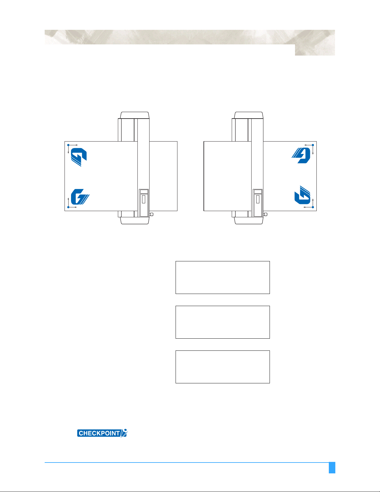
6.7 Rotating the Coordinate Axes
This function is used to move the origin and rotate the coordinate axes by 90° as
shown in the f igure below.
6-13
(Rear Loading)
Y
X
Coordinates when ON
was selected for ROTATE
Coordinates when OFF was
selected for ROTATE
Y
X
(Front Loading)
SETTING OPERATION
1Press the MENU key.
2Press the NEXT key until the follo wing me nu appear s.
INTERFACE>
AREA PARAMETERS>
FUNCTION 1>
FUNCTION 2>
X
Coordinates when OFF
was selected for ROTATE
Coordinates when ON
was selected for ROTATE
Y
Y
X
3Press the F3 key (FUNCTION 1). The following menu appears.
PREF. LINE TYPE>
ROTATE>
MIRROR>
SCALE>
4Press the F2 key (ROTATE). The following menu appears.
ROTATE
ON
OFF*
5 The asterisk “*” in dicate s the curr ently se lected set ting. Pres s the F3 key (ON)
to enable rotation . To di sable rotation , press the F4 key (OFF).
6Press the ENTER key to register your setting .
7Press the MENU key to return the plotter to Rea dy status.
This setting is retai ned in th e plotte r’s intern al memory even whe n the pow er is
turned off.
ADVANCED FUNCTIONS AND OPERATIONS: Rotating the Coordinate Axes
Page 94
6-14
6.8 Setting the Mirror Mode
This function is us ed to cut a rev ersed i mage of the or iginal da ta. In M IRROR
mode, the or igin point and co ordinat e data are rever sed as s hown in t he fig ure
below
<Rear Loading>
<Front Loading>
X
Y
When ON was selected
for MIRROR
When OFF was selected
for MIRROR
Y
X
SETTING PROCEDURE
1Press the MENU key.
2Press the NEXT key until the follo wing me nu appear s.
INTERFACE>
AREA PARAMETERS>
FUNCTION 1>
FUNCTION 2>
3Press the F3 key (FUNCTION 1). The following menu appears.
PREF. LINE TYPE>
ROTATE>
MIRROR>
SCALE>
X
When OFF was selected
for MIRROR
When ON was selected
for MIRROR
X
Y
Y
4Press the F3 key (MIRROR). The following menu appears.
MIRROR
5 The asterisk “*” in dicate s the curr ently se lected set ting. Pres s the F3 key (ON)
to enable the MIRROR mode. To disable the MIRROR mode, press the F4
(OFF) key.
6Press the ENTER key to register your setting .
7Press the MENU key to return the plotter to Rea dy status.
This setting is retai ned in th e plotte r’s intern al memory even whe n the pow er is
turned off.
ADVANCED FUNCTIONS AND OPERATIONS : Setting the Mirror Mode
ON
OFF*
Page 95

6.9 Enlarging or Reducing an Image
This function sets the SCALE factor for enlarging or reducing an image t o be cut or
plotted.
SETTING PROCEDURE
1Press the MENU key.
2Press the NEXT key until the follo wing me nu appear s.
INTERFACE>
AREA PARAMETERS>
FUNCTION 1>
FUNCTION 2>
3Press the F3 key (FUNCTION 1). The following menu appears.
PREF. LINE TYPE>
ROTATE>
MIRROR>
SCALE>
6-15
4Press the F4 key (SCALE). The following menu appears.
SCALE
SCALE FACTOR = 1
5Use the (▲▼) POSITION keys to select the desired scale factor with in the
range of 1/8, 1/4, 1/ 2, 1, 2, 3, 4, 5, 6, 7, and 8.
6Press the ENTER key to register your setting .
7Press the MENU key to return the plotter to Rea dy status.
This setting is retai ned in th e plotte r’s intern al memory even whe n the pow er is
turned off.
ADVANCED FUNCTIONS AND OPERATIONS : Enlarging or Reducing an Image
Page 96

6-16
6.10 Data Sorting Settings
This function so rts the cutting/ plot ting d ata store d in th e buffer mem ory. There are
two data sorting mode s, Area Sorti ng and Pen Sort ing. With Ar ea Sortin g, the
plotter sorts the data to opt imize the movemen t of the media in t he media feed
direction. With Pen S orting, which can be used wit h the 2 -pen mode ls, the plotter
sorts the data so that Pen 1 is use d for plotti ng at the end of th e operation . Area
Sorting is effectiv e for data req uir in g a l arge n umb er of mo vem ents on the draw in g
with the pen raised. Pen Sorting is effect ive for applicat ions where a cutt er pen
and a plotter pen ar e used alternate ly to cut and plot data. Data is sorted so tha t
Pen 1 is used for p lotting at the end of the o peration. When using th e sorting
operations, the start of cutting or plot ting will be de layed by the addi tional time is
required for processing the data in the buffer. Finally, if the data received has been
sorted using the app lication softw are, sorting the data using the plo tter may
require additiona l time. Turning this fun ction off may speed up t he process.
Note: Pen 1 is the pe n mounte d in the pen hold er.
SETTING PROCEDURE
1Press the MENU key.
(2) Press the NEXT key until the followi ng menu ap pears.
INTERFACE>
AREA PARAMETERS>
FUNCTION 1>
FUNCTION 2>
3Press the F4 key (FUNCTION 2). The following menu appears.
DATA SORTING>
AXIS ALIGNMENT>
AUTO PRE FEED>
TANGENT EMULATION>
4Press the F1 key (DATA SORTING). The following menu appears. The menu at
the right appears fo r a 2-pen model .
DATA SORTING
AREA OFF>
5 Press the F3 key to tur n AREA sorting ON or OFF. For the 2-pen model, press
the F4 key to turn PEN so rting O N or O FF.
6Press the ENTER key to register your setting (s).
This setting is retai ned in th e plotte r’s intern al memory even whe n the pow er is
turned off.
CAUTION: If data that has already been sorted by the application or driver software (cut-
ting/plotting order sorted, for example), and then received by the plotter, the
specified order may be changed if this function has been set to ON. In a case
like this, set the function to OFF.
DATA SORTING
AREA OFF>
PEN OFF>
ADVANCED FUNCTIONS AND OPERATIONS : Data Sorting Settings
Page 97

6.11 Auto Registration Mark Reading Function
The plotter uses a se nso r to re ad t he regi st ra ti on ma rk (r efe r enc e lines) pr in ted on
the media, and then ad justs the axes to matc h the coordinate data so that cuttin g
can be performed on pre- prin ted med ia withou t any shift be tween th e prin t and cut
data.
• Regist ration -mark re ading ac curacy * : Wit hin 0.3 m m
* Accuracy when using pens provided with the plotter, high-grade media,
and reading on e of the specif ied patterns.
The registration mark reading sensor is located on the underside of the pen carriage.
6-17
When using Au to Re gistration Mark r ecognit ion, pay at tention to th e follo wing
points:
• The regist ration ma rk patte rn
• The reading ar ea required fo r registra tion mark dete ction
• The registr ation mar k locati ons
• The position of the origin poi nt
• Media on which regi stration mar ks cannot be detect ed
The registration mark patter n
The plotter can re ad (recogniz e) the followi ng registra tion-mark patter ns.
Registration-mark pattern 1
Media feed direction
For instructions on how to change the registration mark pattern, see Section
6.14, “Selecting the Registration MARK TYPE”.
Registration-mark pattern 2
CAUTION:• Application marks used in the application software cannot be used.
• Registration marks must be created as data in the software,
• The following points must be noted when creating registration marks.
- Registration mark line thickness: 0.3 to 1.0 mm
- Registration mark size: 5 to 20 mm (see Section 6.14, “Selecting the Regis-
tration MARK TYPE”).
ADVANCED FUNCTIONS AND OPERATIONS: Auto Registration Mark Reading Function
Page 98

6-18
- Registration marks should be either Pattern 1 or Pattern 2.
- Registration marks should use single lines with the required line thickness
specified.
- The center of the lines is used as the reference point.
The reading area required for registrati on mar k detection
The following ill ustrates the re ading area th e plotter requ ires for dete cting
registrati on ma rks.
Registration mark pattern 1
a
a
Media feed direction
a=6mm
Registration mark reading range
Registration mark pattern 2
a
a
a
a
a=6mm
Registration mark reading range
CAUTION:• If registration marks were created and outp ut u si ng Cu ttin g M ast er Ver. 3.2 or
a later version, the setting de scrib ed in Sec tion 6.13 , “Setting the Reg istrati on
Mark Reading Area”, will be made automatically.
• Incorrect detection may oc c ur i f th ere are marks other than registration marks
within the reading range. If a drawing extends into the registration-mark reading area, see Section 6.13, “Setting the Registration Mark Reading Area”.
• If dirt, dust, or other foreign matter adheres to the media, the plotter may recognize it as a registration mark.
• Be sure to use only black ink for plotting registrati on marks.
The registration mark locations
Blank margins must be left between the edges of the media and the registration
marks to enable the mar ks to be read. Th e following illu strates the location of th e
registration mark s when a cut sheet is used .
Registration mark pattern 1
52
Right pinch
Left pinch roller
Media feed direction
22 15 22 15
ADVANCED FUNCTIONS AND OPERATIONS: Auto Registration Mark Reading Function
roller
25
Registration mark pattern 2
Left pinch roller
52
Right pinch
roller
25
Page 99

6-19
With roll media, the registration marks must be at least 110 mm from the back
edge of the media.
Registration mark pattern 1
Left pinch roller
Media feed direction
22 15 22 15
The position of the origin point
After the registrat ion marks are recog nized, the dr awing origin po int is position ed
as shown belo w.
11020
Right pinch
roller
Registration mark pattern 1
Registration mark pattern 2
Left pinch roller
Registration mark pattern 2
11020
Right pinch
roller
Origin point
Media feed direction
Origin point
CAUTION: The drawing origin point spe cified by the applic ation sof tware mu st be mo ved if
required so that it matches the origin point of the registration marks.
Registration mark pattern 1
Origin point
Media feed direction
Registration mark pattern 2
Origin point
You can measure the offset between the axis origin and the registration mark
using one of two methods.
• Read the numeric values (representing the distance from the axis origin to
the first registration mark) on the screen display of the software application.
• Plot the registration mark and then measure the distance from the origin
point.
ADVANCED FUNCTIONS AND OPERATIONS: Auto Registration Mark Reading Function
Page 100

6-20
Media on which registration marks cannot be detected
The plotter canno t detect regist ration marks on the followi ng types of media.
• Transparent media
→ D ue to the media’s transpar ency, the sensor will detect the surfa ce of the
plotter ’s writing panel, prev enting the accur ate recognit ion of registra tion
marks.
• Any media that is not white or ink that is not black
→ U se of a colored medium or registratio n marks of any color ot her than black
prevents the accu rate rec ognition of r egistrati on marks .
• Coarsely textu red drawings or med ia
→ A medium w ith a stained o r wrink led surfac e or w ith fain tly plo tted r egistra -
tion marks prevents the ac curate recogni tion of registr ation marks.
• Improperly secured media
→ If the m edia th ickness e xceeds 0.3 mm, the registra tion ma rks ca nnct be
detected.
If registration marks cannot be automatically recognized
Use the Axis Alignme nt funct ion. S ee Sectio n 6.23, “AXIS ALIGNME NT Se ttings ”
for details.
ADVANCED FUNCTIONS AND OPERATIONS: Auto Registration Mark Reading Function
 Loading...