

Page 1

CUTTING PLOTTER
SERVICE MANUAL
FC7000-75/100/130/160
FC7000MK2-60/75/100/130/160
FC7000-UM-251-10-9370
Page 2

Page 3

FC7000-UM-251-9370 I
HISTORY OF REVISIONS
No. Date issued Description of revision Page Edition
1 05.06.21 First Printing All 01
2 05.08.29
The cutting mats are added for the recommended parts list.
4-1 02
3 05.08.29
Part number for the right and left media stocker bracket corrected.
10-13 02
4 05.08.31 List of item requiring readjustment corrected. 7-1 02
5 05.11.24 Part number for the bracket bottom corrected. 10-3 03
6 05.11.24 Part number for the media sensor bracket corrected. 10-7 03
7 05.11.24 Part number for the labels added. 10-12 03
8 05.12.13 Part number for the model labels corrected. 10-12 04
9 05.12.13 Part number for the X motor belt corrected. 10-7 04
10 05.12.13 Part number for the pinch roller corrected. 10-10 04
11 06.02.26 The distance adjustment pattern size changed. 7-18 05
12 06.07.04 Part number for the Y drive pulley 38 assy corrected. 10-9 06
13 06.07.04 Part number for the idler pulley assy corrected. 10-9 06
14 06.08.08 Item number for the pinch roller sensor dog corrected. 10-10 07
15 06.10.19 Part number for the idler pulley assy corrected. 10-7 08
16 07.07.11 Information of the FC7000MK added. All 09
17 07.07.13
Information of the new main board for FC7000 added.
4-1,7-1,7-31 09
18 07.10.19
Information of the sensor dog position added.
6-28 10
19 07.10.19 Correction of procedure. 7-14 10
20 07.10.19 Part number for the X motor corrected. 4-1,4-2,10-7,10-9 10
21 07.10.19 Part number for the Y motor corrected. 4-1,4-2,10-7,10-9 10
22 07.10.19 Part number for the Y drive pulley corrected. 10-9 10
Page 4

FC7000-UM-251-9370 II
CONTENTS
1. INTRODUCTION ..................................................................1-1
1.1 Main Specifications ................................................................................................... 1-1
1.1.1 Main Specifications (FC7000 Series) ......................................................................................... 1-1
1.1.2 Main Specifications (FC7000MK2 Series) .................................................................................. 1-1
1.2 External Dimensions .................................................................................................. 1-3
2. PARTS NAMES and FUNCTIONS ..........................................2-1
2.1 Parts Names and Functions ....................................................................................... 2-1
2.2 Assembling the Plotter ..............................................................................................2-3
2.3 Attaching the FC7000 Basket (Option) .......................................................................2-8
2.4 Attaching a Cutter Pen ..............................................................................................2-9
2.5 Replacing the Cross-Cutter Unit ............................................................................... 2-12
3. OPERATIONS .................................................................... 3-1
3.1 Control Panel ............................................................................................................3-1
3.2 Menu List ..................................................................................................................3-3
3.3 Description of Background Settings ...........................................................................3-5
3.4 Setting the Background Settings ................................................................................3-8
4. RECOMMENDED PARTS LIST ............................................. 4-1
5. LIST OF TOOLS ................................................................. 5-1
5.1 Tools ......................................................................................................................... 5-1
5.2 Greasing And Gluing Points ........................................................................................5-1
6. DISASSEMBLY AND REASSEMBLY ..................................... 6-1
6.1 Exterior Parts ............................................................................................................ 6-1
6.1.1 How to Replace the Right Side Cover ........................................................................................6-1
6.1.2 How to Replace the Left Side Cover .......................................................................................... 6-2
6.1.3 How to Replace the Center Cover .............................................................................................6-3
6.1.4 How to Replace the Front Guide ................................................................................................6-4
6.1.5 How to Replace the Rear Guide ................................................................................................. 6-5
6.1.6 How to Replace the Rear Writing Panel .....................................................................................6-6
6.1.7 How to Replace the Front Writing Panel Assembly ..................................................................... 6-7
Page 5

FC7000-UM-251-9370 III
6.2 Mechanical Parts ......................................................................................................6-8
6.2.1 How to Replace the Rear Media Sensor .....................................................................................6-8
6.2.2 How to Replace the Front Media Sensor .................................................................................... 6-9
6.2.3 How to Replace the Pinch Roller ............................................................................................. 6-10
6.2.4 How to Replace the Control Panel Board, LCD Assembly ......................................................... 6-11
6.2.5 How to Replace the Pen Block ................................................................................................ 6-13
6.2.6 How to Replace the Y-belt ....................................................................................................... 6-15
6.2.7 How to Replace the Pinch Roller Sensor .................................................................................. 6-17
6.2.8 How to Replace the Y-relay Board ........................................................................................... 6-19
6.2.9 How to Replace the Cam Sensor .............................................................................................6-20
6.2.10 How to Replace the Y-motor ................................................................................................... 6-21
6.2.11 How to Replace the X-motor ...................................................................................................6-22
6.2.12 How to Replace the Main Board ..............................................................................................6-23
6.2.13 How to Replace the Vacuum Fan ............................................................................................. 6-24
6.2.14 How to Replace the Drive Roller .............................................................................................. 6-25
6.2.15 How to Replace the Cutting Mat .............................................................................................. 6-27
6.2.16 Home Dog Position ................................................................................................................. 6-28
6.2.17 Cross Cutter Dog Position .......................................................................................................6-28
7. ADJUSTMENTS ..................................................................7-1
7.1 List of Items Requiring Readjustment ......................................................................... 7-1
7.2 Mechanical Adjustments ............................................................................................ 7-2
7.2.1 Y-Belt Tension Adjustment ........................................................................................................ 7-2
7.2.2 Y-Drive Belt Tension Adjustment ............................................................................................... 7-3
7.2.3 X-Drive Belt Tension Adjustment ...............................................................................................7-4
7.2.4 Pinch Roller Pressure Adjustment ............................................................................................. 7-5
7.3 Electrical Adjustments ............................................................................................... 7-7
7.3.1 Position of the DIP Switch and Connectors ................................................................................ 7-7
7.3.2 DIP Switch Settings .................................................................................................................. 7-9
7.3.3 Checking the Power Supply Board Voltage Levels .................................................................... 7-10
7.3.4 Explanation of the Values of the Main Board Settings .............................................................. 7-11
7.3.5 Clearing the Non-Volatile RAM ................................................................................................ 7-12
7.3.6 How to Enter the Adjustment Menu ......................................................................................... 7-14
7.3.7 Adjusting the Pen Force .......................................................................................................... 7-16
7.3.8 Adjusting the Distance Accuracy ............................................................................................ 7-18
Page 6

FC7000-UM-251-9370 IV
7.3.9 Adjusting the Auto-Registration Mark Sensor Sensitivity .......................................................... 7-20
7.3.10 Adjusting the Offset of the Auto-Registration Mark Sensor ...................................................... 7-21
7.3.11 Adjusting the Cross Cutter Home Position ............................................................................... 7-23
7.3.12 Adjusting the Offset of the Light Pointer Position ..................................................................... 7-25
7.3.13 Confirming the 2-Pen Model (2-pen model) ............................................................................. 7-26
7.3.14 Adjusting the Pen Exchange Y Direction Value (2-pen model) .................................................. 7-27
7.3.15 Adjusting the Spacing Between Pen 1 and Pen 2
(2-pen model) ............................................................ 7-29
7.3.16 Adjusting the Servo Gain ........................................................................................................ 7-31
7.4 Upgrading the System Firmware .............................................................................. 7-32
8. SERVICE MODES ................................................................8-1
8.1 Sensor Test Mode ...................................................................................................... 8-1
8.2 Control Panel Switch Test Mode .................................................................................8-2
9. TROUBLESHOOTING .......................................................... 9-1
9.1 The Plotter is Turned On But Doesn’t Operate .............................................................9-1
9.2 Media Loading Operations .........................................................................................9-2
9.3 Cutting Operations ....................................................................................................9-3
9.4 Error Messages .........................................................................................................9-4
9.4.1 Hardware Error Messages ........................................................................................................9-4
9.4.2 Error Messages in GP-GL Command Mode ................................................................................9-5
9.4.3 Error Messages in HP-GL Emulation Mode ................................................................................9-6
10. PARTS LIST ......................................................................10-1
10.1 Outer Casing ........................................................................................................... 10-1
10.2 Control Panel .......................................................................................................... 10-3
10.3 Pen Block ................................................................................................................10-5
10.4 Main Frame ............................................................................................................. 10-7
10.5 Y Rail ......................................................................................................................10-9
10.6 Y Slider ................................................................................................................. 10-11
10.7 Wiring Harness ...................................................................................................... 10-12
10.8 Labels ................................................................................................................... 10-13
10.9 Media Stocker,
Stand .................................................................... 10-14
10.10 Option Basket ........................................................................................................ 10-15
Page 7

FC7000-UM-251-9370 V
10.11 Other Parts ........................................................................................................... 10-15
11. BLOCK DIAGRAMS AND CIRCUIT DIAGRAMS ..................... 11-1
11.1 Block Diagrams ....................................................................................................... 11-1
11.1.1 Block Diagrams FC7000 ......................................................................................................... 11-1
11.1.2 Block Diagrams FC7000MK2 .................................................................................................. 11-2
11.2 Circuit Diagrams ..................................................................................................... 11-3
11.2.1 Main Board Top Section .......................................................................................................... 11-3
11.2.2 Main Board (CONNECTOR 1 BLOCK) ....................................................................................... 11-4
11.2.3 Main Board (CONNECTOR BLOCK) .......................................................................................... 11-5
11.2.4 Main Board (CPU BLOCK) ....................................................................................................... 11-6
11.2.5 Main Board (DC DRIVER) ........................................................................................................ 11-7
11.2.6 Main Board (I/F BLOCK) ......................................................................................................... 11-8
11.2.7 Main Board (GRC SERVO BLOCK) ............................................................................................ 11-9
11.2.8 Main Board (MEMORY BLOCK) ...............................................................................................11-10
11.2.9 Main Board (USB BLOCK) .......................................................................................................11-11
11.2.10 Control Board ........................................................................................................................11-12
11.2.11 Relay Board, Pinch Roller Sensor Board, RMS Board ..............................................................11-13
11.3 Circuit Diagrams (FC7000MK2 Main Board) ............................................................11-14
11.3.1 Main Board (CPU) ..................................................................................................................11-14
11.3.2 Main Board (CPU) ..................................................................................................................11-15
11.3.3 Main Board (FPGA) ................................................................................................................11-16
11.3.4 Main Board (I/F) ....................................................................................................................11-17
11.3.5 Main Board (Motor Drive) ......................................................................................................11-18
11.3.6 Main Board (Memory) ............................................................................................................11-19
11.3.7 Main Board (Power Supply) ................................................................................................... 11-20
Page 8

Page 9

FC7000-UM-251-9370 1-1
1. INTRODUCTION
1. INTRODUCTION
1.1 Main Specifications
1.1.1 Main Specifications (FC7000 Series)
FC7000-75 FC7000-100 FC7000-130 FC7000-160
CPU 32-bit
Configuration Grit-rolling plotter
Drive Digital servo
Max. cutting area
(expanded mode)
50m x 762 mm 50m x 1067 mm 50m x 1372 mm 50m x 1626 mm
Guaranteed precision cutting area *110m x 742 mm 10m x 1047 mm 10m x 1352 mm 10m x 1606 mm
Mountable media width Max. 920 mm, Min.
50 mm
Max. 1224 mm, Min.
50 mm
Max. 1529 mm, Min.
50 mm
Max. 1834 mm, Min.
50 mm
Max. cutting speed (Axial) 148.5cm/sec (45 ips)
Specifiable speeds
1, 2, 3, 4, 5, 6, 7, 8, 9, 10, 15, 20, 25, 30, 35, 40, 45, 50, 55, 60, 70, 80, 90, 100, 105 cm/sec
Cutting pressure 48 steps, 0.196-5.88N (20-600gf)
Min. character size 3mm (0.125 in.) alphanumeric Helvetica med. Font
Mechanical resolution 0.005mm
Programmable resolution GP-GL: 0.01/0.05/0.025/0.01mm, HP-GL: 0.025mm
*2
Repeatable accuracy
*1
Max. 0.1 mm/2-m unit (excluding media shrinkage)
Number of cutters/pens 1 (2 for the optional 2-pen models)
*3
Pen types Water-based fiber-tip, oil-based ballpoint, ceramic, and disposable ink pens
Pouncing tool type Pouncing tool: PPA33-TP12, 1.2-mm pin diameter)
*4
Compatible media Mono-vinyl chloride media, fluorescent media, and media for illuminated displays,
high reflective media, up to 0.25mm thick, Sandblast rubber up to 1mm thick
*5
Compatible paper for pouncing Regular paper from 0.06 to 0.13 mm thick
Standard interfaces RS-232C/USB (Auto switching)
Buffer memory 2 MB
Resident command sets GP-GL/HP-GL(Control panel switching)
LCD Panel 20x4 - Supports 7 languages: with amber backlight
Power supply 100-240VAC/50-60 Hz (Auto switching)
Power consumption 140VA max.
Operating environment Temperature: +10˚C to +35˚C
Humidity: 35% to 75% (non-condensing)
Guaranteed accuracy environment Temperature: +16 ˚C to +32 ˚C
Humidity: 35% to 70%(non-condensing)
External dimensions without stand
1260 x 402 x 477mm
1560 x1210 x 715mm
1860 x 1210 x 715mm 2120 x 1210 x 715mm
Weight 29 kg 43 kg
(including stand)
51 kg
(including stand)
59 kg
(including stand)
*1 When the optional basket and Graphtec-specified media are used.
*2 HP-GL is a registered trademark of Hewlett-Packard Company.
*3 The 2-pen unit is a factory-installed option. It cannot be retrofitted.
*4 The PPA32-TP12 pouncing pen cannot be used.
*5 The CB15UA cutter blade and a reinforced backing sheet must be used when cutting high-intensity reflective film.
1.1.2 Main Specifications (FC7000MK2 Series)
Page 10
FC7000-UM-251-9370 1-2
1. INTRODUCTION
FC7000MK2-60 FC7000MK2-75 FC7000MK2-100 FC7000MK2-130 FC7000MK2-160
CPU 32-bit
Configuration Grit-rolling plotter
Drive Digital servo
Max. cutting area
(expanded mode)
50m x 610 mm 50m x 762 mm 50m x 1067 mm50m x 1372 mm50m x 1626
mm
Guaranteed precision cutting area *115m x 590 mm 15m x 742 mm 15m x 1047 mm15m x 1352 mm15m x 1606
mm
Mountable media width Max. 866 mm,
Min. 50 mm
Max. 920 mm,
Min. 50 mm
Max. 1224 mm,
Min. 50 mm
Max. 1529 mm,
Min. 50 mm
Max. 1834 mm,
Min. 50 mm
Max. cutting speed (Axial) 148.5cm/sec (45 ips)
Specifiable speeds
1, 2, 3, 4, 5, 6, 7, 8, 9, 10, 15, 20, 25, 30, 35, 40, 45, 50, 55, 60, 70, 80, 90, 100, 105 cm/sec
Cutting pressure 48 steps, 0.196-5.88N (20-600gf)
Min. character size 3mm (0.125 in.) alphanumeric Helvetica med. Font
Mechanical resolution 0.005mm
Programmable resolution GP-GL: 0.01/0.05/0.025/0.01mm, HP-GL: 0.025mm
*2
Repeatable accuracy
*1
Max. 0.1 mm/2-m unit (excluding media shrinkage)
Number of cutters/pens 1 (2 for the optional 2-pen models)
*3
Pen types Water-based fiber-tip, oil-based ballpoint and disposable ink pens
Pouncing tool type Pouncing tool: PPA33-TP12, 1.2-mm pin diameter)
*4
Compatible media Mono-vinyl chloride media, fluorescent media, and media for illuminated displays,
high reflective media, up to 0.25mm thick, Sandblast rubber up to 1mm thick
*5
Compatible paper for pouncing Regular paper from 0.06 to 0.13 mm thick
Standard interfaces RS-232C/USB (Auto switching)
Buffer memory 2 MB
Resident command sets GP-GL/HP-GL(Control panel switching)
LCD Panel 20x4 - Supports 7 languages: with amber backlight
Power supply 100-240VAC/50-60 Hz (Auto switching)
Power consumption 160VA max.
Operating environment Temperature: +10˚C to +35˚C
Humidity: 35% to 75% (non-condensing)
Guaranteed accuracy environment Temperature: +16 ˚C to +32 ˚C
Humidity: 35% to 70%(non-condensing)
External dimensions without stand
1110 x 402 x
477mm
1260 x 402 x
477mm
1560 x1210 x
715mm
1860 x 1210 x
715mm
2120 x 1210 x
715mm
Weight 22 kg 29 kg 43 kg
(including stand)
51 kg
(including stand)
59 kg
(including stand)
*1 When the optional basket and Graphtec-specified media are used.
*2 HP-GL is a registered trademark of Hewlett-Packard Company.
*3 The 2-pen unit is a factory-installed option. It cannot be retrofitted.
*4 The PPA32-TP12 pouncing pen cannot be used.
*5 The CB15UA cutter blade and a reinforced backing sheet must be used when cutting high-intensity reflective film.
Page 11

FC7000-UM-251-9370 1-3
1. INTRODUCTION
1.2 External Dimensions
FC7000-75, FC7000MK2-60/75
922 (FC7000MK2-60)
1072 (FC7000-75,FC7000MK2-75)
62
170
476.763
383
21
123
94
1110
(FC7000MK2-60)
1260 (FC7000-75,FC7000MK2-75)
Units: mm
Dimensional accuracy: ±5 mm
FC7000-75, FC7000MK2-60/75 with Option Stand
1110 (FC7000MK2-60)
1260 (FC7000-75, FC7000MK2-75)
209 715 90
1190 20
209
715
1014
90
Units: mm
Dimensional accuracy: ±5 mm
Page 12

FC7000-100/130/160
1560 (FC7000-100)
1860 (FC7000-130)
2120 (FC7000-160)
209 715 90
1190 20
209
715
1014
90
Units: mm
Dimensional accuracy: ±5 mm
Page 13

FC7000-UM-251-9370 2-1
2. PARTS NAMES and FUNCTIONS
2. PARTS NAMES and FUNCTIONS
2.1 Parts Names and Functions
Front View
Grit roller
Media sensor
Power switch
Pinch roller
Pen carriage
Cross-cutter unit
Pen holder
Pinch rollers
Control panel
Stand
Cutting groove
Cutting mat
Grit roller position guide
Pen station
Grit roller
Media sensor
Power switch: ................. Used to turn the plotter on and off.
Control panel: ................. Used to access various plotter functions.
Pinch rollers: ................... Rollers that push the media against the grit rollers.
Grit rollers: ...................... Metallic rollers with a file-like surface that feed the media back and forth.
Media sensors: ............... The front sensor is used to sense the leading edge of the media. The rear sensor is
used to sense the trailing edge of the media.
Pen carriage: .................. Moves the cutter-pen or plotting pen across the media during cutting or plotting.
Pen holder: ..................... Holds the cutter-pen or plotting pen and moves it up or down.
Pen station (installed on 2-pen models only):
The second pen is mounted here.
Stand: ............................. Used to make the plotter more portable and to free up counter space.
Grit roller position guide:
Stickers on the front of the Y rail and the rear side of the top cover that show the
position of each grit roller. Use these alignment marks as an aid in locating the
pinch rollers.
Cutting groove: ............... Used when cross-cutting is performed.
Cross-cutter unit: ............ Used to perform cross-cutting of media so that the cut length can be removed from
the roll.
Page 14

FC7000-UM-251-9370 2-2
2. PARTS NAMES and FUNCTIONS
Rear View
Media set lever
AC line inlet
Media stocker
Stock rollers
USB interface connector
Serial interface connector
Media lock
Pinch roller hold-down force switching lever
Media set lever: .............. Used to raise or lower the pinch rollers during the loading or unloading of media.
Pinch roller hold-down force switching lever:
Used to switch between the two pinch roller forces (strong and weak).
AC line inlet: ................... Inlet where the power cord is connected.
Media stocker: ................ Used to carry roll media and ensure its proper rotation.
Stock rollers: ................... A media roll is placed on these rollers.
Media lock: ..................... Used to prevent the stock rollers from rotating when the media roll has been placed
on top of them. The media lock ensures that the media is pulled straight out from
the roll.
USB interface connector:
Used to connect the plotter to the computer with a USB interface cable.
Serial interface connector:
Used to connect the plotter to the computer with an RS-232 serial interface cable.
Page 15
FC7000-UM-251-9370 2-3
2. PARTS NAMES and FUNCTIONS
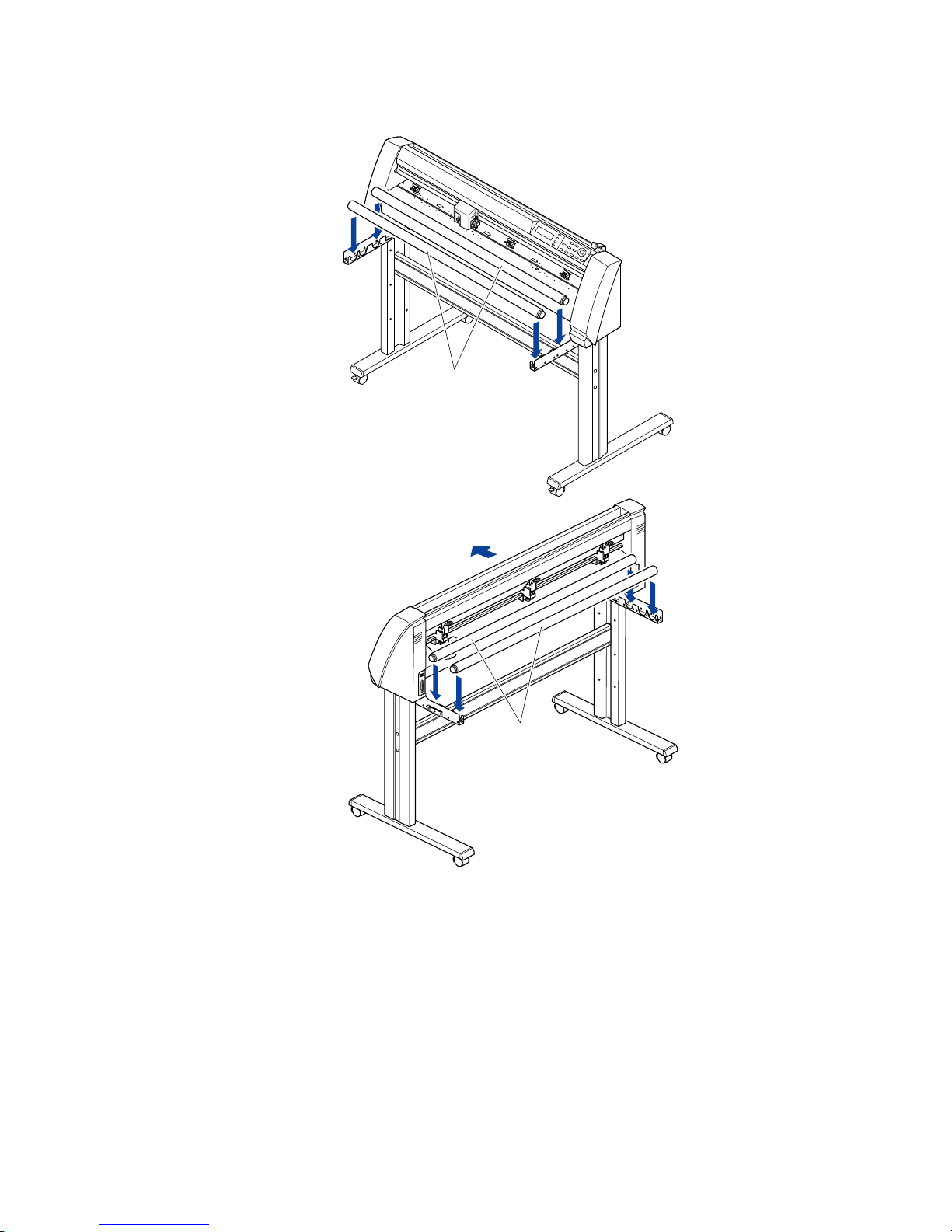
2.2 Assembling the Plotter
FC7000-75 (desktop model; stand not provided but is available as an option)
When the FC7000-75 is used without a stand, the media stocker bracket is attached directly to the plotter.
The media stocker is made up of the following parts.
Stock roller x 2Media stocker bracket x 2 M4 binding-head screw x 4
ATTACHING THE MEDIA STOCKER
(1) Fasten the media stocker brackets to the left and right inside surfaces of the plotter unit, using two M4
binding-head screws for each media stocker bracket.
(2) Insert an M4 screw in the second hole from the front side of the plotter.
• Check that all of the screws used for fastening have been tightened. The media
may not be fed correctly if even one of the screws is loose.
• When installing the plotter, make sure that there are no objects in its vicinity.
Leave a clear space of at least 300 mm around the plotter.
• When the FC7000-75 is used without a stand, the maximum diameter of the roll
media that can be used is 160 mm.
Page 16

FC7000-UM-251-9370 2-4
2. PARTS NAMES and FUNCTIONS
FC7000-100/130/160 (stand provided)
Assemble the stand, attach the media stocker to the stand, and then mount the plotter on the stand.
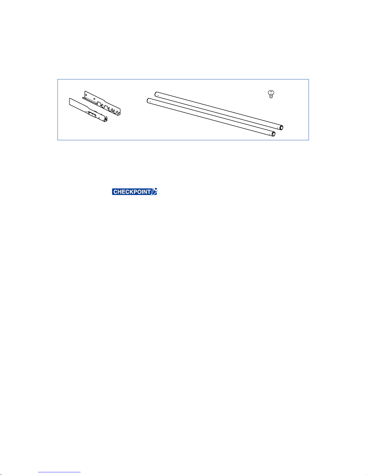
The stand and the media stocker are made up of the following parts.
Base assembly x 2 Allen wrench
(for M5 screws) x 1
Center bar x 1Stand side bar x 2 Socket head cap screw
(M5) x 20
Stock roller x 2
Media stocker bracket x 2
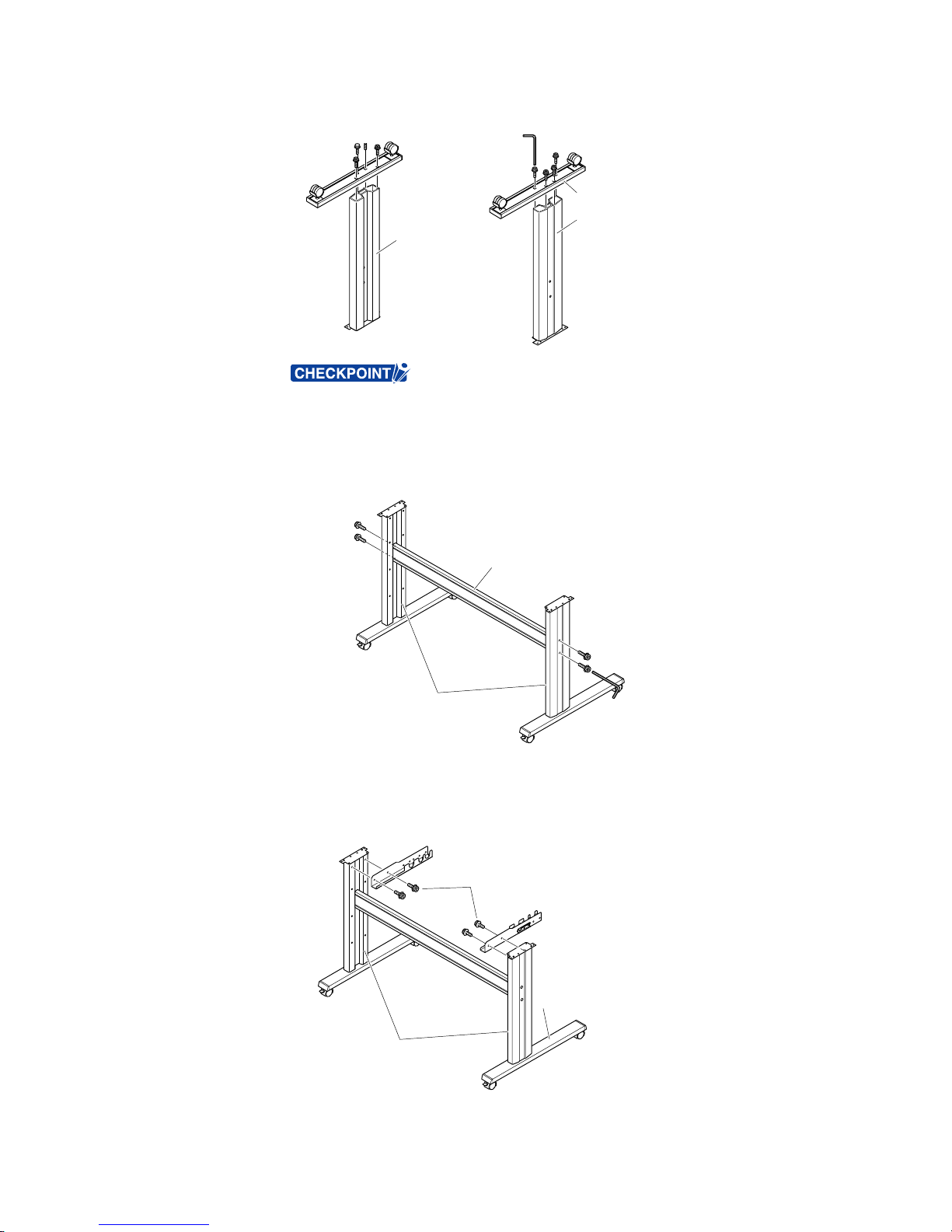
ASSEMBLING THE STAND
The mounting direction is different for the front loading and the rear loading models.
<Front loading>
<Rear loading>
Page 17
FC7000-UM-251-9370 2-5
2. PARTS NAMES and FUNCTIONS
(1) Assemble the left and right stand sides. Fasten a base assembly to each of the stand side bars with four
socket head cap screws, using the Allen wrench.
Socket head
cap screws
Stand side bar
Base assembly
Stand side bar
• Assemble the stand so that the front and rear lengths of the base assembly are
the same for both the left and right stand sides.
(2) Loosely fasten the center bar to the left and right stand sides with four socket head cap screws (two on
each side), using the Allen wrench.
Socket head
cap screws
Socket head
cap screws
Center bar
Stand sides
(3) Attach a media stocker bracket to each of the left and right stand sides with two socket head cap screws,
using the Allen wrench. Mount the media stocker brackets so that each one protrudes directly above the
longer of the two base assembly lengths.
Base assembly
Stand sides
Media stocker bracket
Media stocker bracket
Socket head cap screws
Page 18
FC7000-UM-251-9370 2-6
2. PARTS NAMES and FUNCTIONS
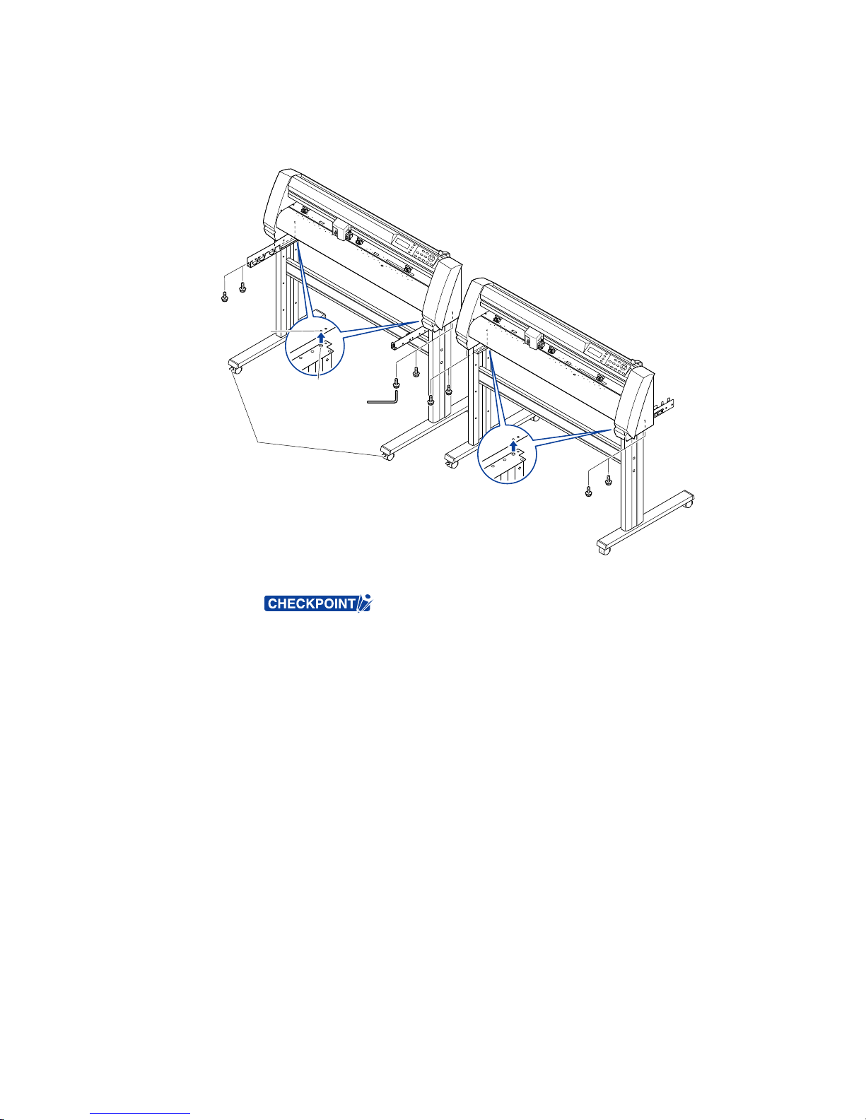
(4) Mount the plotter on the stand by inserting the positioning pins on the stand into the positioning holes
on the underside of the plotter. Fasten with four socket head cap screws (two on each side), using the
Allen wrench.The cutting plotter mounting direction is different for the front loading and the rear loading
models.
Socket head
cap screws
Positioning pin
Socket head
cap screws
Caster stoppers
Positioning pin hole
<Front loading>
<Rear loading>
(5) Tighten the socket head cap screws loosely fastened in Step 2.
• Check that all of the screws used for fastening have been tightened. The media
may not be fed correctly if even one of the screws is loose.
• When installing the plotter, make sure that there are no objects in its vicinity.
Leave a clear space of at least 300 mm around the plotter.
Page 19
FC7000-UM-251-9370 2-7
2. PARTS NAMES and FUNCTIONS
Mounting the stock rollers
Insert the stock rollers into the slots on the media stocker brackets.
Front
Stock rollers
Stock rollers
<Front loading>
<Rear loading>
Page 20
FC7000-UM-251-9370 2-8
2. PARTS NAMES and FUNCTIONS
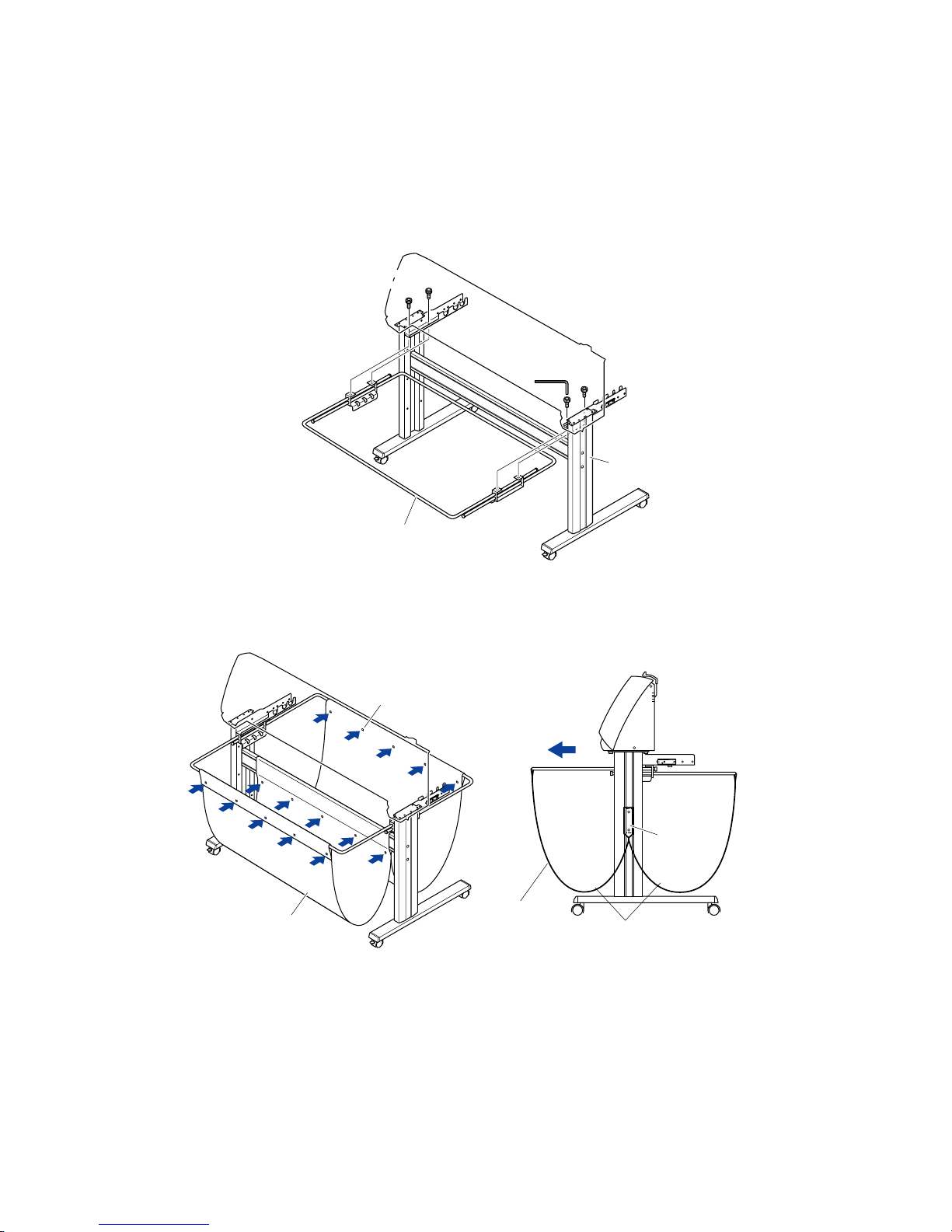
2.3 Attaching the FC7000 Basket (Option)
The FC7000 Basket box contains one basket holder assembly (one front basket tube and one rear basket
tube inserted into two tube brackets), one cloth basket, and a screw/wrench set.
(1) Attach one of the two tube brackets on the basket holder assembly to the left side of the stand with two
socket head cap screws, using the Allen wrench.
Repeat this step with the other side.
Socket head
cap screw
Basket holder assembly
Stand
Socket head
cap screw
(2) Drape the middle section of the cloth basket over the stand’s center bar, and then snap the middle
section of the cloth basket around the center bar. Snap the front edge of the cloth basket around the
front basket tube, and then snap the rear edge of the cloth basket around the rear basket tube.
Cloth basket
Holder snap
Front
Cloth basket
Side view
Separate into front and rear baskets,
with the center bar as the center point
Center bar
Page 21
FC7000-UM-251-9370 2-9
2. PARTS NAMES and FUNCTIONS
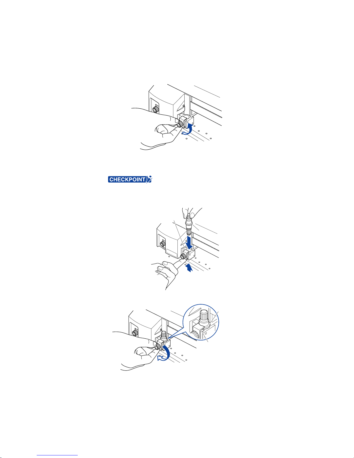
2.4 Attaching a Cutter Pen
When mounting the cutter pen in the pen holder, push the pen all the way into the holder until its flange
contacts the upper part of the holder and then tighten the screw firmly. To prevent injury, avoid touching the
pen immediately after the cutting plotter is turned on or whenever the pen is moving.
(1) Loosen the pen holder screw.
(2) While pushing the pen holder in the upward direction, push the pen all the way into the holder until its
flange contacts the upper part of the holder.
• When pushing the pen holder with your fingers, the blade tip may be protruding.
Take care not to cut your fingers.
Flange
Upper part of pen holder
(3) Make sure that the pen bracket is engaged on the pen’s flange, and then tighten the screw.
Bracket to hold pen
Flange
Page 22

FC7000-UM-251-9370 2-10
2. PARTS NAMES and FUNCTIONS
Attaching a Pen to the Two-Pen Holder (Option)
The two-pen holder is a factory-installed option, and cannot be retrofitted.
(1) Loosen the pen holder screw.
(2) While pushing the pen holder in the upward direction, push the pen all the way into the holder until its
flange contacts the upper part of the holder.
• When you push the pen holder with your fingers, the blade tip may be protruding.
Take care not to cut your fingers.
Flange
Upper part of pen holder
(3) Make sure that the pen bracket is engaged on the pen’s flange, and then tighten the screw.
Bracket to hold pen
Flange
Page 23

FC7000-UM-251-9370 2-11
2. PARTS NAMES and FUNCTIONS
Attaching a Plotting Pen to the Pen Station
(1) Open the pen-hold mechanism on the pen station, and then attach a pen.
(2) Make sure that the bracket of the pen station is engaged in the upper groove of the pen.
(3) Close the pen-hold mechanism on the pen station to hold the pen in place.
• Do not leave a pen attached to the pen station for a long period of time, as the
pen tip will dry up and make it unusable.
• To store the pen, remove it from the pen station and replace its protective cap.
Page 24
FC7000-UM-251-9370 2-12
2. PARTS NAMES and FUNCTIONS
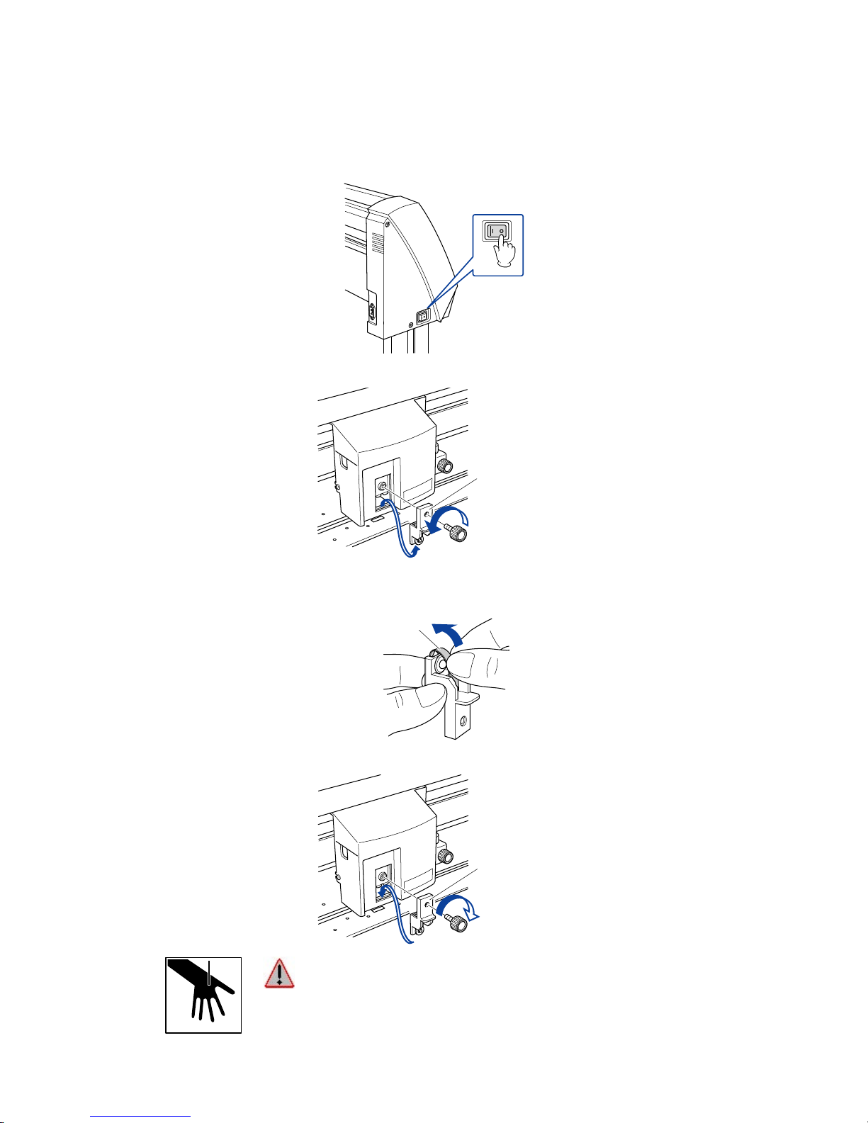
2.5 Replacing the Cross-Cutter Unit
Follow the procedure below to replace the cross-cutter unit that is used to cut the media after the plotting or
cutting operation has been completed.
(1) Check that the power switch is turned off (the “O“ side is pressed down).
(2) Remove the screw holding the cross-cutter unit in place, and then remove the cross-cutter unit.
Cross-cutter unit
(3) Remove the protective cover from the replacement cross-cutter unit. Be sure to remove the protective
cover while holding the part of the unit shown in the figure below.
Protective cover
(4) Attach the replacement cross-cutter unit, and tighten the screw to hold it in place.
Cross-cutter unit
WARNING: The cross-cutter unit uses a very sharp blade. Take care not to cut
yourself on the blade.
Page 25

FC7000-UM-251-9370 3-1
3. OPERATIONS
3. OPERATIONS
3.1 Control Panel
Indicator Lamps
POWER lamp: ................ Remains lit (green) while the plotter is on.
PROMPT lamp: .............. Lights green when the cutting data goes beyond the effective cutting area.
Function Keys
These four keys [F1, F2, F3 and F4] have functions which change as each menu changes. Depending on the
menu being displayed, these keys are used to:
F1 (FORCE) key: ............ When the FC7000 is in MENU mode, press the F1 key to select a function. When
the FC7000 is online, press F1 to select the Condition numbers 1 and 5. After
pressing the CONDITIONS key, use F1 to adjust the cutting/pen FORCE.
F2 (SPEED) key: ............ When the FC7000 is in MENU mode, press the F2 key to select a function. When
the FC7000 is online, press F2 to select the Condition numbers 2 and 6. After
pressing the CONDITIONS key, use F2 to adjust the cutting SPEED.
F3 (QUALITY) key: ......... When the FC7000 is in MENU mode, press the F3 key to select a function. When
the FC7000 is online, press F3 to select the Condition numbers 3 and 7. After
pressing the CONDITIONS key, use F3 to adjust the cutting QUALITY.
F4 (OFFSET) key: .......... When the FC7000 is in MENU mode, press the F4 key to select a function. When
the FC7000 is online, press F4 select the Condition numbers 4 and 8. After
pressing the CONDITIONS key, use F4 to adjust the cutting OFFSET.
Position Keys
POSITION keys .............. Depending on the operating status of the FC7000, the POSITION keys have the
following functions.
When the FC7000 is in MENU mode, use the POSITION keys to change the
setting values shown in the various menu displays. The POSITION keys are also
used to move the pen carriage and the media. If a POSITION key is pressed once,
the pen carriage moves the length of the step specified in Section 5.9, “Using the
MOVE STEP Function of the FC7000 User’s Manual”. If the key is held down, the
movement is continuous. To speed up the movement of the pen carriage, press the
NEXT key together with a POSITION key.
Page 26

FC7000-UM-251-9370 3-2
3. OPERATIONS
Menu Keys
CONDITIONS key: ......... Press CONDITIONS to change the pen conditions shown on the FC7000 display
panel.
HOLD key: ...................... Press HOLD to temporarily suspend cutting or plotting. While the cutting or plotting
operation is suspended, the media set lever can be lowered to enable skewed
media to be reset if necessary.
MENU key: ..................... Press MENU to access the MENU mode. When this key is pressed, the MENU
mode is accessed and the green LED lights. Press it again to cancel MENU mode.
The green LED goes out. Use this key to set the various menu functions. If data is
received after the MENU key has been pressed, that data is temporarily stored in
the plotter’s buffer.
COPY key: ...................... Press COPY to repeat the cutting operation defined by the data in the plotter’s
buffer.
HOME/VIEW key: ........... Press HOME/VIEW to move the pen carriage to the standby position. Press it again
to move the pen carriage to the origin point. Press it one more time to return the
pen carriage to its former position.
NEXT key: ...................... When the FC7000 is in MENU mode, press NEXT to move to the next menu page.
TEST key: ....................... Press TEST to run a cutting test to check whether the currently-selected cutting
conditions are compatible with the media loaded.
AXIS/R.M.S. key: ............ Press AXIS/R.M.S. to initiate automatic reading of the registration marks. If Off
has been selected for the registration mark mode, this key is used to perform axis
alignment.
ORIGIN key: ................... Press ORIGIN to move the origin point. To reset the FC7000, press ORIGIN and
ENTER together when the initial MENU mode screen is displayed.
ENTER key: .................... Press ENTER to register your setting after setting a function.
To reset the FC7000, press ENTER and ORIGIN together when the INITIAL MENU
mode screen is displayed. The cutting area can also be displayed by pressing the
ENTER key in Ready status.
Page 27
FC7000-UM-251-9370 3-3
3. OPERATIONS
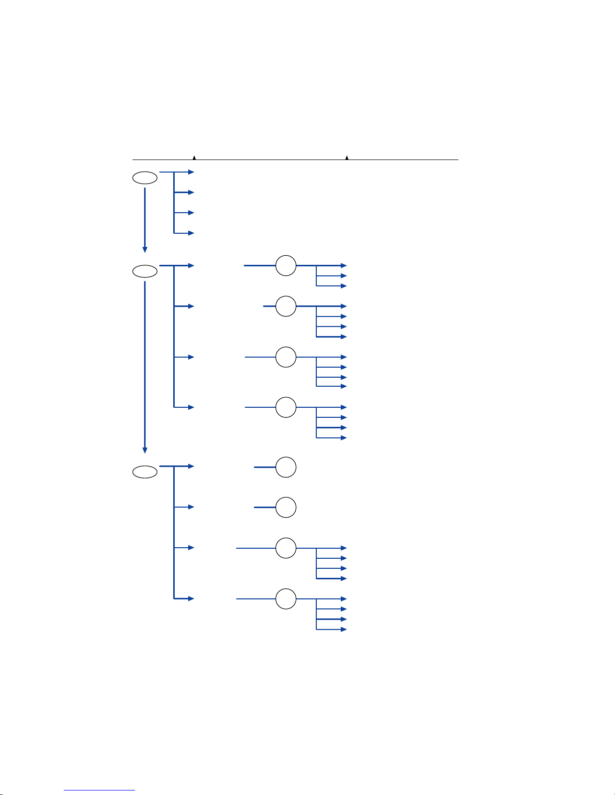
3.2 Menu List
When the FC7000 is in MENU mode
The Main menu can be accessed by pressing the NEXT key when the plotter is in MENU mode (the MENU
lamp is lit). Press the corresponding function key to select the sub menu when the desired main menu
appears.
Page Main menu Sub menu
ASSIGN PEN (2-pen model only)
INTER
FACE
AREA PARAMETERS
FUNCTION 1
FUNCTION 2
CROSS CUT
PRE FEED
MOVE STEP
STE
P SIZE (GP-GL only)
ORIGIN (HP-G
L only)
ROTATE
PER
F. LINE TYPE
DATA SORTING
RS-232C
COMMAND
AREA
PAGE LENGTH
EX
PAND
SCALE
MIRROR
AXIS
ALIGNMENT
AU
TO FEED
TANGENT EMULATION
NEXT
NEXT
F1
FORCE
F2
SPEED
F3
QUALITY
F4
OFFSET
BACKGROUND
SETTINGS
OPTION 1
OPTION 2
PEN U
P SPEED
OFFSE
T ANGLE
OFFSE
T FORCE
STE
P PASS
NEXT
PEN OFFSET ADJ. (2-pen model only)
INITIA
L DOWN FORCE
DIS
TANCE ADJUST
TEST
F3
QUALITY
F2
SPEED
PEN UP/DOWN
F1
FORCE
F4
OFFSET
Page 28

FC7000-UM-251-9370 3-4
3. OPERATIONS
When the power is turned on without any media loaded
If the power is turned on without any media loaded in the plotter, the initial menu is displayed on the LCD.
The initial menu configuration is as follows.
Main menu Sub menu
Initial menu
STEP SIZE (GP-GL only)
AUTO REG. MARK
RS-232C
COMMAND
AUTO PRE FEED
INITIAL FEED SPEED
INTERFACE
F4
OFFSET
F4
OFFSET
Page 29

FC7000-UM-251-9370 3-5
3. OPERATIONS
3.3 Description of Background Settings
The FC7000 is provided with the special functions listed below.
• Display Language Setting (LANGUAGE SELECTION)
This function sets the language used on the display. One of seven languages can be selected: English,
French, German, Italian, Portuguese, Spanish, or Japanese.
• Enabling/Disabling the “;” and “:” Commands (COMMAND ; and :)
Note: This function can only be specified when the COMMAND setting is GP-GL.
This function enables or disables the “;” and “:” commands when the COMMAND setting is GP-GL. If
the first part of the data is lost, these commands may be having an adverse effect. In this case, set this
function to DISABLED (the default setting is ENABLED).
• Moving the Pen While Raised or Lowered in Response to the “W” Command (“W” COMMAND)
Note: This function can only be specified when the COMMAND setting is GP-GL.
This function selects whether, upon receipt of the “W” command for the drawing of arcs, the plotter
moves the pen to the specified starting position in the raised status or in the pen status (raised or
lowered) that was in effect immediately prior to receipt of the “W” command.
When PEN DOWN is selected, the pen is moved to the starting position for the drawing of arcs in the
pen status (raised or lowered) that was in effect immediately prior to receipt of the “W” command. When
PEN UP is selected, the pen is moved to the starting position for the drawing of arcs in the raised status.
This setting is only effective if a cutter blade has been selected in the cutter-pen settings.
• Model ID Response (MODEL EMULATED)
Note: This function can only be specified when the COMMAND setting is HP-GL™.
This function sets the response to the “OI” command when the COMMAND setting is HP-GL™.
When 7550 is set, the “OI” command response is 7550.
When 7586 is set, the “OI” command response is 7586.
• Setting Priority (CONDITION PRIORITY)
This function sets whether the plotter places priority on the cutting conditions specified through command
input from the computer or through manual settings (on the plotter control panel).
When MANUAL is selected, cutting is performed using the cutting conditions set at the control panel,
and cutting conditions sent from the computer are ignored.
When PROGRAM is selected, the cutting conditions can be set either at the plotter’s control panel or by
command input from the computer. The most recent setting conditions are set. When the power is turned
off, only the conditions set at the control panel are retained in the plotter’s internal memory.
• Enabling/Disabling the Pen Select Command (PEN SELECT)
Note: This function can only be specified for a 2-pen model.
This function enables or disables the PEN SELECT command (“J” Command in GP-GL mode or the “SP”
command in HP-GL™ mode) for a 2-pen model.
Page 30

FC7000-UM-251-9370 3-6
3. OPERATIONS
• Initial Blade Tip Position Setting (INITIAL BLADE CONTROL POSITION)
The cutter blade is placed on the medium to orient it after the power is turned on or the cutter-pen
conditions are set. This is referred to as “initializing” the cutter blade.
This function sets the “Initial Blade Tip Position” for this operation.
When 2 mm BELOW is selected, initial blade control is performed at a position 2 mm below the cutting
start position.
When OUTSIDE is selected, initial blade control is performed outside of the effective cutting/plotting
area.
• Setting the Display Length Unit (LENGTH UNIT)
This function enables you to set the unit for coordinates appearing on the display panel to either
millimeter or inch units.
• Enabling/Disabling Pen Up Move (PEN UP MOVE)
This function sets whether the pen will travel to each point specified or only from the initially specified
point to the last specified point when consecutive commands are received specifying pen movement
while it is raised.
When ENABLED is selected, the pen travels consecutively to each coordinate specified by the data
received.
When DISABLED is selected, the pen travels directly from the initially specified point to the last specified
point.
• Enabling/Disabling the Media Sensors (MEDIA SENSOR)
This function enables or disables the media sensors that detect the size of the medium in the feed
direction.
When ENABLED is selected, the feed-direction media sensors are enabled.
When DISABLED is selected, the feed-direction media sensors are disabled.
• Enabling/Disabling the Pinch Roller Sensors (PINCH ROLLER SENSOR)
This function enables or disables the pinch roller sensors that detect the width of the medium.
When ENABLED is selected, the pinch roller sensors are enabled.
When DISABLED is selected, the pinch roller sensors are disabled.
• Since the pinch roller sensors are also used for the cross-cutting operation, cross-
cutting cannot be performed if DISABLED is selected.
• Circle-Command Resolution Setting (CIRCLE RESOLUTION)
Note: This function can only be specified when the COMMAND setting is HP-GL™.
This function sets whether the resolution is automatically set or fixed at a constant 5 degrees when a
plotter circle command is output while the COMMAND setting is HP-GL™.
• Cross-cut Force Setting (CROSS CUT PRESSURE)
This function sets the cutting force for the cross-cut operation.
The default value is 30, but the setting should be changed to suit the media type.
Thin media: Decrease the value.
Thick media: Increase the value.
Page 31

FC7000-UM-251-9370 3-7
3. OPERATIONS
• Enabling or Disabling the 1/2 Pen Setting (CHECK PEN)
Note: This function can only be specified for a 2-pen model.
This function checks whether the physical PEN 2 is actually mounted in the pen station during the media
detection operation on a 2-pen model.
When ENABLED is selected, a check is performed
When DISABLED is selected, a check is not performed. If DISABLED is selected, always check that
PEN 2 is mounted in the pen station before turning on the power.
• Fan Suction Setting (FAN POWER)
This function sets the suction force used to affix media to the plotter.
Thin media: Weak
Normal media: Normal
• Enabling/Disabling the Beep Setting (BEEP FOR KEY OPERATION)
This function selects whether to enable or disable the beep that is emitted whenever a control panel key
is pressed.
ON: The beep sounds.
OFF: The beep does not sound.
• Enabling/Disabling Auto Registration Mark Recognition (MARK AUTO SCAN)
This function enables or disables the automatic sensing of registration marks from the plug-in software.
ON: The registration marks are sensed automatically.
OFF: The registration marks are not sensed automatically.
CAUTION: If DISABLED was selected for the media or pinch roller sensors, be sure
to specify the cutting or plotting area. If the cutting or plotting area is not
specified, the blade tip and the cutting mat may be damaged, and the pen
carriage may strike the sides of the plotter.
Page 32
FC7000-UM-251-9370 3-8
3. OPERATIONS
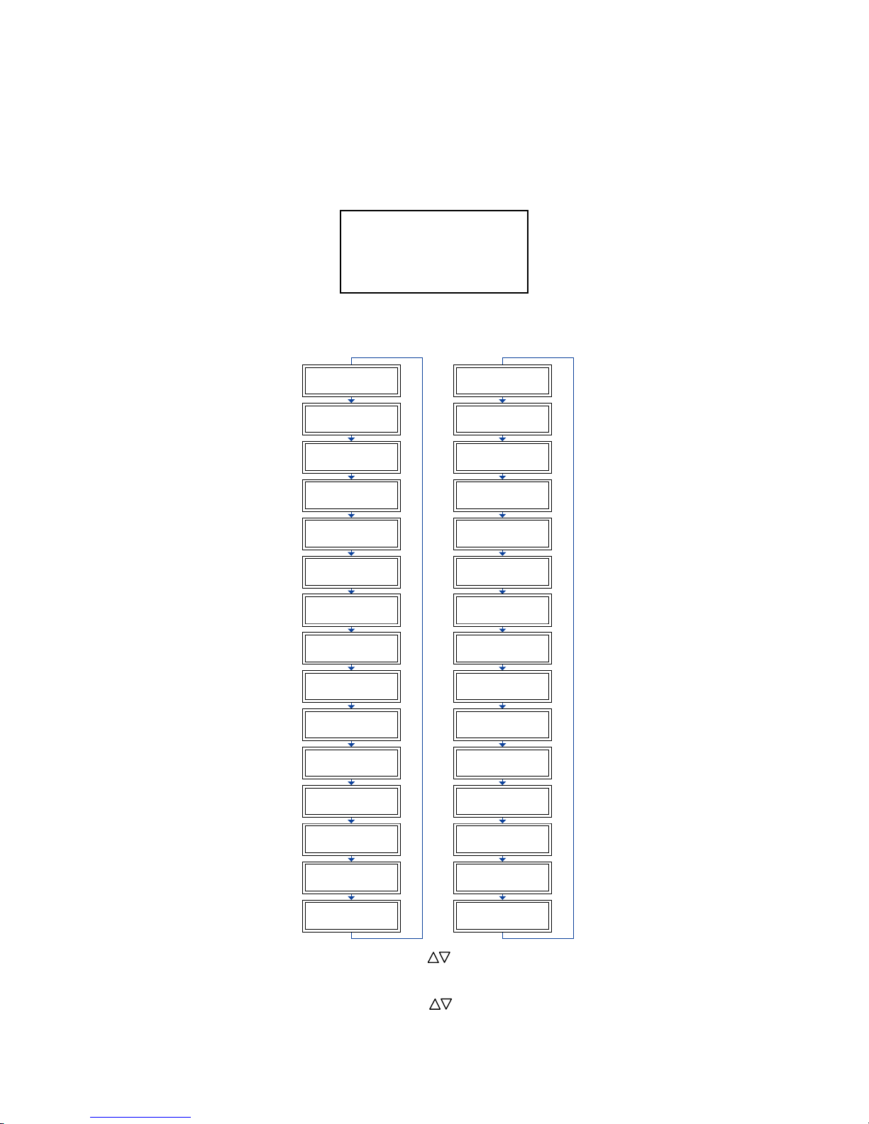
3.4 Setting the Background Settings
SETTING PROCEDURE
(1) Use the following procedure to display the background setting menus.
Load media in the plotter, and then turn on the power. Press the MENU key and then press the NEXT
key until the following menu appears.
PEN UP/DOWN>
BACKGROUND SETTINGS>
OPTION 1>
OPTION 2>
Press the F2 key (BACKGROUND SETTINGS) to enter the setting mode.
(2) Press the NEXT key to move through the BACKGROUND SETTINGS menus in the displayed sequence.
GP-GL
Background Settings
*2-Pen Model
*2-Pen Model
*2-Pen Model
*2-Pen Model
LANGUAGE SELECTION
[ JA
PANESE ]
COMMAND ;
AND :
ENABLE
D *
DISABLED
"W" COMMAND
PEN U
P
PEN DOW
N*
CONDITION PRIORITY
MANUA
L*
PROGRAM
INITIA
L BLADE
CONTRO
L POSITION
2mm BELOW *
OUTSIDE
LENGTH UNI
T
INCH
METRIC*
PEN U
P MOVE
ENABLE
D *
DISABLED
MEDIA SENSOR
ENABLED
*
DISABLED
PINCH ROLLER SENSOR
ENABLED
*
DISABLED
CROSS CUT PRESSURE
30
CHECK PEN
ENABLED
*
DISABLED
FAN POWER
WEAK
NORMAL*
BEEP
FOR KEY OPERATION
OFF
ON*
MARK AUTO SCAN
ON
OF F *
LANGUAGE SELECTION
[ JA
PANESE ]
MODEL EMULATED
7550*
7586
CONDITION PRIORITY
MANUAL*
PROGRAM
PEN SELECT
ENABLE
D*
DISABLED
PEN SELECT
ENABLED
DISABLED
INITIA
L BLADE
CONTRO
L POSITION
2mm BELOW*
OUTSIDE
LENGTH UNI
T
INCH
METRIC
*
PEN U
P MOVE
ENABLED
DISABLED
*
MEDI
A SENSOR
ENABLE
D*
DISABLED
PINCH ROLLER SENSOR
ENABLE
D*
DISABLED
CIRCLE RESOLUTION
AU
TO
DE
FAULT*
CROSS CUT PRESSURE
30
CHECK PEN
ENABLED
*
DISABLED
FAN POWER
WEAK
NORMAL*
BEEP
FOR KEY OPERATION
OFF
ON*
MARK AUTO SCAN
ON
OF F*
HP-GL
TM
Background Settings
(3) At the LANGUAGE SELECTION menu, use the ( ) POSITION keys to select the desired language
and then press the ENTER key.
At the CROSS CUT PRESSURE menu, use the ( ) POSITION keys to increase or decrease the value
and then press the ENTER key.
Page 33

FC7000-UM-251-9370 3-9
3. OPERATIONS
For all other displays, press the F3 or the F4 key to move the asterisk to your desired choice, and then
press the ENTER key. The asterisk indicates the currently selected setting. If you do not wish to change
the currently displayed setting, press the NEXT key to move to the next menu.
(4) Turn off the power when all the settings are completed.
• These settings are retained in the plotter’s memory even when the power is
turned off.
Page 34

Page 35
FC7000-UM-251-9370 4-1
4. RECOMMENDED PARTS LIST
4. RECOMMENDED PARTS LIST
FC7000-75/100/130/160
No. Par t No. Description -75 -100 -130 -160 Remarks
1 772126500 Main Board for FC7000 1 1 1 1 FC7000
792700703 New Main Board for the FC7000 1 1 1 1 Same as FC7000Mk2
2 50 0052449 Switching Power Supply Unit 1 1 1 1 PS3122
3 500052478 LG-217D-3, Cam Sensor 1 1 1 1
4 500052515 PS-117ED1 2 2 2 2 Paper Sensor
5 682132430 UGJMEE-A7JGR34 – 1 1 1 X motor
6 682132440 UGJMEE-A7MGR73 2 1 1 1 Y motor, XY motor for 75
7 772126660 Pen Board 1 1 1 1
8 772126650 Pinch Roller Sensor Board 1 1 1 1
9 692126531 FFC312203A , Flexible Cable 75 1 – – –
10 692126541 FFC312204A, Flexible Cable 100 – 1 – –
11 692126551 FFC312205A, Flexible Cable 130 – – 1 –
12 692126561 FFC312206A, Flexible Cable 160 – – – 1
13 772126700 Pen Block Assembly 1 1 1 1
14 772126710 Light Pointer Assembly 1 1 1 1
15 772126720 Registration Mark Sensor Board, PR312207A 1 1 1 1
16 50 0052472 TDS- 05B-DC12V, Fan 1 2 2 2
17 772126560 LCD Assembly 1 1 1 1
18 772126570 Control Panel Board, PR312208A 1 1 1 1
19 692126521 FFC312202A, Control Panel Flexible Cable 1 1 1 1
20 772126340 Cross Cutter Assembly 1 1 1 1
21 621261220 150S2M-1150, Y Belt 75 1 – – –
22 621262020 Drive Roller Set 75 1 – – –
23 621262010 Drive Roller Shaft 75 1 – – –
24 621271220 300S2M-1450, Y Belt 100 – 1 – –
25 621272020 Drive Roller Set 100 – 1 – –
26 621272010 Drive Roller Shaft 100 – 1 – –
27 621281220 300S2M-1750 – – 1 –
28 621282020 Drive Roller Set 130 – – 1 –
29 621282010 Drive Roller Shaft 130 – – 1 –
30 621291220 300S2M-2010 – – – 1
31 621292020 Drive Roller Set 160 – – – 1
32 621292011 Drive Roller Shaft 160 – – – 1
33 095002121 Push Roller 2 3 3 3
34 378413041 130TN15-10W, Motor Belt 2 2 2 2
35 095013010 Roller BB13, Y Slider Roller 7 7 7 7
36 621261053 Cutting Mat 75 1 – – –
37 621271053 Cutting Mat 100 – 1 – –
38 621281053 Cutting Mat 130 – – 1 –
39 621291053 Cutting Mat 160 – – – 1
Page 36

FC7000-UM-251-9370 4-2
4. RECOMMENDED PARTS LIST
FC7000MK2
No. Par t No. Description -60 -75 -100 -130 -160 Remarks
1 792700703 Main Board for FC7000Mk2 1 1 1 1 1 FC7000MK2
2 50 0052449 Switching Power Supply Unit 1 1 1 1 1 PS3122
3 500052478 LG-217D-3, Cam Sensor 1 1 1 1 1
4 500052515 PS-117ED1 2 2 2 2 2 Paper Sensor
5 682126200 DMN37HE-0 03 1 1 – – – X motor
682132430 UGJMEE-A7JGR34 – – 1 1 1
6 682126200 DMN37HE-0 03 1 1 1 1 1 Y motor
7 772126660 Pen Board 1 1 1 1 1
8 772126650 Pinch Roller Sensor Board 1 1 1 1 1
9 692126531 FFC312203A , Flexible Cable 60/75 1 1 – – –
692126541 FFC312204A, Flexible Cable 100 – – 1 – –
692126551 FFC312205A, Flexible Cable 130 – – – 1 –
692126561 FFC312206A, Flexible Cable 160 – – – – 1
10 772126700 Pen Block Assembly 1 1 1 1 1
11 772126710 Light Pointer Assembly 1 1 1 1 1
12 772126720 Registration Mark Sensor Board, PR312207A 1 1 1 1 1
13 500052472 TDS- 05B-DC12V, Fan 1 1 2 2 2
14 772126560 LCD Assembly 1 1 1 1 1
15 772126570 Control Panel Board, PR312208A 1 1 1 1 1
16 692126521 FFC312202A, Control Panel Flexible Cable 1 1 1 1 1
17 772126340 Cross Cutter Assembly 1 1 1 1 1
18 621391220 150S2M1000, Y Belt 60 1 – – – –
621261220 150S2M-1150, Y Belt 75 – 1 – – –
621271220 300S2M-1450, Y Belt 100 – – 1 – –
621281220 300S2M-1750, Y Belt 130 – – – 1 –
621291220 300S2M-2010, Y Belt 160 – – – – 1
19 621392020 Drive Roller set 60 1 – – – –
621262020 Drive Roller Set 75 – 1 – – –
621272020 Drive Roller Set 100 – – 1 – –
621282020 Drive Roller Set 130 – – – 1 –
621292020 Drive Roller Set 160 – – – – 1
20 621391340 Drive Roller Shaft 60 1 – – – –
621262010 Drive Roller Shaft 75 – 1 – – –
621272010 Drive Roller Shaft 100 – – 1 – –
621282010 Drive Roller Shaft 130 – – – 1 –
621292011 Drive Roller Shaf t 160 – – – – 1
21 095002121 Push Roller 2 2 3 3 3
22 378413041 130TN15-10W, Motor Belt 2 2 2 2 2
23 095013010 Roller BB13, Y Slider Roller 7 7 7 7 7
24 621390050 Cutting Mat 60 1 – – – –
621261053 Cutting Mat 75 – 1 – – –
621271053 Cutting Mat 100 – – 1 – –
621281053 Cutting Mat 130 – – – 1 –
621291053 Cutting Mat 160 – – – – 1
Page 37

FC7000-UM-251-9370 5-1
5. LIST OF TOOLS
5. LIST OF TOOLS
5.1 Tools
No. Adjustment Item Jig Tool
1 Pen force adjustment Cutter Pen Holder (CB09) Colex gauge (50,300,500 gf)
2 Distance adjustment Glass scale
3 Pen block height adjustment 10 mm height block
4 Firmware update PC, USB I/F cable
5 X-drive belt tension adjustment Push-pull gauge (2 kg)
6 Y-drive belt tension adjustment Push-pull gauge (2 kg)
7 Replacing the main board
Screwdriver
8 Replacing the vacuum fan
5.2 Greasing And Gluing Points
No. Grease or Glue Point Grease or Glue name Application quantity
1 Cam Shinetu silicon grease G501 Suitable quantity
2 X-drive motor pulley Shinetu silicon grease G501 Suitable quantity
3 Y-drive motor pulley Shinetu silicon grease G501 Suitable quantity
4 X-drive pulley Shinetu silicon grease G501 Suitable quantity
5 Y-drive pulley Shinetu silicon grease G501 Suitable quantity
6 Y-tension pulley Shinetu silicon grease G501 Suitable quantity
7 Y-rail, pinch roller assy sliding area Shinetu silicon grease G501 Suitable quantity
8 Y-motor drive pulley set screws Loctite 222 Small quantity
9 X-motor drive pulley set screws Loctite 222 Small quantity
10 X-drive pulley set screws Loctite 222 Small quantity
Page 38

Page 39
FC7000-UM-251-9370 6-1
6. DISASSEMBLY AND REASSEMBLY
6. DISASSEMBLY AND REASSEMBLY
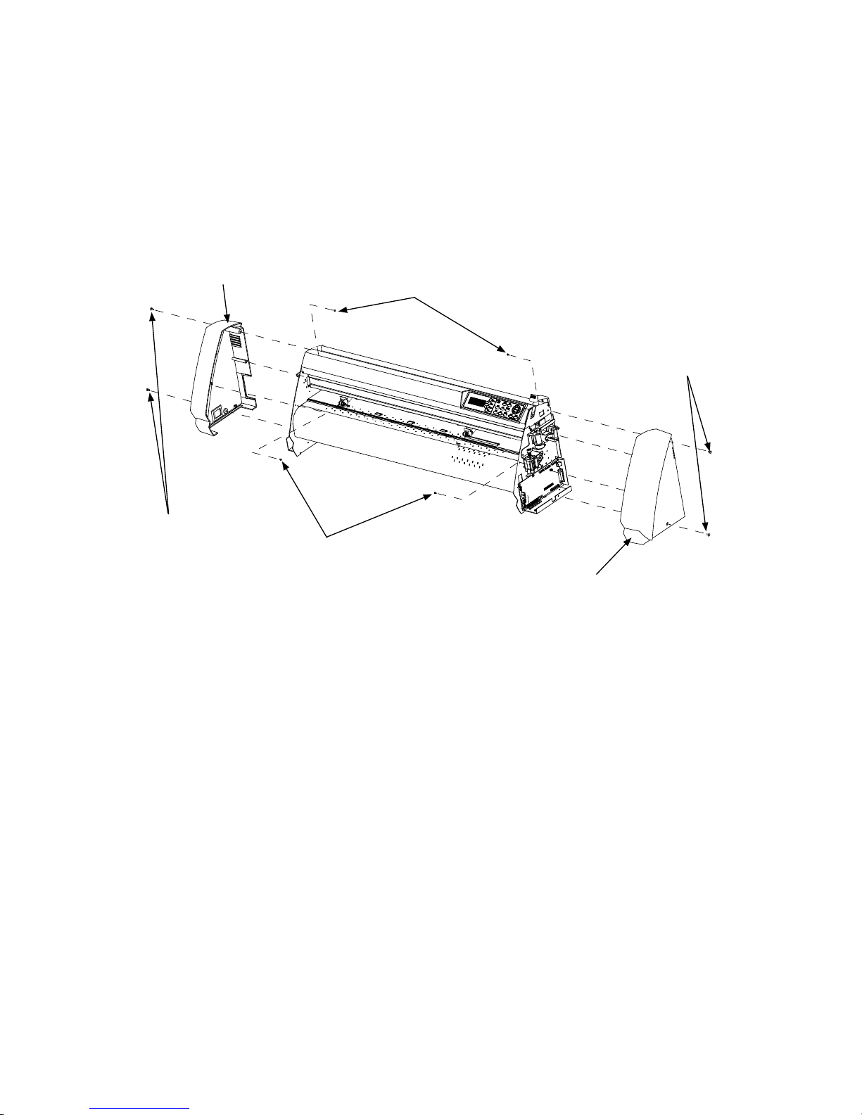
6.1 Exterior Parts
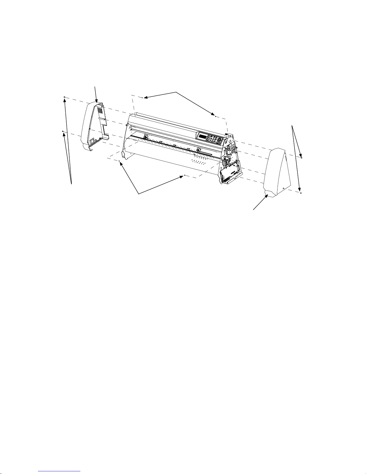
6.1.1 How to Replace the Right Side Cover
How to detach the right side cover
(1) Remove the two M4L6 binding head screws from the right side cover.
(2) Remove the two M3L6 binding head screws from the right side plate.
M4L6 binding head screw
M4L6 binding head screw
M3L6 binding head screw
M3L6 binding head screw
Right side cover
Left side cover
How to reinstall the right side cover
(1) Mount the right side cover to the right side plate.
(2) Fasten the two M4L6 binding head screws and the two M3L6 binding head screws.
Page 40
FC7000-UM-251-9370 6-2
6. DISASSEMBLY AND REASSEMBLY
6.1.2 How to Replace the Left Side Cover
How to detach the left side cover
(1) Remove the two M4L6 binding head screws from the left side cover.
(2) Remove the two M3L6 binding head screws from the left side plate.
M4L6 binding head screw
M4L6 binding head screw
M3L6 binding head screw
M3L6 binding head screw
Right side cover
Left side cover
How to reinstall the left side cover
(1) Mount the left side cover to the left side plate.
(2) Fasten the two M4L6 binding head screws and the two M3L6 binding head screws.
Page 41
FC7000-UM-251-9370 6-3
6. DISASSEMBLY AND REASSEMBLY
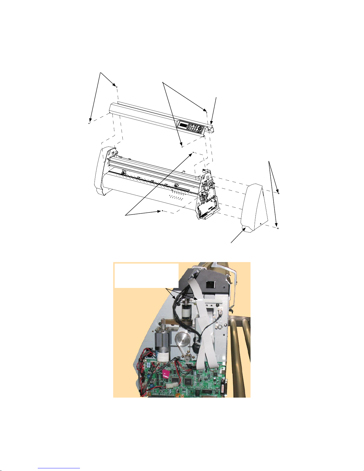
6.1.3 How to Replace the Center Cover
How to detach the center cover
(1) Detach the right side cover (see Subsection 6.1.1).
M4L6 binding head screw
M3L6 binding head screw
M3L6 binding head screw
Right side cover
Center cover assembly
M3L6 binding head screw
(2) Disconnect the cables from connector J2 and J3 on the main board.
Disconnect the cables
from connector J2 and
J3 on the main board.
(3) Remove the four M3L6 binding head screws from the center cover assembly.
(4) Detach the center cover assembly.
How to reinstall the center cover assembly
(1) Reattach the center cover assembly in the reverse order in which it was detached.
Page 42

FC7000-UM-251-9370 6-4
6. DISASSEMBLY AND REASSEMBLY
6.1.4 How to Replace the Front Guide
How to detach the front guide
(1) Remove the four M3L6 binding head screws from the front guide for the FC7000-75.
(Remove the five M3L6 binding head screws from the front guide for the FC7000-100.
Remove the six M3L6 binding head screws from the front guide for the FC7000-130.
Remove the seven M3L6 binding head screws from the front guide for the FC7000-160.)
(2) Detach the front guide.
Front guide
M3L6 binding head screw
How to reinstall the front guide
(1) Reattach the front guide in the reverse order in which it was detached.
Page 43

FC7000-UM-251-9370 6-5
6. DISASSEMBLY AND REASSEMBLY
6.1.5 How to Replace the Rear Guide
How to detach the rear guide
(1) Remove the four M3L6 binding head screws from the rear guide for the FC7000-75.
(Remove the five M3L6 binding head screws from the rear guide for the FC7000-100.
Remove the six M3L6 binding head screws from the rear guide for the FC7000-130.
Remove the seven M3L6 binding head screws from the rear guide for the FC7000-160.)
(2) Detach the rear guide.
Rear guide
M3L6 binding head screw
How to reinstall the rear guide
(1) Reattach the rear guide in the reverse order in which it was detached.
Page 44

FC7000-UM-251-9370 6-6
6. DISASSEMBLY AND REASSEMBLY
6.1.6 How to Replace the Rear Writing Panel
How to detach the rear writing panel
(1) Detach the rear guide (see Subsection 6.1.5).
(2) Remove the M3L6 binding head screw from the top of the rear writing panel.
(3) Remove the five M3L6 binding head screws from the rear of the rear writing panel for the FC7000-75.
(Remove the five M3L6 binding head screws from the rear of the rear writing panel for the FC7000-100.
Remove the six M3L6 binding head screws from the rear of the rear writing panel for the FC7000-130.
Remove the seven M3L6 binding head screws from the rear of the rear writing panel for the
FC7000-160.)
(4) Detach the rear writing panel.
Rear writing panel
M3L6 binding head screw
M3L6 binding head screw
How to reinstall the rear writing panel
(1) Reattach the rear writing panel in the reverse order in which it was detached.
Page 45

FC7000-UM-251-9370 6-7
6. DISASSEMBLY AND REASSEMBLY
6.1.7 How to Replace the Front Writing Panel Assembly
How to detach the front writing panel assembly
(1) Detach the front guide (see Subsection 6.1.4).
(2) Detach the rear writing panel (see Subsection 6.1.6).
(3) Remove the five M3L6 binding head screws from the front writing panel assembly for the FC7000-75.
(Remove the six M3L6 binding head screws from the front writing panel assembly for the FC7000-100.
Remove the seven M3L6 binding head screws from the front writing panel assembly for the FC7000-130.
Remove the eight M3L6 binding head screws from the front writing panel assembly for the FC7000-160.)
(4) Loosen the five M3L6 binding head screws at the top of the front writing panel assembly for the
FC7000-75.
(Loosen the six M3L6 binding head screws at the top of the front writing panel assembly for the
FC7000-100.
Loosen the seven M3L6 binding head screws at the top of the front writing panel assembly for the
FC7000-130.
Loosen the eight M3L6 binding head screws at the top of the front writing panel assembly for the
FC7000-160.
(5) Detach the front writing panel assembly.
Front writing panel
M3L6 binding head screw
Loosen these M3L6 binding head screws
How to reinstall the front writing panel assembly
(1) Reattach the front writing panel in the reverse order in which it was detached.
Page 46

FC7000-UM-251-9370 6-8
6. DISASSEMBLY AND REASSEMBLY
6.2 Mechanical Parts
6.2.1 How to Replace the Rear Media Sensor
How to detach the rear media sensor
(1) Detach the rear guide (see Subsection 6.1.5).
(2) Remove the M3L10 binding head screw attaching the rear media sensor.
(3) Disconnect the sensor from the connector.
Rear media sensor
M3L10 binding head screw
How to reinstall the rear media sensor
(1) Reattach the rear media sensor in the reverse order in which it was detached.
Page 47

FC7000-UM-251-9370 6-9
6. DISASSEMBLY AND REASSEMBLY
6.2.2 How to Replace the Front Media Sensor
How to detach the front media sensor
(1) Detach the front writing panel (see Subsection 6.1.7).
(2) Remove the M3L6 binding head screw attaching the front media sensor bracket.
Front media sensor
M3L6 binding head screw
Front media sensor
(3) Remove the M3L10 binding head screw attaching the front media sensor.
M3L10 binding head screw
(4) Disconnect the sensor from the connector.
How to reinstall the front media sensor
(1) Reattach the front media sensor in the reverse order in which it was detached.
Page 48

FC7000-UM-251-9370 6-10
6. DISASSEMBLY AND REASSEMBLY
6.2.3 How to Replace the Pinch Roller
How to detach the pinch roller
(1) Detach the right side of the E-ring from the pinch roller shaft.
E-ring
Pinch roller shaft
Pinch roller
(2) Detach the pinch roller shaft from the pinch roller arm from the left side.
(3) Detach the pinch roller.
How to reinstall the pinch roller
(1) Reattach the pinch roller in the reverse order in which it was detached.
Page 49
FC7000-UM-251-9370 6-11
6. DISASSEMBLY AND REASSEMBLY
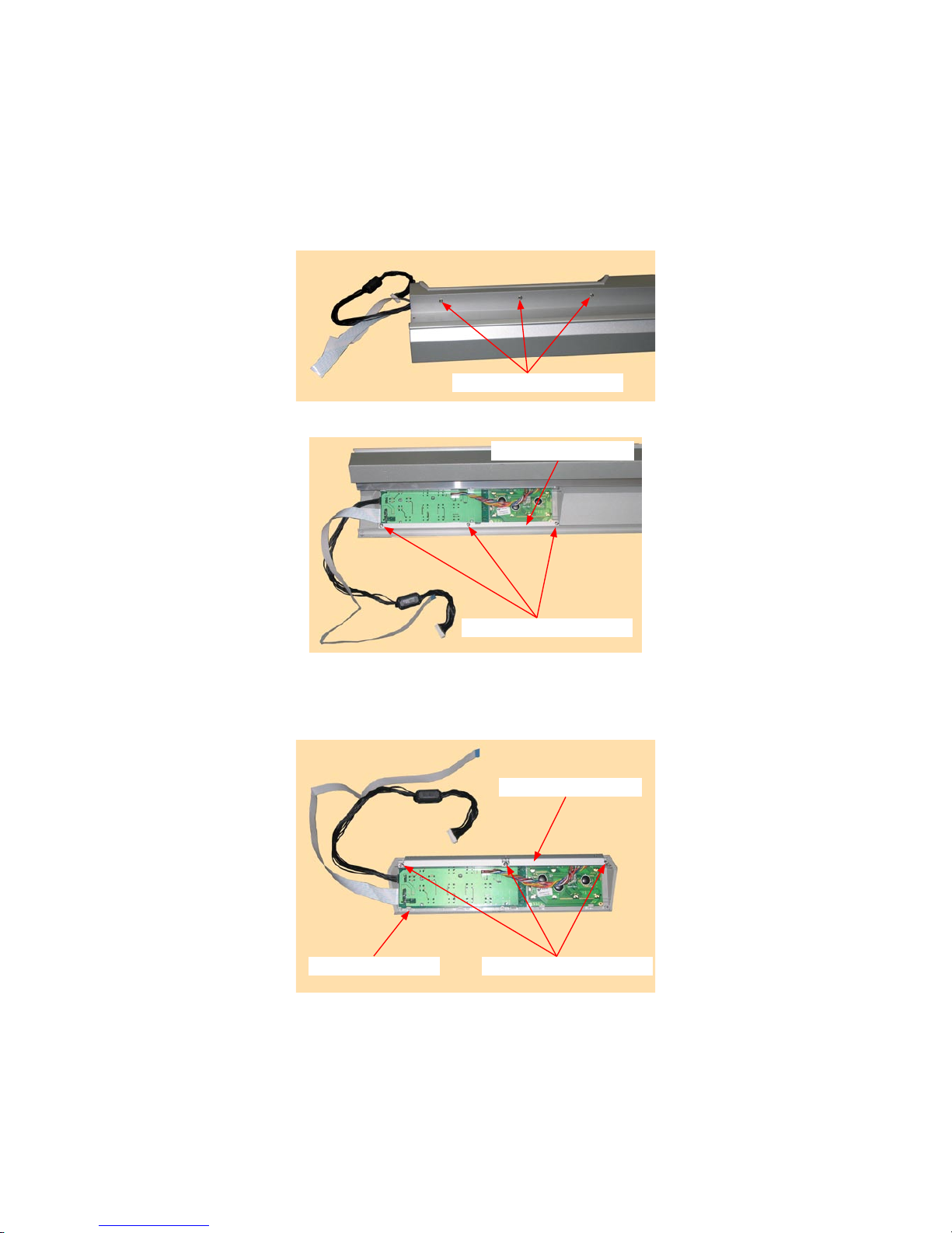
6.2.4 How to Replace the Control Panel Board, LCD Assembly
How to detach the control panel board, LCD assembly
(1) Detach the right side cover (see Subsection 6.1.1).
(2) Detach the center cover (see Subsection 6.1.3).
(3) Remove the three M3L6 binding head screws attaching the control panel board from the top of the
center cover.
M3L6 binding head screw
(4) Remove the three M3L6 binding head screws holding the control panel bracket and the center cover.
M3L6 binding head screw
Control panel bracket
(5) Detach the control panel board assembly from the center cover.
(6) Remove the three M3L6 binding head screws holding the control panel bracket to the control panel
cover.
M3L6 binding head screw
Control panel bracket
Control panel cover
Page 50
FC7000-UM-251-9370 6-12
6. DISASSEMBLY AND REASSEMBLY
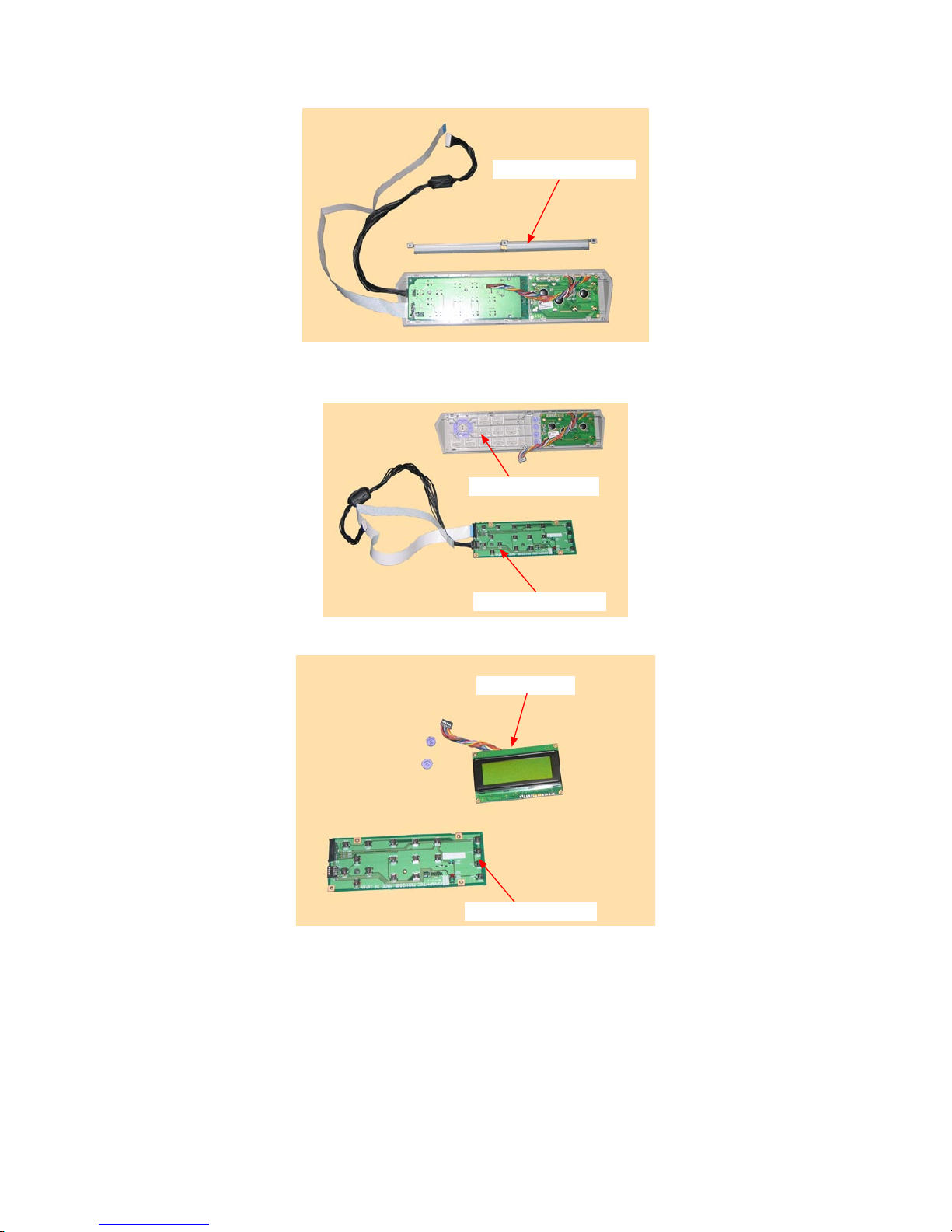
(7) Detach the control panel bracket from the control panel cover.
Control panel bracket
(8) Disconnect the cable from the LCD assembly.
(9) Detach the control panel board from the control panel cover.
Control panel cover
Control panel board
(10) Detach the LCD assembly from the control panel cover.
LCD assembly
Control panel board
How to reinstall the control panel board, LCD assembly
(1) Reattach the control panel board and LCD assembly in the reverse order in which they were detached.
Page 51
FC7000-UM-251-9370 6-13
6. DISASSEMBLY AND REASSEMBLY
6.2.5 How to Replace the Pen Block
How to detach the pen block
(1) Detach the right side cover (see Subsection 6.1.1).
(2) Detach the center cover (see Subsection 6.1.3).
(3) Loosen the two M3L6 binding head screws attaching the pen block cover.
M3L6 binding head screw
(4) Detach the pen block cover.
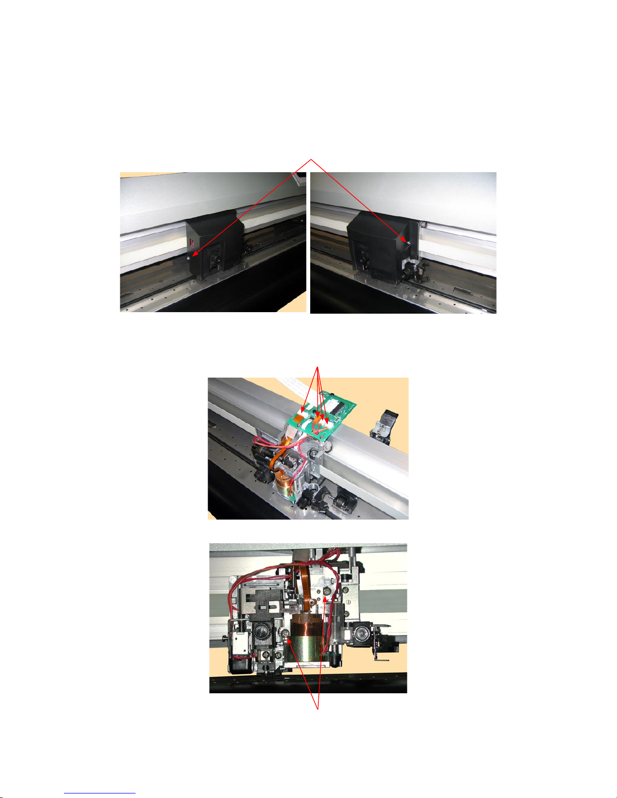
(5) Disconnect the cables from connector J502, J504, J505 and J506 on the Y-relay board.
Disconnect these cables from the connectors.
(6) Remove the two M4L6 binding head screws attaching the Y-relay block.
M4L6 binding head screw
Page 52
FC7000-UM-251-9370 6-14
6. DISASSEMBLY AND REASSEMBLY
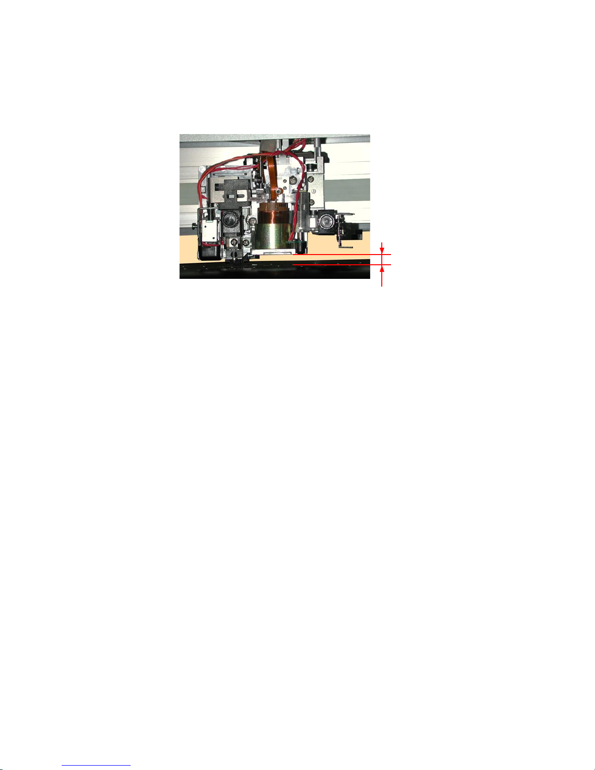
How to reinstall the pen block
(1) Attach the pen block to the Y-slider.
(2) Fasten the two M4L6 binding head screws to attach the pen block so that there is
a gap of 10 mm
between the bottom of the pen block and the cutting mat. Perform a visual check to make sure that
the pen block is not mounted at an angle.
10 mm
(3) Reattach the other parts in the reverse order in which they were detached.
(4) Perform the pen force adjustment (see Section 7.3.7).
(5) Perform the auto registration mark sensor sensitivity adjustment (see Section 7.3.9).
(6) Perform the auto registration mark sensor offset adjustment (see Section 7.3.10).
Page 53

FC7000-UM-251-9370 6-15
6. DISASSEMBLY AND REASSEMBLY
6.2.6 How to Replace the Y-belt
How to detach the Y-belt
(1) Detach the right and left side covers (see Subsection 6.1.1 and Subsection 6.1.2).
(2) Detach the center cover (see Subsection 6.1.3).
(3) Detach the pen block (see Subsection 6.2.5).
(4) Loosen the two M3L35 binding head screws adjusting the Y-belt tension.
M3L35 binding head screw
(5) Remove the four M3L6 binding head screws attaching the right and left Y-belt stopper plates to the
slider.
Y belt
M3L6 binding head screw
(6) Detach the Y-belt from the unit.
Page 54
FC7000-UM-251-9370 6-16
6. DISASSEMBLY AND REASSEMBLY
How to reinstall the Y-belt
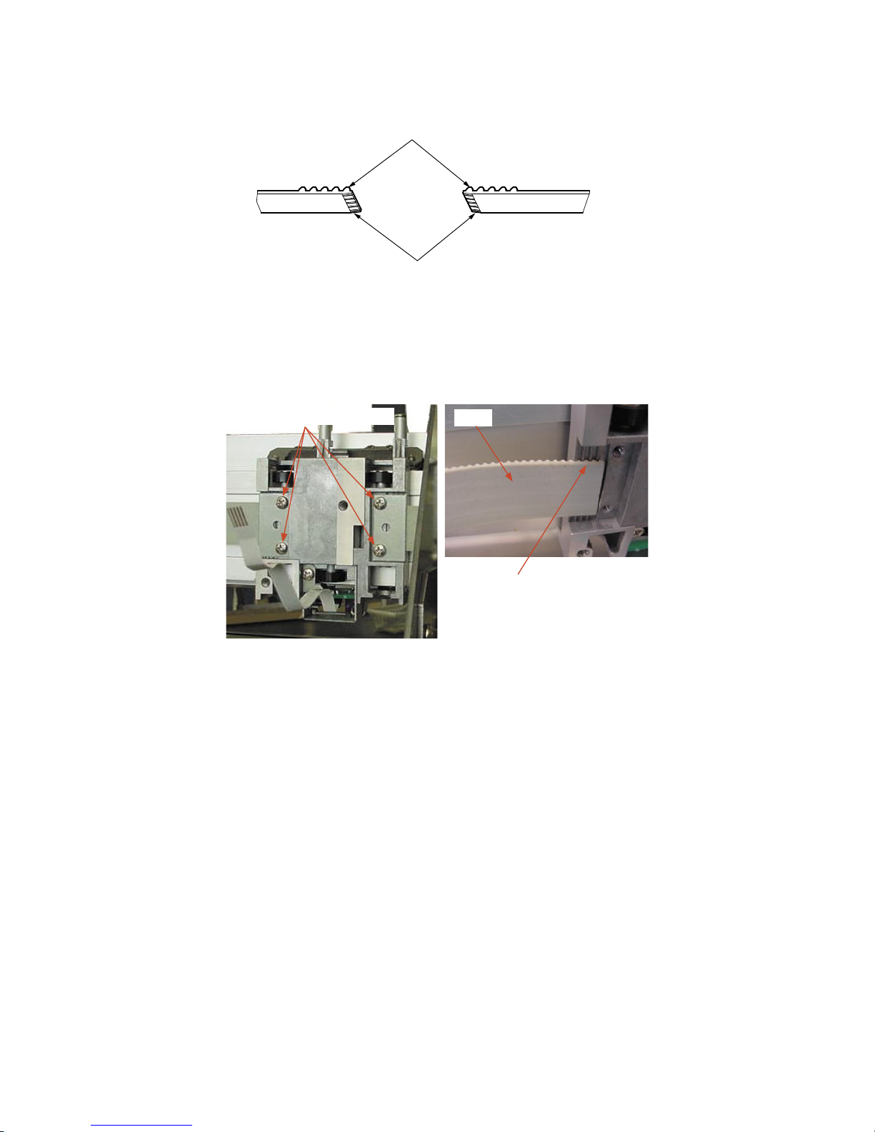
(1) Shave 2 to 3 mm off both ends of the Y-belt until the wire comes out as shown below.
Y-belt
Shave 2 to 3 mm off both ends of
the Y-belt until the wire comes out.
(2) Hang the Y-belt on both sides of the pulley.
(3) Attach both ends of the Y-belt to the Y-slider so that four notches of the Y-belt fi t into the Y-slider, then
attach with the Y-belt stopper plates removed in step (5) in the previous subsection.
M3L6 binding head screw
Y belt
Four notches of the Y-belt fi t into
the Y-slider.
(4) Attach the pen block (see Subsection 6.2.5).
(5) Reattach the other parts in the reverse order in which they were detached.
(6) Perform the Y-belt tension adjustment. (see Subsection 7.2.1).
Page 55
FC7000-UM-251-9370 6-17
6. DISASSEMBLY AND REASSEMBLY
6.2.7 How to Replace the Pinch Roller Sensor
How to detach the pinch roller sensor
(1) Detach the center cover (see Subsection 6.1.3).
(2) Detach the pen block (see Subsection 6.2.5).
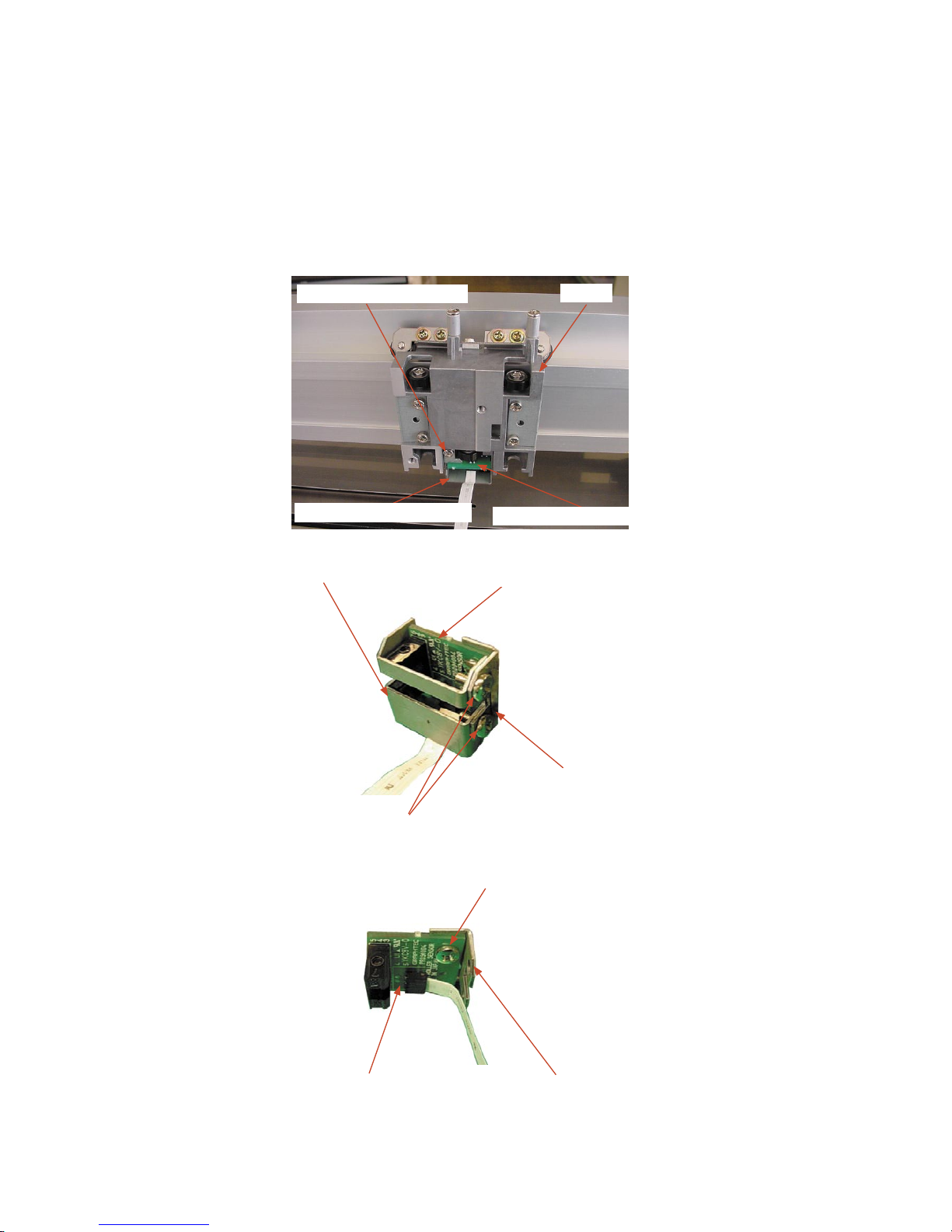
(3) Disconnect the pinch roller fl exible cable from the Y-relay board.
(4) Remove the pinch roller fl exible cable that is attached with double-sided adhesive tape to the Y-slider.
(5) Remove the M3L6 binding head screw attaching the pinch roller sensor bracket to the slider.
Y slider
M3L6 binding head screw
Pinch roller sensor bracket
Pinch roller sensor board
(6) Remove the two M3L6 binding head screws attaching the pinch roller sensor guard.
Pinch roller sensor guard
M3L6 binding head screw
Pinch roller sensor bracket
Pinch roller sensor board
(7) Remove the M3L6 binding head screw attaching the pinch roller sensor board.
M3L6 binding head screw
Pinch roller sensor bracketPinch roller sensor board
(8) Disconnect the pinch roller fl exible cable from the pinch roller sensor board.
Page 56

FC7000-UM-251-9370 6-18
6. DISASSEMBLY AND REASSEMBLY
How to reinstall the pinch roller sensor
(1) Attach the pinch roller bracket to the pinch roller sensor board.
(2) Connect the pinch roller flexible cable to the pinch roller sensor board.
(3) Attach the pinch roller sensor guard to the pinch roller sensor board bracket.
(4) Attach the pinch roller bracket to the Y-slider.
Fit the top and left edges of the pinch roller bracket to the Y-slider as shown in the figure below.
M3L6 binding head screw
Pinch roller sensor bracket
(5) Attach the pen block (see Subsection 6.2.5).
(6) Reattach the other parts in the reverse order in which they were detached.
Page 57

FC7000-UM-251-9370 6-19
6. DISASSEMBLY AND REASSEMBLY
6.2.8 How to Replace the Y-relay Board
How to detach the Y-relay board
(1) Detach the center cover (see Subsection 6.1.3).
(2) Remove the two plastic rivets attaching the fl exible cable holding plate.
Plastic rivet
Flexible cable holding plate
(3) Disconnect all the cables from the Y-relay board.
(4) Remove the two M3L35 binding head screws attaching the Y-relay board.
M3L35 binding head screw
(5) Detach the Y-relay board from the Y-slider.
How to reinstall the Y-relay board
(1) Reattach the Y-relay board in the reverse order in which it was detached.
Page 58

FC7000-UM-251-9370 6-20
6. DISASSEMBLY AND REASSEMBLY
6.2.9 How to Replace the Cam Sensor
How to detach the cam sensor
(1) Detach the right side cover (see Subsection 6.1.1).
(2) Disconnect the cable from the cam sensor.
M3L6 binding head screw
Cam sensor
(3) Remove the M3L6 binding head screw attaching the cam sensor.
How to reinstall the cam sensor
(1) Reattach the cam sensor in the reverse order in which it was detached.
Page 59
FC7000-UM-251-9370 6-21
6. DISASSEMBLY AND REASSEMBLY
6.2.10 How to Replace the Y-motor
How to detach the Y-motor
(1) Detach the right side cover (see Subsection 6.1.1).
(2) Disconnect the Y-motor cables from connector J7 and J13 on the main board.
(3) Loosen the two M3L4WP set screws to detach the Y-motor pulley.
Y motor
M3L6 binding head screw
M3L4WP set screw
Y motor pulley
(4) Remove the four M3L6 binding head screws holding the Y-motor.
(5) Detach the Y-motor pulley, then detach the Y-motor.
How to reinstall the Y-motor
(1) Attach the Y-motor to the Y-motor bracket.
(2) Hang the Y-drive belt on the Y-motor pulley and the Y-idler pulley.
(3) Attach the Y-motor pulley to the Y-motor.
(4) Tighten the two M3L4WP set screws that hold the Y-motor pulley.
(5) Spread a suitable quantity of Loctite 222 on the two M3L4WP set screws that hold the Y-motor pulley.
(6) Spread a suitable quantity of the Shinetu silicon grease G501 on the Y-motor pulley and Y-idler pulley.
(7) Perform the Y-drive belt tension adjustment. (see Subsection 7.2.2).
(8) Reattach the other parts in the reverse order in which they were detached.
Page 60

FC7000-UM-251-9370 6-22
6. DISASSEMBLY AND REASSEMBLY
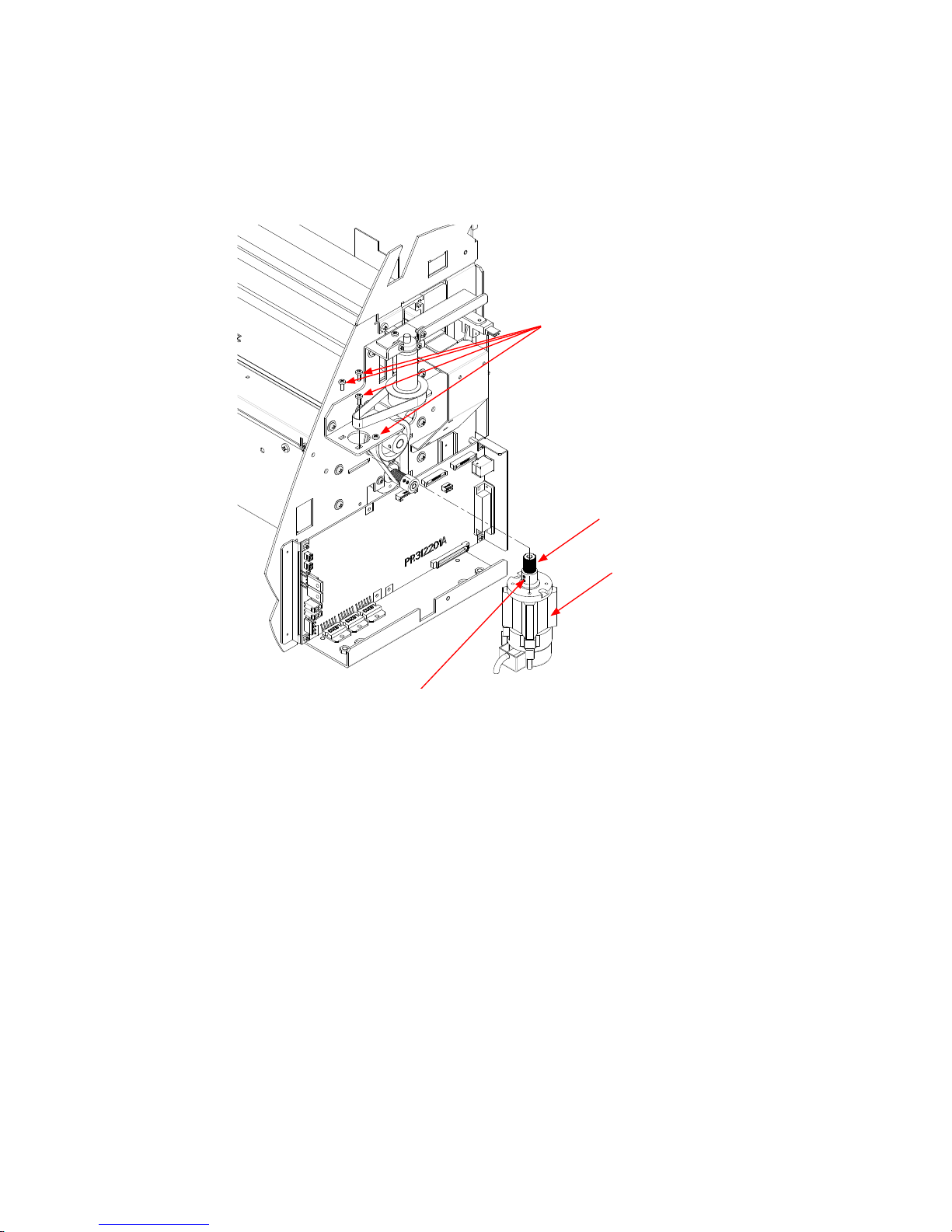
6.2.11 How to Replace the X-motor
How to detach the X-motor
(1) Detach the right side cover (see Subsection 6.1.1).
(2) Detach the main board (see Subsection 6.2.12).
(3) Loosen the two M3L4WP set screws holding the X-motor pulley, then detach the X-motor pulley.
M3L6 binding head screw
M3L4WP set screw
X motor pulley
X motor
(4) Remove the three M3L6 binding head screws holding the X-motor, then detach the X-motor.
How to reinstall the X-motor
(1) Attach the X-motor to the right side plate.
(2) Hang the X-drive belt on the X-drive pulley.
(3) Attach the X-motor pulley to the X-motor.
(4) Tighten the two M3L4WP set screws that hold the X-motor pulley.
(5) Spread a suitable quantity of Loctite 222 on the two M3L4WP set screws that hold the X-motor pulley.
(6) Perform the X-drive belt tension adjustment. (see Subsection 7.2.3).
(7) Tighten the mounting screws that hold the X-motor.
(8) Spread a suitable quantity of the Shinetu silicon grease G501 on the X-motor pulley.
(9) Move the X-drive pulley and check the tension of the X-drive belt.
(10) Reattach the other parts in the reverse order in which they were detached.
Page 61

FC7000-UM-251-9370 6-23
6. DISASSEMBLY AND REASSEMBLY
6.2.12 How to Replace the Main Board
How to detach the main board
(1) Detach the right side cover (see Subsection 6.1.1).
(2) Disconnect all the cables and flexible cables from their connectors on the main board.
(3) Remove the four M3L6 binding head screws holding the main board to the chassis.
(4) Detach the main board from the chassis.
M3L6 binding head screw
Main board
How to reinstall the main board
(1) Reattach in the reverse order in which it was detached.
(2) Perform any adjustments required (see Section 7.1).
Page 62

FC7000-UM-251-9370 6-24
6. DISASSEMBLY AND REASSEMBLY
6.2.13 How to Replace the Vacuum Fan
How to detach the vacuum fan
(1) Detach the front guide (see Subsection 6.1.4).
(2) Disconnect the vacuum fan from the relay connector.
Relay connector
Vacuum fan
(3) Use a long screwdriver to remove the two M3L35 binding head screws holding the vacuum fan as shown
in the figure below.
Vacuum fan
(4) Detach the vacuum fan.
How to reinstall the vacuum fan
(1) Reattach in the reverse order in which it was detached.
Page 63

FC7000-UM-251-9370 6-25
6. DISASSEMBLY AND REASSEMBLY
6.2.14 How to Replace the Drive Roller
How to detach the drive roller
(1) Detach the right and left side covers (see Subsection 6.1.1).
(2) Detach the front guide and rear guide (see Subsection 6.1.4 and Subsection 6.1.5).
(3) Detach the rear and front writing panels. (see Subsection 6.1.6 and Subsection 6.1.7).
(4) Loosen the three M3L6 binding head screws holding the X-motor to loosen the X drive belt.
(5) Remove the two M3L4WP set screws holding the X-drive pulley and detach the X-drive pulley from the
drive roller.
M3L6 binding head screw
M3L4WP set screw
X motor drive pulley
X motor
X drive belt
(6) Remove the X drive belt from the X-motor pulley.
(7) Remove the M3L6 binding head screws holding the bearing covers and detach the bearing covers from
the pillow blocks. (Don’t remove the M3L6 binding head screws holding the pillow blocks.)
Drive roller assembly
M3L6 binding head screw
Pillow block
Bearing cover
(8) Slide out the X-drive roller to the left side and detach the X drive roller assembly from the unit.
Page 64

FC7000-UM-251-9370 6-26
6. DISASSEMBLY AND REASSEMBLY
How to reinstall the drive roller
(1) Reattach in the reverse order in which it was detached.
(2) Spread a suitable quantity of Loctite 222 on the two M3L4WP set screws holding the X-drive pulley.
(3) Perform the X-drive belt tension adjustment. (see Subsection 7.2.3).
(4) Spread a suitable quantity of the Shinetu silicon grease G501 on the X-motor pulley.
(5) Move the X-drive pulley and check the tension of the X-drive belt.
(6) Reattach the other parts in the reverse order in which they were detached.
Page 65

FC7000-UM-251-9370 6-27
6. DISASSEMBLY AND REASSEMBLY
6.2.15 How to Replace the Cutting Mat
How to detach the cutting mat
(1) Peel off the cutting mat from the cutting mat base.
How to reinstall the cutting mat
(1) Clean the surface of the cutting mat base with alcohol where the cutting mat was attached.
(2) Attach the new cutting mat to the cutting mat base.
(3) Make sure that there is no air between the cutting mat and the cutting mat base.
Page 66
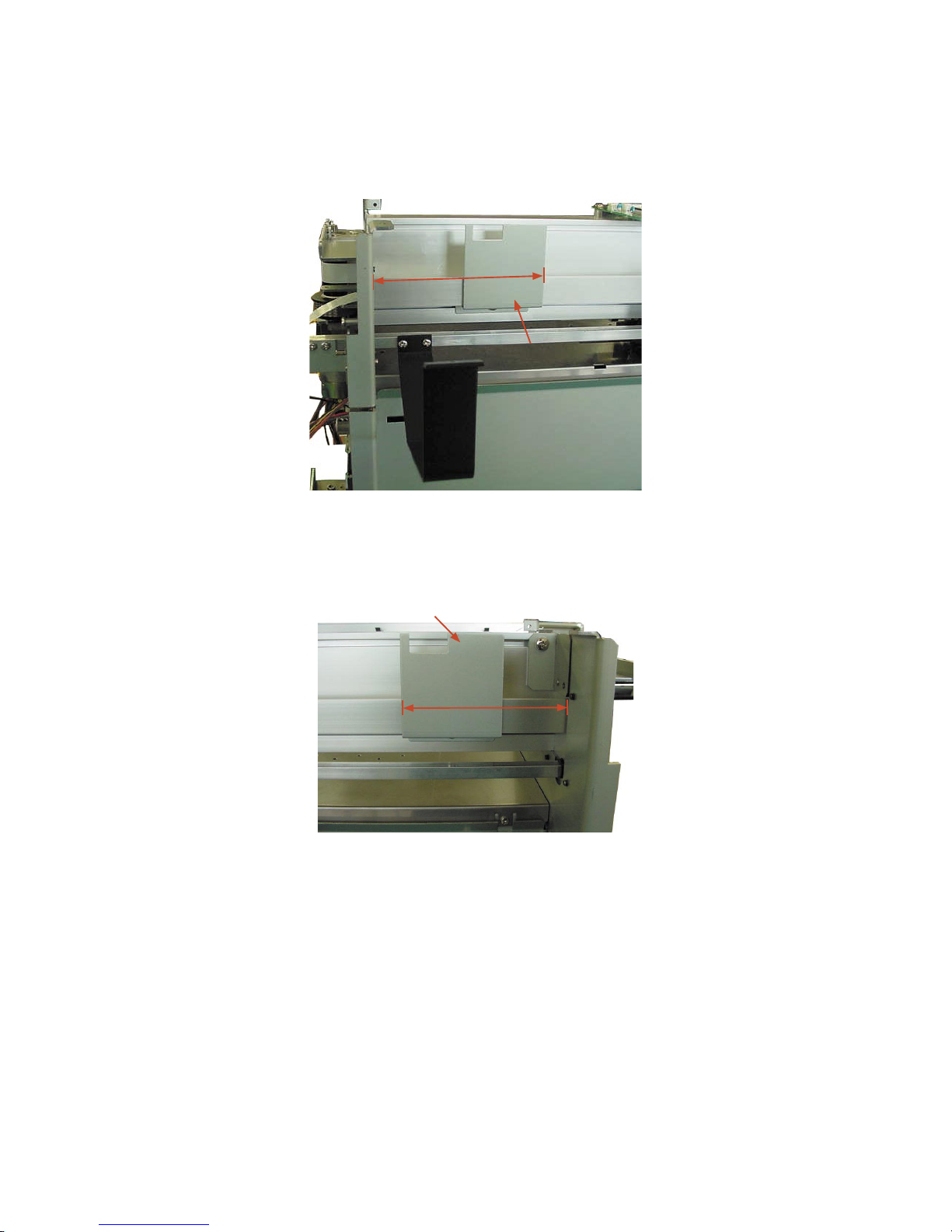
FC7000-UM-251-9370 6-28
6. DISASSEMBLY AND REASSEMBLY
6.2.16 Home Dog Position
Home dog position
Adjust the home dog position when you remove or replace the dog as shown below.
If you have an error about the pinch roller position, confi rm position of this dog.
115 mm
Home position dog
6.2.17 Cross Cutter Dog Position
Cross cutter dog position
Adjust the cross cutter position dog when you remove or replace the dog as shown below.
91 mm
Cross cutter position dog
Page 67

FC7000-UM-251-9370 7-1
7. ADJUSTMENT
7. ADJUSTMENTS
7.1 List of Items Requiring Readjustment
If you replaced any of the units listed in the table below or altered their sensor positions, be sure to readjust
the corresponding items.
Unit name
Item
Main board
Light
pointer
Pen block
Pinch roller
sensor
X,Y motor Drive roller
X,Y Motor
drive belt
Auto
registration
mark
sensor
NOV-RAM clear
M
Pen force adjustment M M
Distance adjustment M M M
Auto registration mark sensor
adjustment
N N N M
Light pointer adjustment N M N
Firmware upgrade M
Belt tension adjustment M M M
Pinch roller pressure adjustment M
2-Pen option adjustment N N
DIP switch setting
N
Servo gain adjustment N N
No mark: Unnecessary M: Must always be adjusted N: To be adjusted as necessary
Note: The main board must have the latest version of firmware unless otherwise specified.
Page 68
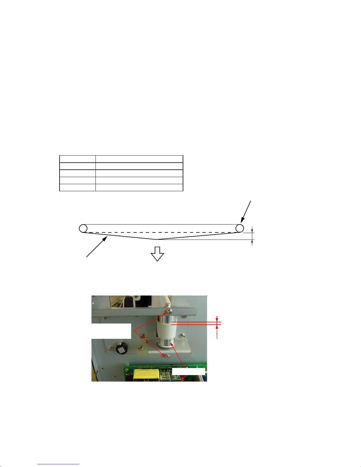
FC7000-UM-251-9370 7-2
7. ADJUSTMENT
7.2 Mechanical Adjustments
7.2.1 Y-Belt Tension Adjustment
How to adjust the Y-belt tension
Belt tension adjustment is required to set proper tension of the belt to maintain machine performance, reduce
overshoot, and correct any out-of-phase condition in the Y-axis.
(1) Detach the right side cover (see Subsection 6.1.1).
(2) With the Y-slider on the Y-rail and the belt attached, adjust the Y-tension pulley adjustment screws that
hold the Y-tension pulley onto the left side plate in order to tighten the Y-slider belt. Do not over-tighten.
Move the Y-slider from left to right several times to verify that the tension is set correctly.
(3) Move the Y-slider all the way to the right and pull the belt 20 mm towards the center using a force
gauge. Adjust the Y-tension pulley adjustment screws evenly until the tension reads as follows:
Specification of the Belt Tension
Model Force gauge reading specification
FC7000-75 700 g+50
FC7000-100 700 g+50
FC7000-130 700 g+50
FC7000-160 700 g+50
20 mm
700 g + 50g
Y idler pulley
Y belt
(4) Verify that the Y-slider belt is centered and does not move up and down when the Y-slider is moved from
left to right several times. The Y-slider belt should not move up and down more than 1.5 mm.
The Y-slider belt should
not move up and down
more than 1.5 mm.
Y idler pulley
Y-tension pulley
adjustment screws
(5) If the Y-slider belt continues to move up and down or exhibits less clearance, re-adjust the Y-tension
pulley adjustment screws and check the belt tension again.
(6) Reattach the right side cover.
Page 69
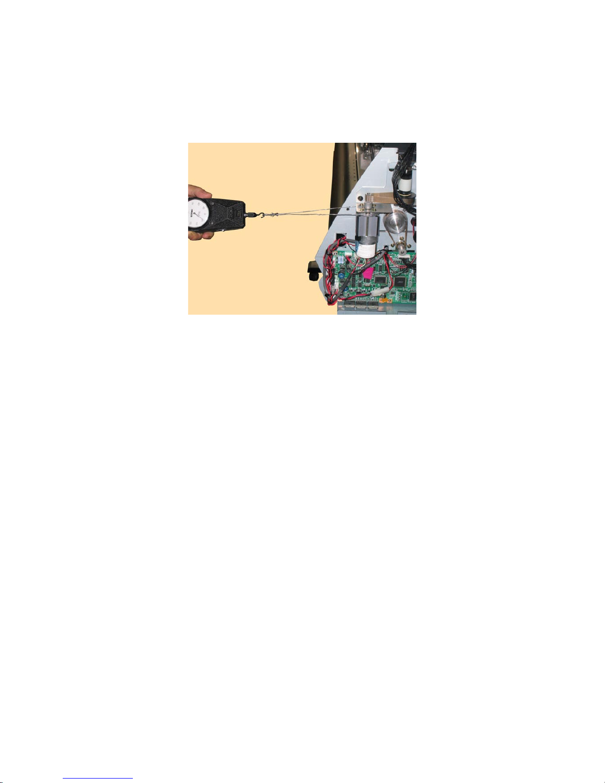
FC7000-UM-251-9370 7-3
7. ADJUSTMENT
7.2.2 Y-Drive Belt Tension Adjustment
How to adjust the Y-Drive belt tension
(1) Detach the right side cover (see Subsection 6.1.1).
(2) Loosen the four M3L6 binding head screws that hold the Y-motor.
(3) Use the force gauge to pull the Y-drive motor pulley flange with a 2.25 kg force.
(4) Tighten the four M3L6 binding head screws that hold the Y-motor.
(5) Spread a suitable quantity of the Shinetu silicon grease G501 on the Y-motor pulley.
(6) Move the pen block and check the tension of the Y-drive belt.
(7) Reattach the right side cover.
Page 70

FC7000-UM-251-9370 7-4
7. ADJUSTMENT
7.2.3 X-Drive Belt Tension Adjustment
How to adjust the X-Drive belt tension
(1) Detach the right side cover (see Subsection 6.1.1).
(2) Loosen the three M3L6 binding head screws that hold the X-motor.
(3) Use the force gauge to push the X-drive motor pulley fl ange with a 2.25 kg force as shown in the fi gure
below.
M3L6 binding head screw
(4) Tighten the mounting screws that hold the X-motor.
(5) Spread a suitable quantity of the Shinetu silicon grease G501 on the X-motor pulley.
(6) Move the X-drive pulley and check the tension of the X-drive belt.
(7) Reattach the right side cover.
Page 71

FC7000-UM-251-9370 7-5
7. ADJUSTMENT
7.2.4 Pinch Roller Pressure Adjustment
How to adjust the pinch roller pressure
(1) Detach the center cover (see Subsection 6.1.3).
(2) Change the hold-down force switching lever to the Strong position.
Strong hold-down forceWeak hold-down force
(3) Place the pinch roller on the grit roller.
(4) Sandwich the stainless steel plate jig as shown in the figure below and catch the push pressure wire jig
on the pinch roller shaft.
(5) Pull the wire of the push pressure wire jig in the direction of the arrow with the 10 kgf push-pull gauge.
Note *Be sure to pull in the correct direction.
*Be sure to pull at the angle shown in the figure above (the angle at which the wire jig is almost
touching the Y rail).
(6) Read out the value at which the stainless steel plate jig slips out.
The pinch roller pressure should be 6.5 kg ±0.25 force.
The pressure difference between each pinch roller should be less than 0.4 kg.
Page 72

FC7000-UM-251-9370 7-6
7. ADJUSTMENT
(7) If the measurement does not match this value, adjust the pinch roller pressure adjustment screw and
check again.
Pinch roller pressure adjustment screw
(8) Reattach the center cover.
Page 73

FC7000-UM-251-9370 7-7
7. ADJUSTMENT
7.3 Electrical Adjustments
7.3.1 Position of the DIP Switch and Connectors
FC7000
J16
J13
J12
J24
J23
J2
J3
J1
J18
F1
J20J17
J5
SW1
J4 J6 J7 J9 J8
Page 74

FC7000-UM-251-9370 7-8
7. ADJUSTMENT
FC7000MK2
J16
J13
J12
J61
J21
J2
J3
J1
J60
F1
F5
F4
J20J17
J5
SW1
J4
J6
J7
J9
J8
Page 75

FC7000-UM-251-9370 7-9
7. ADJUSTMENT
7.3.2 DIP Switch Settings
The black circles indicate the position of each switch.
Factory presets (Normal Mode)
FC7000MK2-60 FC7000MK2-60 (2-Pen Model)
SW1
1 2 3 4 5 6 7 8
ON
OFF
SW1
1 2 3 4 5 6 7 8
ON
OFF
FC7000-75/MK2-75 FC7000-75/MK2-75 (2-Pen Model)
SW1
1 2 3 4 5 6 7 8
ON
OFF
SW1
1 2 3 4 5 6 7 8
ON
OFF
FC7000-100/MK2-100 FC7000-100/MK2-100 (2-Pen Model)
SW1
1 2 3 4 5 6 7 8
ON
OFF
SW1
1 2 3 4 5 6 7 8
ON
OFF
FC7000-130/MK2-130 FC7000-130/MK2-130 (2-Pen Model)
SW1
1 2 3 4 5 6 7 8
ON
OFF
SW1
1 2 3 4 5 6 7 8
ON
OFF
FC7000-160/MK2-160 FC7000-160/MK2-160 (2-Pen Model)
SW1
1 2 3 4 5 6 7 8
ON
OFF
SW1
1 2 3 4 5 6 7 8
ON
OFF
NOV-RAM Clear
FC7000Mk2-60 FC7000Mk2-60 (2-Pen Model)
SW1
1 2 3 4 5 6 7 8
ON
OFF
SW1
1 2 3 4 5 6 7 8
ON
OFF
FC7000-75/MK2-75 FC7000-75/MK2-75 (2-Pen Model)
SW1
1 2 3 4 5 6 7 8
ON
OFF
SW1
1 2 3 4 5 6 7 8
ON
OFF
FC7000-100/MK2-100 FC7000-100/MK2-100 (2-Pen Model)
SW1
1 2 3 4 5 6 7 8
ON
OFF
SW1
1 2 3 4 5 6 7 8
ON
OFF
FC7000-130/MK2-130 FC7000-130/MK2-130 (2-Pen Model)
SW1
1 2 3 4 5 6 7 8
ON
OFF
SW1
1 2 3 4 5 6 7 8
ON
OFF
FC7000-160/MK2-160 FC7000-160/MK2-160 (2-Pen Model)
SW1
1 2 3 4 5 6 7 8
ON
OFF
SW1
1 2 3 4 5 6 7 8
ON
OFF
Page 76

FC7000-UM-251-9370 7-10
7. ADJUSTMENT
7.3.3 Checking the Power Supply Board Voltage Levels
(1) Detach the left side cover (see Subsection 6.1.2).
(2) Turn on the power switch and then check the voltage levels.
CN1
CN2
Power supply board
(3) The output voltage levels of the pins are shown in the table below.
Connector name Pin No. Name Output voltage
CN1
1 AC (L)
AC power voltage (Depends on
the supply voltage.
2 Not used
3 AC (N)
CN2
1 +40 V DC +40V
2 +40 V DC +40V
3 GND 4 GND -
Page 77

FC7000-UM-251-9370 7-11
7. ADJUSTMENT
7.3.4 Explanation of the Values of the Main Board Settings
(Default factory settings)
The default factory settings are recorded in the location shown below.
The default factory settings
are recorded here.
The contents of an example record are shown below.
25 47 100 228 346
X= 0 X= 80 X= -
Y= 4 Y= 50 Y= -
Explanation of the values
Pen force values
10 g 40g 120 g 300 g 450 g (400g)
Distance adjustment values Gain adjustment values Auto registration mark position adjustment values
X X X
Y Y Y
You can input the same values when you have replaced the main board without making any adjustments.
If you have changed any values by making adjustments, record those values for the next maintenance check.
Page 78

FC7000-UM-251-9370 7-12
7. ADJUSTMENT
7.3.5 Clearing the Non-Volatile RAM
When you replace the main board, you must clear the Non-Volatile RAM (NOV-RAM).
If you clear the Non-Volatile RAM, you will lose the setup parameters for each adjustment.
Input the adjustment values to the main board after you clear the Non-Volatile RAM.
How to clear the Non-Volatile RAM.
(1) Set SW1 to the NOV-RAM clear mode as shown below.
FC7000MK2-60 FC7000MK2-60 (2-Pen Model)
SW1
1 2 3 4 5 6 7 8
ON
OFF
SW1
1 2 3 4 5 6 7 8
ON
OFF
FC7000-75/MK2-75 FC7000-75/MK2-75 (2-Pen Model)
SW1
1 2 3 4 5 6 7 8
ON
OFF
SW1
1 2 3 4 5 6 7 8
ON
OFF
FC7000-100/MK2-100 FC7000-100/MK2-100 (2-Pen Model)
SW1
1 2 3 4 5 6 7 8
ON
OFF
SW1
1 2 3 4 5 6 7 8
ON
OFF
FC7000-130/MK2-130 FC7000-130/MK2-130 (2-Pen Model)
SW1
1 2 3 4 5 6 7 8
ON
OFF
SW1
1 2 3 4 5 6 7 8
ON
OFF
FC7000-160/MK2-160 FC7000-160/MK2-160 (2-Pen Model)
SW1
1 2 3 4 5 6 7 8
ON
OFF
SW1
1 2 3 4 5 6 7 8
ON
OFF
(2) Turn on the power to the plotter.
(3) The NOVRAM CLEAR START menu appears. The plotter immediately starts to clear the parameters on
the NOV-RAM, and then sets the default values.
NOVRAM CLEAR START
(4) When the programming is complete, the NOVRAM CLEAR END menu appears.
NOVRAM CLEAR END
(5) Turn off the power to the plotter.
Page 79

FC7000-UM-251-9370 7-13
7. ADJUSTMENT
(6) Return the SW1 setting to the normal mode as shown below.
FC7000MK2-60 FC7000MK2-60 (2-Pen Model)
SW1
1 2 3 4 5 6 7 8
ON
OFF
SW1
1 2 3 4 5 6 7 8
ON
OFF
FC7000-75/MK2-75 FC7000-75/MK2-75 (2-Pen Model)
SW1
1 2 3 4 5 6 7 8
ON
OFF
SW1
1 2 3 4 5 6 7 8
ON
OFF
FC7000-100/MK2-100 FC7000-100/MK2-100 (2-Pen Model)
SW1
1 2 3 4 5 6 7 8
ON
OFF
SW1
1 2 3 4 5 6 7 8
ON
OFF
FC7000-130/MK2-130 FC7000-130/MK2-130 (2-Pen Model)
SW1
1 2 3 4 5 6 7 8
ON
OFF
SW1
1 2 3 4 5 6 7 8
ON
OFF
FC7000-160/MK2-160 FC7000-160/MK2-160 (2-Pen Model)
SW1
1 2 3 4 5 6 7 8
ON
OFF
SW1
1 2 3 4 5 6 7 8
ON
OFF
Page 80

FC7000-UM-251-9370 7-14
7. ADJUSTMENT
7.3.6 How to Enter the Adjustment Menu
(1) Turn on the power while pressing the TEST and ENTER keys.
Or
After turning on the power, press the TEST key and the ENTER key simultaneously within 2 seconds.
(2) Load a sheet of paper in the plotter.
(3) The plotter displays the menu shown below.
CONDITION 1 12
20
READY 4
PEN
(4) Press the MENU key to display the menu shown below.
SENSOR TEST
KEY TEST
PEN FORCE
XY GAIN
Page 81
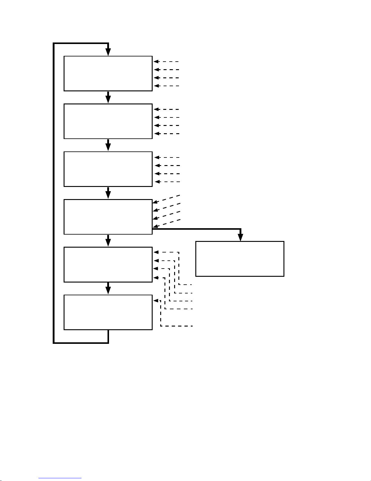
FC7000-UM-251-9370 7-15
7. ADJUSTMENT
Adjustment Menu List
RM SENSOR POS ADJ
C-CUTTER POS ADJ
2 PEN THRESHOLD
C-CUTTER THRESHOLD
LED PEN POS ADJ
2 PEN TYPE MACHINE
RM SENSOR LEVEL
RM DEBUG>
CAM POS CHECK
MEDIA DEFAULT
LED PEN TEST
PAPER WEIGHT TEST
CROSS CUT SPEED
1/2 PEN POSITION ADJ
DISTANCE ADJUST
2 PEN EXCHANGE ADJ
RM SENSOR LEVEL ADJ
SENSOR TEST
KEY TEST
PEN FORCE
XY GAIN
R-MARK MONITOR X
R-MARK MONITOR Y
RMS SENSING SPEED
RMS THRESHOLD
Sensor test.
Key test.
Pen pressure adjustment.
Gain adjustment. (Not used.)
1 and 2 pen position adjustment for the 2-pen model.
Distance adjustment.
2-pen exchange adjustment for the 2-pen model.
Registration mark sensor level adjustment.
Registration mark sensor position adjustment.
Cross cutter position adjustment.
2-pen height position adjustment.(Not used.)
Cross cutter height position adjustment.(Not used.).
Light pointer position adjustment.
2-pen type confirmation.
Registration sensor level adjustment.
Debug menu.(Not used.)
Not used.
Not used.
Not used.
Not used.
Not used.
Page 82

FC7000-UM-251-9370 7-16
7. ADJUSTMENT
7.3.7 Adjusting the Pen Force
This adjustment will set the pen force.
If you replace the main board, use the following procedure to input the recorded adjustment values.
If you replace the moving coil and/or the pen block assembly, you must adjust the pen force using the
following procedure.
How to adjust the pen force
(1) Mount a 0.9 mm diameter cutter pen in the pen holder.
(2) Load a sheet of paper in the plotter.
(3) Enter the adjustment menu (see Section 7.3.6).
(4) Press the MENU key to display the menu shown below.
SENSOR TEST
KEY TEST
PEN FORCE
XY GAIN
(5) Press the F3 key to display the menu shown below.
Don’t select AUTO!
PEN PRESS ADJUST
AUTO with gauger>
MANUAL>
(6) Press the F4 key to display the menu shown below.
PRS 10g D/A= 20
(7) The pen is lowered. If you have replaced the moving coil and/or the pen block assembly, use the force
gauge to measure the actual force. If you have only replaced the main board, input the adjustment
values that were recorded.
Use the UP ARROW key or DOWN ARROW key to change the force setting. The number on the LCD
will increase or decrease. If you have replaced the moving coil and/or the pen block assembly, measure
the actual pen force again.
If you replaced the moving coil and/or the pen block assembly, adjust the 10g-pen force. If the measured
value is within the specification range (10±2g) or if you have input the recorded value, press the ENTER
key to store the setting. The next specified pen force appears.
(8) Adjust the 40g-pen force. If the measured value is within the specification range (40±4g) or if you
have input the recorded value, press the ENTER key to store the setting. The next specified pen force
appears.
(9) Adjust the 120g-pen force. If the measured value is within the specification range (120±10g) or if you
have input the recorded value, press the ENTER key to store the setting. The next specified pen force
appears.
Page 83

FC7000-UM-251-9370 7-17
7. ADJUSTMENT
(10) Adjust the 300g-pen force. If the measured value is within the specification range (300±20g) or if you
have input the recorded value, press the ENTER key to store the setting. The next specified pen force
appears.
(11) Adjust the 450 (400) g-pen force. If the measured value is within the specification range (FC7000: 450
±20g, FC7000Mk2 and FC7000 with new main board, 9 Series: 400±20g ) or if you have input the
recorded value, press the ENTER key to store the setting.
Note: When adjusting the pen force, it is important to do it quickly. Delaying the pen force adjustment
changes the temperature of the actuator and causes artificially lower readings. When this happens the
actual pen force may be higher than the specification. This is especially true for the upper pen force
adjustment.
(12) Press the NEXT key to complete this adjustment.
(13) Turn off the power to exit from the adjustment menu.
Specification of the actual pen force
Specified pen force
Actual force range
FC7000
FC7000 with new
Main boaed
FC7000MK2 9 Series
10g 8 to 12g 8 to 12g 8 to 12g 8 to 12g
40g 36 to 44g 36 to 44g 36 to 44g 36 to 44g
120g 110 to 130g 110 to 130g 110 to 130g 110 to 130g
300g 280 to 320g 280 to 320g 280 to 320g 280 to 320g
450g (400g) 430 to 470g 380 to 420g 380 to 420g 380 to 420g
Page 84

FC7000-UM-251-9370 7-18
7. ADJUSTMENT
7.3.8 Adjusting the Distance Accuracy
This adjustment will set the distance accuracy.
If you replace the main board, use the following procedure to input the recorded adjustment values.
If you replace the drive roller, you must adjust the distance accuracy using the following procedure.
How to adjust the distance accuracy
(1) Enter the adjustment menu (see Section 7.3.6).
(2) Press the MENU key to display the menu shown below.
SENSOR TEST
KEY TEST
PEN FORCE
XY GAIN
(3) Load an A2 or larger size sheet of paper in the plotter. The paper color must be white, and it is
recommended that high-quality paper made for ink-jet printers be used.
(4) Mount a disposable ink pen (0.2 mm tip size) in the pen holder.
(5) Set the plotting conditions to the following settings:
Force: 12, Speed: 40, Quality: 1, Tool: Pen
(6) Lower the media set lever to raise the pinch rollers, and then raise the media set lever to detect the
paper size.
The menu shown below is displayed after the media set lever is raised.
CONDITION 12
40
READY 1
PEN
(7) Press the MENU key to display the menu shown below.
SENSOR TEST
KEY TEST
PEN FORCE
XY GAIN
(8) Press the NEXT key to display the menu shown below.
DISTANCE ADJUST
RM SENSOR LEVEL ADJ
1/2 PEN POSITION ADJ
DISTANCE ADJUST
2 PEN EXCHANGE ADJ
RM SENSOR LEVEL ADJ
1-PEN MODEL 2-PEN MODEL
Page 85
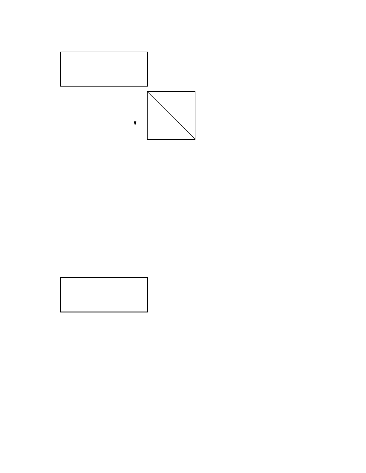
FC7000-UM-251-9370 7-19
7. ADJUSTMENT
(9) Press the F2 key to start the test. The plotter immediately plots the test pattern, and the following menu
appears.
DADJ.X= 0 Y= 0
+X
Y=300 mm
X=300 mm
(10) Remove the paper and measure the Y-axis distance. If you have replaced the main board only, use the
recorded values.
(11) Input the values using the POSITION keys.
Press the LEFT or RIGHT ARROW key to select the Y-axis or X-axis distance adjustment.
The UP and DOWN ARROW keys are used to change the Y-axis or X-axis adjustment value.
The formula of the input value is as follows:
Input value for X-axis = (300mm - measured X distance) x 10
Input value for Y-axis = (300mm - measured Y distance) x 10
For example:
If you measured 299.0mm for the Y-axis then input 10 for the adjustment value.
Adjustable range: -9.9 mm to +9.9mm , 0.1-mm steps
(12) Press the ENTER key to store the setting. The following menu appears.
XY LENG L=XXX.XX
The value of the XY LENG L is showing the calculated value, so you do not need to adjust this value.
(13) If you wish to complete this adjustment, press the NEXT key. If you wish to plot the adjusted test
pattern, press the ENTER key.
(14) Turn off the power to exit from the adjustment menu.
Page 86
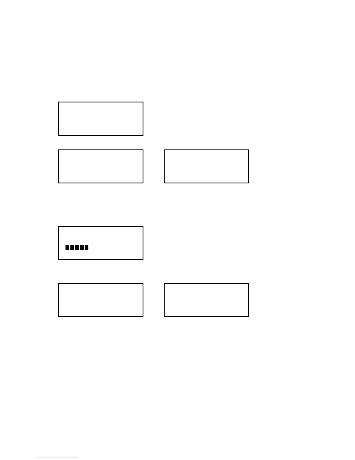
FC7000-UM-251-9370 7-20
7. ADJUSTMENT
7.3.9 Adjusting the Auto-Registration Mark Sensor Sensitivity
If you replace the main board, you need to adjust the sensitivity.
How to adjust the auto-registration mark sensor sensitivity
(1) Load an A4 (Letter) or larger size sheet of paper in the plotter. The paper color must be white, and it is
recommended that high-quality paper made for ink-jet printers be used.
(2) Enter the adjustment menu (see Section 7.3.6).
(3) Press the MENU key to display the menu shown below.
SENSOR TEST
KEY TEST
PEN FORCE
XY GAIN
(4) Press the NEXT key to display the menu shown below.
DISTANCE ADJUST
RM SENSOR LEVEL ADJ
1/2 PEN POSITION ADJ
DISTANCE ADJUST
2 PEN EXCHANGE ADJ
RM SENSOR LEVEL ADJ
1-PEN MODEL 2-PEN MODEL
(5) Press the F4 key to start the registration mark sensor gain adjustment. The plotter immediately adjusts
the registration mark sensor gain automatically. Press the ENTER key immediately to display the menu
shown below. The plotter displays the menu shown below while pressing the ENTER key is hold down.
50
Confirm that the output level is between 50 to 60.
(6) The plotter displays the menu shown below when this adjustment has been completed.
DISTANCE ADJUST
RM SENSOR LEVEL ADJ
1/2 PEN POSITION ADJ
DISTANCE ADJUST
2 PEN EXCHANGE ADJ
RM SENSOR LEVEL ADJ
1-PEN MODEL 2-PEN MODEL
(7) Turn off the power to exit from the adjustment menu.
Page 87

FC7000-UM-251-9370 7-21
7. ADJUSTMENT
7.3.10 Adjusting the Offset of the Auto-Registration Mark Sensor
If you replace the Auto-registration mark sensor or the main board, you need to adjust the offset.
How to adjust the auto-registration mark sensor
(1) Enter the adjustment menu (see Section 7.3.6).
(2) Press the MENU key to display the menu shown below.
SENSOR TEST
KEY TEST
PEN FORCE
XY GAIN
(3) Load an A2 or larger size sheet of paper in the plotter. The paper color must be white, and it is
recommended that high-quality paper made for ink-jet printers be used.
(4) Mount a disposable ink pen (0.2 mm tip size) in the pen holder.
(5) Set the plotting conditions to the following settings:
Force: 12, Speed: 40, Quality: 1, Tool: Pen
(6) Lower the media set lever to raise the pinch rollers, and then raise the media set lever to detect the
paper size.
The menu shown below is displayed after the media set lever is raised.
CONDITION 12
40
READY 1
PEN
(7) Press the MENU key to display the menu shown below.
SENSOR TEST
KEY TEST
PEN FORCE
XY GAIN
(8) Press the NEXT key until the menu shown below is displayed.
RM SENSOR POS ADJ
C-CUTTER POS ADJ
2 PEN THRESHOLD
C-CUTTER THRESHOLD
(9) Use the ARROW keys to move the pen to an open area to plot the adjustment pattern.
Page 88

FC7000-UM-251-9370 7-22
7. ADJUSTMENT
(10) Press the F1 key to plot the adjustment pattern shown below.
Plotted target mark
Adjustment lines
(11) The plotter immediately adjusts the registration mark sensor position automatically, and adds a vertical
line and a horizontal line to the scanned plotted pattern.
(12) Measure the offset between the lines and confirm that they are within 0.25 mm.
(13) Turn off the power to exit from the adjustment menu.
Page 89

FC7000-UM-251-9370 7-23
7. ADJUSTMENT
7.3.11 Adjusting the Cross Cutter Home Position
This adjustment will set the cross cutter home position value.
If you replace the main board, use the following procedure to input the recorded adjustment values.
How to adjust the cross cutter home position
(1) Enter the adjustment menu (see Section 7.3.6).
(2) Load an A3 or larger size sheet of paper in the plotter. The paper must cover the front and rear media
sensors.
(3) Lower the media set lever to raise the pinch rollers, and then raise the media set lever to detect the
paper size.
The menu shown below is displayed after the media set lever is raised.
CONDITION 12
40
READY 1
PEN
(4) Press the MENU key to display the menu shown below.
SENSOR TEST
KEY TEST
PEN FORCE
XY GAIN
(5) Press the NEXT key until the menu shown below is displayed.
RM SENSOR POS ADJ
C-CUTTER POS ADJ
2 PEN THREAHOLD
C-CUTTER THREAHOLD
(6) Press the F2 key to display the menu shown below.
The menu shown below is displayed after the paper size is detected.
SENSOR TEST
KEY TEST
PEN FORCE
XY GAIN
(7) Press the NEXT key until the menu shown below is displayed.
RM SENSOR POS ADJ
C-CUTTER POS ADJ
2 PEN THREAHOLD
C-CUTTER THREAHOLD
(8) Press the F2 key to display the menu shown below.
The pen head moves to the left side of the cross cutter home position.
C-CUTTER POS ADJ
20
CONFIRM>
Page 90

FC7000-UM-251-9370 7-24
7. ADJUSTMENT
(9) Confirm the gap between the cross cutter dog and the cross cutter release plate.
(10) Press the F4 key to confirm the gap.
(11) Adjust the gap to a value in the range of 0 mm to 0.2 mm.
Press the UP or DOWN ARROW key to adjust the gap.
(1 unit = 0.05 mm)
Cross cutter dog
Cross cutter release plate
0 to 0.2 mm
(12) Press the F4 key to confirm the gap.
If the cross cutter dog presses on the cutter release plate too much, a position alarm error will be
displayed.
At this time reduce the C-CUTTER POS ADJ value.
(13) Press the ENTER key to store the setting.
(14) Turn off the power to exit from the adjustment menu.
Page 91
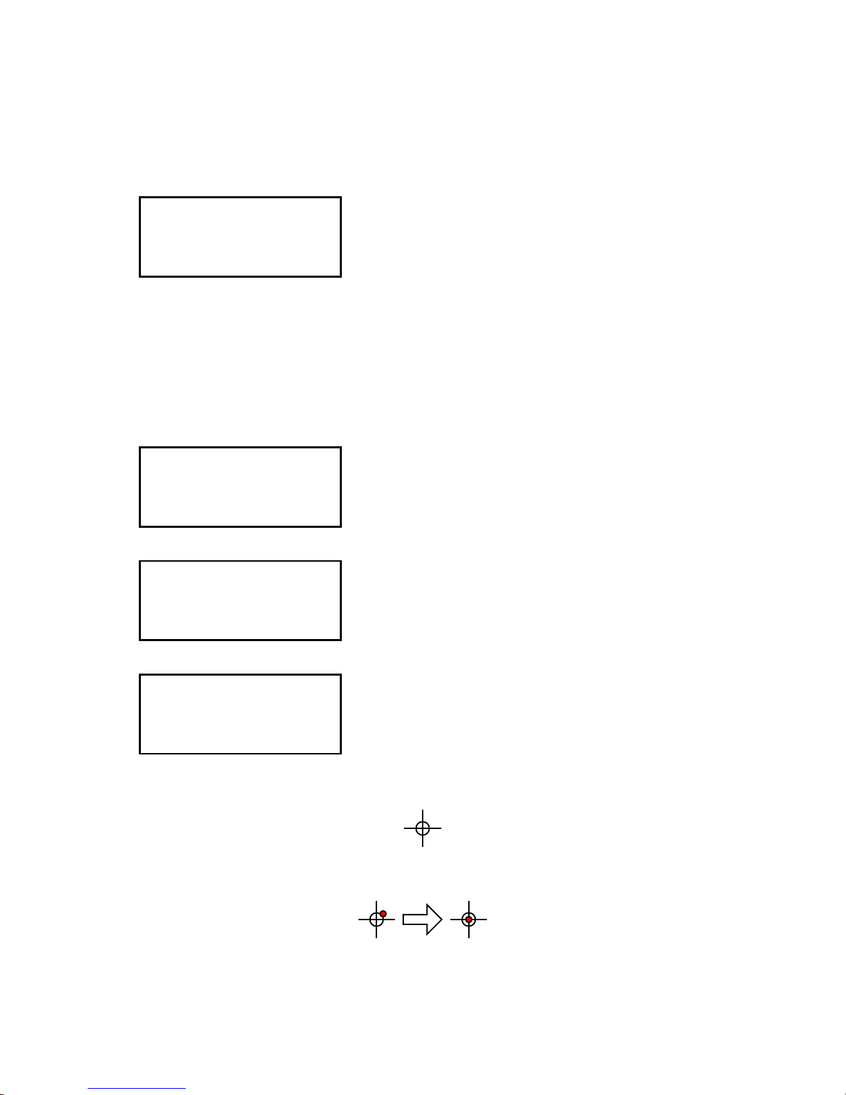
FC7000-UM-251-9370 7-25
7. ADJUSTMENT
7.3.12 Adjusting the Offset of the Light Pointer Position
If you replace the light pointer or the main board, you need to adjust the offset.
How to adjust the offset of the light pointer position
(1) Enter the adjustment menu (see Section 7.3.6).
(2) Press the MENU key to display the menu shown below.
SENSOR TEST
KEY TEST
PEN FORCE
XY GAIN
(3) Load an A2 or larger size sheet of paper in the plotter.
(4) Mount a disposable ink pen (0.2 mm tip size) in the pen holder.
(5) Set the plotting conditions to the following settings:
Force: 12, Speed: 40, Quality: 1, Tool: Pen
(6) Lower the media set lever to raise the pinch rollers, and then raise the media set lever to detect the
paper size.
The menu shown below is displayed after the media set lever is raised.
CONDITION 12
40
READY 1
PEN
(7) Press the MENU key to display the menu shown below.
SENSOR TEST
KEY TEST
PEN FORCE
XY GAIN
(8) Press the NEXT key until the menu shown below is displayed.
LED PEN POS ADJ
2 PEN TYPE MACHINE
RM SENSOR LEVEL
RM DEBUG
(9) Use the POSITION keys to move the pen to an open area to plot the adjustment pattern.
(10) Press the F1 key to plot the adjustment pattern shown below.
(11) Move the light pointer to the center of the adjustment pattern using the POSITION keys, and then press
the ENTER key to register the position.
(12) Turn off the power to exit from the adjustment menu.
Page 92

FC7000-UM-251-9370 7-26
7. ADJUSTMENT
7.3.13 Confirming the 2-Pen Model (2-pen model)
This setting will confirm that the plotter is a 2-pen model.
If you replace the main board, use the following procedure to make the 2-pen model setting.
(1) Load an A2 or larger size sheet of paper in the plotter.
(2) Enter the adjustment menu (see Section 7.3.6).
(3) Press the MENU key to display the menu shown below.
SENSOR TEST
KEY TEST
PEN FORCE
XY GAIN
(4) Press the NEXT key until the menu shown below is displayed.
LED PEN POS ADJ
2 PEN TYPE MACHINE
RM SENSOR LEVEL
RM DEBUG
(5) Press the F2 key to display the menu shown below.
2 PEN SYSTEM
ENABLED*
DISABLED
(6) Change DIP switch 6 of SW1 from ON to OFF if the 2-pen system is disabled.
FC7000MK2-60 (2-Pen Model)
SW1
1 2 3 4 5 6 7 8
ON
OFF
FC7000-75/MK2-75 (2-Pen Model)
SW1
1 2 3 4 5 6 7 8
ON
OFF
FC7000-100/MK2-100 (2-Pen Model)
SW1
1 2 3 4 5 6 7 8
ON
OFF
FC7000-130/MK2-130 (2-Pen Model)
SW1
1 2 3 4 5 6 7 8
ON
OFF
FC7000-160/MK2-160 (2-Pen Model)
SW1
1 2 3 4 5 6 7 8
ON
OFF
(7) Turn off the power to exit from the adjustment menu.
Page 93

FC7000-UM-251-9370 7-27
7. ADJUSTMENT
7.3.14 Adjusting the Pen Exchange Y Direction Value (2-pen model)
This adjustment will set the pen exchange Y direction value.
This value is used for the 2nd pen pen exchange.
If you replace the main board, use the following procedure to input the recorded adjustment values.
(1) Confirm that DIP switch 6 of SW1 is OFF. (2-pen model mode)
(2) Enter the adjustment menu (see Section 7.3.6).
(3) Press the MENU key to display the menu shown below.
SENSOR TEST
KEY TEST
PEN FORCE
XY GAIN
(4) Load an A2 or larger size sheet of paper in the plotter.
(5) Mount a disposable ink pen (0.2 mm tip size) in the 2nd pen station.
(6) Set the plotting conditions to the following settings:
Force: 12, Speed: 40, Quality: 1, Tool: Pen
(7) Lower the media set lever to raise the pinch rollers, and then raise the media set lever to detect the
paper size.
The menu shown below is displayed after the media set lever is raised.
CONDITION 12
40
READY 1
PEN
(8) Press the MENU key to display the menu shown below.
SENSOR TEST
KEY TEST
PEN FORCE
XY GAIN
(9) Press the NEXT key until the menu shown below is displayed.
1/2 PEN POSITION ADJ
DISTANCE ADJUST
2 PEN EXCHANGE ADJ
RM SENSOR LEVEL ADJ
(10) Press the F3 key to display the following menu for moving the second pen holder to the second pen
station.
PENSELE ACTION>
PENSELE POS.
+ 70 (0.05mm)
(11) Press the F1 key; the 2nd pen holder moves to the 2nd pen station and takes the second pen.
Press the F2 key; the 2nd pen holder stops at the exchange position.
Page 94

FC7000-UM-251-9370 7-28
7. ADJUSTMENT
(12) Measure the gap between the 2nd pen holder and the 2nd pen station.
2nd Pen Holder
2nd Pen Station
Right Side Plate
1 mm
(13) Adjust the gap to a value of 1 mm.
Press the LEFT or RIGHT ARROW key to change the PENSELE POS. value.
(1 unit = 0.05 mm)
(14) Press the ENTER key to store the setting and complete the adjustment.
Page 95

FC7000-UM-251-9370 7-29
7. ADJUSTMENT
7.3.15 Adjusting the Spacing Between Pen 1 and Pen 2
(2-pen model)
This adjustment will set the spacing between pen 1 and pen 2.
If you replace the main board, use the following procedure to input the recorded adjustment values.
If you replace the pen block, you must adjust this value using the following procedure.
(1) Enter the adjustment menu (see Section 7.3.6).
(2) Press the MENU key to display the menu shown below.
SENSOR TEST
KEY TEST
PEN FORCE
XY GAIN
(3) Load an A2 (Letter) or larger size sheet of paper in the plotter.
(4) Mount a disposable ink pen (0.2 mm tip size) in both the pen 1 holder and the pen 2 holder.
(5) Set the plotting conditions to the following settings:
Force: 12, Speed: 40, Quality: 1, Tool: Pen
(6) Lower the media set lever to raise the pinch rollers, and then raise the media set lever to detect the
paper size.
(7) The menu shown below is displayed after the media set lever is raised.
ROLL-1 REAR SET>
ROLL-2 REAR SET>
SHEET>
CONTINUE
(8) Press the F2 key to display the menu shown below.
CONDITION 12
40
READY 1
PEN
(9) Press the MENU key to display the menu shown below.
SENSOR TEST
KEY TEST
PEN FORCE
XY GAIN
(10) Press the NEXT key until the menu shown below is displayed.
1/2 PEN POSITION ADJ
DISTANCE ADJUST
2 PEN POSITION ADJ
RM SENSOR LEVEL ADJ
(11) Press the F1 key to display the menu shown below.
PEN 1-2 OFFSET
ADJUST
TEST PATTERN>
PARAMETER SET>
Page 96
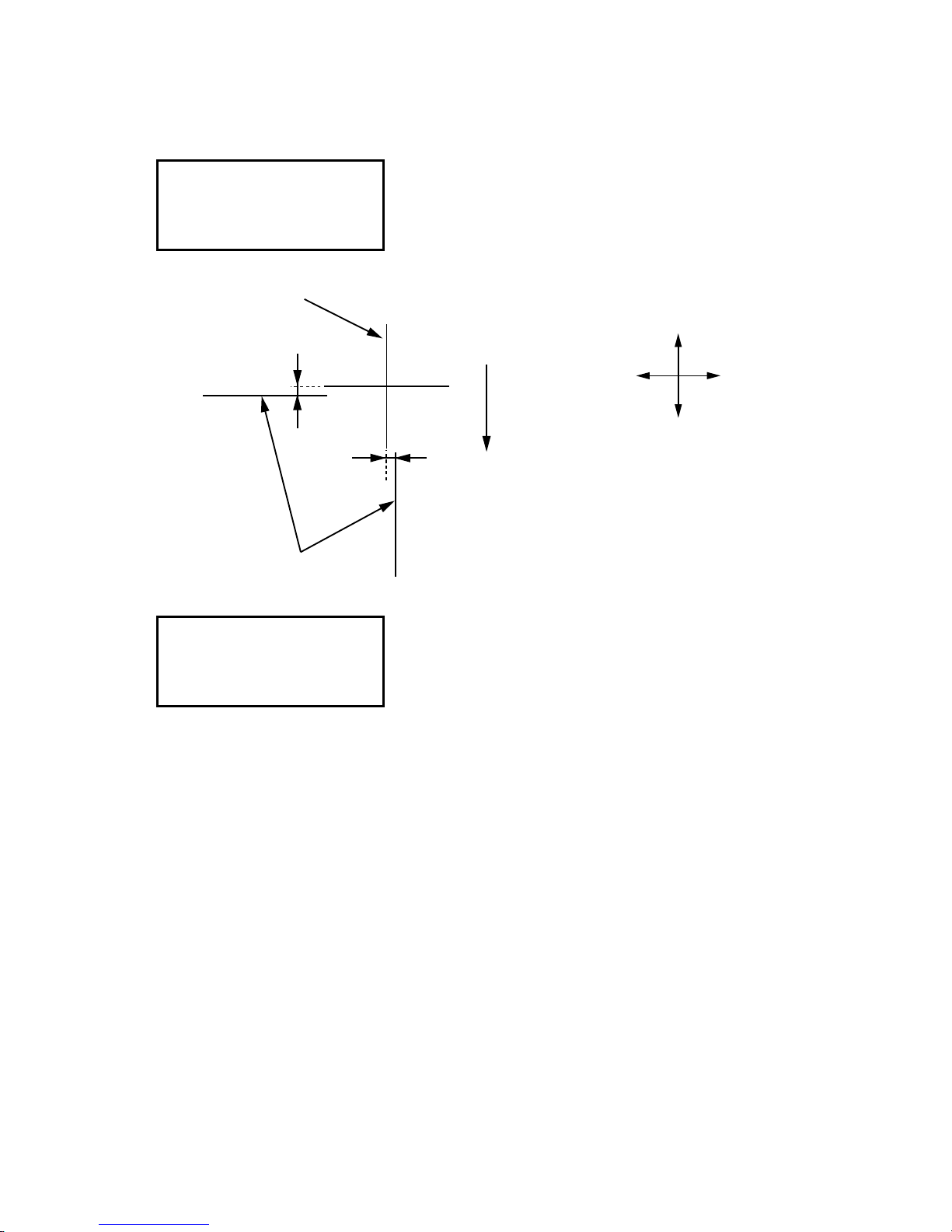
FC7000-UM-251-9370 7-30
7. ADJUSTMENT
(12) Use the ARROW keys to move the pens to an open area to plot the cross marks.
(13) Press the F3 key to plot the cross marks by pen 1 and pen 2 shown below.
When they have been plotted, the menu shown below is displayed.
PEN 1-2 OFFSET
ADJUST
TEST PATTERN>
PARAMETER SET>
(14) Measure the offset between the pen 1 cross mark and the pen 2 lines.
Media feed
direction
Lines plotted by pen 2
Cross mark
plotted by
pen 1
Y
X
+Y
-Y
+X
-X
(15) Press the F4 key to display the menu shown below.
PEN 1-2 OFFSET
ADJUST
X=+ 0.0 mm
Y=+ 0.0 mm
(16) Set the offset value(s). Press the UP ARROW key or DOWN ARROW key to change the number based
on the pen 1 cross mark.
Press the F3 key or F4 key to select the X or Y direction.
(17) Verify that the plotted pen 1 cross mark is located at the center of the plotted pen 2 lines.
(18) Repeat steps (13) to (16) if the plotted cross marks are incorrectly positioned. If the plotted cross marks
are in the correct positions, press the ENTER key to store the setting and complete the adjustment.
Page 97

FC7000-UM-251-9370 7-31
7. ADJUSTMENT
7.3.16 Adjusting the Servo Gain
This adjustment will set the servo gain for controlling the X/Y motor.
When you replace the main board of FC7000-75 to new type of main board (Main board for the FC7000MK2
series) this procedure is required.
The servo gain value is set to the default of firmware, except using the new type of main board (Main board
for the FC7000MK2 series) for the FC7000-75.
Note: You must readjust the servo gain when you performed the Nov-RAM Clear to the FC7000-75,
which is installed new main board.
How to adjsut the servo gain
(1) Mount a 0.9 mm diameter cutter pen in the pen holder.
(2) Load a sheet of paper in the plotter.
(3) Turn on the power while pressing the TEST and ENTER keys or after turning on the power, press the
TEST key and the ENTER key simultaneously within 2 seconds.
(4) Press the PAUSE key to display the menu shown below.
SENSOR TEST
KEY TEST
PEN FORCE
XY GAIN
(5) Press the F4 key to display the menu shown below.
GAIN
X=40 Y=70
(6) Input the values that are shown below.
Model X-Gain Y- Gain
FC7000-75 with new main board 30 32
Press the UP or DOWN ARROW key to change the X-Gain value.
Press the LEFT or RIGHT ARROW key to change the Y-Gain value.
(7) Press the ENTER key to store the setting and complete the adjustment.
Page 98

FC7000-UM-251-9370 7-32
7. ADJUSTMENT
7.4 Upgrading the System Firmware
To upgrade the system firmware you need to have the following files. In addition, you need to use a computer
and USB cable.
• FC7000V***.X :FC7000 firmware
Use the firmware version 1.8 or former to the FC7000.
Use the firmware version 3.0 or later to the FC7000Mk2.
Also use the firmware version 3.0 or later to new main board of the FC7000.
• SEND.EXE :Utility to transfer files using Windows
®
• OPS662 :USB Driver software for the FC7000
Preparation
Install the USB Driver software to your computer before upgrading the system firmware.
How to upgrade the system firmware
(1) Connect the computer and the plotter via the USB interface.
(2) Load a sheet of paper in the plotter.
(3) Turn on the power while pressing the LEFT ARROW and RIGHT ARROW keys.
Or
After turning on the power, press the LEFT ARROW key and the RIGHT ARROW key simultaneously
within 2 seconds.
(4) The plotter displays the menu shown below.
UPDATE ? No
(5) Select “Yes” using the UP ARROW or DOWN ARROW key.
UPDATE ? Yes
(6) Press the ENTER key to display the menu shown below.
PLEASE SEND PRG.
(7) Send firmware to the plotter from the computer.
Execute SEND.EXE.
Select the system firmware file from the SEND.EXE menu.
Output the system firmware file to the FC7000.
Page 99

FC7000-UM-251-9370 7-33
7. ADJUSTMENT
(8) The following menu is displayed while data is being received.
**KB RECEIVED
(9) The plotter will start the initialization routine when all the data has been received. The firmware version
is displayed during the initialization routine. Check the firmware version that you upgraded.
(10) Turn off the power.
Page 100

 Loading...