

Page 1

A-75/100/130/150
user manual
MANUAL NO. FC5100-UM-154
Page 2

Thank you for choosing an FC5100A Cutting Plotter.
The FC5100A is a high-performance grit-rolling cutting plotter that incorporates a 16-bit CPU and digital
servo drive system for highly precise cutting of color adhesive film at high speed.
For more information about Graphtec and Graphtec products, visit Graphtec’s corporate web sites at:
www.graphtecusa.com
www.graphteccorp.com (Other regions)
(USA, Canada, South America)
Page 3

Page 4

Table of Contents
Chapter 1: Special Precautions . . . . . . . . . . . . . . . . . . . . . . . . 12
Handling the Cutting Blades . . . . . . . . . . . . . . . . . . . . . . . . . . . . . . . . . . 12
Handling the Cutters . . . . . . . . . . . . . . . . . . . . . . . . . . . . . . . . . . . . . . . . . 12
Attaching a Cutter Pen . . . . . . . . . . . . . . . . . . . . . . . . . . . . . . . . . . . . . . . 13
After Turning on the Plotter . . . . . . . . . . . . . . . . . . . . . . . . . . . . . . . . . . . 15
Machine Caution Label . . . . . . . . . . . . . . . . . . . . . . . . . . . . . . . . . . . . . . 16
Notes on Working Environment . . . . . . . . . . . . . . . . . . . . . . . . . . . . . . . . 17
Notes on Use . . . . . . . . . . . . . . . . . . . . . . . . . . . . . . . . . . . . . . . . . . . . . . . 18
Daily Maintenance . . . . . . . . . . . . . . . . . . . . . . . . . . . . . . . . . . . . . . . . . . 19
Storing the Plotter . . . . . . . . . . . . . . . . . . . . . . . . . . . . . . . . . . . . . . . . . . . 19
Chapter 2: Out of the Box . . . . . . . . . . . . . . . . . . . . . . . . . . . . 20
Checking the Contents . . . . . . . . . . . . . . . . . . . . . . . . . . . . . . . . . . . . . . . 20
Accessories . . . . . . . . . . . . . . . . . . . . . . . . . . . . . . . . . . . . . . . . . . . . . . . . . . . . . . . . 20
Nomenclature . . . . . . . . . . . . . . . . . . . . . . . . . . . . . . . . . . . . . . . . . . . . . . 21
Installing the Accuload System . . . . . . . . . . . . . . . . . . . . . . . . . . . . . . . . 23
Connecting the Plotter . . . . . . . . . . . . . . . . . . . . . . . . . . . . . . . . . . . . . . . 25
Connecting to the Computer . . . . . . . . . . . . . . . . . . . . . . . . . . . . . . . . . . . . . . . . . . . 25
Connecting to the Power . . . . . . . . . . . . . . . . . . . . . . . . . . . . . . . . . . . . . . . . . . . . . . 26
Power to the Plotter . . . . . . . . . . . . . . . . . . . . . . . . . . . . . . . . . . . . . . . . . . . . . . . . . . 26
Chapter 3: Cutters and Holders . . . . . . . . . . . . . . . . . . . . . . . 28
Blade Application and Features . . . . . . . . . . . . . . . . . . . . . . . . . . . . . . . . 28
Cutter Pen Nomenclature . . . . . . . . . . . . . . . . . . . . . . . . . . . . . . . . . . . . . 29
PHP32-CB09N Cutter Pen . . . . . . . . . . . . . . . . . . . . . . . . . . . . . . . . . . . . . . . . . . . . 29
PHP32-CB15N Cutter Pen . . . . . . . . . . . . . . . . . . . . . . . . . . . . . . . . . . . . . . . . . . . . 29
PHP31-CB15 Cutter Pen . . . . . . . . . . . . . . . . . . . . . . . . . . . . . . . . . . . . . . . . . . . . . . 29
PHP32-CB09 Cutter Pen . . . . . . . . . . . . . . . . . . . . . . . . . . . . . . . . . . . . . . . . . . . . . . 29
PHP32-CB15 Cutter Pen . . . . . . . . . . . . . . . . . . . . . . . . . . . . . . . . . . . . . . . . . . . . . . 29
Replacing the Cutter Blade . . . . . . . . . . . . . . . . . . . . . . . . . . . . . . . . . . . . 29
Cutter Offset Value Settings . . . . . . . . . . . . . . . . . . . . . . . . . . . . . . . . . . . . . . . . . . . 30
Replacing Supersteel Blades . . . . . . . . . . . . . . . . . . . . . . . . . . . . . . . . . . . . . . . . . . . 30
Replacing Ceramic & Sapphire Blades . . . . . . . . . . . . . . . . . . . . . . . . . . . . . . . . . . . 31
Blade Length . . . . . . . . . . . . . . . . . . . . . . . . . . . . . . . . . . . . . . . . . . . . . . 32
Adjusting the Blade Length . . . . . . . . . . . . . . . . . . . . . . . . . . . . . . . . . . . . . . . . . . . 32
Obtaining the Correct Blade Length . . . . . . . . . . . . . . . . . . . . . . . . . . . . . . . . . . . . . 32
Page 5

Chapter 4: Preparing to Cut . . . . . . . . . . . . . . . . . . . . . . . . . . 34
Control Panel . . . . . . . . . . . . . . . . . . . . . . . . . . . . . . . . . . . . . . . . . . . . . . 34
Indicator Lamps . . . . . . . . . . . . . . . . . . . . . . . . . . . . . . . . . . . . . . . . . . . . . . . . . . . . 34
Function Keys . . . . . . . . . . . . . . . . . . . . . . . . . . . . . . . . . . . . . . . . . . . . . . . . . . . . . . 34
Position Keys . . . . . . . . . . . . . . . . . . . . . . . . . . . . . . . . . . . . . . . . . . . . . . . . . . . . . . 34
Menu Keys . . . . . . . . . . . . . . . . . . . . . . . . . . . . . . . . . . . . . . . . . . . . . . . . . . . . . . . . 35
Selecting a Function Menu . . . . . . . . . . . . . . . . . . . . . . . . . . . . . . . . . . . . 36
Initial Menu . . . . . . . . . . . . . . . . . . . . . . . . . . . . . . . . . . . . . . . . . . . . . . . 37
Setting the Multilanguage Display . . . . . . . . . . . . . . . . . . . . . . . . . . . . . . 37
Turn on the Plotter . . . . . . . . . . . . . . . . . . . . . . . . . . . . . . . . . . . . . . . . . . 38
Loading Media . . . . . . . . . . . . . . . . . . . . . . . . . . . . . . . . . . . . . . . . . . . . . 39
Sheet Media . . . . . . . . . . . . . . . . . . . . . . . . . . . . . . . . . . . . . . . . . . . . . . . . . . . . . . . . 39
Roll Media . . . . . . . . . . . . . . . . . . . . . . . . . . . . . . . . . . . . . . . . . . . . . . . . . . . . . . . . . 41
Select the Media Type . . . . . . . . . . . . . . . . . . . . . . . . . . . . . . . . . . . . . . . 46
ROLL–1 . . . . . . . . . . . . . . . . . . . . . . . . . . . . . . . . . . . . . . . . . . . . . . . . . . . . . . . . . . 46
ROLL–2 . . . . . . . . . . . . . . . . . . . . . . . . . . . . . . . . . . . . . . . . . . . . . . . . . . . . . . . . . . 46
SHEET . . . . . . . . . . . . . . . . . . . . . . . . . . . . . . . . . . . . . . . . . . . . . . . . . . . . . . . . . . . 47
CONTINUE . . . . . . . . . . . . . . . . . . . . . . . . . . . . . . . . . . . . . . . . . . . . . . . . . . . . . . . 47
Initializing Routine . . . . . . . . . . . . . . . . . . . . . . . . . . . . . . . . . . . . . . . . . . 48
ROLL-1 . . . . . . . . . . . . . . . . . . . . . . . . . . . . . . . . . . . . . . . . . . . . . . . . . . . . . . . . . . . 48
ROLL-2 . . . . . . . . . . . . . . . . . . . . . . . . . . . . . . . . . . . . . . . . . . . . . . . . . . . . . . . . . . . 49
SHEET . . . . . . . . . . . . . . . . . . . . . . . . . . . . . . . . . . . . . . . . . . . . . . . . . . . . . . . . . . . 49
CONTINUE . . . . . . . . . . . . . . . . . . . . . . . . . . . . . . . . . . . . . . . . . . . . . . . . . . . . . . . 49
Setting Conditions . . . . . . . . . . . . . . . . . . . . . . . . . . . . . . . . . . . . . . . . . . 50
Select the Tool from the Menu . . . . . . . . . . . . . . . . . . . . . . . . . . . . . . . . . . . . . . . . . 51
TANGENTIAL mode . . . . . . . . . . . . . . . . . . . . . . . . . . . . . . . . . . . . . . . . . . . . . . . . 52
Cutter Conditions . . . . . . . . . . . . . . . . . . . . . . . . . . . . . . . . . . . . . . . . . . . . . . . . . . . 52
To Change the Cutter Force . . . . . . . . . . . . . . . . . . . . . . . . . . . . . . . . . . . . . . . . . . 52
To Change the Cutter Speed . . . . . . . . . . . . . . . . . . . . . . . . . . . . . . . . . . . . . . . . . . 53
To Change the Cutter Quality. . . . . . . . . . . . . . . . . . . . . . . . . . . . . . . . . . . . . . . . . 53
To Change the Cutter Offset. . . . . . . . . . . . . . . . . . . . . . . . . . . . . . . . . . . . . . . . . . 54
Fine Adjustment . . . . . . . . . . . . . . . . . . . . . . . . . . . . . . . . . . . . . . . . . . . . . . . . . . . 54
Running Cutting Tests . . . . . . . . . . . . . . . . . . . . . . . . . . . . . . . . . . . . . . . . . . . . . . . . 54
Test 1 . . . . . . . . . . . . . . . . . . . . . . . . . . . . . . . . . . . . . . . . . . . . . . . . . . . . . . . . . . . . . 55
Test 2 . . . . . . . . . . . . . . . . . . . . . . . . . . . . . . . . . . . . . . . . . . . . . . . . . . . . . . . . . . . . . 56
Cutting Pro . . . . . . . . . . . . . . . . . . . . . . . . . . . . . . . . . . . . . . . . . . . . . . . . . . . . . . . . 56
Plotter Pen Conditions . . . . . . . . . . . . . . . . . . . . . . . . . . . . . . . . . . . . . . . . . . . . . . . . 57
Pen Reference Values . . . . . . . . . . . . . . . . . . . . . . . . . . . . . . . . . . . . . . . . . . . . . . . 57
To Change the Pen Force . . . . . . . . . . . . . . . . . . . . . . . . . . . . . . . . . . . . . . . . . . . . 58
To Change the Pen Speed . . . . . . . . . . . . . . . . . . . . . . . . . . . . . . . . . . . . . . . . . . . . 58
To Change the Pen Quality. . . . . . . . . . . . . . . . . . . . . . . . . . . . . . . . . . . . . . . . . . . 59
Pounce Conditions . . . . . . . . . . . . . . . . . . . . . . . . . . . . . . . . . . . . . . . . . . . . . . . . . . 59
Page 6

To Change the Pounce Force . . . . . . . . . . . . . . . . . . . . . . . . . . . . . . . . . . . . . . . . . 59
To Change the Pounce Speed . . . . . . . . . . . . . . . . . . . . . . . . . . . . . . . . . . . . . . . . . 60
To Change the Pounce Quality . . . . . . . . . . . . . . . . . . . . . . . . . . . . . . . . . . . . . . . . 60
To Change the Pounce Offset . . . . . . . . . . . . . . . . . . . . . . . . . . . . . . . . . . . . . . . . . 61
Changing Feed Speed . . . . . . . . . . . . . . . . . . . . . . . . . . . . . . . . . . . . . . . . 61
Withdrawal of the Pen Carriage . . . . . . . . . . . . . . . . . . . . . . . . . . . . . . . . 63
Returning the Pen Carriage to Origin . . . . . . . . . . . . . . . . . . . . . . . . . . . . 63
Chapter 5: Advanced Functions and Settings . . . . . . . . . . . . 64
Control Panel Quick Keys . . . . . . . . . . . . . . . . . . . . . . . . . . . . . . . . . . . . 64
Menu Controls . . . . . . . . . . . . . . . . . . . . . . . . . . . . . . . . . . . . . . . . . . . . . 64
ORIGIN - Setting the Cutting Origin . . . . . . . . . . . . . . . . . . . . . . . . . . . . 65
Origin Point with ROTATE function . . . . . . . . . . . . . . . . . . . . . . . . . . . . . . . . . . . . 66
COPY - Copying the Data in Plotter Buffer Memory . . . . . . . . . . . . . . . 66
Copying Sequence . . . . . . . . . . . . . . . . . . . . . . . . . . . . . . . . . . . . . . . . . . . . . . . . . . . 68
PEN UP/DOWN - Raising/Lowering the Pen . . . . . . . . . . . . . . . . . . . . . 69
BUFFER CLEAR - Clearing the Buffer . . . . . . . . . . . . . . . . . . . . . . . . . 69
FEED - Advancing the Media . . . . . . . . . . . . . . . . . . . . . . . . . . . . . . . . . 70
ORIGIN - Setting the Origin in HP-GL Mode . . . . . . . . . . . . . . . . . . . . 71
AREA - Setting the Cutting Area . . . . . . . . . . . . . . . . . . . . . . . . . . . . . . . 72
EXPAND - Expanding the Cut Area . . . . . . . . . . . . . . . . . . . . . . . . . . . . 75
PAGE LENGTH - Setting the Length of the Page with Roll Media . . . . 77
ROTATE - Rotating the Coordinate Axes . . . . . . . . . . . . . . . . . . . . . . . . 78
MIRROR – Reversing the Image . . . . . . . . . . . . . . . . . . . . . . . . . . . . . . . 79
SCALE - Enlarging and Reducing an Image Size . . . . . . . . . . . . . . . . . . 80
DATA SORTING - Sorting the Cut Data . . . . . . . . . . . . . . . . . . . . . . . . 81
AXIS ALIGNMENT - Axis Alignment Parameter Setting . . . . . . . . . . . 83
Selecting the Axis Alignment Method . . . . . . . . . . . . . . . . . . . . . . . . . . . . . . . . . . . 84
Two-Point Method . . . . . . . . . . . . . . . . . . . . . . . . . . . . . . . . . . . . . . . . . . . . . . . . . 84
Three-Point Method . . . . . . . . . . . . . . . . . . . . . . . . . . . . . . . . . . . . . . . . . . . . . . . . 84
Four-Point Method . . . . . . . . . . . . . . . . . . . . . . . . . . . . . . . . . . . . . . . . . . . . . . . . . 84
Axis Alignment Adjustment . . . . . . . . . . . . . . . . . . . . . . . . . . . . . . . . . . . . . . . . . . . 86
AUTO REG. MARK - Auto Registration Mark Sensor . . . . . . . . . . . . . . 91
AUTO REG. MARK . . . . . . . . . . . . . . . . . . . . . . . . . . . . . . . . . . . . . . . . . . . . . . . . . 92
The Registration Mark Pattern . . . . . . . . . . . . . . . . . . . . . . . . . . . . . . . . . . . . . . . . 92
The Registration Mark Location. . . . . . . . . . . . . . . . . . . . . . . . . . . . . . . . . . . . . . . 93
The Registration Mark Reading Area. . . . . . . . . . . . . . . . . . . . . . . . . . . . . . . . . . . 94
The Position of the Origin Point . . . . . . . . . . . . . . . . . . . . . . . . . . . . . . . . . . . . . . . 95
Media For Which Registration Marks Cannot Be Detected . . . . . . . . . . . . . . . . . . 96
If Registration Mark Can Not Be Automatically Recognized . . . . . . . . . . . . . . . . 96
Page 7

Specifying the Registration Mark Mode. . . . . . . . . . . . . . . . . . . . . . . . . . . . . . . . . 96
Axis alignment method. . . . . . . . . . . . . . . . . . . . . . . . . . . . . . . . . . . . . . . . . . . . . . 96
SCANNING METHODS . . . . . . . . . . . . . . . . . . . . . . . . . . . . . . . . . . . . . . . . . . . . 97
Selecting the Axis Alignment Method . . . . . . . . . . . . . . . . . . . . . . . . . . . . . . . . . . . 98
TWO-POINTS METHOD . . . . . . . . . . . . . . . . . . . . . . . . . . . . . . . . . . . . . . . . . . . 98
THREE-POINTS METHOD . . . . . . . . . . . . . . . . . . . . . . . . . . . . . . . . . . . . . . . . . 99
FOUR-POINTS METHOD . . . . . . . . . . . . . . . . . . . . . . . . . . . . . . . . . . . . . . . . . 101
Setting the Registration Mark Reading Area . . . . . . . . . . . . . . . . . . . . . . . . . . . . . 103
Selecting the Registration MARK TYPE . . . . . . . . . . . . . . . . . . . . . . . . . . . . . . . . 105
Specifying the Registration MARK SIZE . . . . . . . . . . . . . . . . . . . . . . . . . . . . . . . . 106
Setting the DISTANCE ADJUSTMENT . . . . . . . . . . . . . . . . . . . . . . . . . . . . . . . . 108
Setting of AXIS ORIGIN OFFSET . . . . . . . . . . . . . . . . . . . . . . . . . . . . . . . . . . . . 109
Setting of PAPER-WEIGHT Function . . . . . . . . . . . . . . . . . . . . . . . . . . . . . . . . . . 111
Setting the SENSOR OFFSET ADJustment . . . . . . . . . . . . . . . . . . . . . . . . . . . . . . 112
Selecting METHOD 1 . . . . . . . . . . . . . . . . . . . . . . . . . . . . . . . . . . . . . . . . . . . . . 113
Selecting METHOD 2 . . . . . . . . . . . . . . . . . . . . . . . . . . . . . . . . . . . . . . . . . . . . . 114
Using the AUTO REG. MARK Sensing Function . . . . . . . . . . . . . . . . . . . . . . . . . 116
AUTO PRE-FEED - Advancing the Media Automatically . . . . . . . . . . 119
TANGENTIAL EMULATION - Cutting Thick & Thin Material . . . . . 121
Selecting Tangential Emulation Mode . . . . . . . . . . . . . . . . . . . . . . . . . . . . . . . . . . 121
Enabling Tangential Emulation . . . . . . . . . . . . . . . . . . . . . . . . . . . . . . . . . . . . . . . . 122
Setting Overcut . . . . . . . . . . . . . . . . . . . . . . . . . . . . . . . . . . . . . . . . . . . . . . . . . . . . 123
SPEED - Setting the Pen-Up Speed . . . . . . . . . . . . . . . . . . . . . . . . . . . . 124
OFFSET ANGLE - Adjusting the Blade Offset Angle . . . . . . . . . . . . . 125
OFFSET FORCE - Setting the Offset Cut Pressure . . . . . . . . . . . . . . . . 126
STEP PASS - Setting the Step Pass . . . . . . . . . . . . . . . . . . . . . . . . . . . . 127
INITIAL DOWN FORCE- Adjusting the Initial Media Cut Force . . . . 128
DISTANCE ADJUST - Adjusting the Length of Line Segments . . . . . 129
Setting Distance Adjust Parameter . . . . . . . . . . . . . . . . . . . . . . . . . . . . . . . . . . . . . 130
RS-232C Serial Interface . . . . . . . . . . . . . . . . . . . . . . . . . . . . . . . . . . . . 131
Pin Assignment of the Serial Connector . . . . . . . . . . . . . . . . . . . . . . . . . . . . . . . . . 131
Cable Connection . . . . . . . . . . . . . . . . . . . . . . . . . . . . . . . . . . . . . . . . . . . . . . . . . . 132
Chapter 6: Background Settings . . . . . . . . . . . . . . . . . . . . . . 134
Background Settings for GP-GL . . . . . . . . . . . . . . . . . . . . . . . . . . . . . . 136
LANGUAGE SELECTION . . . . . . . . . . . . . . . . . . . . . . . . . . . . . . . . . . . . . . . . . . 136
“:” “;” Command Control (“:” “;” COMMAND) . . . . . . . . . . . . . . . . . . . . . . . . . . 136
Pen UP/DOWN for the “W” Command . . . . . . . . . . . . . . . . . . . . . . . . . . . . . . . . . 137
Condition Priority . . . . . . . . . . . . . . . . . . . . . . . . . . . . . . . . . . . . . . . . . . . . . . . . . . 137
Pen Select . . . . . . . . . . . . . . . . . . . . . . . . . . . . . . . . . . . . . . . . . . . . . . . . . . . . . . . . 138
Initial Blade Control Position (INITIAL BLADE CONTROL) . . . . . . . . . . . . . . . 139
Length Unit . . . . . . . . . . . . . . . . . . . . . . . . . . . . . . . . . . . . . . . . . . . . . . . . . . . . . . . 139
Page 8

UP Movement Control (PEN UP MOVE) . . . . . . . . . . . . . . . . . . . . . . . . . . . . . . . 140
Media Sensor Control . . . . . . . . . . . . . . . . . . . . . . . . . . . . . . . . . . . . . . . . . . . . . . . 141
Pinch Roller Sensor Control . . . . . . . . . . . . . . . . . . . . . . . . . . . . . . . . . . . . . . . . . . 141
Background Settings for HP-GL . . . . . . . . . . . . . . . . . . . . . . . . . . . . . . 142
LANGUAGE SELECTION . . . . . . . . . . . . . . . . . . . . . . . . . . . . . . . . . . . . . . . . . . 142
Model No. Response (MODEL EMULATED) . . . . . . . . . . . . . . . . . . . . . . . . . . . 143
Condition Priority . . . . . . . . . . . . . . . . . . . . . . . . . . . . . . . . . . . . . . . . . . . . . . . . . . 143
Initial Blade Control Position (INITIAL BLADE CONTROL) . . . . . . . . . . . . . . . 144
Length Unit . . . . . . . . . . . . . . . . . . . . . . . . . . . . . . . . . . . . . . . . . . . . . . . . . . . . . . . 145
UP Movement Control (PEN UP MOVE) . . . . . . . . . . . . . . . . . . . . . . . . . . . . . . . 145
Media Sensor Control . . . . . . . . . . . . . . . . . . . . . . . . . . . . . . . . . . . . . . . . . . . . . . . 146
Pinch Roller Sensor Control . . . . . . . . . . . . . . . . . . . . . . . . . . . . . . . . . . . . . . . . . . 147
Circle Resolution . . . . . . . . . . . . . . . . . . . . . . . . . . . . . . . . . . . . . . . . . . . . . . . . . . . 147
Chapter 7: Test Modes and Troubleshooting . . . . . . . . . . . . 150
CONDITION LIST - Listing the Cutting Conditions . . . . . . . . . . . . . . 150
Sample printout of the CONDITION function . . . . . . . . . . . . . . . . . . . . . . . . . . . . 151
DATA DUMP - Using the Character Dump Mode . . . . . . . . . . . . . . . . 152
SELF TEST - Running the Self Test . . . . . . . . . . . . . . . . . . . . . . . . . . . 153
Troubleshooting . . . . . . . . . . . . . . . . . . . . . . . . . . . . . . . . . . . . . . . . . . . 155
Error Messages . . . . . . . . . . . . . . . . . . . . . . . . . . . . . . . . . . . . . . . . . . . . 162
Error Messages in HP-GL Command Mode . . . . . . . . . . . . . . . . . . . . . . . . . . . . . . 163
Chapter 8: Setting the Interface Functions . . . . . . . . . . . . . 166
Setting the Parallel Interface . . . . . . . . . . . . . . . . . . . . . . . . . . . . . . . . . 166
Setting the USB Interface . . . . . . . . . . . . . . . . . . . . . . . . . . . . . . . . . . . . 166
Setting the Serial Interface . . . . . . . . . . . . . . . . . . . . . . . . . . . . . . . . . . . 167
Factory Preset Interface Settings . . . . . . . . . . . . . . . . . . . . . . . . . . . . . . . . . . . . . . . 167
INTERFACE - Setting the Interface Functions . . . . . . . . . . . . . . . . . . . 167
How to access the INTERFACE menu before loading the media . . . . . . . . . . . . . 167
How to access the INTERFACE menu after loading the media . . . . . . . . . . . . . . . 168
STEP SIZE - Setting the Programmable Resolution . . . . . . . . . . . . . . . 168
RS-232C – Setting the Data Transmitting Conditions . . . . . . . . . . . . . . 170
COMMAND - Selecting the Command Mode . . . . . . . . . . . . . . . . . . . . 171
Centronics-Compatible Parallel Interface . . . . . . . . . . . . . . . . . . . . . . . 171
Specifications . . . . . . . . . . . . . . . . . . . . . . . . . . . . . . . . . . . . . . . . . . . . . . . . . . . . . 172
Electrical Characteristics . . . . . . . . . . . . . . . . . . . . . . . . . . . . . . . . . . . . . . . . . . . . . 172
Input/Output Circuitry . . . . . . . . . . . . . . . . . . . . . . . . . . . . . . . . . . . . . . . . . . . . . . . 172
Input/Output Timing Chart . . . . . . . . . . . . . . . . . . . . . . . . . . . . . . . . . . . . . . . . . . . 173
Pin Assignment of the Parallel Connector . . . . . . . . . . . . . . . . . . . . . . . . . . . . . . . 173
Page 9

RS-232C Serial Interface . . . . . . . . . . . . . . . . . . . . . . . . . . . . . . . . . . . . 174
Pin Assignment of the Serial Connector . . . . . . . . . . . . . . . . . . . . . . . . . . . . . . . . . 174
Cable Connection . . . . . . . . . . . . . . . . . . . . . . . . . . . . . . . . . . . . . . . . . . . . . . . . . . 175
Chapter 9: Specifications . . . . . . . . . . . . . . . . . . . . . . . . . . . . 176
Main Specifications: FC5100A-75 . . . . . . . . . . . . . . . . . . . . . . . . . . . . 176
Main Specifications: FC5100A-100 . . . . . . . . . . . . . . . . . . . . . . . . . . . 177
Main Specifications: FC5100A-130 . . . . . . . . . . . . . . . . . . . . . . . . . . . 178
Main Specifications: FC5100A-150 . . . . . . . . . . . . . . . . . . . . . . . . . . . 179
Options . . . . . . . . . . . . . . . . . . . . . . . . . . . . . . . . . . . . . . . . . . . . . . . . . . 180
External Dimensions . . . . . . . . . . . . . . . . . . . . . . . . . . . . . . . . . . . . . . . 180
FC5100A-75 without Stand . . . . . . . . . . . . . . . . . . . . . . . . . . . . . . . . . . . . . . . . . . 180
FC5100A-100 without Stand . . . . . . . . . . . . . . . . . . . . . . . . . . . . . . . . . . . . . . . . . 181
FC5100A-130 without Stand . . . . . . . . . . . . . . . . . . . . . . . . . . . . . . . . . . . . . . . . . 181
FC5100A-150 without Stand . . . . . . . . . . . . . . . . . . . . . . . . . . . . . . . . . . . . . . . . . 182
FC5100A-75 with Stand and Basket Option . . . . . . . . . . . . . . . . . . . . . . . . . . . . . . 182
FC5100A-100 with Standard Stand and Basket Option . . . . . . . . . . . . . . . . . . . . . 183
FC5100A-130 with Standard Stand and Basket Option . . . . . . . . . . . . . . . . . . . . . 183
FC5100A-150 with Standard Stand and Basket Option . . . . . . . . . . . . . . . . . . . . . 183
Chapter 10: Options . . . . . . . . . . . . . . . . . . . . . . . . . . . . . . . . 184
FC5100A Pounce Tool Manual . . . . . . . . . . . . . . . . . . . . . . . . . . . . . . . 184
Inserting the Pounce Tool . . . . . . . . . . . . . . . . . . . . . . . . . . . . . . . . . . . . . . . . . . . . 184
Select Pounce Tool from the Menu . . . . . . . . . . . . . . . . . . . . . . . . . . . . . . . . . . . . . 185
Pounce Conditions . . . . . . . . . . . . . . . . . . . . . . . . . . . . . . . . . . . . . . . . . . . . . . . . . 185
To Change the Pounce Force . . . . . . . . . . . . . . . . . . . . . . . . . . . . . . . . . . . . . . . . 185
To Change the Pounce Speed . . . . . . . . . . . . . . . . . . . . . . . . . . . . . . . . . . . . . . . . 185
To Change the Pounce Quality . . . . . . . . . . . . . . . . . . . . . . . . . . . . . . . . . . . . . . . 186
To Change the Pounce Offset . . . . . . . . . . . . . . . . . . . . . . . . . . . . . . . . . . . . . . . . 186
FC5100A Stand Manual . . . . . . . . . . . . . . . . . . . . . . . . . . . . . . . . . . . . . 187
Contents . . . . . . . . . . . . . . . . . . . . . . . . . . . . . . . . . . . . . . . . . . . . . . . . . . . . . . . . . . 187
Stand Assembly . . . . . . . . . . . . . . . . . . . . . . . . . . . . . . . . . . . . . . . . . . . . . . . . . . . . 188
Assembly Area . . . . . . . . . . . . . . . . . . . . . . . . . . . . . . . . . . . . . . . . . . . . . . . . . . . 188
FC5100A Basket Manual . . . . . . . . . . . . . . . . . . . . . . . . . . . . . . . . . . . . 190
Contents . . . . . . . . . . . . . . . . . . . . . . . . . . . . . . . . . . . . . . . . . . . . . . . . . . . . . . . . . . 190
Basket Assembly . . . . . . . . . . . . . . . . . . . . . . . . . . . . . . . . . . . . . . . . . . . . . . . . . . . 190
Assembly Area . . . . . . . . . . . . . . . . . . . . . . . . . . . . . . . . . . . . . . . . . . . . . . . . . . . 190
FC5100A Media Roll Holder Manual . . . . . . . . . . . . . . . . . . . . . . . . . . 194
Contents . . . . . . . . . . . . . . . . . . . . . . . . . . . . . . . . . . . . . . . . . . . . . . . . . . . . . . . . . . 194
Media Roll Holder Assembly . . . . . . . . . . . . . . . . . . . . . . . . . . . . . . . . . . . . . . . . . 194
Assembly Area . . . . . . . . . . . . . . . . . . . . . . . . . . . . . . . . . . . . . . . . . . . . . . . . . . . 194
Page 10

FC5100A Loupe (PHP-61) Loupe . . . . . . . . . . . . . . . . . . . . . . . . . . . . . 197
Attaching the Loupe . . . . . . . . . . . . . . . . . . . . . . . . . . . . . . . . . . . . . . . . . . . . . . . . 197
Using the Loupe . . . . . . . . . . . . . . . . . . . . . . . . . . . . . . . . . . . . . . . . . . . . . . . . . . . 198
Chapter 11: Appendix . . . . . . . . . . . . . . . . . . . . . . . . . . . . . . 200
Page 11

Page 12

12
Chapter 1: Special Precautions
This section covers special precautions you should take when operating or storing your plotter.
NOTE: Information to simplify or correctly complete a task.
CAUTION: Will cause damage to the unit.
WARNING: Will cause injury to the Operator!
Handling the Cutting Blades
WARNING: Sharp cutter blades are used with this plotter. Handle the cutter blades
and holders with care to prevent bodily injury.
• Cutter blades are very sharp. While
handling a cutter blade or cutter pen,
be careful to avoid cutting your fingers
or other parts of your body.
Sharp
• Promptly return used blades to the cutter case provided. When the case is
completely filled, discard the used
blades together with the case.
Handling the Cutters
• The tip consists of a sharp blade. Be sure not to extend it too far.
• Instructions on replacing the blade
or adjusting the blade length are
provided in Cutters and Holders.
Special Precautions: Handling the Cutting Blades
Sharp Blade
Page 13

Attaching a Cutter Pen
WARNING: To avoid bodily injury, do not touch the pen tip after the plotter is turned
on.
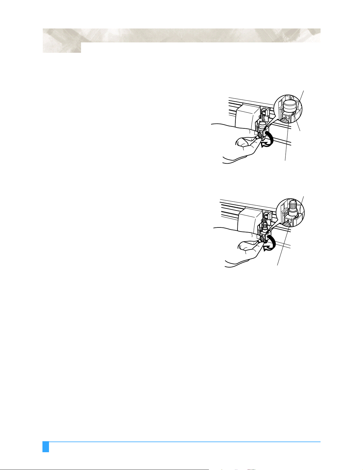
Follow the procedure below to attach a cutter pen to the pen carriage.
1 Make sure that the pen holder
screw is loose.
13
2 While positioning the pen
holder upward, push the cutter
pen all the way into the holder
until its rim contacts the pen
stopper.
3 Once the pen has been prop-
erly mounted, tighten the
screw.
Flange
Pen Holder
Flange
Bracket to hold pen
Special Precautions: Attaching a Cutter Pen
Page 14
14
CAUTION: The pen has two flanges
and must be fully seated
(the pen holder is engaged
on the second flange)
before tightening the
screw.
CAUTION: The cutter must be prop-
erly seated (the pen holder
is engaged on the flange)
before tightening the
screw.
Upper groove
Flange
Bracket to hold pen
Flange
Bracket to hold pen
Special Precautions: Attaching a Cutter Pen
Page 15
After Turning on the Plotter
During the course of turning on the plotter, be sure to observe the following pre-
cautions:
• The pen carriage and loaded media may suddenly move during the cutting operation, immediately afterward and when setting the plotter’s functions.
• Keep hands, hair, clothing and other objects out of the vicinity of the pen carriage, grit rollers and loaded media.
• To prevent operator injury and poor cutting results, be careful not to allow hands,
hair, clothing or other foreign objects to become entangled with the pen carriage
or loaded media while the plotter is operating.
15
Special Precautions: After Turning on the Plotter
Page 16

16
Machine Caution Label
The machine’s Caution Label is located on the top cover.
Special Precautions: Machine Caution Label
Page 17
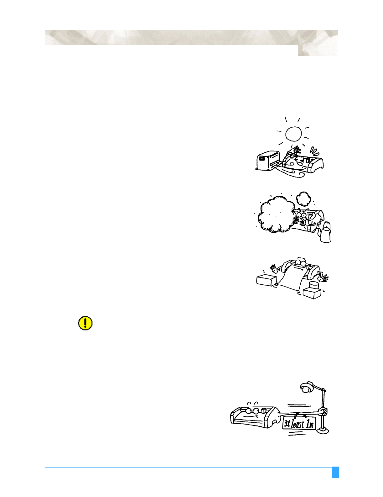
Notes on Working Environment
Be sure to observe the following regarding the working environment of your plot-
ter:
• Avoid use or storage of the plotter in locations
subject to direct sunlight or the direct draft
from air-conditioning.
• Avoid locations which are extremely dusty.
17
• Prior to cutting, ensure that no obstacles are
placed in the vicinity of the pen carriage or
loaded media.
CAUTION: Impeded movement of the pen carriage or loaded media may prevent accurate
cutting, or may trigger the position alarm to reset the system or system overload. An overloaded system triggers the product’s circuit protection. Should the
system overload, causing the power to shut down, turn off the power switch
and unplug the power cord. Wait 5 to 10 minutes then reconnect the power
cord and turn on the system. For more information, see Test Modes and Trou-
bleshooting.
To prevent malfunctions of the plotter’s sensors, position the plotter at
least one meter (3 feet) away from fluorescent lamps, electric lamps and
any other source of indoor illumination.
Special Precautions: Notes on Working Environment
Page 18

18
Notes on Use
Be sure to observe the following on the use of your plotter:
CAUTION: Make sure your computer and power sources are adequately grounded (the
RS-232 interface cable should meet the CCITT V24, EIA RS-232 standards.
Graphtec’s RS-232 serial interface cable conforms to the EIA standard). Inadequate grounding may result in severe damage to your plotter or computer and
constitute misuse of the plotter.
• Never lubricate the plotter mechanisms, this
will result in plotter malfunction.
• To avoid scratching the cutting mat, ensure
that the cutter pen blade is not excessively
extended.
• Do not touch the moving parts of the plotter
while it is operating.
• When manually moving the pen carriage to
load the media, be sure to move the carriage
slowly.
CAUTION: Do not unplug or plug in the USB connector when the plotter is working or you
will lose data when the computer restores the USB directory.
Special Precautions: Notes on Use
Page 19

Daily Maintenance
During the course of daily plotter operation, be sure to observe the following
precautions:
• Never lubricate the mechanisms of the plotter.
• Clean the plotter’s casing using a dry cloth that has been moistened in a neutral
detergent diluted with water. Never use thinner, benzene, alcohol, or similar
solvents to clean the casings; they will damage the casing’s finish.
• Clean the cutting mat using a dry cloth. In case of stubborn stains, use a cloth
that has been moistened in alcohol or in a neutral detergent diluted with water.
• Clean the plotter’s paper sensors using a cloth moistened in a neutral detergent
diluted with water. Never use thinner, benzene, alcohol, or similar solvents to
clean the sensors; cleaners such as these will damage the sensors.
Storing the Plotter
19
When your plotter is not in use, be sure to observe the following points:
• Remove the pen attached to the penholder
• Cover the plotter with a cloth to protect it from dust and dirt
• Do not store the plotter in direct sunlight or in high temperatures
Special Precautions: Daily Maintenance
Page 20

20
Chapter 2: Out of the Box
This chapter describes plotter nomenclature and how to install your plotter.
Checking the Contents
After unpacking your plotter, check that all of the standard accessories shown
below are present. If any accessory is missing, contact your sales representative
or the nearest Graphtec dealer.
Accessories The Stand Kit is an option for the FC5100A-75 and is standard for the FC5100A-
100, FC5100A-130 and FC5100A-150 cutters.
Power cord. The configuration pictured
may differ from the actual cord supplied.
Cutter Pen Set. Cutter holder PHP32CB09N with two CB09UA cutter
blades.
RS-232 cable with adapter (US market only).
Black water-based fiber-tip pen
(KF552-BK-P).
Out of the Box: Checking the Contents
Page 21

User’s manual
Accuload™ System components.
21
Nomenclature
1 AC Line Inlet: Inlet where the power cord is connected.
2 Control Panel: Used to access various plotter functions.
3 Cutting Channel: A channel running along the cutting mat area. Used to
reduce pouncing tool wear.
4 Cutting Mat: A black strip placed under the cutting area. Used to reduce cut-
ting blade wear.
5 Grit Rollers: Metallic rollers which have a file-like surface.
6 Media Set Lever: Used to raise or lower the push rollers during loading or
unloading media.
7 Accuload™: Used to carry rolled media and ensure its proper rotation.
8 Paper Sensors: The front sensor is used to sense the leading edge of the
media. The rear sensor is used to sense the trailing edge of the media.
9 Parallel Interface Connector: Used to connect the plotter to the computer
with a Centronics-compatible parallel interface cable.
10 Pen Carriage: Moves the pen across the media during cutting or plotting.
11 Pen Holder: Holds the pen onto the pen carriage.
12 Power Switch: Used to turn the plotter on and off.
13 Pinch Rollers: Black rubber rollers that push the media against the grit roll-
ers.
Out of the Box: Nomenclature
Page 22

22
14 Roller Location Guide: Yellow markings on the rail and rear side of the top
cover that show the position of each grit roller. Use these guides as an aid in
locating the push rollers and in locating the media roll on the stock roller.
15 Serial Interface Connector: Used to connect the plotter to the computer with
a RS-232 serial interface cable.
16 Stock Rollers: Area of the media stocker where the media is mounted.
17 USB Connector: Used to connect the plotter to the computer with a USB inter-
face cable.
18 Stand: Used to make the plotter more portable and free-up counter space.
12
13
10
11
13
14
4
3
5
2
8
16
18
1
7
7
14
6
Out of the Box: Nomenclature
9
17
15
Page 23

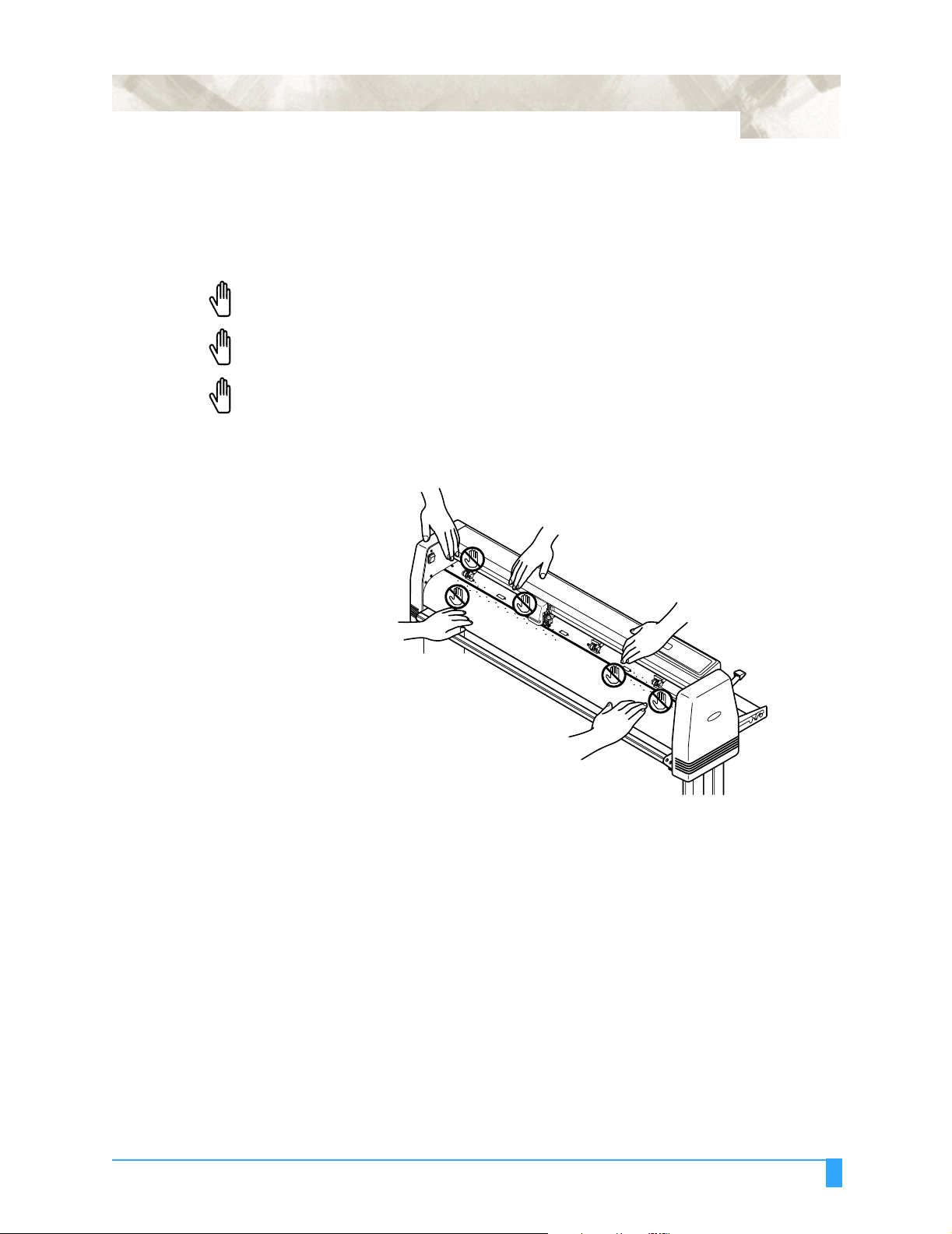
Installing the Accuload System
The Accuload™ system consists of two media brackets, two stock rollers and
one media alignment bar.
Installation procedure:
1 Place the right media bracket against the inside surface of the plotter’s side
box (right).
Front
23
M4 Screw
Media Bracket Right
2 Insert an M4 screw in the second hole from the front side of the plotter.
NOTE: Do not over tighten. The bracket should rotate easily.
NOTE: When attaching the bracket onto the cutter, use the foam shipping cover to pro-
tect the cutter.
CAUTION: Do not lay the cutter on its back side, this may damage the Media Set Lever.
3 Insert an M4 screw in the third hole from the front side of the plotter.
4 Secure the first screw.
5 Secure the second screw.
6 Repeat steps 1-5 with the left Media Bracket.
7 Place the media alignment bar in between the tabs of the media brackets that
protrude from the front side of the plotter.
Media Bracket Left
Out of the Box: Installing the Accuload System
Page 24

24
8 Secure the media alignment bar to the tabs at both ends with M4 screws.
Rear
M4 Screw
Media Alignment Bar
Groove
M4 Screw
9 Install the stock rollers into the holes on the rear side of the media brackets.
Front
Stock Roller
NOTE: Be sure to tighten all the screws to ensure accurate media loading. The Accu-
load™ system may not function properly if even one of the screws is loose.
NOTE: Be sure to place the plotter on an acceptable work surface. Refer to dimen-
sions below:
FC5100A-75: 45 inches (114cm) wide by 19 inches (48cm) deep.
FC5100A-100: 57 inches (144cm) wide by 19 inches (48cm) deep.
FC5100A-130: 67 inches (170cm) wide by 19 inches (48cm) deep.
FC5100A-150: 73 inches (186cm) wide by 19 inches (48cm) deep.
Out of the Box: Installing the Accuload System
Page 25

Connecting the Plotter
25
Connecting to the Computer
The FC5100A Plotter is equipped with an RS-232 Serial Interface Cable in the
accessory kit.
1 Connect the 25-pin connector to the
RS232-C connector on the plotter and
tighten the screws. If you are using a
Centronics-compatible parallel interface
cable, connect the 36-pin connector to
the Parallel connector on the plotter and
lock the levers.If you are using a USB
connentor, connect the connector to the
USB connector on the plotter.
2 Connect the 9-pin connector to the
RS-232C
connector on the computer COM port
and tighten the screws. If your computer
has a 25-pin connector port, use the 9pin to 25-pin adapter that is supplied in
the accessory kit.
Parallel
USB
Out of the Box: Connecting the Plotter
Page 26

26
Connecting to the Power
Power to the Plotter
The FC5100A Plotter is equipped with a Power Cord in the accessory kit.
1 Connect the provided power cord to the AC inlet of the plotter.
2 Connect the other end of the power cord to an electrical socket of the rated supply voltage.
To turn on the plotter, perform the following steps:
1 Make sure that the plotter is turned off (the “O” side of the
POWER switch is depressed).
2 Connect the plotter to a computer and then configure your
software application to the desired interface conditions, (if the
RS-232-C serial interface is used), command mode and programmable resolution.
3 Connect one end of the provided power cord to the plotter’s AC line inlet then
connect the other end of the power cord to an electrical socket of the rated
supply voltage. The plotter’s power supply accepts multi-voltage (100VAC to
240VAC) without changing switches.
4 Turn on the computer.
5 Turn on the plotter by depressing the “l” side of the POWER
switch.
Out of the Box: Connecting the Plotter
Page 27

27
Out of the Box: Connecting the Plotter
Page 28
28
Chapter 3: Cutters and Holders
This chapter describes the different cutters and their uses.
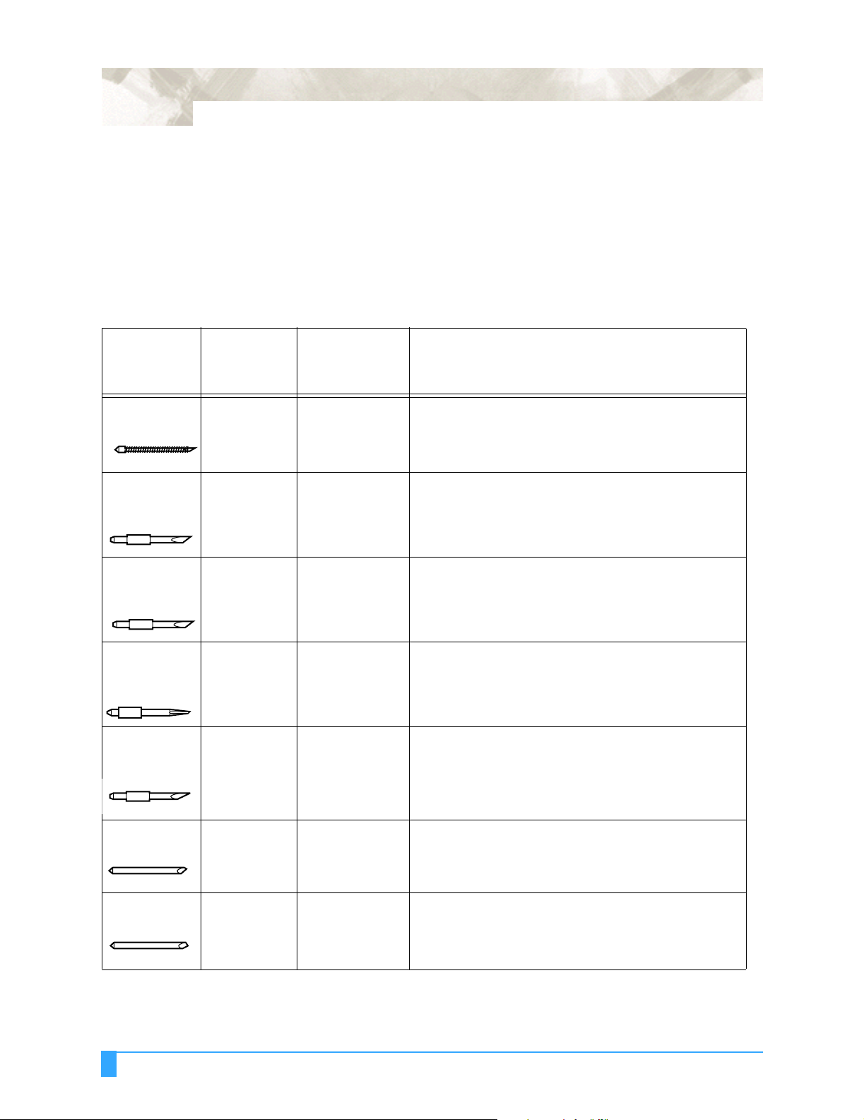
Blade Application and Features
Blade part
no. and
type
CB09UA
(supersteel)
CB15U
(supersteel)
CB15UA
(supersteel)
CB15UB
(supersteel)
CB15U-K30
(supersteel)
Diameter
and blade
offset value
0.9 mm
0.45
1.5 mm
0.75
1.5 mm
0.75
1.5 mm
0.75
1.5 mm
0.75
Plunger part
no. Applications and features
PHP32-CB09N
or
PHP32-CB09
PHP32-CB15N
or
PHP32-CB15
PHP32-CB15N For cutting high intensity reflective media.
PHP32-CB15N For cutting small characters on mono-vinyl chloride
PHP32-CB15N
or
PHP32-CB15
Standard blade for cutting color adhesive media. Suitable
for cutting media up to 0.25 mm thick. Maximum cutting
distance of approximately 4000 m.
For cutting media which is too thick for the CB09UA
blade to handle. Suitable for cutting media from 0.25 mm
to 0.5 mm thick.
media. Suitable for cutting small size characters that are
less than 10mm.
For cutting sandblast rubber. The sharply angled point
provides a longer cutting edge. Suitable for cutting material from 0.05 mm to 1.5 mm thick.
CB15-10C
(ceramic)
CB15-05S
(sapphire)
Cutters and Holders: Blade Application and Features
1.5 mm
0.50
1.5 mm
0.25
PHP31-CB15 This is the hardest blade, but may chip or shatter if
dropped or subjected to impact. Suitable for cutting
material up to 0.05 mm thick.
PHP31-CB15 For cutting masking media. Suitable for cutting material
up to 0.05 mm thick.
Page 29

Cutter Pen Nomenclature
)
WARNING: To avoid bodily injury, handle cutter blades with care.
29
PHP32-CB09N Cutter Pen
PHP32-CB15N Cutter Pen
PHP31-CB15 Cutter Pen
PHP32-CB09 Cutter Pen
(For cutter blades of 0.9 mm diameter)
Plunger
Cap
(For supersteel cutter blades of 1.5 mm diameter)
Plunger
Cap
(For ceramic and sapphire cutter blades of 1.5 mm diameter)
(For cutter blades of 0.9 mm diameter)
Spring Cutter Blade Plunger Blade length adjustment knob (blue)
Cutter Blade Plunger Blade length adjustment knob (red)
Plunger
cap
Protective Plunger Holder Cutter Holder Blade length
Cap A blade B adjustment
knob (red)
Plunger Spring Cutter Plunger Holder Blade length
Cap blade adjustment knob
(blue)
PHP32-CB15 Cut-
(For supersteel cutter blades of 1.5 mm diameter)
ter Pen
Plunger Cutter Plunger Holder Blade length
cap blade adjustment knob
(red)
Replacing the Cutter Blade
WARNING: Will cause injury to the operator.
Various types of plungers are available which correspond to the diameter and
type of blade used. Check the cutter blade you are going to use and its appropriate cutter offset value against the table below:
Cutters and Holders: Cutter Pen Nomenclature
Page 30

30
Cutter Offset Value Settings
Cutter pen
PHP32-CB09N Blue CB09UA Supersteel 18 + 2
PHP32-CB15N Red CB15U
PHP31-CB15 Red CB15-10C
Replacing Supersteel Blades
Color
classification
For the PHP32CB09(N) & PHP32CB15(N):
1 Turn the plunger cap
counterclockwise.
2 Remove the plunger
cap.
3 Remove the blade
and spring from the
plunger cap.
Compatible
blade types
CB15U-K30
CB15UB
CB15-05S
Blade
Material
Supersteel
Supersteel
Supersteel
Ceramic
Sapphire
Cutter offset
values
2
28 +
2
28 +
5 + 5
18 +
2
9 + 2
4 Stand the cap
upright.
5 Insert the new blade
and spring into the
hole.
6 Reattach cap to the plunger.
CAUTION: The pen has two flanges
and must be fully seated
(the pen holder is engaged
on the second flange)
before tightening the screw.
Upper groove
Flange
Bracket to hold pen
Cutters and Holders: Replacing the Cutter Blade
Page 31

31
Replacing
Ceramic & Sapphire Blades
CAUTION: The cutter must be properly
seated (the pen holder is
engaged on the flange)
before tightening the screw.
For the PHP31-CB15:
1 Turn the blade length adjustment knob
counterclockwise.
2 Remove Holder B.
3 Remove the blade from Holder A.
4 Point the tip of Holder A downward.
5 Insert new blade.
Flange
Bracket to hold pen
6 Make sure blade is inserted straight. Gen-
tly tap the plunger to correct angled blades.
7 Point the tip of Holder A downward.
8 Attach the holder cap.
9 Turn the blade length adjustment knob
clockwise until the blade tip is visible.
NOTE: If the blade does not rotate smoothly or
the blade falls off after attaching the cutter pen to the pen carriage, the inside of
the holder is insufficiently lubricated.
Apply the provided grease to the three
(3) points indicated by arrows in the figure above.
NOTE: The blades can also be replaced from
the front of the plunger.
1. Turn the blade adjustment knob fully clockwise.
2. Remove the blade from the front of the plunger.
3. Replace the blade.
4. Turn the blade adjustment knob counterclockwise.
Cutters and Holders: Replacing the Cutter Blade
Page 32

32
Blade Length
CAUTION: Make sure to correctly adjust the blade length. If the blade length is too long
for the thickness of the media being used, you may cut through the cutting mat
and damage your plotter.
Adjusting the Blade Length
Obtaining the Correct Blade Length
1 Retract the blade by turning the blade adjustment knob in a counterclockwise
direction (Direction B) until the blade tip is aligned with the tip of the cutter
pen, then extend the blade by turning the blade adjustment knob in a clockwise
direction (Direction A) until the blade tip reaches a suitable length.
2 Observe the scale on the plunger cap to deter-
mine how far to move the blade. When the knob is
turned the distance of one scale unit, the blade
moves 0.1 mm. One full turn moves the blade 0.5
mm.
The blade length should never be greater than the combined thickness of the
media and its backing sheet.
If the media thickness cannot be accurately determined, adjust the blade length
gradually until only traces of the blade
appear on the backing sheet when a cutting test is executed.
For more information about the cutting
test, see “Running a Cutting Test.”
Cutters and Holders: Blade Length
Page 33

33
Cutters and Holders: Blade Length
Page 34

34
Chapter 4: Preparing to Cut
This chapter describes how to use the control panel, load the media, select and install the appropriate cutting tools, and to achieve the best cutting results.
Control Panel
Indicator Lamps
The POWER lamp remains lit (green) while the plotter is on.
The PROCESSING INDICATOR lamp lights green when the cutting data goes
beyond the effective cutting area.
Function Keys These four keys [F1, F2, F3 and F4] have functions which change as each menu
changes. Depending on the menu being displayed, these keys are used to:
• Load a group of cutting conditions retained in the plotter’s memory
• Select the desired submenu
• Select the desired parameters
Position Keys All four keys are used to move the pen carriage when setting a function that
requires the specification of a coordinate position. The moving speed of the pen
carriage can be controlled in two levels by changing pressure applied to the position keys.
• Used to raise the displayed numeric setting of a function.
• Used to select the numeric setting of a function.
• Used to select the pen type when setting a group of cutting conditions.
• Used to shift the cursor when setting a numeric value for a function.
Preparing to Cut: Control Panel
Page 35

Menu Keys
35
Press MENU CONTROL to access the MENU mode to set functions on the control panels (green lamp lights). Press MENU CONTROL again to cancel MENU
mode.
The plotter continues to store data from the computer in the plotter’s receive
buffer although the cutting or plotting operation is temporarily suspended.
Press ENTER after setting a function on the control panel to register your setting. The cutting area can also be displayed by pressing the ENTER key in ready
status.
To reset the plotter, press ENTER and ORIGIN together while in the MENU
mode.
Press ORIGIN to move the origin point. See the section ORIGIN in Advanced
Functions and Settings for details.
Press COPY to repeat the cutting operation defined by the data in the plotter’s
receive buffer. See the section COPY in Advanced Functions and Settings for
details.
Press CONDITION to set the four groups of cutting conditions retained in the
plotter’s internal memory. See the section Setting Conditions in this chapter
for details.
CAUTION: Excessive speed and quality parameters in the CONDITION mode may trigger
the position alarm to reset the system or cause system overload. An overloaded system triggers the product’s circuit protection.
Should the system overload, causing the power to shut down, turn off the
power switch and unplug the power cord. Wait 5 to 10 minutes, then reconnect
the power and turn on the system. For more information, seeTest Modes and
Troubleshooting.
Press TEST to run a cutting test to check whether the currently selected cutting
conditions are compatible with the media loaded. See Running Cutter Tests in
this chapter for details.
Press NEXT to scroll through the functions of the control panel or to return to
the previous menu with no registration of the setting.
Press HOLD to temporarily suspend cutting or plotting. While the cutter is suspended, the media set lever can be lowered to reset the media, if necessary. The
plotter is not initialized, but is ready to continue or quit the suspended job.
Press AXIS ALIGN to access the axis alignment adjustment mode and the auto
registration mark mode. See the sections Axis Alignment and Auto Reg. Mark
in Advanced Functions and Settings for details.
Preparing to Cut: Control Panel
Page 36

36
Selecting a Function Menu
When the plotter is in MENU mode (the MENU lamp is lit), each of the functions
listed below in the “Function Selection” column can be accessed by pressing the
NEXT key until the desired menu appears and then pressing the select key indicated by a box.
Menu Function Selection Sub Menus
NEXT
NEXT
NEXT INTERFACE
NEXT LANGUAGE SELECTION
BACKGROUND SETTINGS
PEN UP/DOWN
BUFFER CLEAR
FEED
AREA PARAMETERS STEP SIZE GP-GL
FUNCTION 1 RS-232C
FUNCTION 2 COMMAND
ORIGIN GP-GL
AREA
EXPAND
PAGE LENGTH
ROTATE
MIRROR
SCALE
DATA SORTING
AXIS ALIGNMENT
AUTO PRE FEED
TANGENTIAL EMULATION
OPTION 1 [ ENGLISH ]
OPTION 2
PEN UP SPEED
OFFSET ANGLE
OFFSET FORCE
STEP PASS
Preparing to Cut: Selecting a Function Menu
INITIAL DOWN FORCE
DISTANCE ADJUST
TEST
Page 37

Initial Menu
37
When the paper set lever is lowered, the INITIAL menu appears on the LCD.
Menu Function Selection Sub Menus
INITIAL
MENU
F4 KEY AUTO PRE FEED
AUTO REG. MARK
INITIAL FEED SPEED
INTERFACE
Setting the Multilanguage Display
Your plotter’s display can be set to one of 12 different languages. To select the
language:
Method 1:
• Press the MENU key to select MENU MODE.
• Press the NEXT key until you get to BACKGROUND SETTING menu.
• Press the F2 key to select BACKGROUND SETTING menu; the LANGUAGE
SELECTION menu appears.
• Press the UP and DOWN ARROW keys to scroll through the languages (Danish,
Dutch, English, French, German, Hungarian, Italian, Japanese, Norwegian, Por-
tuguese, Spanish and Swedish).
STEP SIZE
RS-232C
COMMAND
• Press the ENTER key to select the desired language, the next menu appears
with the newly selected language.
• Press the MENU key to cancel MENU MODE.
Method 2:
• Turn the power on while pressing the DOWN ARROW key; the Menu selection
display appears.
• Press the UP and DOWN ARROW keys to scroll through the languages (Danish,
Dutch, English, French, German, Hungarian, Italian, Japanese, Norwegian, Por-
tuguese, Spanish and Swedish).
• Press the ENTER key to select the desired language and then turn the power off
and then on again.
Preparing to Cut: Initial Menu
Page 38

38
Turn on the Plotter
• Check to make sure that the pen carriage is not located near the pinch rollers so
that it does not interfere with the pinch roller settings.
• After checking that both ends of the plotter’s power cord are securely con-
nected, turn on the plotter by pressing the “|” side of the POWER switch.
• The control panel’s POWER lamp lights (green) and the plotter initializes. The
MAIN menu is displayed. This screen displays the firmware’s version number
and selected command set. The screen displays either GL or HL. If GL is dis-
played the GP-GL command set is selected. If HL is diplayed the HP-GL com-
mand set is selected.
If you have already loaded media, the MEDIA TYPE menu appears.
V 5.00 GL
Buffer RAM Checking
ROLL-1>
ROLL-2>
SHEET>
CONTINUE>
NOTE: CONTINUE does not appear in the MEDIA TYPE menu during the first initial-
ization after turning the power on. All the menus in this section include CONTINUE assuming that it is in the second or a later initialization.
• If no media is loaded, you are prompted to do so.
LOAD MEDIA!
INITIAL MENU>
• Press the F4 key to change parameters such as initial feed speed or interface
settings.
ROLL-1>
ROLL-2>
SHEET>
CONTINUE>
NOTE: If you are using media that tends to skew while cutting, the initial feed speed
setting should be set to SLOW.
The MEDIA TYPE menu appears when the media set lever is raised to secure
the loaded media.
Preparing to Cut: Turn on the Plotter
Page 39

Loading Media
media can be loaded either before or after turning on the plotter.
CAUTION: Be sure to move the pen carriage slowly. Moving the pen carriage quickly may
NOTE: If necessary, slowly move the pen carriage out of the way while the power is
Sheet Media
CAUTION: To avoid damaging the cutting mat, make sure to set the media type to SHEET
• Lower the media set lever to
39
This section describes the steps for loading media in the plotter. Note that the
damage the plotter.
off. After the first initialization, use the arrow keys to move the pen carriage.
when using sheet media. Whenever possible, use sheet media of rectangular
shape.
To load sheet media:
raise the pinch rollers.
• Load the media in the plotter. Use
the yellow markings to locate the
grit rollers. Place the media so
that its edges align with the grit
rollers.
• Wrap media behind and around
the media alignment shaft. While
keeping tension on the vinyl,
adjust the vinyl edges so that
both edges match accurately.
Alignment bar
Alignment bar
Grit rollers
Preparing to Cut: Loading Media
Page 40

40
To adjust the pinch roller positions:
• Position the left and right pinch rollers to
correspond with the width of the media.
• When moving the media to the
left or right be sure to move the
pinch rollers as required to hold
down the media within the
appropriate range.
• Be sure to position the pinch
rollers so that they are not
located right at the edges of the
media or grit rollers.
• The FC5100A-100, FC-5100A-
130, and FC5100A-150 plotters
have a middle pinch roller that
should be positioned in the cen-
ter of the media.
CAUTION: The location of the middle pinch roller on the FC5100A-100, FC5100A-130,
and FC5100A-150 cutting plotters affects the cutter’s performance.
• If the middle pinch roller
is not positioned in the
center range of the
media and located over
the grit roller, the media
will not feed evenly.
Good Pinch Roller Position Poor Pinch Roller Position
CAUTION: When cutting narrow media that is 10 inches or less, the position of the left and
middle pinch rollers will affect the performance of the FC5100A-100, FC5100A130, and FC5100A-150 cutting plotters. The position of the narrow media will
affect the media sensors.
CAUTION: Always load media from the largest grit roller so that the photo sensor can
sense the media.
Preparing to Cut: Loading Media
Page 41

To load sheet media:
• Lower the media set lever to raise the pinch rollers.
• Move the left pinch roller next to the middle pinch
roller.
• Move both the left and middle pinch rollers
together until they reach the right stop.
• Load the media so that the left side of the narrow
media is under the left pinch roller.
• Adjust the right pinch roller over the right side of
the media.
• Raise the media set lever to lower the pinch roll-
ers.
• Lower the pinch rollers (raise the lever) and pull
the vinyl out from the alignment bar. Turn on the
power if it is off.
• Plotter performs the initialization routine.
41
Good Pinch Roller Position
V 5.00 GL
Buffer RAM Checking
• Loading of the media is complete.
Roll Media To load rolled media:
• Place the roll of media on the media stocker. Use the yellow markings to locate
the grit rollers. Place the media so that its edges align with the grit rollers.
Roller Location Guide
Preparing to Cut: Loading Media
Page 42

42
• Lower the media set lever to raise the pinch rollers.
Pinch Roller
• Load the media in the plotter as shown.
Media Alignment Bar
Media Sensor
Grit Roller
• Wrap media behind and around the media alignment shaft. While keeping ten-
sion on the vinyl, adjust the edges of the vinyl so that both edges match accu-
rately.
Good
Media Alignment Bar
No Good
Preparing to Cut: Loading Media
Page 43

To adjust the pinch roller positions:
• Position the left and right pinch rollers to
correspond with the width of the media.
• When moving the media to the
left or right be sure to move the
roll as required to ensure that
no slack develops in the media.
• When moving the media to the
left or right be sure to move the
pinch rollers as required to hold
down the media within the
appropriate range.
43
• Be sure to position the pinch
rollers so that they are not
located right at the edges of the
media or grit rollers.
• The FC5100A-100, FC5100A-
130, and FC5100A-150 cutting
plotters have a middle pinch roller that should be positioned in the center of the
media.
CAUTION: The location of the middle pinch roller on the FC5100A-100, FC5100A-130,
and FC5100A-150 cutting plotters affects the cutter’s performance.
• If the middle pinch roller
is not positioned in the
center range of the
media and located over
the grit roller, the media
will not feed evenly.
Good Pinch Roller Position Poor Pinch Roller Position
CAUTION: When cutting narrow media that is 10 inches or less, the position of the left and
middle pinch rollers will affect the performance of the FC5100A-100, FC5100A130, and FC5100A-150 cutting plotters.
• Lower the media set lever to raise the pinch rollers.
Preparing to Cut: Loading Media
Page 44

44
• Move the left pinch roller next to the middle pinch
roller.
• Move both the left and middle pinch rollers together
until they reach the right stop.
• Load the media so that the left side of the narrow
media is under the left pinch roller.
• Adjust the right pinch roller over the right side of the
media.
Good Pinch Roller Position
• Raise the media set lever to lower the pinch rollers.
• Lower the pinch rollers (raise the lever) and pull the vinyl out from the alignment
bar.
• Re-adjust the position of the media roll as necessary to eliminate slack between
the roll and pinch rollers.
Eliminate slack
NOTE: The length of the media at the front of the plotter should be sufficient to com-
pletely cover the paper sensor. If the front edge extends too far when you have
pulled the media taut, wind the media back onto the roll.
Hold the media down:
• Check that there is no slack in the media between the roll and the front edge;
reposition the media roll if necessary.
• Turn the roll of media so that you can pull out the amount required for your cut-
ting operation. (You can also use the plotter’s feed function to feed out the spec-
ified amount of media).
• Before you begin a long-length cutting operation, pull out the approximate
length of media which will be required for your cutting operation. Let the media
Preparing to Cut: Loading Media
Page 45

sit for 30 minutes to become acclimated to the environment before starting the
cutting operation. Next, use the plotter’s feed function to feed out the specified
amount of media needed for your cutting operation.
• Turn on the power if it is off.
• Plotter performs the initialization routine.
V 5.00 GL
Buffer RAM Checking
• Loading of the media is complete.
45
Preparing to Cut: Loading Media
Page 46

46
Select the Media Type
CAUTION: To avoid damaging the cutting mat, be sure to set the media type to SHEET
when using sheet media. Whenever possible, use sheet media of rectangular
shape.
If you have already loaded the media, the MEDIA TYPE menu appears. Select
the media type.
ROLL-1>
ROLL-2>*
SHEET>*
CONTINUE>*
*
ROLL–1 Roll-1 detects the width and leading edge of roll media. The coordinate origin is
initialized with respect to the media’s leading edge.
Press the F1 key to select ROLL-1.
ROLL-1>*
ROLL-2>*
SHEET>*
CONTINUE>*
The initialization routine is executed to determine the paper size and origin
point.
CUT AREA shows the effective cut area that is determined by the position of the
pinch roller and the page length setting.
CUT AREA
X=2000mm Y=730mm
ROLL–2 ROLL-2 detects the width but the leading edge of the roll media is not detected,
and the coordinate origin is initialized with respect to the cutting mat.
Press the F2 key to select ROLL-2
ROLL-1>*
ROLL-2>*
SHEET>*
CONTINUE>*
The initialization routine is executed to determine the paper size and origin
point.
Preparing to Cut: Select the Media Type
Page 47

47
CUT AREA shows the effective cut area that is determined by the position of the
pinch roller and the page length setting.
CUT AREA
X=2000mm Y=730mm
NOTE: After initializing the plotter by choosing ROLL-1 or ROLL-2, use the FEED
function to pre-feed the length of media needed for the job. This embosses the
grit roller pattern onto the media to help prevent media skewing or excessive
system torque which triggers the position alarm. The position alarm resets the
system, or if the system is overloaded, it triggers the product’s circuit protection
causing the power to shut down.
Should the system overload causing the power to shut down, turn off the power
switch and unplug the power cord. Wait 5 to 10 minutes, reconnect the power
and turn on the system. For more information, see Chapter 6 Test Modes and
Troubleshooting.
SHEET SHEET detects the width and both the leading and trailing edges of the media.
Press the F3 key to select SHEET
ROLL-1>*
ROLL-2>*
SHEET>*
CONTINUE>*
The initialization routine is executed to determine the paper size and origin
point.
CUT AREA shows the effective cut area that is determined by the position of the
pinch roller and the page length setting.
CUT AREA
X= 830mm Y= 730mm
CONTINUE The CONTINUE function is useful and will save time if you intend to cut a large
quantity of the same-size media. This selection is available from the second initialization after turning on the power. CONTINUE does not appear in the media selection menu on the first initialization after turning on the power. The plotter assumes
that the current media is the same size as the last media that was loaded on the
plotter and does not detect the media’s edges. To use CONTINUE effectively, set
the media so that the current pen carriage position can be located at the same
place as it was on the last media.
Preparing to Cut: Select the Media Type
Page 48

48
Press the F4 key to select CONTINUE
No sensing operations are performed. Set the various functions of the plotter as
desired.
NOTE: Make sure to set the correct cutting conditions to suit the cutter blade and
Initializing Routine
ROLL-1>
ROLL-2>*
SHEET>*
CONTINUE>*
media being used. For details see Setting Conditions.
*
ROLL-1 1 During initialization, the pen carriage moves right until it detects the mechani-
cal home position.
2 The pen carriage then moves left until it detects the left-hand side of the media
edge.
3 It then returns to the right edge of the media.
4 The media is fed backwards until the media’s leading edge is detected.
Preparing to Cut: Initializing Routine
Page 49

49
ROLL-2 1 During initialization, the pen carriage moves right until it detects the mechani-
cal home position.
2 The pen carriage then moves left until it detects the left-hand side of the media
edge.
3 It then returns to the right edge of the media.
SHEET 1 During initialization, the pen carriage moves right until it detects the mechani-
cal home position.
2 The pen carriage then moves left until it detects the left-hand side of the media
edge.
3 It then returns to the right edge of the media.
4 The media is fed backwards until the media’s leading edge is detected.
5 The media is then fed forward until the media’s trailing edge is found.
6 The media is fed backwards until the pen carriage locates the lower left posi-
tion of the cutting area.
CONTINUE CONTINUE does not perform initialization but begins plotting from the pen car-
riage’s current position. Set the various functions of the plotter as desired.
NOTE: Make sure to set the correct cutting conditions to suit the cutter blade and
media being used. For details see Setting Conditions.
Preparing to Cut: Initializing Routine
Page 50

50
Setting Conditions
This function allows you to register eight different groups of conditions in the
plotter’s memory. These conditions greatly affect the finished quality of the cutting
operation. The desired group can be quickly loaded by simply pressing the corresponding function key [F1] through [F4] on the control panel. Each key corresponds to two conditions. Press the key to switch from one condition to the other.
Use the F1 key to toggle between CONDITION 1 and CONDITION 5. Use the F2
key to toggle between CONDITION 2 and CONDITION 6. Use the F3 key to toggle
between CONDITION 3 and CONDITION 7. Use the F4 key to toggle between
CONDITION 4 and CONDITION 8.
CONDITION 1 - To get the factory default setup conditions for the cutter, press the F1 key.
CONDITION 2 - To get the factory default setup conditions for the pen, press the F2 key.
CONDITION 3 - To get the factory default setup conditions for the cutter intermediate, press
CONDITION 4 - To get the factory default setup conditions for the cutter reflective, press the
CONDITION 5 - To get the factory default setup conditions for the high intensity reflective,
CONDITION 6 - To get the factory default setup conditions for the sandblast with tangential
CONDITION 7 - To get the factory default setup conditions for a user-selected condition,
CONDITION 8 - To get the factory default setup conditions for the pounce, press the F4 key.
NOTE: The parameters set within each of these conditions greatly affect the finished
Each group consists of four parameters as described below:
the F3 key.
F4 key.
press the F1 key.
emulation turned off, press the F2 key. Using tangential emulation will give
better results when cutting sandblast media. For more details see TAN-
GENTIAL EMULATION.
press the F3 key.
quality of cutting operations. The factory set default parameters for each of the
eight conditions are a starting point for the user to fine tune the parameters of
each condition.
• Cutting Force (Pen Pressure): Sets the force to be applied by the cutter blade
during cutting, the hole punching force during pouncing, and the plotter pen
pressure during plotting.
• Speed: Sets the traveling speed of the lowered pen.
• Quality: Sets the acceleration rate of the pen during cutting or plotting. When
you select a speed that is faster than 60, you cannot select quality. At that time
an “xx” appears.
• Cutter Offset: Sets the cutter blade control factor that greatly affects the shape
of corners. CUTTER OFFSET accesses parameters such as the tool type and
the offset value. Select the tool you wish to use first, then set the value.
Preparing to Cut: Setting Conditions
Page 51

The following is a list of all eight conditions and their respective settings.
Condition Comments Tool Force Speed Quality Offset
1 Cutter CB09Ux 14 30 4 0
2 Pen PEN 14 60 4
3 Cutter Immediate CB09Ux 20 30 4 0
4 Cutter Reflective CB015Ux 30 15 4 0
5 Cutter High Intensity Reflective CB015Ux 38 15 4 0
51
6 Cutter Sandblast with Tangential
7 Other OTHER 17 30 4 17
8 Pounce POUNCE 12 30 4 1
Select the Tool from the Menu
CB015U-K30x 38 10 2 0
Emulation turned off
NOTE: The selected conditions greatly affect the finished quality of cutting operations.
NOTE: Raising the SPEED and QUALITY values results in lower precision but
reduced overall cutting time. This is useful when making test runs.
NOTE: Lowering the SPEED and QUALITY values results in high-precision but
increased overall cutting time.
Press the function keys [F1] through [F4] corresponding to the number of the
group whose registered tool you wish to change.
CONDITION 1........14.
30.
READY .........4.
CB09Ux...0.
• Press the CONDITION key to select the tool.
• Press the F4 key to select the tool you wish to use. A blinking cursor appears
next to your choice.
SET.... ........14
CONDITION 1........30
4
CB09Ux...0
• Press the RIGHT or LEFT ARROW key to scroll through the tool selection.
• Select one of the following cutter blades: CB09Ux, CB15-10Ux, CB15Ux,
CB15U-K30x, CB15-10Cx, CB15-05Sx, CB15-10Ux, CB15UBx.
Preparing to Cut: Setting Conditions
Page 52

52
• Select OTHER when above preset values and their deviation ranges cannot
cover the range needed for satisfactory results.
• Select PEN to use a plotter pen.
• Select POUNCE to use the pouncing pen.
NOTE: These tool names are actually the names of preset offset values, and each
value can be changed within a range from -5 to +5.
NOTE: The suffix “x” represents any cutter suffix within the family. For example, select
CB09Ux when using a CB09UA cutter.
NOTE: When you select POUNCE, the cutter offset refers to the spacing between the
holes.
Press the ENTER key to select the desired tool.
TANGEN TI AL mode
Cutter Conditions
Beside the cutter blade selection noted above, you can select the tangential
emulation mode to cover additional selection of media. For details see Tangen-
tial Emulation in Advanced Functions and Settings.
• To change the setting of a group of conditions, press function keys [F1] through
[F4] corresponding to the number of the group you wish to change. For example,
press the F1 key to select CONDITION 1. If CONDITION 5 appears, then press
the F1 key again to select CONDITION 1.
• Press the CONDITION key to access the condition menu.
SET............14.
CONDITION 1........30.
4.
CB09Ux...0.
• Press the NEXT key to cancel the condition where you are currently set and
return to the main menu.
NOTE: If the TANGENTIAL EMULATION mode is enabled for the condition number
that you are currently working on, the overcut menu appears as soon as the
ENTER key is pressed. Change the values, if necessary. For details see Tan-
gential Emulation.
TO CHANGE THE CUTTER FORCE
• Press the F1 key to change FORCE. The blinking cursor indicates that you can
change its setting.
Preparing to Cut: Setting Conditions
SET............14
CONDITION 1........30
4
CB09Ux...0
Page 53

53
• Press the UP or DOWN ARROW key to raise or lower the numeric value from 1
to 40.
• If you wish to change another parameter:
• Press the F2 key to change SPEED.
• Press the F3 key to change QUALITY.
• Press the F4 key to change OFFSET.
• If all of the parameters are set, press the ENTER key to register your setting.
TO CHANGE THE CUTTER SPEED
• Press the F2 key to change SPEED. The blinking cursor indicates that you can
change its setting.
SET............14
CONDITION 1........30
4
CB09Ux...0
• Press the UP or DOWN ARROW key to raise or lower the numeric value from 1
to 100. [1 to 10, 15, 20, 25, 30, 35, 40, 45, 50, 55, 60, 70, 80, 90, 100]
• If you wish to change another parameter:
• Press the F1 key to change FORCE.
• Press the F3 key to change QUALITY.
• Press the F4 key to change OFFSET.
• If all of the parameters are set, press the ENTER key to register your setting.
TO CHANGE THE CUTTER QUALITY
• Press the F3 key to change QUALITY. The blinking cursor indicates that you can
change its setting.
SET............14
CONDITION 1........30
4
CB09Ux...0
• Press the UP or DOWN ARROW key to raise or lower the numeric value from 1
to 8. The smaller the value, the higher the quality. When you select a speed that
is faster than 60, you cannot select quality. At that time an “xx” appears.
• If you wish to change another parameter:
• Press the F1 key to change FORCE.
• Press the F2 key to change SPEED.
Preparing to Cut: Setting Conditions
Page 54

54
• Press the F4 key to change OFFSET.
• If all of the parameters are set, press the ENTER key to register your setting.
TO CHANGE THE CUTTER OFFSET
• Press the F4 key to change OFFSET. The blinking cursor indicates that you can
change its setting.
SET............14
CONDITION 1........30
4
CB09Ux...0
• Press the UP or DOWN ARROW key to raise or lower the numeric value from –5
to +5. For more information, see Running Cutting Test.
• If all of the parameters are set, press the ENTER key to register your setting.
FINE ADJUSTMENT
Running Cutting Tests
1 Set the blade type to OTHER to permit fine adjustment of the CUTTER OFF-
SET value.
2 While referring to the figures above, gradually adjust the cutter offset value
while checking the results by running a cut test.
The TEST function allows you to check the suitability of your condition settings.
If the test results are not satisfactory, adjust the settings as described in Cutter
Conditions.
WARNING: The cutter pen starts moving as soon as a cutting test is selected. To
avoid bodily injury and damage to the plotter, load the media before
pressing the [TEST] key and keep your hands, face and other objects out
of the vicinity of the cutting mat and media.
The cutter condition is critical to achieve the best cut quality and to increase the
life of the blade. Since the cutter condition depends on the media type and thickness, perform a cut test to check your settings and fine-tune the cut quality before
starting your new cutting job.
Observe the following steps to achieve good cutter condition settings:
1 Cut the test pattern (Test 1, Test 2, Cutting-Pro) in three locations: the far right
side, the center and the far left side of the media.
2 Check the shape of the pattern.
3 Change the condition parameters if needed.
4 Repeat steps 1 through 3 until the test results are satisfactory.
The following illustrations display test pattern results:
Preparing to Cut: Setting Conditions
Page 55

1 Peel off the outside triangle first to view the
shape of the corners. The corner’s shape
represents the cutter offset setting. If the corners are rounded, the cutter offset value
should be decreased; if the corners are too
sharp, the cutter offset value should be
increased.
2 Next peel off the triangle from the liner to
view the depth of the cutter trail. The depth
of the cutter trail represents the blade length.
The best setting creates a light scratch on
the liner.
3 If the scratch is too light and the trail breaks
in places, increase the blade length; if the scratch is so heavy that it cuts the
liner, the blade should be shortened.
4 Change the parameters as needed.
5 Repeat steps 1 through 3 until the test results are satisfactory.
55
Test 1 Use this TEST 1 triangle pattern to test your condition settings. With the media
loaded in the plotter and the READY mode displayed on the menu, press the TEST
key on the control panel.
CONDITION 1........14.
30.
READY.............4.
CB09Ux...0.
You will see the following test menu:
TEST 1>.
TEST 2>.
CUTTING PRO>.
Press the F2 key to select TEST 1.
The plotter will immediately cut one (1) triangle from the current pen position.
• Adjust the cutting conditions and re-run the cutting test.
• Repeat this process until you achieve the desired results.
• Press the ENTER key to return to the READY mode when the results are satis-
factory.
Preparing to Cut: Setting Conditions
Page 56

56
Test 2 When you believe that you are nearing the most desirable condition setting, use
the TEST 2 pattern. This test cuts three triangle patterns using three different cutting forces. The center triangle is cut using the force which you selected. The left
triangle is cut using a force that is one step lower than your selection. The right
triangle is cut using a force that is one step higher than your selection. This range
allows you to confirm that your force selection is the best.
With the media loaded in the plotter and the READY or PAUSE mode displayed
on the menu,
CONDITION 1........14.
30.
READY.............4.
CB09Ux...0.
press the TEST key on the control panel. You will see the following test menu:
TEST 1>.
TEST 2>.
CUTTING PRO>.
Press the F3 key to select TEST 2.
The plotter will immediately cut three (3) triangles from the current pen position.
• Adjust the cutting conditions and re-run the cutting test.
• Repeat this process until you achieve the desired results.
Press the ENTER key to return to the READY mode when the results are satisfactory.
Cutting Pro Use the CUTTING PRO Test pattern to check your cutting quality with an actual
cut pattern without having to access your application software.
With the media loaded in the plotter and the READY or PAUSE mode displayed
on the menu,
CONDITION 1........14.
30.
READY.............4.
CB09Ux...0.
press the TEST key on the control panel. You will see the following test menu:
Preparing to Cut: Setting Conditions
TEST 1>.
TEST 2>.
CUTTING PRO>.
Page 57

57
Press the F4 key to select CUTTING PRO.
Press the F3 key to select YES and start.
PATTERN CUTTING PRO
OK?
YES>.
NO>.
Press the F4 key to select NO and cancel.
• Adjust the cutting conditions and re-run the cutting test.
• Repeat this process until you achieve the desired results.
• Press the ENTER key to return to the READY mode when the results are satis-
factory.
Plotter Pen Conditions
To change the setting of a group of conditions, press the function key [F1]
through [F4] corresponding to the number of the group you wish to change. For
example, press the F2 key to select CONDITION 2. If CONDITON 6 appears, then
press the F2 key again to select CONDITION 2.
PEN REFERENCE VALUES
The table below gives the recommended settings for each pen condition.
Pen type Force Speed Quality
Water-based fibertip pen 10 to 12 30 4
Oil-based fibertip pen 10 to 12 20 2
Water-based ballpoint pen 15 to 18 60 4
Ceramic pen 7 to 8 20 2
Ink pen 4 to 7 10 2
NOTE: The condition settings will vary according to the type of paper being used. To
prolong the life of your pen keep the FORCE setting as low as possible. Set
the SPEED according to the type of output quality required.
Press the CONDITION key to access the condition menu.
SET............14.
CONDITION 2........60.
4.
PEN......
Preparing to Cut: Setting Conditions
Page 58

58
NOTE: Press the NEXT key to cancel the condition that you are currently setting and
return to the main menu.
TO CHANGE THE PEN FORCE
• Press the F1 key to change FORCE. A blinking cursor indicates that you can
change its setting.
SET............14
CONDITION 2........60
4
PEN.....
• Press the UP or DOWN ARROW key to raise or lower the numeric value from 1
to 40.
• If you wish to change another parameter then:
• Press the F2 key to change SPEED.
• Press the F3 key to change QUALITY.
• If all of the parameters are set press the ENTER key to register your setting.
TO CHANGE THE PEN SPEED
• Press the F2 key to change SPEED. A blinking cursor indicates that you can
change its setting.
SET............14
CONDITION 2........60
4
PEN.....
• Press the UP or DOWN ARROW key to raise or lower the numeric value from 1
to 100. [1 to 10, 15, 20, 25, 30, 35, 40, 45, 50, 55, 60, 70, 80, 90, 100.]
• If you wish to change another parameter then:
• Press the F1 key to change FORCE.
• Press the F3 key to change QUALITY.
• If all of the parameters are set, press the ENTER key to register your setting.
Preparing to Cut: Setting Conditions
Page 59

59
O CHANGE THE PEN QUALITY
T
• Press the F3 key to change QUALITY. A blinking cursor indicates that you can
change its setting.
SET............14
CONDITION 2........60
4
PEN.....
• Press the UP or DOWN ARROW key to raise or lower the numeric value from 1
to 8. The smaller the value, the higher the quality. When you select a speed that
is faster than 60, you cannot select QUALITY. At that time an “xx” appears.
• If you wish to change another parameter then:
• Press the F1 key to change FORCE.
• Press the F2 key to change SPEED.
• If all of the parameters are set, press the ENTER key to register your setting.
Pounce Conditions
To change the setting of a group of conditions, press the function key [F1] thru
[F4] corresponding to the number of the group you wish to change. For example,
press the F4 key to select CONDITION 8. If CONDITION 4 appears, then press the
F4 key again to select CONDITION 8.
SET...........12.
CONDITION 8......30.
..........4.
POUNCE...1.
Press the CONDITION key to access the condition menu.
Press the NEXT key to cancel the condition where you are currently set and
return to the main menu.
TO CHANGE THE POUNCE FORCE
• Press the F1 key to change FORCE. The blinking cursor indicates that you can
change its setting.
SET...........12
CONDITION 8......30
..........4
POUNCE...1
• Press the UP or DOWN ARROW key to raise or lower the numeric value from 1
to 40.
• If you wish to change another parameter then:
Preparing to Cut: Setting Conditions
Page 60

60
• Press the F3 key to change QUALITY.
• Press the F4 key to change OFFSET.
• If all of the parameters are set, press the ENTER key to register your setting.
TO CHANGE THE POUNCE SPEED
• Press the F2 key to change SPEED. The blinking cursor indicates that you can
change the setting.
SET...........12
CONDITION 8......30
..........4
POUNCE...1
• Press the UP or DOWN ARROW key to raise or lower the numeric value from 1
to 100. [1 to 10, 15, 20, 25, 30, 35, 40, 45, 50, 55, 60, 70, 80, 90, 100.]
• If you wish to change another parameter:
• Press the F1 key to change FORCE.
• Press the F3 key to change QUALITY.
• Press the F4 key to change OFFSET.
• If all of the parameters are set, press the ENTER key to register your setting.
TO CHANGE THE POUNCE QUALITY
• Press the F3 key to change QUALITY. The blinking cursor indicates that you can
change the setting.
SET...........12
CONDITION 8......30
..........4
POUNCE...1
• Press the UP or DOWN ARROW key to raise or lower the numeric value from 1
to 8. The smaller the value, the higher the quality. When you select a speed that
is faster than 60, you cannot select QUALITY. At that time an “xx” appears.
• If you wish to change another parameter:
• Press the F1 key to change FORCE.
• Press the F2 key to change SPEED.
• If all of the parameters are set, press the ENTER key to register your setting.
Preparing to Cut: Setting Conditions
• Press the F4 key to change OFFSET.
Page 61

O CHANGE THE POUNCE OFFSET
T
• Press the F4 key to change OFFSET. The blinking cursor indicates that you can
change the setting.
• Press the UP or DOWN ARROW key to raise or lower the numeric value from 1
to 99.
• If all of the parameters are set, press the ENTER key to register your setting.
NOTE: For the pounce condition, the cutter offset refers to the spacing between holes
in mm units.
Changing Feed Speed
61
SET...........12
CONDITION 8......30
..........4
POUNCE...1
This function allows you to change the media feed speed from SLOW to NORMAL. In the case of selecting ROLL-1 and SHEET on the media type menu, the
plotter uses SLOW to ensure the accuracy of the leading and trailing edges of the
media. After the initialization, the feed speed can increase once the grit rollers
and the pinch rollers secure the media. Always select SLOW for heavy media or
media with a slippery surface, otherwise select NORMAL to shorten the initialization time. Remember that the media will back up at the pen up speed when NORMAL is selected. For details see FEED – Advancing Media.
When the media set lever is lowered, the following menu appears on the display:
LOAD MEDIA!
INITIAL MENU>.
• Press the F4 key.
• Press the F3 key to select INITIAL FEED SPEED.
AUTO REG. MARK>.
AUTO PRE FEED>.
INITIAL FEED SPEED>.
INTERFACE>.
Preparing to Cut: Changing Feed Speed
Page 62

62
• Press the F3 key to select NORMAL or the F4 key to select SLOW.
INITIAL FEED SPEED
..........NORMAL.
SLOW.
• Press the ENTER key to return to the previous menu.
• Press the NEXT key to advance to the next menu.
• Press the F4 key to set parameters such as STEP SIZE, RS232C CONDITIONS
AND COMMANDS. For details see Setting the Interface Conditions.
AUTO REG. MARK>.
AUTO PRE FEED>.
INITIAL FEED SPEED>.
INTERFACE>.
• Raise the media set lever to engage the media. The media type menu appears
on the display; press the key which corresponds to the type of media that is
loaded for cutting/plotting.
• Press the F1 key to select ROLL-1.
• Press the F2 key to select ROLL-2.
• Press the F3 key to select SHEET.
• Press the F4 key to select CONTINUE.
ROLL-1>.
ROLL-2>.
SHEET>.
CONTINUE>.
Preparing to Cut: Changing Feed Speed
Page 63

Withdrawal of the Pen Carriage
This function moves the pen carriage from its current position to a position that
is +100 mm away along both the X and Y axis. This also helps to confirm the job is
completed.
While holding down the ENTER key, press the UP ARROW key, and then
release it.
Repeat this process as needed to move the pen carriage away from the cutting/
plotting job.
63
Returning the Pen Carriage to Origin
This function moves the pen carriage from its current position to the origin point.
While holding down the ENTER key, press the DOWN ARROW key and then
release it. The pen carriage will return to the origin point.
Preparing to Cut: Withdrawal of the Pen Carriage
Page 64

64
Chapter 5: Advanced Functions and Settings
This chapter describes the advanced functions and settings for your cutter. You can access these
functions through the menu, however, some functions have quick keys on the control panel to provide faster access to these settings.
Control Panel Quick Keys
Origin – Sets the cutting origin.
Copy – Copies the data in the plotter’s buffer memory.
Condition – Sets the cutter conditions; see Preparing to Cut.
Test – Tests the cutter conditions; see Test Modes and Troubleshooting.
Axis Alignment - Aligns pre-printed material for cutting; see Menu Controls.
Menu Controls
Pen UP/DOWN –Raises or lowers the pen.
Buffer Clear – Clears the plotter’s receiving buffer.
Feed – Feeds the media before cutting when the cutting area is known.
Interface:
Step Size – For details see Setting the Interface Functions.
RS-232C – For details see Setting the Interface Functions.
Command – For details see Setting the Interface Functions.
Area Parameters:
Origin – Sets the Origin in HP-GL™ mode.
Area – Specifies the effective cutting area of the plotter.
Expand – Expands the cut width instantly.
Page Length – Specifies the length of individual pages when using roll
media.
Function 1:
Rotate – Rotates the coordinate axes by 90°.
Mirror – Cuts a reverse image of the original data.
Scale – Enlarges or reduces an image.
Advanced Functions and Settings: Control Panel Quick Keys
Page 65

Function 2:
Data Sorting – Groups the line segments.
Axis Alignment – Aligns pre-printed material for cutting.
Auto Pre Feed – Prevents slippage on large media jobs.
Tangent Emulation – Enables special blade control under specific circum-
stances.
Background Settings - For details see Background Settings.
Option 1:
Pen Up Speed – Reduces overall cutting time.
Offset Angle – Smooths curves on large characters.
Offset Force – Controls blade angle under special circumstances.
Step Pass – Smooths curves on small characters.
Option 2:
Initial Down Force - Enables special blade control during initial cutting of
media.
65
Distance Adjust –Corrects the distance distortion under special circum-
stances.
Tes t – For details see Test Modes and Troubleshooting.
ORIGIN - Setting the Cutting Origin
This function allows you to move the origin point of cutting.
Use the UP, DOWN, RIGHT or LEFT ARROW keys to move the cutter to the
desired origin position.
• Press the ORIGIN key. The beeper sounds and the LCD displays a message
indicating that the new origin is in effect.
Advanced Functions and Settings: ORIGIN - Setting the Cutting Origin
Page 66

66
Origin Point with ROTATE function
NOTE: The coordinates being displayed represent displacements along the X and Y-
axes from the original origin.
NOTE: If you intend to use the ORIGIN function in combination with the ROTATE or
MIRROR function, be sure to set the ORIGIN function first.
COPY - Copying the Data in Plotter Buffer Memory
This function allows you to automatically cut duplicates of the data sent from the
computer.
The data sent from the computer is always stored automatically in the plotter’s
receive buffer while it is cutting/plotting. Once the data has been stored in the
plotter’s receive buffer, it can be repeatedly cut by using this function.
CAUTION: While a copy operation is in process, do not send new data to the plotter.
Use the UP, DOWN, RIGHT or LEFT ARROW keys to move the cutter to the
desired starting position for cutting, this is the Copy origin.
• Press the COPY key to select the COPY mode.
If the data for copy is available in the receive buffer, the following menu will
appear:
COPY SPACE
1 mm
Advanced Functions and Settings: COPY - Copying the Data in Plotter Buffer Memory
Page 67

67
If the receive buffer is empty the following message will appear. You will need to
re-send the data to the plotter by returning to the previous menu.
NO DATA FOR COPY
IN BUFFER !
If one block of the data sent from the computer has exceeded the plotter’s
receive buffer size (2Mbyte), the following message will appear. Return to the previous menu. You will need to divide the data into smaller sizes or segments so that
it fits the plotter’s receive buffer. After doing so re-send the data.
BUFFER IS FULL
CANNOT COPY!
Use the UP or DOWN ARROW key to increase or decrease the copy space after
the COPY SPACE menu appears.
COPY SPACE
5 mm
• Press the ENTER key to store the setting. If the effective cutting area is
smaller than the area required to cut one copy, the following menu
appears:
CANNOT COPY
CUT AREA TOO SMALL
OK>.
• Press the F4 key to return to the start menu. If the effective cutting area is
available, the following menu appears:
COPY MODE
NUMBER OF COPIES
[ 1 ]
CAUTION:The number of copies is limited by the PAGE LENGTH setting.
• Press the UP and DOWN ARROW keys to increase or decrease the number
of copies. The number can be increased up to the maximum number of
copies that can be cut out of the currently loaded media. You may re-load
Advanced Functions and Settings: COPY - Copying the Data in Plotter Buffer Memory
Page 68

68
additional media to achieve the number of copies you wish to cut. Then
reset the copy function again.
• Press the ENTER key, the following menu will appear:
CONDITION 2........14.
30.
COPY.............4.
CB09Ux...0.
The plotter will start cutting/plotting as soon as the ENTER key is pressed.
If you wish to continue cutting additional copies, reload the media and begin
again by pressing the COPY key.
NOTE: If there is an interval of ten seconds or greater when the data is sent, the previ-
ous data is cleared.
Copying Sequence
The following figures illustrate the sequence in which copies are cut, with the
shaded areas representing the uncut areas of the media.
Copies are normally
cut in this sequence.
If MIRROR mode is
selected, the copies
are cut in this
sequence.
If ROTATE mode is
selected, the copies
are cut in this
sequence.
Advanced Functions and Settings: COPY - Copying the Data in Plotter Buffer Memory
Page 69

PEN UP/DOWN - Raising/Lowering the Pen
The PEN UP/DOWN function allows you to raise or lower the pen from the control panel.
WARNING: While using this function, keep your hands out of the vicinity of the pen
holder (especially the pen).
• Press the MENU key to select MENU mode.
• Press the NEXT key.
• Press the F2 key to toggle between PEN UP and PEN DOWN. The Pen UP/
DOWN message does not change, but the pen will move up or down.
.
PEN UP/DOWN>.
BUFFER CLEAR>.
FEED>.
• Press the MENU key to cancel MENU mode.
69
BUFFER CLEAR - Clearing the Buffer
The BUFFER CLEAR function is used to clear the plotter’s receive buffer of all
data that has been sent from the computer.
WARNING: Do not execute the BUFFER CLEAR function until the computer has com-
pleted data output. If you clear the buffer while the computer is still sending data to the plotter, the data received up to the time that MENU mode
was selected is cleared, but the computer resumes sending subsequent
data which remains in its buffer. At such time, the pen carriage may suddenly start moving so be sure to keep your hands, face and other obstacles out of the vicinity of the cutting mat and media.
• Press the MENU key to select MENU mode.
• Press the NEXT key.
• Press the F3 key to select BUFFER CLEAR
PEN UP/DOWN>.
BUFFER CLEAR>.
The NOTE message then prompts you to stop sending data from the computer
before clearing the buffer. If you wish to quit the current job, cancel the current
plotting on the application software.
.
FEED>.
Advanced Functions and Settings: PEN UP/DOWN - Raising/Lowering the Pen
Page 70

70
• This menu appears 3 seconds after you select BUFFER CLEAR.
NOTE:
CONFIRM DATA FROM.
HOST STOPPED.
• Press the F3 key to clear the buffer or press the F4 key to resume the cut-
ting/plotting job.
BUFFER CLEAR OK?
CLEAR>.
CANCEL>.
• If the F3 key is pressed, the following menu appears, clearing of the buffer
is then complete.
CLEARING BUFFER !
• Press the MENU key to cancel MENU mode.
FEED - Advancing the Media
The FEED function is used to prevent the loaded media from slipping by automatically advancing the media and imprinting it with grit roller marks; the media is
then returned to its original position.
If you know approximately how much media you will require for the next cut,
advance the media prior to starting the cut by using this function. Otherwise,
enable the AUTO PRE-FEED FUNCTION.
CAUTION: Do not use the FEED function with media that is shorter than 1 meter. If the
FEED LENGTH setting exceeds the actual length of loaded media, the media
will fall out in front of the plotter. If this happens, shorten the FEED LENGTH.
• Press the MENU key to select MENU mode.
• Press the NEXT key.
PLEASE WAIT
BUFFER CLEAR
COMPLETED !
Advanced Functions and Settings: FEED - Advancing the Media
Page 71

• Press the F4 key to select FEED.
.
PEN UP/DOWN>.
BUFFER CLEAR>.
FEED>.
• Press the UP and DOWN ARROW keys to obtain the desired FEED LENGTH.
FEED LENGTH
1 m
• Press the ENTER key to register your settings. The plotter will start feeding
as soon as the ENTER key is pressed.
• Press the MENU key to cancel MENU mode.
ORIGIN - Setting the Origin in HP-GL Mode
71
There are two types of origins: Center and Lower Left. If HP-GL™ utilizes the
Center mode and the plotter utilizes the Lower Left Origin point, you may lose plot
data that is located in the upper right quadrant. The ORIGIN mode allows you to
alternate between both origin types in HP-GL™ mode.
Center Origin Lower Left Origin Designed with
Center Origin and
plotted with a
Lower Left Origin
• Press the MENU key to select MENU mode.
• Press the NEXT key two times.
• Press the F2 key to select AREA PARAMETERS.
INTERFACE>.
AREA PARAMETERS>.
FUNCTION 1>.
FUNCTION 2>.
Advanced Functions and Settings: ORIGIN - Setting the Origin in HP-GL Mode
Page 72

72
• Press the F1 key to select ORIGIN. If there is no ORIGIN in the menu, the
plotter is in GP-GL mode. Change the mode if necessary.
ORIGIN>.
AREA>.
EXPAND>.
PAGE LENGTH>.
• Press the F3 key to select LOWER LEFT or press the F4 key to select CEN-
TER.
ORIGIN POINT
LOWER LEFT.
CENTER.
• Press the ENTER key to register your settings or press the MENU key to
cancel MENU mode.
NOTE: Your ORIGIN setting is retained in the plotter’s internal memory even while the
plotter is turned off. When the origin has been set to CENTER, the X- and Yaxis coordinate values shown on the display panel represent the respective
distances from the lower left point of the effective cutting (plotting) range.
AREA - Setting the Cutting Area
The Upper Right (UR) and Lower Left (LL) functions are used to specify the
effective cutting area of the plotter so that any data specifying coordinate positions
outside of the effective cutting area are disregarded.
WARNING: As soon as both the LL and UR points are set, the pen carriage will move
to the new origin. To avoid injury, keep your hands, face and other obstacles out of the vicinity of the cutting mat and media.
• Press the MENU key to select MENU mode.
• Press the NEXT key two times.
• Press the F2 key to select AREA PARAMETERS.
INTERFACE>.
AREA PARAMETERS>.
FUNCTION 1>.
FUNCTION 2>.
Advanced Functions and Settings: AREA - Setting the Cutting Area
Page 73

73
• Press the F2 key to select AREA. (ORIGIN in the 1st row appears in HP-GL
mode only). The following menu appears:
ORIGIN>.
AREA>.
EXPAND>.
PAGE LENGTH>.
Use the POSITION Keys to specify a new LL position. The X- and Y- coordinate
values will represent the current pen position as X- and Y-axis offsets from the
original origin.
SET LOWER LEFT
X= 0 mm
Y= 0 mm
DEFAULT>.
• Press the ENTER key to register the newly specified LL position.
• Press the F4 key to select the DEFAULT if you wish to return to the original
origin point.
The following menu appears:
SET UPPER RIGHT
X= 1000 mm
Y= 1000 mm
DEFAULT>.
Use the POSITION Keys to specify a new UR position. The X- and Y- coordinate values will represent the current pen position as X- and Y-axis offsets from
the original origin.
• Press the ENTER key to register the newly specified UR position.
• Press the F4 key to select the DEFAULT if you wish to withdraw the current
upper right setting. The origin point returns to the original upper right
point which is determined by loaded media size.
• Press the MENU key to cancel MENU mode.
NOTE: When the plotter is initialized, your LL and UR settings are erased, and are ini-
tialized to their default position (the lower left and upper right corners of the
maximum effective cutting area) unless CONTINUE is selected on the media
type menu.
NOTE: The LL and UR positions cannot be specified outside of the actual area of the
loaded media.
NOTE: The effective cutting area can only be set by specifying the lower left and upper
right points. If the effective cutting area is incorrectly specified (for example, by
specifying the Upper Left or Lower Right point or specifying the same point for
Advanced Functions and Settings: AREA - Setting the Cutting Area
Page 74

74
both UR and LL positions), the message below appears for several seconds.
In this case, reset the effective cutting area.
ILLEGAL PLOT AREA
NOTE: When the ROTATE and MIRROR mode is selected or canceled after specifying
new LL and UR positions, your LL and UR settings are initialized to their
default positions.
NOTE: The effective cutting area cannot be specified past the origin in the direction of
media feeding.
When the origin is set as shown in the example below, the shaded area represents the effective cutting area defined by the LL and UR points.
When the ROTATE mode has been selected to rotate the coordinate axes by 90°
as shown in the example, the shaded area represents the effective cutting area
defined by the LL and UR points.
Advanced Functions and Settings: AREA - Setting the Cutting Area
Page 75

EXPAND - Expanding the Cut Area
EXPAND mode allows you to both widen and narrow the cutting area. The cutting area is automatically determined by the position of the pinch rollers when the
plotter is initialized.
Select EXPAND when cutting a pattern that is nearly as wide as the media, and
you do not mind the footprint caused by the grit rollers along the edges of the pattern. However, this function can be used to protect the cut pattern from the footprint by narrowing the cut area.
When the parameter of the EXPAND mode is set to zero (default), the limit of the
cutting area is set at 1mm from the inside edge of the pinch roller tracks. The
parameter of the EXPAND mode ranges from -10 to +10 mm. This parameter represents the allowable range on each side of the cutting area.
A positive setting indicates the limit of both sides move toward the outside of the
cutting area while a negative setting indicates the limit of both sides move toward
the inside of the cutting area.
For example, a setting at +5 allows a 10mm wider cutting area than the size of
the default cutting area, whereas a setting at -5 allows a 10mm narrower cutting
area than the default size cutting area.
75
CAUTION: In the case of setting the positive figure for the parameter, be sure to load the
media on to the plotter accurately so that the media does not skew during cutting. The cutter blade may damage the cutting mat if the media skews.
CAUTION: In the case of setting +8 mm or more, be sure to set the Initial Blade Control
Position to “2mm below”. The cutter blade will damage the cutting mat if it is set
to “OUTSIDE”. See Initial Blade Control Position in the Background Set-
ting.
NOTE: This function should be set before the cutting/plotting job is started since
changing the setting of this mode will cause the plotter to initialize which will
clear all data in the buffer.
• Press the MENU key to select MENU mode.
• Press the NEXT key two times.
• Press the F2 key to select AREA PARAMETERS.
INTERFACE>.
AREA PARAMETERS>.
FUNCTION 1>.
FUNCTION 2>.
Advanced Functions and Settings: EXPAND - Expanding the Cut Area
Page 76

76
• Press the F3 key to select EXPAND. (ORIGIN in the 1st row appears in HP-
GL mode only.)
ORIGIN>.
AREA>.
EXPAND>.
PAGE LENGTH>.
• Press the UP or DOWN ARROW key to select the value.
SET EXPAND LIMIT
0 mm
DEFAULT>.
• Press the F4 key to select DEFAULT (0), if you wish to return to the original
cutting area.
• Press the ENTER key to store your setting, the following menu will appear:
THIS OPERATION
RESETS THE PLOTTER !
CONTINUE>.
CANCEL>.
If the F4 key is pressed, return to the previous menu.
• Press the F3 key to select CONTINUE or press the F4 key to select CAN-
CEL.
If CONTINUE is selected, the MEDIA TYPE MENU will appear. Select the
media type you wish to use.
ROLL-1>.
ROLL-2>.
SHEET>.
• Press the F1 key to select ROLL-1, press the F2 key to select ROLL-2 or
press the F3 key to select SHEET.
If CANCEL is selected, return to the previous menu. Press the MENU key to
cancel MENU mode.
ORIGIN>.
AREA>.
EXPAND>.
PAGE LENGTH>.
Advanced Functions and Settings: EXPAND - Expanding the Cut Area
Page 77

Setting a negative
expansion limit.
Setting a positive
expansion limit.
77
PAGE LENGTH - Setting the Length of the Page with Roll Media
This function is used to specify the length of individual pages when using roll
media.
CAUTION: For optimum precision, specify the PAGE LENGTH to 2m or less.
CAUTION: When PAGE LENGTH is set to over 2m, be especially careful to load the media
properly to prevent the it from coming loose from the rollers during cutting or
plotting.
CAUTION: When using roll media or roll paper, be sure to pull out the entire amount of
media required for the operation before you begin cutting or plotting, unless the
AUTO PRE FEED function is enabled.
• Press the MENU key to select MENU mode.
• Press the NEXT key two times.
• Press the F2 key to select AREA PARAMETERS.
INTERFACE>.
AREA PARAMETERS>.
FUNCTION 1>.
FUNCTION 2>.
Advanced Functions and Settings: PAGE LENGTH - Setting the Length of the Page with Roll Media
Page 78

78
• Press the F4 key to select PAGE LENGTH. (ORIGIN in the 1st row appears in
HP-GL™ mode only.)
ORIGIN>.
AREA>.
EXPAND>.
PAGE LENGTH>.
• The following page length menu appears:
PAGE LENGTH.
L = 02000 mm.
• Press the LEFT or RIGHT ARROW key next to the blinking cursor to the
next digit to the left or right.
• Press the UP or DOWN ARROW key to increase or decrease the L value.
• Press the ENTER key to register your settings or press the MENU key to
cancel MENU mode.
NOTE: Your PAGE LENGTH setting is retained in the plotter’s internal memory even
while the plotter is turned off. By specifying a long PAGE LENGTH, your plotter
can perform long-axis plotting to produce banners of up to 50m in length.
ROTATE - Rotating the Coordinate Axes
This function is used to move the origin and rotate the coordinate axes by 90° as
shown in the figure below.
• Press the MENU key to select MENU mode.
• Press the NEXT key two times.
• Press the F3 key to select FUNCTION 1.
INTERFACE>.
AREA PARAMETERS>.
FUNCTION 1>.
FUNCTION 2>.
• Press the F2 key to select ROTATE.
ROTATE>.
MIRROR>.
SCALE>.
Advanced Functions and Settings: ROTATE - Rotating the Coordinate Axes
Page 79

79
• Press the F3 key to turn ON the function or press the F4 key to turn OFF the
function.
ROTATE
.
ON*
OFF *
• Press the ENTER key to register your settings or press the MENU key to
cancel MENU mode.
When the ROTATE mode is selected or canceled, the displacement of the new
origin remains valid in the “a” direction, but is reset to its default position in the “b”
direction.
MIRROR – Reversing the Image
To cut a reversed image of the original data, use the mirror mode. When the
mirror mode is enabled, the origin and coordinate axes are changed as shown in
the figure below. A mirror image of the original data is cut.
• Press the MENU key to select MENU mode.
• Press the NEXT key two times.
• Press the F3 key to select FUNCTION 1.
• Press the F3 key to select MIRROR.
Advanced Functions and Settings: MIRROR – Reversing the Image
INTERFACE>.
AREA PARAMETERS>.
FUNCTION 1>.
FUNCTION 2>.
.
ROTATE>.
MIRROR>.
SCALE>.
Page 80

80
• Press the F3 key to turn ON the function or press the F4 key to turn OFF the
function
• Press the ENTER key to register your settings.
• Press the MENU key to cancel the menu mode.
When the MIRROR mode is selected or canceled, the displacement of the new
origin remains valid in the “a” direction, but is reset to its default position in the “b”
direction.
.
MIRROR.
ON*
OFF *
Before MIRROR is selected. After MIRROR is selected.
SCALE - Enlarging and Reducing an Image Size
This function sets the SCALE factor for enlarging or reducing an image to be cut
or plotted.
• Press the MENU key to select MENU mode.
• Press the NEXT key two times.
• Press the F3 key to select FUNCTION 1.
INTERFACE>.
AREA PARAMETERS>.
FUNCTION 1>.
FUNCTION 2>.
• Press the F4 key to select SCALE.
.
ROTATE>.
MIRROR>.
SCALE>.
Advanced Functions and Settings: SCALE - Enlarging and Reducing an Image Size
Page 81

• Press the UP or DOWN ARROW keys to select the desired SCALE factor
within the magnification range of 1/8, ¼, ½, 1, 2, 3, 4, 5, 6, 7, and 8.
SCALE
SCALE FACTOR = 1.
Press the ENTER key to register your settings or press the MENU key to cancel
MENU mode.
DATA SORTING - Sorting the Cut Data
DATA SORTING allows you to shorten the throughput time by minimizing the
movements of the pen carriage and the media by means of sorting receiving data.
In cases when the order of cut data from the application software is not well optimized, this function will increase throughput. The plotter has two modes to sort
data:
81
.
.
Area Sorting: The plotter sorts cut data to optimize the movement of the media.
Pen Sorting: The plotter sorts cut data to optimize the changing of the pen. This
mode is only available when the two pen option is installed on the
plotter.
Use this function when the pen carriage and the media move back and forth
excessively, and their movement is not minimized by the application software.
If your application software is able to efficiently manage the order of data, disable this function as it unnecessarily burdens the plotter’s CPU.
• Press the MENU key to select MENU mode.
• Press the NEXT key two times.
• Press the F4 key to select FUNCTION 2.
INTERFACE>.
AREA PARAMETERS>.
FUNCTION 1>.
FUNCTION 2>.
• Press the F1 key to select DATA SORTING.
DATA SORTING>.
AXIS ALIGNMENT>.
AUTO PRE FEED>.
TANGENT EMULATION>.
Advanced Functions and Settings: DATA SORTING - Sorting the Cut Data
Page 82

82
• Press the F3 key to turn AREA sorting ON or OFF. Press the F4 key to turn
PEN sorting ON or OFF
• Press the ENTER key to store your setting. If the sorting OFF is selected,
return to the previous menu.
If sorting ON is selected, the following menu will appear.
.
DATA SORTING
.
AREA ON*
PEN OFF *
DATA SORTING>.
AXIS ALIGNMENT>.
AUTO PRE FEED>.
TANGENT EMULATION>.
THIS OPERATION
RESETS THE PLOTTER!.
CONTINUE>.
CANCEL>.
• Press the F3 key to select CONTINUE or press the F4 key to select CANCEL
for the data sorting mode setting.
If CONTINUE is selected, the MEDIA TYPE MENU then appears. Select the
media type you wish to use.
ROLL-1>.
ROLL-2>.
SHEET>.
CONTINUE>.
• Press the F1 key to select ROLL-1, press the F2 key to select ROLL-2, press
the F3 key to select SHEET. The following menu appears:
CONDITION 1........14.
........30.
SORTING... ........4.
CB09Ux...0.
The plotter immediately begins sorting when it receives the cut data from the
PC.
Advanced Functions and Settings: DATA SORTING - Sorting the Cut Data
Page 83

83
If CANCEL is selected, return to the previous menu.
DATA SORTING>.
AXIS ALIGNMENT>.
AUTO PRE FEED>.
TANGENT EMULATION>.
• Press the MENU key to cancel the menu mode.
NOTE: The plotter immediately begins sorting when it receives the cut data from the
PC, however, the cutting/plotting may experience a delay due to the data sorting process. While the plotter is data sorting, following key operations becomes
invalid.
Direct keys: COPY, ORIGIN, AXIS ALIGNMENT, CONDITION, F KEYS TO
SELECTING CONDITION NUMBER
Menu mode: All the functions except for PEN UP/DOWN, BUFFER CLEAR
and FEED
NOTE: Your data sorting setting is retained in the plotter’s internal memory even while
the plotter is turned off.
AXIS ALIGNMENT - Axis Alignment Parameter Setting
AXIS ALIGNMENT is a very important function that should be used when you
intend to cut pre-printed media, such as stickers or decals. When the media is
loaded in the plotter, it should be loaded at exactly the same angle and position as
it was on the printer which printed the images to ensure that the position of the
contour matches the printed images. Since this cannot be done manually, the AXIS
ALIGNMENT function allows one to adjust the angle and position of the media on
the plotter electrically, as if it were being loaded on the same printer.
The direct key for AXIS ALIGNMENT is located on the operation panel so that
you can rapidly access this function.
The Axis Alignment method should be configured prior to performing the AXIS
ALIGNMENT function. There are three methods: 2 points, 3 points, and 4 points.
Each number represents the points that will be digitized for the angle adjustment.
• 2 POINTS: This method should be used in cases where the printed media has
two registration marks. This method is also applicable when there is one regis-
tration mark for the origin point of the printing, and parallelism between the axis
of the printed image and the side edge of the media is guaranteed. For exam-
ple, in the case of the tractor feed printer, if the axis of the printed image is par-
allel with the axis of the media edge, then a 2-point axis alignment can be
performed. This is done by pointing at two different points on the edge of the
media. The origin point can be set independently.
• 3 POINTS: This method should be used if the printed media has three registra-
tion marks. If the relative position of each of the three marks is already known,
Advanced Functions and Settings: AXIS ALIGNMENT - Axis Alignment Parameter Setting
Page 84

84
then the distortion of the printed image can be taken into account. The origin
point can be set independently.
• 4 POINTS: This method should be used if the printed media has four registration
marks. If the relative position of each of the four marks is already known then
the distortion of the printed image can be taken into account. The origin point
can be set independently.
Selecting the Axis Alignment Method
TWO-POINT METHOD
The two-point method requires you to enter “AXIS POINT 1”, “AXIS POINT 2”
and the “AXIS ORIGIN POINT” which are shown at the bottom. The origin point
may be located at the same position as that of point one. The virtual angle of the X
Axis and the position of the origin point can be adjusted individually.
THREE-POINT METHOD
The three-point method requires you to enter “AXIS POINT 1”, “AXIS POINT 2”,
“AXIS POINT 3” and the “AXIS ORIGIN POINT” which are shown at the bottom.
The origin point may be located at the same position as that of point one. You may
adjust the virtual angle of both X and Y axes and the position of the origin point
individually, as with the 2-point method, and you may match the plotter’s distance
scale to that of the printed image.
FOUR-POINT METHOD
The four-point method requires you to enter "AXIS POINT 1", "AXIS POINT 2",
"AXIS POINT 3", "AXIS POINT 4", and the "AXIS ORIGIN POINT". The origin point
may be located at the same position as that of point one. You may adjust the virtual angle of both X and Y axes and the position of the origin point individually, as
with the 2-point and 3-point methods, and you may match the plotter's distance
scale to that of the printed image.
To match the plotter’s distance scale to that of the printed image, the distance
between points 1 and 2, points 1 and 3, and points 1 and 4 must be known. This
function helps when the dimensions of the printed image change during printing,
laminating or storage.
• AXIS POINT 1: Registration mark. In both the two and three-point methods,
this point is commonly used as the reference for X and/or Y axis alignment.
• AXIS POINT 2: Registration mark or any point on the line which goes
through AXIS POINT 1 and along the X axis of the pre-printed image.
• AXIS POINT 3: Registration mark or any point on the line which goes
through AXIS POINT 1 and along the Y axis of the pre-printed image. This
is only available when the three-point method is selected.
• AXIS POINT 4: Registration mark diagonally opposite registration mark 1 or
any point on the line which goes through AXIS POINT 2. This is only avail-
able when the four-point method is selected.
Advanced Functions and Settings: AXIS ALIGNMENT - Axis Alignment Parameter Setting
Page 85

• AXIS ORIGIN POINT: Origin point of pre-printed image.
85
• Press the MENU key to select MENU mode.
• Press the NEXT key two times.
• Press the F4 key to select FUNCTION 2.
INTERFACE>.
AREA PARAMETERS>.
FUNCTION 1>.
FUNCTION 2>.
• Press the F2 key to select AXIS ALIGNMENT.
DATA SORTING>.
AXIS ALIGNMENT>.
AUTO PRE FEED>.
TANGENT EMULATION>.
• Press the F2 key to select 2-Point Method, or the F3 key to select 3-Point
Method, or the F4 key to select 4-Point method.
AXIS ALIGNMENT
METHOD
2POINT*
3POINT
4POINT
*
*
Advanced Functions and Settings: AXIS ALIGNMENT - Axis Alignment Parameter Setting
Page 86

86
• Press the ENTER key to register your settings.
The following menu appears. If you wish to change another setting, press the
key corresponding to that setting.
DATA SORTING>.
AXIS ALIGNMENT>.
AUTO PRE FEED>.
TANGENT EMULATION>.
• Press the MENU key to cancel the menu mode.
Axis Alignment Adjustment
Mount the optional loupe in the pen carriage.
Press the ALIGNMENT key to select the Axis Alignment mode.
The Axis Alignment menu appears:
AXIS POINT 1
.
X= ...0 mm
Y= ...0 mm
• Press the POSITION key to move the loupe to Axis Point 1.
AXIS POINT 1
.
X= +...0 mm
Y= +...0 mm
• Press the ENTER key to store the setting. The following menu appears:
AXIS POINT 2
.
X= +...410 mm
Y= +.....9 mm
• Press the POSITION key to move the loupe to Axis Point 2.
• Press the ENTER key to store the setting.
If you select the two-point method, the Axis Origin Point menu appears. If you
select the three-point method, Axis Point 3 menu appears.
AXIS POINT 3
.
X= +.....9 mm
Y= +...408 mm
• Press the POSITION key to move the loupe to Axis Point 3.
Advanced Functions and Settings: AXIS ALIGNMENT - Axis Alignment Parameter Setting
Page 87

87
• Press the ENTER key to store the setting.
The following menu appears:
DISTANCE
POINT 1-2
00399.6 mm.
OK?.......... 00400.0 mm.
If the distance between point 1 and point 2 is unknown, press the ENTER key to
skip to the next step.
If the distance between point 1 and point 2 is a known value, use the POSITION
key to change the distance value to that of the printed image, i.e., the distance
between point 1 and point 2. The measured distance is shown on the 3
the actual distance on the 4
th
row.
• Press the RIGHT or LEFT ARROW key to move the cursor.
• Press the UP or DOWN key to increase or decrease the number for the distance value.
• Press the ENTER key to store the setting.
rd
row. Set
The following menu appears:
DISTANCE
POINT 1-3
00399.6 mm.
OK?.......... 00400.0 mm.
Use the POSITION key to change the distance value to that of the printed
image, i.e., the distance between point 1 and point 3.
• Press the RIGHT or LEFT ARROW key to move the cursor.
• Press the UP or DOWN key to increase or decrease the number for the distance value.
• Press the ENTER key to store the setting.
The following menu appears:
AXIS ORIGIN POINT
.
X= ... mm
Y= ....mm
The loupe moves back to the Axis Point 1.
If the Axis Point 1 is not the origin point of the pre-printed image, press the
POSITION key to move the loupe to the desired origin point for cutting.
Advanced Functions and Settings: AXIS ALIGNMENT - Axis Alignment Parameter Setting
Page 88

88
If the Axis Point 1 is the origin point of the pre-printed image, press the ENTER
key. Then press the ENTER key to store the setting. The READY menu appears,
the plotter is ready to start the cutting operation.
CONDITION 1.........14.
30.
READY.............4.
CB09Ux...0.
If you select the four-point method, please refer to the following.
Four-Point Method
Point4
Point3
Point2
Point1orOriginPoint
• Press the Alignment key to display the following menu.
AXIS POINT 1
.
X= ... 0 mm
Y= ... 0 mm
• Press the POSITION key to move the loupe to Axis Point 1. The coordinates
displayed for X and Y are the distances from the Origin Point.
• Press the ENTER key to store the setting. The following menu appears.
AXIS POINT 2
.
X= ... 0 mm
Y= ... 0 mm
• Press the POSITION key to move the loupe to Axis Point 2.
• Press the ENTER key to store the setting. The following menu appears.
AXIS POINT 3
.
X= ... 0 mm
Y= ... 0 mm
Advanced Functions and Settings: AXIS ALIGNMENT - Axis Alignment Parameter Setting
Page 89

89
• Press the POSITION key to move the loupe to Axis Point 3.
• Press the ENTER key to store the setting. The following menu appears.
AXIS POINT 4
.
X= ... 0 mm
Y= ... 0 mm
• Press the POSITION key to move the loupe to Axis Point 4.
• Press the ENTER key to store the setting. The following menu appears.
DISTANCE
POINT 1-2
00099.8 mm.
OK?..........
• Use the POSITION key to change the distance value to that of the printed
image, i.e. the distance between point 1 and point 2. The measured value is
shown on the 3rd row. Set the actual distance on the 4th row.
If no changes need to be made, press the ENTER key.
• Press the RIGHT or LEFT ARROW key to move the cursor.
• Press the UP or DOWN arrow key to increase or decrease the number for the distance value.
• Press the ENTER key to store the setting.
00100.0 mm.
The following menu appears:
DISTANCE
POINT 1-3
00101.1 mm.
OK?.......... 00100.0 mm.
• Use the POSITION key to change the distance value to that of the printed
image, i.e. the distance between point 1 and point 3. If no changes need to
be made, press the ENTER key.
• Press the RIGHT or LEFT ARROW key to move the cursor.
• Press the UP or DOWN arrow key to increase or decrease the number for the distance value.
• Press the ENTER key to store the setting.
• The READY menu appears, and the plotter is ready to start the cutting operation.
Advanced Functions and Settings: AXIS ALIGNMENT - Axis Alignment Parameter Setting
Page 90

90
NOTE:
1 The Axis Alignment settings are cancelled if any of the following operations are
performed:
A new Origin is set
The media is reloaded
Rotation and/or Mirror settings are made (make these settings before performing axis alignment).
2 If the axis is slanted too much between points 1 and 2, 1 and 3, 3 and 4, and 2
and 4, an axis error message is displayed. Reload the media to reduce the axis
slant.
3 If points 1 and 2 are specified as the same point, the axis alignment settings
are cleared.
CAUTION: If the media is loaded at an angle, make sure that it does not come loose from
the pinch rollers while it is being moved.
Advanced Functions and Settings: AXIS ALIGNMENT - Axis Alignment Parameter Setting
Page 91

AUTO REG. MARK - Auto Registration Mark Sensor
The FC5100A Auto Registration Mark Sensor allows the plotter to automatically
locate the Registration Marks used in the AXIS ALIGNMENT function.
The AXIS ALIGNMENT function is a very important function that should be used
when you intend to cut pre-printed media, such as stickers or decals. When the
media is loaded in the plotter, it should be loaded at exactly the same angle and
position as it was on the printer which printed the image, to ensure that the position of the contour matches the printed images. Since this cannot be done manually, the AXIS ALIGNMENT function allows one to adjust the angle and position of
the media on the plotter electrically, as if it were being loaded on the same printer.
The AXIS ALIGNMENT function locates any distortion of the printed image by
first using a reference point to create a virtual angle between the X and Y-axis and
then applying a scaling factor to match the cutting data to the printed image. This
can be done either manually using the Light Pointer with the AXIS ALIGNMENT
key, or automatically using the AUTO REG. MARK sensing function. NOTE: The
Light Pointer cannot be used if the Auto Registration Mark Sensor is installed.
The AUTO REG. MARK sensing function senses the registration mark using an
optical sensor that reflects light off the white media. If you use media that is
thicker than 0.3mm the registration mark will be too close to the optical sensor and
will be out of sensing range. When you are using transparent, colored or crumpled
media the light will not reflect back to the optical sensor as well as it does with
white media. In both cases, when the media is not white or is thicker than 0.3 mm,
use the AXIS ALIGNMENT key with the Light Pointer. NOTE: The Light Pointer
cannot be used if the Auto Registration Mark Sensor is installed. See AXIS
ALIGNMENT for more details.
91
When using the AUTO REG. MARK sensing function, you must have both the
pre-printed media with registration marks and the cutting data. It is important that
you keep this information after creating the printing image and the cutting data in
order to utilize the AXIS ALIGNMENT function.
Caution: The type of media you use affects the AUTO REG. MARK sensing function.
Always use white media that is no thicker than 0.3 mm.
Caution: Always print the image and registration marks at the same time.
• Registration mark sensing precision*: Max. 0.3 mm
* Precision measured when sensing a specified pattern using the pen provided
as a standard accessory and Graphtec’s PC-type non-glossy paper.
WARNING
• Registration marks used in the application software cannot be used.
• Registration marks must be created as data on the software.
• The following points must be noted when creating registration marks.
• Registration mark line thickness: 0.3 mm to 1.0 mm
• Registration mark size: 5 mm to 20 mm (See “ P. 106, Specifying the Reg-
istration MARK SIZE.)
• Registration marks should be either pattern 1 or pattern 2.
Advanced Functions and Settings: AUTO REG. MARK - Auto Registration Mark Sensor
Page 92

92
• Registration marks should use single lines with the required line thick-
ness specified. The center of the lines is used as the reference point.
AUTO REG. MARK
Remember, when using automatic registration mark recognition, pay special
attention to the following points:
• The registration mark pattern
• The registration mark location
• The reading area required for registration mark detection
• The position of the origin point
• Media for which registration marks cannot be detected
• If registration mark cannot be automatically recognized
THE REGISTRATION MARK PATTERN
You can print two, three, or four registration marks depending on the method of
axis alignment. Registration mark 1 is located in the lower left corner of the printed
image. Registration mark 2 is located along the X-axis of the pre-printed image on
a line that goes through registration mark 1. Registration mark 3 is located along
the Y-axis of the pre-printed image on a line that goes through registration mark 1.
Registration mark 4 is located diagonally opposite Registration mark 1. Registration marks 3 and 4 are optional.
The distance between the registration marks is unlimited. There are four ways to
set the distance between registration marks: free length, 5 mm resolution,
10 mm resolution and 50 mm resolution. While in the application software, you
must measure and record the distance between the registration marks. The plotter
will use this information later to make axis alignment adjustments to ensure accurate contour cuts on the printed image.
The function of the application software is to create the registration mark. You
may use that function if the registration mark is matched to the specification of the
registration mark for this plotter.
The plotter can read (recognize) the designated registration mark patterns
shown below:
Advanced Functions and Settings: AUTO REG. MARK - Auto Registration Mark Sensor
Page 93

93
Pattern 2Pattern 1
Mark 2Mark 4
Mark 2Mark 4
Media feed
direction
Mark 3
Note: For instructions on how to change the registration mark pattern, see Setting
the Type of Registration Mark for more details.
Caution: The size of the registration mark is important; the plotter may not sense a mark
that is the wrong width or length. Correct line width is between 0.3mm and
1.0mm. Correct line length is between 5mm and 20mm. See Size Of Regis-
tration Mark for more details.
Mark 1
Mark 3
Mark 1
THE REGISTRATION MARK LOCATION
The location of the registration mark is important. The registration mark must
be at least 20mm from the leading edge of the media, 15mm from the left or right
edge of media, and 32mm from the back edge of the media. The plotter cannot
scan a registration mark that resides along the edge of the media. The following
illustrates the location of the registration marks:
Pattern 1
(0.59")
15mm
Mark 3
32mm
(1.26")
Mark 2Mark 4
15mm
(0.59")
Mark 1
20mm
(0.79")
Media feed
direction
Pattern 2
(0.59")
15mm
Mark 3
32mm
(1.26")
Mark 2Mark 4
15mm
(0.59")
Mark 1
20mm
(0.79")
Advanced Functions and Settings: AUTO REG. MARK - Auto Registration Mark Sensor
Page 94

94
With roll media, the registration mark must be at least 110 mm from the back
edge of the media.
Pattern1
110
Mediafeeddirection
Leftpinchroller
15 A 15 15 A 15
Rightpinchroller
20
Leftpinchroller
Pattern2
110
Rightpinchroller
20
THE REGISTRATION MARK READING AREA
In the default setting, the AUTO REG. MARK sensing function senses the regis-
tration mark by moving the media or sensor until the plotter locates the registration
mark. Normally there is no printed image within 6mm of the registration marks.
If you desire images between the registration marks, you may set the plotter to
move a set distance sensing for the registration mark. See Setting the Registra-
tion Mark Reading Area for more details. The following illustrates the reading
area the plotter requires for detecting registration marks:
Pattern 1
6mm
(0.24")
Pattern 2
Mark 4
6mm
(0.24")
6mm
Mark 2
(0.24")
Mark 2
Mark 4
Media feed
direction
(0.24")
6mm
6mm
(0.24")
Mark 3
Mark 1
6mm
(0.24")
Mark 3
Mark 1
6mm6mm
6mm
(0.24")
6mm
(0.24")
Clear area,
Registration Mark only.
When you specify the position of the
mark, you can print the image in this are
(0.24")(0.24")
between Registration marks.
Advanced Functions and Settings: AUTO REG. MARK - Auto Registration Mark Sensor
6mm
(0.24")
6mm
(0.24")
Page 95

95
Caution: Do not plot anything except registration marks within the registration mark
reading area.
Caution: If dirt, dust or other foreign matter adheres to the media, the plotter may recog-
nize it as a registration mark.
Caution: Be sure to use only black ink for plotting registration marks.
THE POSITION OF THE ORIGIN POINT
After the registration marks are recognized, the origin point for plotting must be
positioned. When you create the cutting data by using the application software,
you must know the relationship between the axis origin point and the registration
mark. The cutting data contains many coordinate points for cutting. These coordinates are specified from the axis origin point. The plotter sets the origin point at
the first corner of the registration mark after it senses the registration marks. If
that is not the axis origin of the cutting data, you must set the origin point of the
cutting data to match the cutting data and the pre-printed image. To set the axis
origin point, you must specify the distance from the corner of registration mark 1 to
the axis origin point.
The following illustrates when the axis origin point is not in the corner of the first
registration mark:
Pattern 1
Mark 2Mark 4
Media feed
Plotter's
Origin Point
Mark 3
Mark 1
Y
To align the axis origin with the registration mark, measure the offset between
the axis origin and the registration mark. Input the measured distance into the plotter. See Setting of Axis Origin Offset for more details.
Note: You can measure the distance between the axis origin point and the registra-
tion mark using one of two methods. You can read the numeric values (representing the distance from the axis origin to the first registration mark) on the
screen display of your software application; or you can plot your registration
mark and orign point and then actually measure the distance between the registration mark and the origin point.
direction
X
Axis Origin
Point
Pattern 2
Mark 2Mark 4
Plotter's
Origin Point
Mark 3
Mark 1
Y
X
Axis Origin
Point
Advanced Functions and Settings: AUTO REG. MARK - Auto Registration Mark Sensor
Page 96

96
Caution: You must specify the axis origin correctly. If the location of the axis origin is
wrong, then you will not be able to match the cut pattern to the pre-printed image.
MEDIA FOR WHICH REGISTRATION MARKS CANNOT BE DETECTED
The plotter cannot detect registration marks on the following types of media:
• Transparent media. Due to the media’s transparency, the sensor will detect the
surface of the plotter’s writing panel, preventing the accurate recognition of reg-
istration marks.
• Any that is not white or ink that is not black. Use of a colored medium or
registration marks of any color other than black, prevents the accurate recogni-
tion of registration marks.
• Coarsely textured drawings or media. A medium with a stained or wrinkled
surface or with faintly plotted registration marks prevents the accurate recogni-
tion of registration marks.
• Improperly secured media. If the media comes loose, the registration marks
cannot be recognized.
• Excessively thick media. Registration marks cannot be recognized if the
media’s thickness exceeds 0.3mm because it raises the registration mark to a
point outside of the sensor’s focal point.
IF REGISTRATION MARK CAN NOT BE AUTOMATICALLY RECOGNIZED
The registration mark can be recognized either automatically using the AUTO REG. MARK sensing function or manually using the Light Pointer with the AXIS ALIGNMENT key. NOTE: The Light Pointer cannot be used if the Auto Registration Mark Sensor is installed. See Specifying the Registration Mark Mode for more details.
SPECIFYING THE REGISTRATION MARK MODE
The parameters for the AUTO REGISTRATION MARK sensor should be configured prior to performing the axis alignment. There are two main parameters, the
axis alignment method and the scanning method.
AXIS ALIGNMENT METHOD
There are two types of axis alignment methods, 2 point and 3 point. Each number represents the number of registration marks that will be digitized for the angle
and the distance adjustment.
2 POINT: The two-point method requires you to create mark 1 and mark 2.
Enter the distance between the registration marks; the plotter will
adjust the virtual angle of the X-axis and the distance. Enter the axis
origin point individually to adjust the offset between the cutting data
and the printed image.
Advanced Functions and Settings: AUTO REG. MARK - Auto Registration Mark Sensor
Page 97

97
3 POINT: The three-point method requires you to create mark 1, mark 2 and
mark 3. Enter the distance between the registration marks; the plotter
then adjusts the virtual angle of both the X- and Y-axis and the distance of both X- and Y-axis. Enter the axis origin point individually to
adjust the offset between the cutting data and the printed image.
4-POINT: The four-point method requires you to create mark 1, mark 2, mark 3
and mark 4. Enter the distance between the registration marks; the
plotter then adjusts the virtual angle of both the X- and Y-axis and the
distance of both the X- and Y-axis. Enter the axis origin point individually to adjust the offset between the cutting data and the printed image.
SCANNING METHODS
There are two types of scanning methods, AUTO and MANUAL. When
the ALIGNMENT key is pressed, the following menu appears.
AUTO REG. MARK>*
SKIP>*
AUTO>*
MANUAL>*
Selecting the F2 key (SKIP) displays the following screen, and returns to the
READY status.
CONDITION .....14
30
READY.. .....4
CB09Ux...0
AUTO: In this mode, the plotter automatically starts scanning for the registra-
tion mark until it locates the specified number of registration marks.
When using the AUTO method, you must load the pre-printed media
in a specific location. Otherwise the plotter may not sense the registration marks.
MANUAL: Using the ARROW keys, move the pen near to a registration mark
before you select MANUAL. Once MANUAL is selected, the plotter
will automatically scan for the registration mark(s) until it locates the
specified number of registration marks.
Note: If you select the 2-POINT, 3-POINT, or 4-POINT methods, the AUTO REG.
MARK sensing function automatically executes after you press the ALIGNMENT key. Once the AUTO REG. MARK sensing function begins, none of the
control panel keys will respond when pressed. To cancel AUTO REG. MARK
sensing, lower the media set lever and then select the INITIAL MENU.
Caution: The size of the registration mark is important; the plotter may not sense a mark
that is the wrong width or length. The line width must be between 0.3mm and
1.0mm. The line length must be between 5mm and 20mm.
Caution: Use white media and print the registration mark in black. If any other color is
used the plotter may not sense the mark.
Advanced Functions and Settings: AUTO REG. MARK - Auto Registration Mark Sensor
Page 98

98
Caution: When the edge of the registration mark is blurry or the media is crumpled, the
plotter may not sense the mark or sense it inaccurately.
Note: When the plotter cannot sense the registration mark, use the AXIS ALIGN-
MENT key with the Loupe.
Selecting the Axis Alignment Method
The following procedures describe how to align the coordinate axes based on
the two-point, three-point or four-point methods.
TWO-POINTS METHOD
The two-points method reads two points on the X axis, and performs distance adjustment between the two points.
• Select 2POINTS for the MARK SCAN mode, load media in the plotter,
and then press the ALIGNMENT key. The following menu appears
AUTO REG MARK>*
SKIP>*
AUTO>*
MANUAL>*
• If you want to skip the registration mark sensing function, press the F2 key
(SKIP) to display the READY menu.
• If you press the F3 key (AUTO), sensing begins from the current pen position.
Use the POSITION key to move the pen tip to the shaded area in the following
diagrams, and then press the F3 key.
Pattern1
Pattern2
Mediafeeddirection
Point2
Point1
(thedesiredOriginPoint)
Movethepentipwithinthisarea
Advanced Functions and Settings: AUTO REG. MARK - Auto Registration Mark Sensor
Point1
(thedesiredOriginPoint)
Movethepentipwithinthisarea
Point2
Page 99

99
• If you press the F4 key (MANUAL), the following message is displayed. Use the
POSITION key to move the pen tip to MARK 1, and then press the ENTER key.
MOVE TO MARK 1*
USE THE POSITION KEY*
TO MOVE THE PEN AND*
THEN PRESS ENTER.*
When the ENTER key is pressed, the plotter will start scanning for the registration mark.
• When both the points have been scanned, the display changes to the following
(only displayed if OFF has been selected for DISTANCE ADJUST). The mea-
sured value for the distance between points 1 and 2 is shown on the 3rd row.
Set the actual distance on the 4th row.
DISTANCE
POINT 1-2
00303.5 mm.
OK?..........
00303.5 mm.
Press the RIGHT or LEFT ARROW key to move the cursor. Press the UP or
DOWN arrow key to increase or decrease the number for the distance value.
• Press the ENTER key to store the setting.
• The READY menu appears, and the plotter is ready to start the cutting opera-
tion.
THREE-POINTS METHOD
The three-points method reads three points, and performs distance adjustment on two axes.
• Select 3POINTS for the MARK SCAN mode, load media in the plotter, and then
press the ALIGNMENT key. The following menu appears
AUTO REG MARK>*
SKIP>*
AUTO>*
MANUAL>*
• If you want to skip the registration mark sensing function, press the F2 key
(SKIP) to display the READY menu.
Advanced Functions and Settings: AUTO REG. MARK - Auto Registration Mark Sensor
Page 100

100
• If you press the F3 key (AUTO), sensing begins from the current pen position.
Use the POSITION key to move the pen tip to the shaded area in the following
diagrams, and then press the F3 key.
Pattern1
Mediafeeddirection
Point2
Point1
(thedesiredOriginPoint)
Point3
Movethepentipwithinthisarea
Movethepentipwithinthisarea
Pattern2
Point2
Point1
(thedesiredOriginPoint)
Point3
• If you press the F4 key (MANUAL), the following message is displayed. Use the
POSITION key to move the pen tip to MARK 1, and then press the ENTER key.
MOVE TO MARK 1*
USE THE POSITION KEY*
TO MOVE THE PEN AND*
THEN PRESS ENTER.*
When the ENTER key is pressed, the plotter will start scanning for the registration mark.
• When the three points have been scanned, the display changes to the following
(only displayed if OFF has been selected for DISTANCE ADJUST). The mea-
sured value for the distance between points 1 and 2 is shown on the 3rd row.
Set the actual distance on the 4th row.
DISTANCE
POINT 1-2
00099.8 mm.
OK?..........
00100.0 mm.
Press the RIGHT or LEFT ARROW key to move the cursor. Press the UP or
DOWN arrow key to increase or decrease the number for the distance value.
• Press the ENTER key to store the setting. The display changes to the following
(only displayed if OFF has been selected for DISTANCE ADJUST). The mea-
Advanced Functions and Settings: AUTO REG. MARK - Auto Registration Mark Sensor
 Loading...