

Page 1

Page 2

Introduction
Thank you for purchasing the DP-581H thermal printer. This document explains the printer
functions of the midi LOGGER series. For details on the standard functions of the midi LOGGER,
see the instruction manual of each product. Please read this document carefully, and use the
product properly.
Notes on the Use of This Manual
1. All rights reserved. No part of this publication may be reproduced, stored in a retrieval
system, or transmitted, in any form or by any means, without the prior written permission of
Graphtec Corporation.
2. The specifications and other information in this manual are subject to change without notice.
3. While every effort has been made to supply complete and accurate information about this
product, please address any inquiries about unclear information, possible errors, or other
comments to your sales representative or nearest Graphtec vendor.
4. Notwithstanding the preceding paragraph, Graphtec Corporation assumes no liability for
damages resulting from the use of the information contained herein or of the product.
About Registered Trademarks
Microsoft and Windows are registered trademarks or trademarks of Microsoft Corporation in the
U.S. and elsewhere.
Other company names and product names included in this manual are registered trademarks or
trademarks of their respective companies.
Copyright
All copyrights regarding this manual belong to Graphtec Corporation.
2
Page 3

Contents
CAPTER 1 General Description ............................................................................................................... 6
1.1 Overview ......................................................................................................................................... 6
1.2 Features .......................................................................................................................................... 6
Portability ........................................................................................................................................ 6
Wireless LAN Connection .............................................................................................................. 6
A variety of print features ............................................................................................................... 6
1.3 Operating Environment ................................................................................................................... 7
CAPTER 2 Preparation ............................................................................................................................ 8
USB connection ................................................................................................................................. 8
Required items ............................................................................................................................... 8
Connection procedure ................................ ................................ ................................ .................... 8
Wireless LAN connection................................................................................................................... 9
Required items ............................................................................................................................... 9
Connection procedure ................................ ................................ ................................ .................... 9
Wired LAN connection ..................................................................................................................... 11
Required items ............................................................................................................................. 11
Connection procedure ................................ ................................ ................................ .................. 11
CAPTER 3 Print Functions ..................................................................................................................... 13
3.1 Direct Y-T Printing ........................................................................................................................ 13
3.2 Hard Copy Printing ....................................................................................................................... 14
3.3 Memory Out Printing ..................................................................................................................... 15
3.4 List Printing ................................................................................................................................... 16
3.5 Logging Printing ............................................................................................................................ 17
During direct logging ........................................................................................................................ 17
During memory out logging................................ ................................................................ .............. 18
CAPTER 4 Configuration ....................................................................................................................... 19
4.1 OTHER menu ............................................................................................................................... 19
Printer function................................................................................................................................. 20
Usage interface ............................................................................................................................ 20
Printer name ................................................................................................................................. 20
Printer search ............................................................................................................................... 21
Print test ....................................................................................................................................... 21
3
Page 4

Information ....................................................................................................................................... 22
Printer information ........................................................................................................................ 22
4.2 Printer Menu (Y-T) ........................................................................................................................ 23
Printer .............................................................................................................................................. 23
Trigger Sync .................................................................................................................................... 24
Print timing ................................................................................................................................... 24
Chart speed ..................................................................................................................................... 27
External feeding ........................................................................................................................... 28
Division function ........................................................................................................................... 28
Fit to the screen Time/DIV ............................................................................................................ 28
Grid type .......................................................................................................................................... 29
Envelope mode ................................................................................................................................ 30
Turning the envelope mode on and off ......................................................................................... 30
Forced envelope mode ................................................................................................................. 30
Information channel settings ............................................................................................................ 31
Annotation settings .......................................................................................................................... 32
Print interval ................................................................................................................................. 32
Flying annotation .......................................................................................................................... 32
Title print ....................................................................................................................................... 34
Channel print ................................................................................................................................ 34
Marker/mark settings ....................................................................................................................... 35
Timing marker .............................................................................................................................. 35
Distance marker ........................................................................................................................... 35
Channel marks ............................................................................................................................. 36
Alarm printing ............................................................................................................................... 36
Scale printing ................................................................................................................................... 37
List printing ...................................................................................................................................... 38
4.3 Printer Menu (XY) ................................................................................................ ......................... 39
Printer settings ............................................................................................................................. 39
XY output format .......................................................................................................................... 39
Grid type ....................................................................................................................................... 39
Scale printing ................................................................................................................................ 39
List printing ................................................................................................................................ ... 40
4.4 File Menu ................................ ................................ ................................ ................................ ...... 41
Screen printout ............................................................................................................................. 41
4.5 Function Key (GL980/GL2000 only) ............................................................................................. 42
Screen printout ............................................................................................................................. 42
4.6 Menu during Data Playback .......................................................................................................... 43
Y-T ................................................................................................................................................... 43
4
Page 5

All data Y-T printout ...................................................................................................................... 44
Cursor Y-T printout ....................................................................................................................... 44
Cursor logging printout ................................................................................................................. 44
Printer settings ............................................................................................................................. 44
XY print ............................................................................................................................................ 45
Screen printout ............................................................................................................................. 45
CAPTER 5 Specifications ...................................................................................................................... 46
5.1 Connection Specification .............................................................................................................. 46
5.2 Print Functions .............................................................................................................................. 46
5
Page 6

CAPTER 1 General Description
This chapter provides an overview.
1.1 Overview
When you connect a DP-581H thermal printer to the midi LOGGER series, the logger signals can
be printed on the printer. The waveforms of the input signals can be printed in real time,
numeric values can be printed as a log, and the displayed screen can be printed.
1.2 Features
Portability
By combining the DP-581H thermal printer and the compact midi LOGGER series, you can
create a mobile print environment.
Wireless LAN Connection
The GL840/GL240 midi LOGGER can be connected to a printer through wireless LAN using the
optional wireless LAN unit (B-568).
A variety of print features
Direct Y-T printing can be used to print input signals in real time. Further, the print timing can
be synchronized to triggers.
Data recorded in the past can be played back and printed. The period in which you want to print
can be specified with cursors.
The logging print function allows printing of numeric values such as those in CSV data.
6
Page 7

Compatible
model
Compatible firmware version
Connection method
GL980
Ver.1.30 or later
USB connection, Wired LAN connection
GL2000
Ver.1.30 or later
USB connection, Wired LAN connection
GL840-M/WV
Ver.1.50 or later
Wireless LAN connection, Wired LAN
connection
GL240
Ver.1.50 or later
Wireless LAN connection
1.3 Operating Environment
The following table shows the midi LOGGER series instruments that can connect to the printer.
If you are already using a midi LOGGER series instrument, you need to update the firmware.
You can download the firmware from the Graphtec website.
Download page
http://www.graphteccorp.com/support/software/instruments.html
※ Do not use a USB hub or the like when making a USB connection.
※ To use wired LAN, you need a separate off-the-shelf wireless LAN access point.
※ Only a single logger can be connected to a printer.
7
Page 8

CAPTER 2 Preparation
This chapter explains the procedure to connect a printer to the midi LOGGER series. For the
preparation of the printer itself, see the instruction manual or setup guide for the printer. The
method of connecting a midi LOGGER series and printer varies depending on the interface that
you will use.
USB connection
Connect the printer to the logger using a USB cable. This connection is possible on the
GL980/GL2000.
Required items
● DP-581H printer
● GL980 or GL2000 midi LOGGER
● USB cable (Type-A to Type-C) for connecting the printer to the GL980/GL2000
Connection procedure
1. Printer configuration
1-1. Turn the printer on.
2. Logger configuration
2-1. Turn the logger on.
3. USB connection
3-1. Connect the Type-A end of the included USB cable to the GL980/GL2000 USB host port
and the Type-C end to the printer.
4. Printer registration
4-1. Press the MENU key on the logger to open the OTHER menu.
4-2. Under the printer function, set the interface to use to USB.
5. Test print
5-1. Perform a test print, and check that it is printed properly.
※ Do not use a USB hub or the like when making a USB connection.
8
Page 9

Wireless LAN connection
To use wireless LAN connection, a B-568 wireless LAN unit must be connected to the GL840 or
GL240.
Required items
● DP-581H printer
● GL840 or GL240 midi LOGGER
● B-568 wireless LAN option
● Remote Network Driver Interface Specification (RNDIS) driver
* A PC driver for making a Web connection to the printer
● USB cable (Type-A to Type-C) for connecting the printer to the PC
● Windows PC (Windows 7, Windows 8/8.1, Windows 10)
Connection procedure
1. Logger configuration
1-1. Connect the B-568 wireless LAN unit.
For the connection procedure, see the B-568 instruction manual.
1-2. Turn the power on.
1-3. Set the wireless LAN setting to access point.
For the procedure to change to the access point mode, see the instruction manual of the
logger.
2. Printer configuration
2-1. Install the RNDIS driver in the PC.
For the installation procedure, see the printer instruction manual.
2-2. Turn the printer on.
2-3. Connect the printer to the PC using a USB cable.
Connect the Type-A end of the included USB cable to the PC and the Type-C end to the
printer.
2-4. Make a Web connection to the printer, and configure the wireless LAN function of the
printer.
For the procedure to make a Web connection to the printer and that to change the
printer settings through the Web connection, see the printer instruction manual. For the
SSID and key, set the same SSID and key as the logger access point set in step 1-3.
9
Page 10

3. Printer registration
3-1. Press the MENU key on the logger to open the OTHER menu.
3-2. Under the printer registration, set the interface to use to wireless LAN.
The logger needs to be set to access point mode in advance in step 1-3.
3-3. The printer name will be displayed when you perform a printer search. Press ENTER to
select the printer and complete the registration.
※ Check
If the printer name does not appear, check the SSID, encryption method, encryption key, and so
on set in “2. Printer configuration.” Moreover, check the IP address and network mask to verify
that the printer is in the same segment as the logger’s wireless LAN.
4. Test print
4-1. Perform a test print, and check that it is printed properly.
※ Check
If the test print fails, check the following.
- Check that the wireless connection between the logger and printer is established. You can
check whether a wireless connection is established with the WIFI setting of the printer.
- Check the printer’s IP address and network mask to verify that the printer is in the same
segment as the logger’s wireless LAN.
- Turn the logger and printer off and then back on.
※ If the communication speed decreases due to the communication environment, print data
may be lost.
※ When the printer is connected with the logger’s wireless LAN setting set to access point
mode, the WL sensor (GL100-WL) cannot be connected.
※ If you want to connect the logger as a client to an off-the-shelf wireless LAN router, set the
wireless LAN setting to station, and set the same SSID and key as the off-the-shelf wireless
LAN router. Then, refer to the procedure for the wired LAN connection.
※ Only a single logger can be connected to a printer.
10
Page 11

Wired LAN connection
To use a wired LAN connection, you need an off-the-shelf wireless LAN router. Obtain it in
advance. Make sure that the off-the-shelf wireless LAN router meets the following
specifications.
IEEE802.11n compatible
Has a wired LAN port
Has a router mode (RT mode)
※ Graphtec will not guarantee the operation of the off-the-shelf wireless LAN router or answer
any questions about it.
Required items
DP-581H printer
GL840 or GL980/GL2000 midi LOGGER
Off-the-shelf wireless LAN router
Remote Network Driver Interface Specification (RNDIS) driver
* A PC driver for making a Web connection to the printer
USB cable (Type-A to Type-C) for connecting the printer to the PC
LAN cable for connecting the logger to the wireless LAN router
Windows PC (Windows 7, Windows 8/8.1, Windows 10)
Connection procedure
1. Off-the-shelf wireless LAN router configuration
1-1. Set the router to router mode.
For the procedure to change the mode, see the instruction manual for the wireless LAN
router.
2. Logger configuration
2-1. Connect the off-the-shelf wireless LAN host to the logger using a LAN cable.
2-2. Turn the logger on.
2-3. Press the MENU key on the logger to open the I/F menu.
2-4. Set the network addresses according to the off-the-shelf wireless LAN router settings.
Normally, an off-the-shelf wireless LAN router has an auto network address assignment
function (DHCP), so you can set the “Auto IP address assignment” of the logger to
“Enabled” to automatically obtain the addresses. If the DHCP on the wireless LAN router
is disabled, set the “Auto IP address assignment” of the logger to “Disabled” and set the
addresses.
11
Page 12

3. Printer configuration
3-1. Install an RNDIS driver in the PC.
For the installation procedure, see the printer instruction manual.
3-2. Turn the printer on.
3-3. Connect the printer to the PC using a USB cable.
Connect the Type-A end of the included USB cable to the PC and the Type-C end to the
printer.
3-4. Make a Web connection to the printer, and configure the wireless LAN function of the
printer.
For the procedure to make a Web connection to the printer and that to change the
printer settings through the Web connection, see the printer instruction manual. Set the
same SSID and key as those of the wireless LAN router.
4. Printer registration
4-1. Press the MENU key on the logger to open the OTHER menu.
4-2. Under the printer registration, set the interface to use to LAN.
4-3. The printer name will be displayed when you perform a printer search. Press ENTER to
select the printer and complete the registration.
If the printer cannot be found, check that the settings are correct according to the
configuration procedure.
※ Check
If the printer name does not appear, check the SSID, encryption method, encryption key, and so
on set in “2. Printer configuration.” Moreover, check the IP address and network mask to verify
that the printer is in the same segment as the logger’s wireless LAN.
5. Test print
5-1. Perform a test print, and check that it is printed properly.
※ Check
If the test print fails, check the following.
- Check that the wireless connection between the logger and printer is established.
You can check whether a wireless connection is established with the WIFI setting of the printer.
- Check the printer’s IP address and network mask to verify that the printer is in the same
segment as the logger’s wireless LAN.
- Turn the logger and printer off and then back on.
※ Only a single logger can be connected to a printer.
※ If the communication speed decreases due to the communication environment, print data
may be lost.
12
Page 13

CAPTER 3 Print Functions
The following main print functions are available.
Direct Y-T printing
Hard copy printing
Memory out printing
List printing
Logging printing
3.1 Direct Y-T Printing
Signals applied to the data logger are printed in real time in the form of waveforms. You can
adjust the chart speed, print in sync with a trigger function, and print comments as you like.
Further, printing is divided into zones according to the logger setting.
Y-T printing without division
Y-T printing with divisions
13
Page 14

3.2 Hard Copy Printing
The contents displayed on the screen are printed on the printer. The color screen is converted
into black-and-white with the dither method and output.
Y-T printing
GL240 Y-T printing In case of black and white reversal
GL240 prints 90 degrees inverted.
XY waveform printing (GL980/GL2000 only)
All screens
Waveform screen
14
Page 15

3.3 Memory Out Printing
A specified period of the recorded data can be printed after the data is played back. Settings
specific to memory out printing are available, so you can adjust them as necessary without
returning to the normal printer settings.
15
Page 16

3.4 List Printing
The configuration status of the data logger is printed. The following information is mainly
included.
● Model name, firmware version, and other specifications
● Data timestamp
● Various data settings
● Annotation settings, etc.
16
Page 17
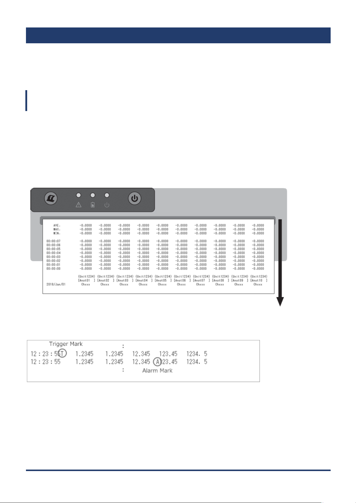
3.5 Logging Printing
Numeric values are printed with the channels in columns and the times in rows in the form of
CSV data. The maximum, minimum, and average values are printed in the last row. The print
direction is different between direct logging and memory out logging.
During direct logging
Direct logging printing is only supported on the GL240 and GL840. Direct logging printing is
performed when data is printed with the screen mode set to digital display. The fastest print
sampling speed is 1 second. Decimation is performed at data sampling settings faster than 1
second. Logic nor pulse signals cannot be printed.
On the GL840, the channel set on the information channel is printed. For the information
channel setting, see “Information channel setting” in chapter 4, “Configuration.”
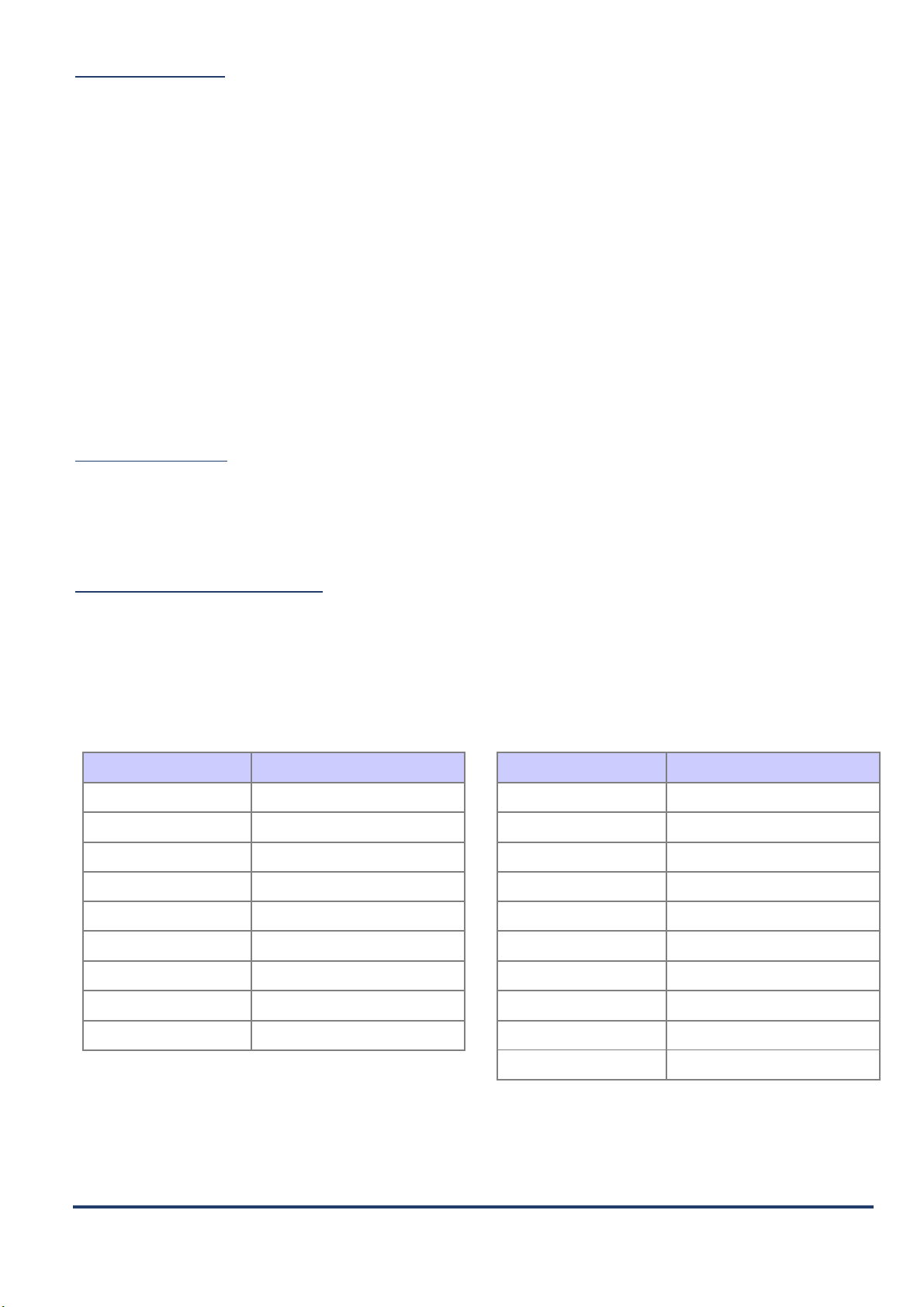
A “T” mark is printed next to the time in the row in which a trigger occurs. Moreover, an “A”
mark is printed in the channel of the row in which an alarm occurs.
※ If Trigger Sync is set to off and the sampling interval is set slower than 30 seconds, the
sampling interval will be offset near the start trigger because trigger detection is
performed at 30-second intervals.
17
Page 18

During memory out logging
Memory out logging printing is supported on the GL980, GL2000, GL240, and GL840.
During memory out logging, up to 1000 points can be output. A header is printed every 100
points. If you set full-width characters in annotations from the software, they will appear as
blanks. Logic nor pulse signals cannot be printed.
A “T” mark is printed next to the time in the row in which a trigger occurs. Moreover, an “A”
mark is printed in the channel of the row in which an alarm occurs.
18
Page 19

CAPTER 4 Configuration
4.1 OTHER menu
You can enable or disable the print function using the “Printer function” setting in the OTHER
(“OTH” on the GL240) menu. By default, the printer function is disabled. If you want to use it,
change this setting.
GL980/GL2000
GL840 GL240
19
Page 20

Options
Description
Off
The printer function is disabled. Printer parameters will be hidden.
USB
The printer is used with a USB connection. (GL980/GL2000 only)
LAN
The printer is used with a wired LAN connection.
(GL980/GL2000/GL840 only)
* To use a wired LAN connection, you need an off-the-shelf wireless
LAN router.
Wireless LAN
The printer is used with a wireless LAN connection. (GL840/GL240
only)
* To use a wireless LAN connection, you need a GL wireless LAN unit
(B-568).
To enable the setting, you need to specify “Access point” or “Station” on
the WLAN menu.
Printer function
Usage interface
Set the interface (I/F) that the printer will use.
GL980/GL2000 GL840 GL240
When you switch to an option other than Off, the printer menu appears.
Printer name
Enter the printer name or printer’s IP address.
The default printer name is “H-” followed by a serial number string. The printer and logger
must be connected within the same network.
20
Page 21

Example: If the serial number is “123456789012”, the printer name is “H-123456789012”.
If you want to use an IP address, enter the printer’s IP address.
Example: If the IP address is IP “192.168.0.100”, enter “192.168.0.100”.
Printer search
A search is made for printers existing in the same network. When printers are found, they are
shown in the printer list. When you select a printer, a connection is established. If no printers
are found, check the printer or network settings.
Print test
Printer tests can be performed to check whether the printer is connected properly.
If the printer is not connected properly, the following message appears in which case check
the settings.
21
Page 22

Information
When a printer is connected, you can view the printer information from the Information menu.
Printer information
You can view the printer firmware version, Power Supply, Battery level, and Print head
temperature.
22
Page 23

Options
Description
Off
The printer function is disabled.
On
The printer function is enabled.
4.2 Printer Menu (Y-T)
Printer
You can turn on or off the printer use. This setting can be changed only when the printer is free
running.
23
Page 24

Trigger Sync
Options
Description
Off
Printing is not synchronized to the trigger function. Printing starts
when recording starts.
On
Printing is performed in sync with sugar start and trigger stop.
You can turn on or off the Trigger Sync mode. For details on the print timing, see the next
section (Print timing).
Print timing
Print timing during Y-T recording
The print timing varies depending on the Trigger Sync setting. The following figure shows the
timings.
● Start trigger only
When Trigger Sync is set to off, printing is performed during the period from when recording is
started until it is stopped. When Trigger Sync is set to on, printing is performed during the
period from when the trigger condition is established until recording is stopped.
Even if recording stops in the middle the recording due to the disk or memory becoming full,
printing continues until you stop it. If stop trigger is specified when recording to internal RAM
(GL980/GL2000 only), see “Memory full (internal RAM)” under “In the case of start/stop
trigger.”
24
Page 25

In the case of start/stop trigger
In the case of start/stop trigger, the start timing is same as the start trigger. The stop key or
stop trigger stops not only the recording but also the printing. The following is a description of
what happens when the disk or memory becomes full.
<Disk full (extra memory, internal memory)>
If an external memory or internal memory is used, printing continues until the start key is
pressed or a stop trigger is received even if the recording stops due to the disk becoming full
between start and stop. During this period, the measuring instrument status shows that data
has been recorded.
<Memory full (internal RAM GL980/GL2000 only)>
If the recording destination is set to internal RAM and recording stops due to the memory
becoming full, printing also stops. Note that printing stops before the stop trigger point. This is
due to a limitation of the instrument.
25
Page 26

● When the start/stop trigger is set to repeat
Basically, start/stop trigger is repeated. Printing is paused before repeating starts. A few
milliseconds is inserted between the old recording and new recording, and printing is started
again from the beginning. Scale print and list print are not performed during a repeat period but
when printing finally stops.
Print timing during XY recording (GL980/GL2000 only)
On the XY screen when the printer set on, a hard copy is automatically made according to the XY
output format when recording stops.
26
Page 27

Sampling interval
Chart speed limitation
5 ms or less
25mm/s
10ms
10mm/s
20ms
5mm/s
50ms
2mm/s
100ms
1mm/s
200ms
30mm/min
500ms
10mm/min
1s
5mm/min
2s
2mm/min
Sampling interval
Chart speed limitation
5s
1mm/min
10s
30mm/h
20s
20mm/h
30s
10mm/h
1min
5mm/h
2min
2mm/h
5min
1mm/h
10min
10mm/day
-
External feeding
Chart speed
You can set the chart speed. There are restrictions on the chart speed depending on the
sampling interval. See the following table. You can change the chart speed even while printing
is in progress, but the printed waveforms will be discontinuous. During battery operation, the
maximum charge speed is limited to 5 mm/s. Set this parameter again if a switch is made
between AC operation and battery operation.
The charge speed can also be set from the monitor display.
Table of chart speeds and sampling limitations
27
Page 28
Time/DIV
Chart speed
500ms/DIV
20mm/s
1s/DIV
10mm/s
2s/DIV
5mm/s
5s/DIV
2mm/s
10s/DIV
1mm/s
20s/DIV
30mm/min
30s/DIV
20mm/min
1min/DIV
10mm/min
2min/DIV
5mm/min
Time/DIV
Chart speed
5min/DIV
2mm/min
10min/DIV
1mm/min
20min/DIV
30mm/h
30min/DIV
20mm/h
1hour/DIV
10mm/h
2hour/DIV
5mm/h
5hour/DIV
2mm/h
10hour/DIV
1mm/h
12hour/DIV
20mm/day
24hour/DIV
10mm/day
External feeding
When this setting is enabled, the external sampling function nor the external trigger function
can be used. For every external feeding clock cycle, the paper is fed by 0.125 mm. Chart speed
is limited by the sampling interval setting. Please refer to the "Table of chart speeds and
sampling limitations" for details.
When the sampling interval is 1 ms: Up to 200 pulses/s (25[mm/s] / 0.125[mm])
When the sampling interval is 200 ms: Up to 4 pulses/s (30[mm/min] / 0.125[mm])
The external feeding clock must be input to the trigger I/O sampling terminal. For the input
procedure, see the description of how to connect the GL I/O cable (B-513) and the function in
the instrument instruction manual.
Division function
When external feeding is specified, the division function is displayed. You can select Off, 1/2, or
1/4. If you set the division to 1/4, the chart is fed 0.125 mm or four clocks.
Fit to the screen Time/DIV
The following table shows the relationship between the Time/DIV settings and chart speeds.
However, the chart speed may be limited by the specified sampling interval. The function does
not work if chart speed is set to External.
Table for setting the chart speed according to the Time/DIV setting of the screen
28
Page 29

Grid type
The available print grid types are 5mm/10mm, fine, coarse, and Off.
10 mm fine grid 10 mm coarse grid
5 mm fine grid 5 mm coarse grid
29
Page 30

Envelope mode
Turning the envelope mode on and off
Envelope processing decreases the waveform printing rate in the fill areas to make other
waveforms easier to view as well as reduce the power consumption and increase the lifespan of
the thermal head.
Envelope mode off
Envelope mode on
Forced envelope mode
Envelope processing is forcibly performed according to the printing rate of the waveform data,
regardless of the envelope mode on/off setting, in order to protect the printer power supply and
thermal head. In this case, waveforms with high printing rate may be printed lightly, and the
vertical lines of square waves may not be printed. As a countermeasure, increase the range on
the instrument or increase the span to reduce the printer chart speed, thereby decreasing the
printing rate per unit time.
30
Page 31

Parameter
Description
Set
You can specify up to 10 sets of channel settings.
Reducing input
As a way of simplifying setup, the selected channel
range is applied to the analog channel column.
Analog
Select the analog channels to be printed.
CH: analog input
GS: GS sensor
WL: WL sensor
Pulse
Select the pulse channels to be printed.
The pulse menu is displayed only when pulse CH is
enabled. The pulse of the WL sensor of GL100 is set
here.
OK
Applies the settings and closes the window.
Cancel
Closes the window without applying the settings.
Analog
Information channel settings
The GL840 can print up to maximum 10 analog channels + 4 pulses.
Only on the GL840, select the channels to be printed using the information channel settings.
The settings apply to logging print, annotation print, scale print, and list print.
Logic nor pulse signals cannot be printed in logging printing.
The initial value is CH1 to CH10.
31
Page 32

Annotation settings
Specify the annotation settings.
Print interval
Set the annotation print interval. Set the print interval between 10 cm and 100 cm.
Flying annotation
This function performs annotation title printing at the timing of your choice through a command
button from the menu or remote command. For a description of how to use remote commands,
see “Flying annotation I/F commands,” provided later. For further details, see the I/F
Command Specifications.
Flying annotation print example 1
When flying annotation is executed, printing starts.
Flying annotation print example 2
If flying annotation is executed while annotation printing is in progress, the printing is paused.
When the printing of the current annotation is completed, printing is resumed.
32
Page 33

Flying annotation print example 3
If the title print is changed while annotation printing is in progress, the change is applied from the
next print.
Flying annotation print example 4
If title print is changed and flying annotation is executed while annotation printing is in progress,
the change and printing are paused. When the printing of the current annotation is completed,
printing is resumed with the new title.
Flying annotation I/F commands
33
Page 34

Setting
Printed content
System
The date and time and chart speed for annotation
printing are printed.
User
The user-defined character string (up to 31
characters) is printed.
System + user
The date and time, chart speed, and user-defined
character string are printed.
Setting
Printed content
AMP
The amp setting, input, range, and filter of the target
channel are printed.
User
The user-defined character string (up to 31
characters) specified using AMP settings > Others >
Annotation is printed.
AMP + user
The user-defined character string is printed after AMP
printing.
Measured values
The measure values during annotation printing are
printed.
Title print
Date and time, chart speed character string, and user-defined character string can be printed.
Title print printout example
Channel print
AMP setting, user-defined character string, measured values, and the like can be printed.
Pulse channel annotation print is available only on the GL980/GL2000.
Channel print printout example
※ On the GL840, only the channel set on the information channel is printed.
34
Page 35

Parameter
Description
Off
Timing markers are not printed.
1sec, 10sec, 1min,
10min, 1h, 10h
Timing markers are printed according to the
specified time interval.
Parameter
Description
Off
Distance markers are not printed.
On
Distance markers are printed.
Marker/mark settings
Set the mark function for supplementing printouts.
Timing marker
This function prints time lines according to the specified time interval. This cannot be enabled
simultaneously with the distance marker.
Print example
Distance marker
The distances (cm) are printed every 5 cm from the start of printing. This cannot be enabled
simultaneously with the timing marker.
This is always printed during memory out printing.
Print example
35
Page 36

Parameter
Description
Off
Channel marks are not printed.
On
Channel marks are printed.
Parameter
Description
Off
Alarm printing is not performed.
On
Alarm printing is performed.
Channel marks
This function prints channel numbers above the Y-T waveform. They are printed only on
channels whose amp setting is enabled.
Print example
Alarm printing
This is printed when an alarm occurs. If alarms overlap, the alarm printing in progress is
canceled, and the printing of the alarm that occurred later overwrites the printing of the older
alarm. If alarms occur on multiple channels simultaneously, printing is performed only for the
channel with the smallest channel number. Further, the ▲ mark is replaced with an overlap
mark.
Print example
36
Page 37

Parameter
Description
Off
Scale printing is not performed.
On
Scale printing is performed.
<Upper value>
<Lower value>
<Zero position>
Scale printing
The scale of each channel is printed after Y-T printing. On the GL840, the channel specified in
the information channel settings is printed.
Print example
37
Page 38

Parameter
Description
Off
List printing is not performed after Y-T printing is
complete.
On
List printing is performed after Y-T printing is
complete.
List printing
Set whether to perform list printing after Y-T printing is complete. When you press the execute
button, list printing is performed immediately.
Print example
38
Page 39

Options
Description
Off
The printer function is disabled.
On
The printer function is enabled.
Options
Description
Waveform screen
Only the waveform area is printed.
All screens
The entire screen is printed just like a normal screen printout.
All Screens
(B/W reverse)
The black and white of the entire screen is reversed and printed.
Options
Description
Off
Scale printing is not performed.
4.3 Printer Menu (XY)
GL980/GL2000 only
You can set this when the display mode is XY.
Printer settings
You can turn on or off the printer.
XY output format
Set the output format of the screen printout.
Grid type
The available print grid types are 5mm/10mm, fine, coarse, and Off. This is the same as the Y-T
display.
Scale printing
This can be enabled only when the XY output format is set to Waveform only.
Set whether to print the scale (numeric values and axis channels).
39
Page 40

On (top)
Scale printing is performed at the top of the screen.
On (bottom)
Scale printing is performed at the bottom of the screen.
Parameter
Description
Off
List printing is not performed after XY printing is
complete.
On
List printing is performed after XY printing is
complete.
Print example
On (top)
On (bottom)
List printing
Set whether to perform list printing after XY printing is complete. When you press the execute
button, list printing is performed immediately.
40
Page 41

4.4 File Menu
This section describes the printer settings in the file menu.
GL980/GL2000
GL240
GL840
Screen printout
The contents displayed on the screen are printed on the printer.
The color information is converted into black-and-white and output.
When you press the execute button, printing starts. This cannot be executed while printing is
already in progress.
Printing in XY mode is the XY output format setting in the printer menu. (GL980/GL2000 only).
If you execute black-and-white inversion, printing is performed with white and black inverted.
41
Page 42

4.5 Function Key (GL980/GL2000 only)
This section describes the printer functions that can be used with the FUNC key.
Screen printout
When you press the FUNC key when the printer is enabled, a function menu is displayed, and
you can print the screen.
The printed content is the same as the screen printing of the file menu.
42
Page 43

4.6 Menu during Data Playback
Y-T
This section describes the printer menu during recorded data playback. Unlike the Y-T printing
during recording, during playback, printing is performed by expanding or reducing the
waveforms according to the Time/DIV setting of the screen. Each mark print can be changed
with the printer settings.
GL980/GL2000
GL240
GL840
While print data is being output to the printer, a dialog box appears showing the progress. If
you press the QUIT button to cancel printing, printing is performed up to that point. Data
already transmitted to the printer is printed even after you cancel printing.
43
Page 44

All data Y-T printout
The entire data being played back is printed.
Cursor Y-T printout
Data between the cursors being played back is printed.
Cursor logging printout
Logging printout is performed on the data between the cursors being played back.
※ You cannot control the logger while the print data is being transmitted to the printer.
※ If you attempt to perform the next printout while printing is in progress, the following
message appears, and you cannot print.
Printer settings
The changes to the settings you make while printing is in progress are not applied immediately.
There are applied to the next print.
Same as direct mode. Grid type, envelope mode, channel mark, alarm print, scale print, list
print
※ Check
Annotations are not printed when a CSV data file recorded with the printer function turned off is played
back. If you want to print annotations also during playback, turn the printer function on and then
perform data recording. Annotations are always printed with GBD data files.
44
Page 45

XY print
GL980/GL2000 only
You can set this when the display mode is XY.
This is the same function as Direct XY.
Screen printout
Screen printouts are possible from the monitor display during XY display. Printing starts by
moving the cursor to “Screen Printout” and pressing the Enter key.
During free running recording
During playback
45
Page 46

Item
Specifications
Compatible model
midi LOGGER GL980
midi LOGGER GL2000
midi LOGGER GL840
midi LOGGER GL240
Printer-compa
tible firmware
version
GL980/GL2000
Ver.1.30 or later
GL840
Ver.1.50 or later
GL240
Ver.1.50 or later
Connection
method
GL980/GL2000
USB connection, Wired LAN connection
GL840
Wireless LAN connection, Wired LAN connection
GL240
Wireless LAN connection
Item
Specifications
Y-T waveform
Chart speed
1, 2, 5, 10, 20, 25 mm/s
1, 2, 5, 10, 20, 25, 30, 50, 100 mm/min
1, 2, 5, 10, 20, 25, 30, 50, 100 mm/h
10, 20 mm/day, external
• Asynchronous to the TIME/DIV setting of the GL
screen.
• Limitations present due to sampling.
• A function available for setting the chart speed to
that equivalent to the TIME/DIV setting of the GL
screen.
* On the GL240/GL840, the fastest speed is 10
mm/s during AC operation.
* The fastest speed is 5 mm/s on all models during
printer battery operation.
CAPTER 5 Specifications
5.1 Connection Specification
※ Do not use a USB hub or the like when making a USB connection.
※ To use a wired LAN connection, you need a separate off-the-shelf wireless LAN router.
※ Only a single logger can be connected to a printer.
5.2 Print Functions
Page 47

Trigger Sync
Off/On
Record format
Fix to 200 mm x 1
Zone function
Follows the zone function setting of the GL screen.
However, during printout, the 10 DIV full-scale
display on the screen is output at 20 DIV.
Grid
10mm fine/coarse, 5mm fine/coarse, OFF
Span/position
According to the GL
Annotation
Title print: prints the date and time, chart speed,
and user-defined character string.
Channel print: prints channel annotation, amp
setting, and measured values.
In addition, flying annotation is supported.
* Only the characters that can be input from the
setting menu can be printed.
*Double-byte characters are printed as spaces.
* The GL840 prints up to 10 channels that you
specify.
Channel marks
On/Off
Distance mark
On/Off (every cumulative display/5cm from start)
Select either the distance mark or timing marker.
Timing marker
Off, 1sec, 10sec, 1min, 10min, 1h, 10h
Select either the timing marker or distance mark.
Alarm printing
On/Off *Prints perpendicular to the feed direction.
Envelope mode
On/Off
Trigger mark
On/Off
Scale printing
On/Off * The GL840 prints up to 10 channels that
you specify.
Logging printing
Direct logging printing, memory out logging
printing.
* Direct logging printing is available only on the
GL840/GL240.
Direct logging printing is performed when data is
printed with the GL840/GL240 screen is set the
digital.
* For direct logging, the fastest print sampling
interval is 1 second. If the data sampling interval is
set faster than 1 second, the data is decimated.
* The GL840 prints up to 10 channels that you
specify.
Page 48

* Logic nor pulse signals cannot be printed.
XY print
(GL980/GL200
0 only)
Function
Hard copy of the GL screen
Output type
Waveform screen / All screens / All screens (B/W
reverse)
Screen
printout
Gradation
Dither method
Function
Hard copy of the GL screen
Black-and-white
inversion
Follows the background color setting of the GL
screen.
List printing
Available
Print timing
Direct Y-T printing
When the GL screen is set to Y-T.
Between start and stop, trigger sync/async mode.
(with trigger marks)
Y-T memory out
printing
Specify all data or between cursors from the
execution menu during Y-T playback.
(Not supported during the dual screen playback)
Direct logging printing
(GL240/GL840 only)
When the GL screen is set to digital display.
Between start and stop, trigger sync/async mode.
Memory out logging
printing
Specify the range between cursors from the
execution menu during Y-T playback (up to 1000
points).
XY printing
(GL980/GL2000 only)
Hard copy of the GL screen
Integration bar graph
printing
(GL240/GL840 only)
Hard copy of the GL screen
External feed function
Available
Select external sampling, external trigger, or
external feeding.
* A clock signal must be applied to the trigger
input/external sampling terminal of the GL.
Page 49

Page 50

Specifications are subject to change without notice.
Thermal Printer Function Manual
GL-PRINTER-UM-151
July 12, 2019 1st edition-01
Page 51

 Loading...