

Page 1

CSX500 SERIES
MANUAL NO.CSX500-UM-152
USER’S MANUAL
IMAGE SCANNER
Page 2

TO ENSURE SAFE AND CORRECT USE
Danger
Warning
Caution
• To ensure the safe and correct use of your Image Scanner, read this manual thoroughly prior to use.
• After reading this manual, store it in a safe place for reference as necessary.
• Do not allow small children to touch the Image Scanner.
• The following describes important points for safe operation. Be sure to observe them strictly.
Conventions Used in This Manual
To ensure the safe and correct use of the Image Scanner as well as to prevent human injury and
property damage, the safety precautions provided in this manual are ranked into the three categories
described below. Be sure to gain a full understanding of the difference between each of the categories
before reading the manual.
This category provides information that, if ignored, is highly likely to
cause fatal or serious injury to the operator.
This category provides information that, if ignored, is likely to cause
fatal or serious injury to the operator.
This category provides information that, if ignored, could cause
injury to the operator or physical damage to the Image Scanner.
Description of Safety Symbols
The symbol indicates information that requires careful attention
(including warnings). The specic point requiring attention is described
by an illustration or text within or next to the symbol.
The symbol indicates an action that is prohibited. Such prohibited
action is described by an illustration or text within or next to the
symbol.
The symbol indicates an action that must be performed. Such
imperative action is described by an illustration or text within or next to
the symbol.
i
Page 3

ii
SAFETY PRECAUTIONS
Warning
Thinner
Benzine
Caution
To ensure the safe and correct use of your Image Scanner, be sure to observe the following points.
Installation Precautions
Do not install the scanner in the vicinity of volatile
solvents such as alcohol or thinner.
• A volatile solvent coming into contact with any of the internal
electrical components may result in a re hazard or electric shock.
Do not place objects such as those listed below on top
of the scanner.
• Objects such as these coming into contact with any of the internal
electrical components may result in a re hazard or electric shock.
♦ Metallic objects such as necklaces
♦ Objects such as glasses, vases, houseplants, etc. that contain
water or other uids
If any of these objects does come into contact with the internal
electrical components immediately turn off the power, remove the
plug from the power outlet, and either contact the store where you
purchased your scanner or your nearest Graphtec representative.
Do not use the scanner in an unstable location such
as on a slope or a location that is subject to a lot of
vibration.
• Such locations may cause the scanner to tip over and cause
injuries.
Do not place heavy objects on the scanner.
• Such objects may tip over or fall off, causing injuries.
Do not use sharp, pointed articles on the scanner.
• Such action may impair the scanner’s performance and cause the
scanner to malfunction or break down.
Page 4

When using the scanner on a desktop
At least 300 mm
At least 200 mm
At least
300 mm
At least
300 mm
Do not exert pressure on the scanner.
• Such action may impair the scanner’s performance and cause the
scanner to malfunction or break down.
• Such action could cause injury to the operator.
Avoid installing the scanner in any of the following
locations.
• Use in such locations may result in a re hazard or electric shock.
♦ Excessively humid or dusty locations
♦ Locations exposed to direct sunlight
♦ Locations exposed to high temperatures
♦ Locations near ames or moisture
Do not install, use, or store the scanner in a location that
does not meet the specied temperature and humidity
ranges.
• Such location may impair the scanner’s performance due to
deformation or damage, and cause the scanner to malfunction or
break down.
Do not install, use, or store the scanner in a location
subject to excessive mechanical vibration or electrical
noise.
• Such location may impair the scanner’s performance and cause
the scanner to malfunction or break down.
Leave plenty of space around the scanner.
• Leave sufcient space for operations in front of and behind the
scanner.
iii
Page 5

iv
Power Supply Precautions
Warning
Do not damage the power cable, or modify it in any way.
Moreover, do not place heavy objects on the power
cable, pull on the cable, or bend it excessively.
• There may be current leakage from the damaged parts, resulting
in a re hazard or electric shock.
• Do not unplug or plug in the power cable when your hands are
wet. Such action may result in electric shock.
Do not connect multiple devices to the same power
outlet.
• Use of the scanner in such a condition may result in a re hazard
or electric shock.
Do not bundle or tie-wrap the power cable.
• Use of a bundled power cable may result in a re hazard or electric
shock.
Make sure that the power cable is rmly inserted into the
power outlet.
• Use of a power cable when the plug is not completely inserted into
the power outlet may result in a re hazard or electric shock.
Do not use a power cable other than the one supplied
with your scanner.
• Use of a different power cable may result in a re hazard or
electric shock.
Page 6

Caution
Prohibited
Specified
rating
Do not connect the scanner to a non-rated power supply.
• Use of a different supply voltage may result in electrical shock or a
re hazard due to current leakage.
Before disconnecting or reconnecting the power cable,
be sure to turn off the scanner.
• Failure to do so may impair the scanner’s performance and cause
the scanner to malfunction or break down.
• Failure to do so may result in electric shock.
When disconnecting the power cable, be sure to hold on
to the plug, and not pull on the cable itself.
• Pulling on the cable will expose the core wires, or cause damage
such as broken wires. Current leakage from the exposed or
damaged areas may result in a re hazard or electric shock.
Before cleaning the scanner, be sure to unplug the power
cable from the power outlet.
• Failure to do so may result in electric shock.
Do not allow dust or metallic matter to adhere to the
power plug.
• If the power plug becomes dirty, thoroughly wipe it clean.
• The use of a dirty power plug may result in a re hazard or electric
shock.
As a general rule, do not use an extension cord.
• Use of an extension cord may result in a re hazard or electric
shock.
If you must use an extension cord, unbundle it, and make sure that
the power plug is rmly inserted into the extension cord socket.
Make sure that the power plug can be readily unplugged
at any time, and that there are no objects placed in its
vicinity.
• Objects placed in the vicinity of the power plug will prevent its
removal in an emergency.
v
Page 7

vi
Handling Precautions
Warning
Do not disassemble or modify the scanner.
• Such actions may result in a re hazard or electric shock.
If the scanner makes an unusual noise, generates smoke,
overheats, emits a strange odor, or otherwise functions
abnormally, immediately turn off the power, remove the
plug from the power outlet, and either contact the store
where you purchased your scanner or your nearest
Graphtec representative.
• Use of the scanner in such a condition may result in a re hazard
or electric shock.
Do not use ammable aerosols or similar products in the
vicinity of the scanner.
• The gas contained in the spray may cause a re hazard or electric
shock if it comes into contact with the scanner’s internal electrical
components.
Before moving the scanner, make sure that the main
power switch is in the “off” position and that the power
plug has been removed from the power outlet.
• If the scanner is moved while it is still plugged into the power
outlet, the power cable may be damaged and cause a re hazard
or electric shock.
If the scanner is damaged from being dropped or other
impact, turn off its power and remove the power plug
from the power outlet.
• Use of the scanner in such status may result in a re hazard or
electric shock.
• Request repair by contacting the store where you purchased your
scanner or your nearest Graphtec representative.
• Never try to perform repair yourself. Repair work by inexperienced
personnel is extremely dangerous.
Page 8

Caution
Take care not to drop metallic items such as paper
clips or staples, or spill water, other uids or ammable
solvents (alcohol, benzene, thinner, etc.) inside the
scanner.
• Metallic items or uids coming into contact with the internal
electrical components may result in a re hazard or electric shock.
If such items or uids fall or are spilled inside the scanner,
immediately turn off the power, remove the power plug from the
power outlet and either contact the store where you purchased
your scanner or your nearest Graphtec representative.
Do not insert your hands inside the scanner during a
scanning operation or when a document is being fed.
• Moving parts inside the scanner may cause injuries.
If the scanner will not be used for an extended length of
time, such as at night, turn off the main power switch as
a safety precaution.
• In addition, if the scanner will not be used for longer periods of
time, such as a long weekend, remove the power plug from the
power outlet as an additional safety precaution.
vii
Page 9

viii
Maintenance and Inspection Precautions
Warning
Neutral
Detergent
Caution
Be sure to turn off the power and remove the power plug
from the power outlet before performing any cleaning
operations.
• Failure to do so may result in a re hazard or electric shock.
Moreover, there is a risk of injury if the scanner starts to move
during a cleaning operation.
To clean the scanner, use a cloth that has been
dampened with neutral detergent and then well wrung
out. Do not use volatile solvents such as alcohol,
benzene or thinner to clean the scanner.
• A volatile solvent coming into contact with any of the internal
electrical components may result in a re hazard or electric shock.
Do not attempt to lubricate the scanner’s mechanisms.
• Such action may impair the scanner’s performance and cause the
scanner to malfunction or break down.
• Such action may cause a re hazard or electric shock due to a
short circuit or overheating.
At least once a year, remove the power plug from the power outlet and clean the
prongs and surrounding areas.
• A build-up of dust may result in a re hazard.
When cleaning or checking the inside of the scanner, make sure that metallic objects
such as a necklace or bracelet do not come into contact with any of the internal
components.
• Such actions may result in injuries or an electric shock.
When removing a document that has become jammed inside the scanner, take care
not to cut your ngers on the edges of the document.
• Such actions may result in injuries.
Page 10

WARNING
Only computers or peripherals (computer input/output devices, terminals, printers, etc.)
certied as complying with the limits for a Class B digital device, pursuant to Part 15 of the
FCC Rules, may be attached to this product when this product is operated in a residential
environment. Operation with non-certied peripherals is likely to result in interference to
radio and TV.
FED ER AL CO MM UN IC ATI ONS COM M IS SI ON R A DI O FRE QU EN CY
INTERFERENCE STATEMENT
"This equipment has been tested and found to comply with the limits for a Class B digital
device pursuant to Part 15 of the FCC Rules. These limits are designed to provide
reasonable protection against harmful interference in a residential installation.
This equipment generates, uses, and can radiate radio frequency energy and, if not
installed and used in accordance with the instructions, may cause harmful interference
to radio communications. However, there is no guarantee that interference will not occur
in a particular installation. If this equipment does cause harmful interference to radio or
television reception, which can be determined by turning the equipment off and on, the user
is encouraged to try to correct interference by one or more of the following measures:
• Reorient or relocate the receiving antenna.
• Increase the separation between the equipment and receiver.
• Connect the equipment into an outlet on a circuit different from that to which the receiver is
connected.
• Consult the dealer or an experienced radio/TV technician for help."
ix
Page 11

INTRODUCTION
Thank you for choosing the Graphtec CSX500 Series Image Scanner.
Please read this manual thoroughly before attempting to use your new product to ensure that you use
it safely and correctly.
Notes on this Manual
(1) No part of this publication may be reproduced, stored in a retrieval system, or transmitted, in any
form or by any means, without the prior written permission of Graphtec Corporation.
(2) The product specications and other information in this manual are subject to change without
notice.
(3) While every effort has been made to provide complete and accurate information, please contact
your nearest Graphtec representative if you nd any unclear or erroneous information or wish to
make other comments or suggestions.
(4) Notwithstanding the stipulation in the preceding paragraph, Graphtec Corporation assumes no
liability for damages resulting from either the use of the information contained herein or the use of
the product.
Registered Trademarks
All names of companies, brands, logotypes, and products appearing in this manual are the trademarks
or registered trademarks of their respective companies.
Copyright
This User’s Manual is copyrighted by Graphtec Corporation.
International ENERGY STAR® Program
As an ENERGY STAR®* Partner, Graphtec. has determined that this product
meets the ENERGY STAR® guidelines for energy efciency.
* The International ENERGY STAR® Ofce Equipment Program is a global
program that promotes energy saving through the use of computer and other
ofce equipment. The program backs the development and dissemination of
products with functions that effectively reduce energy consumption. It is an open
system in which businesses can participate voluntarily. The targeted products
are ofce equipment such as computers, monitors, printers, faxes, copiers. Their
standards and logos are uniform among participating nations.
I
Page 12

Usage precautions
OK
NG
Top cover section
<Closing the top cover>
Keep your hands away from the front of the
scanner when closing the top cover.
<Opening the top cover>
Do not hold the rear section of the
top cover when opening it.
Top cover
Document guides
Top cover
Do not lift or move the scanner by holding the top cover section, as doing so may damage the scanner.
Always lift the scanner by holding the underside.
Take care not to get your ngers caught in the gap between the top cover and the scanner unit when
opening and closing the top cover.
When closing the top cover, please be careful not to pinch the document guides.
Always ensure that you open the top cover and remove the cushion material before using the scanner.
(See Section 4.1, “Opening and Closing the Top Cover”.)
Scanner warm-up
A warm-up period is not usually required for the CSX500 Series. However, if you plan to scan a color
document (in particular a document with many light colors), we recommend that you allow the scanner
to warm up for 10 minutes before scanning the document.
II
Page 13

CONTENTS
TO ENSURE SAFE AND CORRECT USE . . . . . . . . . . . . . . . . . . . . . . . . . . . . . . . . . . . . . . . . .i
Conventions Used in This Manual . . . . . . . . . . . . . . . . . . . . . . . . . . . . . . . . . . . . . . . . . . . . . . . . . . . . i
Description of Safety Symbols . . . . . . . . . . . . . . . . . . . . . . . . . . . . . . . . . . . . . . . . . . . . . . . . . . . . . . . i
SAFETY PRECAUTIONS . . . . . . . . . . . . . . . . . . . . . . . . . . . . . . . . . . . . . . . . . . . . . . . . . . . . . ii
Installation Precautions . . . . . . . . . . . . . . . . . . . . . . . . . . . . . . . . . . . . . . . . . . . . . . . . . . . . . . . . . . . .ii
Power Supply Precautions . . . . . . . . . . . . . . . . . . . . . . . . . . . . . . . . . . . . . . . . . . . . . . . . . . . . . . . . . iv
Handling Precautions . . . . . . . . . . . . . . . . . . . . . . . . . . . . . . . . . . . . . . . . . . . . . . . . . . . . . . . . . . . . . vi
Maintenance and Inspection Precautions . . . . . . . . . . . . . . . . . . . . . . . . . . . . . . . . . . . . . . . . . . . . viii
INTRODUCTION . . . . . . . . . . . . . . . . . . . . . . . . . . . . . . . . . . . . . . . . . . . . . . . . . . . . . . . . . . . . I
Notes on this Manual . . . . . . . . . . . . . . . . . . . . . . . . . . . . . . . . . . . . . . . . . . . . . . . . . . . . . . . . . . . . . . I
Registered Trademarks. . . . . . . . . . . . . . . . . . . . . . . . . . . . . . . . . . . . . . . . . . . . . . . . . . . . . . . . . . . . . I
Copyright . . . . . . . . . . . . . . . . . . . . . . . . . . . . . . . . . . . . . . . . . . . . . . . . . . . . . . . . . . . . . . . . . . . . . . . . I
International ENERGY STAR® Program . . . . . . . . . . . . . . . . . . . . . . . . . . . . . . . . . . . . . . . . . . . . . . . I
Usage precautions . . . . . . . . . . . . . . . . . . . . . . . . . . . . . . . . . . . . . . . . . . . . . . . . . . . . . . . . . . . . . . . II
Scanner warm-up . . . . . . . . . . . . . . . . . . . . . . . . . . . . . . . . . . . . . . . . . . . . . . . . . . . . . . . . . . . . . . . . II
CHAPTER 1 BEFORE USING THE SCANNER
1.1 Checking the Contents of the Package . . . . . . . . . . . . . . . . . . . . . . . . . . . . . . . . . . . . . . 1-1
1.2 Part Names and Functions . . . . . . . . . . . . . . . . . . . . . . . . . . . . . . . . . . . . . . . . . . . . . . . . 1-2
Front View/Control Panel . . . . . . . . . . . . . . . . . . . . . . . . . . . . . . . . . . . . . . . . . . . . . . . . . . . . . . . . . 1-2
Rear View . . . . . . . . . . . . . . . . . . . . . . . . . . . . . . . . . . . . . . . . . . . . . . . . . . . . . . . . . . . . . . . . . . . . .1-3
1.3 Assembling the Scanner . . . . . . . . . . . . . . . . . . . . . . . . . . . . . . . . . . . . . . . . . . . . . . . . . 1-4
Attaching the document suppor t plates . . . . . . . . . . . . . . . . . . . . . . . . . . . . . . . . . . . . . . . . . . . . . . 1- 4
Attaching and using the cable clamp . . . . . . . . . . . . . . . . . . . . . . . . . . . . . . . . . . . . . . . . . . . . . . . . 1-4
CHAPTER 2 CONNECTION AND PREPARATIONS
2.1 Connecting to the Power Supply . . . . . . . . . . . . . . . . . . . . . . . . . . . . . . . . . . . . . . . . . . . 2-1
2.2 Turning the Power On and Off . . . . . . . . . . . . . . . . . . . . . . . . . . . . . . . . . . . . . . . . . . . . . 2-2
Turning the Power On . . . . . . . . . . . . . . . . . . . . . . . . . . . . . . . . . . . . . . . . . . . . . . . . . . . . . . . . . . . .2-2
Turning the Power Off . . . . . . . . . . . . . . . . . . . . . . . . . . . . . . . . . . . . . . . . . . . . . . . . . . . . . . . . . . . . 2-2
Notes on the power-saving mode . . . . . . . . . . . . . . . . . . . . . . . . . . . . . . . . . . . . . . . . . . . . . . . . . . . 2-3
2.3 System Requirements . . . . . . . . . . . . . . . . . . . . . . . . . . . . . . . . . . . . . . . . . . . . . . . . . . . 2- 4
2.4 Connecting the Scanner to a Computer . . . . . . . . . . . . . . . . . . . . . . . . . . . . . . . . . . . . . . 2-5
USB Connection . . . . . . . . . . . . . . . . . . . . . . . . . . . . . . . . . . . . . . . . . . . . . . . . . . . . . . . . . . . . . . . .2-5
Network Connection (CSX550-09 only) . . . . . . . . . . . . . . . . . . . . . . . . . . . . . . . . . . . . . . . . . . . . . .2-6
2.5 Installing the Scanner Driver Software . . . . . . . . . . . . . . . . . . . . . . . . . . . . . . . . . . . . . . . 2-7
For Windows 7 . . . . . . . . . . . . . . . . . . . . . . . . . . . . . . . . . . . . . . . . . . . . . . . . . . . . . . . . . . . . . . . . . 2-7
For Windows Vista . . . . . . . . . . . . . . . . . . . . . . . . . . . . . . . . . . . . . . . . . . . . . . . . . . . . . . . . . . . . . 2-10
For Windows XP . . . . . . . . . . . . . . . . . . . . . . . . . . . . . . . . . . . . . . . . . . . . . . . . . . . . . . . . . . . . . . . 2-13
2.6 Installing the Scanning Master Pro Color Application . . . . . . . . . . . . . . . . . . . . . . . . . . 2-16
Operating environment . . . . . . . . . . . . . . . . . . . . . . . . . . . . . . . . . . . . . . . . . . . . . . . . . . . . . . . . . .2-16
Installation procedure . . . . . . . . . . . . . . . . . . . . . . . . . . . . . . . . . . . . . . . . . . . . . . . . . . . . . . . . . . . 2-16
2.7 Network Connection (CSX550-09 only) . . . . . . . . . . . . . . . . . . . . . . . . . . . . . . . . . . . . . 2-18
Installation procedure . . . . . . . . . . . . . . . . . . . . . . . . . . . . . . . . . . . . . . . . . . . . . . . . . . . . . . . . . . . 2-18
Device Setup Settings . . . . . . . . . . . . . . . . . . . . . . . . . . . . . . . . . . . . . . . . . . . . . . . . . . . . . . . . . .2-20
Installing the Graphtec Network Utility . . . . . . . . . . . . . . . . . . . . . . . . . . . . . . . . . . . . . . . . . . . . . . 2-22
Setting up the Graphtec Network Utility . . . . . . . . . . . . . . . . . . . . . . . . . . . . . . . . . . . . . . . . . . . . . 2-24
How to initialize the settings . . . . . . . . . . . . . . . . . . . . . . . . . . . . . . . . . . . . . . . . . . . . . . . . . . . . . .2-26
C-1
Page 14

C-2
CHAPTER 3 LOADING A DOCUMENT
3.1 Compatible Document Types . . . . . . . . . . . . . . . . . . . . . . . . . . . . . . . . . . . . . . . . . . . . . . 3 -1
Compatible Media Widths for Scanning . . . . . . . . . . . . . . . . . . . . . . . . . . . . . . . . . . . . . . . . . . . . . .3 -1
Compatible Media Lengths for Scanning . . . . . . . . . . . . . . . . . . . . . . . . . . . . . . . . . . . . . . . . . . . . . 3-1
Compatible Document Thicknesses for Scanning . . . . . . . . . . . . . . . . . . . . . . . . . . . . . . . . . . . . . .3-1
Compatible Media Grades for Scanning . . . . . . . . . . . . . . . . . . . . . . . . . . . . . . . . . . . . . . . . . . . . .3 -2
3.2 Loading a Document . . . . . . . . . . . . . . . . . . . . . . . . . . . . . . . . . . . . . . . . . . . . . . . . . . . . 3-3
How to use the document guides . . . . . . . . . . . . . . . . . . . . . . . . . . . . . . . . . . . . . . . . . . . . . . . . . . .3-3
3.3
Handling Documents According to their Material and Thickness . . . . . . . . . . . . . . . . . . . . . . . .
3.4 Distance Correction . . . . . . . . . . . . . . . . . . . . . . . . . . . . . . . . . . . . . . . . . . . . . . . . . . . . . 3-7
Adjustment method . . . . . . . . . . . . . . . . . . . . . . . . . . . . . . . . . . . . . . . . . . . . . . . . . . . . . . . . . . . . . .3-7
3.5 Using the Carrier Sheet . . . . . . . . . . . . . . . . . . . . . . . . . . . . . . . . . . . . . . . . . . . . . . . . . . 3-8
CHAPTER 4 DAILY MAINTENANCE
4.1 Opening and Closing the Top Cover . . . . . . . . . . . . . . . . . . . . . . . . . . . . . . . . . . . . . . . . 4-1
Opening the top cover . . . . . . . . . . . . . . . . . . . . . . . . . . . . . . . . . . . . . . . . . . . . . . . . . . . . . . . . . . . . 4-1
Closing the top cover . . . . . . . . . . . . . . . . . . . . . . . . . . . . . . . . . . . . . . . . . . . . . . . . . . . . . . . . . . . .4 -1
4.2 Cleaning the Feed Rollers . . . . . . . . . . . . . . . . . . . . . . . . . . . . . . . . . . . . . . . . . . . . . . . . 4-2
4.3 Cleaning the Document support Rollers . . . . . . . . . . . . . . . . . . . . . . . . . . . . . . . . . . . . . 4-3
4.4 Cleaning the Gap Rollers . . . . . . . . . . . . . . . . . . . . . . . . . . . . . . . . . . . . . . . . . . . . . . . . . 4-4
4.5 Cleaning the Push Rollers . . . . . . . . . . . . . . . . . . . . . . . . . . . . . . . . . . . . . . . . . . . . . . . . 4-5
4.6 Cleaning the Image Sensors (Transparent Contact Plates) . . . . . . . . . . . . . . . . . . . . . . . 4-6
4.7 Cleaning the Sensors . . . . . . . . . . . . . . . . . . . . . . . . . . . . . . . . . . . . . . . . . . . . . . . . . . . . 4-7
4.8 Removing a Jammed Document . . . . . . . . . . . . . . . . . . . . . . . . . . . . . . . . . . . . . . . . . . . 4-8
4.9 Scanner Adjustment . . . . . . . . . . . . . . . . . . . . . . . . . . . . . . . . . . . . . . . . . . . . . . . . . . . . . 4-9
Preparation and checks . . . . . . . . . . . . . . . . . . . . . . . . . . . . . . . . . . . . . . . . . . . . . . . . . . . . . . . . . .4-9
Launching the Scanner Adjustment Program. . . . . . . . . . . . . . . . . . . . . . . . . . . . . . . . . . . . . . . . . .4-9
Calibration . . . . . . . . . . . . . . . . . . . . . . . . . . . . . . . . . . . . . . . . . . . . . . . . . . . . . . . . . . . . . . . . . . . . 4-10
3-5
CHAPTER 5 TROUBLESHOOTING PROCEDURES
5.1 The scanner Is turned on but doesn’t operate at all . . . . . . . . . . . . . . . . . . . . . . . . . . . . . 5-1
5.2
5.3 The control panel’s red ERROR LED is lit . . . . . . . . . . . . . . . . . . . . . . . . . . . . . . . . . . . . 5-2
5.4 The control panel’s red ERROR LED is ashing . . . . . . . . . . . . . . . . . . . . . . . . . . . . . . . 5-2
5.5
5.6
5.7 The image quality has dropped . . . . . . . . . . . . . . . . . . . . . . . . . . . . . . . . . . . . . . . . . . . . 5-3
5.8 The scanned data is incorrectly aligned . . . . . . . . . . . . . . . . . . . . . . . . . . . . . . . . . . . . . . 5 -3
5.9
5.10 The color intensity of the image data differs . . . . . . . . . . . . . . . . . . . . . . . . . . . . . . . . . . 5-4
5.11
5.12
5.13 The scanned image data is distorted . . . . . . . . . . . . . . . . . . . . . . . . . . . . . . . . . . . . . . . . 5-5
5.14 The scanned image data is patchy . . . . . . . . . . . . . . . . . . . . . . . . . . . . . . . . . . . . . . . . . . 5-5
The scanner operates improperly after connection to the computer . . . . . . . . . . . . . . . . . . . . . . . .
The document isn’t properly fed to the initial scanning position . . . . . . . . . . . . . . . . . . . . . . . .
The scanned image data is completely white or completely black . . . . . . . . . . . . . . . . . . . . . . .
Smudges not appearing in the original document appear in the scanned data . . . . . . . . . . . . . . . . . . . . . . . . . . . .
The document length differs from the scanned data length . . . . . . . . . . . . . . . . . . . . . . .
Stripes or moire patterns which are not in the original document appear in the scanned data . . . . . . . . . . . . . . . . . . . . . . . . . . . . . . . . . . . . .
5-1
5-2
5-2
5-4
5-4
5-4
Page 15

5.15 The document cannot be fed correctly . . . . . . . . . . . . . . . . . . . . . . . . . . . . . . . . . . . . . . . 5 -5
5.16 Automatic Deskew is not performed correctly . . . . . . . . . . . . . . . . . . . . . . . . . . . . . . . . . 5-5
APPENDIX
Appendix A Options and Consumables . . . . . . . . . . . . . . . . . . . . . . . . . . . . . . . . . . . . . . . . . . A-1
Appendix B Specications . . . . . . . . . . . . . . . . . . . . . . . . . . . . . . . . . . . . . . . . . . . . . . . . . . . . A-2
Appendix C External Dimensions . . . . . . . . . . . . . . . . . . . . . . . . . . . . . . . . . . . . . . . . . . . . . . . A-5
INDEX . . . . . . . . . . . . . . . . . . . . . . . . . . . . . . . . . . . . . . . . . . . . . . . . . . . . . I-1
C-3
Page 16

1.1 Checking the Contents of the Package
Scanner unit ...1
USB cable ...1Cable clamp ...1
Power cable ...1
Driver software ...1 USER’S MANUAL ...1
Calibration sheet ...1
Cleaning paper ...1
Carrier sheet (A0) ...1
(CSX530/CSX550 only)
CSX500 SERIES
USER’S MANUAL
MANUAL NO.CSX500-UM-152
IMAGE SCANNER
Document support plates ...3
Document guides ...2
CHAPTER 1 BEFORE USING THE SCANNER
Check to conrm that all of the items shown below are present. If any item is missing, promptly contact
the store where you purchased your scanner or your nearest Graphtec representative.
Scanner unit Power cable Document guides Cable clamp USB cable
Document suppor t plates Calibration sheet Carrier sheet Cleaning paper
Driver software User's manual
1-1
Page 17

1-2
Control Panel
(5) POWER button/LED
(6) PAPER LED
(7) ERROR LED
(8) EJECT key
(9) STOP key
(3) Top cover open levers
(4) Document guides
(2) Paper sensors
(1) Top cover
1.2 Part Names and Functions
Front View/Control Panel
Front View
(1) Top cover ............................ Open the top cover to clean the document hold-down unit and
transparent contact plates.
(2) Paper sensors .................... These sense whether a document is present in the scanner.
(3) Top cover open levers ........ Press these levers to open the top cover.
If the top cover is opened during a scanning operation, the operation
will be stopped compulsorily.
(4) Document guides ............... Use these guides to determine the position of a document when you
load the document.
Control Panel
(5) POWER button/LED (blue)
................................. Controls the on/off status of the power supply to the scanner.
Lit: The scanner is turned on.
Flashing: Flashes when the scanner is in power-saving mode.
Unlit: The scanner is turned off.
(6) PAPER LED (green) ........... Lit: Lights when a document has been loaded.
Flashing: Flashes while image data is being scanned.
Unlit: Normal status (Local status).
(7) ERROR LED (red) .............. Lit: Lights to indicate a hardware error. (see Section 5.3)
Flashing: Lights to indicate a hardware error. (see Section 5.4)
Unlit: Normal status
(8) EJECT key .......................... Press this key to feed the document.
If this key is pressed when the scanner is in document-loaded status,
(9) STOP key ........................... Compulsorily stops scanning/feeding of the document.
the document-loaded status is canceled and the document is ejected
to the front of the scanner.
If this key is pressed after the scanning operation has been canceled
or after scanning of the document was halted partway through the
scanning operation, the document-loaded status is canceled and the
document is ejected to the rear of the scanner.
If the ERROR LED ashes when the top cover is in the closed status,
press this key to suspend the scanning operation and check whether a
paper jam has occurred.
Page 18

Rear View
(15) Document support plates
(16) Cable clamp
(14) Main power switch
(10) USB connector (13) Power inlet
(12) Reset button (for network)
(11) Network connector
Caution
(10) USB connector ................. Used to connect the USB interface cable.
(11) Network connector * ......... Used to connect the Network interface cable.
(12) Reset button (for network) *
................................. This will initialize the network environment. Use the Network Utility to
recongure your settings. (see Section 2.7)
(13) Power inlet ........................ Used to connect the power cable.
(14) Main power switch ............ Used to turn the main power supply on or off.
(15) Document support plates
................................. Used to support the document that is being ejected.
(16) Cable clamp ...................... Used to bundle the power cable and USB cable together and fasten
them in place.
CSX550-09 only
*
Both USB and network connection cannot be executed simultaneously. Please refrain
from connecting the USB cable and the network cable to a single computer at the same
time.
1-3
Page 19

1-4
1.3 Assembling the Scanner
Document support plateHooks
Checkpoint
Caution
Cable clamp attachment location
Please see the separate Stand Assembly Instruction Manual for instructions on how to assemble the
stand.
Attaching the document support plates
Always be sure to install the document support plates, irrespective of the type of documents to be
scanned.
(1) Take one of the document support plates provided, and insert its hooks into the slots at the rear of
the scanner. Insert the hooks from the top of the slots.
(2) Attach the other document support plates in the same manner.
Detach the document support plates when moving or packing the scanner. Lift the plates
up and out of the slots to detach them.
Attaching and using the cable clamp
Attach the cable clamp to the scanner, and then pass the power cable, USB cable and network cable
(CSX550-09 only) through the clamp to fasten them in place.
Be sure to attach the cable clamp to the scanner and use it to fasten the power cable,
USB cable and net work cable (CSX550- 09 only) in place. Failure to do so may af fect the
scanning operation.
Attaching the clamp
(1) Using a soft cloth that has been soaked in water or diluted neutral detergent and then rmly wrung
out, wipe off any dust or dirt on the surface of the attachment location before attaching the cable
clamp.
Page 20

(2) Wipe the area once again with a soft, dry cloth to thoroughly remove any traces of moisture.
Cable clamp
Latch
Power cable Network cable
USB cable
(3) Peel off the adhesive sticker on the rear of the clamp and then attach the clamp to the scanner.
Using the clamp
(1) Pull up the latch at the top of the cable clamp to open the clamp.
(2) Pass the power cable, the USB cable and the network cable (CSX550- 09 only) through the cable
clamp, and then close it.
1-5
Page 21

CHAPTER 2 CONNECTION AND PREPARATIONS
Power inlet
AC power outlet
Power cable
Caution
2.1 Connecting to the Power Supply
Connect one end of the power cable provided to the scanner’s power inlet and the other end to an AC
power outlet of the rated supply voltage.
Be sure to use the cable clamp provided with the scanner to fasten the power cable in
place. Please see “Attaching and using the cable clamp” in Section 1.3, “Assembling the
Scanner” for further details.
2-1
Page 22

2-2
2.2 Turning the Power On and Off
ON
ON
OFF
Checkpoint
Caution
The LED (blue) on the [POWER] button changes as follows to indicate the scanner's power supply
status.
• Unlit: The scanner is turned off.
• Lit: The scanner is turned on.
• Flashing: Flashes when the scanner is in power-saving mode.
Turning the Power On
(1) Connect the power cable.
(2) Turn on the main power switch (the I side).
(3) Press the [POWER] button on the scanner's control panel.
When the scanner is in the power-on status, the [POWER] button LED lights blue.
Turning the Power Off
Press the [POWER] button on the scanner's control panel.
When the scanner is in the power-off status, the [POWER] button LED is extinguished.
• After the scanner has been turned off, wait at least ve seconds before turning it on
again.
• If you do not plan to use the scanner for any length of time, turn off the main power
switch (the O side).
Do not turn of f the main power switch (the O side) on the rear of the scanner while the
scanner is the power-on status.
Page 23

Notes on the power-saving mode
To cancel the
power-saving mode
Checkpoint
The scanner automatically switches to power-saving mode (the blue LED on the power button ashes)
after approximately 13 minutes have elapsed without a document being loaded in the scanner. To
return the scanner to normal status (Local status), press either the [STOP] or the [EJECT] key.
If a document has been loaded in the scanner, the scanner will not switch to power-
saving mode.
2-3
Page 24

2-4
2.3 System Requirements
Checkpoint
The minimum system requirements for running the scanner’s hardware and software are listed below.
OS: Windows XP Professional/Home Edition
Windows Vista Ultimate/Business/Home Premium/Home Basic
Windows 7 Ultimate/Enterprise/Professional/Home Premium
PC: Environment that the OS is working properly
(Recommended environment
CPU: Dual Core or higher grade Memory: 3 GB or more)
Hard Disk Drive: Disk space amount that can contain the scanned-in data
Monitor: 1024 x 768 pixels, True Color display
Mouse
Network Interface: 10BASE-T/100BASE-TX/1000BASE-T
(to connect the scanner via the Network interface)
USB 2.0 Interface: that comes standard with your computer
(to connect the scanner via the USB interface)
If you want to scan in and edit grayscale or color data, you may need a memor y larger
than the recommended size.
Depending on the document, it may not be possible to scan in the images it contains or
the process may slow down even if the memory size is increased.
If you encounter such a problem, from the Scanning Master Pro Color ‘OPS115’ menu
select Tools menu > Options > General tab and enable "Use Work File". In addition,
enable "Specify Folder" and then specify a folder that contains sufcient available
space.
Page 25

2.4 Connecting the Scanner to a Computer
Important
Caution
Computer
USB interface connector
USB cable
• Make sure that the USB cable is rmly inserted into the interface connectors.
• The operation of the scanner cannot be guaranteed in the following cases:
♦ When the cable is connected to a USB hub or an add-on USB board.
♦ When you are using a custom-built computer or one that you have modied.
♦ When you are using a cable that is longer than 3 meters in length.
(Please use the USB cable that is provided with your scanner.)
• Do not per form any of the following actions:
♦ Remove or reinsert the cable while you are installing the driver.
♦ Remove or reinsert the cable while starting up the computer or the scanner.
♦ Remove or reinsert the cable while transferring data.
♦ Connect two or more scanners to a single computer.
Be sure to use the cable clamp provided with the scanner to fasten the USB cable and
the network cable (CSX550- 09 only) in place. Please see “Attaching and using the cable
clamp” in Section 1.3, “Assembling the Scanner” for further details.
USB Connection
A USB cable is used to connect the scanner to the computer, via the respective USB interface
connectors. The connectors at the computer and scanner ends of the USB cable have different
shapes.
Make sure that the cable is oriented correctly before making the connection.
2-5
Page 26

2-6
Network Connection (CSX550-09 only)
Caution
Checkpoint
Computer
Network connector
Reset button
(for network)
Network
Network cable
Network connector
POWER lampLINK lamp
Reset button
(for network)
Both USB and network connection cannot be executed simultaneously. Please refrain
from connecting the USB cable and the network cable to a single computer at the same
time.
• You will need a network (LAN) cables and network hub to connect via Network. You will
need to purchase them separately.
• Structures of the network equipment and necessity of the router function depends on
the environment. For description, refer to the manual of the equipment, check with the
manufacturer or the network administrator.
• The scanner is compliant with 10BASE-T/100BASE-TX/1000BASE-T. Check your network
environment.
A Network cable is used to connect the scanner to the computer, via the respective Network interface
connectors.
Network Connector
After turning the scanner’s power on, conrm that the POWER lamp (right side) is ashing yellow.
LINK lamp (left side) ashes orange when connected to the 10Base-T/100Base-TX, and green when
connected to the 1000BASE-T.
Reset Button (for network)
This is used when the network environment has changed.
Turning the power on while pressing the reset button will cause the network environment to be
initialized.
Use the Network Utility to recongure your settings. (see Section 2.7)
Page 27

2.5 Installing the Scanner Driver Software
Checkpoint
The procedure outlined below is based on the requirement that you are logged on to
Windows with administrator rights. Consult your Windows manual and Windows Help for
more information.
For Windows 7
(1) Turn on the computer. (Do not connect the scanner yet.)
(2) Insert the "IMAGE SCANNER USER GUIDE CD-ROM," which came with the scanner, into the
CD-ROM drive.
AutoPlay screen will appear shortly. Select [Run MultiSetup.exe] from there.
(3) The User Account Control screen is displayed. Click [Yes] to proceed with the installation.
(4) The “Setup menu” screen starts automatically. Next, select the "Pre-install the scanner driver"
button.
If the “Setup menu” screen does not start, open Windows Explorer, and double-click on
"MultiSetup.exe" within the CD-ROM folder.
2-7
Page 28

2-8
(5) The screen shown below appears. Click the [Next] button
Checkpoint
(6) The screen shown below is displayed. Click [Install] to proceed with the installation.
(7) The screen shown below is displayed when the wizard has nished installing the driver. Click the
[Finish] button to close the “Device Driver Installation Wizard”.
(8) Turn on the scanner, and then the scanner connects to the computer.
(9) The following message appears on the taskbar when you connects to the scanner. Wait for the
driver installation is nished. (It may take several minutes.)
• If the computer is not connected to the net work, the installation nishes immediately,
and the message from the next step [10] appears on the screen.
• If the computer is connected to the network, this message may disappear during the
installation. In this case, wait until the message from the next step [10] appears on the
screen.
• The following screen appears when you click the message. In this case, by selecting
the "Skip obtaining driver sof tware from Windows Update" link the installation can be
nalized early.
Page 29

(10) The following message appears on the taskbar when the driver installation is nished.
Checkpoint
After clicking the taskbar message in step [9] the following screen appears when the
driver installation is nished.
(11) Select "Devices and Printers" using the [Start] menu on the Windows desktop to display the
screen shown below. Check that connected scanner is displayed here.
The installation of driver software is complete.
2-9
Page 30

2-10
For Windows Vista
(1) Turn on the computer. (Do not connect the scanner yet.)
(2) Insert the "IMAGE SCANNER USER GUIDE CD-ROM," which came with the scanner, into the
CD-ROM drive.
AutoPlay screen will appear shortly. Select [Run MultiSetup.exe] from there.
(3) The User Account Control screen is displayed. Click [Continue] to proceed with the installation.
(4) The “Setup menu” screen starts automatically. Next, select the "Pre-install the scanner driver"
button.
If the “Setup menu” screen does not start, open Windows Explorer, and double-click on
"MultiSetup.exe" within the CD-ROM folder.
(5) The screen shown below appears. Click the [Next] button.
Page 31

(6) The screen shown below is displayed. Click [Install] to proceed with the installation.
Checkpoint
Checkpoint
(7) The screen shown below is displayed when the wizard has nished installing the driver. Click the
[Finish] button to close the “Device Driver Installation Wizard”.
(8) Turn on the scanner, and then the scanner connects to the computer.
(9) The following message appears on the taskbar when you connects to the scanner. Wait for the
driver installation is nished.
The following screen appears when you click the message.
(10) The following message appears on the taskbar when the driver installation is nished.
After clicking the taskbar message in step [9] the following screen appears when the
driver installation is nished.
(11) Launch the Control Panel using the [Start] menu on the Windows desktop.
2-11
Page 32

2-12
(12) Click "Hardware and Sound" to display the screen shown below.
(13) Click "Scanners and Cameras" to display the screen shown below. Check that connected scanner
is displayed here.
The installation of driver software is complete.
Page 33

For Windows XP
(1) Turn on the computer. (Do not connect the scanner yet.)
(2) Insert the "IMAGE SCANNER USER GUIDE CD-ROM," which came with the scanner, into the
CD-ROM drive.
(3) The “Setup menu” screen starts automatically after a while. Next, select the "Pre-install the
scanner driver" button. If the “Setup menu” screen does not start, open Windows Explorer, and
double-click on "MultiSetup.exe" within the CD-ROM folder.
(4) The screen shown below appears. Click the [Next] button.
(5) The screen shown below is displayed. Read the explanation and make sure that you understand
the contents. To continue the installation, click [Continue Anyway].
2-13
Page 34

2-14
(6) The screen shown below is displayed when the wizard has nished installing the driver. Click the
[Finish] button to close the “Device Driver Installation Wizard”.
(7) Turn on the scanner, and then the scanner connects to the computer.
(8) When the following screen appears, Select the option “No, not this time” and then click [Next].
(When Service Pack 2 or later has been installed, the following screen may appears.)
(9) The following screen appears. Select the option “Install the software automatically
(Recommended).” and then click [Next].
(10) The screen shown below is displayed. Read the explanation and make sure that you understand
the contents. To continue the installation, click [Continue Anyway].
Page 35

(11) The screen shown below is displayed when the wizard has nished installing the driver. Click the
[Finish] button to close the “Welcome to the Found New Hardware” wizard.
(12) Launch the Control Panel using the [Start] menu on the Windows desktop.
(13) The screen shown below is displayed when you click on the “Printers and Other Hardware” icon.
(14) The screen shown below is displayed when you click on the “Scanners and Cameras” icon. Check
that connected scanner is displayed here.
The installation of driver software is complete.
2-15
Page 36

2-16
2.6 Installing the Scanning Master Pro Color Application
Scanning Master Pro Color "OPS115" is a software application for using a Graphtec scanner to scan
image data.
Operating environment
Windows XP Professional/Home Edition
Windows Vista Ultimate/Business/Home Premium/Home Basic
Windows 7 Ultimate/Enterprise/Professional/Home Premium
Installation procedure
The following steps are explained using the Windows 7 screens.
(1) Start up Windows 7.
(2) Insert the attached "IMAGE SCANNER USER GUIDE CD-ROM" into the CD-ROM drive.
AutoPlay screen will appear shortly. Select [Run MultiSetup.exe] from there.
(3) Click “Yes” on the User Count Control screen, which appears, to continue the installation.
(4) The “Setup menu” screen starts automatically. Next, click the "Install the Scanning Master Pro
Color" button.
If the “Setup menu” screen does not start, open Windows Explorer, and double-click on
"MultiSetup.exe" within the CD-ROM folder.
Page 37

(5) The Scanning Master Pro Color ‘OPS115’ set-up program will start shortly.
From this point on, follow the set-up program’s instructions to install the "Scanning Master Pro
Color ‘OPS115’" application.
If the application has been properly installed, "Scanning Master Pro Color" will be added to the
[Start] menu on the Windows desktop.
2-17
Page 38

2-18
2.7 Network Connection (CSX550-09 only)
Caution
Checkpoint
Both USB and network connection cannot be executed simultaneously. Please refrain
from connecting the USB cable and the network cable to a single computer at the same
time.
• The procedure outlined below is based on the requirement that you are logged on to
Windows with administrator rights. Consult your Windows manual and Windows Help for
more information.
• Before executing Graphtec Network Utility, please be sure to rst install the scanner
driver software. (see Section 2.5, “ Installing the Scanner Driver Software”)
Installation procedure
The following procedure assumes that you are using the Scanner connected via a Network interface
as part of your system.
The windows shown are those for Windows 7.
(1) Turn on the Scanner and computer power, and connect to a Network interface.
(2) Insert the "IMAGE SCANNER USER GUIDE CD-ROM," which came with the scanner, into the
CD-ROM drive.
AutoPlay screen will appear shortly. Select [Run MultiSetup.exe] from there.
(3) The User Account Control screen is displayed. Click [Yes] to proceed with the installation.
Page 39

(4) The “Setup menu” screen starts automatically. Next, click the "Install the Network Utility" button.
If the “Setup menu” screen does not start, open Windows Explorer, and double-click on
"MultiSetup.exe" within the CD-ROM folder.
(5) When the following screen is displayed, click [Setup].
2-19
Page 40

2-20
Device Setup Settings
(6) When the following screen is displayed, click [Device Setup].
Note: For Windows 7, Windows Vista, and Windows XP Service Pack2, the following “Firewall
Exception List Registration Conrmation” will be displayed. Click [Yes].
(7) The screen shown below appears. Click [Next].
(8) When the following screen is displayed, please read the “User License Agreement”, and click [Yes].
Page 41

(9) When the following screen appears, select the scanner displayed on the “Search result overview”,
Caution
and click [Next].
Note: The Ethernet address cannot be found at the back of the product.
Note: If the scanner is not displayed, conrm that the scanner is connected to your computer, and
click [Search].
• If the IP address has been set to a setting other than the initial setting (0.0.0.0), the IP
address of the computer used to make the setting must belong to the same subnet as
the IP address that was set for the scanner.
• This setting cannot be made if there is an existing IP address that is the same as that of
the scanner.
• When the setting will be performed from a location that a router is used to access,
depending on the type of router used, there may be locations that cannot be searched.
In this case, make the setting within the same segment.
(10) This will calibrate your IP address settings.
Note: Depending on the environment, the screen displayed may vary.
• In case the following screen is displayed:
Select “Assign IP Address”, and then click the
[Next] button after entering your desired IP
• In case the following screen is displayed:
Specify your desired IP address, and then
click [Next].
address.
Note: If you don’t know your IP address,
Note: If you don’t know your IP address,
please ask your network manager. If
there exist 2 or more of the same IP
address on one network, the network
may be damaged.
please ask your network manager. If
there exist 2 or more of the same IP
address on one network, the network
may be damaged.
2-21
Page 42

2-22
(11) The screen shown below appears. Check the settings and click [Execute].
(12) The screen shown below appears. Select “Yes” and click [Finish].
This completes the Device Setup operation.
Installing the Graphtec Network Utility
(13) The screen shown below appears. Click the [Next] button.
(14) The screen shown below appears. Check the contents of the “User License Agreement” and click
[Yes].
Page 43

(15) The following window appears.
Select the destination folder for installation. To specify a folder, click [Reference] and then select a
folder.
Note: The default destination folder is C:\Program Files\Graphtec\Graphtec Network Utility.
Click [Next].
(16) The screen shown below appears. Set the name of the program folder and click [Next].
(17) Click [Start] to start the installation procedure.
Note: In Windows 7 and Windows Vista, the “Windows Security” screen below appears. Click
[Install].
2-23
Page 44

2-24
Note: If you are using Windows 7, Windows Vista or Windows XP Service Pack 2, the following
Checkpoint
Checkpoint
conrmation screen asking you whether you want to add this application to the Windows
rewall exception list appears. Click [Yes].
(18) When installation has been completed, click [Finish].
This completes the setup operation of the Graphtec Network Utility.
Setting up the Graphtec Network Utility
Before executing Graphtec Network Utility, please be sure to rst install the scanner
driver software. (see Section 2.5, “ Installing the Scanner Driver Software”)
(1) Set up the Graphtec Network Utility.
Launch the “Graphtec Network Utility” from the [Start] menu.
(2) Register the server to connect to.
When launching the Graphtec Network Utility, the screen for server registration appears.
Click [Yes] to perform registration of the server.
Note: Even if [No] is selected, you can still proceed to the registration window by clicking the
[Register].
In the Graphtec Network Utility, ser ver refers to the scanner.
Page 45

(3) The screen below appears. Click [Search].
Checkpoint
(4) Select the connected server, and then click [OK].
(5) Click [Register] to connect from the Graphtec Network Utility.
(6) Click the [Connect] button.
Note: The install screen for the Scanner Driver Software appears. (see Section 2.5, “Installing
the Scanner Driver Software”)
Windows 7 ............. Step 9 of “When using Windows 7”
Windows Vista ....... Step 9 of “When using Windows Vista”
Windows XP .......... Step 8 of “When using Windows XP”
• When using the Scanner connected to a Network interface, be sure to launch the
Graphtec Network Utility and click the [Connect] button. Furthermore, when you have
nished using the scanner, click the [Disconnect] button to put the scanner in a status
that enables it to be used with other computers.
2-25
Page 46

2-26
• If the [Connect] button is displayed in gray, the scanner is being used with another
Caution
Network connector
POWER lampLINK lamp
Reset button
(for network)
Checkpoint
computer. Please connect the scanner when the [Connect] button display returns to
black indication.
• When the scanner is connected to the computer and no commands are received, it will
be disconnected after approximately 10 minutes.
• If the scanner is disconnected with the Scan window left open, the scanner will remain
in the scanning status, and cannot be used other computers. In this case, the scanner
must be turned off and then on again.
• The scanner’s net work inter face sleeps when the scanner is in energy-saving mode.
When connecting the scanner, bring it out of the energy-saving mode.
How to initialize the settings
The following methods will allow you to initialize the network environment for the scanner.
• Initialize with the scanner
• Initialize with the Network Utility
Once initialized, the IP address will become (0.0.0.0).
After initialization, insert the "IMAGE SCANNER USER GUIDE CD-ROM", which came with the
scanner, into the CD-ROM drive.
Go to “Install the Network Utility” and use “Setup” to execute the “Device Setup”.
(Refer to the “Setup procedure” mentioned before.)
Initialize with the scanner
Initialize the scanner if you change the environment of the network to which the scanner is connected.
Remove the Network Cable, and turn the scanner OFF.
Turn the scanner ON while holding down the Reset Button. (the POWER lamp on the right will light up)
Keep holding down the Reset Button until the LINK lamp on the left lights up.
When the LINK lamp lights up, let go of the Reset Button.
Turn the main power on the scanner OFF (on the O side), and switch the power ON after at least 5
seconds (on the I side).
This will initialize the network environment.
Initialize with the Network Utility
Initialize the settings when changing the Network environment for the scanner.
Set the browser’s proxy server to off when per forming the initialization settings.
(1) Launch Internet Explorer.
Page 47

(2) Enter “http://scanner IP address/en/index.htm” in the Address bar at the top of the screen.
Example: http://192.168.16.77/en/index.htm
(3) Select the “System Information” tab and click [Reset].
(4) Enter “root” in the User name box and then click [OK].
(User name: root; Password: blank box)
2-27
Page 48

2-28
(5) Click the [Start] button for “Reset to Factory Default”.
(6) “Are you sure you want to reset to factory default?” appears.
Click [OK].
(7) The following window is displayed after the setting has been made.
Page 49

(8) Reboot the Network Board.
Select the “System Information” tab and click [Reset].
(9) Click the [Start] button for “Reboot”.
(10) “Are you sure you want to reboot?” appears.
Click [OK].
2-29
Page 50

(11) After the settings, the screen below appears.
(12) This completes the initialization of the Scanner Network.
2-30
Page 51

CHAPTER 3 LOADING A DOCUMENT
3.1 Compatible Document Types
Because the scanner scans a document while feeding it, the document types that it can scan are
subject to the following restrictions.
Compatible Media Widths for Scanning
Documents with a maximum width of 965 mm
Size ANSI Architectural Size ANSI Engineering
A 9 x 12 in A 8.5 x 11 in
B 12 x 18 in B 11 x 17 in
C 18 x 24 in C 17 x 22 in
D 24 x 36 in D 22 x 34 in
E1 30 x 42 in E 34 x 44 in
E 36 x 48 in
Size DIN
A4 9.44 x 12.99 in
A3 12.99 x 17.71 in
A2 17.71 x 24.60 in
A1 24.60 x 34.64 in
A0 34.64 x 48.42 in
Size JIS (ISO) Size JIS (ISO)
A4 210 x 297 mm B4 257 x 364 mm
A3 297 x 420 mm B3 364 x 515 mm
A2 420 x 594 mm B2 515 x 728 mm
A1 594 x 841 mm B1 728 x 1030 mm
A0 841 x 1189 mm
Compatible Media Lengths for Scanning
Length can be set up to 999.99999 m.
Long documents might be unreadable depending on the connected computer’s environment.
Compatible Document Thicknesses for Scanning
The CSX510-09/CSX530-09/CSX550-09 cannot scan a document that is thicker than 1.6 mm.
When using the carrier sheet, ensure that the combined thickness of both the document and carrier
sheet does not exceed 1.6 mm.
Moreover, documents of an uneven thickness cannot be scanned.
Note: The carrier sheet alone is 0.2 mm thick.
3-1
Page 52

3-2
Compatible Media Grades for Scanning
Media Grades
• The scanning precision is guaranteed for the special chart (Mylar) used in the test (see APPENDIX B,
“SPECIFICATIONS”).
• The compatible media types are listed below.
♦ High-grade paper : 60 g/m
♦ Tracing paper : 50 to 55 g/m
♦ Mylar : 50 μm
♦ Copy paper
♦ Diazo photo-sensitive paper
Be sure to use the carrier sheet when scanning a document where the ink or toner comes off when it
is rubbed. If the carrier sheet is not used, there is a risk of the document feed path becoming stained,
and causing subsequent documents to become stained as well.
2
2
Page 53
3.2 Loading a Document
Document to be scanned
Document-scanning table
Top cover
Document guides
Checkpoint
Caution
How to use the document guides
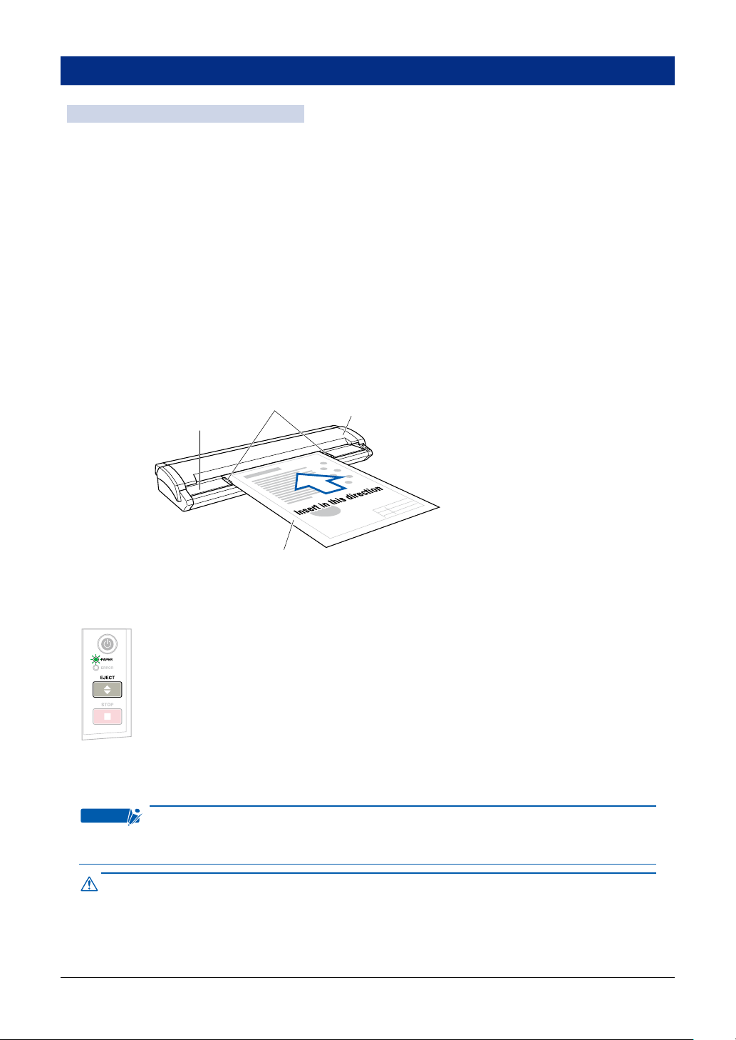
Insert the document (the surface to be scanned) face up into the scanner until the top edge of the
document contacts the feed rollers. At this time, make sure that the document is straight and that it is
centered in the scanner.
(1) With the top cover in the closed status, turn on the scanner’s power supply.
(2) The document guides are attached to the document-scanning table via magnets. Place them at
the edges of the document in alignment with the document width.
(3) Place the document between the document guides, and then inser t the document into the gap
between the top cover and the document-scanning table, making sure that it is straight.
(4) When the preset delay time specied in the driver software has elapsed, the rollers start turning
to automatically feed the document to the position to start scanning. The document is now loaded.
(Manual loading: OFF)
(5) Remove the document guides after you have loaded the document in order to ensure that the
document does not get damaged if it is fed at an angle.
Remove the document guides after the document has been loaded correctly. If the document
guides are not removed, the document might get damaged when it s being fed.
• The delay time (automatic feed time) after the scanner has been turned on is set to three
There are two document setting modes available.
(For more information, refer to "Section 3 Scanning Settings" of the "Scanning Master Pro
Color ‘OPS115’" Instructions Manual (PDF))
• The rollers start turning at a preset delay time after the document has been inserted
so that they automatically feed the document to the position to start scanning. (Manual
loading: OFF)
• The rollers start turning when the [EJECT] key on the control panel is pressed after a
document is inserted so that they automatically feed the document to the position to start
scanning. (Manual loading: ON)
If you want to reload the document, press the [EJECT] key to eject the document. Reload
the ejected document.
When the document has been loaded, the [PAPER] LED (green) lights.
If the PAPER LED does not light after the document feed operation has stopped, press
the EJECT key, and the document gets reset without being ejected and the PAPER LED
lights.
• If the document is inserted at an angle, the image may be scanned in at an angle or a
scanning error may occur. Make sure that the document is aligned with the document
guides when it is inser ted.
seconds.
3-3
Page 54

3-4
• Load the document in the scanner with the surface to be scanned face up.
• Do not place anything other than the document to be scanned on the documentscanning
table. If you do so, the scanner rollers may start rotating, which is extremely dangerous.
• The document may not be fed in correctly if it is curled. The carrier sheet should be used
for curled documents (see Section 3.5, “Using the Carrier Sheet” for details).
• Load the document in the center of the scanner, as the document may be fed in at an
angle and not scanned correctly if it is signicantly off-center.
• Load the document in the center of the scanner. If it is signicantly off- center, the
document may shift and may not be scanned correctly.
Page 55

3.3
“Scan” screen
Slider position
(1) (2) (3) (4) (5) (6) (7) (8)
Handling Documents According to their Material and Thickness
The following problems may occur, depending on the thickness and sur face condition of the document
being scanned.
• The document cannot be loaded.
• Scanning of the document stops half-way through.
• The document slips (resulting in displaced images).
• The end of the document is not scanned.
Such problems may be avoided by taking the following corrective measures.
<Adjust the scanning speed>
Adjust the scan speed using the table below as a guide and following the steps.
(1) Start up the “Scanning Master Pro Color (OPS115)” software that is provided with your scanner,
and then display the [Scan] screen.
(2) Select the [Document] tab to conrm the set "Resolution (DPI)."
(3) Next, select the [Options] tab, and then move the “Scan Speed” slider to the conrmed resolution
position.
"Scan Speed" settings guide (set in the "Scanning Master Pro Color ‘OPS115’")
Note: When “Quality” is set to “High quality” and “Output” is set to “Grayscale” in "Scanning Master
Pro Color ‘OPS115’"
These values are suggested as a guideline only. The actual values will vary according to the
type of document and its condition.
Model Document
Thickness
(mm)
CSX510-09 0.65 to 0.8
0.8 to 1.6
CSX530-09 0.65 to 0.8
0.8 to 1.6
CSX550-09 0.65 to 0.8
0.8 to 1.6
200 300 400 600 800 1200
Position of the
below gure (2)
Position of the
below gure (4)
Position of the
below gure (5)
Position of the
below gure (7)
Position of the
below gure (6)
Position of the
below gure (8)
Position of the
below gure (1)
(Standard)
Position of the
below gure (3)
Position of the
below gure (5)
Position of the
below gure (6)
Position of the
below gure (6)
Position of the
below gure (8)
Resolution (dpi)
Position of the
below gure (1)
(Standard)
Position of the
below gure (4)
Position of the
below gure (4)
Position of the
below gure (6)
Position of the
below gure (6)
Position of the
below gure (8)
Position of the
below gure (1)
(Standard)
Position of the
below gure (1)
(Standard)
Position of the
below gure (5)
Position of the
below gure (5)
Position of the
below gure (5)
Position of the
below gure (8)
Position of the
below gure (1)
(Standard)
Position of the
below gure (1)
(Standard)
Position of the
below gure (1)
(Standard)
Position of the
below gure (6)
Position of the
below gure (1)
(Standard)
Position of the
below gure (1)
(Standard)
Position of the
below gure (1)
(Standard)
Position of the
below gure (1)
(Standard)
Position of the
below gure (1)
(Standard)
Position of the
below gure (1)
(Standard)
Position of the
below gure (1)
(Standard)
Position of the
below gure (1)
(Standard)
3-5
Page 56

3-6
TI P
Refer to the examples below regarding the “Scan speed” slider position in "Scanning
(1)
(Standard)
(4)
(4th from the left)
(5)
(5th from the left)
(6)
(6th from the left)
Master Pro Color ‘OPS115.’"
<Lower the scanning speed>
(1) Start up the “Scanning Master Pro Color (OPS115)” software that is provided with your scanner,
and then display the [Scan] screen.
(2) Select the [Options] tab, and then move the “Scan Speed” slider to the Low end of the scale.
<Support the document at the front and the back of the scanner>
Place tables or similar objects in front of and behind the scanner to support the document while it is
being fed.
Page 57

3.4 Distance Correction
Corrections to the distance can be achieved using the driver software. The driver software included
with your scanner (“Scanning Master Pro Color”) enables you to perform distance correction from the
menu Tool → Adjust Scanner in order to adjust the scanning accuracy.
The adjustment function must be set up when a scanned drawing needs to approximate the accuracy
of the original drawing closely. (This is for making ne adjustments to the accuracy of the scanned
drawing to suit the quality of the paper being used.) It is not normally necessary to perform this
adjustment.
Adjustment method
Perform the distance correction process according to the type of document to be scanned.
Distance correction can be set in a range of ±1%, which remains effective until the scanner’s power is
turned off.
The practice of distance correction necessitates that you measure a vertical line drawn on the
document before following the procedure described below.
(1) Choose a document that has one or more vertical lines drawn on it and scan it at a resolution of
600 dpi (Portrait (vertical) format).
(2) Measure the length of the vertical line of the document and classify it as x (distance on the
document).
(3) Measure the length of the same vertical line in the image data using the command to measure the
distance between two specied points of relative measurement, and classify it as y (distance after
the scan has taken place).
(4) Click on the Distance Correction button in the Adjust Scanner window to open the Distance
Correction window.
(5) Enter the value “x” (distance on the document) and the value “y” (distance after the scan has taken
place) in this window. The values entered here must be within the range of the distance correction.
(6) Click the OK button to calculate the correction value. The distance will be corrected the next time
a document is scanned.
3-7
Page 58

3.5 Using the Carrier Sheet
Transparent sheet (top surface)
Target document
(the surface to be scanned faces up)
White surface
(background surface)
Checkpoint
Use the carrier sheet according to the condition of the document to be scanned.
In the case of scanning the following types of media, always place the document in the carrier sheet
before loading it into the scanner.
• To scan a document that is smaller than Letter size or a document of non-standard size
• To scan a document that is as limp as or limper than a newspaper
• To scan a document that tears or becomes damaged easily
• To scan a document that is considerably damaged
• To scan a document that is badly creased
• To scan a curled document
• To scan a transparent or translucent document
• To scan a document to which other pieces of paper have been attached
• When the target document cannot be properly advanced to the initial position of scanning (because
the target document is not at, or otherwise hard to load in the scanner)
As shown in the gure below, place the document in the carrier sheet with the document’s surface to
be scanned face up (against the transparent top sheet). For scanning, load the carrier sheet into the
scanner with the document’s target sur face (the transparent top sheet) face up.
• When handling the carrier sheet, be ver y careful not to scratch or otherwise damage it.
• If you use the carrier sheet when scanning color documents, the colors may shift slightly
in some cases.
• In the case of CSX510-09 the carrier sheet is an optional item.
3-8
Page 59

CHAPTER 4 DAILY MAINTENANCE
Checkpoint
Caution
4.1 Opening and Closing the Top Cover
Opening the top cover
(1) Turn off the scanner.
(2) Using both hands, push up the left and right open levers on the top cover to unlock them. While
still holding on to the levers, open the cover fully (approximately 47 degrees).
(3) When the top cover is fully open, the xing stay operates to hold the top cover in place.
Closing the top cover
(1) Press the open cover down gently with both hands to close it.
(2) Check that the left and right open levers are locked into position.
If the levers are not locked correctly, the ERROR LED ashes and a scanning operation
cannot be performed.
• Take care not to get your ngers caught when opening or closing the cover.
• When closing the top cover, please be careful not to pinch the document guides.
4-1
Page 60

4-2
4.2 Cleaning the Feed Rollers
Feed rollers
Caution
(1) Turn off the scanner.
(2) Open the top cover as described in Section 4.1, “Opening and Closing the Top Cover”.
(3) While rotating the feed rollers manually, wipe them clean using a soft cloth that has been
moistened with water or a neutral detergent (diluted with water) and rmly wrung out.
(4) Wipe the feed rollers once again using a soft, dry cloth to remove all the moisture.
(5) Close the top cover as described in Section 4.1, “Opening and Closing the Top Cover”.
• Take care not to get your ngers caught in the top cover.
• Only perform this action when the scanner is turned off.
• Please refrain from inserting cloth, etc. into the openings.
Page 61

4.3 Cleaning the Document support Rollers
Document support rollers
Caution
(1) Turn off the scanner.
(2) Open the top cover as described in Section 4.1, “Opening and Closing the Top Cover”.
(3) While rotating the document support rollers manually, wipe them clean using a soft cloth that has
been moistened with water or a neutral detergent (diluted with water) and rmly wrung out.
(4) Wipe the document support rollers once again using a soft, dry cloth to remove all the moisture.
(5) Close the top cover as described in Section 4.1, “Opening and Closing the Top Cover”.
• Take care not to get your ngers caught in the top cover.
• Scanning may be af fected if the document support rollers becomes scratched or dir ty.
• Only perform this action when the scanner is turned off.
• Please refrain from inserting cloth, etc. into the openings.
4-3
Page 62

4-4
4.4 Cleaning the Gap Rollers
Gap rollers
Caution
(1) Turn off the scanner.
(2) Open the top cover as described in Section 4.1, “Opening and Closing the Top Cover”.
(3) While rotating the gap rollers manually, wipe them clean using a soft cloth that has been
moistened with water or a neutral detergent (diluted with water) and rmly wrung out.
(4) Wipe the gap rollers once again using a soft, dry cloth to remove all the moisture.
(5) Close the top cover as described in Section 4.1, “Opening and Closing the Top Cover”.
• Take care not to get your ngers caught in the top cover.
• Only perform this action when the scanner is turned off.
• Please refrain from inserting cloth, etc. into the openings.
Page 63

4.5 Cleaning the Push Rollers
Push rollers
Caution
(1) Turn off the scanner.
(2) Open the top cover as described in Section 4.1, “Opening and Closing the Top Cover”.
(3) While rotating the push rollers manually, wipe them clean using a soft cloth that has been
moistened with water or a neutral detergent (diluted with water) and rmly wrung out.
(4) Wipe the push rollers once again using a soft, dry cloth to remove all the moisture.
(5) Close the top cover as described in Section 4.1, “Opening and Closing the Top Cover”.
• Take care not to get your ngers caught in the top cover.
• Only perform this action when the scanner is turned off.
• Please refrain from inserting cloth, etc. into the openings.
4-5
Page 64

4-6
4.6 Cleaning the Image Sensors (Transparent Contact Plates)
Transparent contact plates
Caution
The scanner’s image quality drops when the transparent contact plates over the image sensors
become dirty, so clean the image sensors whenever necessary.
(1) Turn off the scanner.
(2) Open the top cover as described in Section 4.1, “Opening and Closing the Top Cover”.
(3) As shown below, wipe off any soiled areas on the transparent contact plates using a soft cloth that
has been moistened with water or a neutral detergent (diluted with water) and rmly wrung out.
(4) Wipe the transparent contact plates once again using a soft, dry cloth to remove all the moisture.
(5) Close the top cover as described in Section 4.1, “Opening and Closing the Top Cover”.
• Take care not to get your ngers caught in the cover.
• Do not use a commercial cleaner for ofce equipment, a glass cleaner, or chemical
solvents such as solutions containing alcohol. Moreover, although the transparent
contact plate is not a maintenance part that requires periodic replacement, it is a
consumable part because its sur face may receive slight scratches due to minute
particles of dust and other foreign matter. If document scanning produces unsatisfactory
results (unexpected white or black streaks in the data) due to scratches on the
transparent contact plate or other reasons, please per form the calibration procedure
(see Section 4.7, “ Scanner Calibration”). If the scanning results do not improve after
calibration, the transparent contact plate(s) will need to be replaced.
Page 65

4.7 Cleaning the Sensors
Document size
detection sensors
Paper sensors
Caution
Checkpoint
Accumulated dust on the paper sensors or on the document size detection sensors may prevent the
document from being scanned correctly. The sensors must be cleaned when necessary.
(1) Turn off the scanner.
(2) Open the top cover as described in Section 4.1, “Opening and Closing the Top Cover”.
(3) Wipe the two paper sensors or the ve document size detection sensors using a cotton swab.
(4) Close the top cover as described in Section 4.1 “Opening and Closing the Top Cover”.
• Take care not to get your ngers caught in the top cover.
• Use a cotton swab or something equally soft to gently wipe the paper sensors or on the
document size detection sensors. Do not use any chemicals to clean the sensors.
Document size detection sensors are not equipped to CSX510-09.
4-7
Page 66

4-8
4.8 Removing a Jammed Document
Caution
If a document becomes jammed in the scanner during scanning or another operation, follow the
procedure described below to remove the jammed document.
(1) Turn off the scanner.
(2) Open the top cover as described in Section 4.1 “Opening and Closing the Top Cover”.
(3) If the document is jammed at the front, remove the document by pulling it forward.
(4) If the document is jammed at the rear, remove it by pulling it out from the rear of the scanner.
(5) Close the top cover as described in Section 4.1, “Opening and Closing the Top Cover”.
• Take care not to get your ngers caught in the top cover.
• When removing a jammed document, pull on it gently to prevent damage to the
document.
Page 67

4.9 Scanner Adjustment
Checkpoint
The driver software "Scanning Master Pro Color" (OPS115) is used to adjust (calibrate) the scanner.
Calibration is done when the scanning quality has deteriorated such as in the following cases.
• The scanned image data is distorted
• The scanned image data colors are not uniform
Note: Problems with paper quality such as crease, wrinkles, and bending are excluded from this.
Preparation and checks
Recommended usage environment
Monitor: 1024 x 768 pixels, High Color or better resolution
A low-resolution monitor will make it difcult to discern any problem areas.
Launching the Scanner Adjustment Program
(1) Connect the scanner to the computer, switch on the scanner, and then switch on the computer.
(2) Install Scanning Master Pro Color (OPS115) if it is not already installed.
(3) Click the Start button, then select Programs > Scanning Master Pro Color > Scanner Adjustment.
(4) Click Scanner Adjustment to launch the Scanner Adjustment program.
(5) Select the desired adjustment item from the Scanner menu.
4-9
Page 68
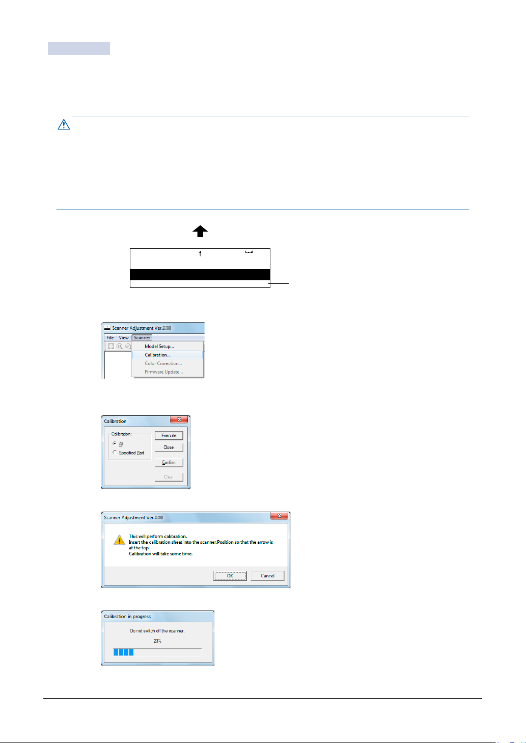
4-10
Calibration
Caution
Scanner
Insertion direction
640650790
250209
Calibration Sheet
Before beginning calibration, clean the transparent contact plates located inside the scanner and the
surface of the document-scanning table. Any dust or dirt on these surfaces may affect the calibration
results and the resulting image quality.
Check that the calibration sheet is free of any dust or dirt.
• The calibration procedure will take some time. Do not turn off the scanner while
calibration is underway. Accidentally turning off the scanner may result in damage that
requires servicing.
• Handle the calibration sheet with care so that it does not get bent. To prevent soiling,
store it in its special storage box.
• The calibration sheet is a consumable item. It cannot be used if it is bent or soiled.
• The calibration sheet is a paper product . Do not attempt to clean it with any type of liquid
cleaner.
(1) Launch the Scanner Adjustment program (as described earlier), and then display the Scanner
menu.
Select Calibration on the Scanner menu.
(2) Select All in Calibration and click the [Execute] button.
(3) The following prompt is displayed. Insert the calibration sheet into the scanner as instructed.
(4) Click the [OK] button to begin calibration.
Page 69

(5) Calibration ends after approximately 10 minutes. (The calibration time depends on the model.)
Caution
Click the [OK] button to complete calibration.
(6) To check the calibration results, click the [Conrm] button in the Calibration screen (shown in step
(2) above).
(7) The following prompt is displayed. Insert the calibration sheet into the scanner once again as
instructed.
(8) Click the [OK] button to start scanning.
The scanned data is displayed when scanning is complete. Colors may differ slightly for individual
sensors to make it easier to identify problem areas in calibration. This does not indicate a defect.
Check that there are no vertical streaks, such as white patches, in the scanned data. (Streaks
occur when calibration is not performed correctly due to contamination by dust or dirt.)
(9) If the data is normal, calibration is complete. Click the [Close] button and exit the Scanner
Adjustment Program.
(10) If any abnormal data is observed, specify the problem areas as follows:
Select Calibration from the Scanner menu, and then select Specied Part in the Calibration screen.
(11) The mouse arrow cursor changes to a cross cursor when moved over the data.
Click the left mouse button with the mouse positioned over the streak data. The selected area is
shown in blue. Repeat this procedure for any additional streaks.
Areas that have been selected (shown in blue) can be deselected by clicking the left mouse button
again.
To deselect all selected areas, click the [Clear] button.
(12) Once all the required areas have been specied, remove the calibration sheet and clean the
transparent contact plate and document-scanning table surfaces. Check the calibration sheet for
dust and dirt.
(13) Click the [Execute] button and then follow the instructions displayed on the screen.The procedure
will be the same as that described in Steps (3) to (5) above. (The time required for calibration will
vary according to the number of repeats specied.)
(14) Perform Steps (8) to (10) once more, and verify the calibration results.
If you perform the calibration procedure several times with no discernible results, there
may be a problem with the scanner itself. In this case, please contact the store where
you purchased your scanner or your nearest Graphtec representative.
4-11
Page 70

CHAPTER 5 TROUBLESHOOTING PROCEDURES
If the scanner seems to be operating abnormally, perform the troubleshooting procedures described in
this chapter before requesting a service call.
5.1 The scanner Is turned on but doesn’t operate at all
Cause Remedy
The power cable has come loose. Insert the power plug rmly.
The scanner is connected to a power
outlet that does not provide the rated
power supply or supply voltage.
The power outlet is not supplying a
supply voltage.
5.2
The scanner operates improperly after connection to the computer
Cause Remedy
Is the scanner properly grounded? Make sure that the scanner is grounded.
Is the USB cable between the computer
and the scanner working properly?
Are you using an USB cable not
compliant with the USB 2.0 interface?
Is an add-on USB card being used? USB 2.0 add-on cards are not supported. Correct
Is the Graphtec Network Utility
connected?
(when using the Ethernet connection)
Use only the rated power supply and supply
voltage.
Check the power supply.
Determine whether there are any problems with
either of the cable connectors (e.g. a broken or bent
pin) and ensure that the cable is inser ted rmly into
the connectors.
Ensure that you use a USB 2.0 -compliant USB
cable.
operation is not guaranteed when the scanner is
connected to a USB port that is not the standard
built-in computer port.
Connect the Graphtec Network Utility.
“Communication error” is displayed for the Graphtec Network Utility status, and connection
cannot be performed.
Cause Remedy
An abnormality has occurred in the
network environment.
The scanner was turned on before
power was supplied to the hub. (With
some hub connections, the scanner is
not recognized if power is supplied to
the hub after it has been supplied to the
scanner.)
The scanner is in energy-saving mode. The Ethernet interface sleeps while the scanner is
Return the network environment to its normal
status.
Turn off the scanner, wait for a short time, and then
turn it on again.
in energy-saving mode. Press one of the buttons
on the scanner’s control panel to bring the scanner
out of the energy-saving mode.
5-1
Page 71

5-2
5.3 The control panel’s red ERROR LED is lit
Cause Remedy
A ROM, RAM or other hardware error
occurred during the scanner’s self-test.
Remedy An internal error has occurred. Contact
the store where you purchased your scanner or
your nearest Graphtec representative.
5.4 The control panel’s red ERROR LED is ashing
Cause Remedy
The scanner was turned on with a
document left loaded inside it.
The top cover was opened during a
scanning operation or while a document
was left in the scanner.
If the document is jammed. Open the cover and remove the document (see
The length of the actual document is
longer than the document length setting
made in the Scanning Arts SP driver.
The top cover is not fully locked. Close the top cover rmly until it is locked in place
Open the cover and remove the document (see
Section 4.8, “Removing a Jammed Document”).
Press the control panel’s [STOP] button to cancel
the error state. Next, remove the document by
pressing the [EJECT] button to feed the document.
Section 4.8, “Removing a Jammed Document).”
The scanner’s ERROR LED ashes when the
end of the document is reached, but this does not
indicate a problem with the scanner itself. Follow
the instructions provided by the driver.
(see Section 4.1, “Opening and Closing the Top
Cover”).
5.5
The document isn’t properly fed to the initial scanning position
Cause Remedy
The document is curled, too thin, or
otherwise in a poor condition.
Dust has accumulated on the paper
sensors.
The document to be scanned may be too
thick or heavy.
The document is a thick, long-length
document.
5.6
The scanned image data is completely white or completely black
Cause Remedy
The document was loaded with its target
surface face down instead of up.
The scanning conditions set were
inappropriate for the document.
Load the document after placing it inside the carrier
sheet (see Section 3.5, “Using the Carrier Sheet”).
Clean the paper sensors (see Section 4.7, “Cleaning
the Sensors”).
The cause of this problem is often attributable
to the weight or length of the document. In such
cases, you should support the document with your
hands when you insert it into the scanner, or lower
the scan speed. If again the result is unsatisfactory,
carry out these two actions simultaneously.
Load the document while supporting it with your
hands.
Load the document in the scanner with its target
surface (the surface to be scanned) face up.
Conrm the scanning conditions and re-set them.
Page 72

5.7 The image quality has dropped
Checkpoint
Original
document
Data is
overlapped
Overlapped data Missing data
Deviation due to scanner specifications
Original
document
Data is
missing
Original
document
Deviation caused
by the specifications
Sensor 1
Joint between
sensors 1 and 2
Joint between
sensors 2 and 3
Joint between
sensors 3 and 4
Joint between
sensors 4 and 5
Sensor 2
Sensor 3
Document feed direction
Sensor 4
Sensor 5
A2 8.5 8.5 A2
Image sensor position Control panel side
Markings on the
document-scanning table
Caution
Cause Remedy
The transparent contact plates over the
image sensors are dirty.
The document is transparent or
translucent, but a carrier sheet was not
Clean the transparent contact plates (see Section
4.6, “Cleaning the Image Sensors”).
Use the carrier sheet (see Section 3.5, “Using the
Carrier Sheet”).
used.
5.8 The scanned data is incorrectly aligned
Cause Remedy
The data is misaligned at a joint between
the image sensors (see the gure
below).
Your scanner comes shipped from the factor y after being adjusted to ensure high
precision. Cause The data is misaligned at a joint between the image sensors (see the
gure below). Remedy After opening the Tools menu of the driver program (Scanning
Master Pro Color driver) provided with y
Due to its operating environment or other factors, however, the scanning precision
may deviate in very rare cases. Moreover, ne adjustment to correct any deviation can
be per formed using the driver software if the cause of the deviation is overlapped or
missing data. Deviations due to the scanner specications, however, cannot be adjusted.
Remedy After opening the Tools menu of the
driver program (Scanning Master Pro Color
driver) provided with your canner, select the Joint
Adjustment function then perform adjustment to
achieve a seamless image.
Because the document is loaded face up, Sensor 1 is the leftmost sensor in the driver
software’s display screens.
5-3
Page 73

5- 4
5.9
Smudges not appearing in the original document appear in the scanned data
Cause Remedy
The image scanned has a glossy
surface, such as a photograph.
Remedy Documents with a glossy surface should
be scanned by placing them inside the carrier
sheet.
5.10 The color intensity of the image data differs
Cause Remedy
The scanner contains ve contact image
sensors, the characteristics of which
have been adjusted. However, some
variation in color intensity may occur,
depending on the type of document
scanned.
The document scanned was creased or
curled.
Adjust the color using the color-correction function
in the driver software (Scanning Master Pro Color)
provided with your scanner. One adjustment
method is to make similar colors all the same color.
Creased or curled documents should be scanned
by placing them inside the carrier sheet.
5.11
5.12
The document length differs from the scanned data length
Cause Remedy
Distance correction adjustments have
been made to ensure scanning precision
for a document of a different paper type.
The scanning precision varies according
to the type of document.
Remedy After opening the Tools menu of the driver
program (Scanning Master Pro Color) provided
with your scanner, select the Distance Correction
function to adjust the precision.
Stripes or moire patterns which are not in the original document appear in the scanned data
Cause Remedy
The scanned document contains lled or
shaded areas.
Remedy Depending on the resolution selected,
data that is comprised of lled or shaded areas may
be scanned in as stripes or moiré patterns. This is
not due to a scanner malfunction.
Note, however, that the vividness of the stripe and
moiré patterns can be lessened by changing the
resolution.
Page 74

5.13 The scanned image data is distorted
Cause Remedy
The scanner’s image scanning quality
has deteriorated.
Is the scanner properly grounded? Make sure that the scanner is grounded.n.
Perform calibration (see Section 4.9, “Scanner
Adjustment”).
5.14 The scanned image data is patchy
Cause Remedy
The scanner’s image scanning quality
has deteriorated.
You are using a carrier sheet with a color
document.
Perform calibration (see Section 4.9, “Scanner
Adjustment”).
Don’t use the carrier sheet with color documents.
5.15 The document cannot be fed correctly
Cause Remedy
The document is fed at an irregular rate
(resulting in the images being scanned
unevenly) or stops feeding half-way
through.
The document has been loaded at an
angle.
The cause of this problem is often attributable
to the weight or length of the document. In such
cases, you should support the document with your
hands when you insert it into the scanner, lower the
scanning speed, or do both.
Reload the document.
5.16 Automatic Deskew is not performed correctly
Cause Remedy
Translucent paper (Mylar paper, tracing
paper, etc.) or paper with damaged
edges is used.
Carrier sheet is used. Do not use a carrier sheet.
In automatic deskew "the tip of the paper" is
detected, and the correction angle is calculated.
If "the tip of the paper" can not be detected properly
because of the paper, automatic deskew might not
be able to give the expected results.
In that case, use the included driver software
(Scanning Master Pro Color)’s “Tools / Deskew”
after scanning and carry out manual deskewing.
5-5
Page 75

APPENDIX
Appendix A Options and Consumables
Optional and consumable items can be obtained from the store where you purchased your scanner or
your nearest Graphtec representative.
Options
Part no. Item name
ST0074 Stand
Consumables
Part no. Item name
IS0922 Carrier sheet (A0)
IS0908 Carrier sheet (A1)
IS0932 Calibration sheet
EM-CP Cleaning paper (50 sheets)
A-1
Page 76

A-2
Appendix B Specications
Item CSX510-09
Document size ANSI Architectural E to A, ANSI Engineering E to A
Maximum width: 965 mm; minimum width: 257 mm
Effective scanning area Width: 932.2 mm (centered)
Length: 999.99999m*1 (
Guaranteed scanning precision range *2841 x 1189 mm
Document thickness Up to 1.6 mm (including the carrier sheet)
Optical resolution 600 dpi
Interpolated resolution 50 dpi up to 4800 dpi (in increments of 1 dpi)
Main scanning system Contact image system (ve A4 sensors in a zigzag pattern)
Sub scanning system Document travel (sheet through) system
Scanning surface Upper surface (Face up)
Scanning speed
Scanning precision
Gradation Monochrome Bilevel, intermediate tones (dithering, error diffusion)
Color space sRGB, Adobe RGB
Sensor Total number of pixels 22,020 pixels
Interface USB 2.0 (High-speed)
Output Image data
Rated power supply 100 to 120/200 to 240 VAC ±10%, 50/60 Hz
Operating environment Temperature: 10˚C to 35˚C
Power consumption 42 W *4 (3 W or less in power-saving mode)
External dimensions (approx.) 1097 (W) x 160 (H) x 322 (D) mm
Weight Approx. 25 kg
*1 In actual scanning of the document is limited by the available memory and hard disk capacity of the computer,
and document condition. Moreover, the scanning of the long-length is out of the guarantee. The skew might be
generated by the setting and the condition of the document, and in this case there is a possibility to be able to
hurt the document, and not be able to scan. In this case it becomes out of the guarantee, please be carefully
for the handling and the setting of the document.
*2 Notes on scanning precision The scanning precision may vary slightly depending on the grade and thickness
of the medium being scanned, and on the operating conditions. The precision gures above were measured
under the operating conditions described below.
• Special test chart: Mylar sheet #300
• Guaranteed precision conditions: Temperature: 20˚C ±3˚C; Humidity: 60% ±10% RH
• Scanning condition: 600dpi High quality (Grayscale)
*3 Including data-transfer time The following system was used to measure the scanning speeds.
• CPU: Core 2 Duo, 2.5 GHz • Memory: 4 GB • Interface: USB 2.0
The scanning speeds may be slower depending on the PC environment or the scanning conditions.
*4 Average power consumption for operating.
*3
*2
Gray scale 256 shades
Gray balance 256 shades
Color 24-bit, 8-bit
Output Color: 48 bits/pixel, Grayscale: 16 bits/pixel
Light source LED (RGB)
400 dpi, ISO A0 size
High-speed scan
• Monochrome: 16 s
• Grayscale: 16 s
• 24-bit color: 44 s
±0.1% or ±1 pixel, whichever is larger
Humidity: 35% to 80% RH (non-condensing)
The value range where scanning length in software
Normal scan
• Monochrome: 30 s
• Grayscale: 30 s
• 24-bit color: 85 s
High quality scan
• Monochrome: 31 s
• Grayscale: 31 s
• 24-bit color: 86 s
)
Page 77

Item CSX530-09
Document size ANSI Architectural E to A, ANSI Engineering E to A
Maximum width: 965 mm; minimum width: 257 mm
Effective scanning area Width: 932.2 mm (centered)
Length: 999.99999m*1 (
The value range where scanning length in software
Guaranteed scanning precision range *2841 x 1189 mm
Document thickness Up to 1.6 mm (including the carrier sheet)
Optical resolution 600 dpi
Interpolated resolution 50 dpi up to 9600 dpi (in increments of 1 dpi)
Main scanning system Contact image system (ve A4 sensors in a zigzag pattern)
Sub scanning system Document travel (sheet through) system
Scanning surface Upper surface (Face up)
Scanning speed
Scanning precision
*3
*2
400 dpi, ISO A0 size
High-speed scan
• Monochrome: 7 s
• Grayscale: 7 s
• 24-bit color: 17 s
Normal scan
• Monochrome: 12 s
• Grayscale: 12 s
• 24-bit color: 31 s
±0.1% or ±1 pixel, whichever is larger
High quality scan
• Monochrome: 13 s
• Grayscale: 13 s
• 24-bit color: 32 s
Gradation Monochrome Bilevel, intermediate tones (dithering, error diffusion)
Gray scale 256 shades
Gray balance 256 shades
Color 24-bit, 8-bit
Color space sRGB, Adobe RGB
Sensor Total number of pixels 22,020 pixels
Output Color: 48 bits/pixel, Grayscale: 16 bits/pixel
Light source LED (RGB)
Interface USB 2.0 (High-speed)
Output Image data
Rated power supply 100 to 120/200 to 240 VAC ±10%, 50/60 Hz
Operating environment Temperature: 10˚C to 35˚C
Humidity: 35% to 80% RH (non-condensing)
Power consumption 42 W
*4 (3 W or less in power-saving mode)
External dimensions (approx.) 1097 (W) x 160 (H) x 322 (D) mm
Weight Approx. 25 kg
*1 In actual scanning of the document is limited by the available memory and hard disk capacity of the computer,
and document condition. Moreover, the scanning of the long-length is out of the guarantee. The skew might be
generated by the setting and the condition of the document, and in this case there is a possibility to be able to
hurt the document, and not be able to scan. In this case it becomes out of the guarantee, please be carefully
for the handling and the setting of the document.
*2 Notes on scanning precision The scanning precision may vary slightly depending on the grade and thickness
of the medium being scanned, and on the operating conditions. The precision gures above were measured
under the operating conditions described below.
• Special test chart: Mylar sheet #300
• Guaranteed precision conditions: Temperature: 20˚C ±3˚C; Humidity: 60% ±10% RH
• Scanning condition: 600dpi High quality (Grayscale)
*3 Including data-transfer time The following system was used to measure the scanning speeds.
• CPU: Core 2 Duo, 2.5 GHz • Memory: 4 GB • Interface: USB 2.0
The scanning speeds may be slower depending on the PC environment or the scanning conditions.
*4 Average power consumption for operating.
)
A-3
Page 78

A-4
Item CSX550-09
Document size ANSI Architectural E to A, ANSI Engineering E to A
Maximum width: 965 mm; minimum width: 257 mm
Effective scanning area Width: 932.2 mm (centered)
Length: 999.99999m*1 (
The value range where scanning length in software
Guaranteed scanning precision range *2841 x 1189 mm
Document thickness Up to 1.6 mm (including the carrier sheet)
Optical resolution 1200 dpi
Interpolated resolution 50 dpi up to 9600 dpi (in increments of 1 dpi)
Main scanning system Contact image system (ve A4 sensors in a zigzag pattern)
Sub scanning system Document travel (sheet through) system
Scanning surface Upper surface (Face up)
Scanning speed
Scanning precision
*3
*2
400 dpi, ISO A0 size
High-speed scan
• Monochrome: 7 s
• Grayscale: 7 s
• 24-bit color: 15 s
Normal scan
• Monochrome: 11 s
• Grayscale: 11 s
• 24-bit color: 28 s
±0.1% or ±1 pixel, whichever is larger
High quality scan
• Monochrome: 12 s
• Grayscale: 12 s
• 24-bit color: 29 s
Gradation Monochrome Bilevel, intermediate tones (dithering, error diffusion)
Gray scale 256 shades
Gray balance 256 shades
Color 24-bit, 8-bit
Color space sRGB, Adobe RGB
Sensor Total number of pixels 44,040 pixels
Output Color: 48 bits/pixel, Grayscale: 16 bits/pixel
Light source LED (RGB)
Interface USB 2.0 (High-speed)
Network (10 BASE-T/100 BASE-TX/1000 BASE-T)
Output Image data
Rated power supply 100 to 120/200 to 240 VAC ±10%, 50/60 Hz
Operating environment Temperature: 10˚C to 35˚C
Humidity: 35% to 80% RH (non-condensing)
Power consumption 55 W *4 (3 W or less in power-saving mode)
External dimensions (approx.) 1097 (W) x 160 (H) x 322 (D) mm
Weight Approx. 25 kg
*1 In actual scanning of the document is limited by the available memory and hard disk capacity of the computer,
and document condition. Moreover, the scanning of the long-length is out of the guarantee. The skew might be
generated by the setting and the condition of the document, and in this case there is a possibility to be able to
hurt the document, and not be able to scan. In this case it becomes out of the guarantee, please be carefully
for the handling and the setting of the document.
*2 Notes on scanning precision The scanning precision may vary slightly depending on the grade and thickness
of the medium being scanned, and on the operating conditions. The precision gures above were measured
under the operating conditions described below.
• Special test chart: Mylar sheet #300
• Guaranteed precision conditions: Temperature: 20˚C ±3˚C; Humidity: 60% ±10% RH
• Scanning condition: 600dpi High quality (Grayscale)
*3 Including data-transfer time The following system was used to measure the scanning speeds.
• CPU: Core 2 Duo, 2.5 GHz • Memory: 4 GB • Interface: USB 2.0
The scanning speeds may be slower depending on the PC environment or the scanning conditions.
*4 Average power consumption for operating.
)
Page 79

Appendix C External Dimensions
1070
1097
322
160
● CSX510-09/CSX530-09/CSX550-09
Unit: mm
Dimensional accuracy: ±5 mm
A-5
Page 80

● CSX510-09/CSX530-09/CSX550-09
972
1097 650
717±10
When the scanner is mounted on the stand
Unit: mm
Dimensional accuracy: ±5 mm
A-6
Page 81

INDEX
B
BEFORE USING THE SCANNER . . . . . . . . . .1-1
C
Cable clamp . . . . . . . . . . . . . . . . . . . . . . . 1-1, 1-3
Cable clamp, Attaching and using . . . . . . . . . 1-4
Calibration . . . . . . . . . . . . . . . . . . . . . . . . . . . .4-10
Calibration sheet . . . . . . . . . . . . . . . . . . . . 1-1, A-1
Carrier sheet . . . . . . . . . . . . . . . . . . . . . . . 1-1, A-1
Carrier sheet, Using . . . . . . . . . . . . . . . . . . . . 3-8
Cleaning paper . . . . . . . . . . . . . . . . . . . . . 1-1, A-1
Compatible document types . . . . . . . . . . . . . . 3-1
CONNECTION . . . . . . . . . . . . . . . . . . . . . . . . .2-1
Consumables . . . . . . . . . . . . . . . . . . . . . . . . . A-1
Contents of the Package . . . . . . . . . . . . . . . . . .1-1
Control Panel . . . . . . . . . . . . . . . . . . . . . . . . . . .1-2
Copyright . . . . . . . . . . . . . . . . . . . . . . . . . . . . . . . I
D
DAILY MAINTENANCE . . . . . . . . . . . . . . . . . . 4-1
Device Setup, Settings . . . . . . . . . . . . . . . . . .2-20
Distance correction . . . . . . . . . . . . . . . . . . . . . 3-7
Document, Loading . . . . . . . . . . . . . . . . . . . . . 3-3
Document guides . . . . . . . . . . . . . . . . 1-1, 1-2, 3-3
Document size detection sensors . . . . . . . . . . 4-7
Document suppor t plates . . . . . . . . . . . . . 1-1, 1-3
Document suppor t plates, Attaching . . . . . . . . 1-4
Document suppor t rollers, Cleaning . . . . . . . . 4-3
Document types . . . . . . . . . . . . . . . . . . . . . . . 3-1
Driver software . . . . . . . . . . . . . . . . . . . . . 1-1, 2-7
H
Handling documents according . . . . . . . . . . . . 3- 5
Handling Precautions . . . . . . . . . . . . . . . . . . . . vi
I
Image sensors, Cleaning . . . . . . . . . . . . . . . . 4-6
Installation Precautions . . . . . . . . . . . . . . . . . . . . ii
International ENERGY STAR Program . . . . . . . . I
INTRODUCTION . . . . . . . . . . . . . . . . . . . . . . . . . I
IS0908 . . . . . . . . . . . . . . . . . . . . . . . . . . . . . . . A-1
IS0922 . . . . . . . . . . . . . . . . . . . . . . . . . . . . . . . A-1
IS0932 . . . . . . . . . . . . . . . . . . . . . . . . . . . . . . . A-1
J
Jammed document, Removing . . . . . . . . . . . . 4-8
L
LOADING A DOCUMENT . . . . . . . . . . . . . . . . 3-1
M
Main power switch . . . . . . . . . . . . . . . . . . . 1-3, 2-2
Maintenance and Inspection Precautions . . . . .viii
Manual loading . . . . . . . . . . . . . . . . . . . . . . . . 3-3
N
Network connection . . . . . . . . . . . . . . . . 2- 6, 2-18
Network connector . . . . . . . . . . . . . . . . . . 1-3, 2-6
Network Utility . . . . . . . . . . . . . . . . . . . . . . . . .2-19
Notes on this Manual . . . . . . . . . . . . . . . . . . . . . I
E
EJECT key . . . . . . . . . . . . . . . . . . . . . . . . . . . . .1-2
EM-CP . . . . . . . . . . . . . . . . . . . . . . . . . . . . . . . A-1
ERROR LED . . . . . . . . . . . . . . . . . . . . . . . . . . .1-2
External dimensions . . . . . . . . . . . . . . . . . . . . A-5
F
Feed rollers, Cleaning . . . . . . . . . . . . . . . . . . . 4-2
Front View . . . . . . . . . . . . . . . . . . . . . . . . . . . . .1-2
G
Gap rollers, Cleaning . . . . . . . . . . . . . . . . . . . 4-4
Graphtec Network Utility . . . . . . . . . . . . . . . . .2-22
Graphtec Network Utility, Installing . . . . . . . . .2-22
Graphtec Network Utility, Settings . . . . . . . . .2-24
O
OPS115 . . . . . . . . . . . . . . . . . . . . . . . . . . . . . .2-16
Options . . . . . . . . . . . . . . . . . . . . . . . . . . . . . . A-1
P
PAPER LED . . . . . . . . . . . . . . . . . . . . . . . . . . .1-2
Paper sensors . . . . . . . . . . . . . . . . . . . . . . 1-2, 4-7
Part Names and Functions . . . . . . . . . . . . . . . .1-2
Power-saving mode . . . . . . . . . . . . . . . . . . . . . 2-3
POWER button . . . . . . . . . . . . . . . . . . . . . . . . .1-2
Power cable . . . . . . . . . . . . . . . . . . . . . . . . . . . .1-1
Power inlet . . . . . . . . . . . . . . . . . . . . . . . . . . . . 1-3
Power On and Off . . . . . . . . . . . . . . . . . . . . . . .2-2
Power Supply, Connecting . . . . . . . . . . . . . . . .2-1
Power Supply Precautions . . . . . . . . . . . . . . . . iv
I-1
Page 82

PREPARATIONS . . . . . . . . . . . . . . . . . . . . . . .2-1
Push rollers, Cleaning . . . . . . . . . . . . . . . . . . . 4-5
R
Rear View . . . . . . . . . . . . . . . . . . . . . . . . . . . . 1-3
Registered Trademarks . . . . . . . . . . . . . . . . . . . . I
Reset button . . . . . . . . . . . . . . . . . . . 1-3, 2-6, 2-26
S
Scanner, Assembling . . . . . . . . . . . . . . . . . . . 1- 4
Scanner adjustment . . . . . . . . . . . . . . . . . . . . 4-9
Scanner adjustment program . . . . . . . . . . . . . 4-9
Scanner driver software, Installing . . . . . . . . . .2-7
Scanner to a computer, Connecting . . . . . . . . 2-5
Scanner unit . . . . . . . . . . . . . . . . . . . . . . . . . . .1-1
Scanner warm-up . . . . . . . . . . . . . . . . . . . . . . . . II
Scanning Master Pro Color Application . . . . .2-16
Sensors, Cleaning . . . . . . . . . . . . . . . . . . . . . . 4 -7
Specications . . . . . . . . . . . . . . . . . . . . . . . . . A-2
ST0074 . . . . . . . . . . . . . . . . . . . . . . . . . . . . . . A-1
STOP key . . . . . . . . . . . . . . . . . . . . . . . . . . . . .1-2
System requirements . . . . . . . . . . . . . . . . . . . 2- 4
T
TO ENSURE SAFE AND CORRECT USE . . . . . i
Top cover . . . . . . . . . . . . . . . . . . . . . . . . . . . . . .1-2
Top cover, Opening and Closing . . . . . . . . . . . 4-1
Top cover open levers . . . . . . . . . . . . . . . . . . . .1-2
Transparent contact plates . . . . . . . . . . . . . . . 4-6
TROUBLESHOOTING PROCEDURES . . . . . 5-1
U
Usage precautions . . . . . . . . . . . . . . . . . . . . . . . II
USB cable . . . . . . . . . . . . . . . . . . . . . . . . . . . . .1-1
USB connection . . . . . . . . . . . . . . . . . . . . . . . 2-5
USB connector . . . . . . . . . . . . . . . . . . . . . . . . 1-3
User’s manual . . . . . . . . . . . . . . . . . . . . . . . . . .1-1
I-2
Page 83

The specifications, etc., in this manual are
subject to change without notice.
CSX500- UM-152
June 22, 2011 1st edition
GRAPHTEC CORPORATION
Page 84

640743301
503-10 Shinano-cho, Totsuka-ku,
Yokohama 244-8503, Japan
Tel : +81(045)825-6250
Fax : +81(045)825-6396
Email : info@graphteccorp.com
Web : www.graphteccorp.com
Printed in Japan
 Loading...