

Page 1

SERVICE MANUAL
MANUAL NO. CSX300-UM-251
300-09
CSX300-UM251-05-9370
Page 2

Page 3

HISTORY OF REVISIONS
No. Date issued Description of revision Page Edition
1 08.02.29 First Printing. All 01
2 08.05.28
3 08.08.29 Item No. 2 and No. 3 were swapped. 12-1 03
4 09.02.12
5 09.02.12
6 09.10.08 The part number for the scan glass A was updated. 6-1,12-5 05
7 09.10.08
8 09.10.08 The figure for the press roller was added. 12-7 05
9 09.10.08 The part number for the CIS sensors were updated. 6-1,12-5 05
10 09.10.13
11 09.10.13
12 09.10.13
13 09.10.13
14 09.10.13
15 09.10.13
16 09.10.13
17 09.10.13
18 09.10.13
19 09.10.13 The part number for the
20 09.10.13 The part number for the
21 09.10.13 The part number for the
22 09.10.13 The part number for the
23 09.10.13 The part number for the
24 09.10.13 The part number for the
25 09.10.13 The part number for the
26 09.10.13 The part number for the
27 09.10.13 The part number for the
28 09.10.13 The part number for the
29 09.10.13 The part number for the
30 09.10.13 The part number for the
The IS0925 was assigned to consumable supplies parts.
The part number for the Press Roller A was corrected.
The item number direction for the Press Roller A was corrected.
The part number for the document guard plastic plates were added.
The part number for the SVC_Main_BD_S was corrected.
The part number for the SVC_CIS_BD was corrected..
The part number for the SVC_PWR_BD was corrected..
The part number for the
The part number for the
The part number for the
The part number for the
The part number for the
The part number for the
Right_Side_Cover_A
Feed_Roller_F
Feed_Roller_R
Pinch_Roller_A
Top_Cover
Left_Side_Cover A
Front_Cover_A was corrected. 12-1 05
Press_ A_2 was corrected. 12-6 05
Press_ A_1 was corrected. 12-6 05
Press_ A_3 was corrected. 12-6 05
Harness 2 was corrected. 12-9 05
Harness 11 was corrected. 12-9 05
Harness 12 was corrected. 12-9 05
Harness 15 was corrected. 12-9 05
Harness 17 was corrected. 12-9 05
Harness 19 was corrected. 12-9 05
Harness 21 was corrected. 12-9 05
Harness 22 was corrected. 12-9 05
was corrected.
was corrected.
was corrected.
was corrected.
was corrected.
was corrected.
12-9 02
6-1,12-6 04
12-6 04
12-6 05
6-1 05
6-1,12-3 05
6-1,12-8 05
6-1 05
6-1,12-6 05
6-1,12-6 05
6-1,12-5 05
12-1 05
12-1 05
CSX300-UM-251-9370 i
Page 4

CSX300-UM-251-9370 ii
Page 5

CONTENTS
1. OVERVIEW .......................................................................................................................................1-1
1.1 Standard Specifications .......................................................................................................... 1-1
1.2 External View ...............................................................................................................................1-3
2. PART NAMES AND FUNCTIONS ......................................................................................2-1
2.1 Part Names and Functions .....................................................................................................2-1
3. CONNECTION AND PREPARATIONS .......................................................................... 3-1
3.1 Connecting to the Power Supply .........................................................................................3-1
3.2 Turning the Power On and Off ..............................................................................................3-2
3.3 System Requirements ............................................................................................................. 3-4
3.4 Connecting the Scanner to a Computer .......................................................................... 3-5
4. INSTALLING THE SOFTWARE ......................................................................................... 4-1
4.1 Installing the Driver Software for Windows Vista .........................................................4-1
4.2 Installing the Driver Software for Windows XP ............................................................ 4-4
4.3 Installing the Driver Software for Windows 2000 ........................................................ 4-6
4.6 Checking the Interface Connection for Windows 2000 ...........................................4-10
4.7 Installing the Scanning Master 21+ Application .........................................................4-11
5. DAILY MAINTENANCE ............................................................................................................ 5-1
5.1 Opening and Closing the Top Cover ..................................................................................5-1
5.2 Cleaning the Feed Rollers ......................................................................................................5-2
5.3 Cleaning the Document support Rollers ......................................................................... 5-3
5.4 Cleaning the Gap Rollers ....................................................................................................... 5-4
5.5 Cleaning the Push Rollers ..................................................................................................... 5-5
5.6 Cleaning the Image Sensors (Contact glass plates) .................................................. 5-6
5.7 Cleaning the Media sensors ..................................................................................................5-7
5.8 Removing a Jammed Document ......................................................................................... 5-8
5.9 Scanner Calibration ................................................................................................................. 5-9
6. RECOMMENDED PARTS LIST .......................................................................................... 6-1
7. LIST OF JIGS AND TOOLS ...................................................................................................7-1
7.1 Jigs ................................................................................................................................................... 7-1
7.2 Tools ................................................................................................................................................ 7-1
7.3 Other ................................................................................................................................................ 7-1
8.
DISASSEMBLING AND ADJUSTING THE MECHANICAL PARTS
8.1 Top Cover .......................................................................................................................................8-1
8.2 Front Cover ...................................................................................................................................8-2
8.3 Left Side Cover .......................................................................................................................... 8-3
8.4 Right Side Cover ....................................................................................................................... 8-4
8.5 Front Guide Assembly ............................................................................................................ 8-5
CSX300-UM-251-9370 iii
.......................................... 8-1
Page 6

8.6 Shield Cover ................................................................................................................................ 8-6
8.7 Feed Drive Belt ............................................................................................................................8-7
8.8 Main Board .................................................................................................................................. 8-9
8.9 Board Base Chassis ...............................................................................................................8-10
8.10 CIS Board .................................................................................................................................. 8-11
8.11 CIS Sensor ................................................................................................................................8-12
8.12 Cover Sensor ...........................................................................................................................8-14
8.13 Front Media Sensor ...............................................................................................................8-15
8.14 Rear Media Sensor ................................................................................................................8-16
8.15 Media width sensors .............................................................................................................8-17
8.16 Document Roller Assembly ............................................................................................... 8-18
8.16 Contact Glass Assembly ....................................................................................................8-19
8.17 Pinch Roller ..............................................................................................................................8-21
8.18 Feed Rollers .............................................................................................................................8-22
8.19 CIS Power Board ....................................................................................................................8-24
8.20 Switching Power Supply Board .......................................................................................8-25
8.21 Feed Motor ...............................................................................................................................8-26
9. ADJUSTMENTS USING THE SOFTWARE ................................................................ 9-1
9.1 Starting the Software ................................................................................................................9-1
9.2 Preparations before Making Adjustments ...................................................................... 9-4
9.3 Preparing Adjustment Charts .............................................................................................. 9-5
9.4 Making Adjustments .................................................................................................................9-7
9.4.1 Calibration (white and black correction) .................................................................9-8
9.4.2 Feed distance adjustment .......................................................................................... 9-10
9.4.3 Sensor Stitch Adjustment ........................................................................................... 9-13
9.4.4 Scanning Start Position Adjustment ...................................................................... 9-19
9.5 Downloading Firmware ..........................................................................................................9-24
10. TROUBLESHOOTING ...........................................................................................................10-1
10.1 TROUBLESHOOTING ............................................................................................................10-1
11. OPTION AND CONSUMABLES .....................................................................................11-1
11.1 Optional Item ............................................................................................................................ 11-1
11.2 Consumables ........................................................................................................................... 11-1
12. PARTS LISTS .............................................................................................................................12-1
12.1 Outer Casing ............................................................................................................................ 12-1
12.2 Shield Cover ............................................................................................................................12-2
12.3 Main Frame ...............................................................................................................................12-3
12.4 Top Frame Bottom .................................................................................................................12-5
12.5 Feed Section ............................................................................................................................12-6
12.6 Bottom Chassis ......................................................................................................................12-8
Page 7

12.7 Harness ......................................................................................................................................12-9
12.8 Inlet ..............................................................................................................................................12-9
12.9 Other Parts ...............................................................................................................................12-9
13. BLOCK DIAGRAM AND CIRCUIT DIAGRAMS ...................................................13-1
13.1 Block Diagram .........................................................................................................................13-1
13.2 Circuit Diagrams ....................................................................................................................13-2
13.2.1 Data Controller Board (Main Board) ..................................................................... 13-2
13.2.2 CIS Controller Board ................................................................................................ 13-17
13.2.3 Power Board .................................................................................................................13-20
13.2.4 Control Panel Board, CN5041-06A ...................................................................... 13-22
13.2.5 USB Relay Board, CN5041-07 ................................................................................13-23
CSX300-UM-251-9370 v
Page 8

Page 9

1. OVERVIEW
1. OVERVIEW
1.1 Standard Specifications
Item CSX300-09
Document size ANSI E to ISO A4
Maximum width: 965 mm; minimum width: 257 mm
Effective scanning area Maximum width : 932.2 mm
Maximum length : 16 m
Guaranteed scanning
precision range
*2
841 mm x 1189 mm
Document thickness Up to 0.8 mm (including the carrier sheet)
Optical resolution 600 dpi
Interpolated resolution 100, 200, 300, 400, 600, 800, 1200 dpi
Main scanning system Contact image sensor system (five A4 sensors in a zigzag pattern)
Sub scanning system Document travel (sheet through) system
Scanning speed
*3
400 dpi, ISO A0 size
High-speed scan Normal scan High quality scan
• Monochrome: 8 s • Monochrome: 14 s • Monochrome: 18 s
• Grayscale: 23 s • Grayscale: 26 s • Grayscale: 33 s
• 24-bit color: 62 s • 24-bit color: 75 s • 24-bit color: 100 s
Scanning precision*3 ±0.1% or ±1 pixel, whichever is larger
Gradation Monochrome : Bilevel, intermediate tones (dithering, error diffusion)
Gray scale : 256 shades
Gray balance : 256 shades
Color : 24-bit
Threshold value A DSP (digital signal processor) enables automatic setting of the threshold
value (monochrome scans only)
Color space sRGB compatible
Sensor
Total number of pixels
Output Color: 42 bits/pixel, Grayscale: 14 bits/pixel
22,020 pixels
Light source LED (RGB)
Interface USB 2.0
Output Image data
Rated power supply 100 to 120/200 to 230 VAC ±10%, 50/60 Hz
Operating environment Temperature: 10˚C to 35˚C
Humidity: 35% to 80% RH (non-condensing)
Power consumption 60 W or less (5 W or less in power-saving mode)
External dimensions
1097 (W) x 160 (H) x 332 (D) mm (without stand)
(approx.)
Weight (approx.)
13 kg (without stand)
*1
*1 If the document is a long-length document, the actual length that can be scanned is limited by the available
memory (hard disk or other data storage device) of the computer to which the scanner is connected, and also by
the grade of the medium being scanned.
*2 Notes on scanning precision
The scanning precision may vary slightly depending on the grade and thickness of the medium being scanned,
and on the operating conditions. The precision figures above were measured under the operating conditions
described below.
• Special test chart: Mylar sheet #300
• Guaranteed precision conditions: Temperature: 23°C ±5°C; Humidity: 55% ±15% RH
CSX300-UM-251-9370 1-1
Page 10

*3 Including data-transfer time
The following system was used to measure the scanning speeds.
• CPU: Pentium 4, 3.2 GHz or better • Memory: 1 GB or more • Interface: USB 2.0
The scanning speeds may be slower depending on the PC system used.
1. OVERVIEW
CSX300-UM-251-9370 1-2
Page 11
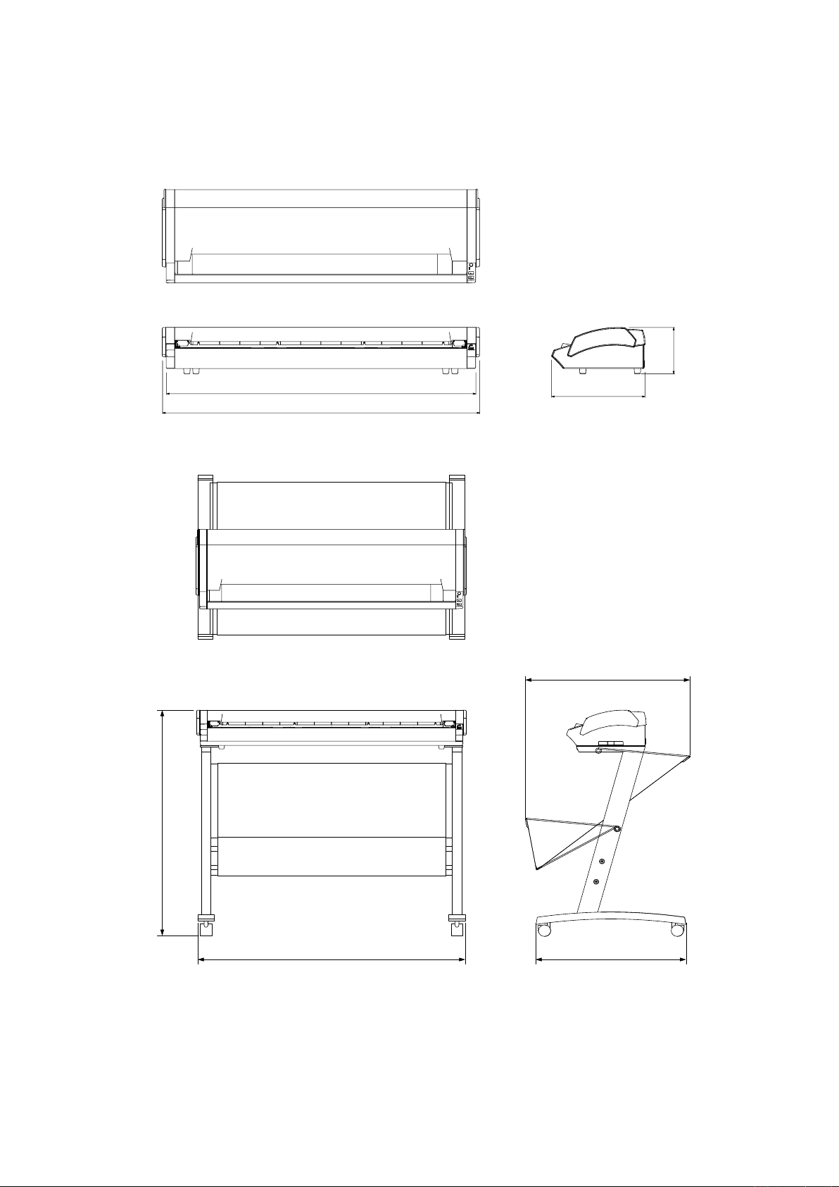
1.2 External View
1070
1097
322
160
972
1097 650
717±10
External Dimensions
1. OVERVIEW
Unit: mm
Dimensional accuracy: ±5 mm
External Dimensions with the option stand
CSX300-UM-251-9370 1-3
Page 12

Page 13
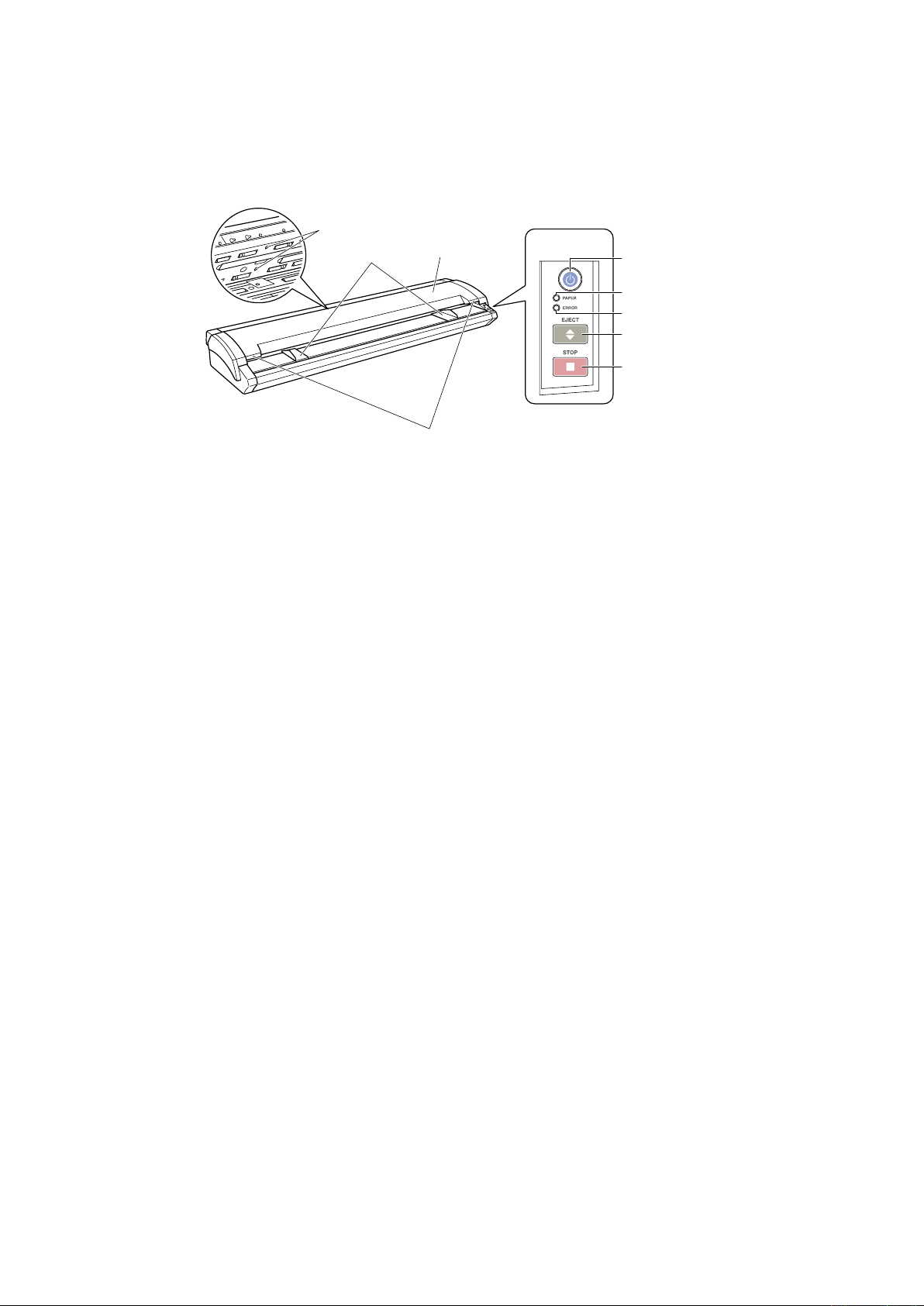
2. PART NAMES AND FUNCTIONS
(1) Top cover
Control Panel
(4) Document guides
(3)
Top cover open levers
(2) Paper sensors
(5) Power button/LED
(6)
PAPER LED
(7) ERROR LED
(8) EJECT key
(9) STOP key
2. PART NAMES AND FUNCTIONS
2.1 Part Names and Functions
Front View/Control Panel
Top cover
(1) Top cover ..............................Open the top cover to clean the document hold-down unit and contact glass
plates.
(2) Media sensors ......................These sense whether a document is present in the scanner.
(3) Top cover open levers ..........Press these levers to open the top cover.
If the top cover is opened during a scanning operation, the operation will be
stopped compulsorily.
(4) Document guides .................Use these guides to determine the position of a document when you load the
document.
Control Panel
(5) Power button/LED (blue) ......Controls the on/off status of the power supply to the scanner.
Lit: The scanner is turned on.
Flashing: Flashes when the scanner is in power-saving mode.
Unlit: The scanner is turned off.
Lit: Lights when the scanner is turned on and remains lit while it is operating
normally.
(6) PAPER LED (green) .............Lit: Lights when a document has been loaded.
Flashing: Flashes while image data is being scanned.
Unlit: Normal status (Local status).
(7) ERROR LED (red) ................Lit: Lights to indicate a hardware error.
Flashing: Flashes when any of the following occurs:
• A document is detected during the self-test when the scanner is turned on
• When a paper jam is detected
• When the top cover is open
• When the document length is shorter than the specified scan length*1
*1 When “Confirm” has been selected for the End-of-paper Processing setting in the driver
software.
Unlit: Normal status
CSX300-UM-251-9370 2-1
Page 14
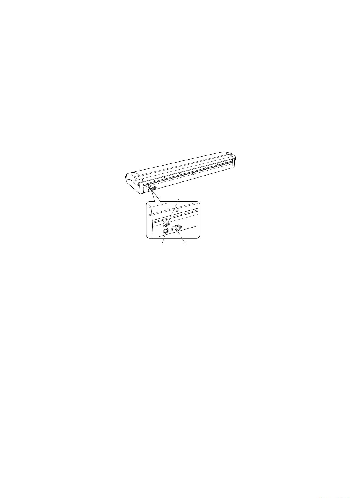
2. PART NAMES AND FUNCTIONS
(10) USB connector
(11) Power inlet
(12) Main power switch
(8) EJECT key ...........................
Press this key to feed the document.
If this key is pressed when the scanner is in document-loaded status, the
document-loaded status is canceled and the document is ejected to the front
of the scanner.
If this key is pressed after the scanning operation has been canceled or
after scanning of the document was halted partway through the scanning
operation, the document-loaded status is canceled and the document is
ejected to the rear of the scanner.
(9) STOP key .............................Compulsorily stops scanning of the document.
If the ERROR LED flashes when the top cover is in the closed status, press
this key to suspend the scanning operation and check whether a paper jam
has occurred.
Rear View
(10) USB connector ...................Used to connect the USB interface cable.
(11) Power inlet ..........................Used to connect the power cable.
(12) Main power switch .............Used to turn the main power supply on or off.
CSX300-UM-251-9370 2-2
Page 15
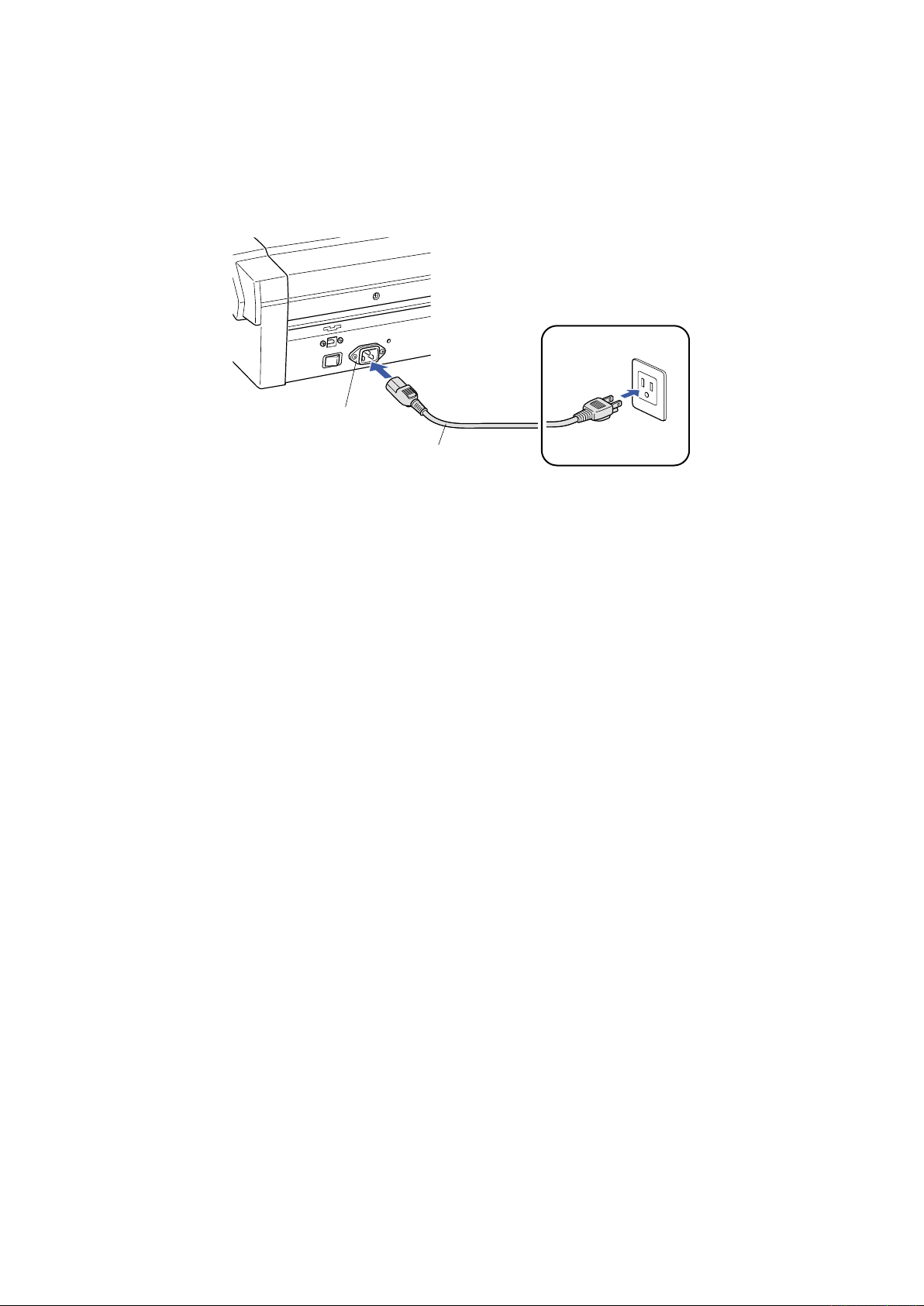
3. CONNECTION AND PREPARATIONS
Power cable
Power inlet
AC power outlet
3. CONNECTION AND PREPARATIONS
3.1 Connecting to the Power Supply
Connect one end of the power cable provided to the scanner’s power inlet and the other end to an AC power
outlet of the rated supply voltage.
CSX300-UM-251-9370 3-1
Page 16

3. CONNECTION AND PREPARATIONS
ON
ON
OFF
Checkpoint
3.2 Turning the Power On and Off
The LED (blue) on the [POWER] button changes as follows to indicate the scanner’s power supply status.
• Unlit: The scanner is turned off.
• Lit: Lights when the scanner is turned on and remains lit while it is operating normally.
• Flashing: Flashes when the scanner is in power-saving mode.
Turning the Power On
(1) Connect the power cable.
(2) Turn on the main power switch (the | side).
Press the [POWER] button on the scanner’s control panel.
When the scanner is in the power-on status, the [POWER] button lights blue.
Turning the Power Off
Press the [POWER] button on the scanner’s control panel.
When the scanner is in the power-off status, the [POWER] button LED is extinguished.
After the scanner has been turned off, wait at least five seconds before turning it on again.
CSX300-UM-251-9370 3-2
Page 17

3. CONNECTION AND PREPARATIONS
To cancel the
powe
r-saving mode
Notes on the power-saving mode
The scanner automatically switches to power-saving mode (the blue LED on the power button flashes) after
approximately 12 minutes have elapsed without a document being loaded in the scanner. To return the
scanner to normal status (Local status), press either the [STOP] or the [EJECT] key.
CSX300-UM-251-9370 3-3
Page 18

3. CONNECTION AND PREPARATIONS
Checkpoint
3.3 System Requirements
The minimum system requirements for running the scanner’s hardware and software are listed below.
• Operating system: Windows 2000 Professional, XP Professional, or XP Home Edition
• CPU: Pentium III, 1 GHz
• Memory: 256 MB or more
• Monitor: 1024 x 768 pixels, True Color or higher
• Disk space: At least 10 GB
• Mouse
• Interface: USB 2.0 interface
*1 When the document length exceeds length of an A0-size document, additional hard disk space is required.
Recommended environment
• CPU: Pentium 4, 2 GHz
• Memory: 1 GB or more
• Disk space: At least 30 GB
• USB 2.0 interface (that comes standard with your computer)
*1
Use with a system configuration below the recommended specifications will affect the scanning speed and prevent
the scanner from operating to its specified capabilities. Moreover, colors may not be displayed correctly if the num-
ber of colors that the monitor can display is 256 or less.
To edit an A1-size or larger grayscale document with a resolution of 400 dpi or higher, or a 24-bit color document,
you may need more than the recommended memory sizes above.
CSX300-UM-251-9370 3-4
Page 19

3. CONNECTION AND PREPARATIONS
Computer
USB inte
rface connector
USB cable
Important
Checkpoint
3.4 Connecting the Scanner to a Computer
USB Connection
A USB cable is used to connect the scanner to the computer, via the respective USB interface connectors.
The connectors at the computer and scanner ends of the USB cable have different shapes. Make sure that
the cable is oriented correctly before making the connection.
Make sure that both the scanner and the computer are in the power-off status when connecting them.
• Make sure that the USB cable is firmly inserted into the interface connectors.
• The operation of the scanner cannot be guaranteed in the following cases:
When the cable is connected to a USB hub or an add-on USB board.
t
When you are using a custom-built computer or one that you have modified.
t
• Do not perform any of the following actions:
Remove or reinsert the cable while you are installing the driver.
t
Remove or reinsert the cable while starting up the computer or the scanner.
t
Remove or reinsert the cable while transferring data.
t
Connect two or more scanners to a single computer.
t
Please see the separate “Quick Start Guide” for the scanner driver installation procedure.
CSX300-UM-251-9370 3-5
Page 20

Page 21

4. INSTALLING THE SOFTWARE
Checkpoint
4. INSTALLING THE SOFTWARE
The procedure outlined below is based on the requirement that you are logged on to Windows with administrator
rights. Consult your Windows manual for more information.
4.1 Installing the Driver Software for Windows Vista
(1) Use the USB cable to connect the scanner to the computer, and then turn on the computer.
(2) When Windows starts up, insert the CD-ROM supplied with the scanner into the CD-ROM drive. The
“Start” screen opens automatically. Click the [Quit] button to close the “Start” screen.
(3) Turn on the power to the scanner.
(4) The screen shown below is displayed. Click "Locate and install driver software (recommended)".
(5) The User Account Control screen is displayed. Click [Continue] to proceed with the installation.
(6) The screen shown below is displayed. Click "Don't search online".
(7) The screen shown below is displayed. Click "I don't have the disc. Show me other options."
CSX300-UM-251-9370 4-1
Page 22

4. INSTALLING THE SOFTWARE
(8) The screen shown below is displayed. Click "Browse my computer for driver software (advanced)".
(9) The screen shown below is displayed. Click [Browse] and either select the [DRIVER] folder in the CD-
ROM drive or enter a CD-ROM drive name and \DRIVER using the keyboard.
Example: For drive E, enter "E:\DRIVER".
(10) Click [Next]. The wizard will start searching for the driver.
(11) The screen shown below is displayed. Click [Install] to proceed with the installation.
CSX300-UM-251-9370 4-2
Page 23

4. INSTALLING THE SOFTWARE
(12) The screen shown below is displayed when the wizard has finished installing the driver.
Click the [Close] button to close the "Found New Hardware" wizard.
(13) The Windows Vista desktop appears, and the scanner is recognized by the computer.
CSX300-UM-251-9370 4-3
Page 24

4. INSTALLING THE SOFTWARE
4.2 Installing the Driver Software for Windows XP
(1) Use the USB cable to connect the scanner to the computer, and then turn on the computer.
(2) When Windows starts up, insert the CD-ROM supplied with the scanner into the CD-ROM drive. The
“Start” screen opens automatically. Click the [Quit] button to close the “Start” screen.
(3) Turn on the power to the scanner.
(4) When Windows XP starts up, the following screen appears (if Service Pack 2 has not been installed, the
screen shown in (5) below appears). Select the option “No, not this time” and then click [Next].
(5) If Service Pack 2 has not been installed, the following screen appears. Select the option “Install from a
list or a specific location (Advanced).” and then click [Next].
(6) The screen shown below is displayed. Select the option “Search for the best driver in these locations”
and select the check box entitled “Include this location in the search.”
Click [Browse] and select the [English]-[DRIVER]-[SCANNER] folders in the CD-ROM drive or enter a
CD-ROM drive name and \English\DRIVER\SCANNER using the keyboard.
Example: For drive D, enter “D:\English\DRIVER\SCANNER”.
CSX300-UM-251-9370 4-4
Page 25

4. INSTALLING THE SOFTWARE
(7) Click [Next]. The wizard will start searching for the driver.
(8) The screen shown below is displayed. Read the explanation and make sure that you understand the
contents.
To continue the installation, click [Continue Anyway].
(9) The screen shown below is displayed when the wizard has finished installing the driver.
Click the [Finish] button to close the “Welcome to the Found New Hardware” wizard.
(10) The Windows XP desktop appears, and the scanner is recognized by the computer.
CSX300-UM-251-9370 4-5
Page 26

4. INSTALLING THE SOFTWARE
4.3 Installing the Driver Software for Windows 2000
(1) Use the USB cable to connect the scanner to the computer, and then turn on the computer.
(2) When Windows starts up, insert the CD-ROM supplied with the scanner into the CD-ROM drive. The
“Start” screen opens automatically. Click the [Quit] button to close the “Start” screen.
(3) Turn on the power to the scanner.
(4) The screen shown below appears. Click [Next] to move to the “Install Hardware Device Drivers” screen.
(5) When this screen is displayed, select the option “Search for a suitable driver for my device
(recommended)” and then click [Next] to display the “Locate Driver Files” screen.
(6) When this screen is displayed, select the check box entitled “Specify a location” and click [Next].
(7) The following screen is displayed. Click [Browse] and select the [English]-[DRIVER]- [SCANNER]
folders in the CD-ROM drive or enter a CD-ROM drive name and \English\DRIVER\SCANNER using
the keyboard.
Example: For drive D, enter “D:\English\DRIVER\SCANNER”.
Click [OK]. The wizard will start searching for the driver.
CSX300-UM-251-9370 4-6
Page 27

4. INSTALLING THE SOFTWARE
(8) The screen shown below is displayed when the wizard has finished searching. Click [Next].
(9) The screen shown below is displayed. Read the explanation and make sure that you understand the
contents.
To continue the installation, click [Yes].
(10) The screen shown below is displayed when the wizard has finished installing the driver.
Click the [Finish] button.
(11) The Windows 2000 desktop appears, and the scanner is recognized by the computer.
CSX300-UM-251-9370 4-7
Page 28

4. INSTALLING THE SOFTWARE
4.4 Checking the Interface Connection for Windows Vista
(1) Launch the Control Panel using the [Start] menu on the Windows desktop.
(2) Click "Hardware and Sound" to display the screen shown below.
(3) Click "Scanners and Cameras" to display the screen shown below.
Check that "Graphtec CSX300-09" is displayed here.
CSX300-UM-251-9370 4-8
Page 29

4. INSTALLING THE SOFTWARE
4.5 Checking the Interface Connection for Windows XP
(1) Launch the Control Panel using the [Start] menu on the Windows desktop.
(2) The screen shown below is displayed when you click on the “Printers and Other Hardware” icon.
(3) The screen shown below is displayed when you click on the “Scanners and Cameras” icon.
CSX300-UM-251-9370 4-9
Page 30

4. INSTALLING THE SOFTWARE
4.6 Checking the Interface Connection for Windows 2000
(1) Launch the Control Panel using the [Start] menu on the Windows desktop.
(2) The screen shown below is displayed when you click on the “Scanners and Cameras” icon.
Check that “Graphtec CSX300-09” is displayed here.
CSX300-UM-251-9370 4-10
Page 31

4. INSTALLING THE SOFTWARE
4.7 Installing the Scanning Master 21+ Application
The Scanning Master 21+ “OPS112” is a software application for using a Graphtec scanner to scan image
data.
Operating Environment
Windows 2000 Professional, XP Professional, XP Home Edition or Vista
Installation Procedure
(The following steps are explained using the Windows 2000 windows.)
(1) Start up Windows 2000.
(2) Insert the CD-ROM supplied with the scanner into the CD-ROM drive.
(3) Select "Run" from the [Start] menu on the Windows desktop.
(4) Enter the CD-ROM drive name and English\OPS112\SETUP.EXE as the name of the file you wish to
open.
If the disk is in drive E, for example, enter “E:\English\OPS112\SETUP.EXE” in the box.
(5) Click the OK button to run the OPS112 setup program. From this point on, follow the setup program’s
instructions to install the OPS112 application.
• If the application has been properly installed, “Scanning Master 21+” will be newly listed in the Programs
menu accessed from the Start button.
For more details, open the README.TXT file provided in the “Scanning Master 21+” folder.
CSX300-UM-251-9370 4-11
Page 32

Page 33
5. DAILY MAINTENANCE
Caution
5. DAILY MAINTENANCE
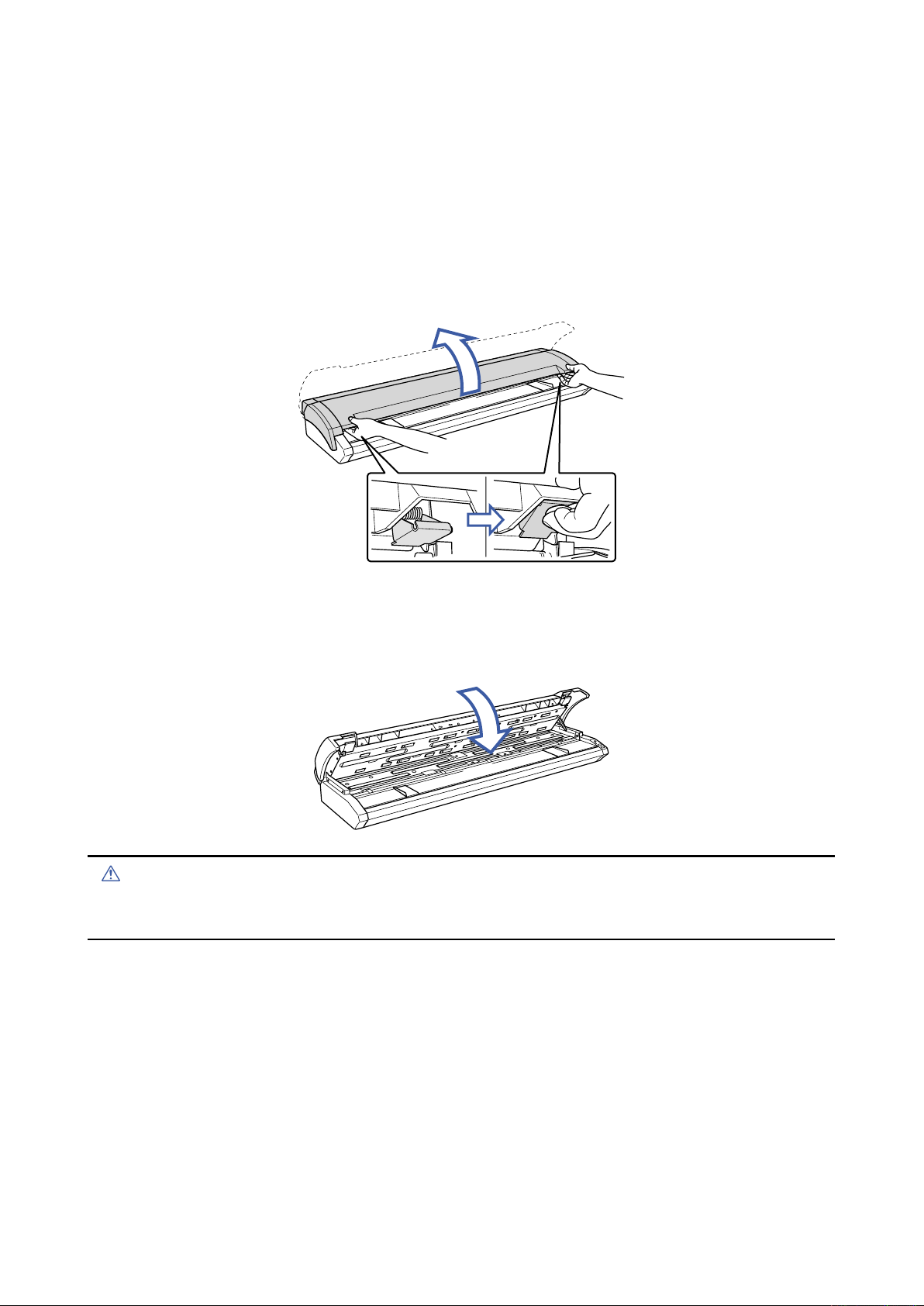
5.1 Opening and Closing the Top Cover
Opening the top cover
(1) Turn off the scanner.
(2) Using both hands, push up the left and right open levers on the top cover to unlock them.
While still holding on to the levers, open the cover fully (approximately 47 degrees).
(3) When the top cover is fully open, the fixing stay operates to hold the top cover in place.
Closing the top cover
(1) Press the open cover down gently with both hands to close it.
(2) Check that the left and right open levers are locked into position.
• Take care not to get your fingers caught when opening or closing the cover.
• If the levers are not locked correctly, the ERROR LED flashes and a scanning operation cannot be performed.
CSX300-UM-251-9370 5-1
Page 34
5. DAILY MAINTENANCE
Feedrollers
Caution
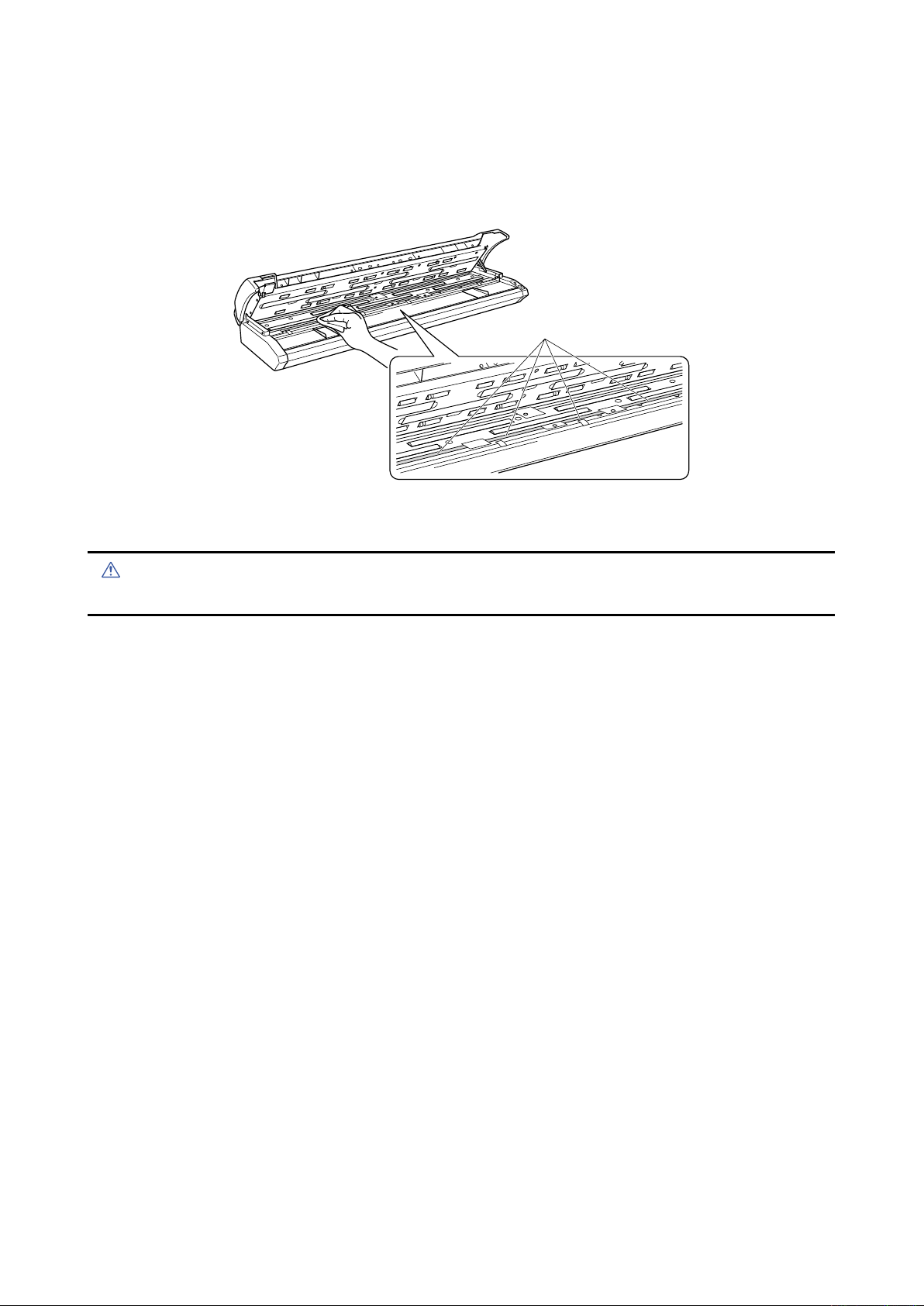
5.2 Cleaning the Feed Rollers
(1) Turn off the scanner.
(2) Open the top cover as described in Section 5.1, “Opening and Closing the Top Cover”.
(3) While rotating the feed rollers, wipe them clean using a soft cloth that has been moistened with water or
a neutral detergent (diluted with water) and firmly wrung out.
(4) Wipe the feed rollers once again using a soft, dry cloth to remove all the moisture.
(5) Close the top cover as described in Section 5.1, “Opening and Closing the Top Cover”.
• Take care not to get your fingers caught in the top cover.
CSX300-UM-251-9370 5-2
Page 35
5. DAILY MAINTENANCE
Documentsupportrollers
Caution
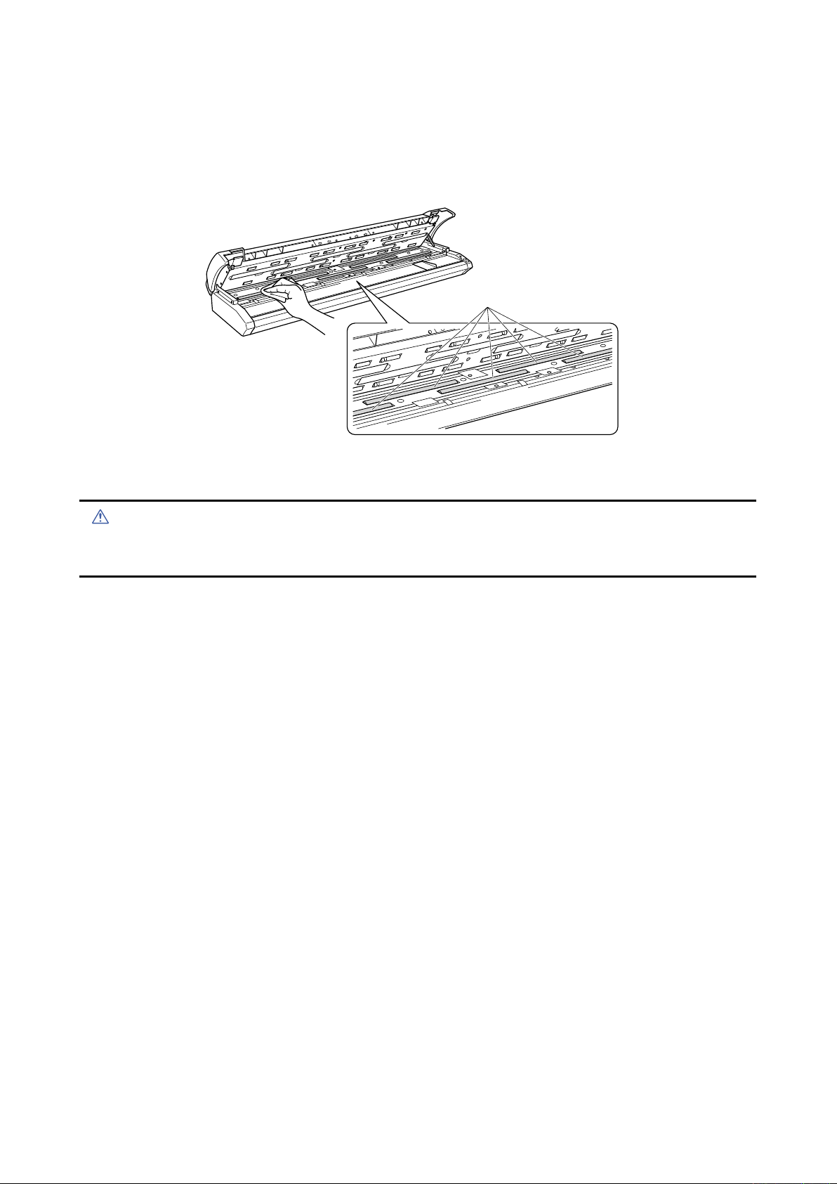
5.3 Cleaning the Document support Rollers
(1) Turn off the scanner.
(2) Open the top cover as described in Section 5.1, “Opening and Closing the Top Cover”.
(3) While rotating the document support rollers, wipe them clean using a soft cloth that has been moistened
with water or a neutral detergent (diluted with water) and firmly wrung out.
(4) Wipe the document support rollers once again using a soft, dry cloth to remove all the moisture.
(5) Close the top cover as described in Section 5.1, “Opening and Closing the Top Cover”.
• Take care not to get your fingers caught in the top cover.
• Scanning may be affected if the document support rollers becomes scratched or dirty.
CSX300-UM-251-9370 5-3
Page 36

5. DAILY MAINTENANCE
Gaprollers
Caution
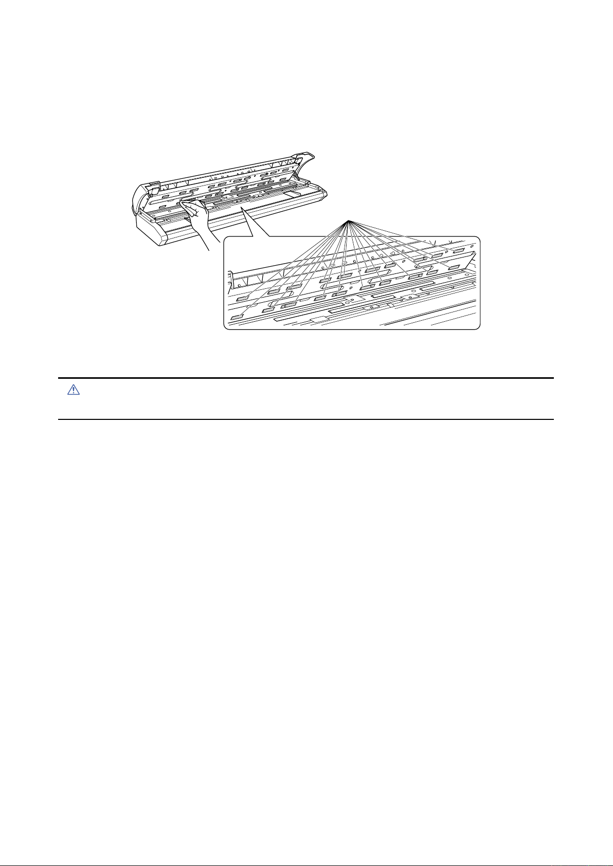
5.4 Cleaning the Gap Rollers
(1) Turn off the scanner.
(2) Open the top cover as described in Section 5.1, “Opening and Closing the Top Cover”.
(3) While rotating the gap rollers, wipe them clean using a soft cloth that has been moistened with water or
a neutral detergent (diluted with water) and firmly wrung out.
(4) Wipe the gap rollers once again using a soft, dry cloth to remove all the moisture.
(5) Close the top cover as described in Section 5.1, “Opening and Closing the Top Cover”.
• Take care not to get your fingers caught in the top cover.
CSX300-UM-251-9370 5-4
Page 37
5. DAILY MAINTENANCE
Pushrollers
Caution
5.5 Cleaning the Push Rollers
(1) Turn off the scanner.
(2) Open the top cover as described in Section 5.1, “Opening and Closing the Top Cover”.
(3) While rotating the push rollers, wipe them clean using a soft cloth that has been moistened with water or
a neutral detergent (diluted with water) and firmly wrung out.
(4) Wipe the push rollers once again using a soft, dry cloth to remove all the moisture.
(5) Close the top cover as described in Section 5.1, “Opening and Closing the Top Cover”.
• Take care not to get your fingers caught in the top cover.
CSX300-UM-251-9370 5-5
Page 38
5. DAILY MAINTENANCE
Transparentcontactplates
Caution
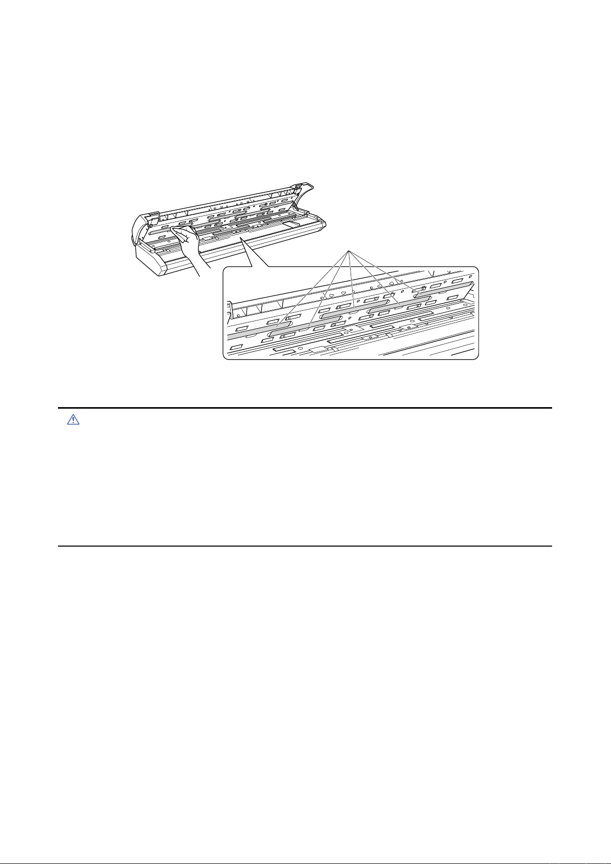
5.6 Cleaning the Image Sensors (Contact glass plates)
The scanner’s image quality drops when the contact glass plates over the image sensors become dirty, so
clean the image sensors whenever necessary.
(1) Turn off the scanner.
(2) Open the top cover as described in Section 5.1, “Opening and Closing the Top Cover”.
(3) As shown below, wipe off any soiled areas on the contact glass plates using a soft cloth that has been
moistened with water or a neutral detergent (diluted with water) and firmly wrung out.
(4) Wipe the contact glass plates once again using a soft, dry cloth to remove all the moisture.
(5) Close the top cover as described in Section 5.1, “Opening and Closing the Top Cover”.
• Take care not to get your fingers caught in the cover.
• Do not use a commercial cleaner for office equipment, a glass cleaner, or chemical solvents such as solutions
containing alcohol. Moreover, although the contact glass plates is not a maintenance part that requires periodic
replacement, it is a consumable part because its surface may receive slight scratches due to minute particles of
dust and other foreign matter. If document scanning produces unsatisfactory results (unexpected white or black
streaks in the data) due to scratches on one or more of the contact glass plates or other reasons, please perform
the calibration procedure (see Section 5.9, “Scanner Calibration”). If the scanning results do not improve after
calibration, the contact glass plate(s) will need to be replaced.
CSX300-UM-251-9370 5-6
Page 39
5. DAILY MAINTENANCE
documentsize
detectionsensors
Papersensors
Caution
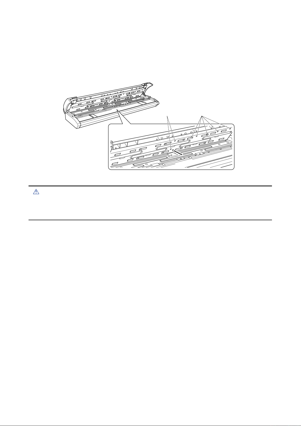
5.7 Cleaning the Media sensors
Accumulated dust on the paper sensors or on the document size detection sensors may prevent the
document from being scanned correctly. The sensors must be cleaned when necessary.
(1) Turn off the scanner.
(2) Open the top cover as described in Section 5.1, “Opening and Closing the Top Cover”.
(3) Wipe the media sensors (at the front and rear) using a cotton swab.
(4) Close the top cover as described in Section 5.1 “Opening and Closing the Top Cover”.
• Take care not to get your fingers caught in the top cover.
• Use a cotton swab or something equally soft to gently wipe the media sensors.
Do not use any chemicals to clean the sensors.
CSX300-UM-251-9370 5-7
Page 40
5. DAILY MAINTENANCE
Caution
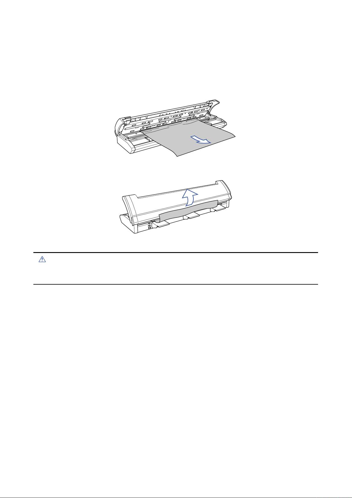
5.8 Removing a Jammed Document
If a document becomes jammed in the scanner during scanning or another operation, follow the procedure
described below to remove the jammed document.
(1) Turn off the scanner.
(2) Open the top cover as described in Section 5.1 “Opening and Closing the Top Cover”.
(3) If the document is jammed at the front, remove the document from the inside by pulling it forward.
(4) If the document is jammed at the rear, remove the document by pulling it out along the rear guides.
(5) Close the top cover as described in Section 5.1, “Opening and Closing the Top Cover”.
• Take care not to get your fingers caught in the top cover.
• When removing a jammed document, pull on it gently to prevent damage to the document.
CSX300-UM-251-9370 5-8
Page 41

5. DAILY MAINTENANCE
Checkpoint
5.9 Scanner Calibration
Calibrate the scanner if scanning quality is observed to deteriorate, with scanned results such as those
described below
• The scanned image is distorted
• Areas of uneven color appear in the scanned image
• Other unsatisfactory results (but excluding problems related to media quality, such as folds, creases, or
paper curl)
Preparation and checks
Recommended usage environment
• Monitor: 1024 x 768 pixels, High Color or better resolution
A low-resolution monitor will make it difficult to discern any problem areas.
Launching the Scanner Adjustment Program
(1) Connect the scanner to the computer, turn on the scanner, and then turn on the computer.
(2) Install the Scanning Master 21+ “OPS112” software if it is not already installed.
(3) Click the [Start] button on the Windows desktop, then select Programs > Scanning Master 21+ >
Scanner Adjustment.
(4) Click Scanner Adjustment to launch the Scanner Adjustment program.
(5) Select the desired adjustment item from the Scanner menu.
CSX300-UM-251-9370 5-9
Page 42

5. DAILY MAINTENANCE
Caution
Checkpoint
Calibration sheet
Arrow mark
Scanner
Insertion direction
Calibration
Before beginning calibration, clean the contact glass plates located inside the scanner and the surface of
the document-scanning table. Any dust or dirt on these surfaces may affect the calibration results and the
resulting image quality.
Check that the calibration sheet is free of any dust or dirt.
• The calibration procedure will take some time. Do not turn off the scanner while calibration is underway.
Accidentally turning off the scanner may result in damage that requires servicing.
• Handle the calibration sheet with care so that it does not get bent. To prevent soiling, store it in its special storage
box.
• The calibration sheet is a consumable item. It cannot be used if it is bent or soiled.
• The calibration sheet is a paper product. Do not attempt to clean it with any type of liquid cleaner.
A prompt instructing you to insert the calibration sheet in the scanner will be displayed in Step 3. At that time, insert
the calibration sheet as instructed, with the arrow at the top, as shown in the diagram below.
(1) Launch the Scanner Adjustment program (as described earlier), and then display the Scanner menu.
Select Calibration on the Scanner menu.
(2) Select All in Calibration and click the [Execute] button.
(3) The following prompt is displayed. Insert the calibration sheet into the scanner as instructed.
(4) Click the [OK] button to begin calibration.
(5) Calibration ends after approximately 10 minutes.
Click the [OK] button to complete calibration.
CSX300-UM-251-9370 5-10
Page 43

5. DAILY MAINTENANCE
(6) To check the calibration results, click the [Confirm] button in the Calibration screen (shown in step (2)
above).
(7) The following prompt is displayed. Insert the calibration sheet into the scanner once again as instructed.
(8) Click the [OK] button to start scanning.
The scanned data is displayed when scanning is complete. Colors may differ slightly for individual
sensors to make it easier to identify problem areas in calibration. This does not indicate a defect.
Check that there are no vertical streaks, such as white patches, in the scanned data.
(Streaks occur when calibration is not performed correctly due to contamination by dust or dirt.)
(9) If the data is normal, calibration is complete. Click the [Close] button and exit the Scanner Adjustment
Program.
(10) If any abnormal data is observed, specify the problem areas as follows:
Select Calibration from the Scanner menu, and then select Specified Part in the Calibration screen.
(11) The mouse arrow cursor changes to a cross cursor when moved over the data. Click the left mouse
button with the mouse positioned over the streak data. The selected area is shown in blue. Repeat this
procedure for any additional streaks.
Areas that have been selected (shown in blue) can be deselected by clicking the left mouse button
again. To deselect all selected areas, click the [Clear] button.
(12) Once all the required areas have been specified, remove the calibration sheet and clean the contact
glass plates and document-scanning table surface. Check the calibration sheet for dust and dirt.
(13) Click the [Execute] button and then follow the instructions displayed on the screen. The procedure will
be the same as that described in Steps (3) to (5) above. (The time required for calibration will vary
according to the number of repeats specified.)
(14) Perform Steps (8) to (10) once more, and verify the calibration results.
CSX300-UM-251-9370 5-11
Page 44

Page 45

6. RECOMMENDED PARTS LIST
6. RECOMMENDED PARTS LIST
No. Part No. Part Name Description Q'ty Remarks RL
444063052 SVC_Main_BD_S Main Board 1 A
1
2 444063101 SVC_CIS_BD CIS Control Board 5
3 444063083 SVC_PWR_BD CIS Power Board 1
4 444063601 Right_Side_Cover_A
5 444063825 Scan_Glass_A Contact Glass Plate Assy 5 A
6 444063891 Calibration Sheet (IS0925)
7 641710002 Feed_Roller_F Front Feed Roller 1 B
8 641710012 Feed_Roller_R Rear Feed Roller 1 B
9 444063722 Pinch_Roller_A Pinch Roller Assy 20 B
10 561080004 Media_Sensor PS117ED1 7 B
11
444063681 Press_Roller_A Document Roller Assy 5 B
12 694450111 FPC_Cable FPC, CS20A, CIS to CIS B 5 A
13 561080012 Cover_Sensor KI139 1-AALF 2 B
444065201 CIS Sensor A, (Rank A)
444065211 CIS Sensor B, (Rank B)
444065221 CIS Sensor C, (Rank C)
14
444065231 CIS Sensor D, (Rank D)
444065251 CIS Sensor F, (Rank F)
444065261 CIS Sensor G, (Rank G)
444065271 CIS Sensor H, (Rank H)
With Control Panel Relay Board
IS0925 (Ordered by this options model name)
Select the same rank of sensor
that is used in your scanner.
1 B
1 A
5 A
A
A
CSX300-UM-251-9370 6-1
Page 46

Page 47

7. LIST OF JIGS AND TOOLS
7. LIST OF JIGS AND TOOLS
7.1 Jigs
Jigs Adjustments Remarks
CSX300-09 firmware •Downloading system program Firmware (CSX300.X)
Scanning Master 21+
(Ver. 6.60 or later)
Calibration sheet •Shading (white & black correction) Standard accessory
Adjustment test chart for CSX300 •Adjusting feed distance
Auto adjustment chart •Aligning sensor images Auto adjustment chart
7.2 Tools
Tools Usage Remarks
Screwdriver
Allen wrench (2 mm to 4 mm)
Needle-nose pliers
7.3 Other
Item Usage Remarks
Water-diluted neutral detergent or
absolute ethanol wiper (cloth)
PC
USB cable
•Downloading system program
•Shading (white & black correction)
•Adjusting feed distance
•Aligning sensor images
•Adjusting offset
•Adjusting offset
•Aligning sensor images
Disassembly, reassembly, and other
operations
Cleaning
Used to determine whether the problem
is caused by the scanner or other
equipment.
Software supplied with the scanner
(Scanning Master 21+)
1050 mm x 200 mm
Record measured values between C010
and C090.
Large, medium, and small flat blade
screwdrivers and Phillips screwdrivers
CSX300-UM-251-9370 7-1
Page 48

Page 49
8. DISASSEMBLING AND ADJUSTING THE MECHANICAL PARTS
8.
DISASSEMBLING AND ADJUSTING THE MECHANICAL PARTS
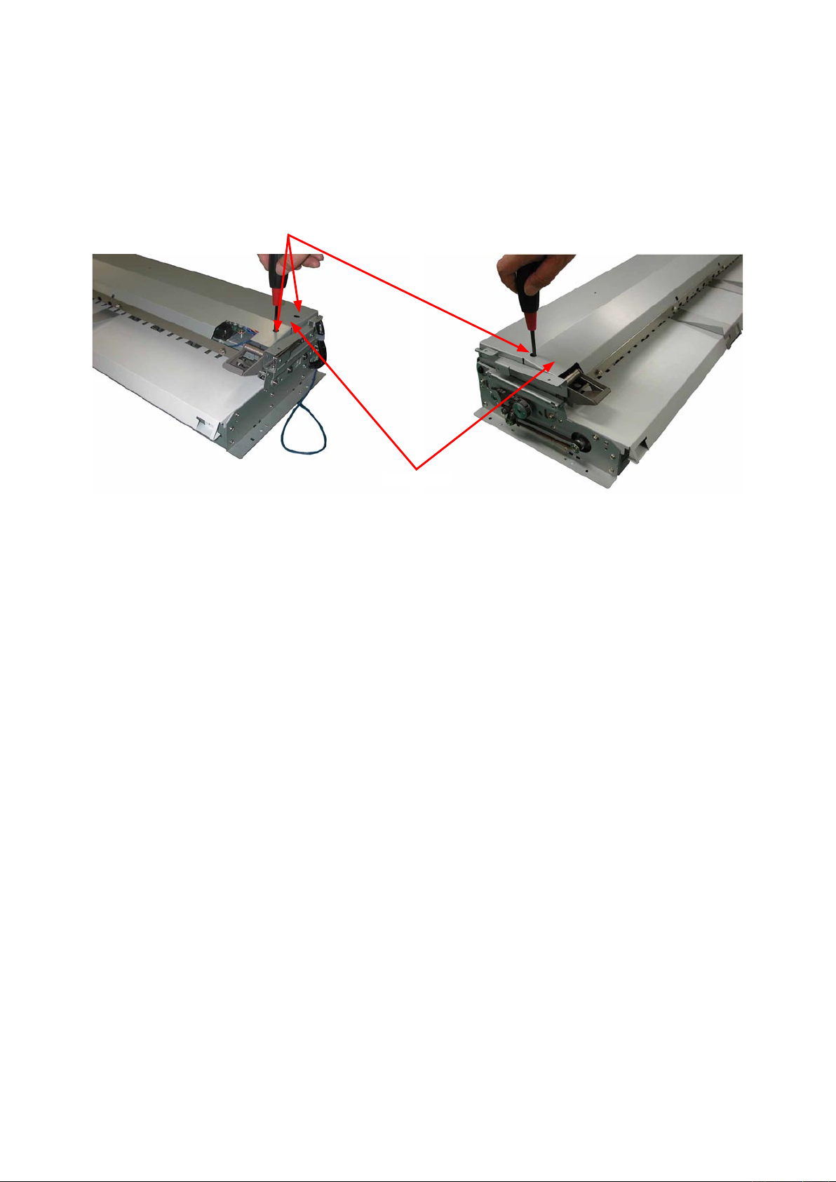
8.1 Top Cover
Detaching the top cover
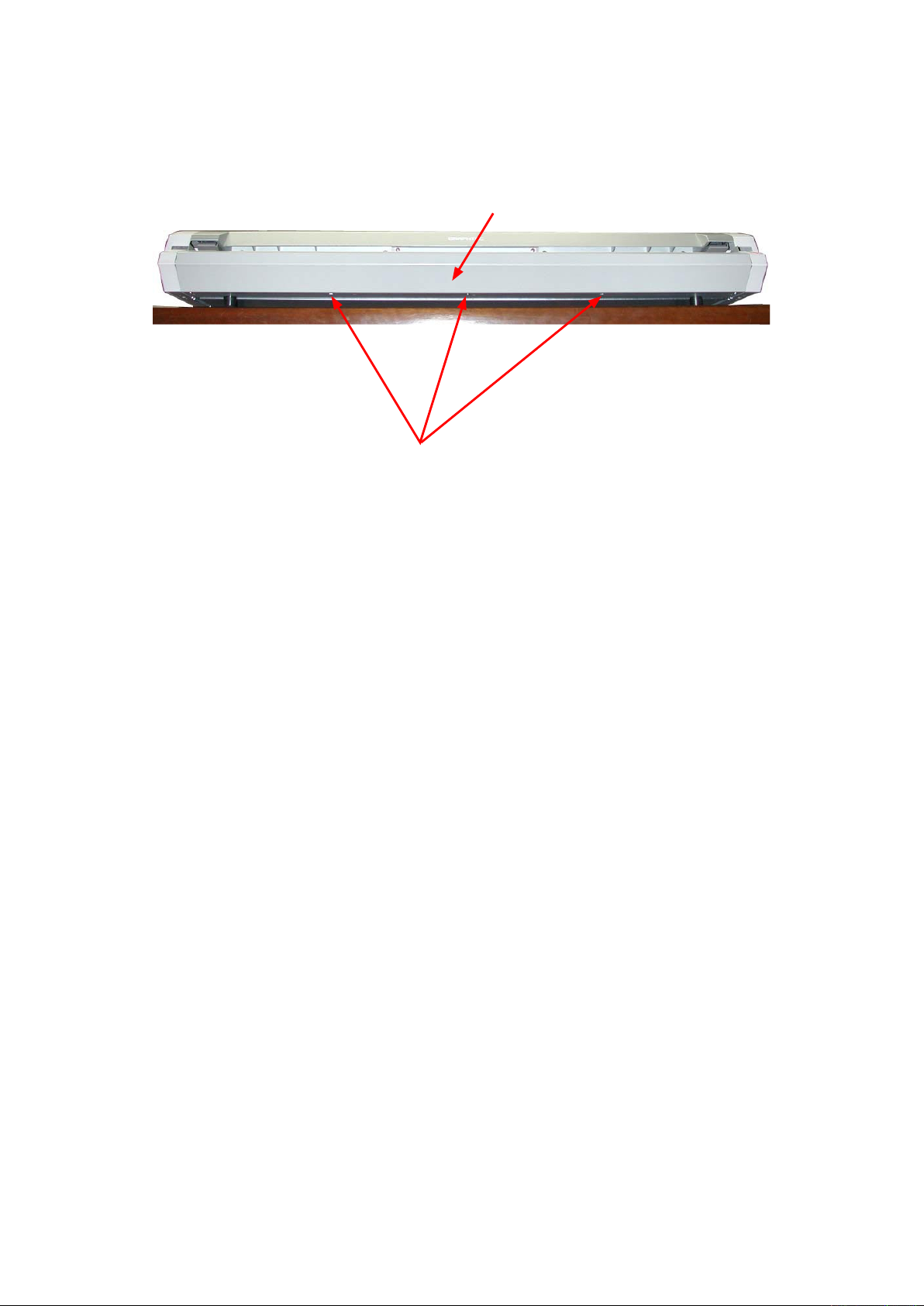
(1) Remove the four M4L8 binding head screws on the front side of the top cover.
Top cover
M4L8 binding head screw
(2) Remove the four M4L8 binding head screws on the rear side of the top cover.
Top cover
M4L8 binding head screw
(3) Detach the top cover from the scanner unit in the upward direction.
Reattaching the top cover
(1) Reattach the top cover in the reverse order in which it was detached.
CSX300-UM-251-9370 8-1
Page 50
8. DISASSEMBLING AND ADJUSTING THE MECHANICAL PARTS
8.2 Front Cover
Detaching the front cover
(1) Remove the three M4L8 thin flat head screws holding the front cover.
Front cover
M4L8 thin flat head screw
(2) Pull out the front cover from the scanner unit.
Reattaching the front cover
(1) Reattach the front cover in the reverse order in which it was detached.
CSX300-UM-251-9370 8-2
Page 51
8. DISASSEMBLING AND ADJUSTING THE MECHANICAL PARTS
8.3 Left Side Cover
Detaching the left side cover
(1) Detach the top cover (see Section 8.1).
(2) Detach the front cover (see Section 8.2).
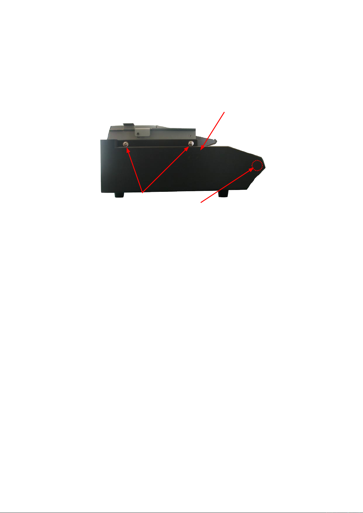
(3) Remove the two M4L8 TP screws on the left side of the scanner unit.
(4) Detach the left side cover.
Left side cover
M4L8 TP screw
Note:
There is a positioning pillar inside the left side cover.
Do not twist the cover when removing the cover.
Otherwise, you will break the positioning pillar.
Reattaching the left side cover
(1) Reattach the left side cover in the reverse order in which it was detached.
CSX300-UM-251-9370 8-3
Page 52
8. DISASSEMBLING AND ADJUSTING THE MECHANICAL PARTS
8.4 Right Side Cover
Detaching the right side cover
(1) Detach the top cover (see Section 8.1).
(2) Detach the front cover (see Section 8.2).
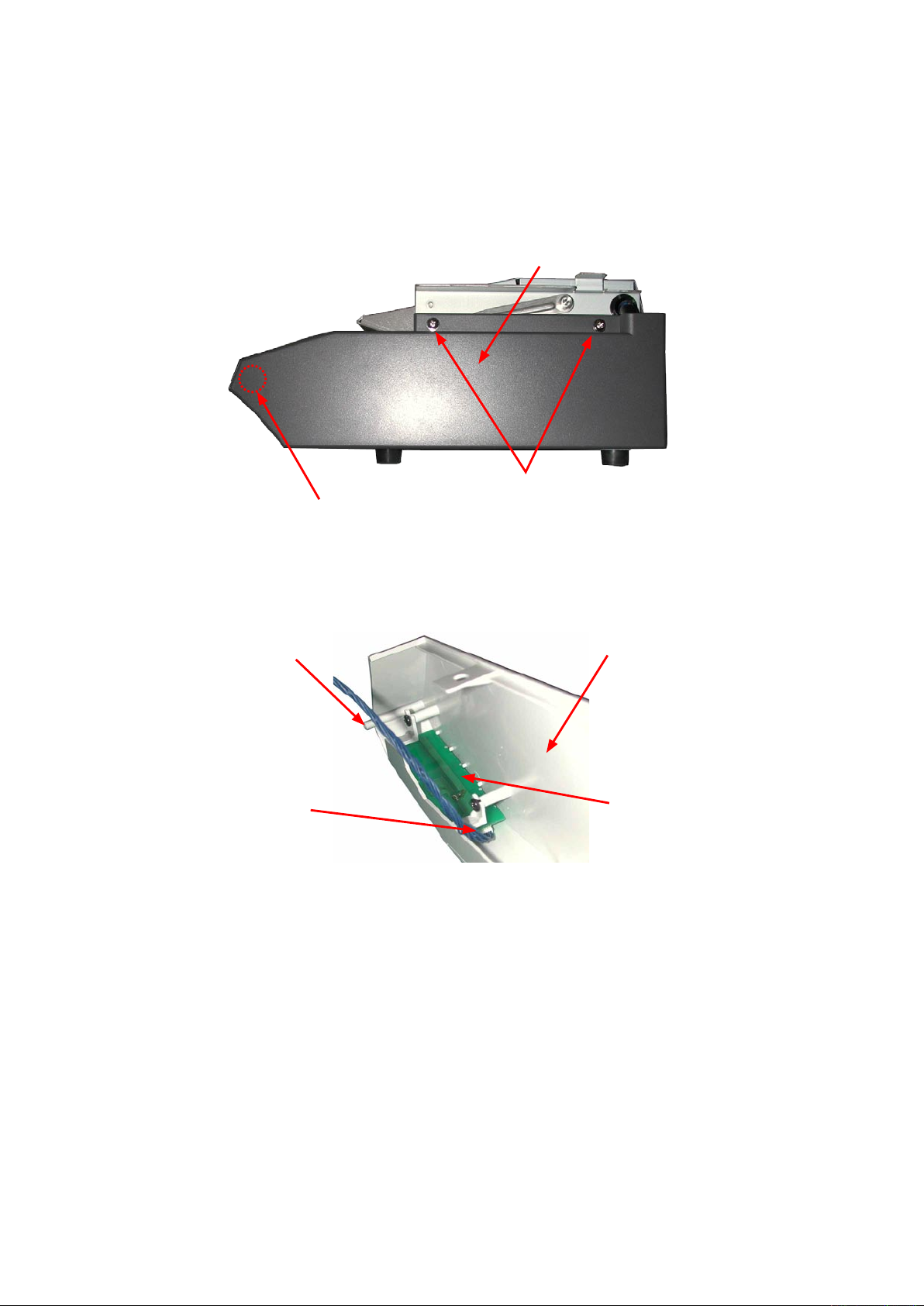
(3) Remove the two M4L8 TP screws on the right side of the scanner unit.
Right side cover
M4L8 TP screw
Note:
There is a positioning pillar inside the right side cover.
Do not twist the cover when removing the cover.
Otherwise, you will break the positioning pillar.
(2) Disconnect the control panel cable from the control panel board.
Positioning pillar
Control panel cable
Right side cover
Control panel board
(3) Detach the right side cover.
Reattaching the right side cover
(1) Reattach the right side cover in the reverse order in which it was detached.
CSX300-UM-251-9370 8-4
Page 53
8. DISASSEMBLING AND ADJUSTING THE MECHANICAL PARTS
8.5 Front Guide Assembly
Detaching the front guide assembly
(1) Detach the top, front, left side and right covers (see Sections 8.1, 8.2, 8.3 and 8.4).
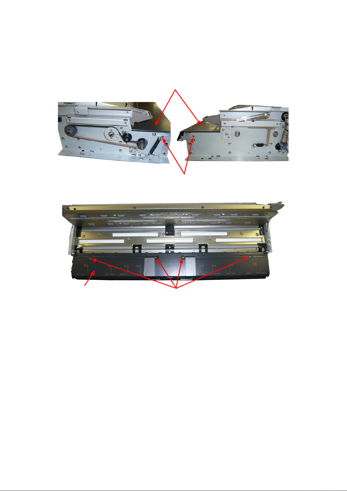
(2) Remove the two M3L6 binding head screws holding the front guide assembly from each side.
Front guide assembly
M3L6 binding head screw
(2) Remove the four M3L6 binding head screws holding the front guide assembly.
Front guide assembly
(3) Detach the front guide assembly from the scanner unit.
M3L6 binding head screw
Reattaching the front guide assembly
(1) Reattach the front guide assembly in the reverse order in which it was detached.
CSX300-UM-251-9370 8-5
Page 54
8. DISASSEMBLING AND ADJUSTING THE MECHANICAL PARTS
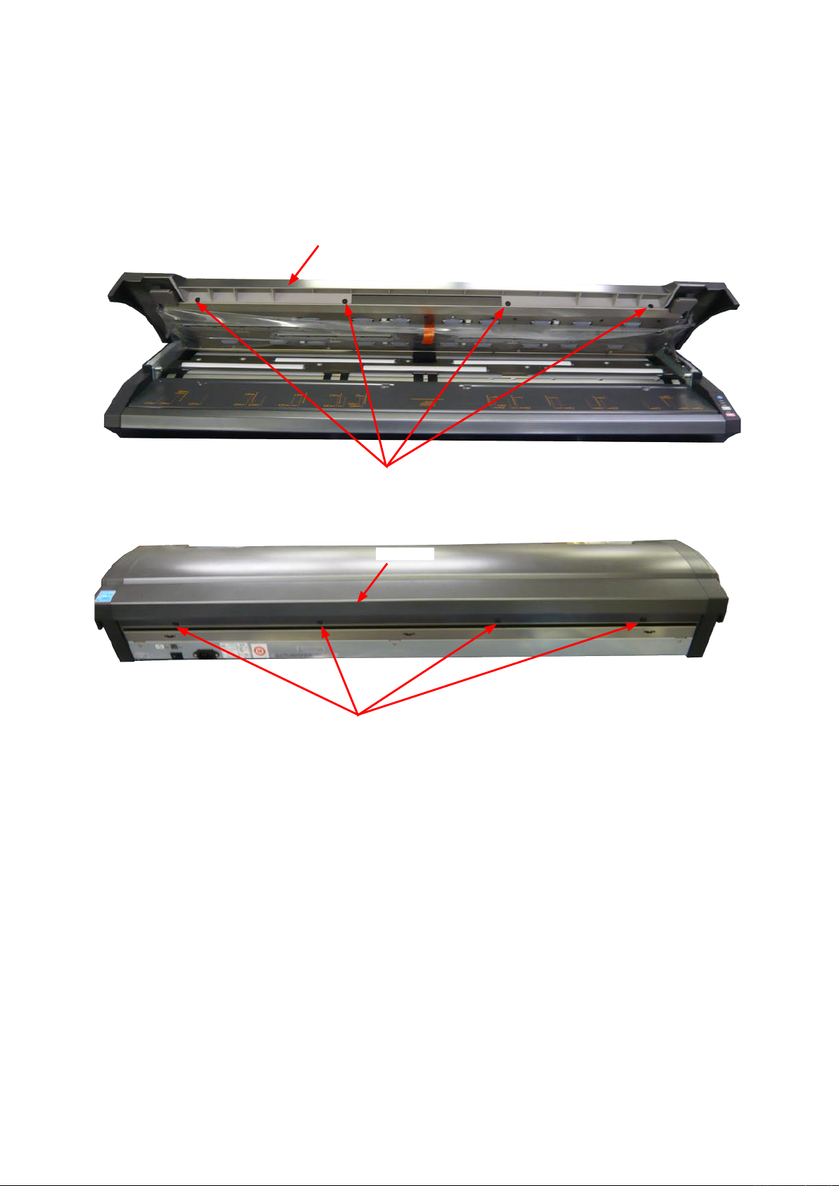
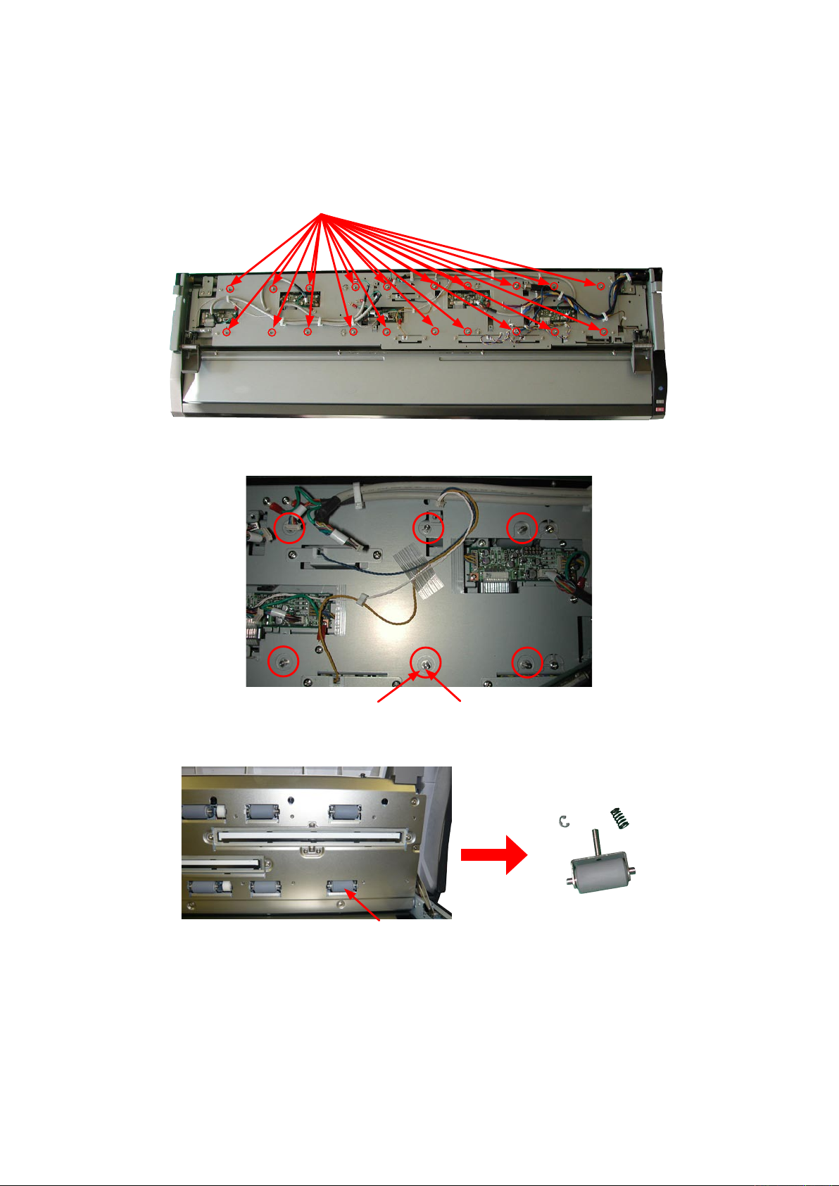
8.6 Shield Cover
Detaching the shield cover
(1) Detach the top cover (see Section 8.1).
(2) Remove the three M3L4 binding head screws from the access holes of the shield cover as shown in the
photographs below.
M3L4 binding head screw
Shield cover
(3) Detach the shield cover.
Reattaching the rear cover
(1) Reattach the shield cover in the reverse order in which it was detached.
CSX300-UM-251-9370 8-6
Page 55
8. DISASSEMBLING AND ADJUSTING THE MECHANICAL PARTS
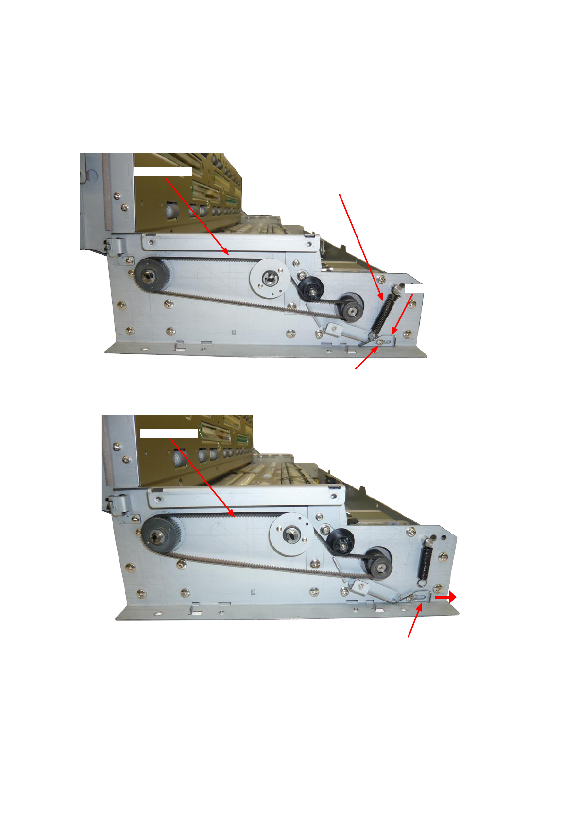
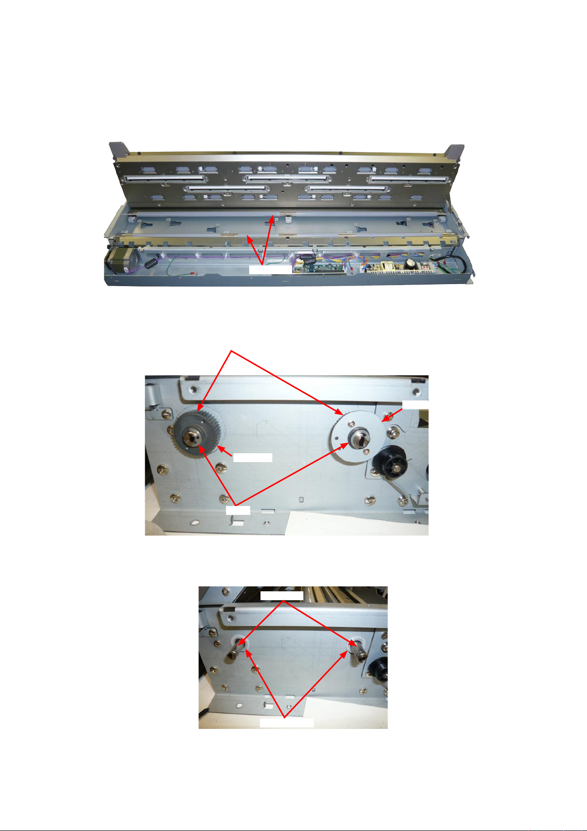
8.7 Feed Drive Belt
Detaching the feed drive belt
(1) Detach the top cover (see Sections 8.1).
(2) Detach the front covers (see Section 8.2).
(3) Detach the left side cover (see Sections 8.3).
Feed drive belt
Tension spring
Tension stopper bracket
(4) Detach the tension spring from the feed belt tension pin.
Feed drive belt
M2L6 binding head screw
Tension stopper bracket
(5) Loosen the M2L5 binding screw holding the tension stopper bracket, and then slide it to right side.
(6) Detach the feed drive belt from the feed pulley.
CSX300-UM-251-9370 8-7
Page 56
8. DISASSEMBLING AND ADJUSTING THE MECHANICAL PARTS
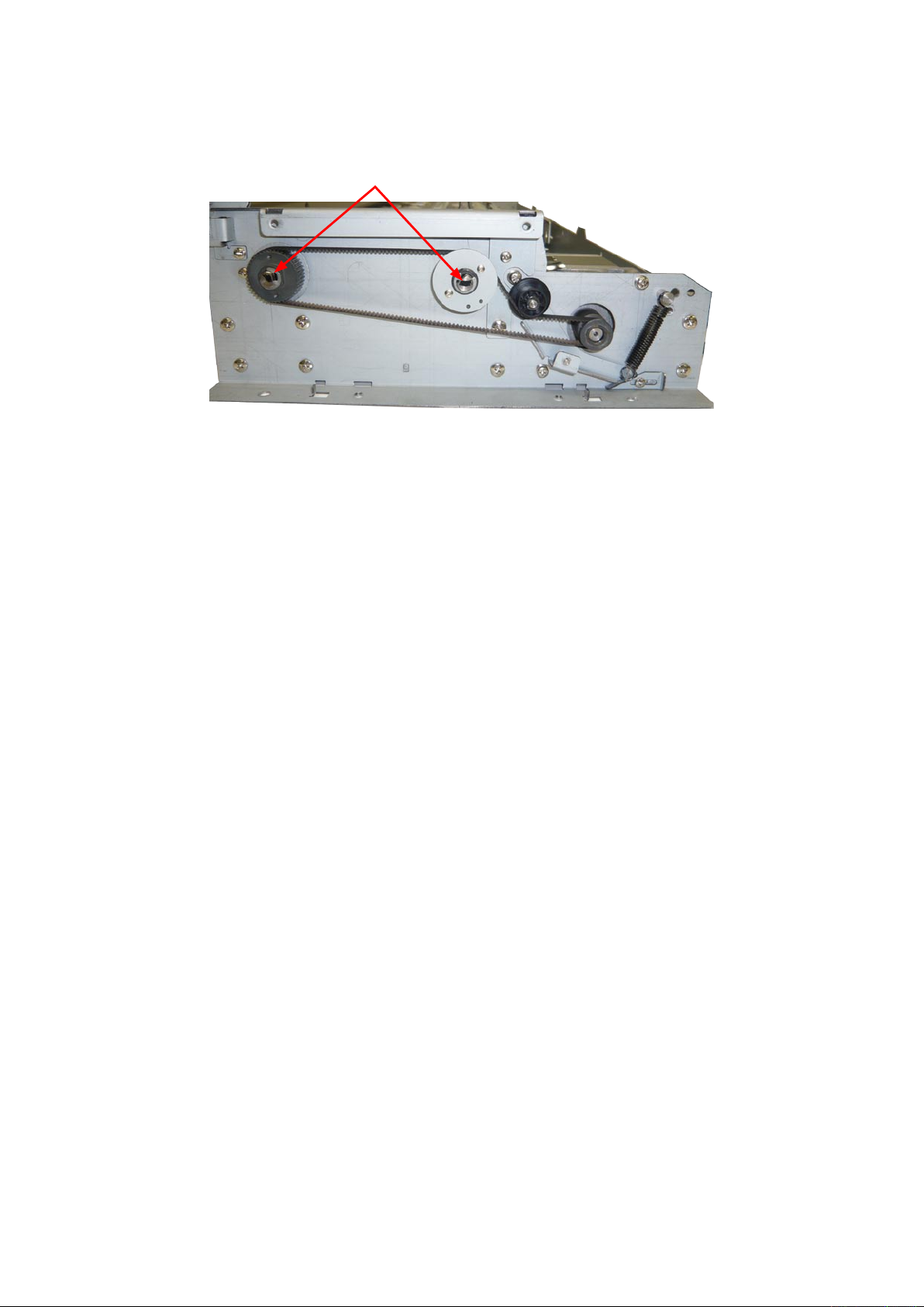
Reattaching the feed drive belt
(1) Reattach the feed drive belt by reversing the sequence of steps in which it was detached.
These black lines should be parallel
when installing the feed drive belt.
CSX300-UM-251-9370 8-8
Page 57
8. DISASSEMBLING AND ADJUSTING THE MECHANICAL PARTS
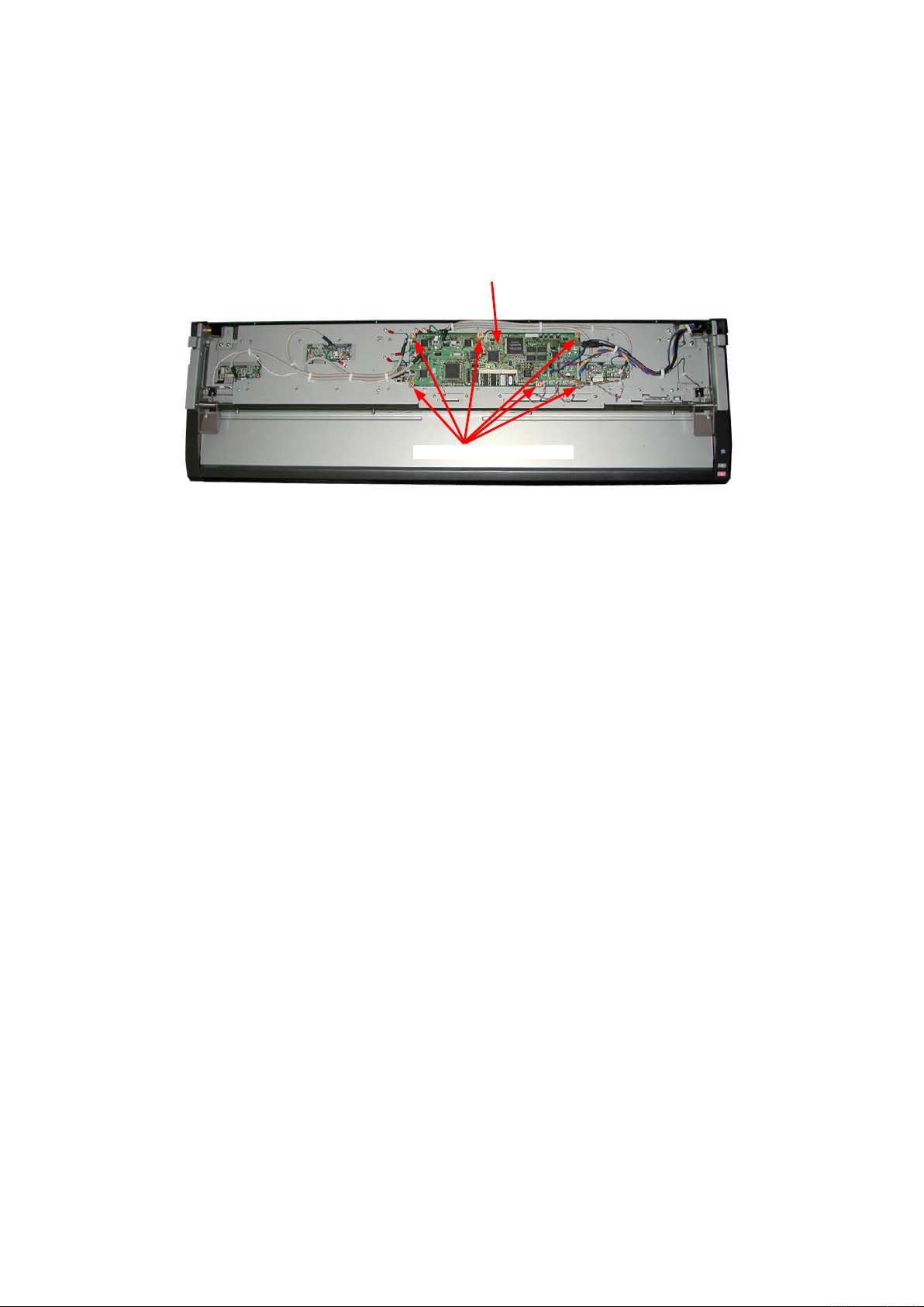
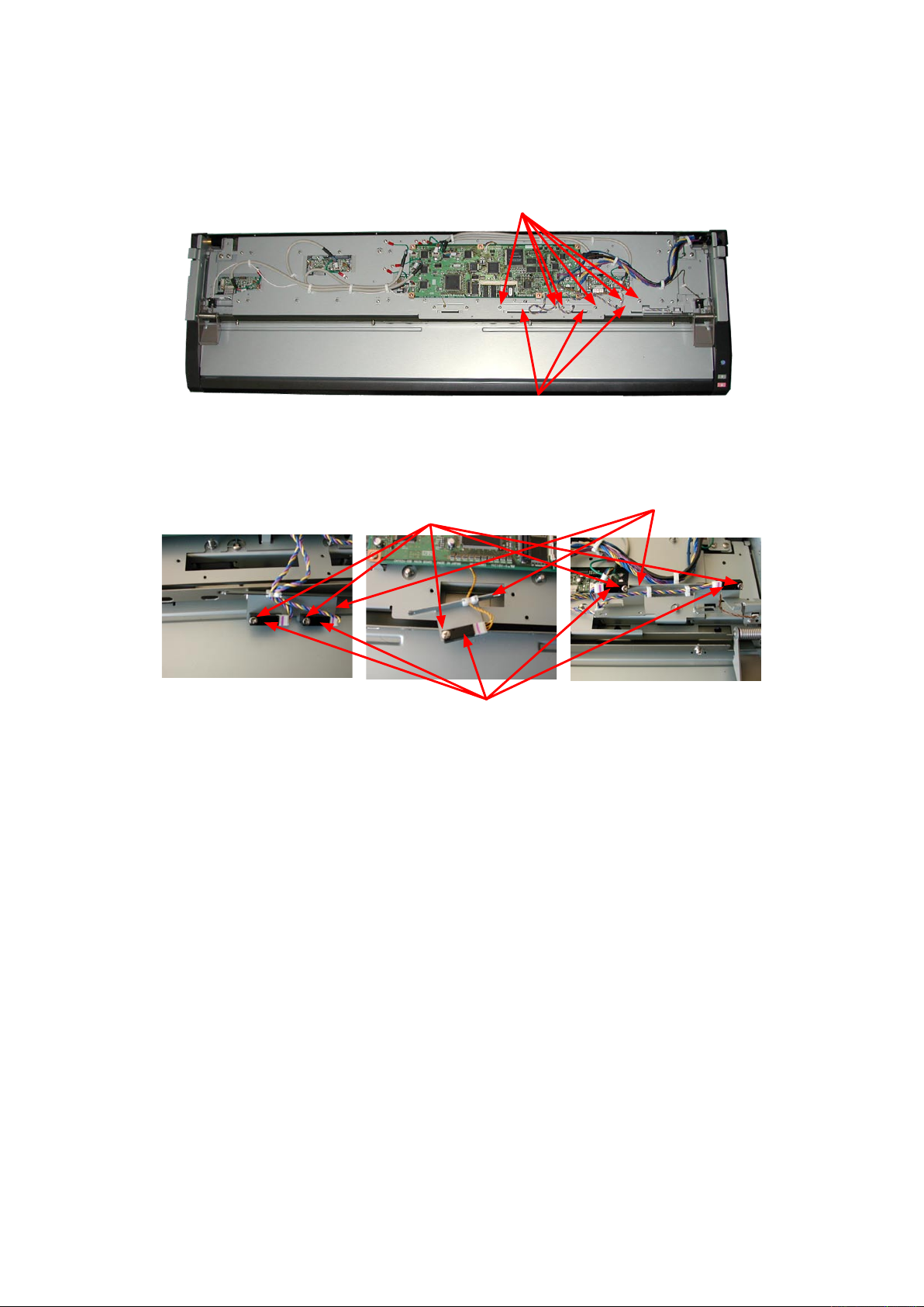
8.8 Main Board
Detaching the main board
(1) Detach the top and shield covers (see Sections 8.1 and 8.6).
(2) Disconnect the all cables from the main board.
(3) Remove the six M3L6 binding head screws holding the main board.
(4) Detach the main board from the board base bracket.
Main board
M3L6 binding head screw
Reattaching the main board
(1) Reattach the main board by reversing the sequence of steps in which it was detached.
(2) Perform the calibration and the software adjustment if the main board was replaced.
CSX300-UM-251-9370 8-9
Page 58

8. DISASSEMBLING AND ADJUSTING THE MECHANICAL PARTS
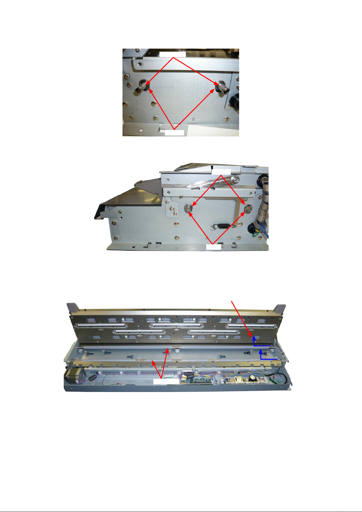
8.9 Board Base Chassis
Detaching the board base chassis
(1) Detach the top and shield covers (see Sections 8.1 and 8.6).
(2) Detach the main board. (see Sections 8.8).
(3) Remove the eight M3L6 binding head screws holding the board base chassis.
M3L6 binding head screw
Board base chassis
(4) Disconnect the cables from the CIS boards.
CIS board
Board base chassis
(5) Lay the board base chassis down at the rear of the main unit as shown below.
Board base chassis
Reattaching the board base chassis
(1) Reattach the board base chassis by reversing the sequence of steps in which it was detached.
CSX300-UM-251-9370 8-10
Page 59

8. DISASSEMBLING AND ADJUSTING THE MECHANICAL PARTS
8.10 CIS Board
Detaching the CIS board
(1) Detach the top and shield covers (see Sections 8.1 and 8.6).
(2) Detach the main board. (see Sections 8.8).
(3) Detach the board base chassis. (see Sections 8.9).
Board base chassis
CIS board
(4) Remove the two M2L5 binding head screws holding the CIS board.
M2L5 binding head screw
CIS board
(5) Disconnect the cables from the CIS board.
(6) Detach the CIS board from the main unit.
Reattaching the board base chassis
(1) Reattach the CIS board by reversing the sequence of steps in which it was detached.
(2) Perform the calibration if the CIS board was replaced.
CSX300-UM-251-9370 8-11
Page 60

8. DISASSEMBLING AND ADJUSTING THE MECHANICAL PARTS
8.11 CIS Sensor
Detaching the CIS sensor
(1) Detach the top and shield covers (see Sections 8.1 and 8.6).
(2) Detach the main board. (see Sections 8.8).
(3) Detach the board base chassis. (see Sections 8.9).
(4) Detach the CIS board. (see Sections 8.10).
(5) Remove the four M3L4 binding head screws holding the CIS sensor bracket, and then detach the CIS
sensor bracket.
M3L4 binding head screws
CIS sensor bracket
(6) Detach the CIS sensor from the main unit.
CIS sensor
Reattaching a CIS sensor
(1) Reattach the CIS sensor by reversing the sequence of steps in which it was detached.
(2) Use a CIS sensor of the same rank when replacing a CIS sensor.
The CIS sensor rank is indicated on the CIS sensor unit and the bottom of the scanner chassis.
(3) Perform the calibration and the software adjustment if the main board was replaced.
CSX300-UM-251-9370 8-12
Page 61

8. DISASSEMBLING AND ADJUSTING THE MECHANICAL PARTS
How to find out the CIS sensor rank
There is the CIS sensor rank label on the bottom chassis as shown in a picture below. So prepare same rank
of the CIS sensor before replacing the CIS sensor.
CSX300-UM-251-9370 8-13
Page 62

8. DISASSEMBLING AND ADJUSTING THE MECHANICAL PARTS
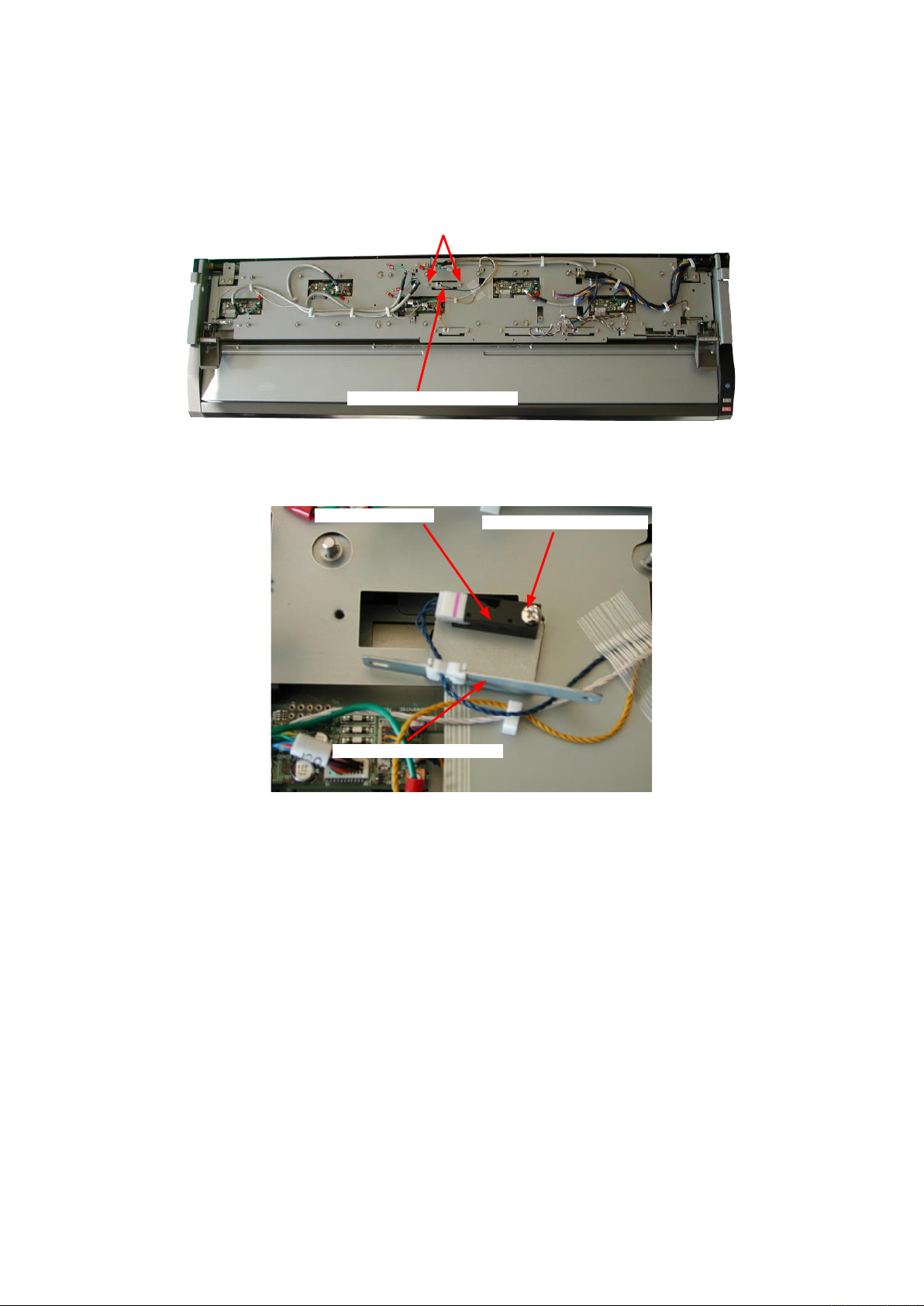
8.12 Cover Sensor
Detaching the cover sensor
(1) Detach the top and shield covers (see Sections 8.1 and 8.6).
Cover sensor
(2) Remove the M3L6 binding head screw holding the cover sensor.
Cover sensor
M3L6 binding head screw
(3) Disconnect the cable that is connected to the cover sensor.
(4) Detach the cover sensor from the board base assembly.
Reattaching the cover sensor
(1) Reattach the cover sensor by reversing the sequence of steps in which it was detached.
CSX300-UM-251-9370 8-14
Page 63

8. DISASSEMBLING AND ADJUSTING THE MECHANICAL PARTS
8.13 Front Media Sensor
Detaching the front media sensor
(1) Detach the top and shield covers (see Sections 8.1 and 8.6).
M3L6 binding head screw
Front media sensor bracket
(2) Remove the tow M3L6 binding head screws holding the front media sensor bracket.
(3) Disconnect the cable that is connected to the front media sensor.
Front media sensor bracket
M3L12 binding head screw
(4) Remove the M3L12 binding head screws holding the front media sensor.
(5) Detach the front media sensor from the front media sensor bracket.
Front media sensor
Reattaching the front media sensor
(1) Reattach the front media sensor by reversing the sequence of steps in which it was detached.
(2) Perform the software adjustment (scanning start position adjustment) if the front media sensor was
replaced.
CSX300-UM-251-9370 8-15
Page 64
8. DISASSEMBLING AND ADJUSTING THE MECHANICAL PARTS
8.14 Rear Media Sensor
Detaching the rear media sensor
(1) Detach the top and shield covers (see Sections 8.1 and 8.6).
(2) Detach the main board. (see Sections 8.8).
M3L6 binding head screw
Rear media sensor bracket
(3) Remove the tow M3L6 binding head screws holding the rear media sensor bracket.
(4) Disconnect the cable that is connected to the rear media sensor.
Rear media sensor
Rear media sensor bracket
(5) Remove the M3L12 binding head screws holding the rear media sensor.
(6) Detach the rear media sensor from the rear media sensor bracket.
M3L12 binding head screw
Reattaching the rear media sensor
(1) Reattach the rear media sensor by reversing the sequence of steps in which it was detached.
(2) Perform the software adjustment (scanning start position adjustment) if the rear media sensor was
replaced.
CSX300-UM-251-9370 8-16
Page 65
8. DISASSEMBLING AND ADJUSTING THE MECHANICAL PARTS
8.15 Media width sensors
Detaching the media width sensors
(1) Detach the top and shield covers (see Sections 8.1 and 8.6).
M3L6 binding head screw
Media width sensor bracket
(2) Remove the tow M3L6 binding head screws holding the media width sensor brackets.
(3) Disconnect the cable that is connected to the media width sensors.
M3L12 binding head screw
Media width sensor
(4) Remove the M3L12 binding head screws holding the media width sensors.
(5) Detach the media width sensors from the media width sensor brackets.
Media width sensor bracket
Reattaching the media width sensors
(1) Reattach the media width sensors by reversing the sequence of steps in which they were detached.
CSX300-UM-251-9370 8-17
Page 66
8. DISASSEMBLING AND ADJUSTING THE MECHANICAL PARTS
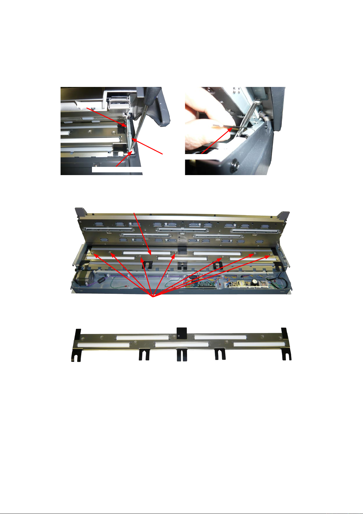
8.16 Document Roller Assembly
Detaching the document roller assembly
(1) Detach the top, front, left side and right side covers (see Sections 8.1, 8.2, 8.3 and 8.4).
(2) Remove the M3L6 binding head screw holding the flap stay stopper bracket.
Flap stay
Flap stay stopper bracket
M3L6 binding head screw
(3) Detach the flap stay stopper bracket.
(4) Remove the seven M3L6 binding head screws holding the document roller assembly.
Document roller assembly
M3L6 binding head screw
(5) Detach the document roller assembly from the main unit.
Reattaching the document roller assembly
(1) Reattach the document roller assembly by reversing the sequence of steps in which it was detached.
(2) Perform the calibration and the software adjustment if the document roller assembly was replaced or
detached.
CSX300-UM-251-9370 8-18
Page 67
8. DISASSEMBLING AND ADJUSTING THE MECHANICAL PARTS
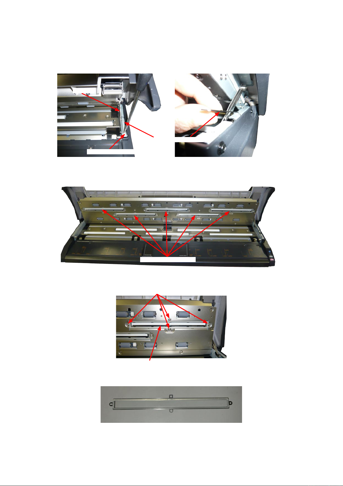
8.16 Contact Glass Assembly
Detaching the contact glass assembly
(1) Remove the M3L6 binding head screw holding the flap stay stopper bracket.
Flap stay
Flap stay stopper bracket
M3L6 binding head screw
(2) Detach the flap stay stopper bracket.
(3) Open the top cover.
Contact glass assembly
(4) Remove the four M3L6 binding head screws holding the contact glass assembly.
M3L6 binding head screw
Contact glass assembly
(5) Detach the contact glass assembly from the top cover unit.
CSX300-UM-251-9370 8-19
Page 68

8. DISASSEMBLING AND ADJUSTING THE MECHANICAL PARTS
Reattaching the contact glass assembly
(1) Reattach the contact glass assembly by reversing the sequence of steps in which it was detached.
(2) Keep clean the surface of the contact glass assembly and do not make the finger-print on glass when
installing the contact glass.
(3) Blow out any dust from the surface of the CIS sensor when installing the contact glass.
(4) Perform the calibration and the software adjustment if the contact glass assembly was replaced or
detached.
CSX300-UM-251-9370 8-20
Page 69
8. DISASSEMBLING AND ADJUSTING THE MECHANICAL PARTS
8.17 Pinch Roller
Detaching the pinch roller
(1) Detach the top and shield covers (see Sections 8.1 and 8.6).
(2) Detach the main board when the pinch roller under the main board is replaced. (see Sections 8.8).
Pinch roller holder shaft
(3) Remove the E-ring holding the pinch roller holder shaft.
E-ring
(4) Detach the pinch roller and the spring from the bottom of the top cover unit.
Pinch roller
Pinch roller holder shaft
Reattaching the pinch roller
(1) Reattach the pinch roller by reversing the sequence of steps in which it was detached.
(2) Perform the calibration and the software adjustment if the pinch roller was replaced or detached.
CSX300-UM-251-9370 8-21
Page 70
8. DISASSEMBLING AND ADJUSTING THE MECHANICAL PARTS
8.18 Feed Rollers
Detaching the feed rollers
(1) Detach the top, front, left side and right side covers (see Sections 8.1, 8.2, 8.3 and 8.4).
(2) Detach the document roller assembly (see Section 8.16).
Feed roller
(3) Detach the feed drive belt (see Section 8.7).
(4) Remove the E-ring from the feed roller holding the feed pulleys.
Feed pulley
Set screw
Set screw
E-ring
(5) Loosen the set screw holding the feed pulley.
(6) Remove the feed pulley from the feed roller. Then remove the nylon washer from the feed roller.
Feed roller
Nylon washer
CSX300-UM-251-9370 8-22
Page 71
8. DISASSEMBLING AND ADJUSTING THE MECHANICAL PARTS
(7) Remove the bearing from the feed roller.
Feed roller
Bearing
(8) Remove the E-rings holding the right side feed roller bearings.
Bearing
E-ring
(9) Detach the bearing from the feed roller.
(10) Slide the feed roller to the left side, and then lift up the right side of the feed roller to detach it.
Slide the feed roller to the left side, and then lift
up the right side of the feed roller to detach it.
Feed roller
Reattaching the feed rollers
(1) Reattach the feed rollers by reversing the sequence of steps in which they were detached.
(2) Perform the calibration and the software adjustment if the feed roller was replaced or detached.
CSX300-UM-251-9370 8-23
Page 72
8. DISASSEMBLING AND ADJUSTING THE MECHANICAL PARTS
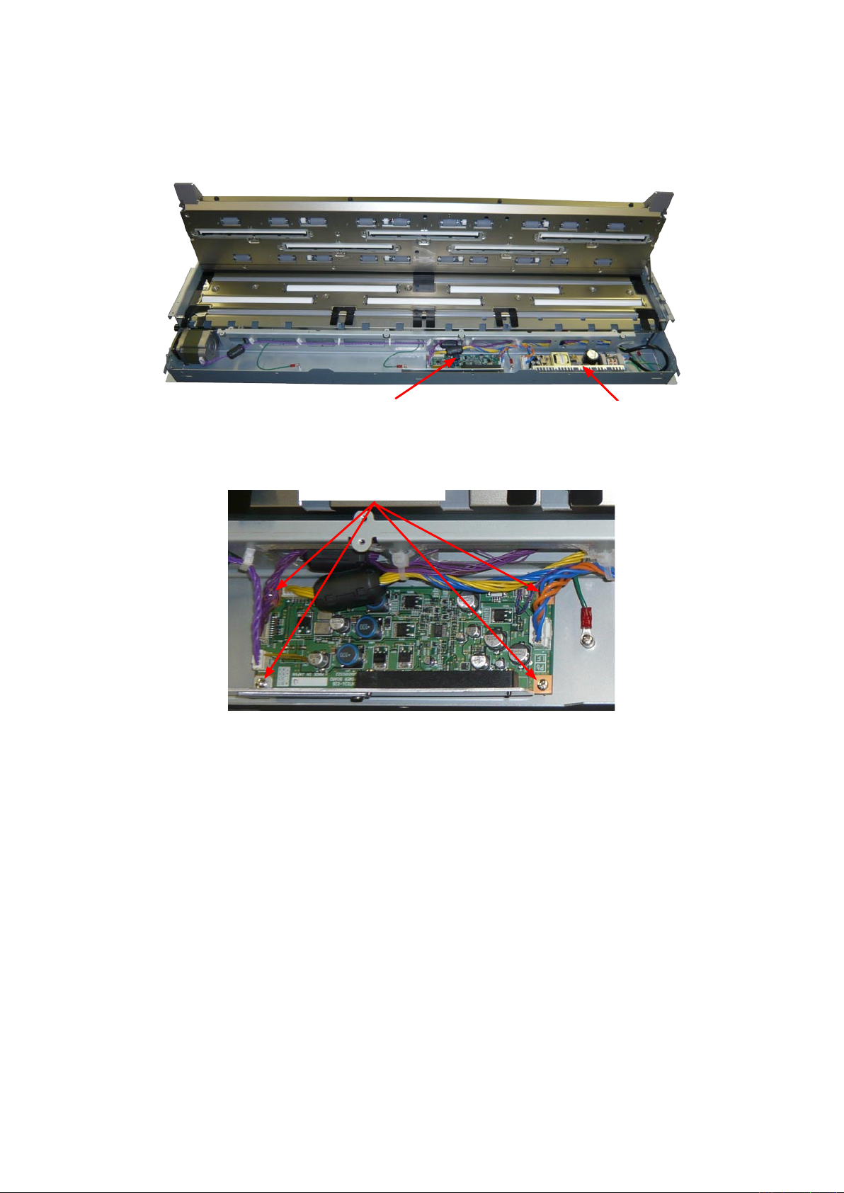
8.19 CIS Power Board
Detaching the CIS power board
(1) Detach the top, front, left side and right side covers (see Sections 8.1, 8.2, 8.3 and 8.4).
CIS power board
(2) Disconnect all the connectors on the CIS power board and remove the four M3L6 binding head screws
holding the CIS power board.
M3L6 binding head screw
(3) Detach the CIS power board from the unit.
Power supply board
Reattaching the CIS power board
(1) Reattach the CIS power board in the reverse order in which it was detached.
CSX300-UM-251-9370 8-24
Page 73
8. DISASSEMBLING AND ADJUSTING THE MECHANICAL PARTS
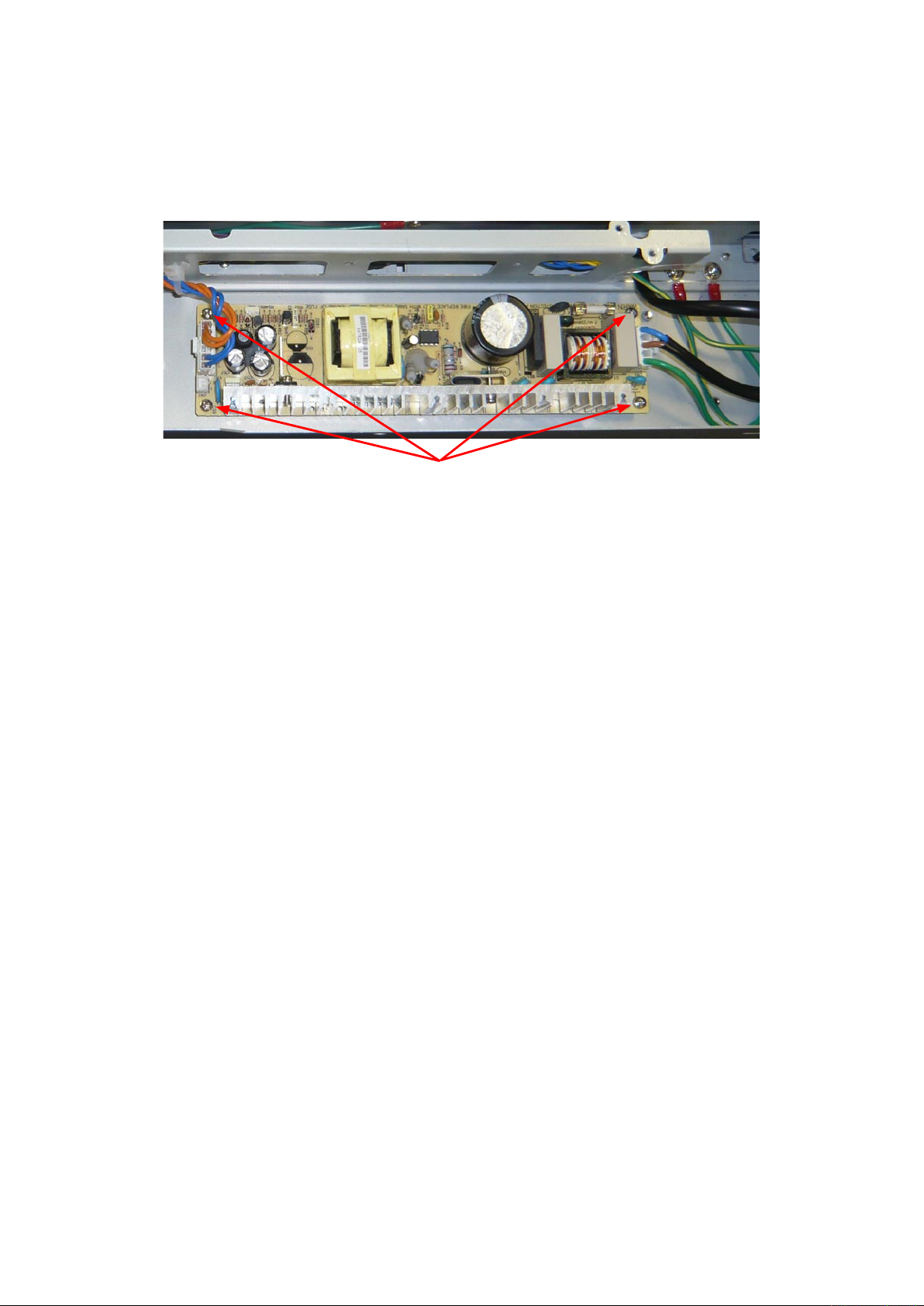
8.20 Switching Power Supply Board
Detaching the switching power supply board
(1) Detach the top, front, left side and right side covers (see Sections 8.1, 8.2, 8.3 and 8.4).
(2) Remove the four M3L6 binding head screws holding the switching power supply board.
M3L6 binding head screw
(4) Disconnect all the connectors on the switching power supply board.
(5) Detach the switching power supply board from the unit.
Reattaching the switching power supply board
(1) Reattach the switching power supply board in the reverse order in which it was detached.
CSX300-UM-251-9370 8-25
Page 74

8. DISASSEMBLING AND ADJUSTING THE MECHANICAL PARTS
8.21 Feed Motor
Detaching the feed motor
(1) Detach the top, front, left side and right side covers (see Sections 8.1, 8.2, 8.3 and 8.4).
(2) Detach the feed drive belt (see Section 8.7).
(3) Remove the two M4L8 pan head screws with washer holding the feed motor.
M4L8 pan head screw with washer
(4) Disconnect the cable from the feed motor.
Feed motor
Feed motor cable
Reattaching the feed motor
(1) Reattach the feed motor in the reverse order in which it was detached.
(2) Perform the calibration and the software adjustment if the feed motor was replaced or detached.
CSX300-UM-251-9370 8-26
Page 75

9. ADJUSTMENTS USING THE SOFTWARE
9. ADJUSTMENTS USING THE SOFTWARE
9.1 Starting the Software
• Ensure that OPS112 (Scanning Master 21+ Ver 6.60 or later) is installed.
(1) Connect the scanner to the PC using a USB cable and turn it on.
(2) Start Windows (OS).
(3) Run the Scanning Master 21+ (OPS112) from the Start.
(4) Select "Model Setup" from the "Scan" menu.
(5) Select "CSX300-09" from the pull down menu.
(6) Click the "Confirm" button to confirm the scanner is connected.
CSX300-UM-251-9370 9-1
Page 76

9. ADJUSTMENTS USING THE SOFTWARE
(7) The following message is displayed when the scanner is detected.
Click "OK" button.
(8) Select "About" from the "Help" menu.
(9) Click the scanner icon while pressing and holding down the "Ctrl" key.
Next, click the "OK" button while pressing and holding down the "Shift" key.
Icon
(10) Select "Adjust Scanner" from the "Tools" menu.
(11) Select "Yes".
CSX300-UM-251-9370 9-2
Page 77

9. ADJUSTMENTS USING THE SOFTWARE
(12) When you click the "OK" button in the following window, the Scanner Adjustment window will appear
with an Adjust menu.
CSX300-UM-251-9370 9-3
Page 78

9. ADJUSTMENTS USING THE SOFTWARE
9.2 Preparations before Making Adjustments
Note the current feed distance adjustment and position adjustment values while making adjustments.
This enables the values to be entered directly from the keyboard to restore the scanner to its previous status
if adjustment fails.
In main board replacement, the time required for adjustment can be reduced by setting the previously noted
feed distance adjustment and position adjustment values. However, for image sensor unit replacement, all
settings must be adjusted, eliminating the need to record the previous values.
Procedure to get the previous adjustment value
(1) Start the Scanning Master 21+ (see Section 9.1).
(2) Select "Adjust Feed Distance" from the "Adjust" menu.
(3) Click the "Current Value" button and note the value shown in the Feed Adjustment Value box. After
finishing, click the "Close" button.
(4) Similarly, select "Adjust Position" from the "Adjust" menu and click the "Current Value" button. Note the
values shown in the Origin, the X Overlap and Y Offset boxes and click the "Close" button.
CSX300-UM-251-9370 9-4
Page 79

9. ADJUSTMENTS USING THE SOFTWARE
CSX300 Adjustment Chart
Distances between two points Note measured distances below
C010-C090
A001
A002
A003
A004
A005
A006
A007
A008
A009
A010
A011
A008
A009
A010
A011
A008
A009
A010
A011
A008
A009
A010
A011
A012
A013
A014
A015
A016
A017
A018
A019
A020
A021
A018
A019
A020
A021
A018
A019
A020
A021
A018
A019
A020
A021
A022
A023
A024
A025
A026
A027
A028
A029
A030
A031
A028
A029
A030
A031
A028
A029
A030
A031
A028
A029
A030
A031
A032
A034
A035
A036
A037
A038
A039
A040
A041
A038
A039
A040
A041
A038
A039
A040
A041
A038
A039
A040
A041
A042
A043
A044
A045
A046
A047
A048
A049
A050
A051
A048
A049
A050
A051
A048
A049
A050
A051
A048
A049
A050
A051
A052
A053
A054
A055
A056
A057
A058
A059
A060
A061
A058
A059
A060
A061
A058
A059
A060
A061
A058
A059
A060
A061
A062
A063
A064
A065
A066
A067
A068
A069
A070
A071
A068
A069
A070
A071
A068
A069
A070
A071
A068
A069
A070
A071
A072
A073
A074
A075
A076
A077
A078
A079
A080
A081
A078
A079
A080
A081
A078
A079
A080
A081
A078
A079
A080
A081
A082
A083
A084
A085
A086
A088
A087
A089
A090
A091
A088
A089
A090
A091
A088
A089
A090
A091
A088
A089
A090
A091
A092
A093
A094
A095
A096
A097
A098
A099
A100
A101
A098
A099
A100
A101
A098
A099
A100
A101
A098
A099
A100
A101
A102
A103
A104
A105
A106
A107
A108
A109
A110
A111
A108
A109
A110
A111
A108
A109
A110
A111
A108
A109
A110
A111
A112
A113
A114
A115
A116
A117
A033
A001
A002
A003
A004
A005
A006
A007
A008
A009
A010
A011
A012
A013
A014
A015
A016
A017
A018
A019
A020
A021
A022
A023
A024
A025
A026
A027
A028
A029
A030
A031
A032
A034
A035
A036
A037
A038
A039
A040
A041
A042
A043
A044
A045
A046
A047
A048
A049
A050
A051
A052
A053
A054
A055
A056
A057
A058
A059
A060
A061
A062
A063
A064
A065
A066
A067
A068
A069
A070
A071
A072
A073
A074
A075
A076
A077
A078
A079
A080
A081
A082
A083
A084
A085
A086
A088
A087
A089
A090
A091
A092
A093
A094
A095
A096
A097
A098
A099
A100
A101
A102
A103
A104
A105
A106
A107
A108
A109
A110
A111
A112
A113
A114
A115
A116
A117
A033
B001
B002
B003
B004
B005
B006
B007
B008
B009
B010
B011
B008
B009
B010
B011
B008
B009
B010
B011
B008
B009
B010
B011
B012
B013
B014
B015
B016
B017
B018
B019
B020
B021
B018
B019
B020
B021
B018
B019
B020
B021
B018
B019
B020
B021
B022
B023
B024
B025
B026
B027
B028
B029
B030
B031
B028
B029
B030
B031
B028
B029
B030
B031
B028
B029
B030
B031
B032
B034
B035
B036
B037
B038
B039
B040
B041
B038
B039
B040
B041
B038
B039
B040
B041
B038
B039
B040
B041
B042
B043
B044
B045
B046
B047
B048
B049
B050
B051
B048
B049
B050
B051
B048
B049
B050
B051
B048
B049
B050
B051
B052
B053
B054
B055
B056
B057
B058
B059
B060
B061
B058
B059
B060
B061
B058
B059
B060
B061
B058
B059
B060
B061
B062
B063
B064
B065
B066
B067
B068
B069
B070
B071
B068
B069
B070
B071
B068
B069
B070
B071
B068
B069
B070
B071
B072
B073
B074
B075
B076
B077
B078
B079
B080
B081
B078
B079
B080
B081
B078
B079
B080
B081
B078
B079
B080
B081
B082
B083
B084
B085
B086
B088
B087
B089
B090
B091
B088
B089
B090
B091
B088
B089
B090
B091
B088
B089
B090
B091
B092
B093
B094
B095
B096
B097
B098
B099
B100
B101
B098
B099
B100
B101
B098
B099
B100
B101
B098
B099
B100
B101
B102
B103
B104
B105
B106
B107
B108
B109
B110
B111
B108
B109
B110
B111
B108
B109
B110
B111
B108
B109
B110
B111
B112
B113
B114
B115
B116
B117
B033
B001
B002
B003
B004
B005
B006
B007
B008
B009
B010
B011
B012
B013
B014
B015
B016
B017
B018
B019
B020
B021
B022
B023
B024
B025
B026
B027
B028
B029
B030
B031
B032
B034
B035
B036
B037
B038
B039
B040
B041
B042
B043
B044
B045
B046
B047
B048
B049
B050
B051
B052
B053
B054
B055
B056
B057
B058
B059
B060
B061
B062
B063
B064
B065
B066
B067
B068
B069
B070
B071
B072
B073
B074
B075
B076
B077
B078
B079
B080
B081
B082
B083
B084
B085
B086
B088
B087
B089
B090
B091
B092
B093
B094
B095
B096
B097
B098
B099
B100
B101
B102
B103
B104
B105
B106
B107
B108
B109
B110
B111
B112
B113
B114
B115
B116
B117
B033
D001
D002
D003
D004
D005
D006
D007
D008
D009
D010
D011
D008
D009
D010
D011
D008
D009
D010
D011
D008
D009
D010
D011
D012
D013
D014
D015
D016
D017
D018
D019
D020
D021
D018
D019
D020
D021
D018
D019
D020
D021
D018
D019
D020
D021
D022
D023
D024
D025
D026
D027
D028
D029
D030
D031
D028
D029
D030
D031
D028
D029
D030
D031
D028
D029
D030
D031
D032
D034
D035
D036
D037
D038
D039
D040
D041
D038
D039
D040
D041
D038
D039
D040
D041
D038
D039
D040
D041
D042
D043
D044
D045
D046
D047
D048
D049
D050
D051
D048
D049
D050
D051
D048
D049
D050
D051
D048
D049
D050
D051
D052
D053
D054
D055
D056
D057
D058
D059
D060
D061
D058
D059
D060
D061
D058
D059
D060
D061
D058
D059
D060
D061
D062
D063
D064
D065
D066
D067
D068
D069
D070
D071
D068
D069
D070
D071
D068
D069
D070
D071
D068
D069
D070
D071
D072
D073
D074
D075
D076
D077
D078
D079
D080
D081
D078
D079
D080
D081
D078
D079
D080
D081
D078
D079
D080
D081
D082
D083
D084
D085
D086
D088
D087
D089
D090
D091
D088
D089
D090
D091
D088
D089
D090
D091
D088
D089
D090
D091
D092
D093
D094
D095
D096
D097
D098
D099
D100
D101
D098
D099
D100
D101
D098
D099
D100
D101
D098
D099
D100
D101
D102
D103
D104
D105
D106
D107
D108
D109
D110
D111
D108
D109
D110
D111
D108
D109
D110
D111
D108
D109
D110
D111
D112
D113
D114
D115
D116
D117
D033
D001
D002
D003
D004
D005
D006
D007
D008
D009
D010
D011
D012
D013
D014
D015
D016
D017
D018
D019
D020
D021
D022
D023
D024
D025
D026
D027
D028
D029
D030
D031
D032
D034
D035
D036
D037
D038
D039
D040
D041
D042
D043
D044
D045
D046
D047
D048
D049
D050
D051
D052
D053
D054
D055
D056
D057
D058
D059
D060
D061
D062
D063
D064
D065
D066
D067
D068
D069
D070
D071
D072
D073
D074
D075
D076
D077
D078
D079
D080
D081
D082
D083
D084
D085
D086
D088
D087
D089
D090
D091
D092
D093
D094
D095
D096
D097
D098
D099
D100
D101
D102
D103
D104
D105
D106
D107
D108
D109
D110
D111
D112
D113
D114
D115
D116
D117
D033
E001
E002
E003
E004
E005
E006
E007
E008
E009
E010
E011
E008
E009
E010
E011
E008
E009
E010
E011
E008
E009
E010
E011
E012
E013
E014
E015
E016
E017
E018
E019
E020
E021
E018
E019
E020
E021
E018
E019
E020
E021
E018
E019
E020
E021
E022
E023
E024
E025
E026
E027
E028
E029
E030
E031
E028
E029
E030
E031
E028
E029
E030
E031
E028
E029
E030
E031
E032
E034
E035
E036
E037
E038
E039
E040
E041
E038
E039
E040
E041
E038
E039
E040
E041
E038
E039
E040
E041
E042
E043
E044
E045
E046
E047
E048
E049
E050
E051
E048
E049
E050
E051
E048
E049
E050
E051
E048
E049
E050
E051
E052
E053
E054
E055
E056
E057
E058
E059
E060
E061
E058
E059
E060
E061
E058
E059
E060
E061
E058
E059
E060
E061
E062
E063
E064
E065
E066
E067
E068
E069
E070
E071
E068
E069
E070
E071
E068
E069
E070
E071
E068
E069
E070
E071
E072
E073
E074
E075
E076
E077
E078
E079
E080
E081
E078
E079
E080
E081
E078
E079
E080
E081
E078
E079
E080
E081
E082
E083
E084
E085
E086
E088
E087
E089
E090
E091
E088
E089
E090
E091
E088
E089
E090
E091
E088
E089
E090
E091
E092
E093
E094
E095
E096
E097
E098
E099
E100
E101
E098
E099
E100
E101
E098
E099
E100
E101
E098
E099
E100
E101
E102
E103
E104
E105
E106
E107
E108
E109
E110
E111
E108
E109
E110
E111
E108
E109
E110
E111
E108
E109
E110
E111
E112
E113
E114
E115
E116
E117
E033
E001
E002
E003
E004
E005
E006
E007
E008
E009
E010
E011
E012
E013
E014
E015
E016
E017
E018
E019
E020
E021
E022
E023
E024
E025
E026
E027
E028
E029
E030
E031
E032
E034
E035
E036
E037
E038
E039
E040
E041
E042
E043
E044
E045
E046
E047
E048
E049
E050
E051
E052
E053
E054
E055
E056
E057
E058
E059
E060
E061
E062
E063
E064
E065
E066
E067
E068
E069
E070
E071
E072
E073
E074
E075
E076
E077
E078
E079
E080
E081
E082
E083
E084
E085
E086
E088
E087
E089
E090
E091
E092
E093
E094
E095
E096
E097
E098
E099
E100
E101
E102
E103
E104
E105
E106
E107
E108
E109
E110
E111
E112
E113
E114
E115
E116
E117
E033
C001
C002
C003
C004
C005
C006
C007
C008
C009
C010
C011
C012
C013
C014
C015
C016
C017
C018
C019
C020
C021
C022
C023
C024
C025
C026
C027
C028
C029
C030
C031
C032
C034
C035
C036
C037
C038
C039
C040
C041
C042
C043
C044
C045
C046
C047
C048
C049
C050
C051
C052
C053
C054
C055
C056
C057
C058
C059
C060
C061
C062
C063
C064
C065
C066
C067
C068
C069
C070
C071
C072
C073
C074
C075
C076
C077
C078
C079
C080
C081
C082
C083
C084
C085
C086
C088
C087
C089
C090
C091
C092
C093
C094
C095
C096
C097
C098
C099
C100
C101
C102
C103
C104
C105
C106
C107
C108
C109
C110
C111
C112
C113
C114
C115
C116
C117
C033
A0
A1
24
A1
A2
18
A2
A3
12
A3
A4
9
A4
A4
9
A4
A3
12
A3
A2
18
A1
A2
24
A0
A1
C010
C090
7
8
9
6
5
4
3
2
1
7
8
9
6
5
4
3
2
1
7
8
9
6
5
4
3
2
1
7
8
9
6
5
4
3
2
1
7
8
9
6
5
4
3
2
1
7
8
9
6
5
4
3
2
1
7
8
9
6
5
4
3
2
1
7
8
9
6
5
4
3
2
1
7
8
9
6
5
4
3
2
1
7
8
9
6
5
4
3
2
1
7
8
9
6
5
4
3
2
1
7
8
9
6
5
4
3
2
1
7
8
9
6
5
4
3
2
1
7
8
9
6
5
4
3
2
1
7
8
9
6
5
4
3
2
1
7
8
9
6
5
4
3
2
1
7
8
9
6
5
4
3
2
1
7
8
9
6
5
4
3
2
1
7
8
9
6
5
4
3
2
1
7
8
9
6
5
4
3
2
1
7
8
9
6
5
4
3
2
1
7
8
9
6
5
4
3
2
1
7
8
9
6
5
4
3
2
1
7
8
9
6
5
4
3
2
1
7
8
9
6
5
4
3
2
1
7
8
9
6
5
4
3
2
1
7
8
9
6
5
4
3
2
1
7
8
9
6
5
4
3
2
1
7
8
9
6
5
4
3
2
1
7
8
9
6
5
4
3
2
1
7
8
9
6
5
4
3
2
1
7
8
9
6
5
4
3
2
1
7
8
9
6
5
4
3
2
1
7
8
9
6
5
4
3
2
1
7
8
9
6
5
4
3
2
1
7
8
9
6
5
4
3
2
1
7
8
9
6
5
4
3
2
1
7
8
9
6
5
4
3
2
1
7
8
9
6
5
4
3
2
1
7
8
9
6
5
4
3
2
1
7
8
9
6
5
4
3
2
1
7
8
9
6
5
4
3
2
1
7
8
9
6
5
4
3
2
1
7
8
9
6
5
4
3
2
1
7
8
9
6
5
4
3
2
1
7
8
9
6
5
4
3
2
1
7
8
9
6
5
4
3
2
1
7
8
9
6
5
4
3
2
1
7
8
9
6
5
4
3
2
1
7
8
9
6
5
4
3
2
1
7
8
9
6
5
4
3
2
1
7
8
9
6
5
4
3
2
1
7
8
9
6
5
4
3
2
1
7
8
9
6
5
4
3
2
1
7
8
9
6
5
4
3
2
1
7
8
9
6
5
4
3
2
1
7
8
9
6
5
4
3
2
1
7
8
9
6
5
4
3
2
1
7
8
9
6
5
4
3
2
1
7
8
9
6
5
4
3
2
1
7
8
9
6
5
4
3
2
1
7
8
9
6
5
4
3
2
1
7
8
9
6
5
4
3
2
1
7
8
9
6
5
4
3
2
1
7
8
9
6
5
4
3
2
1
7
8
9
6
5
4
3
2
1
7
8
9
6
5
4
3
2
1
7
8
9
6
5
4
3
2
1
7
8
9
6
5
4
3
2
1
7
8
9
6
5
4
3
2
1
7
8
9
6
5
4
3
2
1
7
8
9
6
5
4
3
2
1
7
8
9
6
5
4
3
2
2
1
7
8
6
5
4
3
7
8
9
6
5
4
3
2
1
7
8
9
6
5
4
3
2
1
7
8
9
6
5
4
3
2
1
7
8
9
6
5
4
3
2
1
7
8
9
6
5
4
3
2
1
7
8
9
6
5
4
3
2
1
7
8
9
6
5
4
3
2
1
7
8
9
6
5
4
3
2
1
7
8
9
6
5
4
3
2
1
7
8
9
6
5
4
3
2
1
7
8
9
6
5
4
3
2
1
7
8
9
6
5
4
3
2
1
7
8
9
6
5
4
3
2
1
7
8
9
6
5
4
3
2
1
7
8
9
6
5
4
3
2
1
7
8
9
6
5
4
3
2
1
7
8
9
6
5
4
3
2
1
7
8
9
6
5
4
3
2
1
7
8
9
6
5
4
3
2
1
7
8
9
6
5
4
3
2
1
7
8
9
6
5
4
3
2
1
7
8
9
6
5
4
3
2
1
7
8
9
6
5
4
3
2
1
7
8
9
6
5
4
3
2
1
7
8
9
6
5
4
3
2
1
7
8
9
6
5
4
3
2
1
7
8
9
6
5
4
3
2
1
7
8
9
6
5
4
3
2
1
7
8
9
6
5
4
3
2
1
7
8
9
6
5
4
3
2
1
7
8
9
6
5
4
3
2
1
7
8
9
6
5
4
3
2
1
7
8
9
6
5
4
3
2
1
7
8
9
6
5
4
3
2
1
7
8
9
6
5
3
2
1
7
8
9
6
5
4
4
3
2
1
1 1
7
8
6
5
4
3
2
7
8
9
6
5
4
3
2
1
7
8
9
6
5
4
3
2
1
7
8
9
6
5
4
3
2
1
7
8
9
6
5
4
3
2
1
7
8
9
6
5
4
3
2
1
7
8
9
6
5
4
3
2
1
7
8
9
6
5
4
3
2
1
7
8
9
6
5
4
3
2
1
7
8
9
6
5
4
3
2
1
7
8
9
6
5
4
3
2
1
7
8
9
6
5
4
3
2
1
7
8
9
6
5
4
3
2
1
7
8
9
6
5
4
3
2
1
7
8
9
6
5
4
3
2
1
7
8
9
6
5
4
3
2
1
7
8
9
6
5
4
3
2
1
7
8
9
6
5
4
3
2
1
7
8
9
6
5
4
3
2
1
7
8
9
6
5
4
3
2
1
7
8
9
6
5
4
3
2
1
7
8
9
6
5
4
3
2
1
7
8
9
6
5
4
3
2
1
7
8
9
6
5
4
3
2
1
7
8
9
6
5
4
3
2
1
7
8
9
6
5
4
3
2
1
7
8
9
6
5
4
3
2
1
7
8
9
6
5
4
3
2
1
7
8
9
6
5
4
3
2
1
7
8
9
6
5
4
3
2
1
7
8
9
6
5
4
3
2
1
7
8
9
6
5
4
3
2
1
7
8
9
6
5
4
3
2
1
7
8
9
6
5
4
3
2
1
7
8
9
6
5
4
3
2
1
7
8
9
6
5
4
3
2
1
7
8
9
6
5
4
3
2
1
7
8
9
6
5
4
3
2
1
Cut along this dotted line Cut along this dotted line Cut along this dotted lineCut along this dotted line
641711400 071025
A0
A1
24
A1
A2
18
A2
A3
12
A3
A4
9
A4
A4
9
A3
A4
12
A2
A3
18A1
A2
24
A0
A1
9.3 Preparing Adjustment Charts
There are the three kind of adjustment charts.
• Calibration Sheet: This sheet is used for the sensor sensitivity adjustment (White
and black sheet, Standard accessory).
• CSX300 adjustment test chart: This chart is used for the manual sensor stitch adjustment,
the feed distance adjustment and the scanning start position
adjustment.
• Auto sensor stitch adjustment chart: This chart is used for the auto sensor stitch adjustment.
CSX300-UM-251-9370 9-5
Page 80
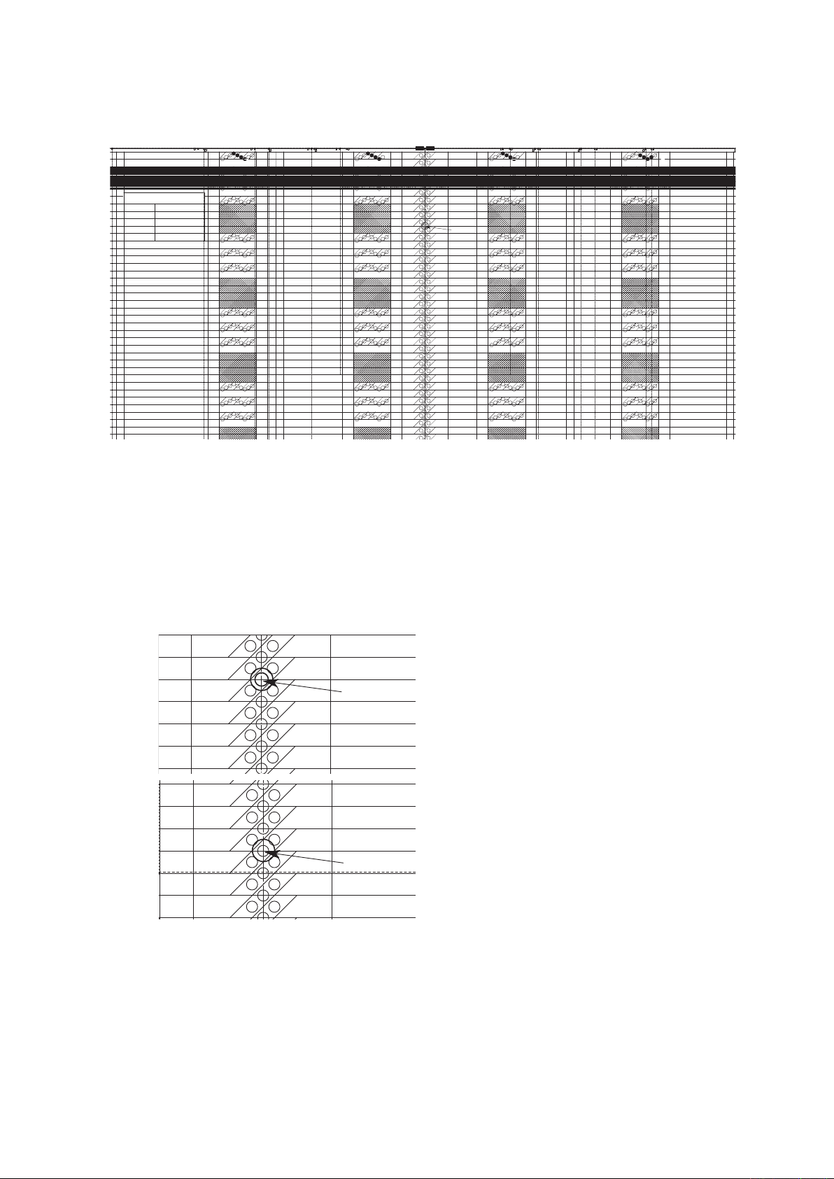
CSX300 Adjustment Chart
Distances between two points Note measured distances below
C010-C090
A001
A002
A003
A004
A005
A006
A007
A008
A009
A010
A011
A008
A009
A010
A011
A008
A009
A010
A011
A008
A009
A010
A011
A012
A013
A014
A015
A016
A017
A018
A019
A020
A021
A018
A019
A020
A021
A018
A019
A020
A021
A018
A019
A020
A021
A022
A023
A024
A025
A026
A027
A028
A029
A030
A031
A028
A029
A030
A031
A028
A029
A030
A031
A028
A029
A030
A031
A032
A034
A035
A036
A037
A038
A038
A038
A038
A033
A001
A002
A003
A004
A005
A006
A007
A008
A009
A010
A011
A012
A013
A014
A015
A016
A017
A018
A019
A020
A021
A022
A023
A024
A025
A026
A027
A028
A029
A030
A031
A032
A034
A035
A036
A037
A038
A033
B001
B002
B003
B004
B005
B006
B007
B008
B009
B010
B011
B008
B009
B010
B011
B008
B009
B010
B011
B008
B009
B010
B011
B012
B013
B014
B015
B016
B017
B018
B019
B020
B021
B018
B019
B020
B021
B018
B019
B020
B021
B018
B019
B020
B021
B022
B023
B024
B025
B026
B027
B028
B029
B030
B031
B028
B029
B030
B031
B028
B029
B030
B031
B028
B029
B030
B031
B032
B034
B035
B036
B037
B038
B038
B038
B038
B033
B001
B002
B003
B004
B005
B006
B007
B008
B009
B010
B011
B012
B013
B014
B015
B016
B017
B018
B019
B020
B021
B022
B023
B024
B025
B026
B027
B028
B029
B030
B031
B032
B034
B035
B036
B037
B038
B033
D001
D002
D003
D004
D005
D006
D007
D008
D009
D010
D011
D008
D009
D010
D011
D008
D009
D010
D011
D008
D009
D010
D011
D012
D013
D014
D015
D016
D017
D018
D019
D020
D021
D018
D019
D020
D021
D018
D019
D020
D021
D018
D019
D020
D021
D022
D023
D024
D025
D026
D027
D028
D029
D030
D031
D028
D029
D030
D031
D028
D029
D030
D031
D028
D029
D030
D031
D032
D034
D035
D036
D037
D038
D038
D038
D038
D033
D001
D002
D003
D004
D005
D006
D007
D008
D009
D010
D011
D012
D013
D014
D015
D016
D017
D018
D019
D020
D021
D022
D023
D024
D025
D026
D027
D028
D029
D030
D031
D032
D034
D035
D036
D037
D038
D033
E001
E002
E003
E004
E005
E006
E007
E008
E009
E010
E011
E008
E009
E010
E011
E008
E009
E010
E011
E008
E009
E010
E011
E012
E013
E014
E015
E016
E017
E018
E019
E020
E021
E018
E019
E020
E021
E018
E019
E020
E021
E018
E019
E020
E021
E022
E023
E024
E025
E026
E027
E028
E029
E030
E031
E028
E029
E030
E031
E028
E029
E030
E031
E028
E029
E030
E031
E032
E034
E035
E036
E037
E038
E038
E038
E038
E033
E001
E002
E003
E004
E005
E006
E007
E008
E009
E010
E011
E012
E013
E014
E015
E016
E017
E018
E019
E020
E021
E022
E023
E024
E025
E026
E027
E028
E029
E030
E031
E032
E034
E035
E036
E037
E038
E033
C001
C002
C003
C004
C005
C006
C007
C008
C009
C010
C011
C012
C013
C014
C015
C016
C017
C018
C019
C020
C021
C022
C023
C024
C025
C026
C027
C028
C029
C030
C031
C032
C034
C035
C036
C037
C038
C033
C001
C002
C003
C004
C005
C006
C007
C008
C009
C010
C011
C012
C013
C014
C015
C016
C017
C018
C019
C020
C021
C022
C023
C024
C025
C026
C027
C028
C029
C030
C031
C032
C034
C035
C036
C037
C038
C033
A0
A1
24
A1
A2
18
A2
A3
12
A3
A4
9
A4
A4
9
A4
A3
12
A3
A2
18
A1
A2
24
C010
7
8
9
6
5
4
3
2
1
7
8
9
6
5
4
3
2
1
7
8
9
6
5
4
3
2
1
7
8
9
6
5
4
3
2
1
7
8
9
6
5
4
3
2
1
7
8
9
6
5
4
3
2
1
7
8
9
6
5
4
3
2
1
7
8
9
6
5
4
3
2
1
7
8
9
6
5
4
3
2
1
7
8
9
6
5
4
3
2
1
7
8
9
6
5
4
3
2
1
7
8
9
6
5
4
3
2
1
7
8
9
6
5
4
3
2
1
7
8
9
6
5
4
3
2
1
7
8
9
6
5
4
3
2
1
7
8
9
6
5
4
3
2
1
7
8
9
6
5
4
3
2
1
7
8
9
6
5
4
3
2
1
7
8
9
6
5
4
3
2
1
7
8
9
6
5
4
3
2
1
7
8
9
6
5
4
3
2
1
7
8
9
6
5
4
3
2
1
7
8
9
6
5
4
3
2
1
7
8
9
6
5
4
3
2
1
7
8
9
6
5
4
3
2
2
1
7
8
6
5
4
3
7
8
9
6
5
4
3
2
1
7
8
9
6
5
4
3
2
1
7
8
9
6
5
4
3
2
1
7
8
9
6
5
4
3
2
1
7
8
9
6
5
4
3
2
1
7
8
9
6
5
4
3
2
1
7
8
9
6
5
4
3
2
1
7
8
9
6
5
4
3
2
1
7
8
9
6
5
4
3
2
1
7
8
9
6
5
4
3
2
1
7
8
9
6
5
3
2
1
7
8
9
6
5
4
4
3
2
1
1 1
7
8
6
5
4
3
2
7
8
9
6
5
4
3
2
1
7
8
9
6
5
4
3
2
1
7
8
9
6
5
4
3
2
1
7
8
9
6
5
4
3
2
1
7
8
9
6
5
4
3
2
1
7
8
9
6
5
4
3
2
1
7
8
9
6
5
4
3
2
1
7
8
9
6
5
4
3
2
1
7
8
9
6
5
4
3
2
1
7
8
9
6
5
4
3
2
1
7
8
9
6
5
4
3
2
1
7
8
9
6
5
4
3
2
1
7
8
9
6
5
4
3
2
1
Cut along this dotted line Cut along this dotted line Cut along this dotted lineCut along this dotted line
B001
B002
B003
B004
B005
B006
B007
B008
B009
B010
B011
B012
B013
B014
D001
D002
D003
D004
D005
D006
D007
D008
D009
D010
D011
D008
D009
D010
D011
D008
D009
D010
D011
D008
D009
D010
D011
D012
D013
D014
D001
D002
D003
D004
D005
D006
D007
D008
D009
D010
D011
D012
D013
D014
E001
E002
E003
E004
E005
E006
E007
E008
E009
E010
E011
E008
E009
E010
E011
E008
E009
E010
E011
E008
E009
E010
E011
E012
E013
E014
E001
E002
E003
E004
E005
E006
E007
E008
E009
E010
E011
E012
E013
E014
C001
C002
C003
C004
C005
C006
C007
C008
C009
C010
C011
C012
C013
C014
C001
C002
C003
C004
C005
C006
C007
C008
C009
C010
C011
C012
C013
C014
24
A1
A2
18
A2
A3
12
A3
A4
9
A4
C010
7
8
9
6
5
4
3
2
1
7
8
9
6
5
4
3
2
1
7
8
9
6
5
4
3
2
1
7
8
9
6
5
4
3
2
1
7
8
9
6
5
4
3
2
1
7
8
9
6
5
4
3
2
1
7
8
9
6
5
4
3
2
1
7
8
9
6
5
4
3
2
1
7
8
9
6
5
4
3
2
1
7
8
9
6
5
4
3
2
1
7
8
9
6
5
4
3
2
2
1
7
8
6
5
4
3
B041
B042
B043
B044
B045
B046
B047
B048
B049
B050
B051
B052
B053
B054
B055
B056
B057
B058
B059
B060
B061
B062
B063
B064
B065
B066
B067
B068
B069
B070
B071
B072
B073
B074
B075
B076
B077
B078
B079
B080
B081
B082
B083
B084
B085
B086
B088
B087
B089
B090
B091
B092
B093
D041
D041
D041
D041
D042
D043
D044
D045
D046
D047
D048
D049
D050
D051
D048
D049
D050
D051
D048
D049
D050
D051
D048
D049
D050
D051
D052
D053
D054
D055
D056
D057
D058
D059
D060
D061
D058
D059
D060
D061
D058
D059
D060
D061
D058
D059
D060
D061
D062
D063
D064
D065
D066
D067
D068
D069
D070
D071
D068
D069
D070
D071
D068
D069
D070
D071
D068
D069
D070
D071
D072
D073
D074
D075
D076
D077
D078
D079
D080
D081
D078
D079
D080
D081
D078
D079
D080
D081
D078
D079
D080
D081
D082
D083
D084
D085
D086
D088
D087
D089
D090
D091
D088
D089
D090
D091
D088
D089
D090
D091
D088
D089
D090
D091
D092
D093
D041
D042
D043
D044
D045
D046
D047
D048
D049
D050
D051
D052
D053
D054
D055
D056
D057
D058
D059
D060
D061
D062
D063
D064
D065
D066
D067
D068
D069
D070
D071
D072
D073
D074
D075
D076
D077
D078
D079
D080
D081
D082
D083
D084
D085
D086
D088
D087
D089
D090
D091
D092
D093
E041
E041
E041
E041
E042
E043
E044
E045
E046
E047
E048
E049
E050
E051
E048
E049
E050
E051
E048
E049
E050
E051
E048
E049
E050
E051
E052
E053
E054
E055
E056
E057
E058
E059
E060
E061
E058
E059
E060
E061
E058
E059
E060
E061
E058
E059
E060
E061
E062
E063
E064
E065
E066
E067
E068
E069
E070
E071
E068
E069
E070
E071
E068
E069
E070
E071
E068
E069
E070
E071
E072
E073
E074
E075
E076
E077
E078
E079
E080
E081
E078
E079
E080
E081
E078
E079
E080
E081
E078
E079
E080
E081
E082
E083
E084
E085
E086
E088
E087
E089
E090
E091
E088
E089
E090
E091
E088
E089
E090
E091
E088
E089
E090
E091
E092
E093
E041
E042
E043
E044
E045
E046
E047
E048
E049
E050
E051
E052
E053
E054
E055
E056
E057
E058
E059
E060
E061
E062
E063
E064
E065
E066
E067
E068
E069
E070
E071
E072
E073
E074
E075
E076
E077
E078
E079
E080
E081
E082
E083
E084
E085
E086
E088
E087
E089
E090
E091
E092
E093
C041
C042
C043
C044
C045
C046
C047
C048
C049
C050
C051
C052
C053
C054
C055
C056
C057
C058
C059
C060
C061
C062
C063
C064
C065
C066
C067
C068
C069
C070
C071
C072
C073
C074
C075
C076
C077
C078
C079
C080
C081
C082
C083
C084
C085
C086
C088
C087
C089
C090
C091
C092
C093
C041
C042
C043
C044
C045
C046
C047
C048
C049
C050
C051
C052
C053
C054
C055
C056
C057
C058
C059
C060
C061
C062
C063
C064
C065
C066
C067
C068
C069
C070
C071
C072
C073
C074
C075
C076
C077
C078
C079
C080
C081
C082
C083
C084
C085
C086
C088
C087
C089
C090
C091
C092
C093
C090
7
8
9
6
5
4
3
2
1
7
8
9
6
5
4
3
2
1
7
8
9
6
5
4
3
2
1
7
8
9
6
5
4
3
2
1
7
8
9
6
5
4
3
2
1
7
8
9
6
5
4
3
2
1
7
8
9
6
5
4
3
2
1
7
8
9
6
5
4
3
2
1
7
8
9
6
5
4
3
2
1
7
8
9
6
5
4
3
2
1
7
8
9
6
5
4
3
2
1
7
8
9
6
5
4
3
2
1
7
8
9
6
5
4
3
2
1
7
8
9
6
5
4
3
2
1
7
8
9
6
5
4
3
2
1
7
8
9
6
5
4
3
2
1
7
8
9
6
5
4
3
2
1
7
8
9
6
5
4
3
2
1
7
8
9
6
5
4
3
2
1
7
8
9
6
5
4
3
2
1
7
8
9
6
5
4
3
2
1
7
8
9
6
5
4
3
2
1
7
8
9
6
5
4
3
2
1
7
8
9
6
5
4
3
2
1
7
8
9
6
5
4
3
2
1
7
8
9
6
5
4
3
2
1
7
8
9
6
5
4
3
2
1
7
8
9
6
5
4
3
2
1
7
8
9
6
5
4
3
2
1
7
8
9
6
5
4
3
2
1
7
8
9
6
5
4
3
2
1
7
8
9
6
5
4
3
2
1
Preparing the CSX300 adjustment test chart
(1) Prepare a CSX300 adjustment test chart.
Print the Test Chart CSX300.pdf by the printer that is able to print A0 size.
(2) Make sure that the distances (measured with a glass scale) between the two points in all pairs are
<<Tip 1>> The test chart is made of Mylar paper.
For use in normal office environments (normal temperatures and humidity levels), you should
Make sure that each distance is measured with the utmost accuracy.
<<Tip 2>> Make sure that all staff members using this test chart select the same measurement points.
<<Tip 3>> If user-specified paper must be used for adjustments, you should make the measurements over
CSX300-UM-251-9370 9-6
included in the chart in advance. (See the chart shown above.)
only need to measure each distance once.
This chart has been designed with the assumption that the point shown below is used for
measurement.
as long a period of time as possible to obtain good results.
9. ADJUSTMENTS USING THE SOFTWARE
Page 81

9. ADJUSTMENTS USING THE SOFTWARE
9.4 Making Adjustments
When you replaced the main board or the CIS sensors, follow the sequence of adjustments below.
1. Calibration (white and black correction)
2. Feed distance adjustment
3. Sensor stitch alignment
4. Scanning start position adjustment
5. Recalibration (white and black correction)
Before beginning calibration, clean the contact glass plates and scanning-table surface. Any dust or dirt
on those surfaces may affect the calibration results and resulting image quality.
Check that the calibration sheet is free of any dust or dirt.
CSX300-UM-251-9370 9-7
Page 82
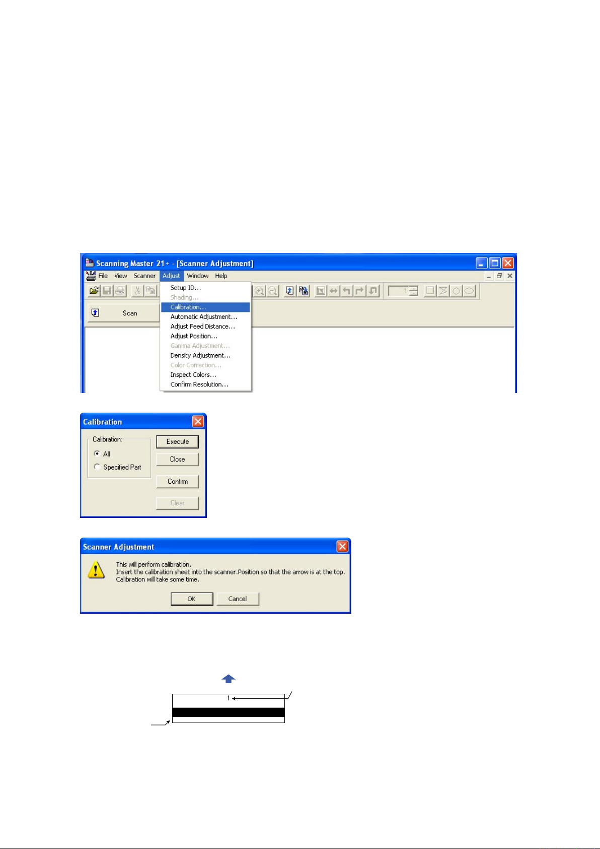
9. ADJUSTMENTS USING THE SOFTWARE
Calibration sheet
Arrow mark
Scanner
Insertion direction
9.4.1 Calibration (white and black correction)
In the following cases, perform this adjustment.
• When difference color appeared between each sensor.
• When you replaced the main board.
• When you replaced the CIS board.
• When you replaced or removed the CIS sensors.
• When you replaced or removed the contact glasses.
How to perform the calibration
(1) Connect the scanner to the computer. Turn on the power for the scanner then turn on power for the PC.
(2) Start Scanning Master 21+ (see Section 9.1).
(3) Clean the contact glass plate surfaces and the pinch rollers.
(4) Select "Calibration" from the "Adjust" menu.
(5) Select All in Calibration and click the Execute button.
(6) The following message is displayed.
Take out the white and black calibration sheet from its storage box.
Make sure that there is no dust on the calibration sheet.
Insert the calibration sheet into the scanner as instructed.
CSX300-UM-251-9370 9-8
Page 83
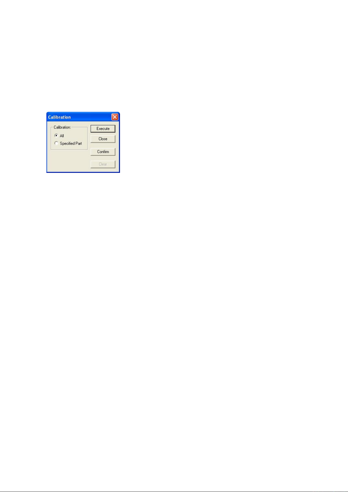
9. ADJUSTMENTS USING THE SOFTWARE
(7) Click the OK button to start scanning.
The scanned data is displayed when scanning is complete. Colors may differ slightly for individual
sensors to make it easier to identify problem areas in calibration. This does not indicate a defect.
Check that there are no vertical streaks, such as white patches, in the scanned data.
(Streaks occur when calibration is not performed correctly due to contamination by dust or dirt.)
(8) If the data is normal, calibration is complete.
Click the Close button and exit calibration mode.
(9) If any abnormal data is observed, specify the problem areas as follows:
Select Specified Part in Calibration.
(10) The mouse arrow cursor changes to a cross cursor when moved over the data. Click the left mouse
button with the mouse positioned over the streak data. The selected area is shown in blue. Repeat this
procedure for any additional streaks.
Areas that have been selected (shown in blue) can be deselected by clicking the left mouse button
again. To deselect all selected areas, click the Clear button.
(11) Once all required areas have been specified, remove the calibration sheet and clean the contact glass
plate, pinch roller and bottom of upper cover surfaces. Check the calibration sheet for dust and dirt, then
click the Execute button.
(12) Return to step (5) and verify the calibration results.
CSX300-UM-251-9370 9-9
Page 84
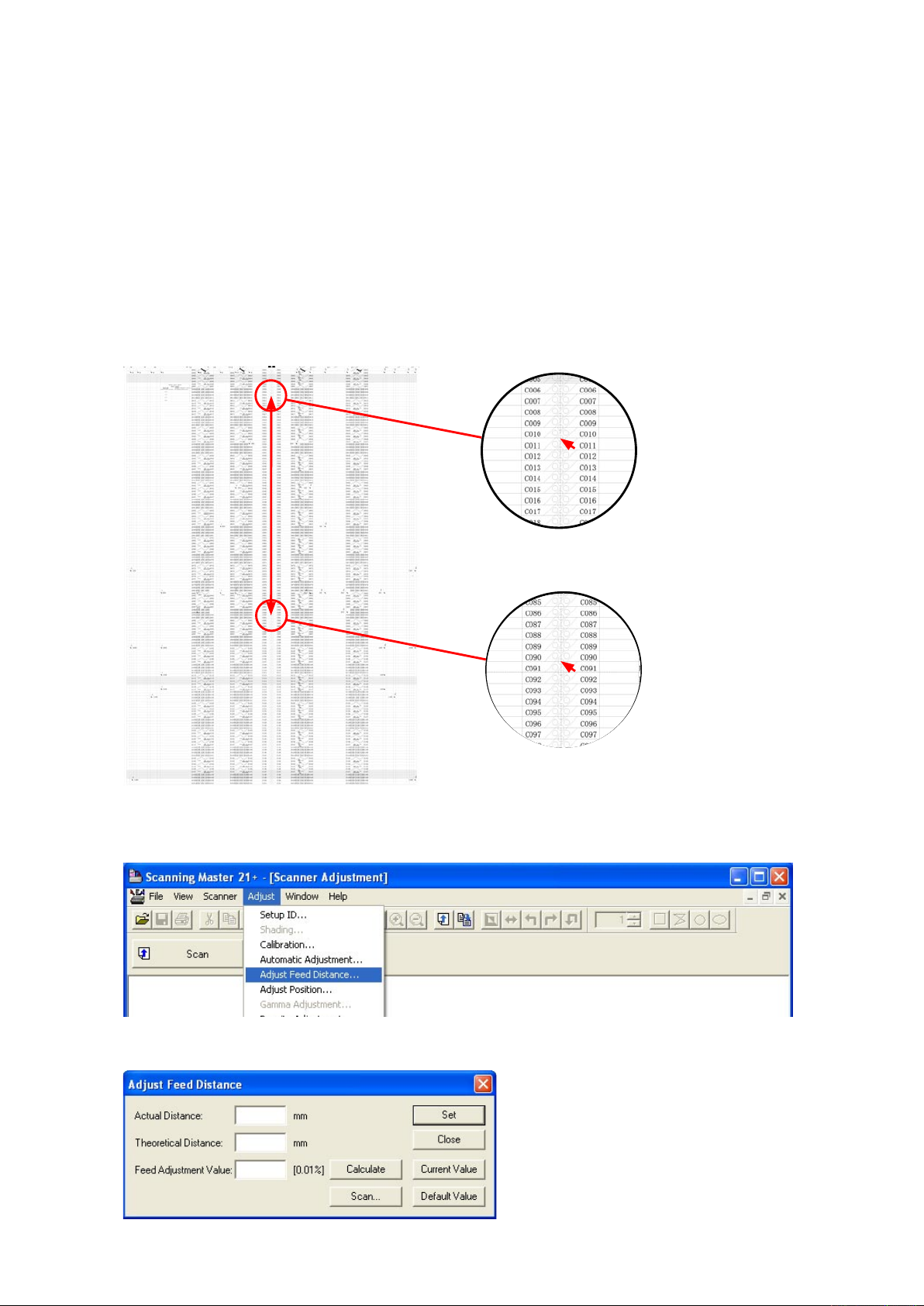
9. ADJUSTMENTS USING THE SOFTWARE
9.4.2 Feed distance adjustment
In the following cases, perform this adjustment.
• When the distance is different in the direction of the feed.
• When you replaced the main board.
• When you replaced or removed the CIS sensors.
• When you replaced or removed the feed motor.
• When you replaced or removed the feed rollers.
How to perform the feed distance adjustment
(1) Prepare the CSX300 Test Chart.
(2) Measure the distances between the C010 and the C090 points in the CSX300 Test Chart with a glass
scale. And then record it.
(3) Run the software. (See page 9-1) This is not necessary when the software is running already.
(4) Select "Adjust Feed Distance" from the "Adjust" menu.
(5) The following dialog box will appear. Correctly insert the CSX300 test chart to the scanner, and then
click the "Scan" button.
CSX300-UM-251-9370 9-10
Page 85
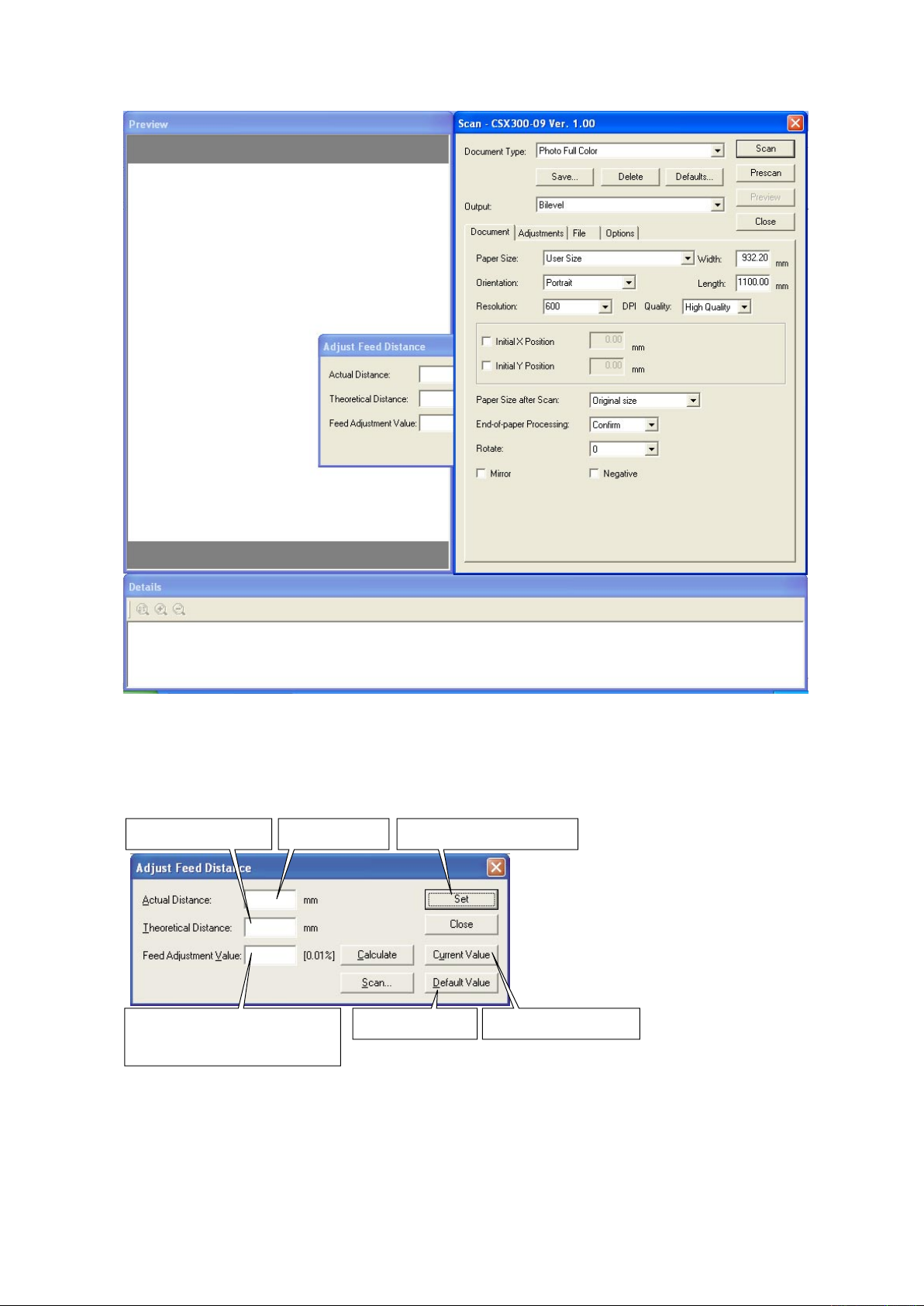
9. ADJUSTMENTS USING THE SOFTWARE
Measures the distance,
based on the scanned image
When actual and theoretical values appear
in their respective boxes, you can click the
Calculate button to calculate the feed.
The calculated feed will appear in this box.
Click this button to specify
the correction value for the scanner
.
Click this button to display
the value stored in the scanner
.
Click this button to
display the default value.
Type in the measured
distance here.
(6) The following dialog box will appear. Click the "Scan" button.
Select the following for "Document Info" and "Scan Settings":
"Document Info" Paper Size : User Size, Width: 932, Length 1100, Resolution: 600 dpi
Document Type : Photo Full Color
"Scan Settings" Output : Bilevel
The following dialog box appears, together with the scanned image.
CSX300-UM-251-9370 9-11
Page 86
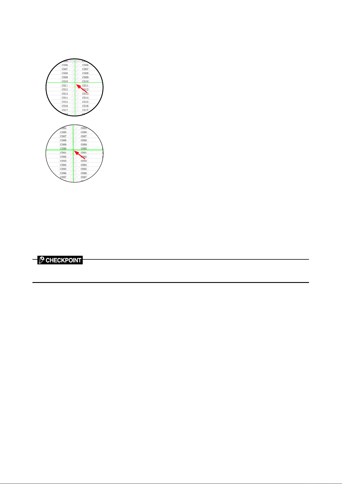
9. ADJUSTMENTS USING THE SOFTWARE
(8) Input the distance between C010 and C090 measured with a glass scale in the "Actual" box.
(9) Click anywhere within the "Theoretical" box and use the crosshairs cursor to click the white corner
indicated by arrow "C010" on the scanned image.
(10) Scroll the scanned image to click the white corner indicated by arrow "C090" with the crosshairs cursor.
(11) The measured distance appears in the "Theoretical" box. Click the "Calculate" button.
(12) The correction value appears in the "Feed" box.
Click the "Set" button to allow the scanner to store the correction value.
(13) Place the test chart on the scanner again and click the "Scan" button.
(14) Repeat Steps 4 through 9 to perform the following calculations, based on the figures displayed in the
dialog box.
[ (Theoretical value - Actual value) / Actual value ] x 100%
Confirm that this value is within ±0.1.
The scanner may be defective if the calculated values do not fall within the above ranges.
CSX300-UM-251-9370 9-12
Page 87
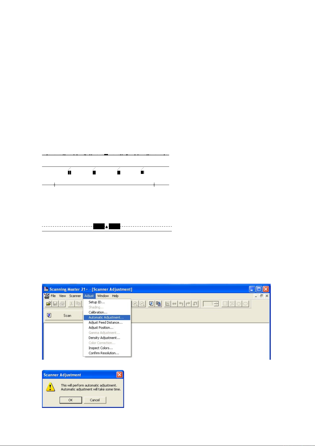
9. ADJUSTMENTS USING THE SOFTWARE
641711400 071025
A0
A1
24
A1
A2
18
A2
A3
12
A3
A4
9
A4
A4
9
A3
A4
12
A2
A3
18A1
A2
24
A0
A1
A2
A3
12
A3
A4
9
A4
9.4.3 Sensor Stitch Adjustment
In the following cases, perform this adjustment.
• When the sensor jointing is misaligned.
• When you replaced the main board.
• When you replaced or removed the CIS sensors.
Adjusting the sensor stitch
There are two ways to adjust the sensor stitch, which are the auto-sensor stitch adjustment and the manual
sensor stitch adjustment.
Perform the auto-stitch adjustment normally.
Perform the manual sensor stitch adjustment if you do not have the auto-sensor stitch chart or the auto-
sensor stitch adjustment is not performed correctly by using the bad condition of auto-sensor stitch
adjustment chart.
Adjusting the sensor stitch by auto sensor stitch adjustment
(1) Prepare the auto-sensor stitch adjustment chart.
(2) Run the software. (See page 9-1) This is not necessary when the software is running already.
(3) Insert the auto-sensor stitch adjustment chart into the scanner.
Position the center arrow mark of the auto sensor stitch adjustment chart to the center of the scanner
and insert the auto sensor stitch adjustment chart.
(4) Select "Auto Adjustment" from the "Adjust" menu.
(5) The following dialog box will appear. Click the "OK" button to start the sensor stitch adjustment.
The scanner start the stitch adjustment immediately.
CSX300-UM-251-9370 9-13
Page 88

9. ADJUSTMENTS USING THE SOFTWARE
(6) The following dialog box will appear when the sensor stitch adjustment has been completed.
(7) Click the "Close" button to exit the sensor stitch adjustment.
(8) Perform the scanning start position adjustment, because the auto sensor stitch adjustment reset the
scanning start position to be 0.
CSX300-UM-251-9370 9-14
Page 89
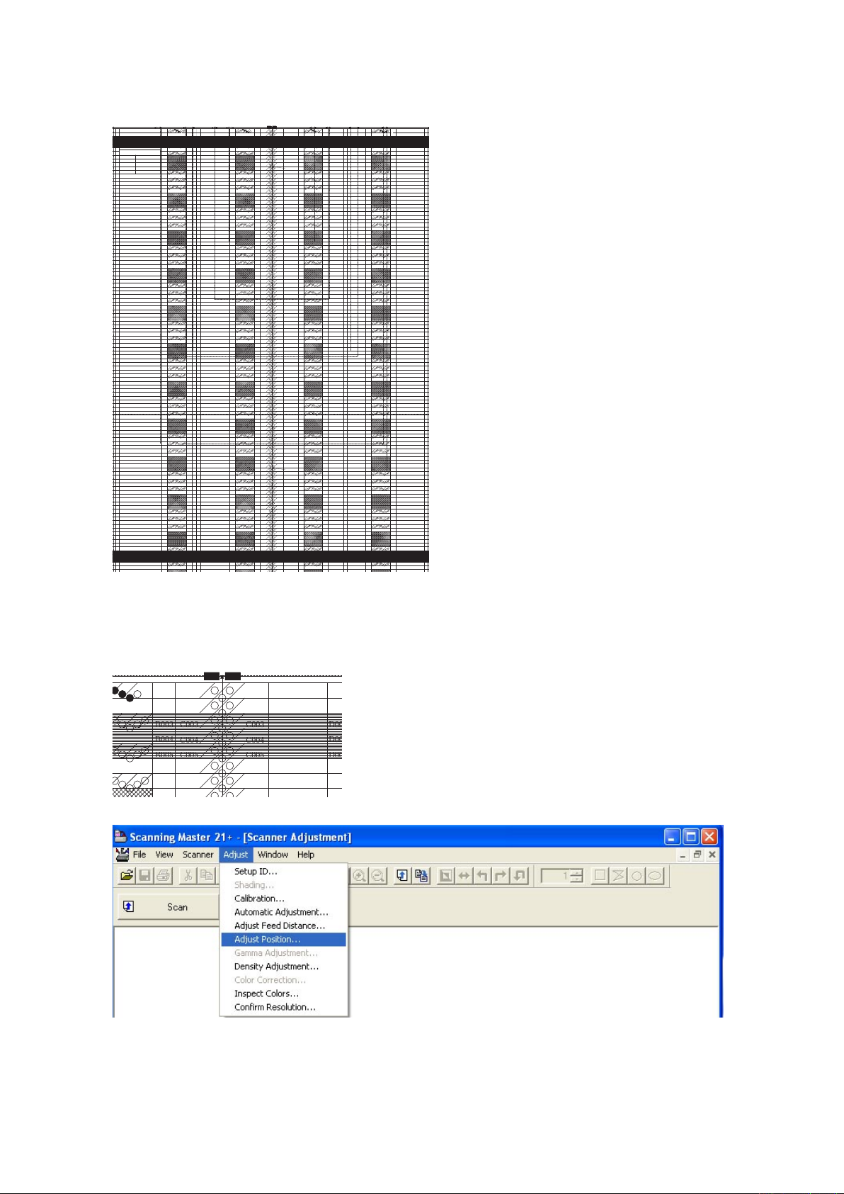
9. ADJUSTMENTS USING THE SOFTWARE
CSX300 Adjustment Chart
Distances between two points Note measured distances below
C010-C090
A001
A002
A003
A004
A005
A006
A007
A008
A009
A010
A011
A008
A009
A010
A011
A008
A009
A010
A011
A008
A009
A010
A011
A012
A013
A014
A015
A016
A017
A018
A019
A020
A021
A018
A019
A020
A021
A018
A019
A020
A021
A018
A019
A020
A021
A022
A023
A024
A025
A026
A027
A028
A029
A030
A031
A028
A029
A030
A031
A028
A029
A030
A031
A028
A029
A030
A031
A032
A034
A035
A036
A037
A038
A039
A040
A041
A038
A039
A040
A041
A038
A039
A040
A041
A038
A039
A040
A041
A042
A043
A044
A045
A046
A047
A048
A049
A050
A051
A048
A049
A050
A051
A048
A049
A050
A051
A048
A049
A050
A051
A052
A053
A054
A055
A056
A057
A058
A059
A060
A061
A058
A059
A060
A061
A058
A059
A060
A061
A058
A059
A060
A061
A062
A063
A064
A065
A066
A067
A068
A069
A070
A071
A068
A069
A070
A071
A068
A069
A070
A071
A068
A069
A070
A071
A072
A073
A074
A075
A076
A077
A078
A079
A080
A081
A078
A079
A080
A081
A078
A079
A080
A081
A078
A079
A080
A081
A082
A083
A084
A085
A086
A088
A087
A089
A090
A091
A088
A089
A090
A091
A088
A089
A090
A091
A088
A089
A090
A091
A092
A093
A094
A095
A096
A097
A098
A099
A100
A101
A098
A099
A100
A101
A098
A099
A100
A101
A098
A099
A100
A101
A102
A103
A104
A105
A106
A107
A108
A109
A110
A111
A108
A109
A110
A111
A108
A109
A110
A111
A108
A109
A110
A111
A112
A113
A114
A115
A116
A117
A033
A001
A002
A003
A004
A005
A006
A007
A008
A009
A010
A011
A012
A013
A014
A015
A016
A017
A018
A019
A020
A021
A022
A023
A024
A025
A026
A027
A028
A029
A030
A031
A032
A034
A035
A036
A037
A038
A039
A040
A041
A042
A043
A044
A045
A046
A047
A048
A049
A050
A051
A052
A053
A054
A055
A056
A057
A058
A059
A060
A061
A062
A063
A064
A065
A066
A067
A068
A069
A070
A071
A072
A073
A074
A075
A076
A077
A078
A079
A080
A081
A082
A083
A084
A085
A086
A088
A087
A089
A090
A091
A092
A093
A094
A095
A096
A097
A098
A099
A100
A101
A102
A103
A104
A105
A106
A107
A108
A109
A110
A111
A112
A113
A114
A115
A116
A117
A033
B001
B002
B003
B004
B005
B006
B007
B008
B009
B010
B011
B008
B009
B010
B011
B008
B009
B010
B011
B008
B009
B010
B011
B012
B013
B014
B015
B016
B017
B018
B019
B020
B021
B018
B019
B020
B021
B018
B019
B020
B021
B018
B019
B020
B021
B022
B023
B024
B025
B026
B027
B028
B029
B030
B031
B028
B029
B030
B031
B028
B029
B030
B031
B028
B029
B030
B031
B032
B034
B035
B036
B037
B038
B039
B040
B041
B038
B039
B040
B041
B038
B039
B040
B041
B038
B039
B040
B041
B042
B043
B044
B045
B046
B047
B048
B049
B050
B051
B048
B049
B050
B051
B048
B049
B050
B051
B048
B049
B050
B051
B052
B053
B054
B055
B056
B057
B058
B059
B060
B061
B058
B059
B060
B061
B058
B059
B060
B061
B058
B059
B060
B061
B062
B063
B064
B065
B066
B067
B068
B069
B070
B071
B068
B069
B070
B071
B068
B069
B070
B071
B068
B069
B070
B071
B072
B073
B074
B075
B076
B077
B078
B079
B080
B081
B078
B079
B080
B081
B078
B079
B080
B081
B078
B079
B080
B081
B082
B083
B084
B085
B086
B088
B087
B089
B090
B091
B088
B089
B090
B091
B088
B089
B090
B091
B088
B089
B090
B091
B092
B093
B094
B095
B096
B097
B098
B099
B100
B101
B098
B099
B100
B101
B098
B099
B100
B101
B098
B099
B100
B101
B102
B103
B104
B105
B106
B107
B108
B109
B110
B111
B108
B109
B110
B111
B108
B109
B110
B111
B108
B109
B110
B111
B112
B113
B114
B115
B116
B117
B033
B001
B002
B003
B004
B005
B006
B007
B008
B009
B010
B011
B012
B013
B014
B015
B016
B017
B018
B019
B020
B021
B022
B023
B024
B025
B026
B027
B028
B029
B030
B031
B032
B034
B035
B036
B037
B038
B039
B040
B041
B042
B043
B044
B045
B046
B047
B048
B049
B050
B051
B052
B053
B054
B055
B056
B057
B058
B059
B060
B061
B062
B063
B064
B065
B066
B067
B068
B069
B070
B071
B072
B073
B074
B075
B076
B077
B078
B079
B080
B081
B082
B083
B084
B085
B086
B088
B087
B089
B090
B091
B092
B093
B094
B095
B096
B097
B098
B099
B100
B101
B102
B103
B104
B105
B106
B107
B108
B109
B110
B111
B112
B113
B114
B115
B116
B117
B033
D001
D002
D003
D004
D005
D006
D007
D008
D009
D010
D011
D008
D009
D010
D011
D008
D009
D010
D011
D008
D009
D010
D011
D012
D013
D014
D015
D016
D017
D018
D019
D020
D021
D018
D019
D020
D021
D018
D019
D020
D021
D018
D019
D020
D021
D022
D023
D024
D025
D026
D027
D028
D029
D030
D031
D028
D029
D030
D031
D028
D029
D030
D031
D028
D029
D030
D031
D032
D034
D035
D036
D037
D038
D039
D040
D041
D038
D039
D040
D041
D038
D039
D040
D041
D038
D039
D040
D041
D042
D043
D044
D045
D046
D047
D048
D049
D050
D051
D048
D049
D050
D051
D048
D049
D050
D051
D048
D049
D050
D051
D052
D053
D054
D055
D056
D057
D058
D059
D060
D061
D058
D059
D060
D061
D058
D059
D060
D061
D058
D059
D060
D061
D062
D063
D064
D065
D066
D067
D068
D069
D070
D071
D068
D069
D070
D071
D068
D069
D070
D071
D068
D069
D070
D071
D072
D073
D074
D075
D076
D077
D078
D079
D080
D081
D078
D079
D080
D081
D078
D079
D080
D081
D078
D079
D080
D081
D082
D083
D084
D085
D086
D088
D087
D089
D090
D091
D088
D089
D090
D091
D088
D089
D090
D091
D088
D089
D090
D091
D092
D093
D094
D095
D096
D097
D098
D099
D100
D101
D098
D099
D100
D101
D098
D099
D100
D101
D098
D099
D100
D101
D102
D103
D104
D105
D106
D107
D108
D109
D110
D111
D108
D109
D110
D111
D108
D109
D110
D111
D108
D109
D110
D111
D112
D113
D114
D115
D116
D117
D033
D001
D002
D003
D004
D005
D006
D007
D008
D009
D010
D011
D012
D013
D014
D015
D016
D017
D018
D019
D020
D021
D022
D023
D024
D025
D026
D027
D028
D029
D030
D031
D032
D034
D035
D036
D037
D038
D039
D040
D041
D042
D043
D044
D045
D046
D047
D048
D049
D050
D051
D052
D053
D054
D055
D056
D057
D058
D059
D060
D061
D062
D063
D064
D065
D066
D067
D068
D069
D070
D071
D072
D073
D074
D075
D076
D077
D078
D079
D080
D081
D082
D083
D084
D085
D086
D088
D087
D089
D090
D091
D092
D093
D094
D095
D096
D097
D098
D099
D100
D101
D102
D103
D104
D105
D106
D107
D108
D109
D110
D111
D112
D113
D114
D115
D116
D117
D033
E001
E002
E003
E004
E005
E006
E007
E008
E009
E010
E011
E008
E009
E010
E011
E008
E009
E010
E011
E008
E009
E010
E011
E012
E013
E014
E015
E016
E017
E018
E019
E020
E021
E018
E019
E020
E021
E018
E019
E020
E021
E018
E019
E020
E021
E022
E023
E024
E025
E026
E027
E028
E029
E030
E031
E028
E029
E030
E031
E028
E029
E030
E031
E028
E029
E030
E031
E032
E034
E035
E036
E037
E038
E039
E040
E041
E038
E039
E040
E041
E038
E039
E040
E041
E038
E039
E040
E041
E042
E043
E044
E045
E046
E047
E048
E049
E050
E051
E048
E049
E050
E051
E048
E049
E050
E051
E048
E049
E050
E051
E052
E053
E054
E055
E056
E057
E058
E059
E060
E061
E058
E059
E060
E061
E058
E059
E060
E061
E058
E059
E060
E061
E062
E063
E064
E065
E066
E067
E068
E069
E070
E071
E068
E069
E070
E071
E068
E069
E070
E071
E068
E069
E070
E071
E072
E073
E074
E075
E076
E077
E078
E079
E080
E081
E078
E079
E080
E081
E078
E079
E080
E081
E078
E079
E080
E081
E082
E083
E084
E085
E086
E088
E087
E089
E090
E091
E088
E089
E090
E091
E088
E089
E090
E091
E088
E089
E090
E091
E092
E093
E094
E095
E096
E097
E098
E099
E100
E101
E098
E099
E100
E101
E098
E099
E100
E101
E098
E099
E100
E101
E102
E103
E104
E105
E106
E107
E108
E109
E110
E111
E108
E109
E110
E111
E108
E109
E110
E111
E108
E109
E110
E111
E112
E113
E114
E115
E116
E117
E033
E001
E002
E003
E004
E005
E006
E007
E008
E009
E010
E011
E012
E013
E014
E015
E016
E017
E018
E019
E020
E021
E022
E023
E024
E025
E026
E027
E028
E029
E030
E031
E032
E034
E035
E036
E037
E038
E039
E040
E041
E042
E043
E044
E045
E046
E047
E048
E049
E050
E051
E052
E053
E054
E055
E056
E057
E058
E059
E060
E061
E062
E063
E064
E065
E066
E067
E068
E069
E070
E071
E072
E073
E074
E075
E076
E077
E078
E079
E080
E081
E082
E083
E084
E085
E086
E088
E087
E089
E090
E091
E092
E093
E094
E095
E096
E097
E098
E099
E100
E101
E102
E103
E104
E105
E106
E107
E108
E109
E110
E111
E112
E113
E114
E115
E116
E117
E033
C001
C002
C003
C004
C005
C006
C007
C008
C009
C010
C011
C012
C013
C014
C015
C016
C017
C018
C019
C020
C021
C022
C023
C024
C025
C026
C027
C028
C029
C030
C031
C032
C034
C035
C036
C037
C038
C039
C040
C041
C042
C043
C044
C045
C046
C047
C048
C049
C050
C051
C052
C053
C054
C055
C056
C057
C058
C059
C060
C061
C062
C063
C064
C065
C066
C067
C068
C069
C070
C071
C072
C073
C074
C075
C076
C077
C078
C079
C080
C081
C082
C083
C084
C085
C086
C088
C087
C089
C090
C091
C092
C093
C094
C095
C096
C097
C098
C099
C100
C101
C102
C103
C104
C105
C106
C107
C108
C109
C110
C111
C112
C113
C114
C115
C116
C117
C033
A0
A1
24
A1
A2
18
A2
A3
12
A3
A4
9
A4
A4
9
A4
A3
12
A3
A2
18
A1
A2
24
C010
C090
7
8
9
6
5
4
3
2
1
7
8
9
6
5
4
3
2
1
7
8
9
6
5
4
3
2
1
7
8
9
6
5
4
3
2
1
7
8
9
6
5
4
3
2
1
7
8
9
6
5
4
3
2
1
7
8
9
6
5
4
3
2
1
7
8
9
6
5
4
3
2
1
7
8
9
6
5
4
3
2
1
7
8
9
6
5
4
3
2
1
7
8
9
6
5
4
3
2
1
7
8
9
6
5
4
3
2
1
7
8
9
6
5
4
3
2
1
7
8
9
6
5
4
3
2
1
7
8
9
6
5
4
3
2
1
7
8
9
6
5
4
3
2
1
7
8
9
6
5
4
3
2
1
7
8
9
6
5
4
3
2
1
7
8
9
6
5
4
3
2
1
7
8
9
6
5
4
3
2
1
7
8
9
6
5
4
3
2
1
7
8
9
6
5
4
3
2
1
7
8
9
6
5
4
3
2
1
7
8
9
6
5
4
3
2
1
7
8
9
6
5
4
3
2
1
7
8
9
6
5
4
3
2
1
7
8
9
6
5
4
3
2
1
7
8
9
6
5
4
3
2
1
7
8
9
6
5
4
3
2
1
7
8
9
6
5
4
3
2
1
7
8
9
6
5
4
3
2
1
7
8
9
6
5
4
3
2
1
7
8
9
6
5
4
3
2
1
7
8
9
6
5
4
3
2
1
7
8
9
6
5
4
3
2
1
7
8
9
6
5
4
3
2
1
7
8
9
6
5
4
3
2
1
7
8
9
6
5
4
3
2
1
7
8
9
6
5
4
3
2
1
7
8
9
6
5
4
3
2
1
7
8
9
6
5
4
3
2
1
7
8
9
6
5
4
3
2
1
7
8
9
6
5
4
3
2
1
7
8
9
6
5
4
3
2
1
7
8
9
6
5
4
3
2
1
7
8
9
6
5
4
3
2
1
7
8
9
6
5
4
3
2
1
7
8
9
6
5
4
3
2
1
7
8
9
6
5
4
3
2
1
7
8
9
6
5
4
3
2
1
7
8
9
6
5
4
3
2
1
7
8
9
6
5
4
3
2
1
7
8
9
6
5
4
3
2
1
7
8
9
6
5
4
3
2
1
7
8
9
6
5
4
3
2
1
7
8
9
6
5
4
3
2
1
7
8
9
6
5
4
3
2
1
7
8
9
6
5
4
3
2
1
7
8
9
6
5
4
3
2
1
7
8
9
6
5
4
3
2
1
7
8
9
6
5
4
3
2
1
7
8
9
6
5
4
3
2
1
7
8
9
6
5
4
3
2
1
7
8
9
6
5
4
3
2
1
7
8
9
6
5
4
3
2
1
7
8
9
6
5
4
3
2
1
7
8
9
6
5
4
3
2
1
7
8
9
6
5
4
3
2
1
7
8
9
6
5
4
3
2
1
7
8
9
6
5
4
3
2
1
7
8
9
6
5
4
3
2
1
7
8
9
6
5
4
3
2
1
7
8
9
6
5
4
3
2
2
1
7
8
6
5
4
3
7
8
9
6
5
4
3
2
1
7
8
9
6
5
4
3
2
1
7
8
9
6
5
4
3
2
1
7
8
9
6
5
4
3
2
1
7
8
9
6
5
4
3
2
1
7
8
9
6
5
4
3
2
1
7
8
9
6
5
4
3
2
1
7
8
9
6
5
4
3
2
1
7
8
9
6
5
4
3
2
1
7
8
9
6
5
4
3
2
1
7
8
9
6
5
4
3
2
1
7
8
9
6
5
4
3
2
1
7
8
9
6
5
4
3
2
1
7
8
9
6
5
4
3
2
1
7
8
9
6
5
4
3
2
1
7
8
9
6
5
4
3
2
1
7
8
9
6
5
4
3
2
1
7
8
9
6
5
4
3
2
1
7
8
9
6
5
4
3
2
1
7
8
9
6
5
4
3
2
1
7
8
9
6
5
4
3
2
1
7
8
9
6
5
4
3
2
1
7
8
9
6
5
4
3
2
1
7
8
9
6
5
4
3
2
1
7
8
9
6
5
4
3
2
1
7
8
9
6
5
4
3
2
1
7
8
9
6
5
4
3
2
1
7
8
9
6
5
4
3
2
1
7
8
9
6
5
4
3
2
1
7
8
9
6
5
4
3
2
1
7
8
9
6
5
4
3
2
1
7
8
9
6
5
4
3
2
1
7
8
9
6
5
4
3
2
1
7
8
9
6
5
4
3
2
1
7
8
9
6
5
3
2
1
7
8
9
6
5
4
4
3
2
1
1 1
7
8
6
5
4
3
2
7
8
9
6
5
4
3
2
1
7
8
9
6
5
4
3
2
1
7
8
9
6
5
4
3
2
1
7
8
9
6
5
4
3
2
1
7
8
9
6
5
4
3
2
1
7
8
9
6
5
4
3
2
1
7
8
9
6
5
4
3
2
1
7
8
9
6
5
4
3
2
1
7
8
9
6
5
4
3
2
1
7
8
9
6
5
4
3
2
1
7
8
9
6
5
4
3
2
1
7
8
9
6
5
4
3
2
1
7
8
9
6
5
4
3
2
1
7
8
9
6
5
4
3
2
1
7
8
9
6
5
4
3
2
1
7
8
9
6
5
4
3
2
1
7
8
9
6
5
4
3
2
1
7
8
9
6
5
4
3
2
1
7
8
9
6
5
4
3
2
1
7
8
9
6
5
4
3
2
1
7
8
9
6
5
4
3
2
1
7
8
9
6
5
4
3
2
1
7
8
9
6
5
4
3
2
1
7
8
9
6
5
4
3
2
1
7
8
9
6
5
4
3
2
1
7
8
9
6
5
4
3
2
1
7
8
9
6
5
4
3
2
1
7
8
9
6
5
4
3
2
1
7
8
9
6
5
4
3
2
1
7
8
9
6
5
4
3
2
1
7
8
9
6
5
4
3
2
1
7
8
9
6
5
4
3
2
1
7
8
9
6
5
4
3
2
1
7
8
9
6
5
4
3
2
1
7
8
9
6
5
4
3
2
1
7
8
9
6
5
4
3
2
1
7
8
9
6
5
4
3
2
1
Cut along this dotted line Cut along this dotted line Cut along this dotted lineCut along this dotted line
B001
B002
B003
B004
B005
B006
B007
D001
D002
D003
D004
D005
D006
D007
D001
D002
D003
D004
D005
D006
D007
E001
E002
E003
E004
E005
E006
E007
E001
E002
E003
E004
E005
E006
E007
C001
C002
C003
C004
C005
C006
C007
C001
C002
C003
C004
C005
C006
C007
A0
A1
24
A1
A2
18
A2
A3
12
A3
A4
9
A4
7
8
9
6
5
4
3
2
1
7
8
9
6
5
4
3
2
1
7
8
9
6
5
4
3
2
1
7
8
9
6
5
4
3
2
1
7
8
9
6
5
4
3
2
1
7
8
9
6
5
4
3
2
1
7
8
9
6
5
4
3
2
2
1
7
8
6
5
4
3
7
8
9
6
5
7
8
9
6
5
7
8
9
6
5
7
8
6
5
Adjusting the sensor stitch by manual sensor stitch adjustment
(1) Prepare the CSX300 adjustment test chart.
(2) Run the software. (See page 9-1) This is not necessary when the software is running already.
(3) Insert the CSX300 adjustment test chart into the scanner.
Position the center arrow mark of the CSX300 adjustment test chart to the center of the scanner and
insert the CSX300 adjustment test chart.
(4) Select "Adjust Position" from the "Adjust" menu.
CSX300-UM-251-9370 9-15
Page 90

9. ADJUSTMENTS USING THE SOFTWARE
(5) The following dialog box will appear. Confirm that the CSX300 test chart is inserted to the scanner
correctly, and then click the "Scan" button.
(6) The following dialog box will appear. Click the "Scan" button.
CSX300-UM-251-9370 9-16
Page 91
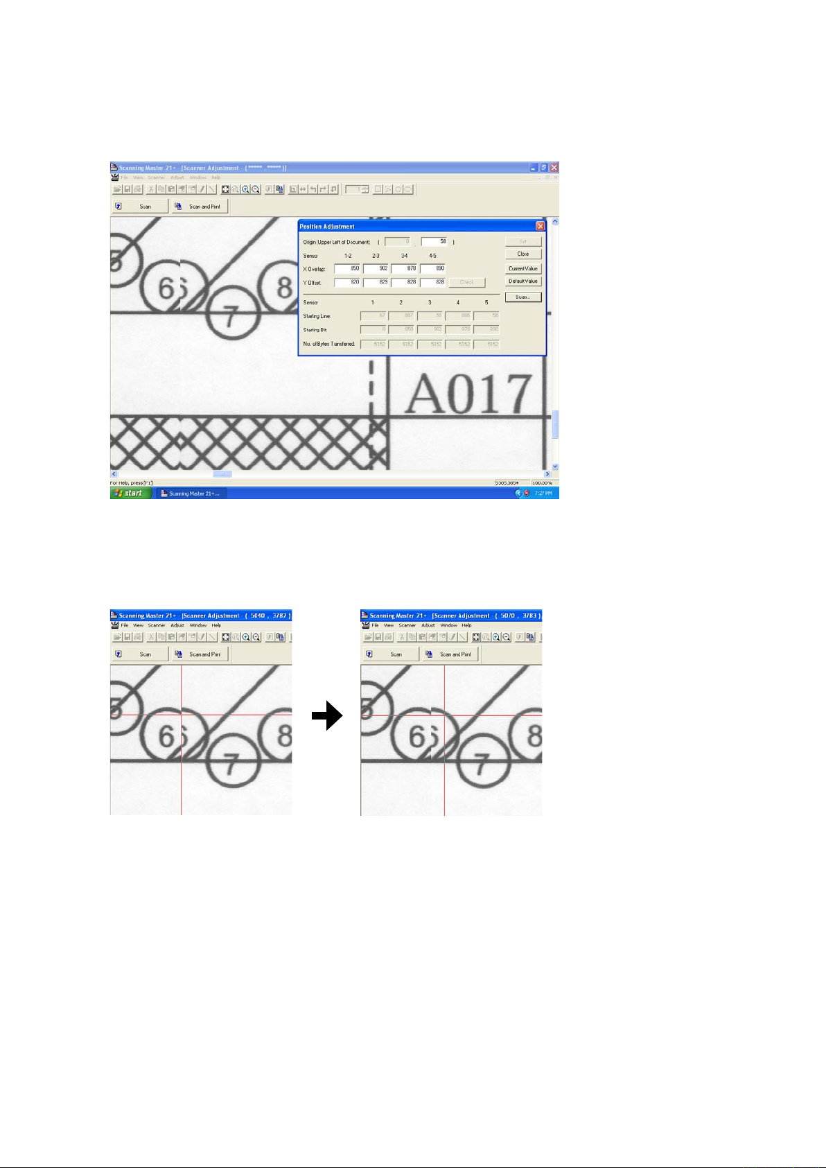
9. ADJUSTMENTS USING THE SOFTWARE
(7) The image appears as shown below.
Then confirm the jointing area of sensors from the A area to E area.
At this time, confirm around 017 lines, because the top part of target is not stable to contact the CIS
sensors.
(8) The image appears as shown above with the left-hand portion of the image misaligned with the right-
hand portion.
Click anywhere in the X Overlap box under "1-2" (A area).
(9) The crosshairs cursor will appear. First click a position on the left-hand portion, then click the position of
the right-hand portion that corresponds to the position you selected first.
(10) Click the "Check" button first, then click the "Set" button. Follow the on-screen instruction to place the
adjustment chart on the scanner again.
(11) Repeat these steps until the left-hand portion is properly aligned with the right-hand portion.
In this task, you need to adjust the X overlap and Y offset at the same time.
See "Tips for Making Fine Adjustments" on the next page if you encounter difficulties making fine
adjustments.
(12) Similarly, make adjustments for 2-3 (B area), 3-4 (D area), and 4-5 (E area) in this order if there is
misaligned.
After finishing, close all the adjustment menu windows. Use the CSX300 test chart to perform a normal
scan, and confirm that the image appears properly.
CSX300-UM-251-9370 9-17
Page 92

Image after adjustments
Use the cursor or keys to enter a value to
adjust level differences between the image sensors.
Use the cursor or keys to enter
the position of the origin.
Not used.
0
0 0 1600
1600
1200 1200 1200 1200
9. ADJUSTMENTS USING THE SOFTWARE
Tips for Making Fine Adjustments
• Two portions of the aligned image become misaligned during adjustments using the crosshairs cursor.
• You wish to move a portion of the image by one pixel.
• You find it difficult to find whether any portions of the image are misaligned.
• You feel that some portions of the image remain misaligned, despite efforts to correct the alignment.
In these cases, simply type in numbers to make adjustments.
In this section, we will give you a rough idea of what the numbers in the dialog box mean.
Once you become familiar with the meanings of these numbers and know which numbers to type in, you can
make adjustments more accurately and quickly than by using the crosshairs cursor.
CSX300-UM-251-9370 9-18
Page 93

9. ADJUSTMENTS USING THE SOFTWARE
CSX300 Adjustment Chart
Distances between two points Note measured distances below
C010-C090
A001
A002
A003
A004
A005
A006
A007
A008
A009
A010
A011
A008
A009
A010
A011
A008
A009
A010
A011
A008
A009
A010
A011
A012
A013
A014
A015
A016
A017
A018
A019
A020
A021
A018
A019
A020
A021
A018
A019
A020
A021
A018
A019
A020
A021
A022
A023
A024
A025
A026
A027
A028
A029
A030
A031
A028
A029
A030
A031
A028
A029
A030
A031
A028
A029
A030
A031
A032
A034
A035
A036
A037
A038
A039
A040
A041
A038
A039
A040
A041
A038
A039
A040
A041
A038
A039
A040
A041
A042
A043
A044
A045
A046
A047
A048
A049
A050
A051
A048
A049
A050
A051
A048
A049
A050
A051
A048
A049
A050
A051
A052
A053
A054
A055
A056
A057
A058
A059
A060
A061
A058
A059
A060
A061
A058
A059
A060
A061
A058
A059
A060
A061
A062
A063
A064
A065
A066
A067
A068
A069
A070
A071
A068
A069
A070
A071
A068
A069
A070
A071
A068
A069
A070
A071
A072
A073
A074
A075
A076
A077
A078
A079
A080
A081
A078
A079
A080
A081
A078
A079
A080
A081
A078
A079
A080
A081
A082
A083
A084
A085
A086
A088
A087
A089
A090
A091
A088
A089
A090
A091
A088
A089
A090
A091
A088
A089
A090
A091
A092
A093
A094
A095
A096
A097
A098
A099
A100
A101
A098
A099
A100
A101
A098
A099
A100
A101
A098
A099
A100
A101
A102
A103
A104
A105
A106
A107
A108
A109
A110
A111
A108
A109
A110
A111
A108
A109
A110
A111
A108
A109
A110
A111
A112
A113
A114
A115
A116
A117
A033
A001
A002
A003
A004
A005
A006
A007
A008
A009
A010
A011
A012
A013
A014
A015
A016
A017
A018
A019
A020
A021
A022
A023
A024
A025
A026
A027
A028
A029
A030
A031
A032
A034
A035
A036
A037
A038
A039
A040
A041
A042
A043
A044
A045
A046
A047
A048
A049
A050
A051
A052
A053
A054
A055
A056
A057
A058
A059
A060
A061
A062
A063
A064
A065
A066
A067
A068
A069
A070
A071
A072
A073
A074
A075
A076
A077
A078
A079
A080
A081
A082
A083
A084
A085
A086
A088
A087
A089
A090
A091
A092
A093
A094
A095
A096
A097
A098
A099
A100
A101
A102
A103
A104
A105
A106
A107
A108
A109
A110
A111
A112
A113
A114
A115
A116
A117
A033
B001
B002
B003
B004
B005
B006
B007
B008
B009
B010
B011
B008
B009
B010
B011
B008
B009
B010
B011
B008
B009
B010
B011
B012
B013
B014
B015
B016
B017
B018
B019
B020
B021
B018
B019
B020
B021
B018
B019
B020
B021
B018
B019
B020
B021
B022
B023
B024
B025
B026
B027
B028
B029
B030
B031
B028
B029
B030
B031
B028
B029
B030
B031
B028
B029
B030
B031
B032
B034
B035
B036
B037
B038
B039
B040
B041
B038
B039
B040
B041
B038
B039
B040
B041
B038
B039
B040
B041
B042
B043
B044
B045
B046
B047
B048
B049
B050
B051
B048
B049
B050
B051
B048
B049
B050
B051
B048
B049
B050
B051
B052
B053
B054
B055
B056
B057
B058
B059
B060
B061
B058
B059
B060
B061
B058
B059
B060
B061
B058
B059
B060
B061
B062
B063
B064
B065
B066
B067
B068
B069
B070
B071
B068
B069
B070
B071
B068
B069
B070
B071
B068
B069
B070
B071
B072
B073
B074
B075
B076
B077
B078
B079
B080
B081
B078
B079
B080
B081
B078
B079
B080
B081
B078
B079
B080
B081
B082
B083
B084
B085
B086
B088
B087
B089
B090
B091
B088
B089
B090
B091
B088
B089
B090
B091
B088
B089
B090
B091
B092
B093
B094
B095
B096
B097
B098
B099
B100
B101
B098
B099
B100
B101
B098
B099
B100
B101
B098
B099
B100
B101
B102
B103
B104
B105
B106
B107
B108
B109
B110
B111
B108
B109
B110
B111
B108
B109
B110
B111
B108
B109
B110
B111
B112
B113
B114
B115
B116
B117
B033
B001
B002
B003
B004
B005
B006
B007
B008
B009
B010
B011
B012
B013
B014
B015
B016
B017
B018
B019
B020
B021
B022
B023
B024
B025
B026
B027
B028
B029
B030
B031
B032
B034
B035
B036
B037
B038
B039
B040
B041
B042
B043
B044
B045
B046
B047
B048
B049
B050
B051
B052
B053
B054
B055
B056
B057
B058
B059
B060
B061
B062
B063
B064
B065
B066
B067
B068
B069
B070
B071
B072
B073
B074
B075
B076
B077
B078
B079
B080
B081
B082
B083
B084
B085
B086
B088
B087
B089
B090
B091
B092
B093
B094
B095
B096
B097
B098
B099
B100
B101
B102
B103
B104
B105
B106
B107
B108
B109
B110
B111
B112
B113
B114
B115
B116
B117
B033
D001
D002
D003
D004
D005
D006
D007
D008
D009
D010
D011
D008
D009
D010
D011
D008
D009
D010
D011
D008
D009
D010
D011
D012
D013
D014
D015
D016
D017
D018
D019
D020
D021
D018
D019
D020
D021
D018
D019
D020
D021
D018
D019
D020
D021
D022
D023
D024
D025
D026
D027
D028
D029
D030
D031
D028
D029
D030
D031
D028
D029
D030
D031
D028
D029
D030
D031
D032
D034
D035
D036
D037
D038
D039
D040
D041
D038
D039
D040
D041
D038
D039
D040
D041
D038
D039
D040
D041
D042
D043
D044
D045
D046
D047
D048
D049
D050
D051
D048
D049
D050
D051
D048
D049
D050
D051
D048
D049
D050
D051
D052
D053
D054
D055
D056
D057
D058
D059
D060
D061
D058
D059
D060
D061
D058
D059
D060
D061
D058
D059
D060
D061
D062
D063
D064
D065
D066
D067
D068
D069
D070
D071
D068
D069
D070
D071
D068
D069
D070
D071
D068
D069
D070
D071
D072
D073
D074
D075
D076
D077
D078
D079
D080
D081
D078
D079
D080
D081
D078
D079
D080
D081
D078
D079
D080
D081
D082
D083
D084
D085
D086
D088
D087
D089
D090
D091
D088
D089
D090
D091
D088
D089
D090
D091
D088
D089
D090
D091
D092
D093
D094
D095
D096
D097
D098
D099
D100
D101
D098
D099
D100
D101
D098
D099
D100
D101
D098
D099
D100
D101
D102
D103
D104
D105
D106
D107
D108
D109
D110
D111
D108
D109
D110
D111
D108
D109
D110
D111
D108
D109
D110
D111
D112
D113
D114
D115
D116
D117
D033
D001
D002
D003
D004
D005
D006
D007
D008
D009
D010
D011
D012
D013
D014
D015
D016
D017
D018
D019
D020
D021
D022
D023
D024
D025
D026
D027
D028
D029
D030
D031
D032
D034
D035
D036
D037
D038
D039
D040
D041
D042
D043
D044
D045
D046
D047
D048
D049
D050
D051
D052
D053
D054
D055
D056
D057
D058
D059
D060
D061
D062
D063
D064
D065
D066
D067
D068
D069
D070
D071
D072
D073
D074
D075
D076
D077
D078
D079
D080
D081
D082
D083
D084
D085
D086
D088
D087
D089
D090
D091
D092
D093
D094
D095
D096
D097
D098
D099
D100
D101
D102
D103
D104
D105
D106
D107
D108
D109
D110
D111
D112
D113
D114
D115
D116
D117
D033
E001
E002
E003
E004
E005
E006
E007
E008
E009
E010
E011
E008
E009
E010
E011
E008
E009
E010
E011
E008
E009
E010
E011
E012
E013
E014
E015
E016
E017
E018
E019
E020
E021
E018
E019
E020
E021
E018
E019
E020
E021
E018
E019
E020
E021
E022
E023
E024
E025
E026
E027
E028
E029
E030
E031
E028
E029
E030
E031
E028
E029
E030
E031
E028
E029
E030
E031
E032
E034
E035
E036
E037
E038
E039
E040
E041
E038
E039
E040
E041
E038
E039
E040
E041
E038
E039
E040
E041
E042
E043
E044
E045
E046
E047
E048
E049
E050
E051
E048
E049
E050
E051
E048
E049
E050
E051
E048
E049
E050
E051
E052
E053
E054
E055
E056
E057
E058
E059
E060
E061
E058
E059
E060
E061
E058
E059
E060
E061
E058
E059
E060
E061
E062
E063
E064
E065
E066
E067
E068
E069
E070
E071
E068
E069
E070
E071
E068
E069
E070
E071
E068
E069
E070
E071
E072
E073
E074
E075
E076
E077
E078
E079
E080
E081
E078
E079
E080
E081
E078
E079
E080
E081
E078
E079
E080
E081
E082
E083
E084
E085
E086
E088
E087
E089
E090
E091
E088
E089
E090
E091
E088
E089
E090
E091
E088
E089
E090
E091
E092
E093
E094
E095
E096
E097
E098
E099
E100
E101
E098
E099
E100
E101
E098
E099
E100
E101
E098
E099
E100
E101
E102
E103
E104
E105
E106
E107
E108
E109
E110
E111
E108
E109
E110
E111
E108
E109
E110
E111
E108
E109
E110
E111
E112
E113
E114
E115
E116
E117
E033
E001
E002
E003
E004
E005
E006
E007
E008
E009
E010
E011
E012
E013
E014
E015
E016
E017
E018
E019
E020
E021
E022
E023
E024
E025
E026
E027
E028
E029
E030
E031
E032
E034
E035
E036
E037
E038
E039
E040
E041
E042
E043
E044
E045
E046
E047
E048
E049
E050
E051
E052
E053
E054
E055
E056
E057
E058
E059
E060
E061
E062
E063
E064
E065
E066
E067
E068
E069
E070
E071
E072
E073
E074
E075
E076
E077
E078
E079
E080
E081
E082
E083
E084
E085
E086
E088
E087
E089
E090
E091
E092
E093
E094
E095
E096
E097
E098
E099
E100
E101
E102
E103
E104
E105
E106
E107
E108
E109
E110
E111
E112
E113
E114
E115
E116
E117
E033
C001
C002
C003
C004
C005
C006
C007
C008
C009
C010
C011
C012
C013
C014
C015
C016
C017
C018
C019
C020
C021
C022
C023
C024
C025
C026
C027
C028
C029
C030
C031
C032
C034
C035
C036
C037
C038
C039
C040
C041
C042
C043
C044
C045
C046
C047
C048
C049
C050
C051
C052
C053
C054
C055
C056
C057
C058
C059
C060
C061
C062
C063
C064
C065
C066
C067
C068
C069
C070
C071
C072
C073
C074
C075
C076
C077
C078
C079
C080
C081
C082
C083
C084
C085
C086
C088
C087
C089
C090
C091
C092
C093
C094
C095
C096
C097
C098
C099
C100
C101
C102
C103
C104
C105
C106
C107
C108
C109
C110
C111
C112
C113
C114
C115
C116
C117
C033
C001
C002
C003
C004
C005
C006
C007
C008
C009
C010
C011
C012
C013
C014
C015
C016
C017
C018
C019
C020
C021
C022
C023
C024
C025
C026
C027
C028
C029
C030
C031
C032
C034
C035
C036
C037
C038
C039
C040
C041
C042
C043
C044
C045
C046
C047
C048
C049
C050
C051
C052
C053
C054
C055
C056
C057
C058
C059
C060
C061
C062
C063
C064
C065
C066
C067
C068
C069
C070
C071
C072
C073
C074
C075
C076
C077
C078
C079
C080
C081
C082
C083
C084
C085
C086
C088
C087
C089
C090
C091
C092
C093
C094
C095
C096
C097
C098
C099
C100
C101
C102
C103
C104
C105
C106
C107
C108
C109
C110
C111
C112
C113
C114
C115
C116
C117
C033
A0
A1
24
A1
A2
18
A2
A3
12
A3
A4
9
A4
A4
9
A4
A3
12
A3
A2
18
A1
A2
24
C010
C090
7
8
9
6
5
4
3
2
1
7
8
9
6
5
4
3
2
1
7
8
9
6
5
4
3
2
1
7
8
9
6
5
4
3
2
1
7
8
9
6
5
4
3
2
1
7
8
9
6
5
4
3
2
1
7
8
9
6
5
4
3
2
1
7
8
9
6
5
4
3
2
1
7
8
9
6
5
4
3
2
1
7
8
9
6
5
4
3
2
1
7
8
9
6
5
4
3
2
1
7
8
9
6
5
4
3
2
1
7
8
9
6
5
4
3
2
1
7
8
9
6
5
4
3
2
1
7
8
9
6
5
4
3
2
1
7
8
9
6
5
4
3
2
1
7
8
9
6
5
4
3
2
1
7
8
9
6
5
4
3
2
1
7
8
9
6
5
4
3
2
1
7
8
9
6
5
4
3
2
1
7
8
9
6
5
4
3
2
1
7
8
9
6
5
4
3
2
1
7
8
9
6
5
4
3
2
1
7
8
9
6
5
4
3
2
1
7
8
9
6
5
4
3
2
1
7
8
9
6
5
4
3
2
1
7
8
9
6
5
4
3
2
1
7
8
9
6
5
4
3
2
1
7
8
9
6
5
4
3
2
1
7
8
9
6
5
4
3
2
1
7
8
9
6
5
4
3
2
1
7
8
9
6
5
4
3
2
1
7
8
9
6
5
4
3
2
1
7
8
9
6
5
4
3
2
1
7
8
9
6
5
4
3
2
1
7
8
9
6
5
4
3
2
1
7
8
9
6
5
4
3
2
1
7
8
9
6
5
4
3
2
1
7
8
9
6
5
4
3
2
1
7
8
9
6
5
4
3
2
1
7
8
9
6
5
4
3
2
1
7
8
9
6
5
4
3
2
1
7
8
9
6
5
4
3
2
1
7
8
9
6
5
4
3
2
1
7
8
9
6
5
4
3
2
1
7
8
9
6
5
4
3
2
1
7
8
9
6
5
4
3
2
1
7
8
9
6
5
4
3
2
1
7
8
9
6
5
4
3
2
1
7
8
9
6
5
4
3
2
1
7
8
9
6
5
4
3
2
1
7
8
9
6
5
4
3
2
1
7
8
9
6
5
4
3
2
1
7
8
9
6
5
4
3
2
1
7
8
9
6
5
4
3
2
1
7
8
9
6
5
4
3
2
1
7
8
9
6
5
4
3
2
1
7
8
9
6
5
4
3
2
1
7
8
9
6
5
4
3
2
1
7
8
9
6
5
4
3
2
1
7
8
9
6
5
4
3
2
1
7
8
9
6
5
4
3
2
1
7
8
9
6
5
4
3
2
1
7
8
9
6
5
4
3
2
1
7
8
9
6
5
4
3
2
1
7
8
9
6
5
4
3
2
1
7
8
9
6
5
4
3
2
1
7
8
9
6
5
4
3
2
1
7
8
9
6
5
4
3
2
1
7
8
9
6
5
4
3
2
1
7
8
9
6
5
4
3
2
1
7
8
9
6
5
4
3
2
1
7
8
9
6
5
4
3
2
2
1
7
8
6
5
4
3
7
8
9
6
5
4
3
2
1
7
8
9
6
5
4
3
2
1
7
8
9
6
5
4
3
2
1
7
8
9
6
5
4
3
2
1
7
8
9
6
5
4
3
2
1
7
8
9
6
5
4
3
2
1
7
8
9
6
5
4
3
2
1
7
8
9
6
5
4
3
2
1
7
8
9
6
5
4
3
2
1
7
8
9
6
5
4
3
2
1
7
8
9
6
5
4
3
2
1
7
8
9
6
5
4
3
2
1
7
8
9
6
5
4
3
2
1
7
8
9
6
5
4
3
2
1
7
8
9
6
5
4
3
2
1
7
8
9
6
5
4
3
2
1
7
8
9
6
5
4
3
2
1
7
8
9
6
5
4
3
2
1
7
8
9
6
5
4
3
2
1
7
8
9
6
5
4
3
2
1
7
8
9
6
5
4
3
2
1
7
8
9
6
5
4
3
2
1
7
8
9
6
5
4
3
2
1
7
8
9
6
5
4
3
2
1
7
8
9
6
5
4
3
2
1
7
8
9
6
5
4
3
2
1
7
8
9
6
5
4
3
2
1
7
8
9
6
5
4
3
2
1
7
8
9
6
5
4
3
2
1
7
8
9
6
5
4
3
2
1
7
8
9
6
5
4
3
2
1
7
8
9
6
5
4
3
2
1
7
8
9
6
5
4
3
2
1
7
8
9
6
5
4
3
2
1
7
8
9
6
5
3
2
1
7
8
9
6
5
4
4
3
2
1
1 1
7
8
6
5
4
3
2
7
8
9
6
5
4
3
2
1
7
8
9
6
5
4
3
2
1
7
8
9
6
5
4
3
2
1
7
8
9
6
5
4
3
2
1
7
8
9
6
5
4
3
2
1
7
8
9
6
5
4
3
2
1
7
8
9
6
5
4
3
2
1
7
8
9
6
5
4
3
2
1
7
8
9
6
5
4
3
2
1
7
8
9
6
5
4
3
2
1
7
8
9
6
5
4
3
2
1
7
8
9
6
5
4
3
2
1
7
8
9
6
5
4
3
2
1
7
8
9
6
5
4
3
2
1
7
8
9
6
5
4
3
2
1
7
8
9
6
5
4
3
2
1
7
8
9
6
5
4
3
2
1
7
8
9
6
5
4
3
2
1
7
8
9
6
5
4
3
2
1
7
8
9
6
5
4
3
2
1
7
8
9
6
5
4
3
2
1
7
8
9
6
5
4
3
2
1
7
8
9
6
5
4
3
2
1
7
8
9
6
5
4
3
2
1
7
8
9
6
5
4
3
2
1
7
8
9
6
5
4
3
2
1
7
8
9
6
5
4
3
2
1
7
8
9
6
5
4
3
2
1
7
8
9
6
5
4
3
2
1
7
8
9
6
5
4
3
2
1
7
8
9
6
5
4
3
2
1
7
8
9
6
5
4
3
2
1
7
8
9
6
5
4
3
2
1
7
8
9
6
5
4
3
2
1
7
8
9
6
5
4
3
2
1
7
8
9
6
5
4
3
2
1
7
8
9
6
5
4
3
2
1
Cut along this dotted line Cut along this dotted line Cut along this dotted lineCut along this dotted line
9.4.4 Scanning Start Position Adjustment
In the following cases, perform this adjustment.
• When the start position is shifted.
• When the stitch of sensors were adjusted by the auto-stitch adjustment.
• When you replaced or removed the paper edge detecting sensor.
• When you replaced the main board.
Adjusting the scanning start position (origin adjustment)
(1) Start the OPS112 software. (See p. 9-1.)
(2) Select "Adjust Position" from the "Adjust" menu.
(3) The following dialog box will appear.
(4) Correctly insert the CSX300 adjustment test chart into the scanner and click the "Scan" button.
CSX300-UM-251-9370 9-19
Page 94

9. ADJUSTMENTS USING THE SOFTWARE
(5) The following dialog box will appear. And confirm the scanning condition. Then click the "Scan" button.
Scan conditions:
"Document Info" Paper Size: User Size, Width: 932.20, Length 200, Resolution: 600 dpi
Document Type: Black and White
"Scan Settings" Output: Bilevel
(6) A dialog box appears together with the Scanner Adjustment window, as shown below.
CSX300-UM-251-9370 9-20
Page 95

9. ADJUSTMENTS USING THE SOFTWARE
(6) Check the scanning point of the top center area.
Adjust this gap if there is
gap between the target
edge and the scanning start
point.
(7) Zoom in to the top center area using the zoom button.
If the start point of the scanning is within the top center area as shown below, it does not require offset
adjustment.
(8) If the starting point of the scanning is outside of the top center circle, click the Origin box and then input
"0".
0
(9) Click the "Check" button, then click the "Set" button. The following dialog box will appear.
Click the "OK" button.
(10) Take out the CSX300 adjustment test chart from the scanner. And then reinsert the CSX300 adjustment
test chart to the scanner.
(11) Click the "Scan" button.
CSX300-UM-251-9370 9-21
Page 96
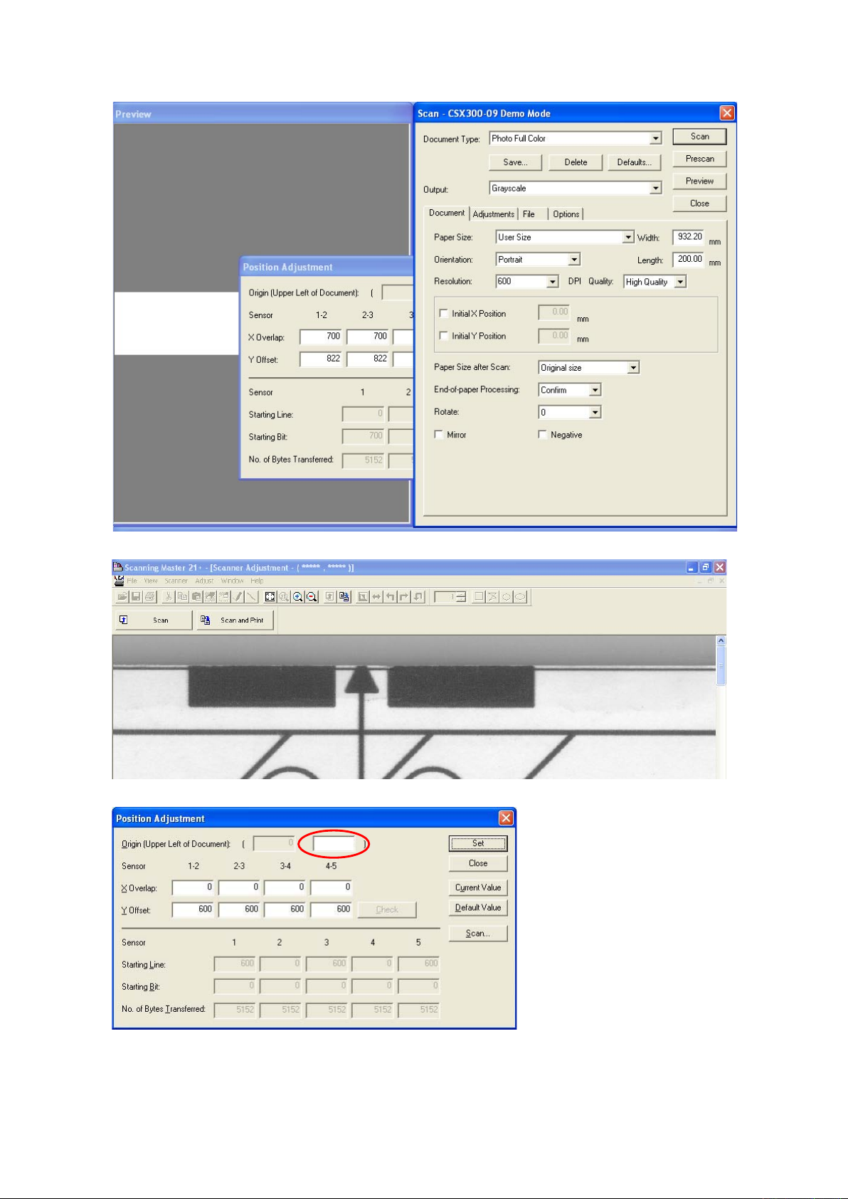
9. ADJUSTMENTS USING THE SOFTWARE
(12) The following dialog box will appear. Then click the "Scan" button.
(13) Zoom in to the top center circle using the zoom button.
(14) Click anywhere within the Origin box. The crosshairs cursor appears in the Scanner Adjustment window.
0
CSX300-UM-251-9370 9-22
Page 97
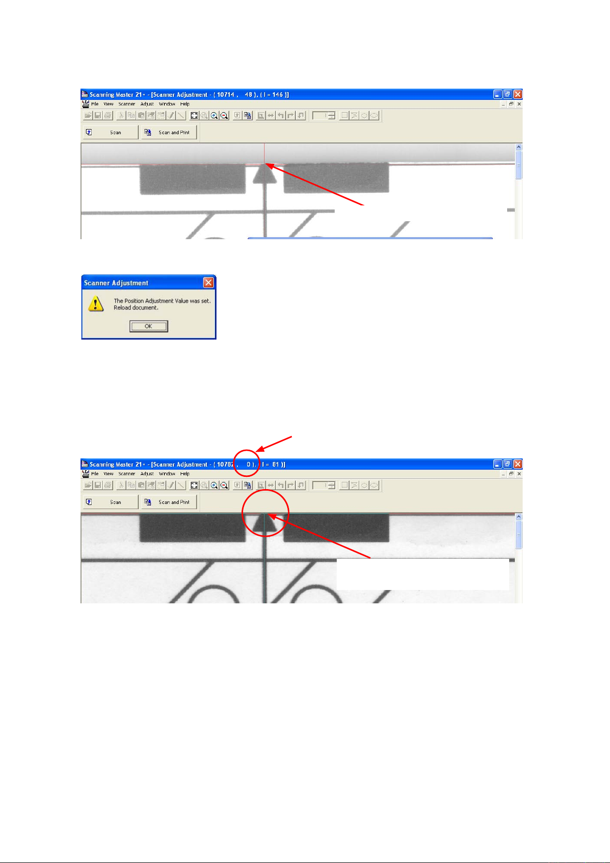
9. ADJUSTMENTS USING THE SOFTWARE
(15) When the crosshairs cursor appears in the Scanner Adjustment window, click on the center of the top
center edge with the crosshairs cursor.
Click here with the crosshairs cursor.
(16) Click the "Check" button, then click the "Set" button. The following dialog box will appear.
Click the "OK" button.
(17) Take out the CSX300 adjustment test chart from the scanner. And then reinsert the CSX300 adjustment
test chart to the scanner.
(18) Scan the offset target chart again.
Confirm that the starting point of the scanning is within the 7pixels from the top of window as shown
below.
Check the position by this indicator that the edge
is within the 7 pixels.
Position here with the mouse pointer,
and then check the position.
CSX300-UM-251-9370 9-23
Page 98
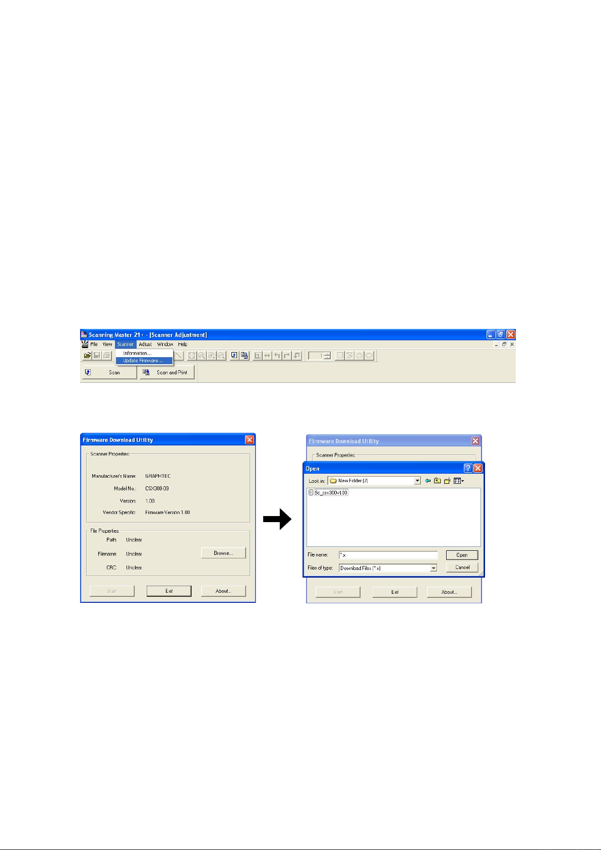
9. ADJUSTMENTS USING THE SOFTWARE
9.5 Downloading Firmware
This section describes how to download firmware (system programs) via the USB interface to the flash
memory provided on the data controller board, to which the boot program has been downloaded.
1. Items required to download firmware
• Sc_csx300vXXX.x file (Firmware)
• CSX300-09 scanner
• PC (Windows 2000/XP and an operating environment that provides USB 2.0 compatibility)
• OPS112 (Scanning Master 21+ Ver 6.40 or later)
• USB interface cable
2. Procedure
(1) Use the USB cable to connect the CSX300-09 and PC.
(2) Turn on the power for your PC.
(3) Run the Scanning Master 21+ (OPS112) in the adjustment mode. (see Section 9.1).
(4) When OPS112 starts, follow the steps given below to download the firmware.
(5) Select "Update Firmware" from the "Scan" menu to display the Download dialog box.
(6) Insert the floppy disk containing the firmware (filename: Sc_csx300vXXX.x) into the floppy disk drive,
click the "Browse" button on the Firmware Download dialog box, select the Sc_csx300vXXX.x, and click
the "Open" button.
(7) Click the "Start" button to begin downloading.
(8) After the download is complete, a message will appear. At this time, the paper and error LEDs on the
scanner should start flashing simultaneously.
After confirming this, turn off the power.
CSX300-UM-251-9370 9-24
Page 99

10. TROUBLESHOOTING
10.1 TROUBLESHOOTING
Cause Checkpoint Remedy
Lamps on the control
panel remain unlit.
The document is not
scanned, although
it is moved to the
scanning position.
The document is not
transported properly.
Confirm that the power switch has been
switched on.
Confirm that the power cable is properly
connected.
Confirm that the cable is properly connected
to the control device.
Confirm that the power outputs (+24 V, +5 V,
+3.3 V) are appropriate.
Other Replace the control panel.
Confirm that the PAPER LED is lit. Check the document detection photosensor.
Confirm that the USB cable is properly
connected.
Confirm that the USB cable is properly
connected within the scanner.
Confirm that the appropriate model has been
specified.
Other Replace the main control board.
Check for foreign objects in the document
scanning section.
10. TROUBLESHOOTING
Switch on the power switch.
Connect the cable properly.
Connect the cable properly.
Check the power supplies and replace if
necessary.
Replace the data controller board.
Connect the cable properly.
Connect the cable properly.
Specify the correct scanner model.
Open the center cover and remove foreign
objects.
The scanned data is
completely black.
Confirm that the roller rotates when you
press a control key.
Confirm that the feed motor is running. Check for anomalies around the motor.
Confirm that +24 V is output. Check the power supply and replace if
Other Replace the control boards.
Confirm that an appropriate white correction
value has been specified.
Confirm that the image sensor cables are
properly connected.
Confirm that the image sensor LEDs are lit. Check the +5 V power supply and replace it
Confirm that an appropriate value is specified
for “Intensity (Brightness)” in Scanning
Master 21+.
Check for anomalies around the control
boards.
necessary.
Replace the data control board.
Perform Calibration (white correction).
Confirm that the image sensor cables are
properly connected, with no broken wires.
if it is faulty.
Replace the data controller board.
Replace the CIS board.
Replace the image sensors.
Adjust “Intensity (Brightness)” in Scanning
Master 21+.
CSX300-UM-251-9370 10-1
Page 100

10. TROUBLESHOOTING
Cause Checkpoint Remedy
The scanned drawing
has undesired black
lines.
The scanned drawing
has undesired white
lines.
Part of the scanned
drawing is missing
(the scanned drawing
is horizontally
compressed).
Part of the
scanned drawing is
overlapped.
The image quality is
poor.
The PC does not
detect the scanner.
When placed on the
scanner, the paper
is moved beyond the
scanning section and
drops to the back of
the scanner.
Paper jam occurs. Check the transfer section for foreign objects. Remove foreign objects.
There is a difference
in color density
between the right-
and left-hand
portions of the
document scanned in
grayscale.
Clean the contact glass plates and replace if
necessary.
Confirm that calibration (white correction
has been properly performed.
Check the document hold-down plate for
stains.
Check whether the problem persists after
cleaning and adjustments.
Check the contact glass plates for dust and
damage.
Confirm that calibration (white correction
has been properly performed.
Confirm that the sensor X overlaps and Y
offsets are appropriate.
Confirm that the sensor X overlaps and Y
offsets are appropriate.
Check whether any of the contact glass
plates is dirty.
Confirm that the image resolution is
appropriate.
Confirm that the scanner has been turned
on.
Confirm that the PC has detected the USB
properly.
Check the cable for broken wires, shorting,
and bent connector pins.
Confirm with other PC.
The media sensors do not function properly. Clean the media sensor.
The sensor color density has not been
properly corrected.
Confirm that calibration (white correction
has been properly performed.
Clean the contact glass plates and replace if
necessary.
Clean the image sensors.
)
Perform calibration from the beginning (white
correction).
Clean the feed rollers.
Replace the image sensors.
Clean the contact glass plates and replace if
necessary.
)
Perform calibration from the beginning (white
correction).
Align the sensor joints.
Align the sensor joints.
Use purified water or alcohol to clean the
contact glass plate(s). (Do not use chemical
solvents.)
Select an appropriate resolution.
Turn on the scanner.
Reattach the USB cable, set it up, and
reinstall the USB driver.
Replace the cable.
Replace the main board if the USB port is
not detected.
Check the sensor cable for contact with other
cables.
Replace one or both media sensors.
Adjust color density.
)
Perform calibration from the beginning (white
correction).
CSX300-UM-251-9370 10-2
 Loading...