

Page 1

COLOR IMAGE SCANNER
SERVICE MANUAL
CS2000-UM-251-04-9370
Page 2

HISTORY OF REVISIONS
No. Date issued Description of revision Page Edition
1 03.03.16 First Printing All 01
2 04.02.16 Contents of the 2nd cautions corrected. 8-3, 8 -4 02
3 05.03.09 Part number for main board corrected. 14-14 03
4 05.06.23 Part number for CS Retaining Plate-JED corrected. 6-1,14-7 04
CS2000-UM-251-9370 i
Page 3

CS2000-UM-251-9370 ii
CONTENTS
1. OVERVIEW
1.1 Features .......................................................................................................................................1-1
1.2 Standard Specications ...............................................................................................................1-2
1.3 External View ...............................................................................................................................1-3
1.4 System Requirements ..................................................................................................................1-4
2. PART NAMES AND FUNCTIONS
2.1 Part Names and Functions...........................................................................................................2-1
3. PREPARING TO OPERATE THE SCANNER
3.1 Assembling the Scanner ..............................................................................................................3-1
3.2 Connecting the Scanner to a Power Supply ................................................................................3-3
3.3 Connecting the SCSI Cable .........................................................................................................3-4
Compatible Cables .....................................................................................................................3-4
Connection Procedure ................................................................................................................3-4
3.4 Setting the ID Number..................................................................................................................3-6
3.5 Turning the Scanner On or Off .....................................................................................................3-7
3.6 Attaching the Document Support Wires .......................................................................................3-7
4. OPERATION AND CONNECTION
4.1 Connecting the Scanner to a Computer .......................................................................................4-1
4.2 Checking the Interface Connection ..............................................................................................4-9
4.3 Installing the Scanning Master 21+ Application .........................................................................4-11
4.4 Document Types Compatible with the CS2000..........................................................................4-12
4.5 Loading a Document ..................................................................................................................4-13
4.6 Making the Document Hold-Down Unit Force Settings ..............................................................4-14
4.7 Using the Carrier Sheet..............................................................................................................4-15
4.8 Scanner Driver Software Compatibility with Windows 2000 ......................................................4-16
4.9 How to Obtain (Install) the ASPI Manager .................................................................................4-16
1. What you will need................................................................................................................4-16
2. How to obtain ASPI Manager................................................................................................4-16
3. How to install ASPI Manager ................................................................................................4-16
4.10 Checking the ASPI Layer ..........................................................................................................4-17
4.11 Checking Windows 2000 ASPI32 Status and Starting the Software.........................................4-18
4.12 Changing the Transfer Rate with the AVA-2915LP (Ultra SCSI-compliant) Card......................4-21
4.14 Factory Settings ........................................................................................................................4-23
DIP Switch ................................................................................................................................4-23
ID Number ................................................................................................................................4-23
5. DAILY MAINTENANCE
5.1 Removing and Mounting the Document Hold-Down Unit.............................................................5-1
5.2 Cleaning the Document Hold-Down Unit .....................................................................................5-3
5.3 Cleaning the Image Sensors ........................................................................................................5-4
5.4 Cleaning the Paper Sensors ........................................................................................................5-6
5.5 Removing a Jammed Document ..................................................................................................5-7
6. RECOMMENDED PARTS LIST
Page 4

CS2000-UM-251-9370 iii
7. LIST OF JIGS AND TOOLS
7.1 Jigs ...............................................................................................................................................7-1
7.2 Tools.............................................................................................................................................7-1
7.3 Other ............................................................................................................................................7-1
8. DISASSEMBLING AND ADJUSTING MECHANICAL PARTS
8.1 Considerations before starting disassembly ................................................................................8-1
8.2 Document Hold-down Unit ...........................................................................................................8-2
8.3 CS Retaining Plate .......................................................................................................................8-4
8.4 Side Covers..................................................................................................................................8-5
8.5 Top Cover.....................................................................................................................................8-6
8.6 Front Cover ..................................................................................................................................8-7
8.7 Rear Cover ...................................................................................................................................8-8
8.8 Large and Small Bottom Plates....................................................................................................8-9
8.9 Main Board .................................................................................................................................8-10
8.10 Power Boards............................................................................................................................8-12
8.11 CIS (Charge Coupled Device Imaging Semsor) Boards A, B, and C........................................8-13
8.12 Cooling Fan ...............................................................................................................................8-14
8.13 Separator Plates .......................................................................................................................8-15
8.14 Pinch Roller Units......................................................................................................................8-17
8.15 Front Guide ...............................................................................................................................8-19
8.16 Rear Guide ................................................................................................................................8-20
8.17 Control Panel ............................................................................................................................8-21
8.18 Cover Open Sensor ..................................................................................................................8-22
8.19 Front and Rear Paper Detection Sensors .................................................................................8-23
8.20 Motor .........................................................................................................................................8-25
8.21 Pulleys.......................................................................................................................................8-27
8.22 Drive Rollers..............................................................................................................................8-28
8.23 Image Sensor Unit ....................................................................................................................8-29
Replacing the Entire Image Sensor Unit...................................................................................8-29
Replacing the Glass Base Unit Only.........................................................................................8-32
9. BOARDS AND ELECTRICAL COMPONENTS
9.1 Wiring Diagrams...........................................................................................................................9-1
Overall Conguration ..................................................................................................................9-1
Component Layout on the Main Board .......................................................................................9-2
Power Unit Wiring .......................................................................................................................9-3
9.2 Power Supply Unit........................................................................................................................9-4
1. Checking Voltage Levels ........................................................................................................9-4
9.3 Main Control Board ......................................................................................................................9-5
1. Precautions for replacing the main board ...............................................................................9-5
2. Checking voltage levels ..........................................................................................................9-5
3. LED status ..............................................................................................................................9-5
4. Replacing the main board.......................................................................................................9-5
9.4 At-a-glance Guide to Adjustment Functions.................................................................................9-7
Key operations............................................................................................................................9-7
9.5 Downloading Firmware ................................................................................................................9-8
1. Items required to download rmware......................................................................................9-8
2. Procedure ...............................................................................................................................9-8
Page 5

9.6 Test Mode.....................................................................................................................................9-9
1. Procedure ...............................................................................................................................9-9
10. ADJUSTMENTS USING THE SOFTWARE
10.1 Starting the Software.................................................................................................................10-1
10.2 Preparations before Making Adjustments .................................................................................10-3
10.3 Preparing a Test Chart ..............................................................................................................10-4
10.4 Making Adjustments ..................................................................................................................10-5
Scanner Calibration ..................................................................................................................10-5
1. Calibration (white correction) ................................................................................................10-5
2. Feed distance adjustment.....................................................................................................10-7
3. Position adjustment ..............................................................................................................10-9
4. Shading (undesired color line removal) ..............................................................................10-14
5. Shading (undesired gray line removal) ...............................................................................10-17
10.5 Resolution adjustment check ..................................................................................................10-20
1. Paper-feed distance accuracy check..................................................................................10-20
2. Image-sensor offset (joint accuracy)...................................................................................10-20
3. Offset check........................................................................................................................10-20
4. Resolution check ................................................................................................................10-20
5. Color correction (using a color correction sheet) ................................................................10-21
11. TROUBLESHOOTING
12. SCHEMATIC DIAGRAMS
12.1 Control Board ............................................................................................................................12-1
13. OPTION
13.1 Basket Assembly Procedure (PG0010).....................................................................................13-1
Parts List...................................................................................................................................13-1
Assembly Procedure.................................................................................................................13-1
14. PARTS LIST
14.1 Parts List ...................................................................................................................................14-1
14.2 External Casing 1 ......................................................................................................................14-3
14.3 External Casing 2 ......................................................................................................................14-4
14.4 External Casing 3 ......................................................................................................................14-6
14.5 Document Hold-down Unit ........................................................................................................14-7
14.6 Pinch Roller Unit .......................................................................................................................14-8
14.8 Drive Roller Unit ...................................................................................................................... 14-11
14.9 Sensor Unit .............................................................................................................................14-12
14.10 Board Unit ...............................................................................................................................14-13
14.11 Accessories .............................................................................................................................14-15
CS2000-UM-251-9370 iv
Page 6

1. OVERVIEW
1. OVERVIEW
1.1 Features
600-dpi optical resolution for high-precision image scanning
Scanning with an optical resolution of 600 dpi allows even complex and difcult-to-scan documents,
such as CAD drawings, electronic les, and mapping data to be scanned rapidly and with high precision.
Scanning Master 21+ (scanner software included as a standard accessory) can be used to adjust the
resolution in ve levels (200 dpi to 800 dpi) to suit the scanned document.
Compatible document widths range from 210 mm to 1000 mm
Compatible with document sizes from ISO A4 up to ANSI E
Capable of color and grayscale scanning
Capable of scanning in color (24-bit color, 8-bit color) or grayscale (256 shades)
Capable of reading long-axis data
Long-axis images are supported with a maximum length of approximately four meters each.
Compact and lightweight design
A compact design was achieved by using a document travel system that employs closely-adhered image
sensors in the sensor unit (ve rows arranged in a zigzag pattern).
Image-processing functions
Use of the scanning software provided lets you set image-processing functions for the scanning of a
document.
Interface
The interface conforms to the SCSI-2 standard.
CS2000-UM-251-9370 1-1
Page 7

CS2000-UM-251-9370 1-2
1. OVERVIEW
1.2 Standard Specifications
Item CS2000
Document size ANSI E to ISO A4 (all sizes centered)
Effective scanning
area
Document thickness 1.5 mm or less (including the carrier sheet)
Optical resolution 600 dpi
Interpolated resolution Main scanning direction : 200 dpi, 300 dpi, 400 dpi, 600 dp
Main scanning system Contact image sensor system (Five A4 sensors in a zigzag pattern)
Sub scanning system Document travel (sheet through) system
Scanning speed*2 Monochrome: Approx. 1.3 ms/line
Scanning precision *3 ±0.1%, ±5 pixels
Gradation Monochrome: Bilevel, intermediate tones (dithering, error diffusion)
Light source LED (RGB)
Interface SCSI-2
Output Image data
Rated power supply 100 to 120/200 to 240 VAC ±10%, 50/60 Hz
Operating
environment
Power consumption 125 VA or less
External dimensions
(approx.)
Weight Approx. 48 kg (including stand)
Standards UL, FCC Class A (USA); CE Marking (EU)
Width : 914 mm (max. 1000 mm)
Length : 1189 mm (capable of long-length scanning) *1
Secondary scanning direction : 200 dpi, 300 dpi, 400 dpi, 600 dpi,
800 dpi
3.8 inch/s at 200 dpi
1.9 inch/s at 400 dpi
1.26 inch/s at 600 dpi
Color: Approx. 3.9 ms/line
1.28 inch/s at 200 dpi
0.64 inch/s at 400 dpi
0.42 inch/s at 600 dpi
Gray : 256 shades
Color: 8-bit, 24-bit
Temperature: 10˚C to 35˚C, Humidity: 35% to 80% RH (no condensation)
1205 X 1020 X 600 mm (WXHXD) (including stand)
* 1 Documents up to approximately 16 m in length (driver software limitation) can be scanned. However, the actual
document length that can be scanned is limited by the available memory (hard disk or other data storage device)
of the computer to which the scanner is connected, and also by the grade of the medium being scanned.
2
Excluding data-transfer time
*
3
Notes on scanning precision
*
Scanning precision may vary slightly depending on the grade and thickness of the medium being scanned, and on
the operating conditions. The precision figures above were measured under the operating conditions described
below.
• Test chart used : Mylar sheet #200
• Guaranteed precision conditions : Temperature 20 ±3˚C; humidity: 60% ±10% RH
• Guaranteed scanning precision range : 1189 mm x 841 mm
• Document hold-down unit setting : Standard
Page 8
CS2000-UM-251-9370 1-3
1. OVERVIEW
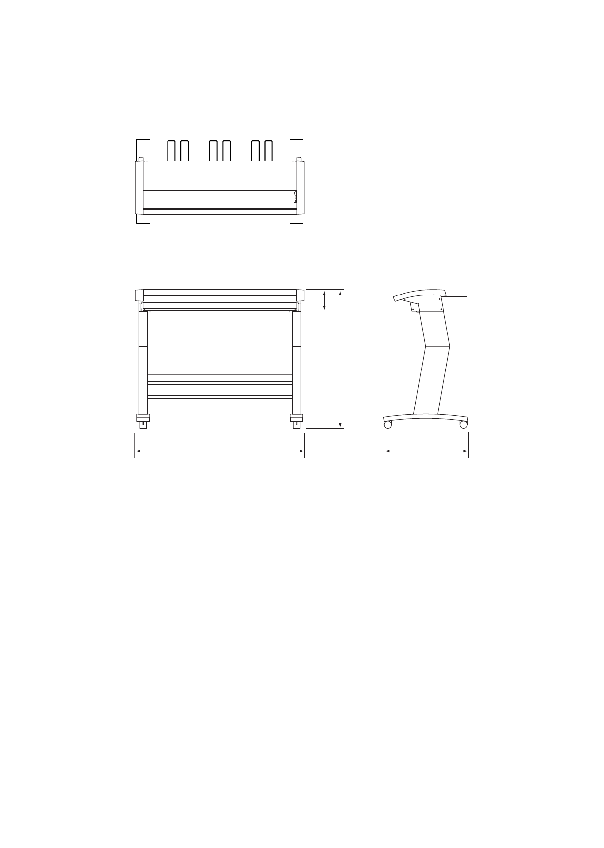
1.3 External View
156
1020
1205
600
External Dimensions of the CS2000
Unit : mm
Dimensional precision error : ±5 mm
Page 9

1. OVERVIEW
1.4 System Requirements
The minimum system requirements for running the scanner’s hardware and software are listed below.
Operating system: Windows 95/98/Me, Windows NT 4.0, Windows 2000 or later
CPU: Pentium 133 MHz or higher
Memory: 32 MB or more
Monitor: 1024 × 768 pixels, 256 colors or more
Enough disk space to store data
Mouse
SCSI board by Adaptec
Recommended environment
For binary monochrome data
CPU: Pentium 200 MHz or higher
Memory: 64 MB or more
SCSI board by Adaptec (PCI type)
For grayscale data
CPU: Pentium III 550 MHz or higher
Memory: 256 MB or more
Monitor: 1024 × 768 pixels, High Color or higher resolution
SCSI board by Adaptec (PCI type)
For 8-bit color data
The system conguration should correspond to the recommended specications listed here, in order to ensure the
optimum capabilities of the scanner.
Use with a system conguration below the recommended specications will affect the scanning speed and prevent
the scanner from operating to its specied capabilities.
To edit an A1- size or larger grayscale document with a resolution of 400 dpi or higher, or an 8-bit color document,
you may need more than the recommended memory sizes above. Depending on the type of document, you may not
be able to scan in the document even if you increase the memory size.
CPU: Pentium III 866 MHz or higher
Memory: 512 MB or more
Monitor: 1024 × 768 pixels, True Color or higher
SCSI board by Adaptec (PCI type)
CS2000-UM-251-9370 1-4
Page 10
2. PART NAMES AND FUNCTIONS
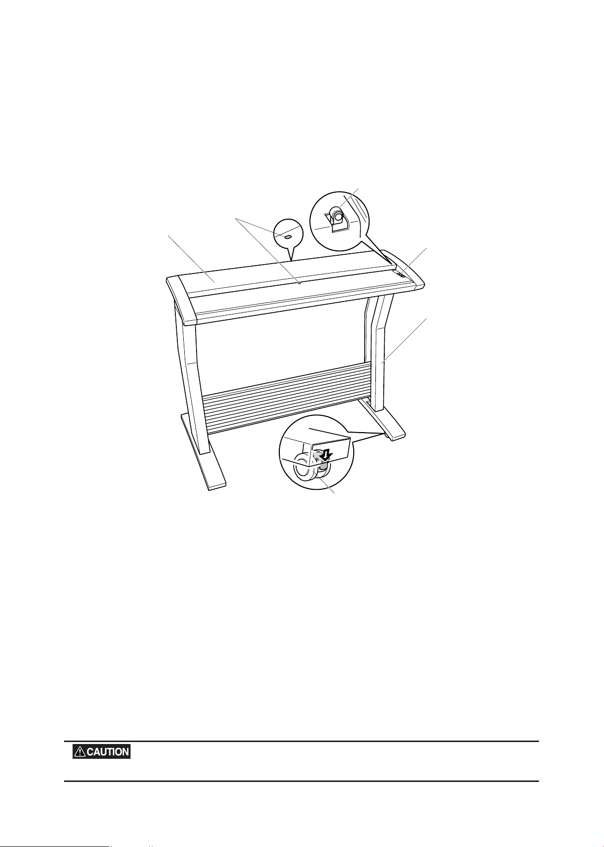
Cover sensor
Paper sensor
Top cover
Caster
Control panel
Stand
2.1 Part Names and Functions
Front View
2. PART NAMES AND FUNCTIONS
Top cover
Opening the top cover allows the document hold-down unit to be removed.
Cover sensor
This senses whether the top cover is open or closed, and interrupts scanner operation if the top cover is
opened during operation.
Stand
The stand unit is assembled for mounting of the scanner unit.
Casters
Release the lock on the casters to allow the unit to be moved.
Paper sensor
This senses whether a document is present in the scanner.
Do not touch the cover sensor or paper sensor.
CS2000-UM-251-9370 2-1
Page 11
CS2000-UM-251-9370 2-2
2. PART NAMES AND FUNCTIONS
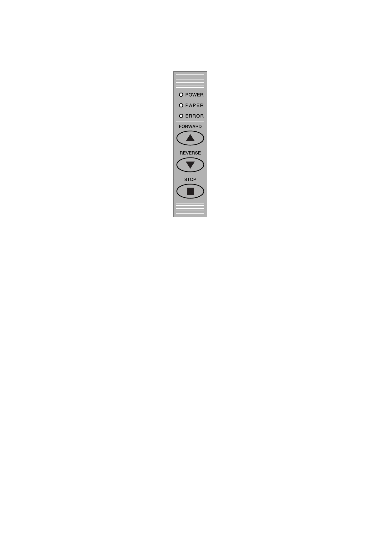
Control panel
POWER LED
Unlit : Is unlit while the scanner is turned off.
Lit : Lights (green) when the scanner is turned and remains lit while it is operating normally.
PAPER LED
Unlit : Normal status (Local status).
Lit : Lights (green) when the scanner enters Scan READY status.
Flashing : Flashes (green) while image data is being scanned.
ERROR LED
Lit : Lights (red) to indicate a hardware error.
Flashing : Flashes (red) when a document is detected during the self-test when the scanner is turned on or
when the scanning is suspended by pressing the STOP key.
Unlit : Normal status
FORWARD key
Advances the document into the scanner. When this key is pressed in Scan READY status, the Scan
READY status is cancelled and the document is ejected toward the rear of the scanner.
REVERSE key
Feeds the document toward you. When this key is pressed in Scan READY status, the Scan READY status
is cancelled and the document is ejected toward the front of the scanner.
STOP key
Compulsorily stops scanning of the document.
Page 12
CS2000-UM-251-9370 2-3
2. PART NAMES AND FUNCTIONS
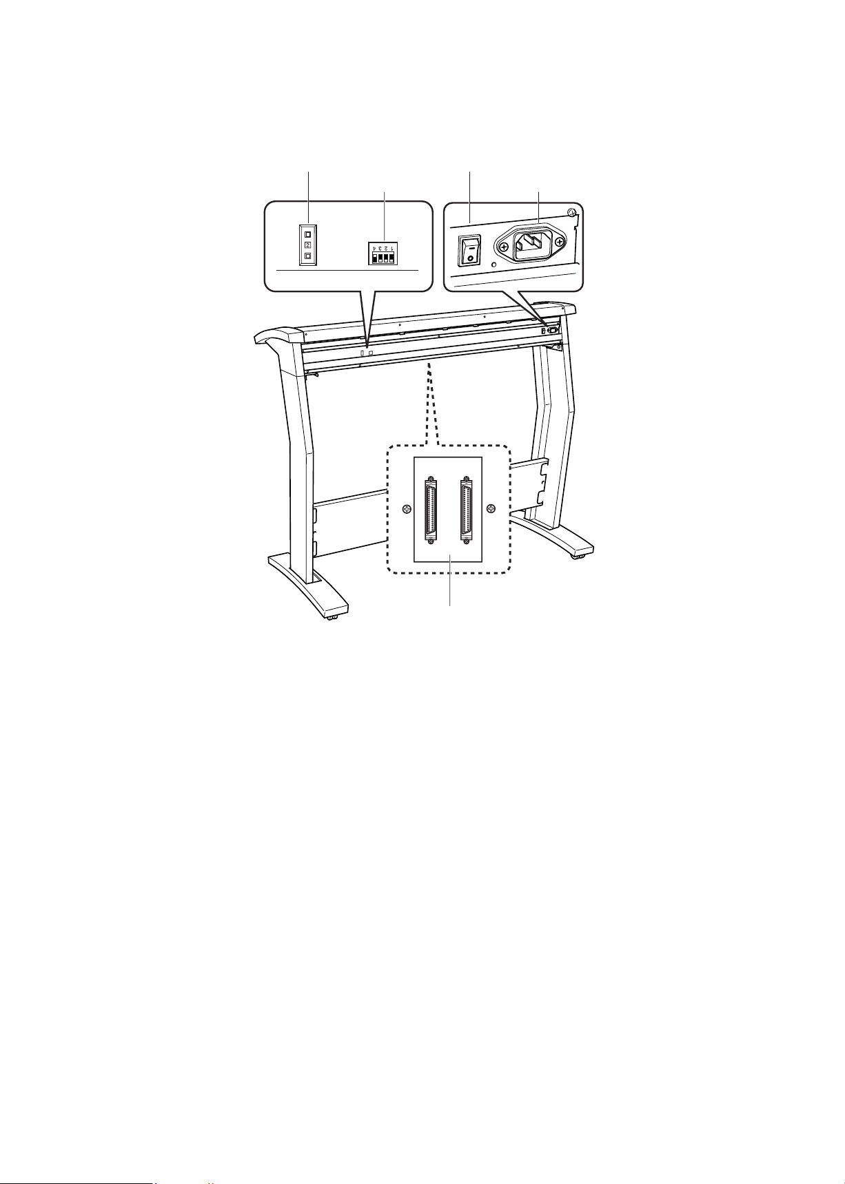
Rear View
SCSI-ID switches
DIP switch
Power switch
AC line inlet
SCSI connectors
SCSI-ID switches
Used to specify the ID numbers of the SCSI interfaces.
DIP switch
Used to set the scanner’s functions.
Power switch
Controls the on/off status of the power supply to the scanner.
AC line inlet
Connect the power cord’s female plug here.
SCSI connectors
Used to connect SCSI interface cables. The two connectors are connected in parallel inside the scanner.
Page 13
3. PREPARING TO OPERATE THE SCANNER
(1)
(2)
(3)
3. PREPARING TO OPERATE THE SCANNER
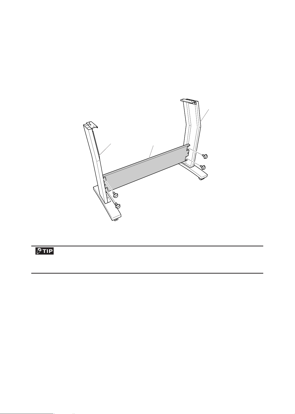
3.1 Assembling the Scanner
Assemble the stand before mounting the scanner unit. Eight bolts and an Allen wrench are provided with the
stand.
(1) Using the four bolts, loosely attach the center bar (3) to side stay R (1) and side stay L (2).
Attach the center bar loosely. Tighten the bolts securely after the scanner unit has been mounted on the
stand.
CS2000-UM-251-9370 3-1
Page 14
CS2000-UM-251-9370 3-2
3. PREPARING TO OPERATE THE SCANNER
Positioning pin
Side cover
Side cover
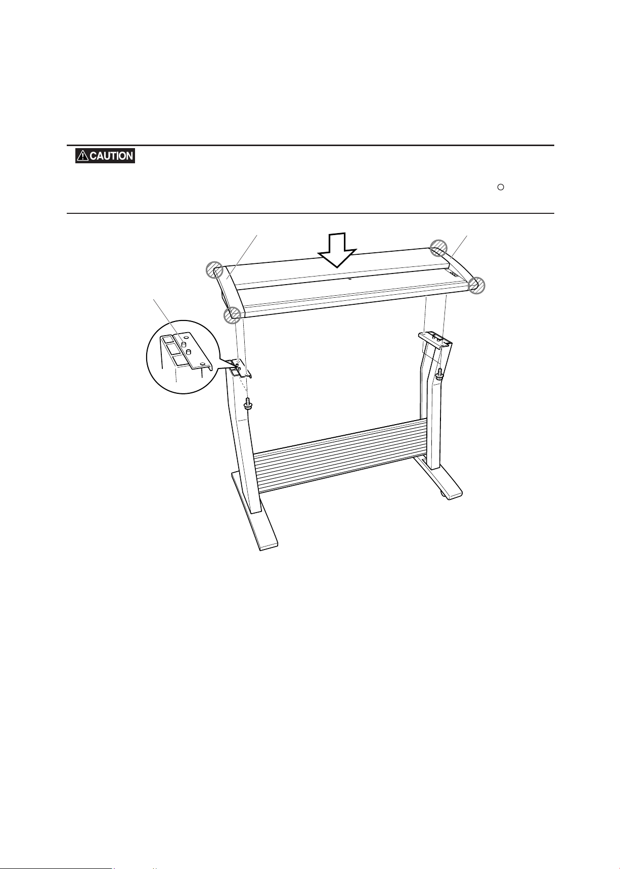
(2) Hold the scanner unit by the side covers on both sides, and mount the scanner so that the positioning
pins on the stand align with the positioning holes on the underside of the scanner. Secure using the four
bolts.
Holding the scanner by the rear part of the top cover may cause damage to the scanner or to the person doing the
installation. Always hold the scanner by the side covers, at the positions indicated by the shaded circles in the fig-
ure below.
(3) Fully tighten the four bolts on the center bar to secure the side stays (see the diagram for step (1)).
(4) Before beginning scanner operation, be sure to remove the plastic sheet from the bottom of the document
hold-down unit. Please refer to Section 8.2 “Document Hold-Down Unit” for the removal and mounting
procedures.
Page 15
CS2000-UM-251-9370 3-3
3. PREPARING TO OPERATE THE SCANNER
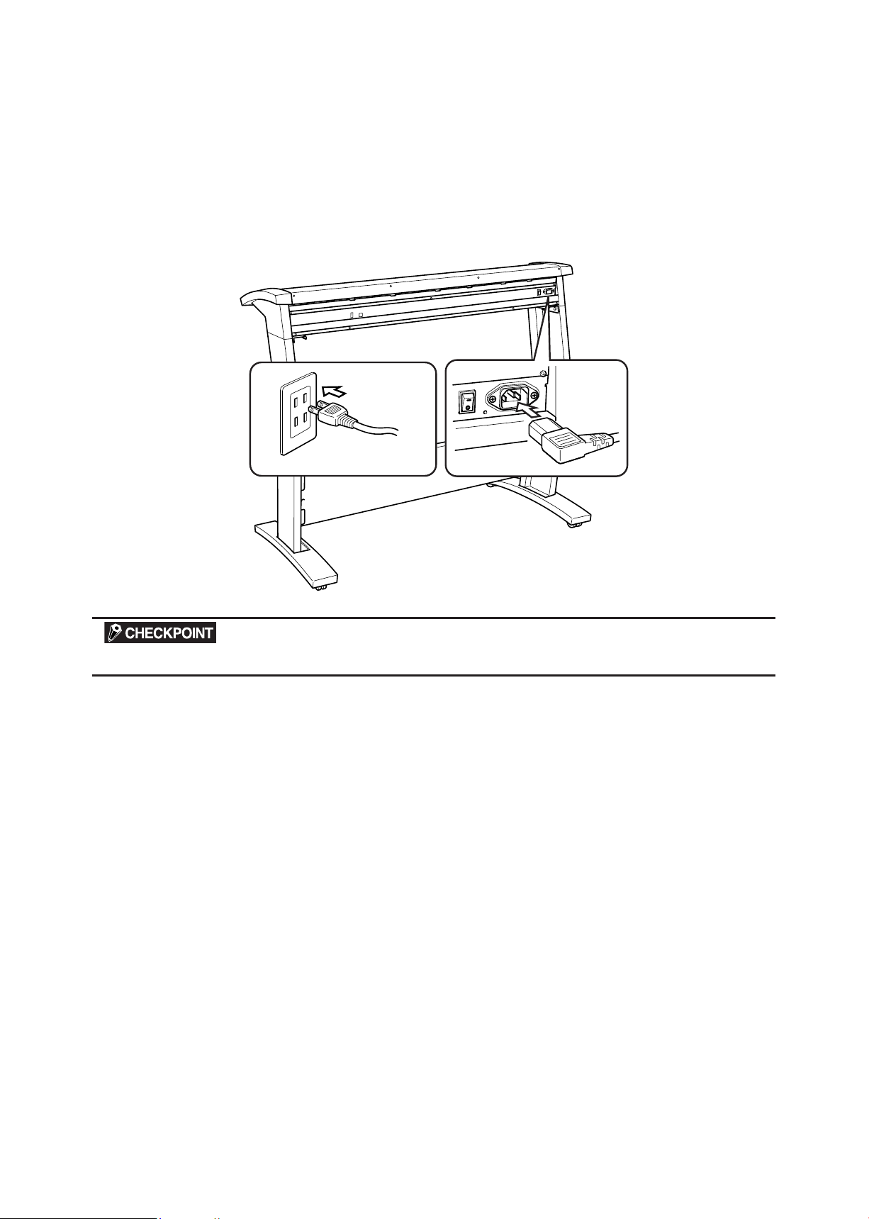
3.2 Connecting the Scanner to a Power Supply
Insert the female plug of the power cord provided into the scanner’s AC line inlet and insert its male plug into
an electrical socket supplying AC voltage.
Check that the scanner’s Power switch remains in the Off position until the connection of both the power cord
and SCSI interface cable has been completed.
Ensure that the scanner’s Power switch is in the Off position.
Page 16
CS2000-UM-251-9370 3-4
3. PREPARING TO OPERATE THE SCANNER
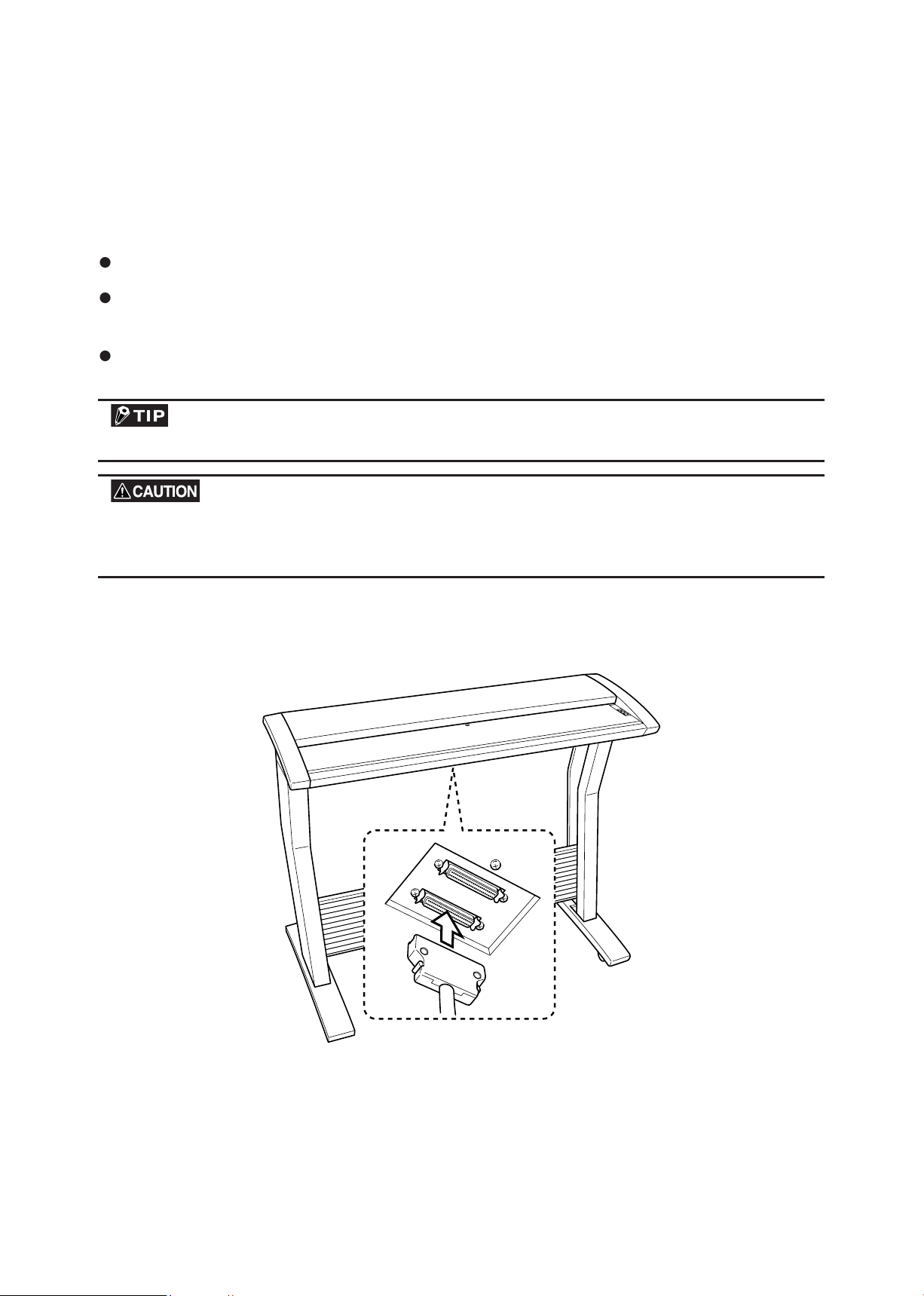
3.3 Connecting the SCSI Cable
Obtain a SCSI interface cable (optional) that is compatible with the computer to be connected.
Compatible Cables
The cable must have half-pitch pin-type 50-pin connectors.
To connect multiple SCSI devices in a daisy-chain* arrangement, the total cable length must be no longer
than three meters.
Among Graphtec cables, the SC0006 or SC0006 2M model can be used (depending on the shape of the
connector on the computer’s SCSI interface board).
* Daisy-chain: A method for connecting peripheral devices in a ring arrangement
The use of an incompatible cable may cause the scanner to malfunction or damage the interface.
If the cable comes into contact with the document, use the cable clamp provided as a standard accessory to fasten
the cable to the underside of the scanner.
Connection Procedure
(1) Insert one end of the SCSI cable’s into one of the two SCSI connectors on the scanner’s rear panel.
* Firmly insert the cable’s connector into the scanner’s SCSI connector until it locks into place.
Page 17
CS2000-UM-251-9370 3-5
3. PREPARING TO OPERATE THE SCANNER
SCSI cable
Cable clamp
1 2 3 4
4 3 2 1
ON
DIP switch’s bits
ON
OFF
Usually OFF
Terminator
Disable
Enable
(2) If the SCSI cable comes into contact with the document, use the cable clamp provided as a standard
accessory to fasten the cable to the underside of the scanner, at either the left or right side.
(3) Insert the cable’s other end into the computer’s connector.
(4) If this scanner will be a terminal within the network conguration, set Bit 4 of the DIP switch on the
scanner’s rear panel to enable the internal terminator function.
Turn off the scanner before changing a DIP switch setting.
The scanner comes with the Terminator setting of “Enable” as its factory-preset default.
Page 18
CS2000-UM-251-9370 3-6
3. PREPARING TO OPERATE THE SCANNER
2
3
2
1
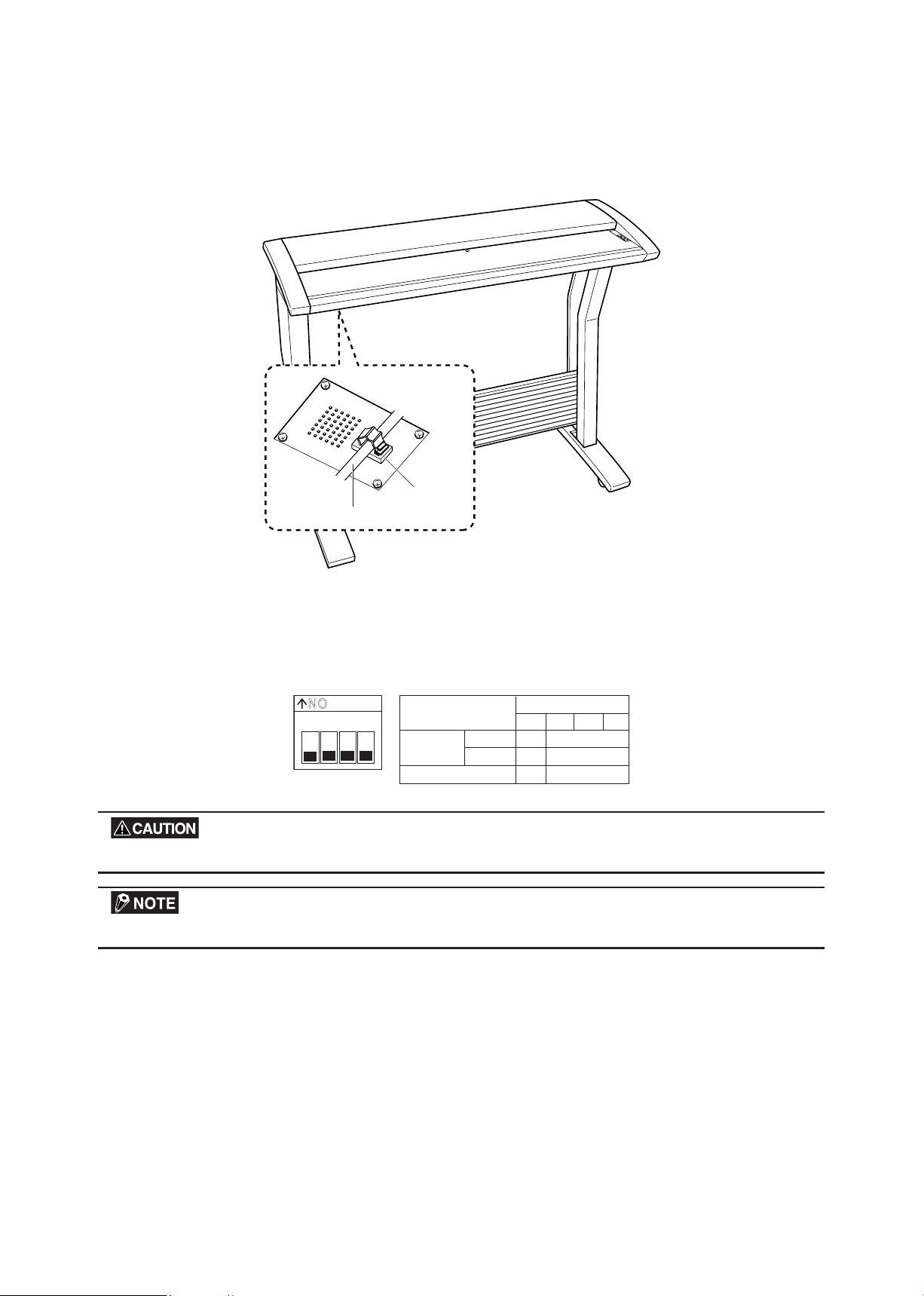
3.4 Setting the ID Number
The SCSI bus is designed to allow up to eight devices to be connected at the same time. As a result, a single
computer can be used to exchange data with multiple SCSI devices, including a scanner and disk drives.
Each device must be assigned an ID number (device number) to enable the devices to be distinguished on
the SCSI bus.
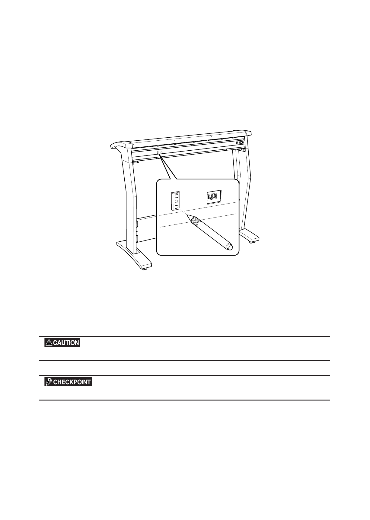
Using a mechanical pencil or other pointed object at the SCSI-ID switches on the scanner’s rear panel, set
the scanner’s ID number that corresponds to the host computer’s applications.
• The ID can be set from 0 to 7.
• The scanner’s default ID number is 2.
If the host computer cannot communicate with the scanner, rst check that both of the SCSI cable’s
connectors are rmly inserted. Note that the host computer and scanner cannot communicate if the scanner
shares the same ID as another device or its ID does not correspond to the host computer’s applications.
The ID number for the host computer is normally 7.
Turn off the scanner before setting the SCSI-ID number.
The scanner comes with the default SCSI-ID number of 2.
Page 19
CS2000-UM-251-9370 3-7
3. PREPARING TO OPERATE THE SCANNER
Document support wires
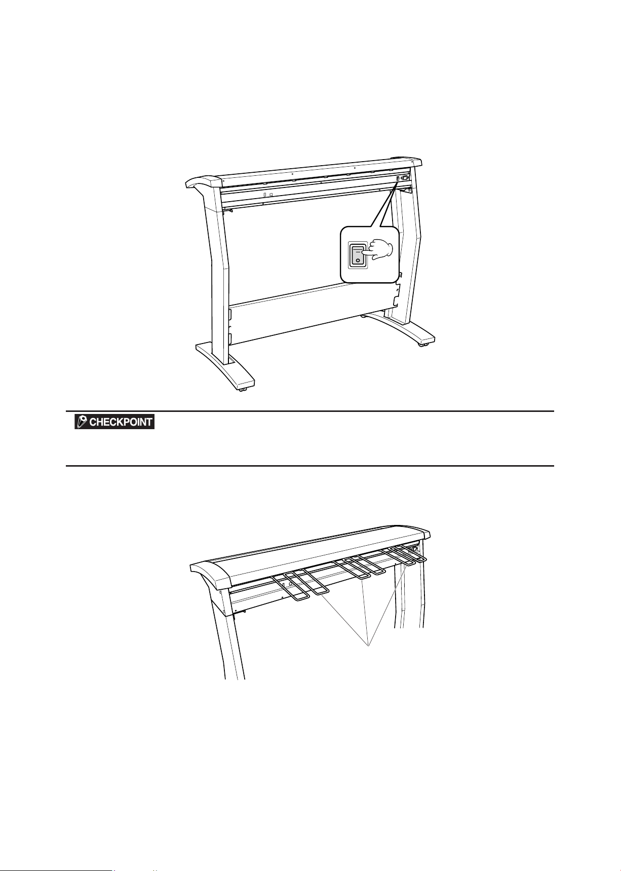
3.5 Turning the Scanner On or Off
Whenever the scanner’s Power switch is turned on, the POWER, PAPER, and ERROR lamps on the control
panel light up. When the scanner has been initialized, the POWER lamp lights up.
When resetting the scanner by turning it off then back on again, wait at least three seconds before turning it back
on.
3.6 Attaching the Document Support Wires
The document support wires should be attached when carrier sheets or heavy documents are scanned.
Page 20
3. PREPARING TO OPERATE THE SCANNER
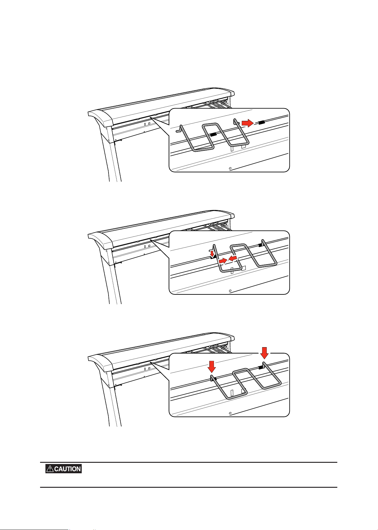
Attaching the document support wires
(1) Insert one end of the document support wire provided into the slot at the rear of the scanner.
(2) Squeeze the document support wire, and insert the other end.
(3) Press down on both sides of the document support wire.
(4) Attach the other document support wires in the same manner.
Detach the document support wires when moving or packing the scanner. Squeeze softly and lift them to detach.
CS2000-UM-251-9370 3-8
Page 21
4. OPERATION AND CONNECTION
4. OPERATION AND CONNECTION
4.1 Connecting the Scanner to a Computer
Before you can start connecting the scanner to the computer, you need to prepare (conrm) the computer
system’s environment.
(1) Conrm that the computer’s operating system has been properly installed.
(2) Conrm that a SCSI adapter has been connected to the computer.
(3) Conrm that the SCSI driver has been installed in the computer.
Connecting the CS2000 to a Computer for the First Time
For Windows 95 or Windows 95 Version a:
(1) After checking that the scanner and the computer are properly connected via the SCSI interface cable,
turn on the scanner rst and then turn on the computer.
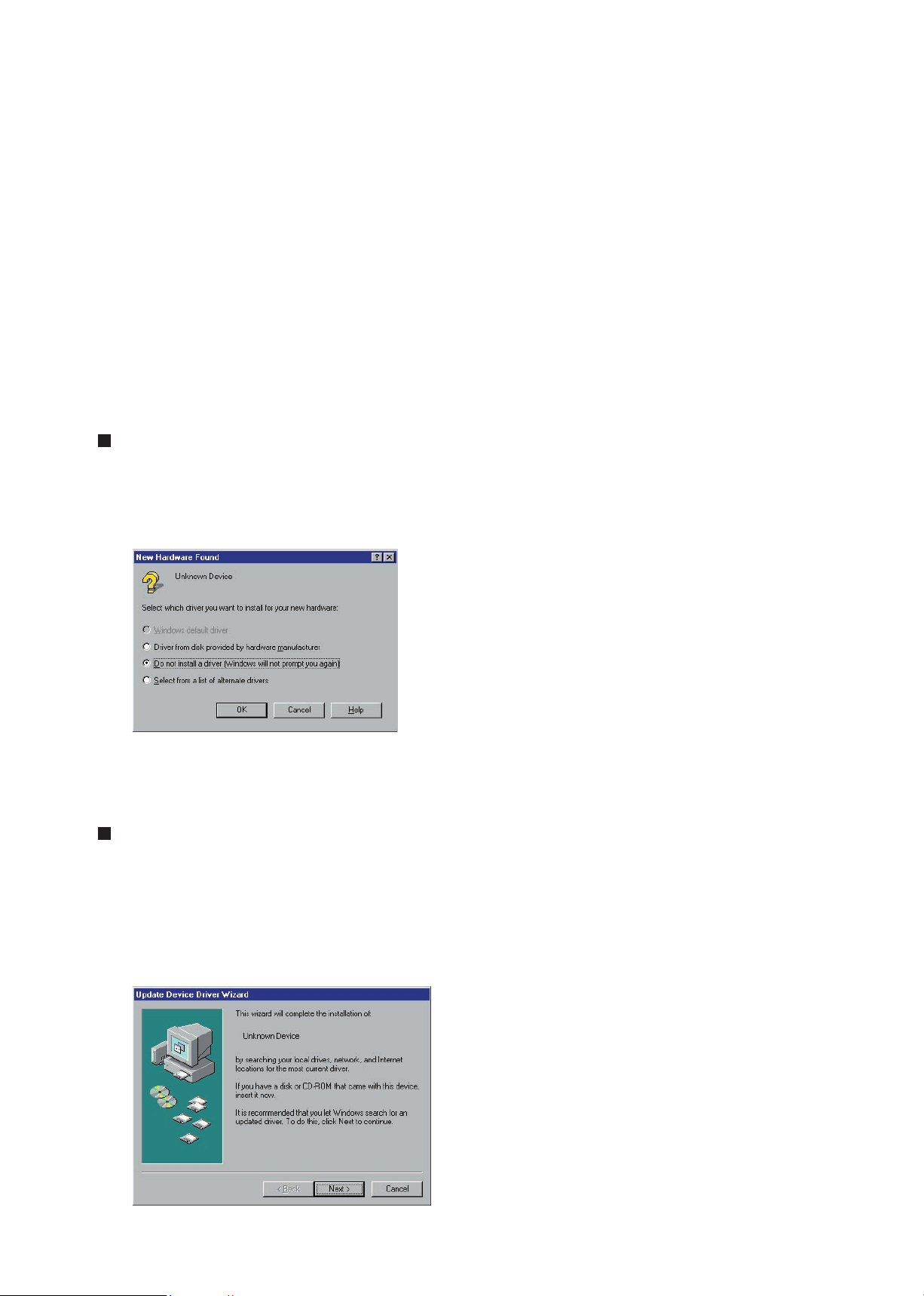
(2) When Windows 95 has been booted, the window below appears.
(3) Select ”Do not install a driver,” then click the “OK” button.
(4) The Windows 95 Desktop appears and the CS2000 is acknowledged by the computer.
For Windows 95 Version B:
(the actual screen displayed may be different from the one shown, depending on which version of Windows
95 you have)
(1) After checking that the scanner and the computer are properly connected via the SCSI interface cable,
turn on the scanner rst and then turn on the computer.
(2) When Windows 95 has been booted, the window below appears.
CS2000-UM-251-9370 4-1
Page 22
CS2000-UM-251-9370 4-2
4. OPERATION AND CONNECTION
(3) Click the Next button to initiate the computer’s search for a new driver.
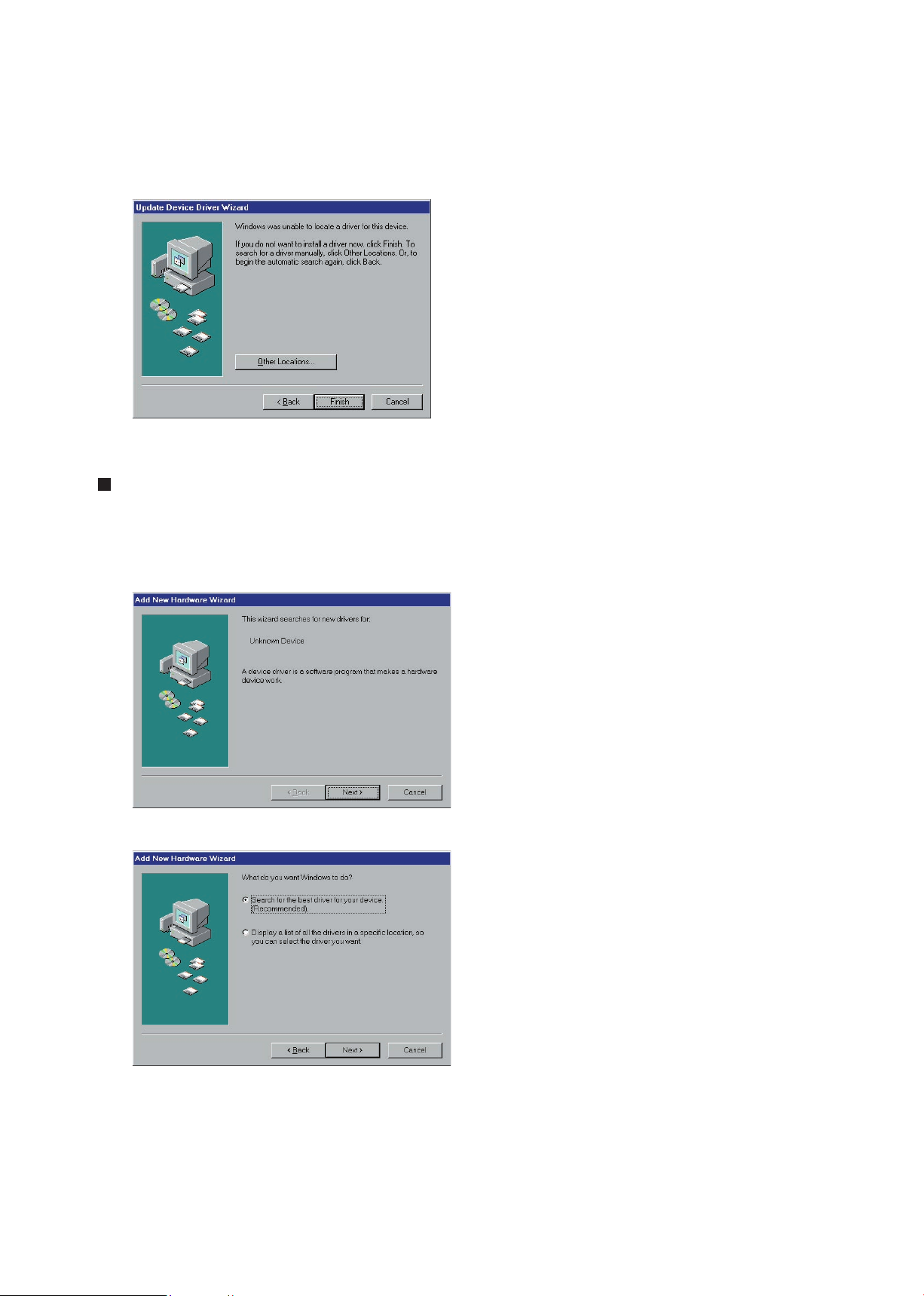
(4) When the new driver has been detected, the menu below appears. Click the Finish button.
(5) The Windows 95 Desktop appears and the CS2000 is acknowledged by the computer.
For Windows 98:
(1) After checking that the scanner and the computer are properly connected via the SCSI interface cable,
turn on the scanner rst and then turn on the computer.
(2) When Windows 98 has been booted, the window below appears.
(3) Click the Next button.
Page 23
CS2000-UM-251-9370 4-3
4. OPERATION AND CONNECTION
(4) Point to “Search for the best driver for your device” and then click the Next button.
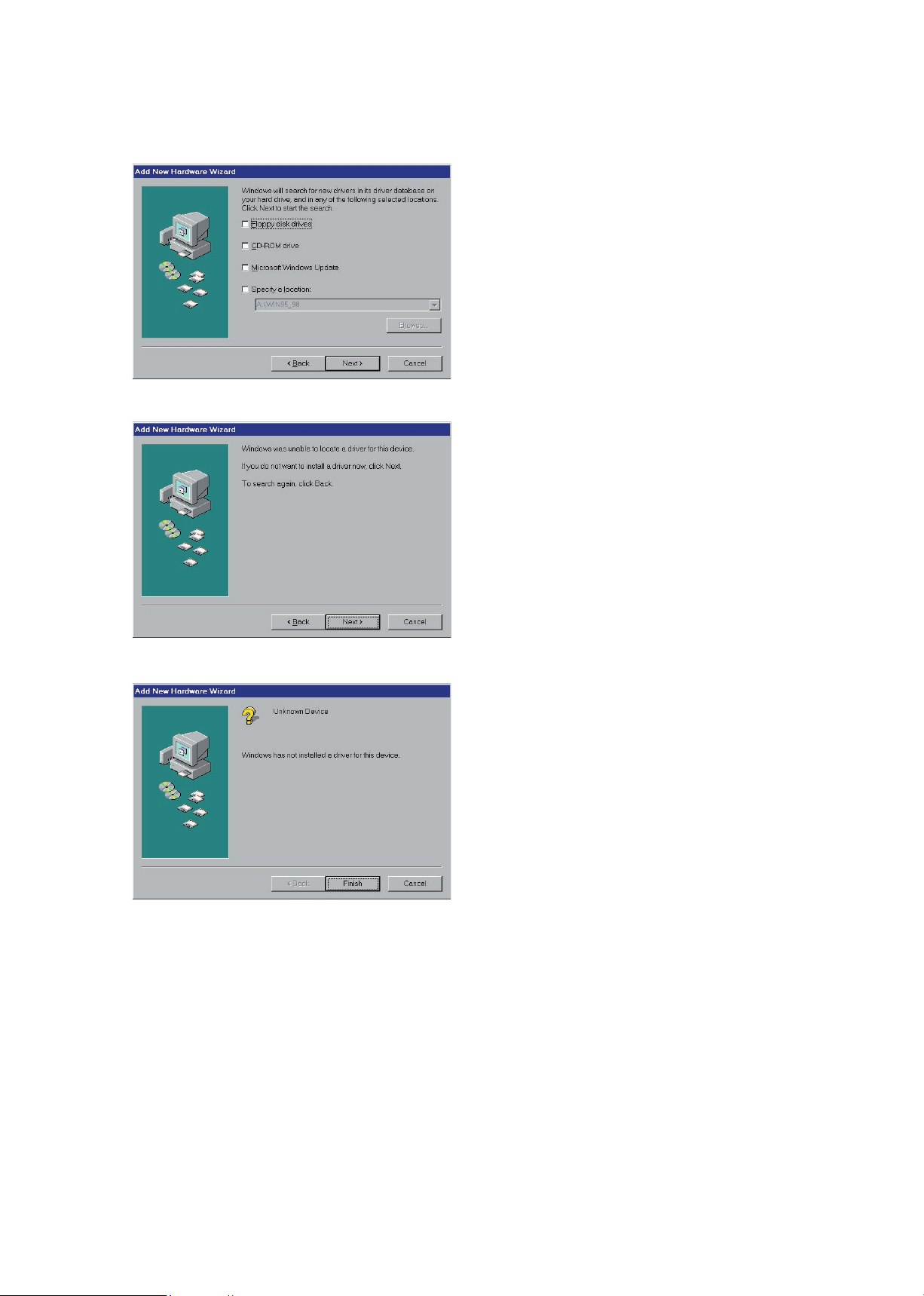
(5) Remove the check marks from all boxes and then click the Next button.
(6) Click the Next button.
(7) Click the Finish button.
(8) The Windows 98 Desktop appears and the CS2000 is acknowledged by the computer.
Page 24
CS2000-UM-251-9370 4-4
4. OPERATION AND CONNECTION
For Windows ME:
(1) Connect the CS2000 to the computer, turn on the CS2000 rst, and then turn on the computer.
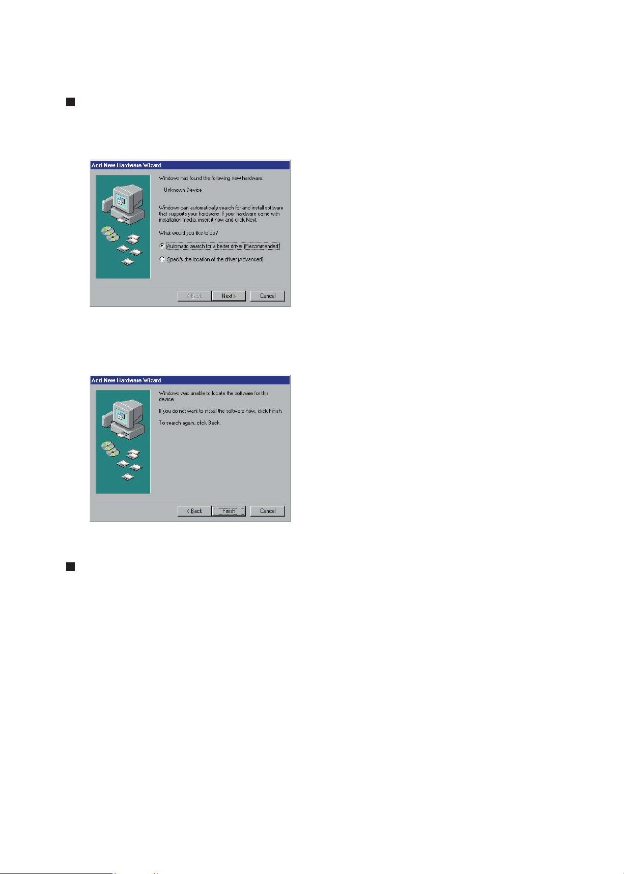
(2) Once Windows Me has started up, the window shown below is displayed.
(3) Click on “Next” to search for the driver.
(4) Upon completion of the search for the driver, the window shown below is displayed. Click on the “Finish”
button.
(5) The Windows Me desktop is displayed, and the CS2000 is recognized by the computer.
For Windows NT 4.0:
(1) After checking that the scanner and the computer are properly connected via the SCSI interface cable,
turn on the scanner rst and then turn on the computer.
Page 25
CS2000-UM-251-9370 4-5
4. OPERATION AND CONNECTION
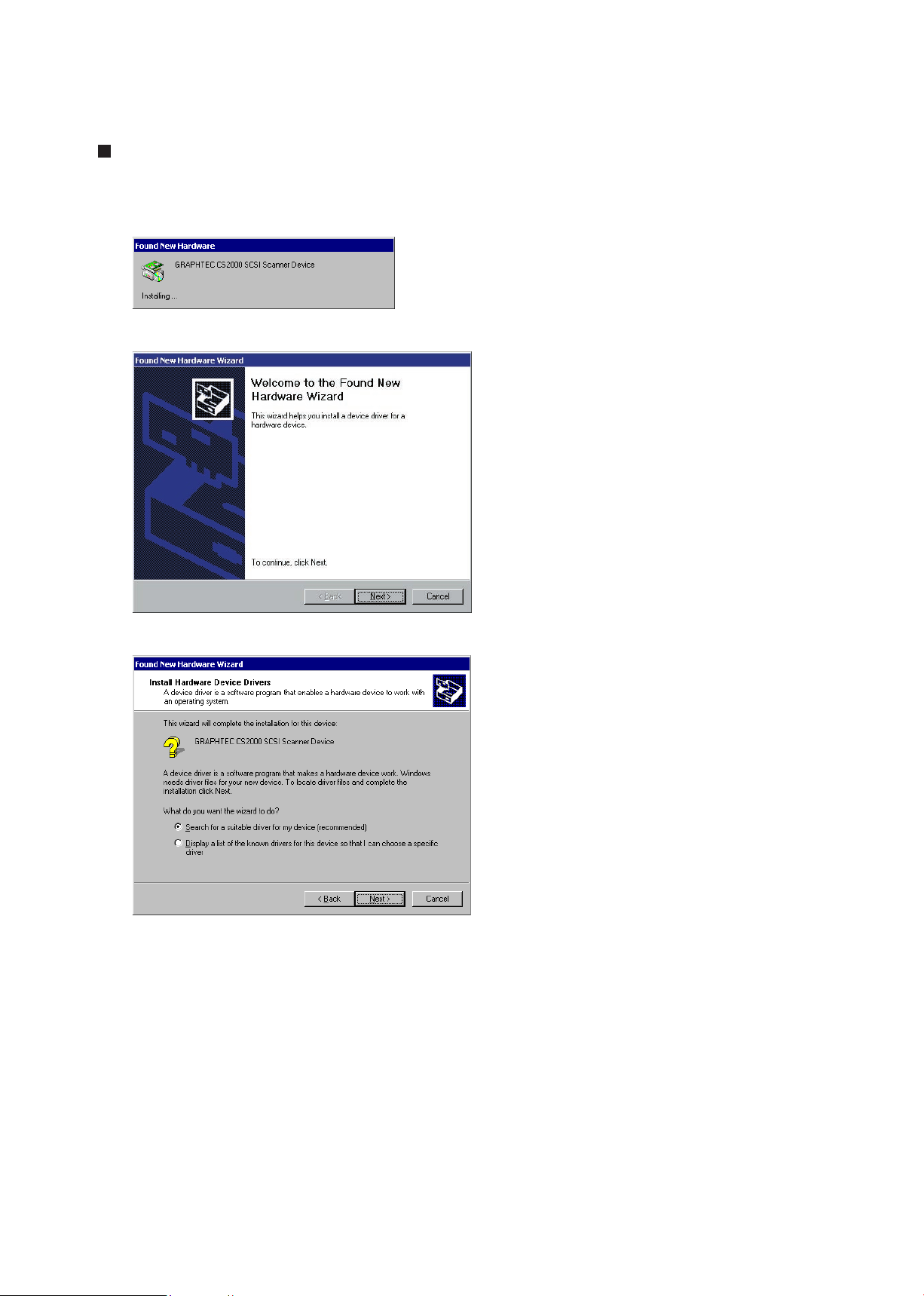
For Windows 2000
(1) After connecting the CS2000 to the computer, turn on the CS2000 and then turn on the computer.
(2) When Windows 2000 boots, the message below appears.
(3) Next, the Found New Hardware Wizard appears.
(4) Click the Next button to proceed to the menu for installing the driver.
Page 26
CS2000-UM-251-9370 4-6
4. OPERATION AND CONNECTION
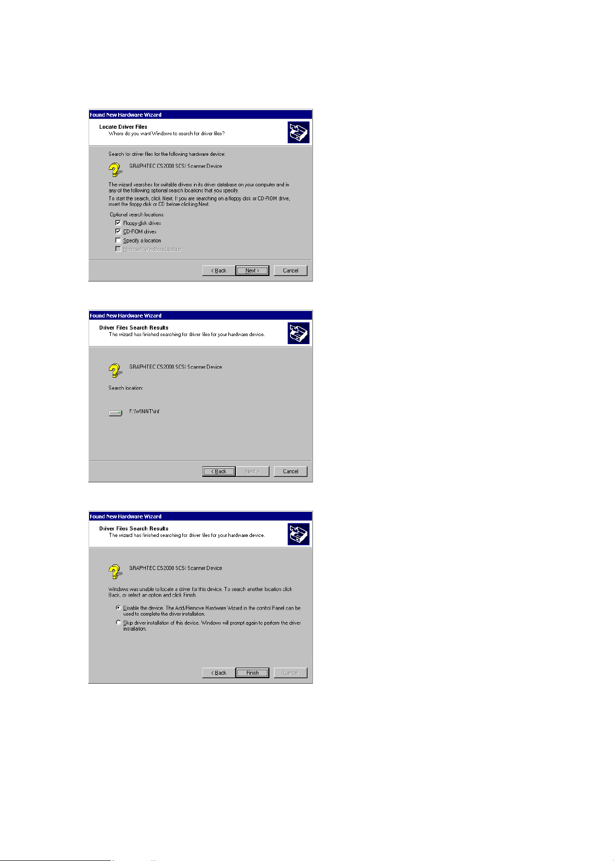
(5) Click the Next button to proceed to the Locate Driver Files menu shown below.
(6) Click the Next button to start searching for the driver les.
(7) When the wizard has nished its search, the menu below appears.
Insert a check in the “Disable the device” box, then click the Finish button.
(8) The Windows 2000 Desktop appears and the CS2000 is acknowledged by the computer.
Page 27
CS2000-UM-251-9370 4-7
4. OPERATION AND CONNECTION
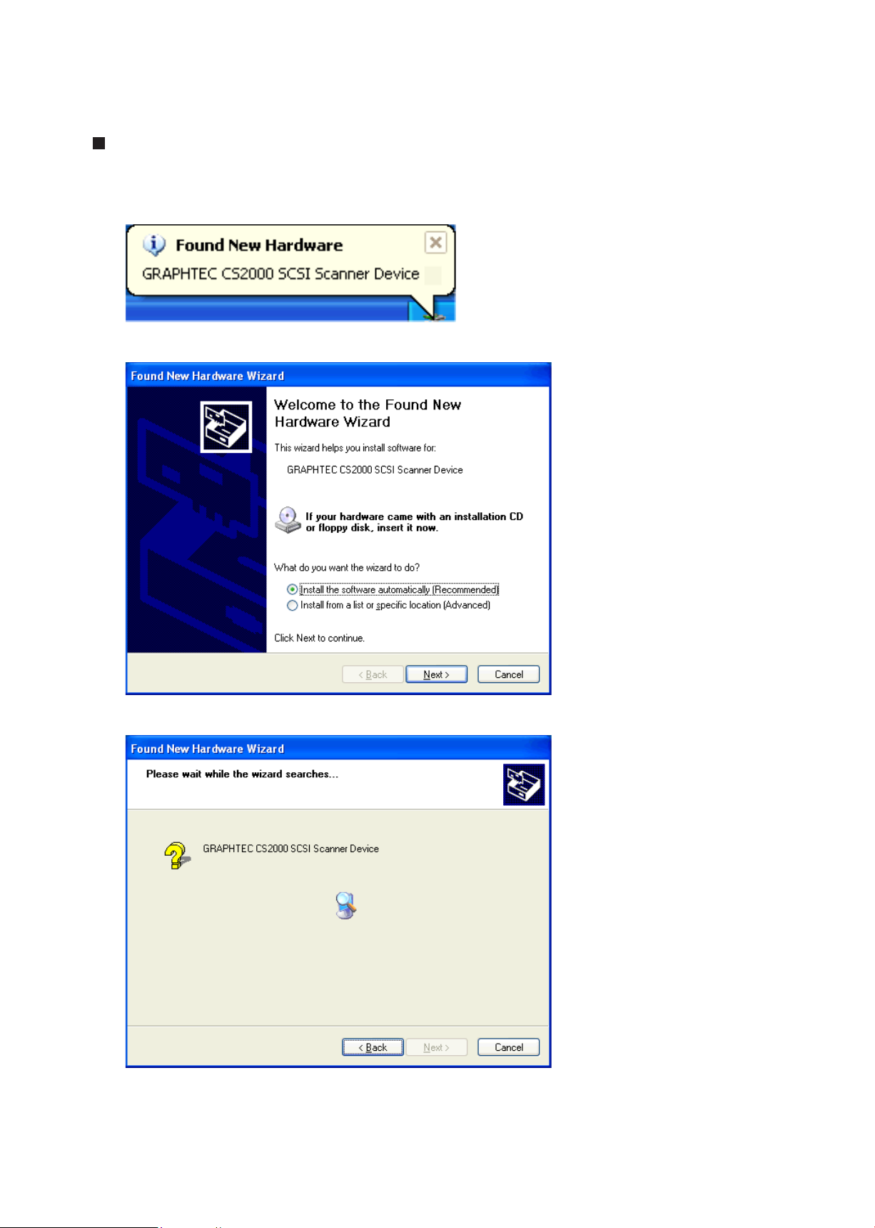
For Windows XP
(1) Connect the scanner to the computer, turn on the scanner rst, and then turn on the computer.
(2) When Windows XP starts up, the following window appears.
(3) Next, the Found New Hardware Wizard window appears.
(4) Click the Next button to proceed to the driver installation window.
Page 28
CS2000-UM-251-9370 4-8
4. OPERATION AND CONNECTION
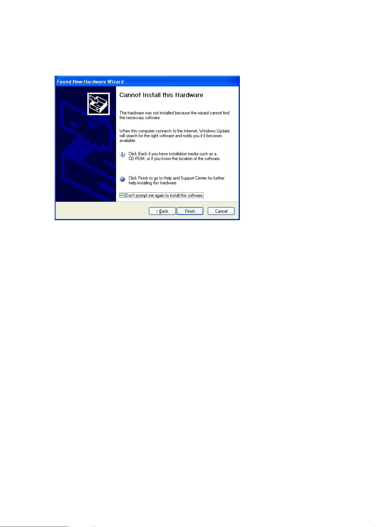
(5) Once the computer nds the driver, the following window appears.
Turn on the “Don’t prompt me again to install this software” check box. Then click the Finish button.
(6) The Windows XP desktop appears, and the scanner is recognized by the computer.
Page 29
CS2000-UM-251-9370 4-9
4. OPERATION AND CONNECTION
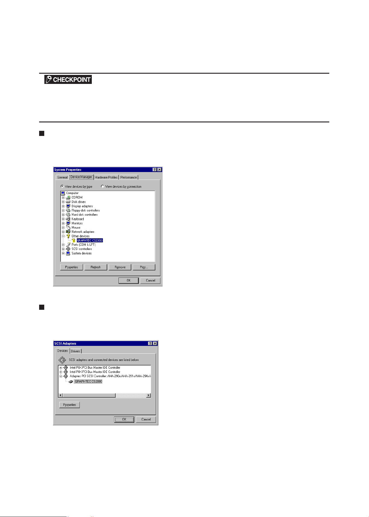
4.2 Checking the Interface Connection
If the scanner is connected to a system with Adaptec EZ- SCSI DELUXE* installed, the scanner will be recognized
under “Scanner” in the Device Manager.
* EZ-SCSI DELUXE is the software included with the SCSI adapter. For details, see the SCSI adapter instruction
manual.
For Windows 95/98/Me
Open the System window from within the Control Panel in My Computer.
Click on the Device Manager tab to display the list of installed devices. Conrm that the CS2000 is
recognized under “Other devices.”
For Windows NT 4.0:
From the Control Panel window in the My Computer folder, boot the SCSI adapter. Select the SCSI adapter
that is connected to the scanner by double-clicking it, then check that the scanner (CS2000) is listed below
the SCSI adapter and is thus acknowledged.
Page 30
CS2000-UM-251-9370 4-10
4. OPERATION AND CONNECTION
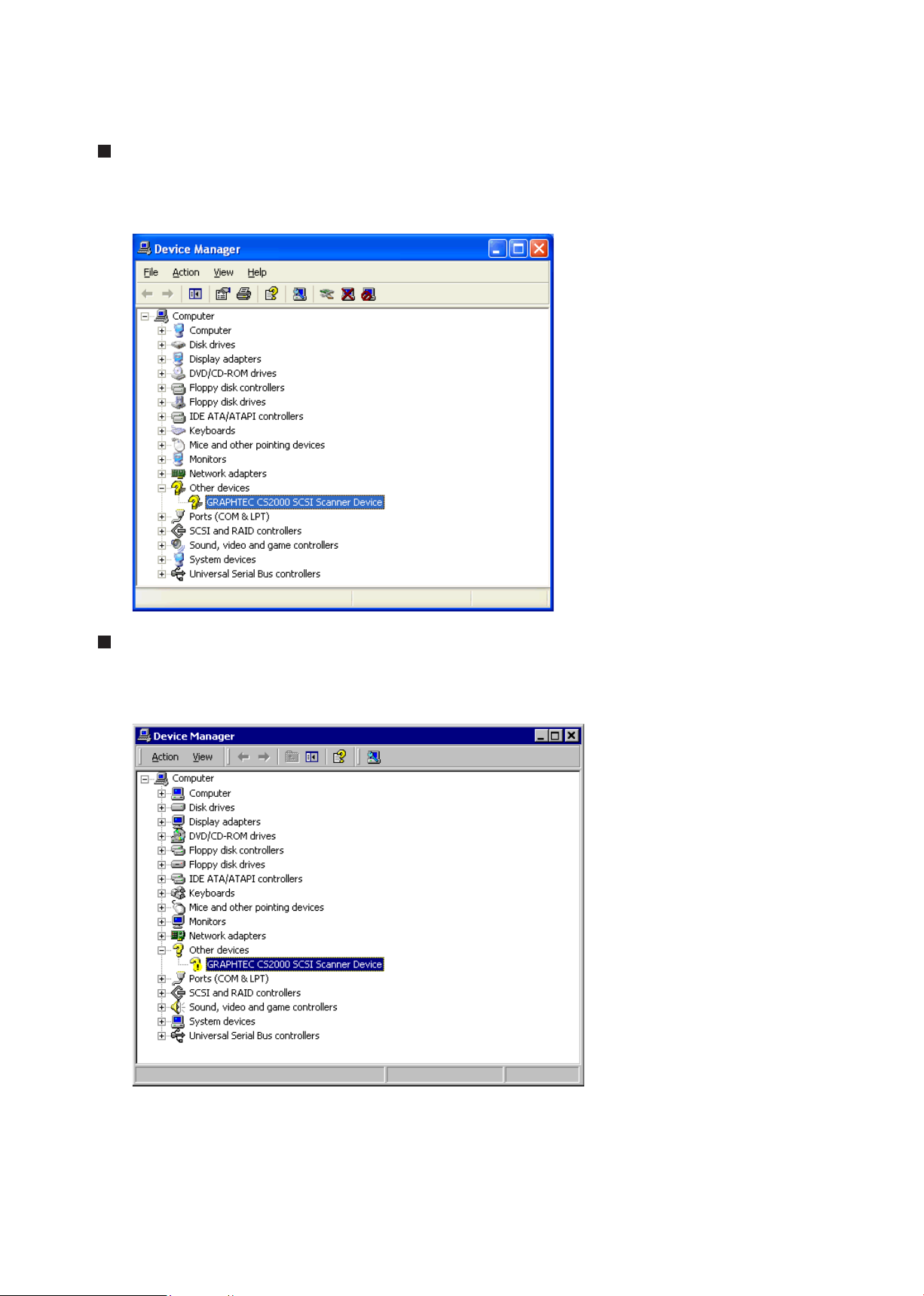
For Windows XP
Select Control Panel from the Start Menu, and then click Performance and Maintenance.
Click System. Click the Hardware tab. Click the Device Manager button to list the devices.
Check that the scanner recognized is listed under “Other devices”.
For Windows 2000
From the Control Panel folder in the My Computer directory, select the System icon. Next, click the Hardware
tab and then click the Device Manager button to display a list of the installed devices.
Check that the CS2000 scanner is acknowledged by the computer under “Other devices.”
Page 31

CS2000-UM-251-9370 4-11
4. OPERATION AND CONNECTION
4.3 Installing the Scanning Master 21+ Application
The Scanning Master 21+ “OPS112” is a software application for using a Graphtec scanner to scan image
data. The OPS112 User’s Manual is contained in the le name “OPS112-1.pdf”.
Operating Environment
Windows 95/Windows 98/Windows Me, Windows NT 4.0, or Windows 2000/XP.
Installation Procedure
(The following steps are explained using the Windows 95 windows.)
(1) Boot Windows 95.
(2) Insert the CS2000 User Guide CD-ROM containing the OPS112 program les into the computer’s
CD-ROM drive.
(3) Click the Taskbar’s Start button, then click the Run... icon.
(4) Enter the CD-ROM drive name and OPS112\DISK1\SETUP.EXE as the name of the le you wish to
open. If the disk is in drive D, for example, enter “D:\OPS112\DISK1\SETUP.EXE” in the box.
(5) Click the OK button to run the OPS112 setup program. From this point on, follow the setup program’s
instructions to install the OPS112 application.
• If the application has been properly installed, “Scanning Master 21+” will be newly listed in the Program
menu accessed from the Start button.
For more details, open the README.TXT le provided in the “Scanning Master 21+” folder.
Page 32

CS2000-UM-251-9370 4-12
4. OPERATION AND CONNECTION
4.4 Document Types Compatible with the CS2000
Because the CS2000 scans a document while feeding it, the document types that it can scan are subject to
the following restrictions.
Compatible Media Widths for Scanning
Documents with a maximum width of 1000 mm
Size ISO Size ANSI
A4 210 mm x 297 mm A 8.5 in x 11 in
A3 297 mm x 420 mm B 11 in x 17 in
A2 420 mm x 594 mm C 17 in x 22 in
A1 594 mm x 841 mm D 22 in x 34 in
A0 841 mm x 1189 mm E 34 in x 44 in
Compatible Media Lengths for Scanning
When loaded in the usual manner, a document with a maximum length of 4 meters can be scanned (due
to restrictions such as the computer’s available memory, the hard disk’s storage capacity, and so on).
Compatible Grades & Thickness for Scanning
Media Grades
The scanning precision is guaranteed for high-grade tracing paper (see “Working environment” in
APPENDIX B, “SPECIFICATIONS”).
Other compatible media types are listed below.
High-grade paper : 60 g/m
Tracing paper : 50 to 55 g/m
2
2
Mylar : 50 mm
Copy paper
Diazo photo-sensitive paper
Media Thicknesses
Observe the following points when scanning a thick medium.
• The CS2000 cannot scan a document that is thicker than 1.5 mm.
• When using the carrier sheet, ensure that the combined thickness of both the document and carrier
sheet does not exceed 1.5 mm.
• The carrier sheet alone is 0.2 mm thick.
Page 33

CS2000-UM-251-9370 4-13
4. OPERATION AND CONNECTION
Scanning table
Document
4.5 Loading a Document
For standard-size documents
Insert the document into the document-scanning table with the face to be scanned facing downward, so that
it is aligned with the center section, to ensure that it is not scanned at an angle. The two modes described
below are provided for loading the document (set from the driver software).
The rollers start rotating after a preset delay time after the document is inserted, to automatically advance
the document to the initial position for scanning.
The rollers start rotating when the FORWARD switch is pressed on the control panel after the document is
inserted, to automatically advance the document to the initial position for scanning (manual loading).
To reposition the document, press the REVERSE switch to remove it, and load it again.
If the PAPER LED does not light after the document feed operation has stopped, press the FORWARD key to ad-
vance the document again.
After the CS2000 is turned on and the driver settings have been enabled in the Scan window, it waits for approxi-
mately two seconds before beginning the specied scan operation.
Load the document in the scanner with the face to be scanned facing downward.
Do not place anything other than the document to be scanned on the scanning table, as the scanner rollers may
start rotating, which is extremely dangerous.
The document may not be fed in correctly if it is curled. The carrier sheet provided should be used for curled docu-
ments (see “4.7 Using the Carrier Sheet” for details).
Load the document in the center of the scanner, as the document may be fed in at an angle and not scanned cor-
rectly if it is signicantly off-center.
Page 34
CS2000-UM-251-9370 4-14
4. OPERATION AND CONNECTION
High
Standard
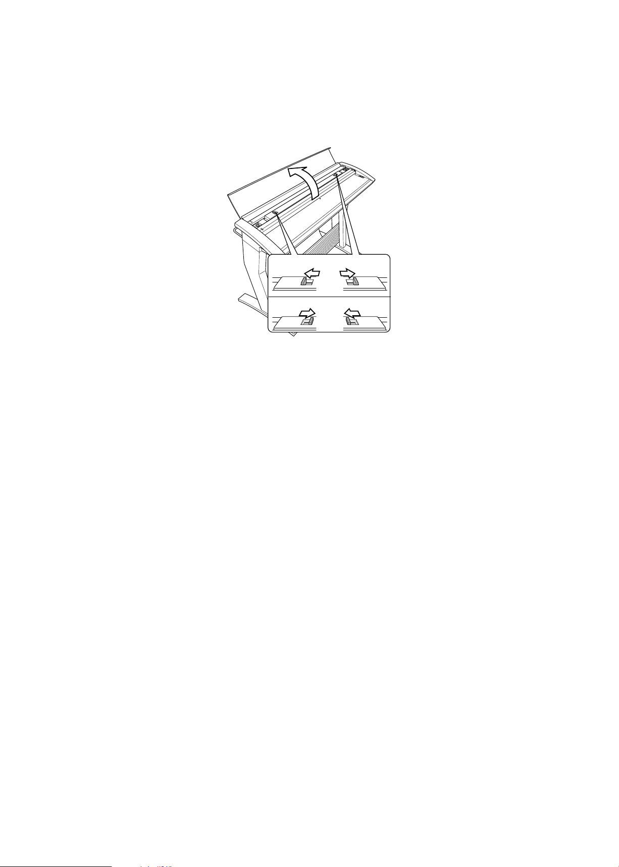
4.6 Making the Document Hold-Down Unit Force Settings
Changing the positions of the two levers at the top of the document hold-down unit enables you to switch
between two hold-down force settings.
High .............. Use this setting with:
• Plain paper with a thickness of 0.8 mm or higher
• Documents with creases or strongly curled documents where the creases or curl affect the
scanning quality
Standard ...... Use this setting with:
• Plain paper with a thickness less than 0.8 mm
• Delicate or limp documents
Page 35
CS2000-UM-251-9370 4-15
4. OPERATION AND CONNECTION
Insert in this
direction
Transparent sheet
(front surface)
Target document
(the surface to be scanned faces up)
White surface
(background surface)
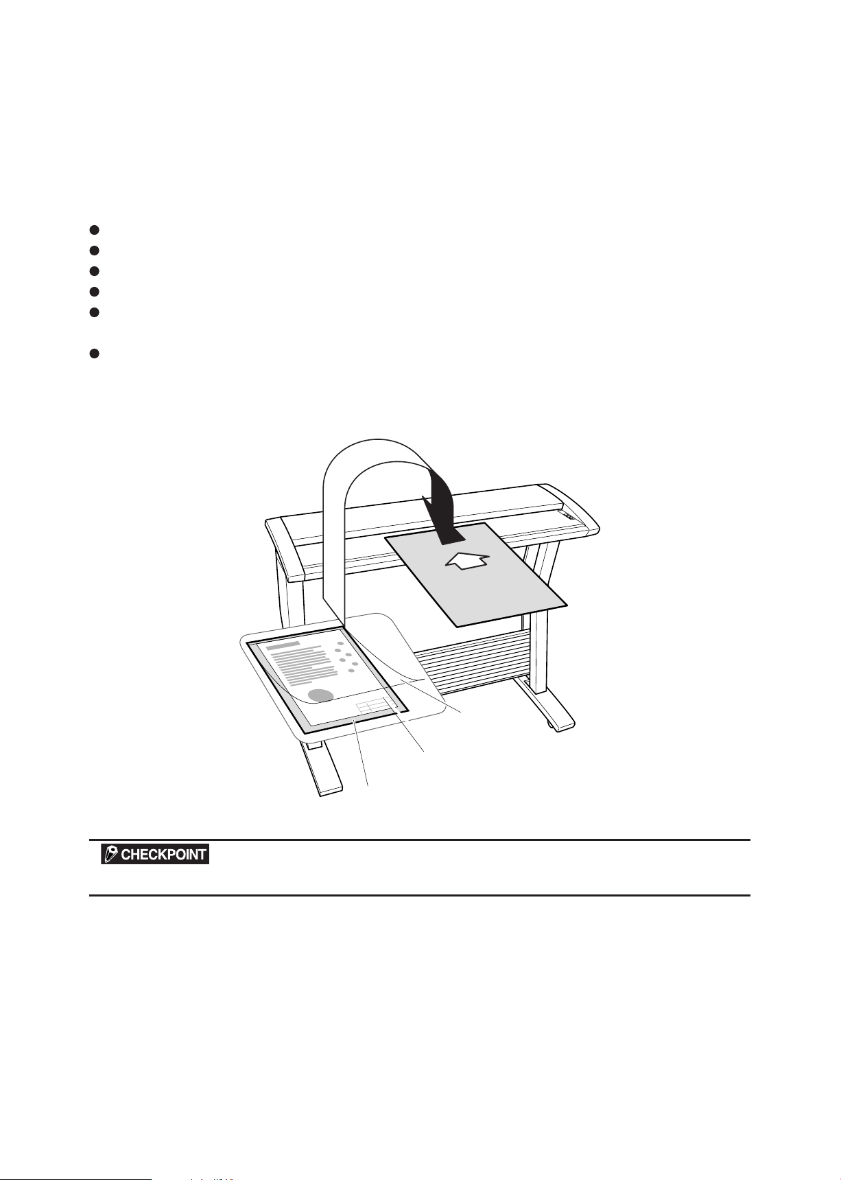
4.7 Using the Carrier Sheet
Use the carrier sheet according to the condition of the document to be scanned.
In the case of scanning the following types of media, always place the document on the carrier sheet before
loading it into the scanner.
To scan a medium that is as limp as or limper than a newspaper
To scan paper that is badly curled
To scan a document that is smaller than A4 size or a document of non-standard size
To scan a medium that tears easily
When the target document cannot be properly advanced to the initial position of scanning (because the
target document is folded, wrinkled, or otherwise hard to load in the scanner)
To scan transparent or translucent documents
As shown in the gure below, place the document in the carrier sheet with the document’s surface to be
scanned facing up (against the transparent top sheet). For scanning, load the carrier sheet into the scanner
with the document’s target surface (the transparent top sheet) facing down.
When handling the carrier sheet, be very careful not to scratch it or otherwise damage it.
Page 36

CS2000-UM-251-9370 4-16
4. OPERATION AND CONNECTION
4.8 Scanner Driver Software Compatibility with Windows 2000
Precautions for installing scanner driver software (Scanning Master, TWAIN32) on your PC to run under
Windows 2000
Running the scanner driver software under Windows 2000 requires the ASPI Manager in addition to the SCSI
board driver software (provided with Windows 2000). This software is to be supplied by Adaptec.
4.9 How to Obtain (Install) the ASPI Manager
1. What you will need
(1) Copy of the warranty accompanying the purchased SCSI board
(2) ASPI layer update software available at the Adaptec website
You can find this software or “ASPI32.EXE” among updates at http://www.adaptec.com/
2. How to obtain ASPI Manager
ASPI Manager for Windows 2000 will be available at the Adaptec website.
You can find this software at http://www.adaptec.com.
3. How to install ASPI Manager
(1) Install the SCSI card in your PC.
(2) Install programs in the oppy disk from Adaptec into Windows 2000.
To do this, double-click “Setup32.exe” in the oppy disk.
(3) Use the update software obtained in Step (2) of Section 1 to update the ASPI layer.
When you are nished, you are ready to run the scanner driver.
Page 37

CS2000-UM-251-9370 4-17
4. OPERATION AND CONNECTION
Version information
ASPI is properly installed and is fully operational.
One host adapter has been detected.
ASPI is not properly installed.
4.10 Checking the ASPI Layer
You can follow the steps given below to check whether the ASPI layer is compatible with Windows 2000.
(1) Download the ASPICHK.EXE file from the Adaptec website at http://www.adaptec.com/worldwide/suppo
rt/driverdetail.html?filekey=aspichk.exe.
(2) Start your PC and run “ASPICHK.EXE.”
Compatible with Windows 2000
Not compatible with Windows 2000
Page 38

CS2000-UM-251-9370 4-18
4. OPERATION AND CONNECTION
4.11
(1) Select “Start” → “Settings” → “Control Panel” → “Management Tools” → “Computer Management”.
(2) Select “System Tools” → “System Information” → “Software Environment.” → “Drivers”. Next, select
Checking Windows 2000 ASPI32 Status and Starting the Software
“Display” → “Detailed Settings”.
Check that “Running” appears under “Status” for “aspi32.”
Check that “Running” appears under “Status” for “aic78xx.” (AHA-2910C,AHA-2940AU)
Check that “Running” appears under “Status” for “adf6u160.” (AVA-2915LP, AVA-2930LP)
Page 39

CS2000-UM-251-9370 4-19
4. OPERATION AND CONNECTION
If “Running” does not appear (Windows 2000 ASPI32 is not running), follow the steps given
below:
(1) Right-click the My Computer icon and select “Properties”.
(2) Click the “Device Manager” from the “Hardware” tab.
(3) Select “Display non-displayed devices” from the “View” menu.
(4) Double-click “Non-Plug and Play Drivers”, then select and right-click “ASPI32.”
Then, click “Properties”.
(5) Click the “Driver” tab. Check that “Started” appears as the current status. If “Started” does not appear,
click the “Start” button.
Page 40

CS2000-UM-251-9370 4-20
4. OPERATION AND CONNECTION
(6) If “Automatic” is selected as Startup Type, click the down-arrow, select “System,” and click on the “OK”
button to change the Startup Type to “System.”
(7) Check that “System” and “Running” respectively appear under “Start Mode” and “Status” for ASPI32.
Page 41

CS2000-UM-251-9370 4-21
4. OPERATION AND CONNECTION
4.12 Changing the Transfer Rate with the AVA-2915LP (Ultra SCSI-compliant) Card
With the ADAPTEC AVA-2915LP UltraSCSI card, the transfer rate is set by default to 20 Mbps.
This may cause problems. For example, your PC may not detect the scanner when it is connected.
To avoid such problems, reduce the transfer rate to 10 Mbps.
Procedure
(1) Have the oppy disk supplied with the SCSI card ready.
Floppy disk name: Adaptec SCSI Select v2.57.4 for AVA-2915LP/2930LP.
(2) Insert the oppy disk into the oppy disk drive and turn on your PC.
(3) When “AVA-2915/30LP at Bus; 00h Device; 09h” appears, select “Congure/View Host Adapter settings”
and press the Enter key.
(4) Use the down-arrow key to select “SCSI Device Conguration.” Press the “Enter” key.
Page 42

CS2000-UM-251-9370 4-22
4. OPERATION AND CONNECTION
(5) Change the “Maximum Sync Transfer Rate” for the corresponding SCSI ID.
If (for example) your scanner’s SCSI ID is 2, select “Sync Transfer Rate (MB/Sec)” for the SCSI Device
ID #2 and press the “Enter” key. Then use the down-arrow key to select “10.0” and press the “Enter” key.
(6) Press the “Esc” key twice. When “Save Changes Made?” appears, select “Yes” and press the “Enter”
key.
(7) Press the “Esc” key. When “Exit Utility?” appears, select “Yes” and press the “Enter” key.
(8) When “Please press any key to reboot” appears, remove the oppy disk and press any key. At this time,
your PC will restart.
Checkpoint: If you have a FastSCSI card such as AHA-2910C or AHA-1520B, you do not need to change the trans-
fer rate.
Page 43

CS2000-UM-251-9370 4-23
4. OPERATION AND CONNECTION
4.14 Factory Settings
1 2 3 4
ON
DIP Switch's bits
Te
rminator
Enable
Disable
Usually OFF
OFF
ON
4 3 2 1
DIP Switch
All of 1 to 4 are OFF (Terminator is enabled).
ID Number
Set to No. 2
Page 44

5. DAILY MAINTENANCE
Top cover
5. DAILY MAINTENANCE
5.1 Removing and Mounting the Document Hold-Down Unit
To clean the scanner, you must rst remove the document hold-down unit. It is also necessary to remove the
document hold-down unit to remove a jammed document.
Removing the Document Hold- Down Unit
(1) Turn off the scanner.
(2) Open the top cover, holding it in the center.
(3) From inside the scanner, lift up the handle-rings provided at each side of the document hold-down unit in
order to lift the document hold-down unit up and off.
CS2000-UM-251-9370 5-1
Page 45

CS2000-UM-251-9370 5-2
5. DAILY MAINTENANCE
Mounting the Document Hold-Down Unit
(1) While holding the document hold-down unit by the handle-ring at each side, lower the document
hold-down unit straight down into the scanner.
(2) Push down the handle- rings on each side of the document hold-down unit.
(3) Close the top cover, holding it in the center.
The document hold- down unit has a symmetrical shape, so it is physically possible to mount it with its right and left
sides reversed. Because the scanner’s precision has been adjusted before shipment from the factory, however, its
reading precision will decrease extremely if you mount the document hold - down unit in reverse.
Before mounting the document hold-down unit, be sure to check its proper orientation as indicated on the seals at-
tached to the scanner and the document hold-down unit.
Fully insert the document hold-down unit to the bottom end. If the document holddown unit is not pressed down,
this will result in reduced image quality and paper jamming.
Page 46
CS2000-UM-251-9370 5-3
5. DAILY MAINTENANCE
Underside
5.2 Cleaning the Document Hold-Down Unit
(1) Turn off the scanner.
(2) Remove the document hold-down unit as described in Section 5.1 “Removing and Mounting the
Document Hold-Down Unit”.
(3) Lay the document hold-down unit on a stable surface, with the underside facing the side as shown.
(4) Wipe clean the underside of the document hold-down unit (see below) using a soft cloth that has been
soaked in water or diluted neutral detergent and thoroughly wrung out.
Scanning may be affected if the underside of the document hold-down unit becomes scratched or dirty. It must be
cleaned when necessary.
(5) Wipe the document hold-down unit once again using a soft, dry cloth (remove all moisture).
(6) Reattach the document hold-down unit as described in Section 8.2 “Document Hold-Down Unit.”
Page 47

CS2000-UM-251-9370 5-4
5. DAILY MAINTENANCE
Transparent contact plates
5.3 Cleaning the Image Sensors
The scanner’s image quality drops when the transparent contact plates over the image sensors become dirty,
so clean the image sensors whenever necessary.
Procedure
(1) Turn off the scanner.
(2) Remove the document hold-down unit as described in Section 8.2 “Document Hold-Down Unit.”
(3) As shown below, wipe off any soiled areas on the transparent contact plates using a soft cloth that has
been moistened with water or a neutral detergent (diluted with water) and rmly wrung out.
(4) Completely remove any moisture on the transparent contact plates by wiping them off again using a soft,
dry cloth.
(5) Mount the document hold-down unit as described in Section 8.2 “Document Hold-Down Unit.”
Do not use a commercial cleaner for ofce equipment, a glass cleaner, or chemical solvents such as solutions con-
taining alcohol.
Page 48

CS2000-UM-251-9370 5-5
5. DAILY MAINTENANCE
Although the glass scanning table is not a maintenance part that requires periodic replacement, it is a consumable
part because its surface may receive slight scratches due to minute particles of dust and other foreign matter. If
document scanning produces unsatisfactory results (unexpected white or black streaks in the data) due to scratch-
es on the glass table or other reasons, please perform the calibration procedure (see Section 10.4, “1. Calibration”).
If the scanning results do not improve after calibration, the glass table will need to be replaced.
Page 49

CS2000-UM-251-9370 5-6
5. DAILY MAINTENANCE
Paper sensors
5.4 Cleaning the Paper Sensors
Accumulated dust on the paper sensors may prevent the document from being detected. The sensors must be
cleaned when necessary.
(1) Turn off the scanner.
(2) Open the top cover, holding it in the center.
(3) Wipe the two paper sensors using a cotton swab.
(4) Close the top cover, holding it in the center.
Page 50

CS2000-UM-251-9370 5-7
5. DAILY MAINTENANCE
5.5 Removing a Jammed Document
If a document becomes jammed in the scanner during scanning or another operation, immediately turn off
the scanner, remove the document hold-down unit, and then remove the jammed document.
Procedure
(1) Turn off the scanner.
(2) Remove the document hold-down unit as described in Section 8.2 “Document Hold-Down Unit.”
(3) If the document is jammed at the front, remove the document from the inside or by pulling it forward.
Page 51

5. DAILY MAINTENANCE
(4) If the document is jammed at the rear, remove the document from the inside by pulling it toward the rear.
(5) Reattach the document hold-down unit as described in Section 8.2 “Document Hold-Down Unit,” and
close the top cover.
CS2000-UM-251-9370 5-8
Page 52

6. RECOMMENDED PARTS LIST
6. RECOMMENDED PARTS LIST
No Parts No Description Part name Q'ty Remarks
1 378019021 Drive Belt Belt 60S2M380 1 Same as CS1000
2 500050305 ID Switch ID Switch 1 Same as CS1000
3 500050731 Memory 128MB D2V4A8D- CL2 1 Same as CS1000
4 500050736 24V Switching Power Supply LDA75F-24-H 1 Same as CS1000
5 500050745 Motor KT60LM06 -551 1 Same as CS1000
6 694450002 Cable CIS to main board L CS2000C-1 1 Same as CS1000
7 694450033 Cable CIS to main board S CS2000C-4 1 Same as CS1000
8 500050803 3.3V Switching Power Supply LDA15F-3 -3.3 1 Same as CS1000
9 500050804 5V Switching Power Supply LDA15F-5 1 Same as CS1000
10 694450051 Cooling Fan CS2000C- 6 1
11 502112009 Power Switch Sw,AJ7201B 1 Same as CS1000
12 502210002 Paper Sensor PS-R50L-A 1 Same as CS1000
13 640310450 Document Support Wires IS31 Document Support Wires 3 Same as CS1000
14 641000663 CS Retaining Plate CS Retaining Plate 1
15 641000240 Drive Roller CS Drive Roller 2 Same as CS1000
16 641200100 Front Guide 20 CS20 Front Guide 1
17 641200120 Left Side Cover L20 CS Side Cover Left 20 1
18 641200130 Right Side Cover R20 CS Side Cover Right 20 1
19 641200290 Top Cover CS Top Cover 20 1
20 641000840 Control Panel CS10 Control Panel 1 Same as CS1000
21 694440011 Rear Sensor Cable CS1000C-1 1 Same as CS1000
22 694440021 Front Sensor Cable CS1000C -2 1 Same as CS1000
23 694440032 Sensor Unit CS1000C-3 1 Same as CS1000
24 774014500 Main Board Main Board 1
25 774014501 CIS Control Board A CIS Control Board A 1
26 774014502 CIS Control Board B CIS Control Board B 1
27 774014503 CIS Control Board C CIS Control Board C 1
28 774014900 (Maintenance) Image Sensor Unit 1
29 774012810 (Maintenance) Pinch Roller Unit 2 Same as CS1000
30 774012820 (Maintenance) Glass Base Unit 1 Same as CS1000
31 794021091 Control Panel Board IS21 Control Panel Board 1 Same as CS1000
32 641200200 Shading Assy-RMD
33 774014901 (Maintenance)
Calibration Sheet, Color Correction Sheet
Document Hold Down Unit CS2000
1
1
CS2000-UM-251-9370 6-1
Page 53

7. LIST OF JIGS AND TOOLS
7. LIST OF JIGS AND TOOLS
7.1 Jigs
Jigs Adjustments Remarks
Spacer (BSB-335) •Attaching main board to bottom plate,
large
CS2000.X •Downloading system program Firmware
OPS112 •Downloading system program
•Shading (white correction)
•Adjusting feed distance
•Aligning sensor images
•Adjusting offset
•Shading (undesired color line removal)
•Shading (undesired gray line removal)
•Used to check resolution
•Color correction
Calibration sheet •Shading (white correction)
•Replacing main board
Color correction sheet •Color correction Standard accessory
CS1000 adjustment test chart
(for CS2000 also)
Undesired color line removal
check paper
(one gray and one beige/white color paper)
Fax test chart No. 3
(4 sheets)
MTF adjustment test chart •Resolution checking 6 -line-pair resolution pattern
•Adjusting feed distance
•Adjusting offset
•Aligning sensor images
•Shading (undesired color line removal) For checking undesired color or white
•Shading (undesired gray line removal) For checking undesired gray or black
Hexagonal, 35 mm in length
Software supplied with the scanner
(Scanning Master 21+)
Standard accessory
1050 mm x 200 mm
Record measured values betweena and
c, b and d, a and b, c and d, a and d, and
b and c.
lines
lines
7.2 Tools
Tools Uage Remarks
Screwdriver
Allen wrench
Needle-nose pliers
Colex gauge Adjusting belt tension 200 g/4 mm displacement
Multimeter Checking voltage level
Disassembly, reassembly,and other
operations
Large, medium, and small flatblade
screwdrivers and Phillips screwdrivers
7.3 Other
Item Usage Remarks
Water-diluted neutral detergent or
absolute ethanol wiper (cloth)
PC
SCSI card
SCSI cable
Cleaning
Used to determine whether the problem
is caused by the scanner or any other
equipment.
CS2000-UM-251-9370 7-1
Page 54

8. DISASSEMBLING AND ADJUSTING MECHANICAL PARTS
Mapped scre
ws
Mapped screws
Height adjustment scre
ws
Height adjustment screws
Inside bottom plate L
Inside bottom plate L
8. DISASSEMBLING AND ADJUSTING MECHANICAL PARTS
8.1 Considerations before starting disassembly
To prevent damage to image sensors, remove the document hold-down unit before disassembling any
mechanical parts.
Removing screws and any parts other than those shown in this chapter may adversely affect scanner
performance, including degraded scanning accuracy.
In particular, never attempt to remove or turn the red shielded screws and height adjustment screws.
The directions "left" and "right" given in this chapter assume that the scanner unit is viewed from the
front.
CS2000-UM-251-9370 8-1
Page 55

CS2000-UM-251-9370 8-2
8. DISASSEMBLING AND ADJUSTING MECHANICAL PARTS
Top cover
8.2 Document Hold-down Unit
Detaching the document hold-down unit
(1) Turn off the scanner.
(2) Open the top cover, grasping it at the center.
(3) Set the handle-ring at each end of the document hold-down unit upright, hold these handle-ring with your
hands, and raise the unit from the scanner unit.
Page 56

CS2000-UM-251-9370 8-3
8. DISASSEMBLING AND ADJUSTING MECHANICAL PARTS
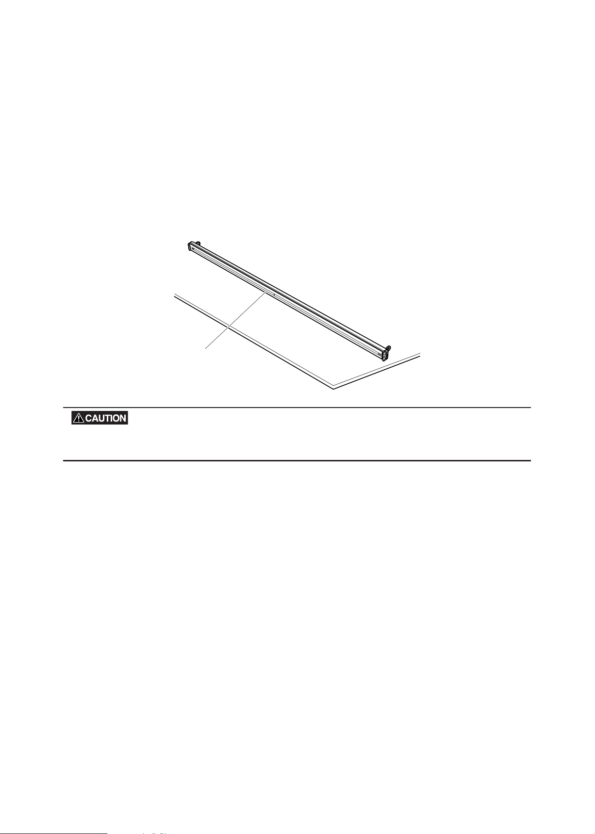
CS retaining plate
Align the marks
(4) Once the document hold-down unit has been removed, set the CS retaining plate (white section) on its
side on a stable surface.
Scanning may be affected if the underside of the document hold-down unit becomes scratched or dirty.
Reattaching the document hold-down unit
(1) Check the orientation stickers on the scanner unit and the document hold-down unit. Hold the
handle-ring on each side of the unit and lower the unit to t it into the scanner unit.
(2) Fold the handle-ring on each side of the unit back into place.
(3) Close the top cover, grasping it at the center.
The clearance between the document hold-down unit and the separator plates has been factory-adjusted for accu-
racy. Attaching the unit in the wrong way will signicantly affect scanning accuracy. Be sure to check the orientation
stickers (marked with ) on the scanner unit and the document hold- down unit before attaching the unit. (See the
gure above) Insert the document hold - down unit all the way to the bottom. If the unit is not pressed down, image
quality will be degraded and paper jams more likely to occur.
Page 57

CS2000-UM-251-9370 8-4
8. DISASSEMBLING AND ADJUSTING MECHANICAL PARTS
Detaching the document
hold-down unit
Detaching the
CS retaining plate
8.2
p.8-2
This Section
M3L6 flat head screw
CS Retaining Plate (white section)
Document hold-down unit
8.3 CS Retaining Plate
Disassembly procedure
Detaching the CS Retaining Plate
(1) Check the orientation (left- and right-hand sides) of the CS retaining plate (white section).
(2) With the CS retaining plate facing up, remove the silver M3L6 at head screw.
(3) Pull out each of the right- and left-hand undersides one at a time, then detach the CS retaining plate.
When detaching the undersides, note that the spring inside may y out. Take appropriate measures to avoid losing
the spring.
Reattaching the CS Retaining Plate
(1) Reattach the CS retaining plate with the same direction as before its removal. (You do not need to check
for orientation when replacing with a new CS retaining plate.)
The clearance between the document hold-down unit and the separator plates has been factory-adjusted for ac-
curacy. Attaching the unit's underside in the wrong direction can signicantly affect scanning accuracy. Be sure to
reattach it with the same direction as before its removal. You need to adjust the clearance between the document
hold-down unit and the separator plates when you are going to install new document hold-down unit (see subsec-
tion 8.13 "Reattaching the separator plates").
Page 58

CS2000-UM-251-9370 8-5
8. DISASSEMBLING AND ADJUSTING MECHANICAL PARTS
Detaching the document
hold-down unit
Detaching the side covers
8.2
p.8-2
This Section
M4L6 binding head screws
1 mm max.
1 mm max.
Top cover
Side cover
8.4 Side Covers
Disassembly procedure
Detaching the side covers
(1) Remove the four black M4L6 binding head screws on each side of the scanner unit. (Both sides)
(2) Detach the side covers.
Reattaching the side covers
(1) Reattach the side covers in the reverse order in which they were detached.
(2) Make sure the clearance between the top cover and each of the side covers is 1 mm or less.
Page 59

CS2000-UM-251-9370 8-6
8. DISASSEMBLING AND ADJUSTING MECHANICAL PARTS
Detaching the document
hold-down unit
Detaching the top cover
8.2
p.8-2
This Section
Detaching the side covers
8.4
p.8-5
M3L6TP screws
Top cover
Rubber coverTop cover stay
E-r
ing
E-ring
M4L8 binding
head scre
ws
M4L8 binding
head screws
8.5 Top Cover
Disassembly procedure
Detaching the top cover
(1) Remove the four black M3L6TP screws in the back of the top cover and detach the upper section of the
cover.
(2) Detach the rubber cover from the M4L8 binding head screw.
(3) Detach the E-ring from the right-hand surface and two silver M4L8 binding head screws from the
left-hand surface.
(4) Pull out the top cover stay.
Reattaching the top cover
(1) Reattach the top cover in the reverse order in which it was detached.
(2) Make sure the clearance between the top cover and each of the side covers is 1 mm or less. (See the
previous page.)
Page 60
CS2000-UM-251-9370 8-7
8. DISASSEMBLING AND ADJUSTING MECHANICAL PARTS
Detaching the document
hold-down unit
Detaching the front cover
8.2
p.8-2
This Section
Detaching the side covers
8.4
p.8-5
M4L8 binding head screws
Front cover
M4L8 binding head screws
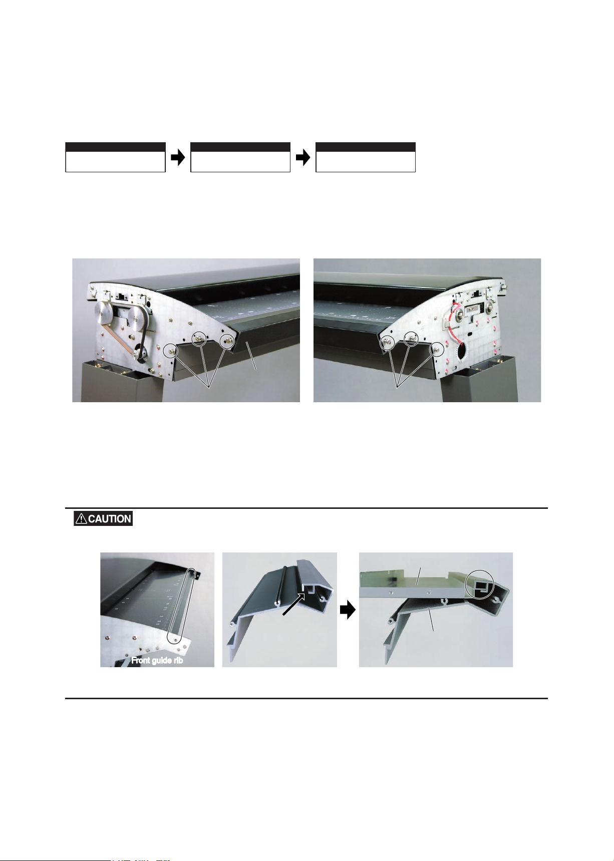
F
ront guide r
ib
Front guide rib Front cover
Fit the rib here.
Front cover
Front guide
8.6 Front Cover
Disassembly procedure
Detaching the front cover
(1) Remove the three silver M4L6 binding head screws holding the front cover from each side.
(2) Pull the front cover toward you to detach it.
Reattaching the front cover
(1) Reattach the front cover in the reverse order in which it was detached.
When reattaching the front cover, be sure to t the front guide rib into a section of the front cover, as shown below.
Page 61
CS2000-UM-251-9370 8-8
8. DISASSEMBLING AND ADJUSTING MECHANICAL PARTS
Detaching the document
hold-down unit
8.2
p.8-2
This Section
Detaching the rear cover
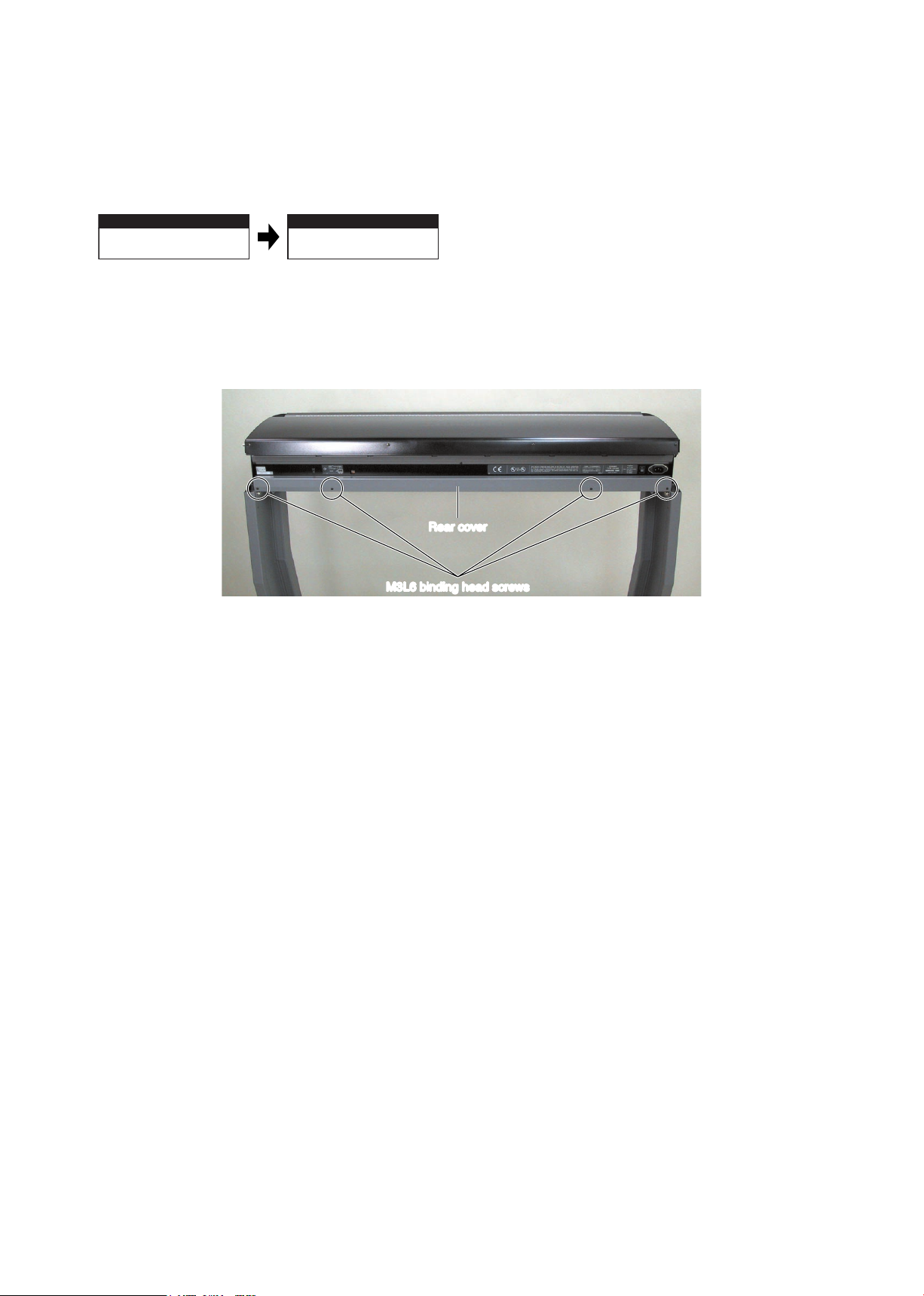
M3L6 binding head scre
ws
M3L6 binding head screws
Rear co
v
er
Rear cover
8.7 Rear Cover
Disassembly procedure
Detaching the rear cover
(1) Remove the four black M3L6 binding head screws in the back of the scanner unit.
(2) Detach the rear cover.
Reattaching the rear cover
(1) Reattach the rear cover in the reverse order in which it was detached.
Page 62

CS2000-UM-251-9370 8-9
8. DISASSEMBLING AND ADJUSTING MECHANICAL PARTS
Detaching the document
hold-down unit
Detaching the large and
small bottom plates
8.2
p.8-2
This Section
M3L6TP screws
Front
Front
Large bottom plate
M3L6TP screws M3L6TP screws
Front
Front
Front
Front
S
mall
b
ottom plate (left side)
Small bottom plate (left side) S
mall
b
ottom plate (right side)
Small bottom plate (right side)
8.8 Large and Small Bottom Plates
Disassembly procedure
Detaching the large and small bottom plates
(1) Remove the three silver M3L6TP screws while supporting the large bottom plate with one hand.
(2) Remove the four silver M3L6TP screws while supporting the small bottom plates (left and right sides)
with one hand.
Support the bottom plates to keep them from dropping when the screws are removed.
Reattaching the bottom plates
(1) Reattach the bottom plates in the reverse order in which they were detached.
(2) Make sure the ventilating openings face forward when reattaching the bottom plates.
The attachment direction of the small bottom plates is specied by a UL standard. Special care must be taken to
attach the panel correctly.
Page 63

CS2000-UM-251-9370 8-10
8. DISASSEMBLING AND ADJUSTING MECHANICAL PARTS
Detaching the document
hold-down unit
Detaching the large
bottom plate
Detaching the main board
8.2
p.8-2
This Section
8.8
p.8-9
BSB-335
M3L6 binding head scre
ws
M3L6 binding head screws
Main board
8.9 Main Board
Disassembly procedure
When securing the main board to the jig (BSB-335)
Detaching the main board
(1) Attach the jig (BSB-335) to the inside of the large bottom plate.
(2) Remove the six silver M3L6 binding head screws while supporting the main board with one hand.
To prevent the main board from falling and damaging its connectors and wiring when the screws are removed, be
sure to support the board.
Page 64

CS2000-UM-251-9370 8-11
8. DISASSEMBLING AND ADJUSTING MECHANICAL PARTS
M3L6 binding head scre
ws
M3L6 binding head screws
(3) To secure the board to the jig (BSB-335), use the two silver M3L6 binding head screws that were used to
hold the main board.
When attaching the main board to the jig (BSB-335), remove tie wraps and other restraints as necessary to prevent
the wiring and connectors from becoming strained.
Reattaching the main board
(1) Reattach the main board in the reverse order in which it was detached.
When detaching the main board completely (not for securing it to the jig)
Detaching the main board
(1) Remove all connectors and the six silver M3L6 binding head screws while supporting the board. (See the
previous page.)
To prevent the main board from falling and damaging its connectors and wiring when the screws are removed, be
sure to support the board.
(2) Place the main board on a safe and stable surface.
Reattaching the main board
(1) Reattach the board in the reverse order in which it was detached.
Page 65
CS2000-UM-251-9370 8-12
8. DISASSEMBLING AND ADJUSTING MECHANICAL PARTS
Detaching the document
hold-down unit
Detaching the large
bottom plate
Detaching the power
boards
8.2
p.8-2
This Section
8.8
p.8-9
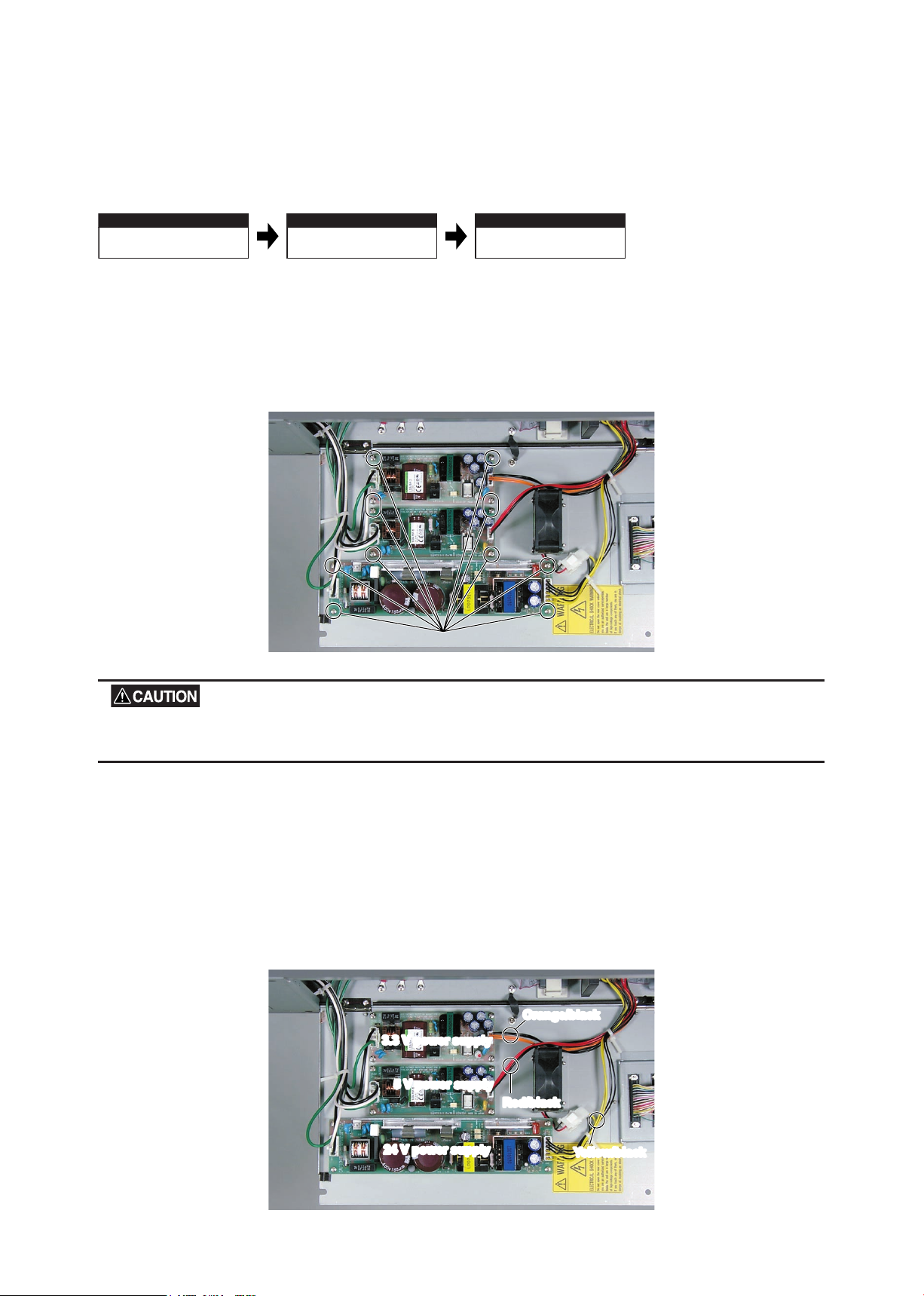
M3L6 binding head screws
3.3 V power supply
3.3 V power supply
5 V power supply
5 V power supply
24 V power supply
24 V power supply
Orange/black
Orange/black
Red/black
Red/black
Y
ellow/black
Yellow/black
8.10 Power Boards
Disassembly procedure
Detaching the power boards
(1) Remove all connectors and the four silver M3L6 binding head screws from each of the power boards,
while supporting the board with one hand.
To prevent the power boards from falling and becoming damaged when the screws are removed, be sure to support
each of the boards.
(2) Place each of the boards on a safe and stable surface.
Reattaching the power boards
(1) Reattach the boards in the reverse order in which they were detached.
(2) Be sure to attach each board at the appropriate location and to the appropricte connectors. When
attaching the connectors, check the cable colors as shown below.
Page 66

CS2000-UM-251-9370 8-13
8. DISASSEMBLING AND ADJUSTING MECHANICAL PARTS
Detaching the document
hold-down unit
Detaching the large and
small bottom plates
Detaching the CIS boards
8.2
p.8-2
This Section
8.8
p.8-9
Detaching the main board completely
(not for securing it to the jig)
8.9
p.8-11
CIS board C
CIS board B
CIS board A
M3L6 binding head screwsM3L6 binding head screws
CIS board A
M3L6 binding head screwsM3L6 binding head screws
CIS board B
M3L6 binding head screwsM3L6 binding head screws
CIS board C
8.11 CIS (Charge Coupled Device Imaging Semsor) Boards A, B, and C
Disassembly procedure
Detaching the CIS boards
(1) Remove all connectors and the four silver M3L6 binding head screws from each of the CIS boards while
supporting the board with one hand.
To prevent the CIS boards from falling and becoming damaged when the screws are removed, be sure to support
each of the boards.
(2) Place the CIS boards on a safe and stable surface.
Reattaching the CIS boards
(1) Reattach the CIS boards in the reverse order in which they were detached.
Page 67

CS2000-UM-251-9370 8-14
8. DISASSEMBLING AND ADJUSTING MECHANICAL PARTS
Detaching the document
hold-down unit
Detaching the large
bottom plate
Detaching the cooling fan
8.2
p.8-2
This Section
8.8
p.8-9
M3L6
binding head scre
ws
M3L6
binding head screws
Cooling F
an
Cooling Fan
Bottom plate Large
Bottom plate Large
8.12 Cooling Fan
Disassembly procedure
Detaching the cooling fan
(1) Remove all connectors and the two silver M3L6 binding head screws secured to the large bottom plate.
Hold the cooling fan to keep it from falling and damaging the connectors and wiring when the screws are removed.
Page 68

CS2000-UM-251-9370 8-15
8. DISASSEMBLING AND ADJUSTING MECHANICAL PARTS
Detaching the document
hold-down unit
Detaching the side co
vers
Detaching the separator
plates
8.2
p.8-2
This Section
8.4
p.8-5
M3L6 binding head screwsM3L6 binding head screws
M3L6
binding head screws
M3L6
binding head screws
M3L6 binding head screwM3L6 binding head screw
M3L6 binding head screwM3L6 binding head screw
Separator platesSeparator plates
M3L6
binding head screws
M3L6
binding head screws
M2L8
binding head
scre
ws
M2L8
binding head
screws
Co
v
er open
sensor
Cover open
sensor
Rear of the separ
ator
plate at the front
Rear of the separator
plate at the front
8.13 Separator Plates
Disassembly procedure
Detaching the separator plates
(1) Remove the ten black M3L6 binding head screws and three silver binding head screws.
(2) Detach the cover open sensor from the separator plate at the front by removing the two black M2L8
binding head screws.
(3) Detach the separator plates.
Page 69

CS2000-UM-251-9370 8-16
8. DISASSEMBLING AND ADJUSTING MECHANICAL PARTS
Separator plates
Inser
t a b
usiness card.
Insert a business card.
Document
hold-down unit
Reattaching the separator plates
(1) Reattach the separator plates in the reverse order in which they were detached.
(2) Insert a business card or something similar between the separator plates and the document hold-down
unit to maintain appropriate clearance between them. This will make it easier to detach and reattach the
document hold-down unit.
Page 70
CS2000-UM-251-9370 8-17
8. DISASSEMBLING AND ADJUSTING MECHANICAL PARTS
Detaching the document
hold-down unit
Detaching the side co
vers
Detaching the pinch roller
units
8.2
p.8-2
This Section
8.4
p.8-5
Detaching the separator
plates
8.13
p.8-15
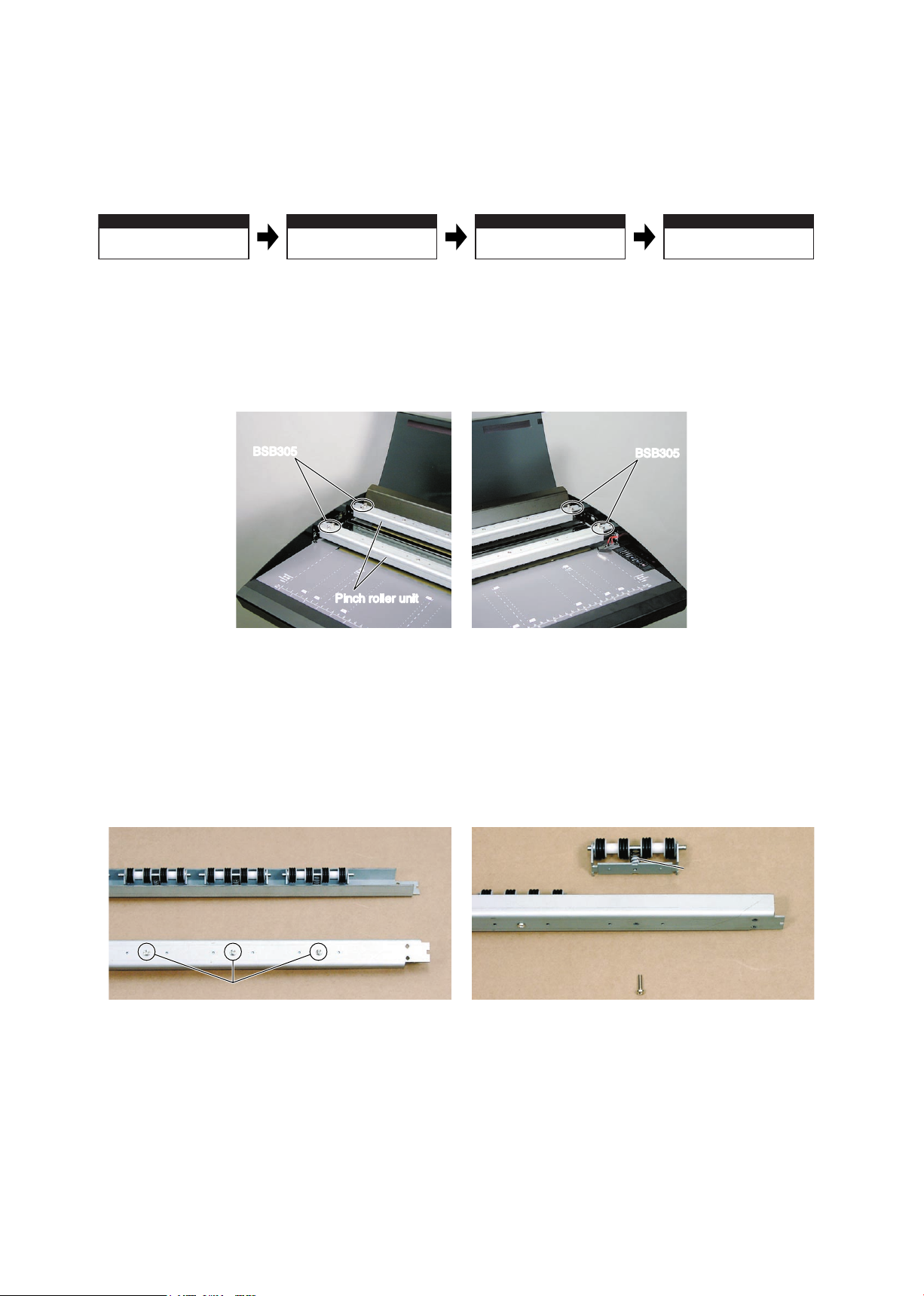
BSB305
BSB305
Pinch roller unit
Pinch roller unit
BSB305
BSB305
Rear surface of the pinch roller unit
Pinch roller as
disassembled
Front surface of the pinch roller unit
M3L14 binding head screws
This spring may
fly out.
8.14 Pinch Roller Units
Disassembly procedure
Detaching the pinch roller units
(1) Remove the two spacers (BSB305) from each side of the pinch roller units.
(You can detach the pinch roller units without removing the spacers (BSB305) in the center of the units.)
(2) Detach the pinch roller units.
Disassembling the pinch roller units
(1) Remove the three silver M3L14 binding head screws to disassemble each pinch roller unit.
Take care to keep the spring inside from ying out and becoming lost.
Page 71

CS2000-UM-251-9370 8-18
8. DISASSEMBLING AND ADJUSTING MECHANICAL PARTS
Large notches must
be on the right-hand
side and face forward.
Pinch roller
units
Pinch roller
units
Notches
A
Notches A
Notches B
Notches B
Front
OK
NG
Align notch A with notch B here.
Align
Gap
Reattaching the pinch roller units
(1) Reattach the pinch roller units in the reverse order in which they were detached.
(2) Make sure the large notch of each unit is at the right-hand side and faces forward.
(3) Align notch A of each pinch roller unit with the front section of notch B of the scanner unit when
reattaching the unit.
The paper feed and scanning accuracy may be affected if the notches are not aligned. Step (3) in “Reattaching the
pinch roller units” above must be followed.
Page 72

CS2000-UM-251-9370 8-19
8. DISASSEMBLING AND ADJUSTING MECHANICAL PARTS
Detaching the document
hold-down unit
8.2
p.8-2
Detaching the side covers
Detaching the front cover
Detaching the large
bottom plate
Detaching the front guide
This Section
Detaching the separator
plate (the front plate only)
Detaching the main board
(not for securing it to the jig)
8.4
p.8-5
8.6
p.8-7
8.8
p.8-9
8.13
p.8-15
8.9
p.8-10
M3L6 binding head screws
M3L6
binding head scre
ws
M3L6
binding head screws
M3L6 binding head scre
ws
M3L6 binding head screws
Inside bottom plate L
Inside bottom plate L
Front guide
8.15 Front Guide
Disassembly procedure
Detaching the front guide
(1) Remove the two black M3L6 binding head screws and four silver M3L6 binding head screws.
(2) Pull out the front guide.
Reattaching the front guide
(1) Make the necessary adjustments to make sure that the guide does not touch the drive roller and that no
gaps are wide enough for a document to slip into them. When you nish, tighten the M3L6 binding head
screws on the left-hand side.
(2) Tighten other screws to reattach the front guide in the reverse order in which it was detached.
Page 73

CS2000-UM-251-9370 8-20
8. DISASSEMBLING AND ADJUSTING MECHANICAL PARTS
Detaching the document
hold-down unit
Detaching the side co
vers Detaching the rear guide
8.2
p.8-2
This Section
8.4
p.8-5
Detaching the top cover
8.5
p.8-6
Loosen these M3L6 binder screws with washers
Remove these M3L6 binding head screws
Rear guide
M3L6 binding head screw
Washer
Scanner unit base
Rear guide
8.16 Rear Guide
Disassembly procedure
Detaching the rear guide
(1) Loosen the three black M3L6 binding head screws in the back of the scanner unit and remove the two
black M3L6 binding head screws on top of the scanner unit.
(2) Slide the rear guide upward to detach it.
Reattaching the rear guide
(1) Reattach the rear guide in the reverse order in which it was detached.
(2) Make the necessary adjustments to make sure that the guide does not touch the drive roller and that no
gaps are wide enough for a document to slip into them.
When attaching the rear guide, insert a washer between the rear guide and the scanner unit base.
Page 74

CS2000-UM-251-9370 8-21
8. DISASSEMBLING AND ADJUSTING MECHANICAL PARTS
Detaching the document
hold-down unit
Detaching the side co
vers
Detaching the control panel
8.2
p.8-2
This Section
8.4
p.8-5
Detaching the front cover
8.6
p.8-7
M3L6
binding head scre
ws
M3L6
binding head screws
ConnectorConnector
Control panelControl panel
8.17 Control Panel
Disassembly procedure
Detaching the control panel
(1) Remove the two silver M3L6 binding head screws.
(2) Detach the connector from the control panel.
Reattaching the control panel
(1) Reattach the control panel by reversing the sequence of steps in which it was detached.
Page 75

CS2000-UM-251-9370 8-22
8. DISASSEMBLING AND ADJUSTING MECHANICAL PARTS
Detaching the document
hold-down unit
8.2
p.8-2
Detaching the side cover
(the right-hand side cover only)
Detaching the large and small bottom
plates (the small right-hand plate only)
Detaching the separator plates
(the front plate only)
Detaching the cover open
sensor
8.4
p.8-5
8.8
p.8-9
8.13
p.8-15
This Section
M2L8
binding head
scre
ws
M2L8
binding head
screws
Co
v
er
open sensor
Cover
open sensor
Rear surf
ace of the
front separ
ator plate
Rear surface of the
front separator plate
Co
v
er open sensor
connector (red cab
le)
Cover open sensor
connector (red cable)
Main board
8.18 Cover Open Sensor
Disassembly procedure
Detaching the cover open sensor
(1) Remove the two black M2L8 binding head screws from the rear surface of the front separator plate.
(2) Detach the main board connectors from the cables.
(3) Disconnect the cables and detach the cover open sensor.
Reattaching the cover open sensor
(1) Reattach the cover open sensor by reversing the sequence of steps in which it was detached.
For optimal sensitivity, attach the sensor as far up as possible.
Page 76

CS2000-UM-251-9370 8-23
8. DISASSEMBLING AND ADJUSTING MECHANICAL PARTS
Detaching the document
hold-down unit
Detaching the side co
vers
Detaching the front paper
detection sensor
8.2
p.8-2
This Section
8.4
p.8-5
Detaching the front cover
8.6
p.8-7
M3L10
binding head screw
Connector
P
aper detection sensor
Paper detection sensor
Detaching the document
hold-down unit
8.2
p.8-2
Detaching the side covers
Detaching the top cover
Detaching the separator
plates (the rear plate only)
Detaching the rear paper
detection sensor
This Section
Detaching the rear guide
Detaching the pinch roller
units (the rear unit only)
8.4
p.8-5
8.5
p.8-6
8.13
p.8-15
8.16
p.8-19
8.14
p.8-16
8.19 Front and Rear Paper Detection Sensors
Disassembly procedure (front sensor)
Detaching the front paper detection sensor
(1) Remove the silver M3L10 binding head screw below the front guide.
(2) Detach the connector from the paper detection sensor.
Reattaching the front paper detection sensor
(1) Reattach the paper detection sensor by reversing the sequence of steps in which it was detached.
Disassembly procedure (rear sensor)
Page 77

CS2000-UM-251-9370 8-24
8. DISASSEMBLING AND ADJUSTING MECHANICAL PARTS
M3L10 binding head scre
w
Connector
Photosensor br
ac
k
et
P
aper detection sensor
M3L10 binding head screw
Connector
Photosensor bracket
Paper detection sensor
Detaching the rear paper detection sensor
(1) Remove the silver M3L10 binding head screw from the photosensor bracket that is attached to the upper
section of the rear cover.
(2) Detach the connector from the paper detection sensor.
Reattaching the rear paper detection sensor
(1) Reattach the paper detection sensor by reversing the sequence of steps in which it was detached.
Page 78

CS2000-UM-251-9370 8-25
8. DISASSEMBLING AND ADJUSTING MECHANICAL PARTS
8.20 Motor
Detaching the document
hold-down unit
Detaching the side covers
Detaching the motor
8.2
p.8-2
This Section
8.4
p.8-5
Detaching the small bottom plate
(the small left-hand plate only)
8.8
p.8-9
M4L10TP
screws
Pulley
T
ension belt
Motor
M4L10TP screws
Pulley
Tension belt
Motor
M3L6WP set screws
Pulley S
Motor mount
M4L10 binding head screws
Disassembly procedure
Detaching the motor
(1) Remove the two silver M4L10TP screws.
(2) Detach the tension belt.
(3) Remove the motor through the hole on bottom plate small (left side) and detach the connector.
Disassembling the motor
(1) Loosen the M3L6WP set screws to detach pulley S.
Remove the two silver M8L10 binding head screws holding together the motor and motor mount.
Reattaching the motor
(1) Reattach the motor by reversing the sequence of steps in which it was detached.
Page 79

CS2000-UM-251-9370 8-26
8. DISASSEMBLING AND ADJUSTING MECHANICAL PARTS
200gf
200gf
4 mm displacement
Direction of belt tension
T
ension belt
Adjust punched holes
b
y 180 deg
rees
.
Motor
4 mm displacement
Direction of belt tension
Tension belt
Adjust punched holes
by 180 degrees.
Motor
Adjusting the Tension Belt
(1) Use the Colex gauge to adjust the belt tension so that the belt displacement is approximately 4 mm when
pressed with a force of 200 gf. To do this, attach the motor at different positions.
Always keep the belt under tension with respect to the 180 - degree punched markings of the drive roller shaft.
Page 80

CS2000-UM-251-9370 8-27
8. DISASSEMBLING AND ADJUSTING MECHANICAL PARTS
Detaching the document
hold-down unit
Detaching the side co
ver
(the left-hand side cover only)
Detaching the pulleys
8.2
p.8-2
This Section
8.4
p.8-5
M4L10TP
screws
Pulleys
T
ension belt
Motor
M4L10TP screws
Pulleys
Tension belt
Motor
Set screws
Set screws
8.21 Pulleys
Disassembly procedure
Detaching the pulleys
(1) Loosen the two silver M4L10TP screws securing the motor and detach the tension belt.
(2) Loosen the set screws and remove the pulleys.
Reattaching the pulleys
(1) Reattach the pulleys by reversing the sequence of steps in which they were detached.
(2) Push each pulley as far as it will go and secure with the set screw.
Adjusting the Tension Belt
See the previous page.
Page 81

CS2000-UM-251-9370 8-28
8. DISASSEMBLING AND ADJUSTING MECHANICAL PARTS
8.22 Drive Rollers
Detaching the document
hold-down unit
8.2
p.8-2
Detaching the side covers
Detaching the top cover
Detaching the front cover
Detaching the pinch roller
units
8.14
p.8-16
Detaching the separator
plates
Detaching the main board
(not for securing to the jig)
Detaching bottom plate
large
Detaching the front guide
8.15
p.8-18
Detaching the rear guide
Detaching the pulleys
Detaching the drive rollers
This Section
8.4
p.8-5
8.5
p.8-6
8.6
p.8-7
8.13
p.8-15
8.9
p.8-10
8.8
p.8-9
8.16
p.8-19
8.21
p.8-26
E-r
ings
Bear
ings
Dr
iv
e rollers
E-rings
Bearings
Drive rollers
Attach to the pulley.
Attach to the E-ring.
Disassembly procedure
Detaching the drive rollers
(1) Detach the right-hand E-ring.
(2) Push the bearings (two per side) from inside the scanner unit to remove them.
(3) Remove the halves of each drive roller one at a time.
Reattaching the drive rollers
(1) Reattach the drive rollers by reversing the sequence of steps in which they were detached.
(2) Make sure the right-hand and left-hand halves of the roller are attached to the E-ring and pulley,
respectively.
Page 82

CS2000-UM-251-9370 8-29
8. DISASSEMBLING AND ADJUSTING MECHANICAL PARTS
Detaching the document
hold-down unit
8.2
p.8-2
Detaching the side covers
Detaching the top cover
Detaching the front cover
Detaching the separator
plates
Detaching the main board
(not for securing to the jig)
Detaching the large and
small bottom plates
8.4
p.8-5
8.5
p.8-6
8.6
p.8-7
8.13
p.8-15
Detaching the CIS boards
8.11
p.8-13
8.9
p.8-10
8.8
p.8-9
Detaching the image
sensor unit
Detaching the drive rollers
This Section 8.22
p.8-27
Detaching the front guide
8.15
Detaching the rear guide Detaching the motor
8.16
p.8-19
8.20
p.8-24
Detaching the pulleys
8.21
p.8-26
p.8-18
Detaching the pinch roller
units
8.14
p.8-16
M3L6 flat head scre
ws
Ring latch receiv
er
M3L6 flat head scre
ws
Ring latch receiv
er
M3L6 flat head screws
Ring latch receiver
M3L6 flat head screws
Ring latch receiver
M4L8
binding head screws
M4L8
binding head screws
M4L8 binding head screws
Hole(Small left-hand bottom
plate of the scanner unit)
Hole (La
r
ge bottom plate of the scanner unit)
Hole (Small right-hand bottom
plate of the scanner unit)
M4L8
binding head screws
M4L8
binding head screws
M4L8 binding head screws
Hole(Small left-hand bottom
plate of the scanner unit)
Hole (Large bottom plate of the scanner unit)
Hole (Small right-hand bottom
plate of the scanner unit)
Height adjustment screws
8.23 Image Sensor Unit
Replacing the Entire Image Sensor Unit
Disassembly procedure
Detaching the image sensor unit
(1) Remove the two black M3L6 at head screws on each side and detach each ring latch receiver C-42-2.
(2) Remove the six silver M4L8 binding head screws inside the bottom section of the scanner unit.
Page 83

CS2000-UM-251-9370 8-30
8. DISASSEMBLING AND ADJUSTING MECHANICAL PARTS
Rear rails
Detach as sho
wn.
Detach as shown.
M4L8 binding head scre
ws
(inside the holes)
M4L8 binding head scre
ws
(inside the holes)
M4L8 binding head screws
(inside the holes)
M4L8 binding head screws
(inside the holes)
Open slightly
(as shown).
Lift the unit one side at a time.
Image sensor unit
Side plate CS
Take care to avoid subjecting the height adjustment screws to excessive shock or force.
(3) Pull the rear rails from inside the scanner unit to detach them.
(4) Detach the scanner unit from the stand.
(5) Remove the four silver M4L8 binding head screws on the bottom section of the scanner unit.
When the screws have been removed, the image sensor unit may drop out and sustain damage, depending on the
angle at which the scanner unit is tilted. Take care to keep it from falling.
(6) To prevent damage to the scanner unit, open the side plate slightly and lift the image sensor unit one side
at a time to detach.
The image sensor unit can be removed more easily if the glass base unit is detached rst (see next page).
Page 84

CS2000-UM-251-9370 8-31
8. DISASSEMBLING AND ADJUSTING MECHANICAL PARTS
Front
Align here.
Align
OK
Gap
NG
Always clean inside the image sensor when the glass base has been removed, as dirt or dust inside the unit may
affect scanning.
Reattaching the image sensor unit
(1) Reattach the image sensor unit by reversing the sequence of steps in which it was detached.
Align the image sensor with the front of the main unit when attaching the sensor.
Page 85

8. DISASSEMBLING AND ADJUSTING MECHANICAL PARTS
Detaching the document
hold-down unit
8.2
p.8-2
Detaching the side covers
Detaching the separator
plates
Detaching the main board
(not for securing to the jig)
Detaching the large and
small bottom plates
8.4
p.8-5
8.13
p.8-15
Detaching the CIS boards
8.11
p.8-13
8.9
p.8-10
8.8
p.8-9
Detaching the image sensor
unit (glass base unit)
This Section
Detaching the pinch roller
units
8.14
p.8-16
M4L8
binding head screws
M4L8
binding head screws
M4L8 binding head screws
Hole(
Small
left-hand bottom
plate of the scanner unit)
Hole (
Large
bottom plate of the scanner unit)
Hole (
Small
right-hand bottom
plate of the scanner unit)
M4L8
binding head screws
M4L8
binding head screws
M4L8 binding head screws
Hole(Small left-hand bottom
plate of the scanner unit)
Hole (Large bottom plate of the scanner unit)
Hole (Small right-hand bottom
plate of the scanner unit)
M3L10 binding head scre
w
Change the scre
w hole
.
Pull out.
Glass base unit
Rear r
ails
M3L10 binding head screw
Change the screw hole.
Pull out.
Glass base unit
Rear rails
Replacing the Glass Base Unit Only
Disassembly procedure
Detaching the glass base unit
(1) Remove the six silver M4L8 binding head screws inside the bottom section of the scanner unit and
loosen the rear rails.
(2) Remove the silver M4L10 binding head screw on the right-hand side of the image sensor unit and insert
into the screw hole adjacent to the original hole. Detach the glass base unit.
When replacing the glass base unit, be sure to clean the interior of the image sensor unit. A soiled or dusty unit can
affect scanning performance.
Reattaching the glass base unit
(1) Reattach the glass base unit by reversing the sequence of steps in which it was detached.
(2) Make sure the image sensor unit is properly sandwiched between the rear rails when securing them.
CS2000-UM-251-9370 8-32
Page 86
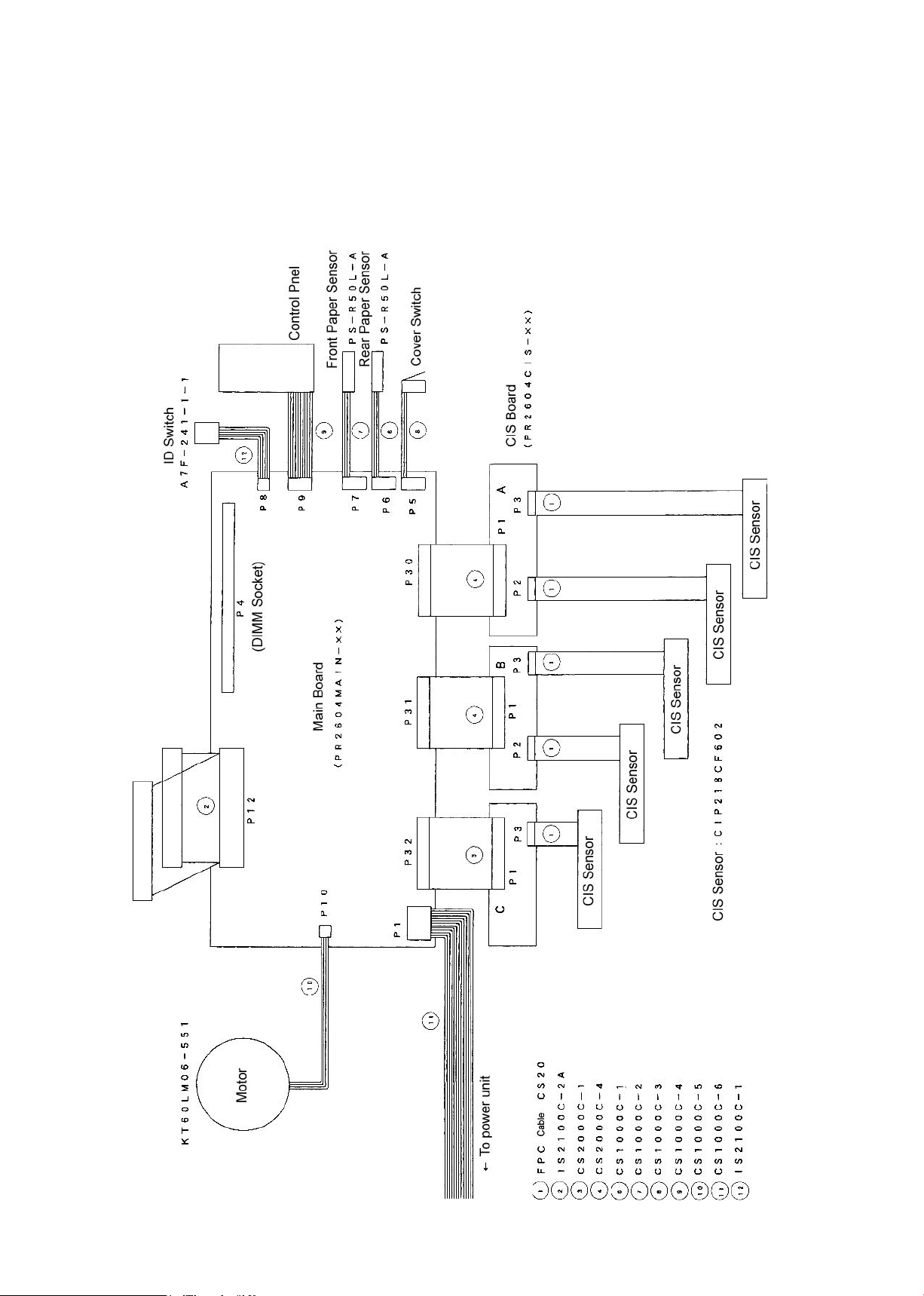
9. BOARDS AND ELECTRICAL COMPONENTS
9. BOARDS AND ELECTRICAL COMPONENTS
9.1 Wiring Diagrams
Overall Conguration
CS2000-UM-251-9370 9-1
Page 87

CS2000-UM-251-9370 9-2
9. BOARDS AND ELECTRICAL COMPONENTS
Component Layout on the Main Board
Page 88

CS2000-UM-251-9370 9-3
9. BOARDS AND ELECTRICAL COMPONENTS
Power Unit Wiring
CS2000C-6
Page 89

CS2000-UM-251-9370 9-4
9. BOARDS AND ELECTRICAL COMPONENTS
9.2 Power Supply Unit
1. Checking Voltage Levels
(1) Turn off the power for the scanner unit.
(2) Detach the connector (CN2) from the power board before checking voltage levels.
(3) Turn on the power for the scanner unit and check voltage levels between the pins listed below.
When making measurements, take care to prevent shorting the ground and output terminals.
The output voltage levels and permissible ranges are given below.
3.3 V power supply (LDS15F-3-3.3)
Pin No. Output voltage Perimssible range
1 +0V
2 +0V
3 +3.3V +3.25V to +3.35V
4 +3.3V +3.25V to +3.35V
When checking for +3.3 V, use Pin No.1 or 2 as the ground terminal.
5 V power supply (LDS15F-5)
Pin No. Output voltage Perimssible range
1 +0V
2 +0V
3 +5V +4.9V to +5.1V
4 +5V +4.9V to +5.1V
When checking for +5 V, use Pin No.1 or 2 as the ground terminal.
24 V power supply (LDS75F-24-H)
Pin No. Output voltage Perimssible range
1 +0V
2 +0V
3 +0V
4 +24V +23.5V to +24.5V
5 +24V +23.5V to +24.5V
6 +24V +23.5V to +24.5V
When checking for +24 V, use any of Pin Numbers 1 through 3 as the ground terminal.
Page 90

CS2000-UM-251-9370 9-5
9. BOARDS AND ELECTRICAL COMPONENTS
9.3 Main Control Board
1. Precautions for replacing the main board
(1) Before replacing the main board, note the feed correction value, X overlaps and Y offsets values currently
selected for the scanner, if these values can be checked. (To check these values, follow the procedure
given in "Preparations before Making Adjustments" in Section 10.2 on p. 10-3.)
(2) Use Scanning Master 21+ to make adjustments.
2. Checking voltage levels
(1) Remove the bottom cover.
(2) You will nd test pins (TP1 through TP6) in the lower left corner of the main control board. The output
voltage levels of these pins are given below:
Test pin
No. Name
TP1 GND +0V
TP2 +24V +24V +23.5V to +24.5V
TP3 +5V +5V +4.9V to +5.1V
Tp4 VCC +3.3V +3.25V to +3.35V
TP5,6 +2.5V +2.5V +2.4V to +2.6V
Output voltage Perimssible range
3. LED status
An LED is provided on the main control board.
U5: Red when the CPU is running.
U5: Remains unlit when the CPU is not running (when an error occurs).
4. Replacing the main board
(1) Before replacing the main board, note the feed correction value, X overlaps and Y offsets values currently
selected for the scanner, if these values can be checked. (To check these values, follow the steps given
in "Preparations before Making Adjustments" in Section 10.2 on p. 10-3.)
(2) Remove the bottom cover and disconnect all cables from the main control board.
(3) Remove the six screws securing the main control board.
(See "Main Board" in Section 8.9 on p. 8-10.)
(4) Detach the SDRAM from the P4 connector and install on the new main board.
(5) Attach the new main board by reversing the sequence of steps in which the old board was removed.
(6) Initialize offset by setting DIP switch 2 on the scanner unit to the ON position; then turn ON power while
pressing and holding the STOP key.
(7) Perform Calibration (white correction). (See "Calibration (white correction)" on p. 10-5.)
(8) Adjust the feed distance. (See "Adjusting feed distance" on p. 10-6.)
Page 91

CS2000-UM-251-9370 9-6
9. BOARDS AND ELECTRICAL COMPONENTS
(9) Adjust the offset (origin). (See "Adjusting offset (origin)" on p. 10-9.)
(10) Align the sensor images (X overlap, Y offset). (See "Sensor joint aligning" on p. 10-11.)
(11) Perform shading (undesired color line removal). (See "Shading (undesired color line removal)" on p.
10-14.)
(12) Perform shading (undesired gray line removal). (See "Shading (undesired gray line removal)" on p.
10-17.)
(13) Perform Color correction (using a color correction sheet). (See "Color correction" on p. 10-21.)
(14) Turn off power and set all DIP switches to the OFF position (normal operation mode).
Page 92

CS2000-UM-251-9370 9-7
9. BOARDS AND ELECTRICAL COMPONENTS
9.4 At-a-glance Guide to Adjustment Functions
Press one of the keys shown below at power-on to select the corresponding mode.
Key operations
Set DIP switch 2 to the ON position and press one of the keys shown below at power-on to select the
corresponding adjustment mode.
MODE \ KEY FORWARD REVERSE STOP
Offset initialization(*1) - - Press
Shading correction Press - -
*1: Offset initialization resets all settings stored in NVRAM to their default values.
(Feed correction, origin, X overlaps, Y offsets, and density values will be reset to their defaults.)
Page 93

CS2000-UM-251-9370 9-8
9. BOARDS AND ELECTRICAL COMPONENTS
9.5 Downloading Firmware
This section describes how to download rmware (system programs) via the SCSI interface to the ash
memory provided on the main board, to which the boot program has been downloaded.
1. Items required to download rmware
• CS2000.X le
• CS2000 scanner
• PC (Windows 95 or 98,Windows 2000/Xp and an operating environment that provides SCSI compatibility)
• OPS112 (Scanning Master 21+ Ver 4.00 or later)
• SCSI interface cable
2. Procedure
To update the rmware, follow steps (1) to (7).
To download rmware for a new main board, follow steps (8) and (9).
(1) Attach the main board to the CS2000 and use the SCSI cable to connect the CS2000 and PC.
(2) Set DIP switches 1, 2, and 3 to the ON positions and switch on power for the CS2000.
(3) Turn on power for your PC and start OPS112.
(4) When OPS112 starts, follow the steps given below to download the rmware.
1. Access the "Help" menu and select "About." At this time, a dialog box will appear.
2. Point to the icon in the window and click while pressing and holding the "Ctrl" key.
3. Click the "OK" button while pressing and holding the "Shift" key. This makes the status available for
adjustment.
4. Select "Adjust Scanner" from the "Tools" menu to display the Adjust Scanner window.
5. Select "Update Scanner/Firmware" to display the Download dialog box.
(5) Insert the oppy disk containing the rmware (lename: CS2000.X) into the oppy disk drive, click the
"View" button on the Download dialog box, select the oppy disk, and click the "OK" button.
(6) Click the "Start" button to begin downloading.
(7) After the download is complete, a message will appear. At this time, all the
panel control LEDs on the scanner should start ashing simultaneously.
After conrming the download, set all the DIP switches to "OFF," and then switch off power.
(8) When the download is complete, a message will appear. At this time, all panel control LEDs on the
scanner should start ashing at the same time.
After conrming this, turn off power and set DIP switches 1 and 3 to the OFF positions. Switch on power
again while pressing and holding the "STOP" key on the control panel.
Initialization is complete when the "POWER" LED lights up by itself, followed by the "ERROR" LED, and
then the "ERROR" LED will then go out.
(9) Next, set DIP switch 2 to the OFF position and switch on power once again for initialization to take effect.
Page 94

CS2000-UM-251-9370 9-9
9. BOARDS AND ELECTRICAL COMPONENTS
9.6 Test Mode
RAM, panel operation and SCSI ID switch operation tests can be performed in Test Mode.
1. Procedure
(1) Set DIP switch 3 to the "ON" position.
(2) Select the following combinations of DIP switches 1 and 2 to perform the tests.
DIP SW1 DIP SW2 Description
RAM check
OFF ON
ON OFF
OFF OFF
ID LED statuses
0 Error– ,Paper– ,Power–
1 Error– ,Paper– ,Power–
2 Error– ,Paper– ,Power–
3 Error– ,Paper– ,Power–
4 Error– ,Paper– ,Power–
5 Error– ,Paper– ,Power–
6 Error– ,Paper– ,Power–
7 Error– ,Paper– ,Power–
: Unlit, : Lit
The Paper LED lights if no problems are found with RAM.
The Error LED lights if a RAM error has occurred.
Panel operation test
The Power LED lights when the “FORWARD” key is pressed.
The Paper LED lights when the “REVERSE” key is pressed.
The Error LED lights when the “STOP” key is pressed.
SCSI ID switch read test
Confirm that the selected ID matches the corresponding combination of LED
statuses.
The LED statuses should be as shown below.
Page 95

10. ADJUSTMENTS USING THE SOFTWARE
10. ADJUSTMENTS USING THE SOFTWARE
10.1 Starting the Software
• Ensure that OPS112 (Scanning Master 21+ Ver 4.00 or later) is installed.
• Set DIP switch 2 on the scanner to “ON.”
(1) Connect the scanner to the PC using a SCSI cable and switch on the scanner.
(2) Start Windows (OS).
(3) Start OPS112 (SCANNING MASTER 21+).
(4) Select "About" from the "Help" menu.
(5) Click the scanner icon while pressing and holding the "Ctrl" key.
Next, click the "OK" button while pressing and holding the "Shift" key.
Icon
(6) Select "Adjust Scanner" from the "Tools" menu.
CS2000-UM-251-9370 10-1
Page 96

CS2000-UM-251-9370 10-2
10. ADJUSTMENTS USING THE SOFTWARE
(7) Select "Yes".
(8) When you click the "OK" button in the following windows, the Adjust Scanner window will appear with the
Adjust menu.
Page 97

CS2000-UM-251-9370 10-3
10. ADJUSTMENTS USING THE SOFTWARE
10.2 Preparations before Making Adjustments
Note the current feed distance adjustment and position adjustment values while making adjustments.
This enables the values to be entered directly from the keyboard to restore the scanner to its previous status
if adjustment fails.
In main board replacement, the time required for adjustment can be reduced by setting the previously noted
feed distance adjustment and position adjustment values. However, for image sensor unit replacement, all
settings must be adjusted, eliminating the need to record the previous values.
Adjustment Procedure
(1) Start Scanning Master 21+. (See p. 10-1.)
(2) Select "Adjust Feed Distance" from the "Adjust" menu.
(3) Click the "Current Value" button and note the value shown in the Feed box. After nishing, click the
"Close" button.
(4) Similarly, select "Adjust Position" from the "Adjust" menu and click the "Current Value" button. Note the
values shown in the X Overlap and Y Offset boxes and click the "Close" button.
Page 98

CS2000-UM-251-9370 10-4
10. ADJUSTMENTS USING THE SOFTWARE
10.3 Preparing a Test Chart
(1) Prepare a CS1000 adjustment test chart.
(2) Make sure that the distances (measured with a glass scale) between the two points in all pairs are
included in the chart in advance. (See the chart shown above.)
<<Tip 1>> Test chart is made of Mylar paper.
For use in normal ofce environments (normal temperatures and humidity levels), you should
only need to measure each distance once.
Make sure that each distance is measured with the utmost accuracy.
<<Tip 2>> Make sure that all staff members using this test chart select the same measurement points.
This chart has been designed with the assumption that the point shown below is used for
measurement.
<<Tip 3>> If the user-specied paper must be used for adjustments, you should make the measurements
over as long a period of time as possible to obtain good results.
Page 99

CS2000-UM-251-9370 10-5
10. ADJUSTMENTS USING THE SOFTWARE
10.4 Making Adjustments
Always follow the sequence given below when making adjustments.
1. Calibration (white correction)
2. Feed distance adjustment
3. Position adjustment
Offset adjustment
Sensor joint alignment
4. Shading (undesired color line removal)
5. Shading (undesired gray line removal)
6. Color correction
Scanner Calibration
Before beginning calibration, clean the scanner glass and scanner table surface. Any dust or dirt on this
surface may affect calibration results and resulting image quality.
Check that the calibration sheet is free of any dust or dirt.
1. Calibration (white correction)
(1) Connect the scanner to the computer. Switch on the scanner, then switch on the PC.
(2) Start Scanning Master 21+. (See p. 10-1.)
(3) Remove the white calibration sheet (200x1050mm) from its special storage box.
Clean the sensor glass surface and the document hold-down unit.
Set the document hold-down unit force setting to "High".
(4) Select "Calibration" from the "Adjust" menu.
(5) Select All in Calibration and click the Execute button.
Page 100
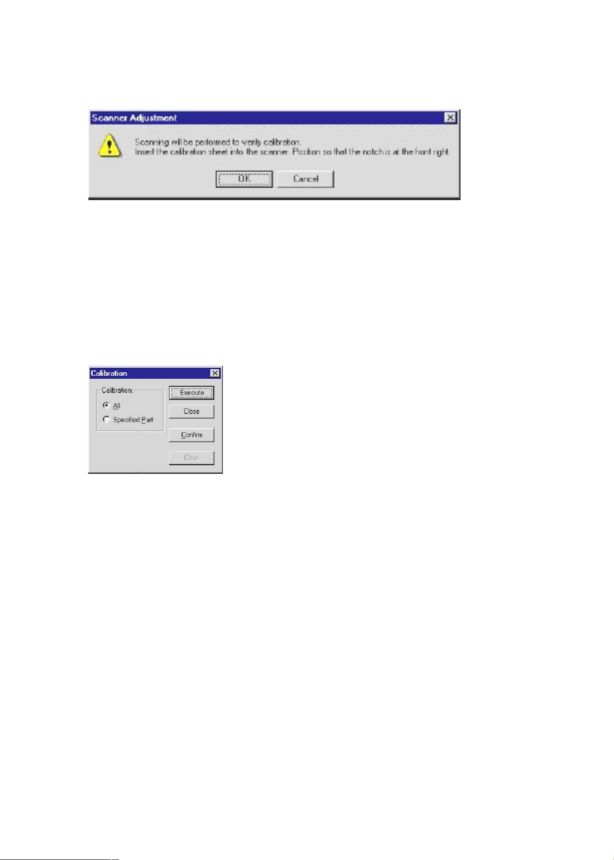
CS2000-UM-251-9370 10-6
10. ADJUSTMENTS USING THE SOFTWARE
(6) The following message is displayed. Insert the calibration sheet into the scanner as instructed.
(7) Click the OK button to start scanning.
The scanned data is displayed when scanning is complete. Colors may differ slightly for individual
sensors to make it easier to identify problem areas in calibration. This does not indicate a defect.
Check that there are no vertical streaks, such as white patches, in the scanned data.
(Streaks occur when calibration is not performed correctly due to contamination by dust or dirt.)
(8) If the data is normal, calibration is complete.
Click the Close button and exit calibration mode.
(9) If any abnormal data is observed, specify the problem areas as follows:
Select Specied Part in Calibration.
(10) The mouse arrow cursor changes to a cross cursor when moved over the data. Click the left mouse
button with the mouse positioned over the streak data. The selected area is shown in blue. Repeat this
procedure for any additional streaks.
Areas that have been selected (shown in blue) can be deselected by clicking the left mouse button again.
To deselect all selected areas, click the Clear button.
(11) Once all required areas have been specied, remove the calibration sheet and clean the glass and table
surfaces. Check the calibration sheet for dust and dirt, then click the Execute button.
(12) Return to step (5) and verify the calibration results.
 Loading...