

Page 1
USER’S MANUAL
CE LITE-50-UM-151
Page 2

Page 3

Introduction
Introduction
Thank you for purchasing Cutting Plotter CE LITE-50. This device is a cutting plotter that realizes high-speed
and high-precision work. In addition to cutting marking lms, this device can also be used as a pen plotter.
Please carefully read through this manual prior to use in order to ensure safe and proper use of the device.
This product is manufactured and sold under license from Gerber Scientic Products, Inc. for US Patent No.
5,537,135 and its foreign patents.
Notes on this Manual
(1) No part of this publication may be reproduced, stored in a retrieval system, or transmitted, in any form or by
any means, without the prior written permission of Graphtec Corporation.
(2) The product specications and other information in this manual are subject to change without notice.
(3) While every effort has been made to provide complete and accurate information, please contact your sales
representative or nearest Graphtec vendor if you nd any unclear or erroneous information or wish to make
other comments or suggestions.
(4) Not with standing the stipulations in the preceding paragraph, Graphtec Corporation assumes no liability
for damages resulting from either the use of the information contained herein or the use of the product.
Registered Trademarks
All names of companies, brands, logotypes, and products appearing in this manual are the trademarks or
registered trademarks of their respective companies.
Copyright
This User's Manual is copyrighted by Graphtec Corporation.
i
Page 4
Introduction
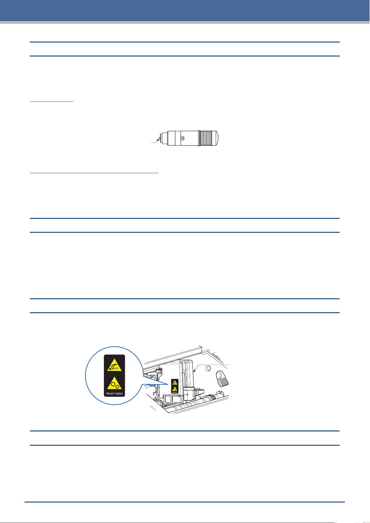
This product uses a blade. In order to prevent injury accidents due to the blade, please be very careful when
handling the cutter blade such as when attaching the cutter pen to the main unit.
Cutter Pen
The tip is a sharp blade. Be careful not to use an excessive blade depth. In addition, refrain from protruding the
blade from the tip of the cutter pen when the cutter pen is not in use.
After Attachment to the Main Unit
Refrain from touching the pen tip after the power has been turned ON and during operation as doing so is
dangerous.
Precautions on Handling the Cutter Blade
Cutter blade
Precautions After Turning the Power ON
The tool carriage and media that is set may suddenly move during work, immediately after work has ended,
and while conguring various settings. Keep hands, hair, and clothes, etc. away from moving parts and their
range of motion and refrain from placing objects on these places. When using the device, be very careful to
avoid injury due to getting hands, hair, or clothes, etc. caught in the device.
Notes regarding Warning Labels
The warning label shown below has been placed on the tool carriage of the device. Be sure to observe the
precautions listed.
Tool carriage
Notes regarding the Wording in This Manual
"Cutting" as used in this manual refers to the device operating to draw gures with a drawing pen or cut
•
media with the cutter pen.
"Media" as used in this manual collectively refers to paper, roll paper, sheet paper, and marking lm.
•
ii
Page 5

Introduction
Before Work
Be sure to read through the included "TO ENSURE SAFE AND CORRECT USE" Performing work without
•
reading this section may lead to an unexpected accident or cause a re.
Precautions when Using Curled Media
An upward curl, even when weak, can cause the media to jam.
•
Either use media that is not curled or manually x the curl so that the media has a weak downward curl that
•
ts along the main unit of the plotter.
iii
Page 6

Contents
CONTENTS
Introduction ................................................................. i
Notes on this Manual ..................................................i
Registered Trademarks ................................................ i
Copyright ...........................................................i
Cutter Pen ..........................................................ii
After Attachment to the Main Unit ........................................ii
Precautions After Turning the Power ON ...........................................ii
Notes regarding Warning Labels .................................................ii
Notes regarding the Wording in This Manual........................................ii
Before Work ................................................................ iii
Precautions when Using Curled Media ........................................... iii
Chapter 1 Notes Before Use
1.1 Standard Accessories .................................................1-2
1.2 Names and Functions of Each Component .................................1-3
1.3 Operation Panel ......................................................1-4
Types of Screens and Operations ......................................1-4
Other Displays and Operations ........................................1-5
1.4 Installing the Main Unit.................................................1-6
Installation Space ...................................................1-6
1.5 Media Size and Cutting Area ............................................1-7
Compatible Media Sizes..............................................1-7
Cutting Area .......................................................1-7
1.6 Installing the Driver and Software ........................................1-8
1.7 Connecting and Turning ON the Power . . . . . . . . . . . . . . . . . . . . . . . . . . . . . . . . . . . . 1-9
1.8 Connecting a Computer ...............................................1-10
1.9 Settings when Turning the Power ON for the First Time ......................1-11
Chapter 2 Basic Operations
2.1 Setting the Tool ......................................................2-2
Adjusting the Blade Depth of the Cutter ..................................2-2
Reference and Precautions regarding Blade Depth Adjustment ...............2-2
Setting the Tool ....................................................2-3
2.2 Setting the Media Set Levers............................................2-4
2.3 Setting the Push Rollers................................................2-5
Moving the Push Rollers .............................................2-5
Push Roller Setting Positions ..........................................2-5
2.4 Loading Sheet Media ..................................................2-6
Loading the Media Up Against the Push Rollers ...........................2-6
Loading the Media upon Releasing the Push Rollers .......................2-8
Unloading Sheet Media ..............................................2-9
2.5 Conrming the CONDITION NO. (Cutting Condition).........................2-10
2.6 Precautions when Creating Data ........................................ 2 -11
Notes regarding the Cutting Origin Position ..............................2 -11
Notes regarding the Cutting Area......................................2-12
iv
Page 7

2.7 Sending Cutting Data.................................................2-13
2.8 Ordinary Care ......................................................2-14
Cleaning the Cutter Pen .............................................2-14
Chapter 3 Cutting along Printed Data
3.1 What is Printing & Cutting? .............................................3-2
3.2 Simple Printing & Cutting ...............................................3-3
3.3 Registration Mark Scanned Printing & Cutting...............................3-5
3.4 Types and Arrangement of Registration Marks ..............................3-6
Registration Mark Shapes ............................................3-6
Positions for Registration Mark Arrangement..............................3-7
Automatic Registration Mark Position Detection ...........................3-8
3.5 Flow of Creating Registration Marks to Cutting ..............................3-9
Graphtec Pro Studio.................................................3-9
Cutting Master 4 ...................................................3-12
Graphtec Studio ...................................................3-15
Contents
Chapter 4 Convenient Functions
4.1 Cutting Roll Media ....................................................4-2
Assembling the Roll Media Stocker .....................................4-2
Loading and Scanning Roll Media ......................................4-4
Setting the Page Length..............................................4-8
4.2 Cutting using the Carrier Sheet ..........................................4-9
Loading Media onto the Carrier Sheet ..................................4-10
Loading the Carrier Sheet ...........................................4 -11
4.3 Plotting with the Drawing Pen ..........................................4-14
Setting the Drawing Pen in the Pen Adapter .............................4-14
Setting the Pen Adapter .............................................4-15
4.4 Cutting from a USB Memory ...........................................4 -17
Saving Data on a USB Memory .......................................4-17
Cutting upon Loading USB Memory Data ...............................4 -17
Cutting Barcode-equipped Data.......................................4-18
4.5 Cutting Multiple Media using the Same Data (Copy Function)..................4 -19
Copying Multiple Cuts on a Single Media................................4-19
Copying Repeatedly on Multiple Media .................................4-21
4.6 Cutting upon Specifying the Cutting Position...............................4-22
4.7 Expanding the Cutting Area ............................................4-23
4.8 Aborting and Pausing during a Cut ......................................4-24
4.9 Withdrawing the Tool Carriage..........................................4-25
Chapter 5 Detailed Settings
5.1 Individually Registering Settings for Cutting Conditions .......................5-2
5.2 Adjusting the Cutting Quality ............................................5-3
Selecting the Tool and Setting the Offset Value............................5-3
Setting the Cutting Force .............................................5-4
Setting the Offset Force ..............................................5-4
Setting the Condition Priority ..........................................5-5
v
Page 8

Contents
Setting the Distance Adjustment .......................................5-5
Setting the Blade Tip Orientation Initialization Position ......................5-6
5.3 Adjusting the Cutting Time..............................................5-7
Setting the Speed...................................................5-7
Setting the Acceleration ..............................................5-7
Setting the Tool Up Speed ............................................5-8
5.4 Cutting Thick Media ...................................................5-9
What is the Tangential Mode? .........................................5-9
Setting the Tangential Mode...........................................5-9
Setting the Overcuts................................................5-10
5.5 Performing Cut Tests . . . . . . . . . . . . . . . . . . . . . . . . . . . . . . . . . . . . . . . . . . . . . . . . . 5 -11
Cutting 1 Test with the Setting Values ..................................5 -11
Cutting 3 Tests to include Setting Values ± 1.............................5 -12
Conrming the Cut Test .............................................5 -12
5.6 Registration Mark Scan Settings ........................................5-13
Setting the Scan Mode ..............................................5-13
Conrming Registration .............................................5-14
Correcting the Registration Mark Position ...............................5-16
Setting Automatic Registration Mark Position Detection ....................5 -19
5.7 Adjusting the Media Operation..........................................5-20
Setting the Pre Feed Operation .......................................5-20
Setting the Auto Pre Feed ...........................................5-21
Setting the Initial Feed ..............................................5-21
Setting the Media Width Detection .....................................5-22
5.8 Setting Commands ..................................................5-24
Selecting the Command .............................................5-24
Setting the HP-GL Origin Point .......................................5-24
Setting the HP-GL Model Emulated ....................................5-24
Setting the GP-GL Step Size .........................................5-25
5.9 Setting the Operation Panel............................................5-26
Language Selection ................................................5-26
Selection of Unit for Lengths .........................................5-26
Setting the Beep for Key Operation ....................................5-26
Chapter 6 Troubleshooting
6.1 Responding to Trouble .................................................6-2
When the device does not operate even when the power is turned ON .........6-2
Operation is Irregular ................................................6-2
6.2 Conrming Error Messages .............................................6-3
GP-GL Command Errors .............................................6-3
HP-GL Command Errors .............................................6-3
ARMS Errors ......................................................6-4
Other Error Displays.................................................6-4
6.3 Conrming the Operation of the Main Unit..................................6-5
Plotting the Self Test Pattern ..........................................6-5
Plotting the Test Pattern ..............................................6-5
Adjusting the Width Detection Sensor ...................................6-6
Main Unit Diagnosis Test .............................................6-6
vi
Page 9

Contents
6.4 Conrming the Main Unit Firmware Version.................................6-7
Appendix
A.1 Standard Specications ................................................A-2
A.2 Supply Items ........................................................A-3
A.3 Appearance Drawing . . . . . . . . . . . . . . . . . . . . . . . . . . . . . . . . . . . . . . . . . . . . . . . . . .A-4
A.4 Menu Tree ..........................................................A-5
A.5 List of Initial Values ...................................................A-9
INDEX ....................................................................I-1
vii
Page 10

Page 11

Chapter 1 Notes Before Use
An overview of this device and connections with a computer are explained in this chapter.
1.1 Standard Accessories
1.2 Names and Functions of Each Component
1.3 Operation Panel
Installing the Main Unit
1.4
1.5
Media Size and Cutting Area
1.6 Installing the Driver and Software
Connecting and Turning ON the Power
1.7
1.8
Connecting a Computer
1.9 Settings when Turning the Power ON for the First Time
Page 12
Chapter 1 Notes Before Use
1.1
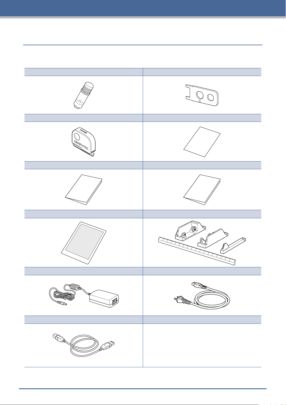
Please conrm that all accessories are included. If any of the accessories are missing, please immediately
contact your store of purchase or our company's customer service.
Cutter Set (Standard Blade) [PM-BS-001] 1 set Blade Tip Cap Jig 1 unit
Cross Cutter [PM-CC-001] 1 unit Software Activation Code 1 sheet
SETUP MANUAL 1 copy TO ENSURE SAFE AND CORRECT USE 1 copy
Standard Accessories
Carrier Sheet (13-inch) 1 sheet Roll Media Stocker 1 set
AC Adapter 1 unit AC Cable 1 unit
USB Cable (1.5 m) 1 unit
1-2
Page 13
Chapter 1 Notes Before Use
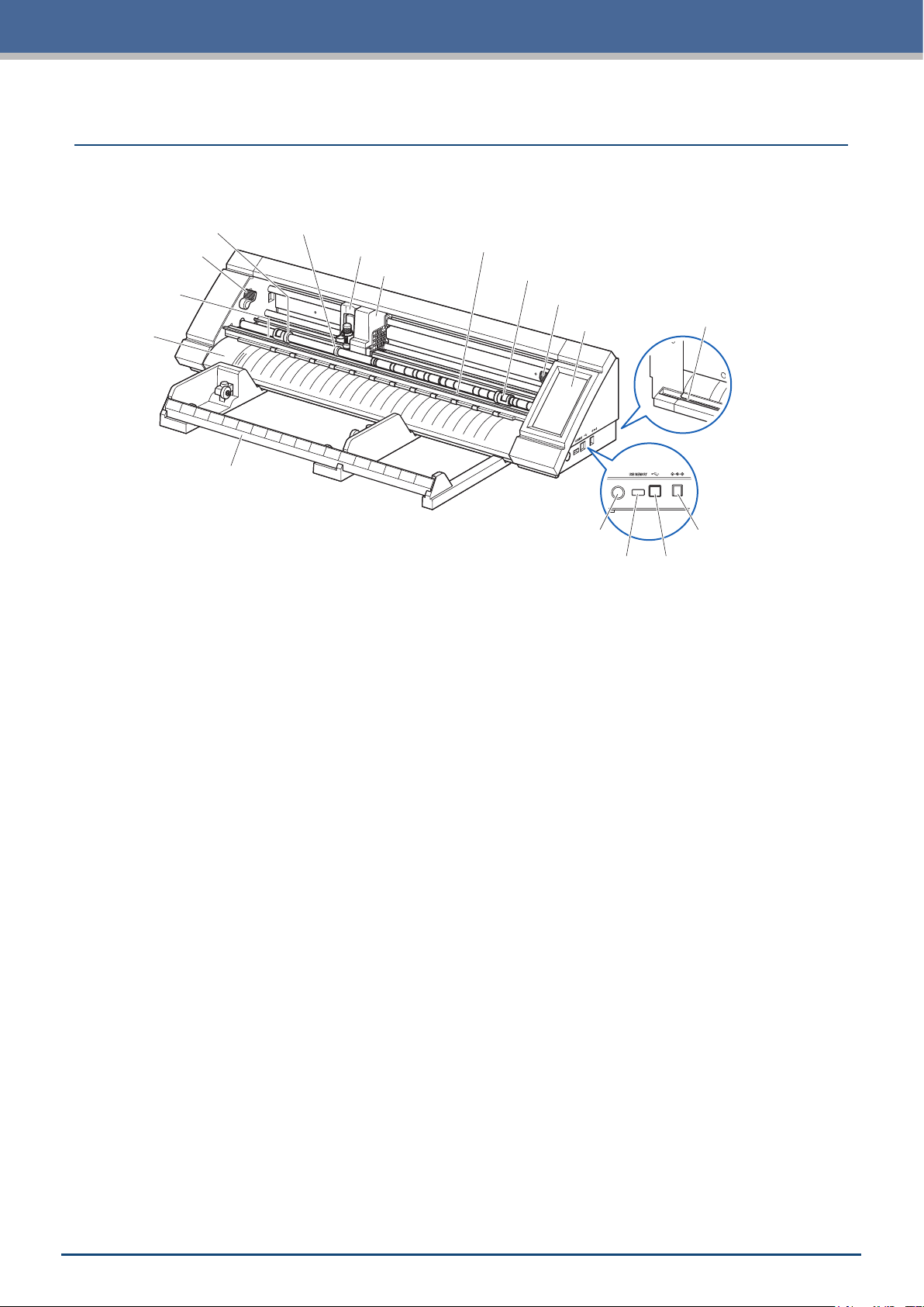
1.2
Media sensor
Names and Functions of Each Component
Push roller Media holding roller (movable)
Tool holder
Tool carriage
Roll media stocker
Push roller positioning guide
Push roller
Media set lever - right
Operation panel
Power switch Power supply connector
USB memory-dedicated port USB interface
Cutter groove
Operation panel: Used to operate the device and congure various settings.
Media set lever-right: Used to raise/lower the push roller when setting media and x (3 positions) / release
the media. Adjust this lever according to the width of the media.
Media set lever-left: Used to raise/lower the push roller when setting media and x/release the media.
Push rollers: Touches the media to x/transport the media. Adjust this roller according to the type
and size of the media.
Push roller positioning guide:
Sets the push rollers at the position of the indicated marking.
Tool carriage: Drives the tool left/right and scans registration marks and barcodes.
Tool holder: Holds the tool and drives it up/down.
Media holding roller (movable):
Holds down media to prevent low cutting quality and malfunction of register mark
detection. Set it in the center or the most lifted part of the media.
Media sensor: Scans media.
Front Guide: Sets the media at the position of the indicated marking.
Roll media stocker: Holds roll media.
Power switch: Used to turn the power ON/OFF.
USB memory-dedicated port:
Used to connect and load data from a USB memory.
USB interface: Used to connect the device with a computer.
Power supply connector: Used to connect the power cable.
Cutter groove:
Used when registrationping roll media with the cross cutter.
1-3
Page 14
Chapter 1 Notes Before Use
1.3
Operation Panel
Types of Screens and Operations
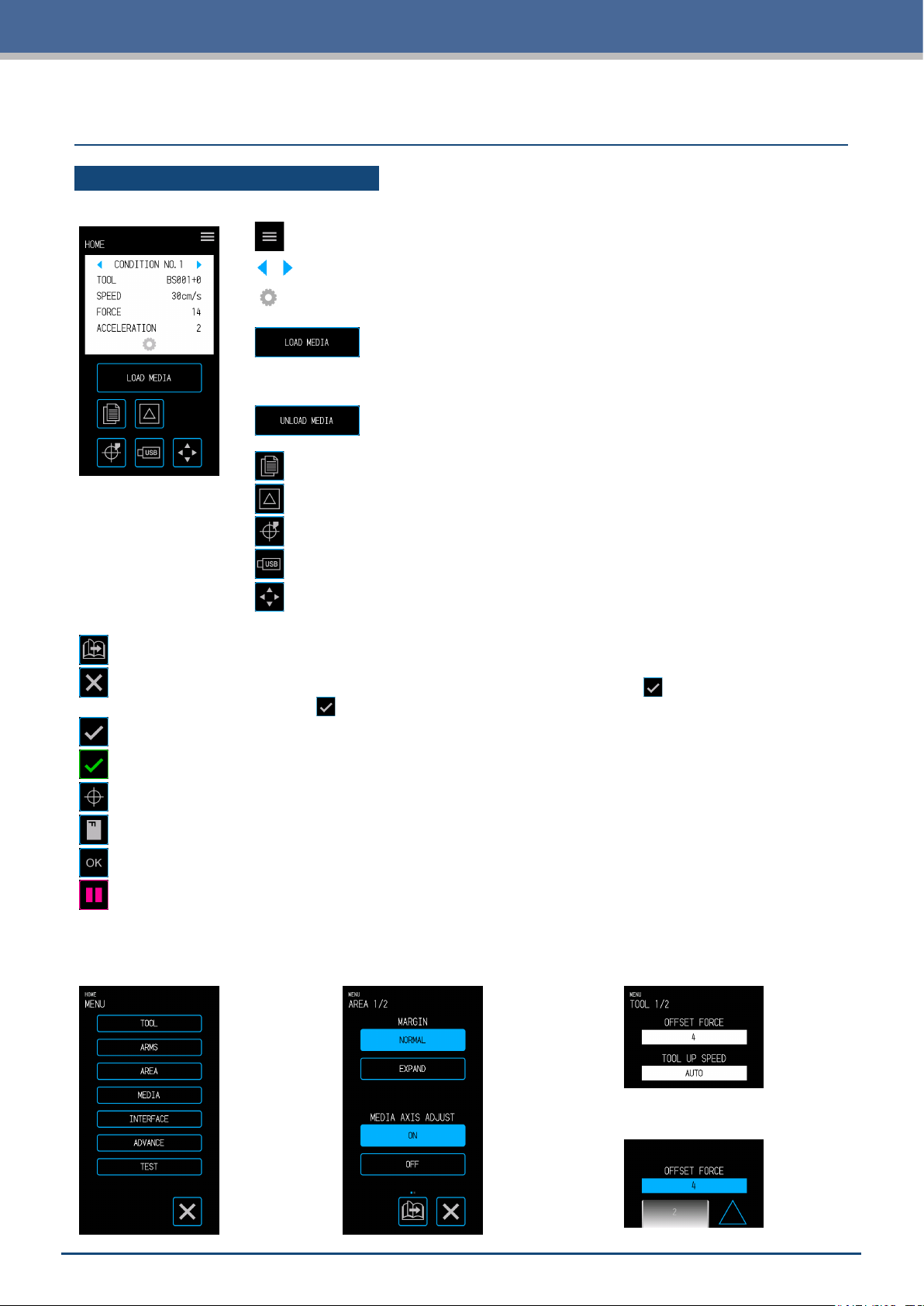
HOME Screen and Functions of Buttons
"MENU" button:
"CONDITION NO. Selection" buttons:
"CONDITION" button:
setting screen.
"LOAD MEDIA" button:
Used to transition to the Load Media screen.
The following screen is displayed when media is set.
"UNLOAD MEDIA" button:
Used to Unload Media that has been set.
"COPY" button:
"CUT TEST" button:
"HOME" button:
"USB" button:
Used to transition to the copy mode.
Used to move the tool carriage to the home point.
Used to transition to the menu for cutting from a USB memory.
Used to transition to the "MENU" screen.
Used to select the CONDITION NO.
Used to transition to the CONDITION (cutting condition)
Used to transition to the cut test screen.
Position key:
Other Buttons
"Page" button:
"Exit" button:
"Conrm" button:
"Execute" button:
"Origin" button:
"Cutting Area" button:
"OK" button:
"Stop" button:
Used to transition to the next page on the same tier level.
Used to exit the current screen. When touched before the
where the
Used to conrm settings.
Used to execute settings.
Used to congure the plot origin.
Used to display th cutting area of the media that has been loaded.
Used to conrm the position of the tool moved with the position keys.
Stops the cutting operation.
Menu Selection Screen
This screen is used to select setting
items. Please touch the button to set.
Used to transition to the position key screen.
(Conrm) in a screen
(Conrm) is displayed, the screen is exited without setting the item.
Different Button Colors
Light blue indicates the selected setting.
Please touch the button to set
.
Different Display Boxes
White boxes can be touched to
transition to the input screen.
1-4
Light blue boxes display the
current setting value.
Page 15
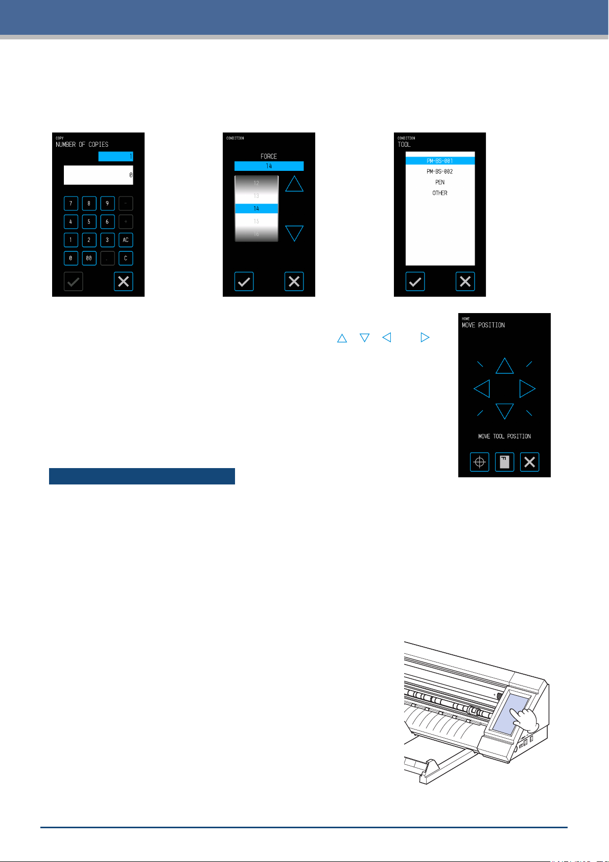
Input Screen
Number Input
Touch the buttons to input a
numb er.
Drum Selection
Rotate the drum to scroll through
the list and select a setting value.
Chapter 1 Notes Before Use
List Selection
Touch the item you wish to select
from the list to set the item.
Position Keys
The tool carriage or media moves to each direction when the " ", " ", " " and " "
position keys are touched.
The movement will be started from slow speed when the position keys are touched.
The movement speed changes to fast speed when key is touching more than a few
seconds.
Other Displays and Operations
Instruction Screen
If the power is turned ON while in a state where the media set levers are released, the message "SET THE
•
MEDIA SETTING LEVER." will appear on the operation panel. Once the media set levers are lowered, the
"LOAD MEDIA" screen will be displayed.
When setting the media, a message regarding the media or the push rollers may appear. In such case,
•
operate the device by following the on-screen instructions.
Operate the device by following the on-screen instructions also when other operation related messages
•
appea r.
Sleep Release
The touch panel function will be turned off (Sleep Mode) in a few minutes
when it is not touched.
To restart it, touch the touch panel.
1-5
Page 16
Chapter 1 Notes Before Use
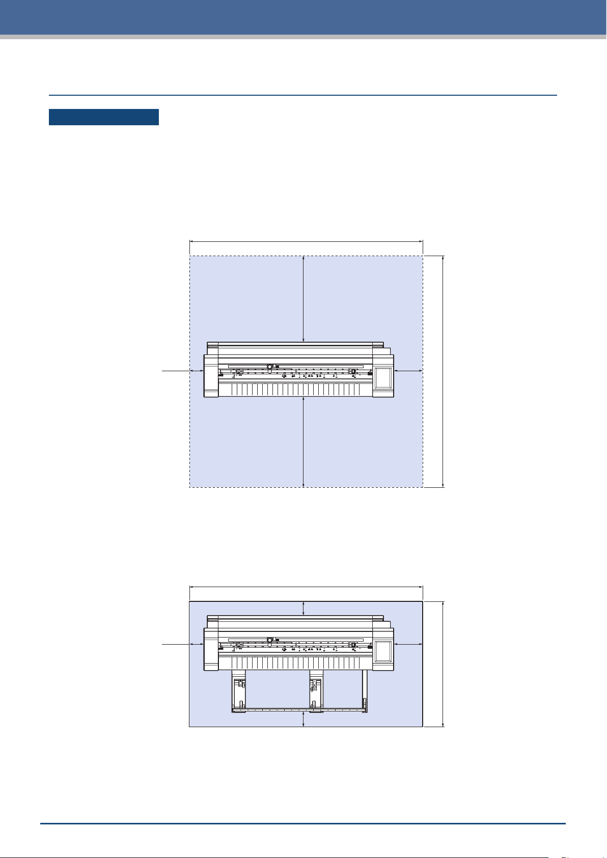
1.4
Installing the Main Unit
Installation Space
Secure enough space to install the device so that the cutting operation is not affected.
The space required to the front and rear of the device will vary depending on the size of the media being
•
used.
Refrain from placing obstacles in front of or behind the main unit that will interfere with transportation of the
•
media.
Installation Space when Using Carrier Sheets
934mm
296mm
50mm
100mm
834mm
311mm
When using the roll media stocker and installing the device on a table, use a table that is leveled and solid with
a top panel that is at least 934 × 502 mm in size.
When using roll media, refrain from placing obstacles in front of or behind the main unit that will interfere with
•
transportation of the media.
934mm
50mm
50mm
50mm
100mm
502mm
1-6
Page 17
Chapter 1 Notes Before Use
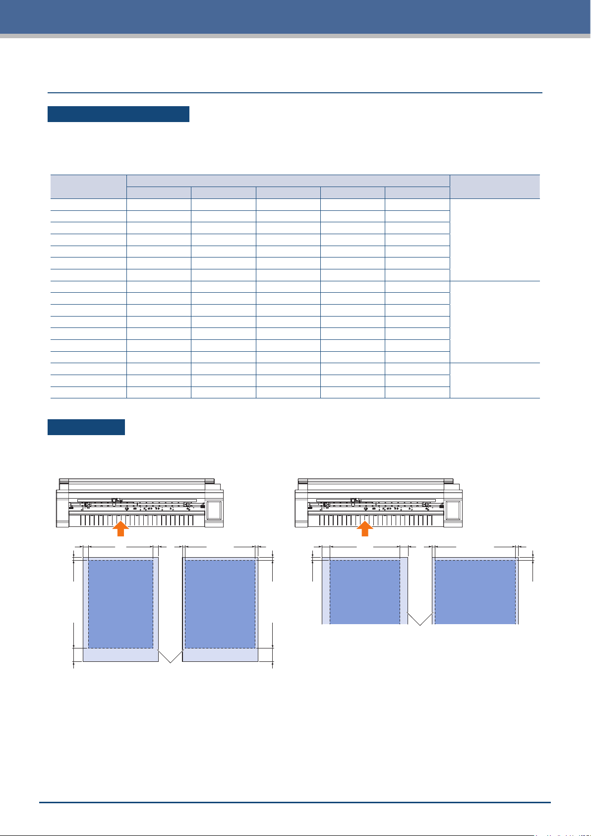
1.5
Media Size and Cutting Area
Compatible Media Sizes
This cutter is able to use only width of standard media size as shown in the table below.
Use the carrier sheet when the media width is other than below.
For more information on the carrier sheet, refer to "4.2 Cutting using the Carrier Sheet".
Compatible
Media Width
210.0mm A4
215.9 mm 8.5inch
220.0mm OK
250.0mm B4
25 7. 0m m B4
279.4mm 11i n ch
29 7. 0m m A3
304.8mm 12inch
320.0mm OK
329.0mm A3+
353.0mm B3
364.0mm B3
381.0m m 15inch
420.0mm A2
431.8mm 17inch
508.0mm 20inch
ISO A/JIS A JIS B ISO B Inch Non-Standard
Size
Position of right side
Media Set Lever
1
2
3500.0mm B2
Cutting Area
The cutting area and cutting direction will be as shown below.
Sheet Media Roll Media
10mm 10mm
5mm30mm
Cutting Area
Sheet Media
When margin is normal
5mm 5mm
Cutting Area
When margin is narrowed
5mm30mm
15mm 15mm
5mm
When margin is normal
Cutting Area
5mm 5mm
5mm
Cutting Area
Sheet Media
When margin is narrowed
1-7
Page 18

Chapter 1 Notes Before Use
1.6
Download the device driver and application software from Graphtec website to install these on your computer.
Installing the Driver and Software
Notes on Compatible OS
The software for this device is compatible with the following OS environments:
Graphtec Pro Studio & Cutting Master 4 & Divece Driver (Windows)
Windows 10 (32-bit / 64-bit), Windows 8.1 (32-bit / 64-bit), Windows 8 (32-bit / 64-bit),
Windows 7 (32-bit / 64-bit)
Graphtec Studio & Cutting Master 4 (Mac)
Macintosh Mac OS X 10.11 - 10.7 / mac OS 10.13 - 10.12 (Graphtec Studio is also compatible with Mac OS X 10.6)
Please conrm the latest compatible OS environment on our company website.
Installing the Cutting Plotter Driver (Windows)
Download the devoce driver from Graphtec website website.
For installation procedures, refer to the documented procedures available on the website.
URL: http://www.graphtec.co.jp/en/imaging/celite/support.html
The device driver for Mac does not need install.
CAUTION
Do not connect this device and the computer with a USB cable before installing the printer driver.
Connecting these prior to installation may prevent the printer driver from being properly installed.
Installing Graphtec Pro Studio (Windows)
Download the software from the following Graphtec website.
URL: http://www.graphtec.co.jp/en/imaging/celite/support.html
For installation procedures, refer to the documented procedures available on the website.
Installing Cutting Master 4 (Windows/Mac)
Download the software from the following Graphtec website.
URL: http://www.graphtec.co.jp/en/imaging/celite/support.html
For installation procedures, refer to the documented procedures available on the website.
Installing Graphtec Studio (Mac)
Download the software from Graphtec website.
URL: http://www.graphtec.co.jp/en/imaging/celite/support.html
For installation procedures, refer to the documented procedures available on the website.
1-8
Page 19
Chapter 1 Notes Before Use
1.7
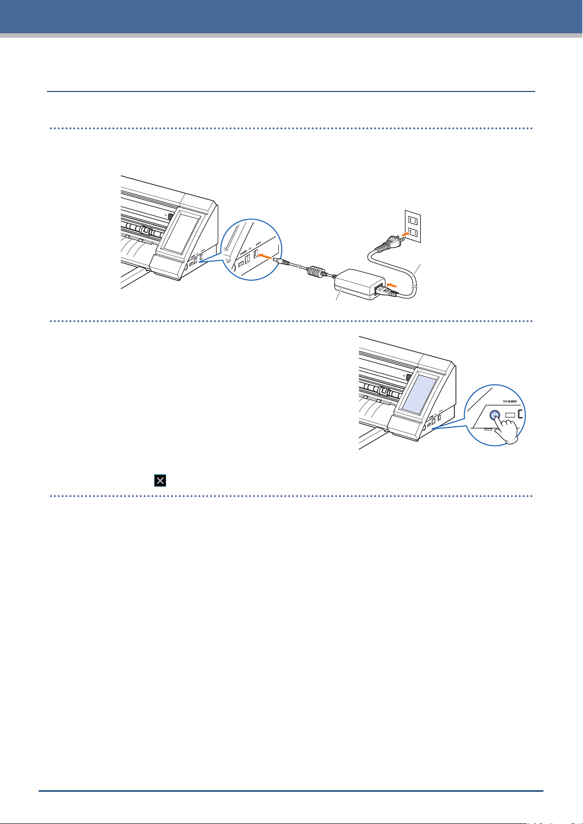
Connect this device and the AC outlet via the standard accessory of AC adapter, and then turn ON the power.
Connecting and Turning ON the Power
1. Connect the AC adapter and the AC cable (1). Connect the AC adapter to the power supply connector of
this device (2). Connect the AC cable to the AC outlet of specied voltage (3).
(3)
(2)
AC Cable
(1)
AC Adapter
2. Press the power switch to turn ON the power.
Conrm that the touch panel has started up.
When turning ON the power, wait at least 20 seconds to turn
on the power after the power was turned OFF.
The device may fail when immediately the power turned ON,
after the power was turned OFF.
After the power was turned ON when the media set lever
•
was not set, the "SET THE MEDIA SETTING LEVER." is
displayed.
At this time, lower the set lever, and then the "LOAD MEDIA" is displayed.
Then touch the
(Exit) to exit to the HOME menu.
1-9
Page 20
Chapter 1 Notes Before Use
1.8
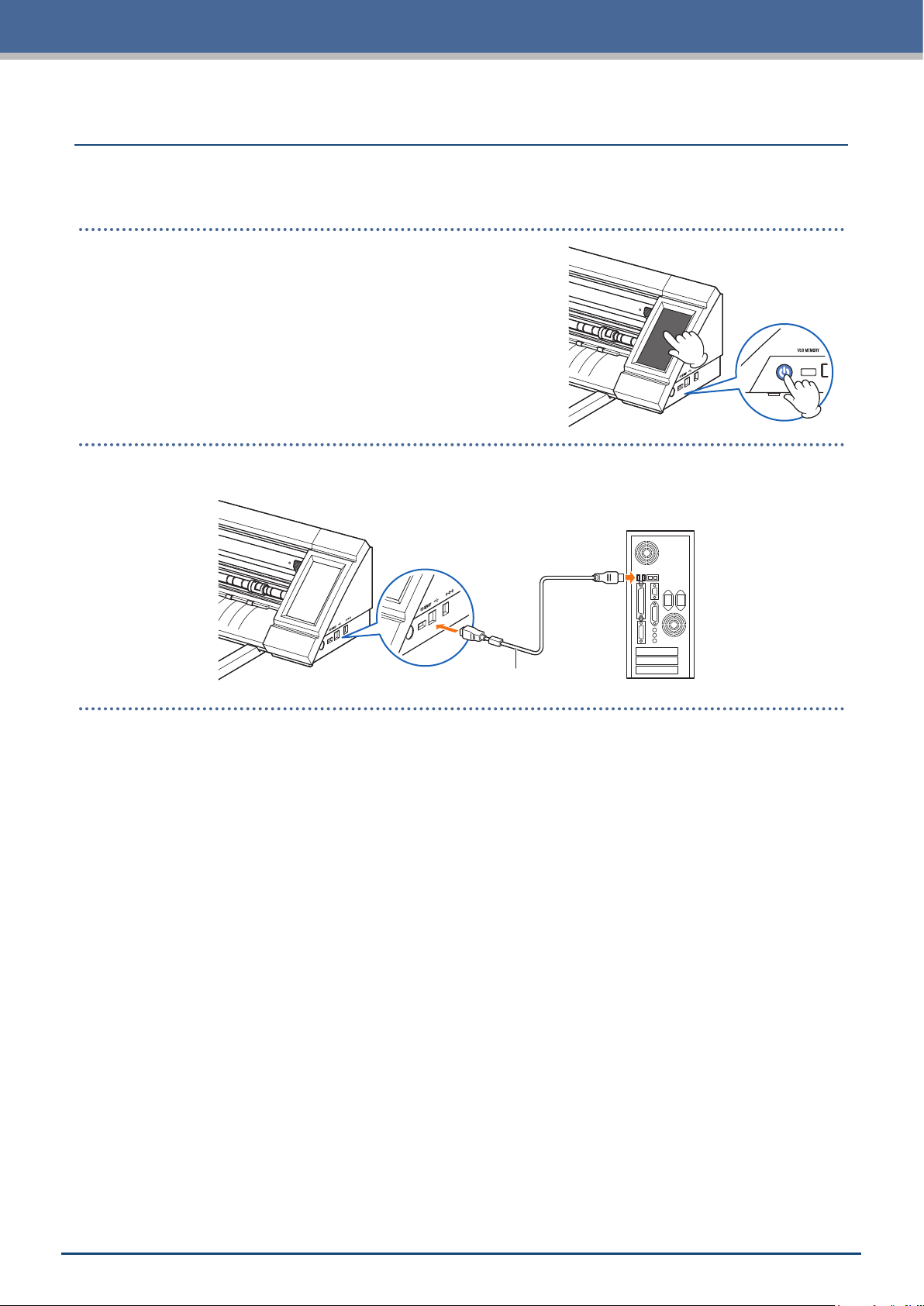
Connect this device and a computer by using the supplied USB Cable.
For Windows: Connect the USB cable after the device driver was installed to the PC.
•
Connecting a Computer
1. Turn OFF the power.
Touch the touch panel and conrm that the screen does not
start up.
2. Connect this device and the computer by the USB cable.
Computer
USB Cable
1-10
Page 21
Chapter 1 Notes Before Use
1.9
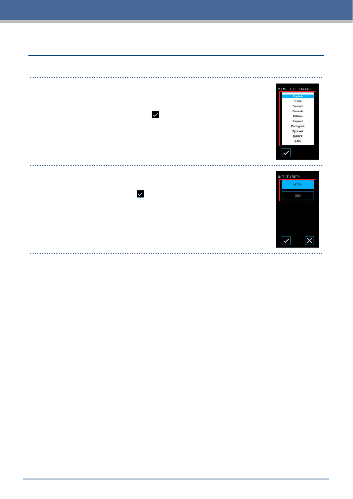
When the device is started up for the rst time, it will be necessary to set the language and the unit for lengths.
Language Selection
When the power of this device is turned ON for the rst time, the startup screen will be
followed by a language selection screens.
Select the language used, and then touch the
Selection of Unit for Length
Once the language has been set, the screen for selecting the unit for length will appear.
Select the unit used, and then touch the
Settings when Turning the Power ON for the First Time
(Conrm).
(Conrm).
Once the unit for lengths has been set, the HOME screen will be displayed.
1-11
Page 22

Page 23

Chapter 2 Basic Operations
Perform basic cuts by following the items explained in this chapter.
2.1 Setting the Tool
2.2 Setting the Media Set Levers
2.3 Setting the Push Rollers
Loading Sheet Media
2.4
2.5
Conrming the CONDITION NO. (Cutting Condition)
2.6 Precautions when Creating Data
Sending Cutting Data
2.7
2.8
Ordinary Care
Page 24

Chapter 2 Basic Operations
2.1
The cutter pen (PM-BS-001) is an consumption goods.
Purchase a new cutter pen when the cutter blade becomes dull.
Setting the Tool
Adjusting the Blade Depth of the Cutter
The blade depth needs to be adjusted in order to perform optimal cutting. Perform the test cutting several times
to set an optimal blade depth.
CAUTION
Be careful when handling the cutter blade to avoid cutting your hands, etc.
•
An excessive blade depth will damage the cutter blade and cutting mat or lead to wasteful consumption of
•
media. Keep the blade depth less than the thickness of the media.
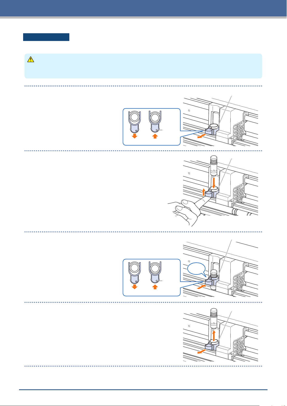
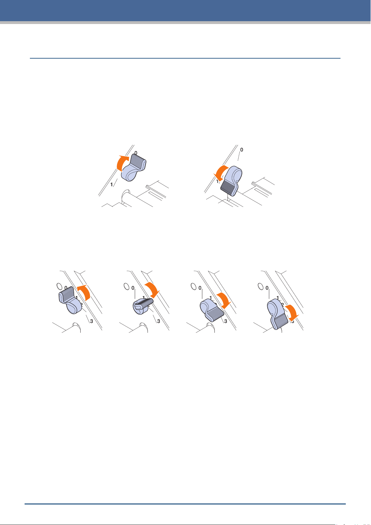
The blade depth is adjusted by turning the tip of the cutter pen.
Align the number with the red line to adjust the blade depth.
Aligning a larger number to the line will increase the blade depth. The blade depth is
changed in approximately 0.1 mm for each number. The blade depth is able to adjust
to a maximum of approximately 1 mm.
CAUTION
Do not turn the cap clockwise (towards 10) from the state where the blade tip is not
protruding (at 0). Similarly, do not turn the cap further counter-clockwise (towards 0)
past the state where the blade tip is protruding by 1 mm (at 10). Doing either of these
may damage the cutter pen.
Reference and Precautions regarding Blade Depth Adjustment
Commonly available vinyl sticker sheets are congured of two layers - a sheet with an adhesive and a backing.
Adjust the blade depth so as not to penetrate the backing.
Adjust the blade depth so that the vinyl sheet is penetrated
and a light trace of the cut is left on the backing.
Good
Vinyl Sheet
Backing
When adjusting the blade depth, start with a shallow blade depth and make adjustments to a greater depth.
•
The appropriate blade depth will vary depending on the thickness of the media. Make adjustments and
•
perform cut tests every time the type of media is switched.
Cutter Blade
An excessive blade depth will be cause to dull cutting not
only, it damages the tip of blade also.
No Good
Vinyl Sheet
Backing
Cutter Blade
2-2
Page 25
Chapter 2 Basic Operations
Setting the Tool
To attach the tool, insert the tool into the tool holder completely, and then x the tool by the locking lever.
CAUTION
Don't touch to the tool while it is moving, it is extremely dangerous.
•
Be careful not to injure yourself with the cutter blade when setting the tool.
•
1. Pull the locking lever to open the lock.
2. Insert the cutter pen to the tool holder while holding it.
Locking Lever
Locking
indicator
LockUnlock
Locking Lever
3. Push the locking lever until it clicks to hold the cutter pen.
Conrm the locking indicator became the white.
LockUnlock
4. Pull the locking lever to open the lock, and then remove the
cutter pen from the tool holder.
Locking Lever
Click
Locking
indicator
Locking Lever
2-3
Page 26
Chapter 2 Basic Operations
2.2
Set the media set levers to the locked position, except the following conditions.
Moving the push roller position or removing jammed media.
When this device will not be used for a long period, set the media set levers to the released position.
The "SET THE MEDIA SETTING LEVER." is displayed when the media set levers did not set to the locked
position when the HOME menu is selected.
Setting the Media Set Levers
Setting the Media Set Lever - Left
Set the media set lever - left to the lock position to hold the media with the left side push roller.
Release
Lock
Setting the Media Set Lever - Right
There are three lock positions for the media set lever - right.
The lock position depends on the width of media.
Set the media set lever - right to the correct position.
Refer to the "1.5 Media Size and Cutting Area" to set the right side Media Set Lever to correct position.
Release
When the media lock lever was set to incorrect position, the message of correct position will be displayed.
Set the media set lever - right to the correct position according with the message
Lock 1
Lock 2
Lock 3
Media Width and Lock Position
Lock 1: A4 / 8.5” / 220mm / B4 / 11” / A3
Lock 2: 12” / 320mm / A3+ / CARRIER SHEET / B3 / 15” / A2
Lock 3: 17” / 500mm / 20”.
2-4
Page 27
Chapter 2 Basic Operations
2.3
Adjust the positions of the left and right push rollers to suit the width of the media.
Set the push rollers positioned onto both edges of the media.
Moving the Push Rollers
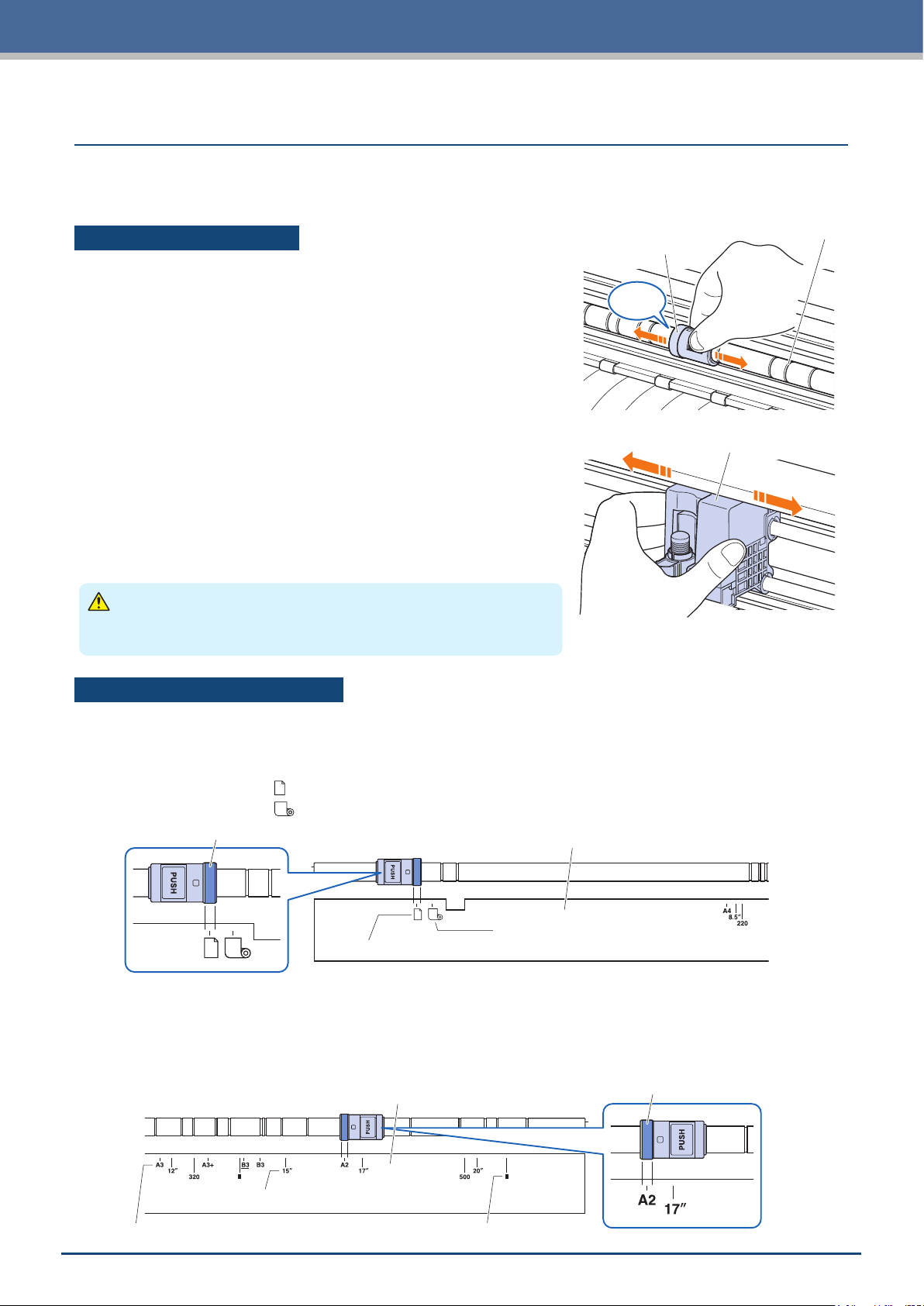
To move the push rollers, raise the media set levers and release the
push rollers. Squeeze the "PUSH" part with your ngers, and then
move the push roller left and right while pressing the "PUSH" part. If
the "PUSH" is in a position that is difcult to press, rotate the roller
so that it can easily be pressed. When the push roller reaches to the
desired position, release the "PUSH" part and place it in the position
where it "clicks" into the positioning groove. After setting the push
roller, move slightly to the left and right without pressing the "PUSH"
part to check that it ts in the positioning groove.
If the tool carriage obstructs the setting the push rollers, release
the left and right media set levers and slowly move the tool carriage
away. Gently hold the tool carriage from both sides. Holding this at a
different position or forcefully moving it may cause damage. The tool
carriage that has been moved will return to its home position when
the power is turned ON.
Setting the Push Rollers
Push Roller
Click
Positioning Groove
Tool carriage
CAUTION
Be sure to operate/move the media set lever, push rollers, and tool
carriage when operating the load media menu.
Push Roller Setting Positions
Left Side Push Roller Setting Positions
Align the "media pressing portion" of the push roller with the position of the push roller positioning guide to set
the push roller in place.
Align the push roller to the " " position when using the sheet media or the carrier sheet.
Align the push roller to the " " position when using the roll media.
Media Pressing Portion
Roll Media
Sheet Media/Carrier Sheet
Push Roller Positioning Guide
Right Side Push Roller Setting Positions
Set the "Media pressing portion" of the push roller according to the width of media.
Align the media pressing portion with the markings on the top row for standardized sizes (mm), the middle row
for standardized sizes (inch), and the bottom row for non-standardized sizes or the carrier sheet.
Push Roller Positioning Guide
Media Pressing Portion
Standardized Sizes (mm)
Standardized Sizes (inch)
Non-standardized sizes/Carrier Sheet
2-5
Page 28
Chapter 2 Basic Operations
2.4
Use the standard media size of sheet media. Use the carrier sheet when using the non standard media size of
sheet media.
Depending on the type of media (especially with high transparency), the media cannot be set because CE
•
LITE-50 cannot detect the leading edge /width /position of the media. In this case, use a carrier sheet or
disable the Media width detection.
Depending on the type of media, the center of the media may be lifted up because the push rollers cannot
•
hold down the media sufciently. In this case, move the Media holding rollers (movable) to the position where
the media is lifted up. When the media is load at, move them to the right push roller.
Move the Media holding rollers (movable) after raising the Media set levers.
•
Limp or too much thin media cannot be cut.
•
For more information on the carrier sheet, refer to "4.2 Cutting using the Carrier Sheet".
For more information on the media width detection, refer to "5.7 Setting the Media Width Detection".
Supported sheet media size: A4 - 20inch (refer to "1.5 Media Size and Cutting Area")
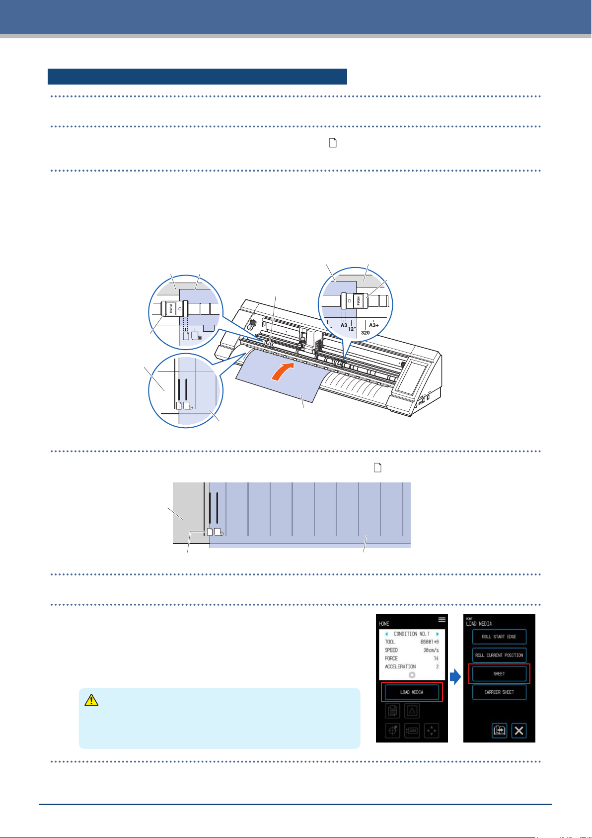
Loading the Media Up Against the Push Rollers
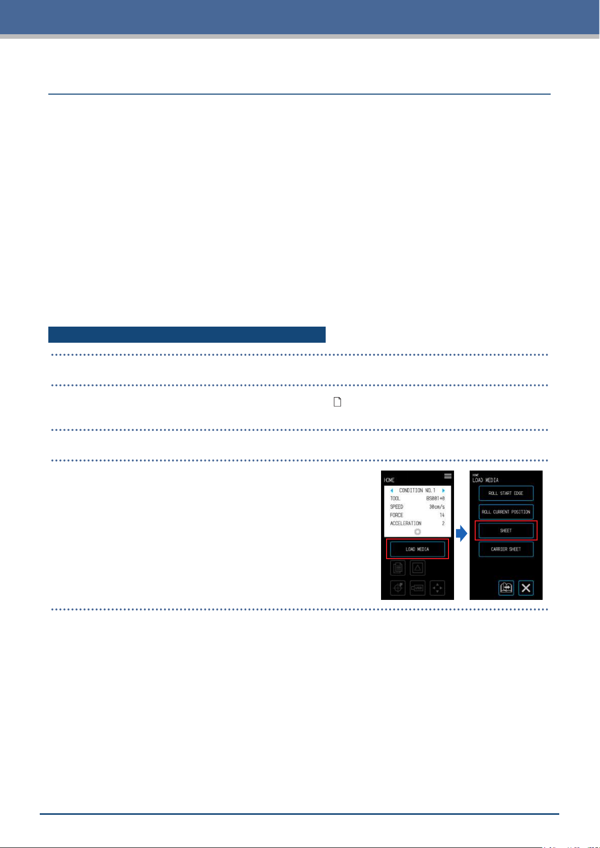
Loading Sheet Media
1. Raise the media set levers and release the push rollers.
2. Set the push roller on the left side at the position of the " " mark.
Set the push roller on the right side according to the width of the sheet media.
3. Lower the media set levers on both sides to lock the push rollers.
4. On the "HOME" screen, touch the "LOAD MEDIA" − "SHEET".
2-6
Page 29
Chapter 2 Basic Operations
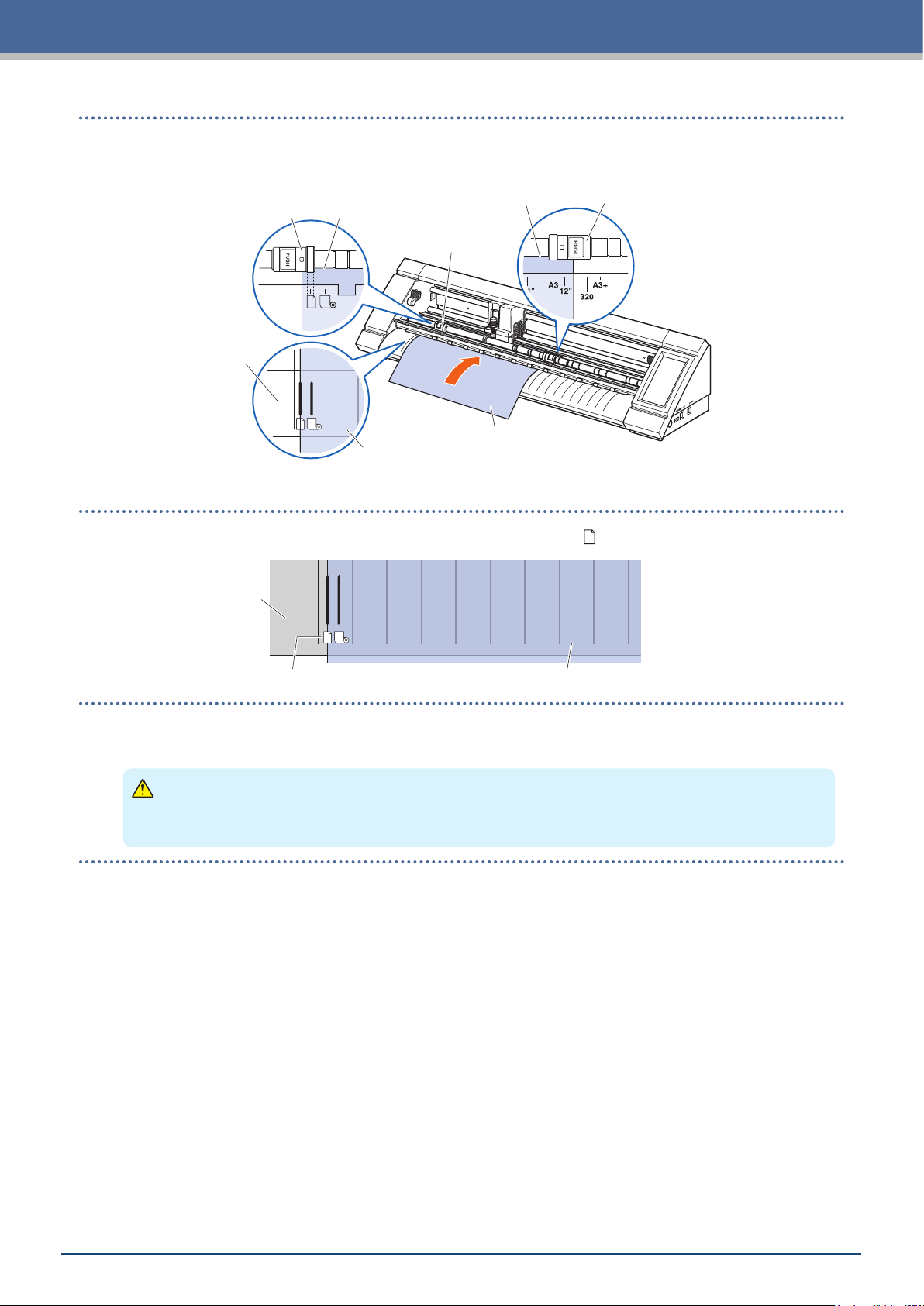
5. Evenly position the edge of the sheet media up against the push rollers. Pass the sheet media under the
push roller positioning guide and load it so that it is parallel with the front guide.
Push Roller Edge of Sheet Media
Front Guide
Sheet Media
Set to be parallel
Edge of Sheet Media Push Roller
Push Roller
Sheet Media
6. Align the left edge of the sheet media with the " I " marking of the " " mark on the front guide.
Front Guide
Sheet Media / Carrier Sheet Marking Sheet Media
7. The width, front edge, and rear edge of the media are scanned and the sheet media is loaded. If an error
is displayed, operate the device by following the on-screen instructions.
CAUTION
When the "SHEET" is touched, the media and tool carriage will start moving. Be careful to avoid contact
with your body or any object.
2-7
Page 30
Chapter 2 Basic Operations
Loading the Media upon Releasing the Push Rollers
1. Raise the media set levers and release the push rollers.
2. Set the push roller on the left side at the position of the " " mark.
Set the push roller on the right side according to the width of the sheet media.
3. Insert the front edge of the sheet media in until it reaches the cutting mat (white translucent mat) behind
the push rollers.
Pass the sheet media under the push roller positioning guide and load it so that it is parallel with the front
guide.
If the sheet media is inserted too far, there may be cases when the media cannot be scanned.
Cutting Mat
Edge of Sheet Media
Edge of Sheet Media Cutting Mat
Push Roller
Push Roller
Push Roller
Front Guide
Sheet Media
Sheet Media
Set to be parallel
4. Align the left edge of the sheet media with the " I " marking of the " " mark on the front guide.
Front Guide
Sheet Media / Carrier Sheet Marking Sheet Media
5. Lower the media set levers on both sides and lock the push rollers.
6. On the "HOME" screen, touch the "LOAD MEDIA".
When the "SHEET" is touched, the width, front edge, and rear
edge of the media are scanned and the sheet media is loaded.
If an error is displayed, operate the device by following the on-
screen instructions.
2-8
CAUTION
When the "SHEET" is touched, the media and tool carriage will
start moving. Be careful to avoid contact with your body or any
object.
Page 31

Chapter 2 Basic Operations
Unloading Sheet Media
1. Conrm that the cutting operation has stopped.
2. Touch the "UNLOAD MEDIA" and the media will be unloaded from the front of the
device.
2-9
Page 32

Chapter 2 Basic Operations
2.5
Select a CONDITION NO. to which a cutting condition for the tool is registered and conrm the setting details.
That which is displayed in the currently selected CONDITION NO. and cutting condition.
Select the CONDITION NO. to use with the "
conrm the setting details.
For more details on setting the CONDITION NO. and cutting conditions, refer to "5.1
Individually Registering Settings for Cutting Conditions".
Conrming the CONDITION NO. (Cutting Condition)
" and " " on the "HOME" screen and
2-10
Page 33

Chapter 2 Basic Operations
2.6
Precautions when Creating Data
Notes regarding the Cutting Origin Position
The position of the cutting origin will vary depending on the settings for "Cutting Area". Create cutting data in
reference to the following:
Tilt correction: Enabled
Margin: Normal/Expanded
The cutting origin (0, 0) will always
be near the vertex of the media edge
regardless of the state in which the
margin has been set.
Media Transport
Direction
As the area between the media edge
•
approximately 5 mm inward from the
edge is outside of the cutting area,
the media will not be cut in this area
even if cutting data exists.
For information on the cutting origin when scanning registration marks, refer to "3.3 Printing & Cutting upon
•
X
Y
Cutting Origin
Scanning Registration Marks".
For information on how to change the cutting origin, refer to "4.6 Cutting upon Specifying Cutting Positions".
•
For information on how to change the tilt correction, refer to "3.2 Simple Printing & Cutting".
•
For information on how to change the margin settings, refer to "4.7 Expanding the Cutting Area".
•
Tilt correction: Disabled
Margin: Normal
The cutting origin (0, 0) will be the
vertex of the effective cutting area.
The point approximately 5 mm inward
from the front edge and approximately
10 mm from the left edge.
Media Transport Direction
Y
X
Cutting
Origin
Approx.
10 mm
Approx. 5 mm
Tilt correction: Disabled
Margin: Expanded
The cutting origin (0, 0) will be the
vertex of the effective cutting area.
The point approximately 5 mm inward
from the front edge and the left edge.
Media Transport Direction
Y
X
Cutting
Origin
Approx. 5 mm
Approx. 5 mm
2-11
Page 34

Chapter 2 Basic Operations
Notes regarding the Cutting Area
The cutting area will vary depending on the media and the settings for "Cutting Area". Create cutting data in
reference to the following:
Media: Sheet media
Tilt correction:
Enabled/Disabled
, Margin: Normal
Front Edge: 5 mm / Left/Right: 10 mm / Rear Edge: 30 mm
Media Transport Direction
Y
X
Cutting Area
5mm
30mm
10mm10mm
Media: Carrier sheet
Margin: Normal/Expanded
Front Edge: 5 mm / Left/Right: 5 mm / Rear Edge: 5 mm
Media Transport Direction
Y
X
Cutting Area
5mm
Media: Sheet media
Tilt correction:
Enabled/Disabled
, Margin: Expanded
Front Edge: 5 mm / Left/Right: 5 mm / Rear Edge: 30 mm
Media Transport Direction
Y
X
Cutting Area
5mm
30mm
5mm5mm
5mm
5mm5mm
For information on how to change the margin settings, refer to "4.7 Expanding the Cutting Area".
•
For more information on the carrier sheet, refer to "4.2 Cutting using the Carrier Sheet".
•
2-12
Page 35

Chapter 2 Basic Operations
2.7
From a computer, send cutting data created in one of the environments listed below.
For more details, refer to the manuals respective to each software.
Dedicated software: Graphtec Pro Studio Plus (optional)
•
Dedicated software: Graphtec Pro Studio
•
Dedicated software: Graphtec Studio for Mac
•
Dedicated plug-in software: Cutting Master 4
•
Dedicated Windows Driver
•
Sending Cutting Data
2-13
Page 36

Chapter 2 Basic Operations
2.8
Conduct ordinary care while being careful of the items listed below.
Refrain from lubricating the mechanical section.
•
To clean the main unit, wipe the unit with either a dry cloth or a cloth soaked in a diluted neutral detergent.
•
Refrain from using substances such as paint thinner, benzene, or alcohol, etc. as these will damage the
surface.
If the cutting mat is dirty, clean it by wiping is with a dry cloth.
•
If the cutting mat is very dirty, wipe it with a cloth moistened with
alcohol or a diluted neutral detergent.
Dust or dirt, etc. attaching to the sensor unit which scans the media or the
•
roller unit that transports the media can cause the device to malfunction.
Regularly wipe these components with a cloth or cotton swabs moistened
with alcohol or a diluted neutral detergent.
* Absolutely refrain from using benzene, paint thinner, etc.
If the Y-rail sliding surface has become dirty, gently wipe off the dirt with a clean dry cloth.
•
* Lubricant seeps out onto the sliding surface. Avoid forcefully wiping this off.
Ordinary Care
Cutting Mat
Push Roller
Media Sensor
Storage Method
Be careful of the following items for storage when the device will not be used.
Be sure to remove the tool from the tool holder when storing the device.
•
Prevent dust from accumulating by covering the main unit with a cover cloth cover.
•
Refrain from storing the device in a location exposed to direct sunlight or subject to high temperatures and
•
humidity.
Raise the media set levers and place the push rollers in their unlocked state for storage.
•
Cleaning the Cutter Pen
Media scraps, etc. attached to the tip of the cutter blade will lower the quality of the cuts.
Regularly clean the cutter pen to remove any media scraps, etc.
CAUTION
Be very careful when handling the cutter blade to avoid cutting your hands, etc.
•
Clean the tip of the cutter blade with air or a soft material. Using a stiff material can cause the blade to chip or break.
•
1. Align the red line on the cutter pen with "0" to place it in a state
where the blade is not protruding.
Blade Tip Cap
Blade Tip
Cap Jig
2. Turn the Blade Tip Cap to counterclockwise to remove it by using
the Blade Tip Cap Jig.
Attach the Blade Tip Cap Jig to the Blade Tip Cap, and then
remove the Blade Tip Cap while holding the number part of
cutter pen as shown in the picture.
Cutter Blade
3. Clean the removed blade tip cap and cutter blade with air or a
soft material.
4. Attach the Blade Tip Cap to the Cutter pen, and then manually turn the Blade Tip Cap clockwise to install it.
Securely tighten the Blade Tip Cap by using the Blade Tip Cap Jig.
2-14
Page 37

Chapter 3 Cutting along Printed Data
"Printing & Cutting" which involves cutting the media along printed data is explained in this
chapter along with registration marks.
3.1 What is Printing & Cutting?
3.2 Simple Printing & Cutting
3.3 Registration Mark Scanned Printing & Cutting
3.4 Types and Arrangement of Registration Marks
3.5 Flow of Creating Registration Marks to Cutting
Page 38

Chapter 3 Cutting along Printed Data
3.1
Stickers, etc. can be created by placing a cutting line in the media along with the cutting of printed data.
In order to realize this printing & cutting function, this device has been equipped with two functions. Use each
function according to the environment of use.
What is Printing & Cutting?
Cutting Line
Plot
Simple Printing & Cutting
With this function, the edge of the media is scanned and cutting lines are made upon predicting the cutting
positions of the printed data based on the position of this scanned edge. This method is useful when working
with media on which registration marks cannot be printed.
However, as the edge of the media needs to be scanned, there are conditions such as the media having to be
a standardized size and the cutting line being affected by the positioning precision of the printer used.
Edge of Media
Cutting Line
Plot
Registration Mark Scanned Printing & Cutting
The data is printed on the media with registration marks (reference lines) added. These registration marks are
scanned with the sensor and cutting lines are made upon predicting the cutting positions of the printed data
based on the positions of these scanned registration marks.
Because this method is affected by the base, etc. of the media, media on which registration marks are difcult
to scan cannot be used.
Registration Mark
Cutting Line
Plot
3-2
Page 39

Chapter 3 Cutting along Printed Data
3.2
When the media is loaded, the position and tilt of the media is scanned in order to layer the cutting line over the
printed media.
As this method does not use registration marks, it is not affected by issues such as not being able to scan
•
the registration marks depending on the image on the base.
However, as this method is affected by the print positioning precision of the printed media, it is recommended
that a printer with excellent print positioning precision be used.
Be sure to use the standard size of media.
•
Transparent media cannot be used. When using transparent media, also use release media that is not transparent.
•
Media with roughly cut edges and media that is damaged can cause erroneous scans.
•
This method cannot be used with roll media.
•
For available media setting on the software,you must congure the standard paper size the same as that of
•
your congured plotter.
Simple Printing & Cutting
1. On the "HOME" screen, select the CONDITION NO. to use by using the " " and " "
and set the tool.
2. From the "MENU" screen, open the "AREA 1/2" screen and set
"MEDIA AXIS ADJUST" to "ON".
3. Touch the (Exit) to return to the "HOME" screen and load the
printed media to make a sample cut.
4. Measure the displacement of the cutting line from the printed media that has been loaded.
Deciding the Offset Volume
Measure the offset volume (displacement amount) along the X-axis (vertical) and Y-axis (lateral) between
the position at which you intended to make the cut and the position that was actually cut.
In the image below, the values are negative for both X and Y.
Y Value
+–
Media Transport Direction
X Value
–+
Intended Cutting Position
Origin
Media
X
Actually
Cut Position
Y
3-3
Page 40

Chapter 3 Cutting along Printed Data
Deciding the Distance Adjustment Volume
Measure the lengths of X (vertical) and Y (lateral) for the shape of the data (printed media) and the
shape that was cut.
Media Transport Direction
Data Value X
Cut Value X
Origin
Data Value Y
Cut Value Y
"AREA 1/2" screen, proceed to the "AREA
2/2" screen, and input the offset and the
correction value for distance adjustment.
The space inside the white boxes for
numerical input can be touched to transition
to the input screen. Input the values for the
offset value in the X/Y directions and the
distance adjustment volumes in the X/Y
directions.
Intended Shape to be Cut
Shape
Actually Cut
5. From the "MENU" screen, open the
Media
How to Input Numbers
Offset Volume:
Input the displacement amount and conrm the input with the
.
Distance adjustment volume:
Input the enlargement/reduction rate (%) and conrm the
input with the
.
When the cut value is 50 mm and the data value is 51 mm,
(Data value [51] – Cut value [50) / Cut Value [50]) × 100 (%) = 2
so set +2% (after being set, the cut will be made at a length of
51 mm).
6. Touch the (Exit) to return to the "HOME" screen, load the printed media, and perform the cutting
operation.
7. To make multiple cuts, send the data while changing the media.
Printing & cutting will be performed according to the tilt when the printed media is set.
3-4
Page 41

Chapter 3 Cutting along Printed Data
3.3
With this method, cuts will be made upon scanning the registration marks (reference lines) drawn on the media.
High-precision cutting is realized with this method as displacement of the printing position is adjusted when
cutting the outline of a printed shape or when re-cutting media.
If the registration marks cannot be scanned due to a registration mark scanning error or when the positions
•
are off despite the registration marks being scanned, refer to "5.6 Registration Mark Scan Settings" and
change the settings.
Registration Mark Scanned Printing & Cutting
1. Create printed media on which registration marks have been drawn (refer to "3.4 Types and Arrangement
of Registration Marks).
2. On the "HOME" screen, select the CONDITION NO. to use by using the " " and " "
and set the tool.
3. Load the printed media on which registration marks have been drawn.
4. Touch the (Position) to open the "MOVE POSITION" screen.
5. Use the " ", " ", " " and " " to move the tool to the
registration mark scan starting area.
If the current position of the tool is far away from the registration
mark scan starting area, it may take time to search for the
registration marks or the process may even end in an error.
Registration Mark Type 1 Registration Mark Type 2
Y
X
Media Transport Direction
Registration Mark
Scan Starting Area
Y
X
Media Transport Direction
Registration Mark
Scan Starting Area
6. Touch the (Exit) to return to the "HOME" screen and perform the cutting operation.
7. To make multiple cuts, send the data while changing the media.
Printing & cutting will be performed according to the tilt when the printed media is set.
3-5
Page 42

Chapter 3 Cutting along Printed Data
3.4
The types of registration marks that can be scanned with this device are explained in this chapter.
Upon understanding the details, create the registration marks using the dedicated application software of
"Graphtec Pro Studio", "Cutting Master 4", or "Graphtec Studio for Mac".
Download the application software from our company website.
URL: http://www.graphtec.co.jp/en/imaging/celite/support.html
Types and Arrangement of Registration Marks
Registration Mark Shapes
The shape of the registration marks can be one of two types - Type 1 or Type 2.
Create the registration marks as plot data using the dedicated application software. Registration marks unique
to the application software cannot be used.
Line thickness of registration marks: 0.3 - 1.0 mm
Registration mark size: 5 - 20 mm
Registration Mark Type 1
Used when registration marks are preferably left
outside of the cutting area. The cutting area within
the media will become smaller to account for the size
of the registration marks.
Y
Registration Mark Type 2
Used when the cutting area is preferably kept as
close as possible to the size of the media. Care must
be taken as the registration marks will be placed
within the cutting area. Cutting cannot be performed
near the registration marks.
Y
X
Media Transport Direction
X
Media Transport Direction
3-6
Page 43

Positions for Registration Mark Arrangement
Registration marks are arranged on the edge of the media with a margin.
Chapter 3 Cutting along Printed Data
Unit: mm
Numbers within brackets
"( )" are for when the
margin is expanded
1136
X
Y
Registration Mark Type 1 Registration Mark Type 2
Media Transport Direction
10 (5) 10 (5)
1132
Y
X
16 (11) 16 (11)
The area required to scan the registration marks is as shown below.
When a plot other than a registration mark exists in the registration mark scanning area, the plot may be
•
mistaken for a registration mark.
Be sure to clean the media so that it is free of dirt and dust, etc. Dirt or dust may be mistaken for a
•
registration mark.
Create the registration marks using a contrast that is easy to scan such as black on white media. Adjust the
•
registration mark settings when using the media other than white or glossy media. (Refer to "5.6 Registration
Mark Scan Settings")
Y
Registration Mark Type 2 Registration Mark Type 2
X
Media Transport Direction
6
Registration Mark Scanning Area Registration Mark Scanning Area
If a registration mark scan error occurs, congure the registration mark scan settings. (Refer to "5.6
•
6
Y
X
6
Unit: mm
6
Registration Mark Scan Settings")
For details on creating registration marks using the dedicated application, refer to "3.5 Flow of Creating
•
Registration Marks to Cutting".
3-7
Page 44

Chapter 3 Cutting along Printed Data
Automatic Registration Mark Position Detection
The area of "A" is scanned from the registration mark scan starting position (position of the tool), and if a
registration mark is not located in the area of "A", the area of "B" is scanned.
Registration marks can be recognized as registration marks if they exist within the areas of "A" or "B".
Media Transport Direction
Registration Mark
ScanStarting Position
B
B
AA
100100
100
It may be difcult to scan registration marks depending on the state of the media being used.
Transparent media
•
Media with blurry printed registration marks
•
Bent media
•
Media with a dirty surface
•
Media having a thickness of 0.6 mm or more
•
Laminated media (depending on the type and state of lamination)
•
Media on which black registrations mark lines are not printed on a white surface.
•
When using media on which black registrations mark lines are not printed on a white surface, set AUTO MARK
SCAN to OFF. (Refer to "Setting Automatic Registration Mark Position Detection")
Otherwise, congure the registration mark scan settings. (Refer to "5.6 Registration Mark Scan Settings")
100
3-8
Page 45

Chapter 3 Cutting along Printed Data
3.5
The ow from creating the registration marks using the dedicated application to cutting the plot is explained in
this chapter.
Flow of Creating Registration Marks to Cutting
Graphtec Pro Studio
[1] Creating the registration marks
1. Using the "Rectangle" tool in Graphtec Pro Studio, create a rectangle over
the design.
A margin is required at the edge of the media when creating the rectangle.
As the printing position may vary depending on the printer used to print
the design, it is recommended that a few extra millimeters be allowed for
the margin.
Y
Media Transport Direction
X
Margin
2. Select the rectangle, and then select "Effects" – " Rectangle to Contour
Cut Mark...".
3. On the "Design Central" screen, select the type of registration mark.
4. Click the "Options".
The "Graphtec Mark Options" screen
will appear where you can specify
the length and line thickness of the
registration marks.
After specifying each item, close the
screen.
5. On the "Design Central" screen, click the
"
".
Registration marks will be created over the
design.
Media Transport Direction
X
Y
Registration Mark Type 1 Registration Mark Type 2
3-9
Page 46

Chapter 3 Cutting along Printed Data
[2] Creating data for printing & cutting
1. Create data for printing & cutting.
2. Select the printing data, and then select "Effects" – "Contour
Cut...".
On the "Design Central" screen, select the offset for the outline.
Y
Registration Mark Type 1 Registration Mark Type 2
Media Transport Direction
X
3. On the "Design Central" screen, click the " ".
Cutting data will be created over the design.
[3] Printing the created data
1. Print the created data.
CAUTION
Be careful to observe the following items as doing otherwise will lead to not being able to scan the
registration marks and perform the cutting.
Set the enlargement/reduction scale to 100%.
•
Set the printing position (center / bottom left, etc.) to "Do Not Change".
•
Y
Registration Mark Type 1 Registration Mark Type 2
Media Transport Direction
X
Cutting Data
3-10
Page 47

[4] Cutting the printed media
1. Load the printed media onto CE LITE-50.
(Refer to "2.4 Loading Sheet Media")
2. Click the "Cut Contour" icon.
3. The "Cut Contour" screen will launch.
In order to match the orientation in
which the media has been loaded, set
ROTATE to "
When the "Cut Contour" screen is
•
displayed for the rst time, the "Add
Device" screen will be displayed.
Follow the on-screen instructions to
select "CE LITE-50" for the model
name and "Graphtec USB" for the
connection destination.
".
Chapter 3 Cutting along Printed Data
Y
Registration Mark Type 1 Registration Mark Type 2
Media Transport Direction
X
4. Click the "Send".
5. A conrmation screen will appear.
Move the tool to the registration mark (red square) at the top
left and click the "OK".
Scanning of the registration marks will begin, and once all
of the registration marks have been scanned, the cutting will
begin.
Y
Registration Mark Type 1 Registration Mark Type 2
Media Transport Direction
X
Move tool
here
3-11
Page 48

Chapter 3 Cutting along Printed Data
Cutting Master 4
[1] Creating the registration marks
1. Using the "Rectangle" tool in Illustrator or CorelDRAW, create a rectangle
over the design.
A margin is required at the edge of the media when creating the rectangle.
As the printing position may vary depending on the printer used to print
the design, it is recommended that a few extra millimeters be allowed for
the margin.
2. After selecting the rectangle, when using Illustrator,
access the File menu and select "Cutting Master4" –
"Registration Marks".
When using CorelDRAW, go to the tool bar and select
"Launch" – "Registration Marks (CM4)".
When using a version of CorelDRAW that is X7
•
or earlier, the registration marks screen will be
displayed when it is selected from the application
launcher.
The screen to the right is the screen that appears
•
when it is launched from Illustrator.
Y
Media Transport Direction
X
Margin
3. Specify the registration mark type, line thickness, and
length.
Place a check in "Convert rectangle".
4. Close the registration marks screen.
Registration marks will be created over the design.
Y
Registration Mark Type 1 Registration Mark Type 2
Media Transport Direction
X
3-12
Page 49

[2] Creating data for printing & cutting
1. Create data for printing & cutting.
It is recommended that the printing data and cutting data be
created on separate layers.
[3] Printing the created data
1. Print the created data.
Before printing the data, set the layer containing the cutting data to be hidden.
Chapter 3 Cutting along Printed Data
Y
Registration Mark Type 1 Registration Mark Type 2
Media Transport Direction
X
Cutting Data
CAUTION
Be careful to observe the following items as doing otherwise will lead to not being able to scan the
registration marks and perform the cutting.
Set the enlargement/reduction scale to 100%.
•
Set the printing position (center / bottom left, etc.) such that the relative positioning of the position of
•
the created document and the printed results are the same.
3-13
Page 50

Chapter 3 Cutting along Printed Data
[4] Cutting the printed media
1. Load the printed media onto CE LITE-50.
(Refer to "2.4 Loading Sheet Media")
2. When using Illustrator, access the File menu and select "Cutting Master4" – "Cut / Plot".
When using CorelDRAW, go to the tool bar and select "Launch" – "Cut / Plot (CM4)".
When using a version of CorelDRAW that is X7 or earlier, this can be selected from the application
•
launcher.
Before selecting the cutting plot, set the layer containing the printing data to be hidden.
Y
Registration Mark Type 1 Registration Mark Type 2
Media Transport Direction
X
3. The "Cut / Plot" screen will launch.
In order to match the orientation in which the
media has been loaded, set ROTATE to "
When the "Cut / Plot" screen is displayed
•
for the rst time, the "Add Device" screen
will be displayed.
Follow the on-screen instructions to select
"CE LITE-50" for the model name and
"Graphtec USB" for the connection
destination.
".
4. Click the "Send".
5. A conrmation screen will appear.
Move the tool to the registration mark (red square) at the top
left and click the "OK".
Scanning of the registration marks will begin, and once all
of the registration marks have been scanned, the cutting will
begin.
Y
Registration Mark Type 1 Registration Mark Type 2
Media Transport Direction
X
Move tool
here
3-14
Page 51

Graphtec Studio
[1] Creating the registration marks
Chapter 3 Cutting along Printed Data
1. From the "Registration Marks" tab in Graphtec Studio, create registration
marks over the design.
A margin is required at the edge of the media when creating the
registration marks. As the printing position may vary depending on the
printer used to print the design, it is recommended that a few extra
millimeters be allowed for the margin.
2. Specify the registration mark pattern, length, line thickness, and
arrangement positions.
Y
3. Registration marks will be created over the design.
Registration Mark Type 1 Registration Mark Type 2
Media Transport Direction
X
Y
Media Transport Direction
X
Margin
[2] Creating data for printing & cutting
1. Create printing data and cutting data for printing & cutting.
Create the cutting data upon specifying a color that is not
used in the printing data.
Y
Registration Mark Type 1 Registration Mark Type 2
Media Transport Direction
X
Cutting Data
3-15
Page 52

Chapter 3 Cutting along Printed Data
[3] Printing the created data
1. Print the created data.
CAUTION
Be careful to observe the following items as doing otherwise will lead to not being able to scan the
registration marks and perform the cutting.
Set the enlargement/reduction scale to 100%.
•
Set the printing position (center / bottom left, etc.) such that the relative positioning of the position of
•
the created document and the printed results are the same.
[4] Cutting the printed media
1. Load the printed media onto CE LITE-50.
(Refer to "2.4 Loading Sheet Media")
Y
Registration Mark Type 1 Registration Mark Type 2
Media Transport Direction
X
2. Open the "Congure Cut Job" panel.
From "Apply Conditions", select "By Color" and select the color to cut
along.
3. Open the "Page" panel.
In order to match the orientation in which the media has been loaded,
set ROTATE to "180°".
4. Open the "Cutters" panel.
5. Move the tool to the upper left registration mark (indicated
in red).
Y
Registration Mark Type 1 Registration Mark Type 2
Media Transport Direction
X
Move tool
here
6. Click the "Sent to Cutter".
Scanning of the registration marks will begin, and once all
of the registration marks have been scanned, the cutting will
begin.
3-16
Page 53

Chapter 4 Convenient Functions
Convenient cutting functions that this device is equipped with are explained in this chapter.
4.1 Cutting Roll Media
4.2 Cutting using the Carrier Sheet
4.3 Plotting with the Drawing Pen
Cutting from a USB Memory
4.4
4.5
Cutting Multiple Media using the Same Data
(Copy Function)
Cutting upon Specifying the Cutting Position
4.6
4.7
Expanding the Cutting Area
4.8 Aborting and Pausing during a Cut
4.9 Withdrawing the Tool Carriage
Page 54

Chapter 4 Convenient Functions
4.1
To use roll media, load media to the roll media stocker. Roll media of standard media width can be used.
Depending on the type of media (especially with high transparency), the media cannot be set because CE
•
Depending on the type of media, the center of the media may be lifted up because the push rollers cannot
•
Move the Media holding rollers (movable) after raising the Media set levers.
•
Limp or too much thin media cannot be cut.
•
For more information on the media width detection, refer to "5.7 Setting the Media Width Detection."
Supported widths: A4 - 20 inch (refer to "1.5 Media Size and Cutting Area")
Mountable diameters: 2 inch media core Maximum diameter of 150 mm, Minimum diameter of 52.8 mm
Mountable weight: 2.5 kg or less
Cutting Roll Media
LITE-50 cannot detect the leading edge /width /position of the media. In this case, disable the Media width
detection.
hold down the media sufciently. In this case, move the Media holding rollers (movable) to the position where
the media is lifted up. When the media is load at, move them to the right push roller.
3 inch media core Maximum diameter of 150 mm, Minimum diameter of 78.2 mm
Assembling the Roll Media Stocker
Set the roll media stocker along the roll media stocker guide rail on the bottom of the main unit. Pay attention to
the orientation of each part and set Part A on the left, Part C on the right, and Part B in a position that suits the
width of the roll media.
Roll Media Stocker Guide Rail
A
B
C
Set Part D to the groove on the edge of Part A, B, and C as shown in the gure below.
D
4-2
Page 55

Chapter 4 Convenient Functions
Slide the rollers toward forward when using a 2 inch media core or toward backward when using a 3 inch media
core. Loosen the knob to move the roller and fasten the knob to x the roller in place. Place the roll media on
top of the rollers so that the media can be pulled out from the top.
Roll Media
Knob
Roller
Roller
Roller
Roller
Knob
When using the roll media stocker, pay attention to the installation space so that the cutting operation is not
affected (refer to "1.4 Installing the Main Unit").
4-3
Page 56

Chapter 4 Convenient Functions
Loading and Scanning Roll Media
There are two types of ways to load roll media with this device.
ROLL START EDGE
Use this option if you wish to cut from the edge of the roll media. The width and the leading
edge of the roll media will be scanned.
ROLL CURRENT POSITION
Use this option if you wish to cut from the middle of the roll media. Only the width of the
roll media will be scanned.
Loading the Media Up Against the Push Rollers
When loading the roll media up against the push rollers, the detection method will be "ROLL START EDGE".
1. Raise the media set levers on both sides and release the push rollers.
2. Set the push roller on the left side at the position of the " " mark.
Set the push roller on the right side according to the width of the roll media.
3. Lower the media set levers on both sides and lock the push rollers.
4. Pull out the roll media and create slack in the roll media that is the same amount as the length used at
the front of the main unit.
Create slack equivalent to
length being used
5. Press "LOAD MEDIA" on the "HOME" screen, and select "ROLL
START EDGE".
4-4
Page 57

Chapter 4 Convenient Functions
6. Evenly position the leading edge of the roll media up against the push rollers.
Pass the roll media under the push roller positioning guide and load it so that it is parallel with the Front
front guide.
Push Roller
Front Guide
Leading Edge of Roll Media Push Roller
Leading Edge of Roll Media
Push Roller
Roll Media
Set to be parallel
Roll Media
7. Align the left edge of the roll media with the "I" marking of the " " mark on the front guide.
Front Guide
Roll Media Marking Roll Media
8. The roll media is set after detecting the width and leading edge.
Operate the device by following the on-screen instructions when an error message appears.
CAUTION
When the "ROLL START EDGE" is touched, the media and tool carriage will start moving. Be careful to
avoid contact with your body or any object.
4-5
Page 58

Chapter 4 Convenient Functions
Loading the Media upon Releasing the Push Rollers
When loading the roll media upon releasing the push rollers, there are two types of ways to scan the roll media
- "ROLL START EDGE" and "ROLL CURRENT POSITION".
1. Raise the media set levers on both sides and release the push rollers.
2. Set the push roller on the left side at the position of the " " mark.
Set the push roller on the right side according to the width of the roll media.
3. When Scanning at the Edge of the Roll Media
Insert the front edge of the roll media in until it reaches the cutting mat (white translucent mat) behind the
push rollers.
Pass the roll media under the push roller positioning guide and load it so that it is parallel with the front
guide.
If the roll media is inserted too far, there may be cases when the media cannot be scanned.
When Scanning the Roll Media at the Loaded Position
Insert the roll media until the position at which you wish to start cutting is at the home point.
Pass the roll media under the push roller positioning guide and load it so that it is parallel with the front
guide.
Roll Media
Home Point
Cutting Mat
Leading Edge of Roll Media
Push Roller
Push Roller
Scan at
Loaded Position
Front Guide
Scan at
Edge
Roll Media
Roll Media
Set to be parallel
4. Align the left edge of the roll media with the "I" marking of the " " mark on the front guide.
Front Guide
Roll Media Marking Roll Media
5. Lower the media set levers on both sides and lock the push rollers.
4-6
Page 59

Chapter 4 Convenient Functions
6. Pull out the roll media and create slack in the roll media that is the same amount as the length used at
the front of the main unit.
Create slack equivalent to
length being used
7. On the "HOME" screen, touch the "LOAD MEDIA".
When Scanning at the Edge of the Roll Media
By touching the "ROLL START EDGE", the width and the
leading edge of the roll media will be scanned and the roll
media will be loaded.
When Scanning the Roll Media at the Loaded Position
By touching the "ROLL CURRENT POSITION", only the width
of the roll media will be scanned and the roll media will be
loaded.
If an error is displayed, operate the device by following the on-
screen instructions.
CAUTION
When the "ROLL START EDGE" or "ROLL CURRENT POSITION" is touched, the media and tool carriage
will start moving. Be careful to avoid contact with your body or any object.
4-7
Page 60

Chapter 4 Convenient Functions
Setting the Page Length
When using roll media, set the length of a single page.
The default setting value is 50 cm. Conrm the setting for the page length when cutting a long item.
•
If the cutting data exceeds the page length that has been set, only the parts within the set area will be cutted
•
and anything outside of this area will not be cutted.
This device guarantees page feeding precision for up to 100 cm (when using media and setting conditions
•
specied by Graphtec).
When loading media to cut a long item, load the media so that the tension is even at both sides in the
•
direction of the media's width. If the tension is uneven, the media may slip out from under the rollers holding
the media in place while cutting.
Once you are done with the setting, touch the
Setting values: 10 - 300 (cm)
1/3" and proceed to the "MEDIA 2/3"
screen.
(Exit) to return to the "HOME" screen.
2. Touch the input box for "PAGE LENGTH".
3. Input the page length and conrm the input with the (Conrm).
1. From the "MENU" screen, select "MEDIA
4-8
Page 61

Chapter 4 Convenient Functions
4.2
lthough the carrier sheet (PM-CM-003) makes it possible to cut out the following media.
When cutting (cutting out) media without a backing.
•
When cutting out media (die cutting).
•
Media smaller than A4-sized sheets (Do not use media smaller than the postcard [100 × 148 mm]).
•
Cutting using the Carrier Sheet
Precautions
lthough the carrier sheet is made to be re-peelable, the sheet will warp and lose its adhesion along with use.
•
In such case, replace with a new carrier sheet.
As media to attach to the carrier sheet, use media recommended by Graphtec.
•
When using commercially available inkjet media, media coated on both sides cannot be used.
When using inkjet media that is coated on a single side, attach the side that is not coated onto the carrier
sheet. Attaching the coated side will lower the adhesion of the carrier sheet and may void the carrier sheet of
use.
When removing media from the carrier sheet after it has been cut, be sure to remove the media slowly and
•
carefully.
As the adhesive portion of the carrier sheet is of a design that easily absorbs moisture, refrain from taking it
•
out of the bag until right before use.
When storing the carrier sheet, attach the separator removed before use onto the adhesive surface and
•
place it in the bag for storage.
Refrain from storing the carrier sheet in a location subject to high temperature, high humidity, and direct
•
sunlight.
When using media with excellent smoothness (no roughness), traces of curling may be left on the media
•
when it is removed.
Thin media such as copying media may tear upon removal or may even be impossible to remove.
•
Cutting Area and Cutting Direction
The adhesive area of the carrier sheet, cutting area, and cutting direction are as shown below.
Y
X
10mm35mm 483mm
330.2mm
Cutting Area
Adhesive Area
Carrier Sheet
10mm10mm
4-9
Page 62

Chapter 4 Convenient Functions
Loading Media onto the Carrier Sheet
When loading media onto the carrier sheet, be sure to load the media within the range that can be cut
•
(adhesive surface).
Load the media so that it is parallel with the adhesive surface.
•
When attaching the media, rmly press down to prevent bubbles, wrinkles, and peeling.
•
Attach the media onto the carrier sheet upon making sure that the media is not excessively curled. Using
•
stiff media that is curled can cause problems such as registration mark scanning errors and the media itself
getting caught on something.
1. Peel the separator on the carrier sheet and expose the
surface with adhesion.
Do not throw away the separator as it will be used for
storage.
2. Attach the media to the adhesive area of the carrier sheet.
Attach the media so that it is straight in reference to the
origin marking on the top left of the carrier sheet.
Media
Adhesive Area
Separator
Peel the Separator
Carrier Sheet
Origin Marking
Media
Carrier Sheet
4-10
Page 63

Chapter 4 Convenient Functions
Loading the Carrier Sheet
Depending on the type of media, the center of the media may be lifted up because the push rollers cannot
•
hold down the media sufciently. In this case, move the Media holding rollers (movable) to the position where
the media is lifted up. When the media is load at, move them to the right push roller.
Move the Media holding rollers (movable) after raising the Media set levers.
•
Loading the Carrier Sheet Up Against the Push Rollers
1. Raise the media set levers and release the push rollers.
2. Set the push roller on the left side at the position of the " " mark.
Set the push roller on the right side according to the width of the carrier sheet.
3. Lower the media set levers on both sides to lock the push rollers.
4. Press "LOAD MEDIA" on the HOME screen, and select
"CARRIER SHEET".
5. Evenly position the leading edge of the carrier sheet up against the push rollers.
Pass the sheet carrier sheet under the push roller positioning guide and load it so that it is parallel with
the front guide.
Leading Edge of Carrier Sheet Push Roller
Push Roller Leading Edge of Carrier Sheet
Push Roller
Front Guide
Carrier Sheet
Set to be parallel
Carrier Sheet
4-11
Page 64

Chapter 4 Convenient Functions
6. Align the left edge of the carrier sheet with the "I" marking of the " " mark on the front guide.
Front Guide
7. The device pulls the carrier sheet in to set.
If an error is displayed, operate the device by following the on-screen instructions.
CAUTION
When the "CARRIER SHEET" is touched, the media and tool carriage will start moving. Be careful to avoid
contact with your body or any object.
Sheet Media / Carrier Sheet Marking Carrier Sheet
4-12
Page 65

Chapter 4 Convenient Functions
Loading the Media upon Releasing the Push Rollers
1. Raise the media set levers and release the push rollers.
2. Set the push roller on the left side at the position of the " " mark.
Set the push roller on the right side according to the width of the carrier sheet.
3. Insert the front edge of the carrier sheet in until it reaches the cutting mat (white translucent mat) behind
the push rollers.
Pass the carrier sheet under the push roller positioning guide and load it so that it is parallel with the
front guide.
If the carrier sheet is inserted too far, there may be cases when the media cannot be scanned.
Cutting Mat
Leading Edge of Carrier Sheet Cutting Mat
Leading Edge of Carrier Sheet
Push Roller
Push Roller
Push Roller
Guide
Set to be parallel
Carrier Sheet
Carrier Sheet
4. Align the left edge of the carrier sheet with the "I" marking of the " " mark on the front guide.
Front Guide
Sheet Media / Carrier Sheet Marking Carrier Sheet
5. Lower the media set levers on both sides and lock the push rollers.
When the "CARRIER SHEET" is touched, the device will
perform the operation of bringing in the media and the carrier
sheet will be loaded.
If an error is displayed, operate the device by following the on-
screen instructions.
CAUTION
When the "CARRIER SHEET" is touched, the media and tool
carriage will start moving. Be careful to avoid contact with your
body or any object.
6. On the "HOME" screen, touch the "LOAD MEDIA".
4-13
Page 66

Chapter 4 Convenient Functions
4.3
A commercially available drawing pen can be used for plotting by using the optional pen adapter.
Setting the Drawing Pen in the Pen Adapter
Three types of screws are included with the main body of the pen adapter. Use the
screw appropriate for the thickness of the drawing pen being used.
S (light gray): φ8 – 9mm
M (dark gray): φ9 – 10.2mm
L (black): φ10.2 – 11.3mm
Plotting with the Drawing Pen
1. Insert the drawing pen into the pen adapter from its rear side.
Pen Adapter Fixing Screw Drawing Pen
2. Adjust the pen so that the pen tip is protruding from the pen adapter by approximately 3 mm and turn the
xing screw clockwise to x the pen in place.
Pen Adapter Fixing Screw
Approx. 3 mm
Drawing Pen
4-14
Page 67

Setting the Pen Adapter
Chapter 4 Convenient Functions
1. Pull the locking lever to open the lock.
LockUnlock
2. Insert the pen adapter to the tool holder while holding it.
Locking Lever
Locking
indicator
Locking Lever
3. Push the locking lever until it clicks to hold the cutter pen.
Conrm the locking indicator became the white.
Locking
indicator
LockUnlock
4. Touch the (CONDITION) on the "HOME" screen to open the
CONDITION NO. setting screen.
5. Select the CONDITION NO. to set by using the " " and " " and
touch the "TOOL".
Locking Lever
Click
4-15
Page 68

Chapter 4 Convenient Functions
7. Select "PEN" and touch the (Conrm).
8. Congure various settings for the "PEN".
6. Touch the selection box for "TOOL".
9. Load the media and send the cutting data from the computer.
4-16
Page 69

Chapter 4 Convenient Functions
4.4
Select an .xpf le / plot le saved on a USB memory to perform ofine output.
Saving Data on a USB Memory
Create cutting data and save this on a USB memory.
Files other than les with the extension ".xpf" created using Graphtec Pro Studio or Cutting Master 4 and ".plt"
•
plot les for GP-GL-or HP-GL will not be displayed.
Only single-byte alphanumeric characters (ASCII) are supported for the le names and folder names.
•
Characters prohibited in Windows ( ¥ / : * ? " < > | \ ) cannot be used in the le names.
•
The maximum number of characters that can be displayed is 25. Names exceeding this length will be scrolled
•
to be displayed.
Folders are indicated by a folder icon displayed at the beginning of the name.
•
The folders and les are listed in order of their names in the ascending order.
•
A maximum of 64 folders/les can be acquired.
•
Cutting upon Loading USB Memory Data
Cutting from a USB Memory
1. Insert a USB memory on which cutting data is saved into
the device.
2. Load the media and the tool and select the CONDITION
NO.
4. Touch the "SELECT FILE".
5. Select a le and conrm the selection with
the
(Conrm).
Touch the (Thumbnail) to display
thumbnails
contain thumbnail information).
POSITION" screen.
(limited to ".xpf" les that
7. Use the " ", " ", " ", and " " to move the
tool to the cut starting position and touch
the (Origin).
USB Memory
3. On the "HOME" screen, touch the (USB).
6. Touch the (Position) to open the "MOVE
8. When the "START CUTTING" is touched,
the device will start cutting.
4-17
Page 70

Chapter 4 Convenient Functions
Cutting Barcode-equipped Data
Barcodes for information regarding the output le can be created with
Cutting Master 4 and Graphtec Pro Studio, etc. in order for it to be printed
on the media together with the design and registration marks.
The printed barcode is scanned when cutting that particular media and the
corresponding cutting data (.xpf) within the USB memory is detected to
perform the cut.
1. Insert a USB memory on which cutting data is saved into
the device.
2. Load the tool and the media on which a barcode is printed
and select the CONDITION NO.
Y
X
Media Transport Direction
Starting Mark
Barcode
USB Memory
3. On the "HOME" screen, touch the (USB).
4. Touch the "BAR CODE CUT".
5. Use the " ", " ", " ", and " " to move the
tool to the position of the starting mark and
touch the (OK).
The corresponding le will be detected from the USB memory and the device will start cutting.
CAUTION
When the "OK" is touched, the media and tool carriage will start moving. Be careful to avoid contact with
your body or any object.
4-18
Page 71

Chapter 4 Convenient Functions
4.5
Using cutting data retained in the buffer memory, a cut can be repeated for a specied number of times.
Refrain from sending new data while copying is in progress. Doing so will erase the cutting data in the buffer
•
memory.
Data with a size of 1.6 MB or larger cannot be copied as it will not t in the buffer memory of this device.
•
If the position of the cutting data at the copying source is far away from the origin, the copied cutting will
•
similarly consist of cutting far away from the origin. In order to eliminate wasteful margins, create cutting data
to be as close as possible to the origin.
The data of layout registration marks cannot be copied.
•
Cutting Multiple Media using the Same Data (Copy Function)
Copying Multiple Cuts on a Single Media
A cut can be performed for a set number of times on a single media.
Be careful so that the cut does not overow from the media.
•
Copy Origin
Y
Origin
X
1st
Copy
Spacing for Copies
2nd
Copy
Spacing
3rd
Copy
Copy
for Copies
4th
1. Perform the cut once with the data to copy. The cutting data will be retained in the buffer memory.
2. Touch the (Position) to open the "MOVE POSITION" screen.
3. Use the " ", " ", " ", and " " to move the tool to the copy
starting position and touch the
(Origin) to set the position.
4. On the "HOME" screen, touch the (COPY).
5. Touch the "OFF" in "MEDIA CHANGE MODE" and touch the
"NUMBER OF COPIES".
4-19
Page 72

Chapter 4 Convenient Functions
6. Input the number of copies and conrm the input with the
(Conrm).
7. Touch the "SPACING FOR COPIES".
conrm the selection with the
(Conrm).
9. When the (Execute) is touched, the device will start cutting.
CAUTION
When the "Execute" is touched, the media and tool carriage will
start moving. Be careful to avoid contact with your body or any
object.
8. Use the " " and " " to select the spacing for copies and
4-20
Page 73

Chapter 4 Convenient Functions
Copying Repeatedly on Multiple Media
The same cut can be performed for a set number of times on multiple media.
Sheet media or the carrier sheet is used for this procedure.
•
At the end of every cut, a message prompting the user to change the media will appear. When the (Exit)
•
is touched, the copying will be aborted and the display will return to the "HOME" screen.
Once the media has been changed, the device will immediately scan the media and cut the copy.
•
When changing the media, the type of media used for the 2nd copy and thereafter will be the same as that
•
which has been selected for the 1st copy.
If there is no data in the buffer memory, the message "NO DATA FOR COPY IN BUFFER!" will appear. In
•
such case, send cutting data.
If data of a size that cannot be contained in the buffer memory is sent, the message "COPY MODE BUFFER
•
FULL!" will appear.
1. Perform the cut once with the data to copy. The cutting data will be retained in the buffer memory.
2. On the "HOME" screen, touch the (COPY).
3. Touch the "ON" in "MEDIA CHANGE MODE" and touch the
"NUMBER OF COPIES".
4. Input the number of copies and conrm the input with the
(Conrm).
5. When the (Execute) is touched, the media will be
discharged.
MEDIA".
6. Load the media to perform the copy with and touch the "LOAD
7. When the corresponding to the media that has been set is
touched, the media will be loaded and the device will start
cutting the copy.
CAUTION
When the button corresponding to the media is touched, the
media and tool carriage will start moving. Be careful to avoid
contact with your body or any object.
8.
Once the 1st copy has been cut, the message "MEDIA CHANGE MODE COPY LOAD MEDIA" will be displayed
until the set number of copies is reached. After each copy is cut, change the media and repeat steps 6 and 7.
In the "LOAD MEDIA" for the 2nd copy and thereafter, the media type selection screen will not be
displayed and that which was selected for the 1st copy will be used.
4-21
Page 74

Chapter 4 Convenient Functions
4.6
Set the position at which to start cutting (cutting origin). The cutting origin can be set at any position.
Once you are done with the setting, touch the
1. Touch the (Position) to open the "MOVE POSITION" screen.
Cutting upon Specifying the Cutting Position
(Exit) to return to the "HOME" screen.
Y
X
Original Origin
New Origin
2. Use the " ", " ", " ", and " " to move the tool to the position
of the new origin and touch the
origin.
(Origin) to set the cutting
4-22
Page 75

Chapter 4 Convenient Functions
4.7
The cutting area can be expanded by setting the margin for the media width.
When "EXPAND" is selected, the cutting area is expanded on the left and right sides compared to when
"NORMAL" is selected.
Although cutting at positions that overlap with the push rollers is possible when"EXPAND" is selected, the
•
push roller will be moving within the cutting area and this may prevent normal transport with certain types of
media.
Send cutting data after setting the margin. The cutting data in the buffer memory will be erased when the
•
margin is changed.
Once you are done with the setting, touch the
Sheet Media
Expanding the Cutting Area
(Exit) to return to the "HOME" screen.
When margin is normal
When margin is narrowed
Roll Media
Push Roller Position
30mm 5mm
10mm
When margin is normal When margin is narrowed
5mm
15mm 15mm
Cutting Area
Push Roller Position
Cutting Area
30mm 5mm
5mm
5mm 5mm
Push Roller Position
Cutting Area
5mm
Push Roller Position
Cutting Area
1. From the "MENU" screen, open the "AREA 1/2" screen.
2. For the margin, select "EXPAND".
4-23
Page 76

Chapter 4 Convenient Functions
4.8
The cutting operation of a cut or test, etc. can be aborted or paused.
Aborting and Pausing during a Cut
1. To stop a cut while it is in progress, touch the (Stop).
2. As the operation method accompanying conrmation of whether
to exit the operation will appear, make a selection according to
the situation.
"CHANGE SETTING" button:
Used to change the setting for the CONDITION NO. (cutting
condition).
(Conrm) button: Aborts the cutting process.
(Exit) button: Resumes the cutting process.
4-24
Page 77

Chapter 4 Convenient Functions
4.9
The tool carriage can be withdrawn to the home point. Withdrawing the tool carriage after a cut has been
completed will make it easier to conrm the results of the cut.
Withdrawing the Tool Carriage
Y
X
Home Point
Tool Carriage
The media
moves
1. When the (HOME) is touched, the tool carriage will move to the home point.
4-25
Page 78

Page 79

Chapter 5 Detailed Settings
Adjustments in regard to cutting and settings for operation of the device are explained in this
cha p ter.
5.1 Individually Registering Settings for Cutting Conditions
5.2 Adjusting the Cutting Quality
5.3 Adjusting the Cutting Time
5.4 Cutting Thick Media
5.5 Performing Cut Tests
5.6 Registration Mark Scan Settings
5.7 Adjusting the Media Operation
5.8 Setting Commands
5.9 Setting the Operation Panel
Page 80

Chapter 5 Detailed Settings
5.1
With settings for cutting conditions, eight types of cutting conditions from CONDITION NO. 1 through 8 can be
set and registered.
Set and register conditions according to the type of tool and media to be cut.
TOOL: Select the type of tool to be used.
SPEED: Set the cutting speed.
FORCE: Set the cutting force to be used.
ACCELERATION: Set the acceleration.
TANGENTIAL MODE: Used when cutting thick media.
DISTANCE ADJUST: Corrects the displacement by the length of the cutting line that occurs depending on the
Refer to the sections that follow for details on how to set each item.
1. On the "HOME" screen, touch the (CONDITION) to open the
Individually Registering Settings for Cutting Conditions
OVERCUT START: Used to prevent uncut corners.
OVERCUT END: Used to prevent uncut corners.
type and thickness of the media.
CONDITION NO. (Cutting condition) setting screen.
2. As the setting items and details will be displayed, touch the " "
and " " to select the CONDITION NO. to set.
Set each item and touch the
screen.
(Exit) to return to the "HOME"
5-2
Page 81

Chapter 5 Detailed Settings
5.2
The quality of the cut can be adjusted by setting the cutting conditions.
Conrm the quality of the cut in relation to the setting by actually performing a cut. For more details, refer to
"5.5 Performing Cut Tests".
Once you are done with the settings, touch the
Adjusting the Cutting Quality
(Exit) to return to the "HOME" screen.
Selecting the Tool and Setting the Offset Value
Select the tool according to the media to be cut.
Selectable items: "PM-BS-001 (standard accessory)", "PM-BS-002 (optional)"
"Pen (drawing)", "Other"
The offset value is the positional error between the center of the cutter pen
body and the center of the blade tip. Adjust this value if the corners of a cut are
being cut excessively or not being cut properly. A standard offset value is set
for each type of pen. Make ne adjustments based on these standard offset
values (make adjustments in reference to 0 being the standard offset value).
Congurable range: -5 to +5
1. Touch the (CONDITION) on the "HOME" screen to open the
CONDITION NO. setting screen.
Blade
Position of
Blade Tip
Cutter Offset Value
Cutter Pen
Axis of Rotation
of Tool
2. Select the CONDITION NO. to set by using the " " and " " and
touch the "TOOL".
4. Select the tool to use and touch the (Conrm).
The "OFFSET" will not be displayed when "PEN" is selected for
the tool.
6. Use the " " and " " to select the offset value and conrm the
selection with the
(Conrm).
3. Touch the "TOOL".
5. Touch the "OFFSET".
5-3
Page 82

Chapter 5 Detailed Settings
Setting the Cutting Force
Set the cutting force to use the tool with. Adjust this value if the cuts are too shallow or too deep.
Congurable range: 1 - 26
1. Touch the (CONDITION) on the "HOME"
screen to open the CONDITION NO.
setting screen.
2. Select the CONDITION NO. to set by using
the "
" and " " and touch the "FORCE".
3. Use the " " and " " to select the cutting
force and conrm the selection with the
(Conrm).
Setting the Offset Force
Set the cutting force for initial control (offset force) that is performed during initial operations in order to conrm
the orientation of the blade tip. If the offset force is too weak, the orientation of the blade may be unstable at
the beginning of the cut and cause the starting point and ending point to not match up.
The offset force is also used as the cutting force when performing rotary control of the blade tip when operating
in the tangential mode.
Congurable range: 1 - 26
1/2" screen.
2. Touch the "OFFSET FORCE".
3. Use the " " and " " to select the offset
force and conrm the selection with the
(Conrm).
1. From the "MENU" screen, open the "TOOL
5-4
Page 83

Chapter 5 Detailed Settings
Setting the Condition Priority
Select "MANUAL" or "PROGRAM" for the condition of the tool.
MANUAL: Cutting conditions sent from the software are invalidated while the conditions set with the
operation panel are made valid.
PROGRAM: The cutting conditions can be changed from both the operation panel and the software making it
possible to overwrite the setting with new cutting conditions at any time.
1. From the "MENU" screen, open the "TOOL 1/2" screen.
2. For the condition priority, select "MANUAL" or "PROGRAM".
Setting the Distance Adjustment
Corrects the displacement by the length of the cutting line that occurs depending on the type and thickness
of the media being used. The value for distance adjustment is input as a percentage for the amount of
displacement for the length of the line For example, if +0.1% is set as the correction value, the length of a line
that is 1 m (1000 mm) will increase by 1 mm (= 1000 × 0.1%) and become 1001 mm.
This distance adjustment can be congured for each CONDITION NO.
1. Touch the (CONDITION) on the "HOME"
screen to open the CONDITION NO.
setting screen.
2. Select the CONDITION NO. to set by using
the "
" and " " buttons and touch the
(PAGE) button to proceed to the next page.
3. Touch the "DISTANCE ADJUST" button.
4. Select "ON" or "OFF" for "DISTANCE
ADJUST".
When "ON" is selected, it will be possible
to input a value in the "DISTANCE ADJUST
X" box and "DISTANCE ADJUST Y" box.
5. Touch the "DISTANCE ADJUST X" box.
6. Input the value for distance adjustment
and conrm the input with the
button.
(Conrm)
7. Similarly input "DISTANCE ADJUST Y".
5-5
Page 84

Chapter 5 Detailed Settings
Setting the Blade Tip Orientation Initialization Position
Place the blade against the media either immediately after turning the power ON or prior to cutting after setting
the pen conditions and adjust the orientation of the blade tip.
As this operation involves putting the blade on the media, set the position at which the blade tip orientation is
initialized so that the initialization is performed at a position that will not scratch the cut.
OUTSIDE: The blade tip orientation initialization will be performed at a position that is outside of the cutting
area.
2mm BELOW: The blade tip orientation initialization will be performed at a position that is 2 mm downwards
from the cut starting position (2 mm towards the edge in the media transport direction).
X
Media Transport Direction
OUTSIDE 2mm BELOW
Blade Tip Orientation
Y
Initialization Position
Y
X
Blade Tip Orientation
Initialization Position
Cutting Origin
(Cut Starting
Position)
Cutting Area
1/2" screen and proceed to the "TOOL 2/2"
screen.
2. Select "OUTSIDE" or "2 mm BELOW" for
the INITIAL BLADE.
2 mm
1. From the "MENU" screen, open the "TOOL
5-6
Page 85

Chapter 5 Detailed Settings
5.3
The cutting time can be adjusted by setting the "cutting speed", "speed when starting the cut (acceleration)",
and "moving speed when the tool is lifted".
As setting a speed that is too fast can affect the cutting quality, set values that suit the type of tool and media
to be used.
Once you are done with the settings, touch the
Setting the Speed
Set the cutting speed.
Although setting a faster speed will shorten the cutting time, doing so may also lower the quality of the nish.
Congurable values: 1, 2, 3, 4, 5, 6, 7, 8, 9, 10, 15, 20, 25, 30, 35, 40, 45, 50
1. Touch the (CONDITION) on the
Adjusting the Cutting Time
(Exit) to return to the "HOME" screen.
"HOME" screen to open the CONDITION
NO. setting screen.
2. Select the CONDITION NO. to set by using
the "
" and " " and touch the "SPEED".
3. Use the " " and " " to select the speed
and conrm the selection with the
(Conrm).
Setting the Acceleration
Set the acceleration. This setting is applied to all operations when starting the cut after the tool has been lowered.
Although setting a greater value will shorten the cutting time, doing so may also lower the quality of the nish.
Congurable range: 1 - 2
1. Touch the (CONDITION) on the
"HOME" screen to open the CONDITION
NO. setting screen.
2. Select the CONDITION NO. to set by
using the "
"ACCELERATION".
" and " " and touch the
3. Use the " " and " " to select the
acceleration and conrm the selection with
the
(Conrm).
5-7
Page 86

Chapter 5 Detailed Settings
Setting the Tool Up Speed
Set the moving speed of the tool when it is raised during cutting.
The AUTO setting will apply the same speed as the cutting speed (when the tool is lowered).
Congurable values: AUTO, 10, 20, 30, 40, 50 (cm/s)
1/2" screen.
2. Touch the "TOOL UP SPEED".
3. Use the " " and " " to select the moving
speed and conrm the selection with the
(Conrm).
1. From the "MENU" screen, open the "TOOL
5-8
Page 87

Chapter 5 Detailed Settings
5.4
Congure settings for when cutting cutting thick media.
Media having a total thickness of 0.3 mm or more (inclusive of the carrier sheet) cannot be cut.
•
Once you are done with the settings, touch the
Cutting Thick Media
(Exit) to return to the "HOME" screen.
What is the Tangential Mode?
The tangential mode is a function used to cleanly cut the corners when working with thick media.
When cutting the media, it is necessary for the blade tip to always be facing the direction in which the tool
is traveling. With this device, the blade tip is controlled to automatically face the direction in which the tool is
traveling even when cutting curves and corners.
When cutting corners in thick media, the cutting becomes
more difcult as it is harder for the blade to rotate in the
direction in which the tool is traveling. With the tangential
mode, the tool is lifted upon creating an excessive cut at
each corner (up to the overcut ending point). The tool is
also lowered before the cutting line for the next straight
line to create an excessive cut (from the overcut starting
point) before proceeding to cut the original cutting line.
Overcut (Start)
(1) Tool traveling direction
Original Cutting Line
Tool Down
(2) Tool movement
Tool Up
Overcut (End)
(3) Tool traveling
direction
Setting the Tangential Mode
The tangential mode consists of two modes.
Mode 1: Overcuts the starting and ending positions of cutting lines as well as corners having a sharp angle.
The blade tip is controlled when the blade needs to largely rotate so the cuts can be made without
being affected by the hardness or thickness of the media.
Mode 2: Overcuts only the starting and ending positions of cutting lines. As the blade tip is only controlled at
cut starting positions, the cutting time will be shorter compared to Mode 1.
Congurable values: OFF, 1, 2
1. Touch the (CONDITION) on the "HOME"
screen to open the CONDITION NO.
setting screen.
2. Select the CONDITION NO. to set by
using the "
"TANGENTIAL MODE".
" and " " and touch the
3. Select a setting value.
5-9
Page 88

Chapter 5 Detailed Settings
Setting the Overcuts
Set the lengths of the overcuts created when using the tangential mode.
An overcut length can be set for each the start and end of the lines.
Congurable range: 0.0 - 0.9 (mm)
1. Touch the (CONDITION) on the "HOME"
screen to open the CONDITION NO.
setting screen.
2. Select the CONDITION NO. to set by using
the "
" and " " and touch the "OVERCUT
START".
value and conrm the selection with the
(Conrm).
4. Touch the "OVERCUT END".
5. Use the " " and " " to select the setting
value and conrm the selection with the
(Conrm).
3. Use the " " and " " to select the setting
5-10
Page 89

Chapter 5 Detailed Settings
5.5
Conrm the quality of the cut with the setting values of the CONDITION NO. (cutting condition) by looking at
how nicely the media has been cut and the rounding of corners.
1 PIECE: One " " mark (test pattern) will be cut using the setting values of the currently displayed
3 PIECES: Three "
Cutting 1 Test with the Setting Values
Performing Cut Tests
CONDITION NO.
" marks (test patterns) will be cut using the setting values of the currently displayed
CONDITION NO. as well as a cutting force or cutter offset value that is one less than or higher than
the setting values.
1. Set the same media and tool as the actual cut.
2. On the "HOME" screen, use the " " and " " to select the
CONDITION NO. to perform the cut test with and touch the
(CUT TEST) to open the setting screen.
3. Select the "1 PIECES" for the cut test.
Use the " ", " ", " " and " " to move the tool to the cut
starting position and touch the (OK) to cut one " " mark.
CAUTION
When the "OK" is touched, the media and tool carriage will start moving. Be careful to avoid contact with
your body or any object.
5-11
Page 90

Chapter 5 Detailed Settings
Cutting 3 Tests to include Setting Values ± 1
1. Set the same media and tool as the actual cut.
2. On the "HOME" screen, use the " " and " " to select the
CONDITION NO. to perform the cut test with and touch the
(CUT TEST) to open the setting screen.
3. Select the "3 PIECES" for the cut test.
5. Use the " ", " ", " " and " " to move the tool to the cut starting position and touch
the
(OK) to cut three " " marks.
Cutting Order
CAUTION
When the "OK" is touched, the media and tool
carriage will start moving. Be careful to avoid
contact with your body or any object.
The cut test patterns will be created using setting values increased/decreased in the cutting order shown
on the right.
–10+1
4. Select the item ("FORCE" or "CUTTER OFFSET") you wish to conrm.
Conrming the Cut Test
Conrm the results of the cut test and adjust various settings so that the settings are optimal. Repeat the
process of performing cut tests and adjusting settings until settings for an excellent cut are established.
Adjusting the Offset Value
Conrm the corners of the triangle and square. If the corners are being cut excessively or not being cut
properly, adjust the offset value.
The correction amount
is insufficient.
Increase the offset value.
The offset value is
appropriate.
The correction is excessive.
Lower the offset value.
Adjusting for Kiss Cuts
Peel off the triangle and make adjustments so that a light trace of the cut is left on the backing.
If the backing has been cut all the way through, either the cutting force is too high or the blade depth is
excessive. If there are parts where a trace of the cut is not left on the backing, either the cutting force is too low
or the blade depth is insufcient.
Adjusting for Full Cuts
Make adjustments so that the media is cut all the way through.
If the media is not cut all the way through, either the cutting force is too low or the blade depth is insufcient.
Be sure to use the carrier sheet when creating full cuts.
Adjusting for Use of the Drawing Pen
Adjust the pen force so that the plot is not blurred. However, as increasing the pen force will shorten the life of
the pen, lower the pen force yet only to a degree where the plot does not become blurred.
5-12
Page 91

Chapter 5 Detailed Settings
5.6
Registration Mark Scan Settings
Setting the Scan Mode
Select the scan mode for the sensors to use in order to scan the registration marks. Select a mode according
to the media being used.
Once you are done with the setting, touch the
MODE 1: Select this mode when using common media with a white base.
MODE 2: Select this mode when using colored or glossy media.
MODE 3: Use this mode when using special materials and the registration marks cannot be scanned with
either MODE 1 or MODE 2.
Use the "MEDIA CHECK" function to serve as a reference when selecting the scan mode.
Also set the registration mark adjustment values as necessary. The registration mark adjustment values can be
set using "+" and "–".
When using MODE 1, decide the setting based on the darkness of the registration mark lines. Set "+" for dark
registration mark lines and "–" for light registration mark lines.
When using MODE 2 or MODE 3, decide the setting based on the contrast between the base and the
registration mark lines. Set "+" when the contrast is large and "–" when the contrast is small.
(Exit) to return to the "HOME" screen.
1. From the "MENU" screen, open the "ARMS 1/2" screen.
2. Under "ARMS MODE", touch the corresponding to the mode
you wish to select.
"ADJUST LEVEL".
If there is no need to make changes, touch the (Exit).
4. Use the " " and " " to select the setting value and conrm the
selection with the
(Conrm).
3. To adjust the registration mark adjustment value, touch the
5-13
Page 92

Chapter 5 Detailed Settings
Scan Starting
Conrming Registration
Detect the state of the media being used and display the recommended conditions for such as the scan mode,
registration mark color, and registration mark base color to select.
Once you are done with the setting, touch the
Conrming the Media
The appropriate registration mark scanning conditions are calculated based on the state of the media and then
displayed.
1. Load media that is the same as the media that will actually be cut but has not yet been printed on.
1/2" screen.
3. Touch the "CHECK MARK SCAN".
(Exit) to return to the "HOME" screen.
2. From the "MENU" screen, open the "ARMS
4. Touch the "MEDIA CHECK".
5. Use the " ", " ", " " and " " to move the tool carriage
to the scan starting position (any position in the top left
corner) and touch the (OK).
Media Transport Direction
6. The tool carriage will move and automatically detect the
state of the media.
With the scan starting position as a reference, the
sensor will move 50 mm along the Y-axis and 50 mm
along the X-axis to detect the state of the media.
7. The appropriate registration mark color will be calculated based on the state of the
media and then displayed on the screen.
ARMS MODE: The recommended scan mode of MODE 1/2/3 will be displayed.
ADJUST LEVEL: Ther recommended registration mark adjustment value will
be displayed.
MARK LINE COLOR: The recommended registration mark color will be displayed.
BASE PAINT COLOR: The recommended base color for the registration marks will
be displayed.
"BASE PAINT COLOR" may not be displayed depending on the results of the scan.
Y
Position
X
50mm
50mm
5-14
Page 93

Chapter 5 Detailed Settings
Conrming the Registration Marks
Actually detect the registration marks to conrm operation of registration mark detection.
1. Load the media on which the registration marks have been drawn.
2. From the "MENU" screen, open the "ARMS
1/2" screen.
3. Touch the "CHECK MARK SCAN".
4. Touch the "MARK LINE CHECK".
5. Select the type of registration marks to scan, use the
" ", " ", " " and " " to move the tool carriage to the
scan starting position (the position of the red circle in
the image to the right) and touch the
(OK).
6. The tool carriage will move and automatically detect
the registration marks.
7. The result of the scan will be displayed on the screen.
MARK SCAN MODE: The currently set scan mode will be displayed.
RESULT: The scan result (OK/NG) will be displayed.
Media Transport Direction
Registration
Mark
Registration Mark
Y
X
Registration Mark
Scan Starting Position
Type 1
Type 2
It may not be possible to detect the registration marks depending on the state of the base. In such case, run
the "MEDIA CHECK" function and try again with the recommended conditions.
5-15
Page 94

Chapter 5 Detailed Settings
Correcting the Registration Mark Position
The sensor that scans the registration marks is located in a position that is away from the tip of the blade
tool. For this reason, it is necessary to make a correction so that the position actually being cut matches the
coordinates at which the registration marks were scanned.
If a registration mark has already been drawn on the media, scan that registration mark, draw another
registration mark in the same position, and then measure the volume of displacement between the two
registration marks. This volume of displacement will be used as the correction value.
If a registration mark has not been drawn on the media, plot a registration mark and scan this, and then draw
a registration mark again to measure the volume of displacement between the two registration marks. This
volume of displacement will be used as the correction value.
The accuracy of correction will increase when using media and the tool that are actually going to be used.
Once you are done with the setting, touch the
Scanning the Printed Registration Mark for Correction and Entering the Correction Value
Scan the registration drawn on the media and make a correction by using the displacement between the scanned
position and the plotted position.
(Exit) to return to the "HOME" screen.
1. Load media on which a registration mark for correction (a 40 mm cross with a line thickness of 0.4 mm)
has been drawn.
2. From the "MENU" screen, open the "ARMS
1/2" screen and proceed to the "ARMS 2/2"
screen.
3. Touch the "SENSOR OFFSET ADJ.".
4. Touch the "SCAN".
5. Use the " ", " ", " " and " " to move the tool to the
registration mark scan starting area and touch the (OK).
Media Transport Direction
Y
X
Registration Mark
Scan Starting Area
5-16
Registration Mark
for Correction
Scan the registration mark and then plot a registration mark to use for comparison.
Media Transport Direction
Y
X
Registration Mark
for Correction
Distance Adjustment
Value X
Registration Mark
for Comparison
Distance
Adjustment Value Y
CAUTION
When the "OK" is touched, the media
and pen carriage will start moving.
Be careful to avoid contact with your
body or any object.
Page 95

Chapter 5 Detailed Settings
6. Measure by how much the registration mark for comparison is displaced from the registration mark for
correction.
Measure the distance between the center of each line.
In the case of the image on the bottom in Step 5, the correction needs to be made in the negative
direction for both X and Y so the correction values for each will be a negative value.
7. Touch the "ADJUST X".
8. Input the value of X measured in Step 5.
Use the " " and " " to select the setting value and conrm the
selection with the
(Conrm).
9. Similarly input "ADJUST Y".
Adjusting after Cutting the Test Pattern (Registration Mark for Correction)
Plot a registration mark for adjustment of the registration mark position and make the adjustment using this
registration mark.
1. Load white media for cutting.
2. Set a drawing pen in the tool holder and select a CONDITION NO.
3. From the "MENU" screen, open the "ARMS
2/2" screen.
4. Touch the "SENSOR OFFSET ADJ.".
5. Touch the "TEST PATTERN".
6. Move to the registration mark cutting position by using the " "
" " " " and " ". When the (OK) is touched, the registration
mark for correction will be plotted.
CAUTION
When the "OK" is touched, the media and pen carriage will
start moving. Be careful to avoid contact with your body or any
object.
5-17
Page 96

Chapter 5 Detailed Settings
8. Use the " ", " ", " " and " " to move the tool to the
registration mark scan starting area and touch the (OK).
Media Transport Direction
X
Scan the registration mark and then plot a registration mark to use for comparison.
Media Transport Direction
X
7. Touch the "SCAN".
Y
Registration Mark
Scan Starting Area
Registration Mark
for Correction
Y
Registration Mark
for Correction
Distance Adjustment
Value X
Registration Mark
for Comparison
Distance
Adjustment Value Y
CAUTION
When the "OK" is touched, the media
and pen carriage will start moving.
Be careful to avoid contact with your
body or any object.
9. Measure by how much the registration mark for comparison is displaced from the registration mark for
correction.
Measure the distance between the center of each line.
In the case of the image on the bottom in Step 8, the correction needs to be made in the negative
direction for both X and Y so the correction values for each will be a negative value.
10. Touch the "ADJUST X".
11 . Input the value of X measured in Step 8.
Use the " " and " " to select the setting value and conrm the
selection with the
(Conrm).
12. Similarly input "ADJUST Y".
5-18
Page 97

Chapter 5 Detailed Settings
Setting Automatic Registration Mark Position Detection
When the position of the tool is close to the registration mark scan starting area while in a state where "AUTO
MARK SCAN" is set to "ON", the registration mark positions will be automatically searched when starting
automatic scanning of the registration marks.
If the current position of the tool is far away from the registration mark scan starting area, the search may take
time or the process may even end in an error due to not being able to nd the registration marks.
The above operation will not be performed when this item is set to "OFF".
Registration Mark Type 1 Registration Mark Type 2
Y
Y
X
Media Transport Direction
Registration Mark
Scan Starting Area
1/2" screen and proceed to the "ARMS 2/2"
screen.
2. Select "ON" or "OFF" for "AUTO MARK
SCAN".
X
Media Transport Direction
Registration Mark
Scan Starting Area
1. From the "MENU" screen, open the "ARMS
5-19
Page 98

Chapter 5 Detailed Settings
5.7
Set items related to the operation of the media.
Once you are done with the settings, touch the
Setting the Pre Feed Operation
Set the operation for preventing displacement of the media by rst transporting the media by a set amount and
placing traces of the rollers on the media.
When feeding long media, breaking in the media to the environment removes expanded or contracted areas
and enables the media to be fed in a stable manner.
Setting values: 10 - 300 (cm)
Adjusting the Media Operation
(Exit) to return to the "HOME" screen.
"MEDIA 1/3" screen.
1. From the "MENU" screen, open the
2. Touch the "PRE FEED".
3. Input the distance by which to perform the
pre feed operation.
When the
media will be discharged the pre feed
operation for the set distance will begin.
(Execute) is touched, the
CAUTION
When the "Execute" is touched, the media and tool carriage will start moving.
Be careful to avoid contact with your body or any object.
5-20
Page 99

Chapter 5 Detailed Settings
Setting the Auto Pre Feed
Set the operation for preventing displacement of the media by rst transporting the media by a set amount and
placing traces of the rollers on the media.
When feeding long media, breaking in the media to the environment removes expanded or contracted areas
and enables the media to be fed in a stable manner.
Setting values: 10 - 300 (cm)
1. From the "MENU" screen, open the "MEDIA 1/3" screen.
2. Select "ON" or "OFF" for "AUTO PRE FEED".
When "ON" is selected, it will be possible to input a value in the
"FEED LENGTH".
3. Touch the "FEED LENGTH".
4. Input the distance by which to feed the media and conrm the
input with the (Conrm).
Setting the Initial Feed
A setting can be made to automatically feed and then return the media by the length of a page when the
media is loaded. This setting has the effect of automatically performing the "pre feed operation" for preventing
displacement of the media.
For details on the setting for the "PAGE LENGTH", refer to "Setting the Page Length" under "4.1 Cutting Roll
Me dia".
1. From the "MENU" screen, select "MEDIA
1/3" and proceed to the "MEDIA 2/3"
screen
2. Select "ON" or "OFF" for "INITIAL FEED".
5-21
Page 100

Chapter 5 Detailed Settings
Setting the Media Width Detection
This device uses the width detection sensor to detect the leading edge/ width/ position of the media.
Depending on the type of media (especially with high transparency), the media cannot be set correctly because
of the detection error for the leading edge/ width/ position of the media.
In such a case, use a carrier sheet or disable media width detection according to the following procedures.
Remove the media before setting the media width detection. It cannot be set correctly when media is loaded.
1/3" and proceed to the "MEDIA 3/3"
screen.
2. Select "ON" or "OFF" for "WIDTH
DETECTION ".
1. From the "MENU" screen, select "MEDIA
3. Depending on the setting, the display on the "LOAD MEDIA"
screen on the "HOME" screen will change.
When set to "ON", select the shape of the media.
When set to "OFF", select the size of the media.
The media size is treated as "A3" if "A4/A3/B4/8"/11"" is
selected.
The media size is treated as "A2" if "A3+/A2/B3/12"/15"" is
selected.
The media size is treated as "20"" if "B2/17"/20"" is selected.
CAUTION
When setting it to "OFF", do not cut the data exceeding the set
media size. The device cuts the outside of the media, so that the
cutter pen and the cutting mat may be damaged.
<Note>
This setting can also be specied on the "LOAD MEDIA" screen.
When "ON" is
selected
When "OFF" is
selected
1. Touch the "LOAD MEDIA" on the "HOME" screen.
2. Touch the "
screen.
5-22
(Page)" to display the "WIDTH DETECTION"
 Loading...