

Page 1

CE5000-120
CUTTING PRO
AP
USER’S MANUAL
MANUAL NO.CE50AP-UM-152
Page 2

To Ensure Safe and Correct Use
To Ensure Safe and Correct Use
• To ensure the safe and correct use of your cutting plotter, read this manual thoroughly prior to use.
• After reading this manual, keep it in a handy location for quick reference as necessary.
• Do not allow small children to touch the cutting plotter.
• The following describes important points for safe operation. Be sure to observe them strictly.
Conventions Used in This Manual
To ensure the safe and accurate use of the cutting plotter as well as to prevent human injury and property
damage, the safety precautions provided in this manual are ranked in the three categories described below.
Be sure to gain a full understanding of the difference between each of the categories before reading the
Manual.
DANGER
This category provides information that, if ignored, is highly likely to cause fatal or serious injury to
the operator.
WARNING
This category provides information that, if ignored, is likely to cause fatal or serious injury to the
operator.
CAUTION
This category provides information that, if ignored, could cause injury to the operator or damage to
the cutting plotter.
Description of Safety Symbols
The symbol indicates information that requires careful attention (including warnings). The specific
point requiring attention is described by an illustration or text within or next to the symbol.
The indicates an action that is prohibited. Such prohibited action is described by an illustration
or text within or next to the symbol.
The symbol indicates an action that must be performed. Such imperative action is described by
an illustration or text within or next to the symbol.
i
Page 3

Safety Precautions
Safety Precautions
WARNING
If the cutting plotter generates smoke, overheats, emits a strange odor, or otherwise functions abnormally,
do not continue using it. Turn off the power and unplug the power cord from the electrical socket.
• Use of the cutting plotter in such a condition may result in a fire hazard or
electric shock.
• After confirming that smoke is no longer being emitted, contact your sales
representative or nearest Graphtec vendor for repairs.
• Never attempt to perform repairs yourself. Repair work by inexperienced
personnel is extremely dangerous.
Do not disassemble, repair, or remodel the cutting plotter.
• Such action may cause electric shock or a fire hazard due to current
leakage.
• Contact with the high-voltage parts within the cutting plotter may cause
electric shock.
• If the cutting plotter requires repairs, contact your sales representative or
nearest Graphtec vendor.
Prohibited
No disassembly
Do not use the cutting plotter in a location where it will be exposed to water, rain, or snow.
• Such locations may cause electric shock or a fire hazard due to current
leakage.
Avoid water
Beware of
electric shock
Be sure to ground the earth terminal.
• If the cutting plotter is not grounded, the operator could suffer an electric
shock in the event of current leakage.
Ground the
cutting plotter
Do not connect the cutting plotter to a non-rated power supply.
• Use of a different supply voltage may result in electric shock or a fire
hazard due to current leakage.
Prohibited
ii
Page 4

Safety Precautions
WARNING
Do not use the power cord if it is damaged.
• Use of a damaged cord may result in electric shock or a fire hazard due to
current leakage.
• Replace the power cord with a new one.
Do not allow dust or metal scraps to adhere to the power plug.
•A dirty power plug may result in electric shock or a fire hazard due to
current leakage.
Safety Precautions
Unplug the power
cord from the socket
Prohibited
Beware of
electric shock
Do not touch the rollers or moving parts such as the carriage while cutting or plotting is in progress.
• Such action may result in injury.
Do not touch
Keep your hands, hair, etc., away from the rollers or moving parts such as the carriage even if the cutting
plotter is stopped, as it may suddenly start moving when data is received.
• Such action may result in injury.
Keep your
distance
Be careful when handling the cutter blade.
•Touching the blade with your bare hand may cause injury.
• Do not touch the cutter blade while cutting is in progress.
Do not touch
iii
Page 5

Safety Precautions
Safety Precautions
CAUTION
Do not use or store the cutting plotter in a location exposed to direct sunlight or the direct draft of an air
conditioner or heater.
• Such locations may impair the performance of the cutting plotter.
Prohibited
Do not use the cutting plotter in an excessively dusty or humid location.
• Such locations may impair the performance of the cutting plotter.
Prohibited
Beware of
electric shock
Do not use the cutting plotter in a location subject to excessive mechanical vibration or electrical noise.
• Use in such locations may impair the performance of the cutting plotter.
Prohibited
Do not place any receptacle containing water or other fluid on top of the cutting plotter.
• Fluid falling inside the cutting plotter may cause electric shock or a fire
hazard due to current leakage.
Avoid fluids
Beware of
electric shock
If water or foreign matter enters the cutting plotter, discontinue use. Turn off the power and unplug the
power cord from the electrical socket.
• Use of the cutting plotter in such a condition may result in electric shock or
a fire hazard due to current leakage.
• Contact your sales representative or nearest Graphtec vendor for repairs.
Unplug the power
cord from the socket
When disconnecting the power cord or interface cable, do not pull on the cord/cable.
• Such action will damage the cord/cable, resulting in a fire hazard or electric
shock.
Prohibited
iv
Page 6

Safety Precautions
CAUTION
Do not attempt to lubricate the cutting-plotter mechanisms.
• Such action may cause it to break down.
Prohibited
Do not clean the cutting plotter using volatile solvents such as thinner or benzene.
• Such action may impair its performance.
Prohibited
Safety Precautions
Provide sufficient space around the cutting plotter so that it does not strike any objects in its vicinity during
cutting or plotting. Such contact may cause misalignment in cutting or plotting.
• Such contact may cause cutting or plotting to go out of alignment.
Do not touch
When using indoor lighting such as fluorescent or other electrical lamps, provide a distance of at least one
meter between the cutting plotter and the light source.
• Close proximity of such a light source may cause the sensor to malfunction
and prevent proper size detection of the media.
When using the cutter, take care not to extend the blade more than necessary.
• An overly extended blade will damage the cutting mat and adversely affect
the cutting quality.
Move the pen carriage slowly when moving it manually in order to load the medium or for other reasons.
•Moving it quickly may damage the cutting plotter.
v
Page 7

Selecting a Power Cable
Plug Configuration Plug Type Reference Standards Power Cable
Selecting a Power Cable
North America ANSI C73.11 UL Listed
125 V NEMA 5-15
10 A UL498/817/62 Type SJT
CSA22.2 No.18AWG x 3
NO.42/21/49 300 V, 10 A
Europe CEE(7)VII TYPE: H05VV-F
250 V IEC320 3 x 1.0 mm
10 A CEE13
2
UK BS1363 TYPE: H05VV-F
250 V BS4491 3 x 1.0 mm
2
5 A BS6500
Australia AS3112 TYPE: OD3CFC
250 V AS3109 3 x 1.0 mm
2
10 A AS3191
North America ANSI C73.20 UL Listed
250 V NEMA 6-15
15 A UL 198.6 Type SJT
No.18AWG x 3
300 V, 10 A
Switzerland SEV1011 TYPE: H05VV-F
250 V SEV1004 3 x 0.75 mm
2
6 A SEV1012
vi
Page 8

Preface
Thank you for choosing a Graphtec CE5000-120AP cutting plotter. This cutting plotter employs a digital servo
drive system to achieve high-speed and high-precision cutting operations. Besides cutting apparel paper and
other media, it can also be used as a pen plotter.
To ensure good cutting quality and optimum productivity, be sure to read this User's Manual thoroughly
before use.
(1) Specified rating
(2) Watch out for electrical shock
(3) Prevent dust or metallic matter from adhering to the power supply connector.
Notes on this Manual
(1) No part of this publication may be reproduced, stored in a retrieval system, or transmitted, in any form or
by any means, without the prior written permission of Graphtec Corporation.
(2) The product specifications and other information in this manual are subject to change without notice.
Preface
(3) While every effort has been made to provide complete and accurate information, please contact your
sales representative or nearest Graphtec vendor if you find any unclear or erroneous information or wish
to make other comments or suggestions.
(4) Notwithstanding the stipulations in the preceding paragraph, Graphtec Corporation assumes no liability
for damages resulting from either the use of the information contained herein or the use of the product.
Registered T rademarks
All names of companies, brands, logotypes, and products appearing in this manual are the trademarks or
registered trademarks of their respective companies.
Copyright
This User's Manual is copyrighted by Graphtec Corporation.
Precautions regarding paper
Paper is easily affected by temperature and humidity, and starts to expand and contract immediately after it
has been pulled out from the roll. If cutting or plotting is started immediately after the paper has been pulled
out from the roll, expansion or contraction of the paper during the cutting/plotting operation may cause
misaligned cutting/plotting.
On this cutting plotter, the default settings for the two functions provided to prevent misaligned cutting/plotting
are "UNTIL: 180 seconds" and "PAPER LOAD: 2". To change these settings, see "4.34 Setting the PAPER
READY TIME" and "4.35 Setting the PAPER LOAD Function".
vii
Page 9

Contents
Contents
To Ensure Safe and Correct Use
Conventions Used in This Manual ........................................................................................................i
Description of Safety Symbols.............................................................................................................i
Safety Precautions..........................................................................................................................................ii
Selecting a Power Cable...............................................................................................................................vi
Preface ...........................................................................................................................................................vii
1 Introduction
1.1 Checking the Accessories ........................................................................................................ 1-2
1.2 Parts Names and Functions ..................................................................................................... 1-3
Front View.............................................................................................................................. 1-3
Rear View............................................................................................................................... 1-4
Control Panel ........................................................................................................................ 1-5
1.3 Assembling the Stand ............................................................................................................... 1-6
Stand Construction .............................................................................................................. 1-6
Basket Construction ............................................................................................................ 1-6
Assembling the Stand.......................................................................................................... 1-7
2 Setting up The Cutter Plotter
2.1 Connecting to Your Computer .................................................................................................. 2-2
2.2 Turning on the Power ................................................................................................................ 2-3
2.3 Loading the Medium.................................................................................................................. 2-4
Loading a Roll Medium ........................................................................................................ 2-4
Loading a Sheet Media......................................................................................................... 2-9
Aligning the Push Rollers.................................................................................................. 2-10
2.4 If the sensor detects that there is no paper left while roll paper is being cut ................... 2-12
2.5 Adjusting and Mounting the Cutter Pen ................................................................................ 2-13
Types and Features of Cutter Blades ............................................................................... 2-13
Cutter Pen Construction .................................................................................................... 2-13
Replacing the Cutter Blade................................................................................................ 2-14
Adjusting the Blade Length............................................................................................... 2-14
Mounting the Cutter Pen.................................................................................................... 2-15
2.6 Mounting the Pen..................................................................................................................... 2-16
3 Basic Settings and Operations
3.1 Setting the Cutter-Pen Conditions ........................................................................................... 3-2
Storing and Selecting Cutter Pen Condition Setting Areas.............................................. 3-3
Setting TOOL (cutter blade or pen) ..................................................................................... 3-3
Setting OFFSET .................................................................................................................... 3-4
Setting FORCE...................................................................................................................... 3-4
Setting SPEED ...................................................................................................................... 3-4
Setting QUALITY ................................................................................................................... 3-5
3.2 Displaying the Effective Cutting Area...................................................................................... 3-6
3.3 Moving the Pen .......................................................................................................................... 3-6
3.4 Setting the Initial Cutting Position (Origin Point) ................................................................... 3-7
3.5 Stop Function............................................................................................................................. 3-8
viii
Page 10

3.6 Moving the Pen Carriage in +100 mm Steps ........................................................................... 3-9
3.7 Test Cutting.............................................................................................................................. 3-10
4 Function Settings and Operations
4.1 PAUSE Menu List ....................................................................................................................... 4-2
4.2 Clearing the Buffer Memory...................................................................................................... 4-3
4.3 Setting the FEED & CUT function ............................................................................................ 4-4
4.4 Blade Wear Detection (When Blade Wear Setup is On).......................................................... 4-5
Checking the Wear Rate....................................................................................................... 4-5
Setting Wear-Rate Groups ................................................................................................... 4-6
Setting Wear-Rate Factors ................................................................................................... 4-6
Clearing the Total Distance (Wear Rate) ............................................................................. 4-7
4.5 Raising and Lowering the Pen ................................................................................................. 4-8
4.6 Selecting the Type of Perforated Line...................................................................................... 4-9
4.7 Setting T ANGENTIAL Mode..................................................................................................... 4-10
4.8 Selecting the Blade Tip's Initial Position ............................................................................... 4-11
4.9 Setting the PEN UP SPEED..................................................................................................... 4-12
4.10 Specifying the INITIAL FEED Length ..................................................................................... 4-13
4.11 Setting AUTO PRE-FEED ........................................................................................................ 4-14
4.12 Distance Adjustment ............................................................................................................... 4-15
4.13 Aligning the Coordinate Axes ................................................................................................ 4-16
4.14 Setting the Cutting/Plotting Area ........................................................................................... 4-18
4.15 Expanding the Cutting/Plotting Area ..................................................................................... 4-19
4.16 Rotating the Coordinate Axes ................................................................................................ 4-20
4.17 Sorting Settings ....................................................................................................................... 4-21
4.18 Specifying the SPACE REAR Distance .................................................................................. 4-22
4.19 Setting the OFFSET FORCE (Initial Cutting Force) .............................................................. 4-23
4.20 Setting the Initial Down Force ................................................................................................ 4-24
4.21 Setting the STEP PASS ........................................................................................................... 4-25
4.22 Setting the OFFSET ANGLE ................................................................................................... 4-26
4.23 Setting the F_CUT Function ................................................................................................... 4-27
4.24 Setting the LENGTH UNIT ....................................................................................................... 4-28
4.25 Adjusting the Distance Between the Pens ............................................................................ 4-29
4.26 Cutting/Plotting Using the Buffer Memory (COPY Function) .............................................. 4-30
4.27 User-specified Settings........................................................................................................... 4-31
4.28 Setting the Format of Data to be Received ........................................................................... 4-32
Setting the Command Mode .............................................................................................. 4-32
Setting the STEP SIZE........................................................................................................ 4-32
Setting the ORIGIN POINT ................................................................................................. 4-33
4.29 Interface Settings..................................................................................................................... 4-34
4.30 Setting the PAGE LENGTH...................................................................................................... 4-35
4.31 Setting the SEPARATOR Function ......................................................................................... 4-36
4.32 Setting the TIMEOUT Function ............................................................................................... 4-37
4.33 Setting the PAPER READ Y TIME ............................................................................................ 4-38
4.34 Setting the PAPER LOAD Function........................................................................................ 4-39
4.35 TEST Mode ............................................................................................................................... 4-40
Condition-List Printing....................................................................................................... 4-40
Self-Test-Pattern Printing................................................................................................... 4-40
Dump Mode ......................................................................................................................... 4-41
Cutting Demo ...................................................................................................................... 4-41
Contents
ix
Page 11

Contents
5 Setting and Using the Special Functions
5.1 Description of Special Functions A ......................................................................................... 5-2
5.2 Setting Special Functions A ..................................................................................................... 5-4
5.3 Description of Special Functions B ......................................................................................... 5-5
Display Language Setting (MENU LANGUAGE SELECTION)........................................... 5-5
5.4 Setting Special Functions B ..................................................................................................... 5-5
6Troubleshooting
6.1 The Cutting Plotter Does Not Operate When Turned On ........................................................ 6-2
6.2 The Cutting Plotter Does Not Operate Correctly .................................................................... 6-2
6.3 The Cutting Results Are Unsatisfactory.................................................................................. 6-3
6.4 An Error Message Was Displayed ............................................................................................ 6-4
Appendix
Appendix A Main Specifications ....................................................................................................... A-2
Appendix B Options and Supplies ....................................................................................................A-3
Appendix C External Dimensions .....................................................................................................A-4
Appendix D Menu Tree........................................................................................................................ A-5
Index
.......................................................................................................................................................... I-1
x
Page 12

CHAPTER 1
Introduction
1.1 Checking the Accessories
1.2 Parts Names and Functions
1.3 Assembling the Stand
Page 13

Introduction
1.1 Checking the Accessories
Check to confirm that all of the standard accessories listed below are present. If any item is missing, please
contact your sales representative or nearest Graphtec vendor promptly.
AC power cord Quick Start Manual, Usage Precautions
11 each
User Guide CD-ROM
1
Cutter plunger
1
Media cutter
1
Cutter blade (CB09UA)
1
Water-based fiber-tip pen
1
Stand
1
Media guide bracket
1
AC power cord Quick Start Manual Usage Precautions User Guide CD-ROM Cutter blade CB09UA Cutter plunger Water-based fiber-tip pen Media cutter Stand Media guide bracket
1-2
Page 14
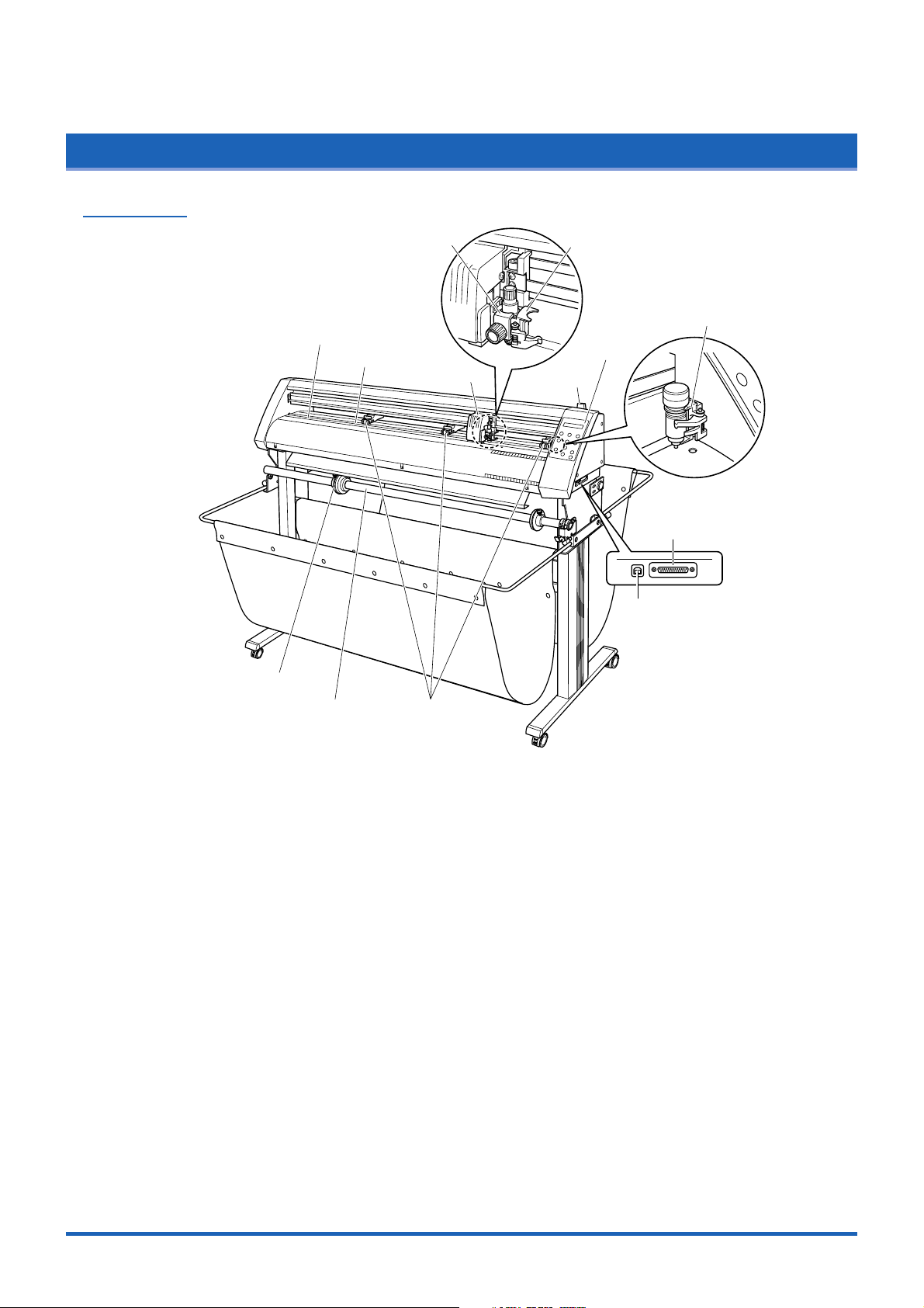
1.2 Parts Names and Functions
Front View
Introduction
Stopper
Cutting mat
Cutter pen holder
Grit roller
Pen carriage
Pen holder
Pen station
Control panel
Media set lever
Serial (RS-232C)
interface connector
USB interface connector
Push rollersStock shaft
Cutting mat.............. Cutting or plotting is performed on this mat.
Grit roller ................. Feeds the medium backward or forward.
Pen carriage ............ Moves the cutter pen to the left and right.
Cutter pen holder.... Hold the cutter pen and moves it up and down.
Pen holder ............... Holds the pen and moves it up and down.
Media set lever ........ Raises or lowers the push rollers during loading of a medium.
Control panel........... Used to operate the cutting plotter and set functions.
Pen station .............. Used to mount the pen before it is used.
Stoppers .................. Used to hold a roll medium in place (left and right, one each).
Stock shaft .............. Used to load roll media.
Push rollers ............. Pushes the medium against the grit rollers.
Serial (RS-232C) interface connector
........................ Used to connect an RS-232C serial interface cable.
USB interface connector
........................ Used to connect a USB cable.
1-3
Page 15

Introduction
Rear View
Power switch
AC power inlet
Stand
Basket
Alignment shaft
Basket ...................... Used to catch media after it has been cut.
Alignment shaft....... Used when loading roll media.
Power switch ........... Turns the power supply to the cutting plotter on or off.
AC power inlet......... Connects the power cord to the cutting plotter.
Stand........................ Supports the cutting-plotter unit.
1-4
Page 16

Control Panel
Introduction
Indicator Lamp
STATUS .......... Illuminates while the power to the cutting plotter is
turned on, and goes out when the cutting plotter is in
PAUSE status. This lamp flashes when data is being
received from an interface, regardless of whether or
not the cutting plotter is in PAUSE status.
Panel Keys
TEST......... Press this function key to conduct a cutting test and
check the cutting conditions.
PREV. ....... Press this function key to view the previous display on
the LCD when in PAUSE status.
NEXT ........ Press this function key to view the next display on the
LCD when in PAUSE status.
COND. ...... Press this function key to view the cutter-pen
condition settings.
PAUSE...... Press this function key once in READY status to
switch to PAUSE status in order to change the various
settings. Press it again to cancel the PAUSE status.
Pressing this key while cutting or plotting is in
progress stops the cutting or plotting.
ENTER...... Pressing this function key registers the cutting or
plotting conditions set.
POSITION
.............. These keys are used to move the cursor or change
the settings on the LCD display on the function setting
screens. Press these keys when in PAUSE status to
move the pen carriage or the medium.
ORIGIN .....Press this function key to set the origin point. The pen
position is set as the origin point when this key is
pressed.
1-5
Page 17

Introduction
1.3 Assembling the Stand
Stand Construction
The stand is made up of the following parts.
Stand side bar x 2 (L/R) Center bar x 1
Alignment shaft x 1
Basket Construction
Hexagonal socket bolt (M6) x 8
Allen wrench (M6) x 1
Stopper x 2 (L/R)
Stock shaft x 1
The basket is made up of the following parts.
Sheet support pipe x 2
Sheet support pipe bracket x 2 Rubber cap x 4 Hexagonal socket bolt (M6) x 4
Sheet x 1
1-6
Page 18

Assembling the Stand
(1) Fasten the center bar to the stand side bars (L/R) temporarily with the hexagonal socket bolts
(M6), using the Allen wrench.
Introduction
Front side
Center bar
Stand side bar
Hexagonal
socket bolt (M6)
(2) Fasten the sheet support pipe brackets to the stand tops with the hexagonal socket bolts (M6).
stand tops
Support pipe bracket
Hexagonal socket bolt (M6)
1-7
Page 19

Introduction
(3) Insert the sheet support pipes into the sheet support pipe brackets. Use the lower holes for the
pipe that will be at the front of the cutting plotter, and the upper holes for the pipe that will be at
the rear.
Remove the tape from the ends of the pipes to expose the adhesive, and then fit the rubber
caps on firmly.
Sheet support pipe
Rubber cap
Removable tape
(4) Mount the CE3000-120AP on the stand by inserting the positioning pins on the stand into the
positioning holes on the underside of the cutting plotter and then fasten with the four
hexagonal bolts (M6).
CE5000AP
cutting plotter
Positioning pin
Stand
Hexagonal
socket bolt (M6)
1-8
Stoppers
CHECKPOINT
Make sure that the casters with the stoppers are at the front.
Page 20

Introduction
(5) Attach the media guide bracket to the underside of the front panel. Loosen the two decorative
screws that are attached to the underside of the front panel (one on each side) by two or three
turns, slot the bracket in, and then tighten the screws.
Pin
Decorative screw
Media guide bracket
CAUTION
• When attaching the media guide bracket, take care not to drop it on your feet or on any other
parts of your body. Make sure that the decorative screws and pins are fitted into the U-shaped
cutouts on the media guide bracket.
• When loosening or tightening the decorative screws, take care not to injure yourself on any parts
in their vicinity.
(6) Attach the alignment shaft to the stand tops. Loosen the attached bindhead screws A (M4) two
or three turns, and then insert the brackets on the end of the shaft using the elongated screw
holes. Remove the fixing tape from the alignment shaft and then push the shaft in until it
contacts the curved area indicated by "a" in the figure below. Tighten the A (M4) bindhead
screws. When the shaft has been attached, tighten the bindhead screws B (M4), and check
that the shaft does not rotate. The bindhead screws B are screws to prevent the shaft from
rotating. Tighten the screws so that the holes in the shaft are positioned approximately in the
center in the horizontal direction and at the top and bottom in the rotation direction.
a
a
stand top
a
Alignment shaft
stand top
Bracket
Bindhead screws A (M4)Bindhead screws B (M4)Fixing tape
1-9
Page 21

Introduction
(7) Tighten all the hexagonal bolts that were temporarily fastened in step 1.
(8) Pull out the sheet support pipes, and attach the sheet to them. Pass the sheet over the center
bar, and fasten the ends to the support pipes using the press-studs.
Sheet support pipe
Press-stud
Pass over the center bar
Side view
Sheet
Sheet
center bar
(9) Attach the stoppers (L/R) to the stock shaft and then attach the shaft to the top of the stand.
Stopper
Stock shaft
Collar
1-10
Page 22

CHAPTER 2
Setting up The Cutter Plotter
2.1 Connecting to Your Computer
2.2 Turning on the Power
2.3 Loading the Medium
2.4 If the sensor detects that there is no paper
left while roll paper is being cut
2.5 Adjusting and Mounting the Cutter Pen
2.6 Mounting the Pen
Page 23

Setting up The Cutter Plotter
2.1 Connecting to Your Computer
The cutting plotter can be connected to a computer via the serial (RS-232C) port or USB port. Select which
port to use according to the requirements of your application software and/or which of your computer's
interface ports are available for use.
Use a Centronics-compatible serial cable or USB cable in accordance with the connection method chosen.
Obtain a Graphtec approved interface cable that is compatible with the interface ports (the interface cables
are available separately).
(1) Check to confirm that the Power switch is turned off (the "O" side is down).
(2) Connect the cable between the cutting plotter and the computer. Make sure the connectors at
the cutting plotter and computer ends are correctly oriented.
2-2
Page 24

Setting up The Cutter Plotter
2.2 Turning on the Power
Connect the cutting plotter to the AC electrical socket using the power cord provided, and turn on the power.
(1) Check to confirm that the Power switch is turned off (the "O" side is down).
(2) Connect the cutting-plotter AC power inlet to a correctly rated electrical socket using the power
cord provided.
(3) Turn on the cutting plotter by pressing the "|" side of the Power switch. The STATUS lamp on
the control panel will light up.
(4) If no medium has been loaded, the message below appears on the display, prompting the
loading of a medium.
LOAD MEDIA!!
If a medium has already been loaded, the current media setting is displayed as shown below.
ROLL1 PRESS ENTR
Select the media mode to suit the medium used. For instructions on loading media and
selecting the media mode, see "2.3 Loading the Medium."
2-3
Page 25

Setting up The Cutter Plotter
2.3 Loading the Medium
Load the medium, aligning it with the right-hand grit roller when viewed from the front so that it registers with
the media sensor. Then, adjust the push-roller position to match the width of the medium. The cutting plotter
can use media in roll or sheet form. Load the desired medium type by following the appropriate instructions.
Loading a Roll Medium
Load the roll medium onto the stock shaft on the stand.
(1) Confirm that the roll is correctly oriented, and then slide the stoppers onto the shaft.
Stopper
Stock shaft
Stopper
Stopper screw
Position the stoppers at the appropriate locations and then tighten the screws. At this time, if
you have loaded a 950-mm media roll, fix the stoppers at the positions shown in the following
diagrams. If the media roll is of a different width, loosen the stopper screws, align the roll with
the plotter’s grit roller positions, and then tighten the stopper screws.
Medium
Mount the collar so that its side with
the smaller diameter contacts the white
plastic part of the shaft holder.
For 2-inch diameter cores
Stopper screw
Approx. 20 mm
Collar
Stock shaftStopper
Medium
For 3-inch diameter cores
Stopper screw
Stock shaftStopper
Approx. 32 mm
Mount the collar so that its side with
the smaller diameter contacts the white
plastic part of the shaft holder.
Collar
2-4
(2) Mount the stock shaft at the front of the cutting plotter.
Page 26

Setting up The Cutter Plotter
Align the collar with the shaft holder, and then press down firmly on the collar until it is fully
seated.
Press down firmly
on the collar
Stock shaft
CollarShaft holder
CAUTION
• While cutting or plotting is in progress,
please keep your hands, hair, etc., away
from the shaft holder and the collar.
• Performing a cutting or plotting operation
when the stock shaft is seated at an angle
may cause malfunctions such as paper
shift to occur.
Confirm that the roll is correctly oriented.
OK
NG
(3) If you have not already done so, align the stoppers with the left and right edges of the roll
medium and then tighten the stopper screws.
(4) Lower the media set lever to raise the push rollers.
2-5
Page 27

Setting up The Cutter Plotter
(5) Move the stock shaft stopper to the FREE position.
FREE position:
This is the status when the lever has been pushed down and engaged, and the silver-colored
section is hidden. The stock shaft rotates in the FREE status.
LOCKFREE
Black sticker Silver-colored section
CAUTION
While cutting or plotting is in
progress, please keep your
hands, hair, etc., away from
the shaft holder and the collar.
(6) Feed the leading edge from the back through to the front, making sure to remove any slack in
the medium while pulling it towards you.
Media sensor
2-6
CHECKPOINT
Load the medium so that it passes over the media sensor.
Pass the medium's leading edge over the center bar and around the outside of the alignment
shaft.
OK
(7) Adjust the position of the left- and right-hand push rollers to suit the width of the medium.
(See "Aligning the Push Rollers" later in this section.)
NG NG
Page 28

Setting up The Cutter Plotter
A
B
(8) Move the stock shaft stopper to the LOCK position.
LOCK position:
This is the status when the lever has been pulled up and inserted into the groove, and the
silver-colored section can be seen. The stock shaft does not rotate in the LOCK status.
LOCKFREE
Black sticker Silver-colored section
CAUTION
While cutting or plotting is in
progress, please keep your
hands, hair, etc., away from
the shaft holder and the collar.
(9) When pulling the medium out of the cutting plotter, stand facing the front of the cutting plotter
and pull the center point of the medium's width toward you.
OK
NG NG
(10) As shown in the figure below, pull on the medium at the front of the cutting plotter, so that the
medium's tension is equal at areas A and B.
(11) After confirming that the medium's tension is equal at both sides, raise the media set lever to
lower the push rollers and hold the medium in place.
2-7
Page 29

Setting up The Cutter Plotter
(12) Move the stock shaft stopper to the FREE position.
FREE position:
This is the status when the lever has been pushed down and engaged, and the silver-colored
section is hidden. The stock shaft rotates in the FREE status.
LOCKFREE
Black sticker Silver-colored section
CAUTION
While cutting or plotting is in
progress, please keep your
hands, hair, etc., away from
the shaft holder and the collar.
(13) Raising the media set lever displays a menu for selection of the media mode. Select the media
mode.
ROLL1 PRESS ENTR
CHECKPOINT
If the "REALIGN ROLLERS" message is displayed when the medium is detected, either the righthand push roller is not positioned over the right-hand wide grit roller or the left-hand or center
push roller is not positioned over a grit roller. Check to confirm that they are positioned correctly.
(14) Pressing the or key displays "ROLL1 PRESS ENTR" and "ROLL2 PRESS ENTR".
Select "ROLL1 PRESS ENTR" or "ROLL2 PRESS ENTR", and then press the (ENTER)
key to confirm.
When "ROLL1 PRESS ENTR" is selected, the leading edge and width of the medium are
detected. Select this mode to begin cutting from the leading edge.
When "ROLL2 PRESS ENTR" is selected, only the medium width is detected. Select this
mode to begin cutting at a point beyond the leading edge.
(15) After "ROLL1 PRESS ENTR" or "ROLL2 PRESS ENTR" has been selected, the following
message is displayed.
UNLOCK MEDIA PRESS ENTER KEY
Displayed alternately
Move the stopper to the FREE position and then press the (ENTER) key.
(16) After the medium size has been detected, the pen carriage returns to the origin point and the
cutting plotter awaits cutting data. If the INTERFACE conditions or COMMAND mode have not
yet been set, they should be set. If they have already been set, adjust the cutter pen. Once the
cutter pen has been adjusted, the cutting plotter is ready to perform cutting, so cutting data can
be sent from the application software on the computer.
Precautions when using roll paper
If there is a problem with the paper feed and the paper is not being fed correctly into the basket,
open the media basket out to its maximum size and lower the speed.
CHECKPOINT
Be sure to remove media on which the cutting or plotting operation has been completed from the media
basket. If media is left in the basket while the next cutting or plotting operation is being performed,
paper shift or other malfunctions may occur.
2-8
Page 30

Loading a Sheet Media
(1) Lower the media set lever to raise the push rollers.
(2) Load the medium, aligning the edges with the upper and lower scales on the front guide.
Setting up The Cutter Plotter
Media sensor
Align with scale
CHECKPOINT
Load the medium so that it passes over the media sensor.
(3) Adjust the position of the left- and right-hand push rollers to suit the medium width.
(4) Raising the media set lever displays a menu for selecting the media mode. Select the media
mode.
SHEET PRESS ENTR
CHECKPOINT
If the "REALIGN ROLLERS" message is displayed when the medium is detected, either the righthand push roller is not positioned over the right-hand wide grit roller or the left-hand or center
push roller is not positioned over a grit roller. Check to confirm that they are positioned correctly.
(5) Pressing the or key displays "ROLL1 PRESS ENTR", "ROLL2 PRESS ENTR", and
"SHEET PRESS ENTR". Select "SHEET PRESS ENTR" and then press the (ENTER) key
to confirm the selection. When "SHEET PRESS ENTR" is selected, the front and rear edges
are detected.
(6) After the medium size has been detected, the pen carriage returns to the origin point and the
cutting plotter awaits cutting data. If the INTERFACE conditions or COMMAND mode have not
yet been set, they should be set. If they have already been set, adjust the cutter pen. Once the
cutter pen has been adjusted, the cutting plotter is ready to perform cutting, so cutting data can
be sent from the application software on the computer.
2-9
Page 31

Setting up The Cutter Plotter
Aligning the Push Rollers
Adjust the position of the left- and right-hand push rollers to suit the medium width. Position the
push rollers at either edge of the medium so that they are above the grit rollers. Adjust the push
rollers so that they are positioned above both the medium and the grit rollers. Positioning the push
rollers within the push-roller alignment marks ensures that they are above the grit rollers.
Push-roller alignment mark
NG
OK
NG
OK
CAUTION
To move the push rollers, the media set lever must be in the lowered position.
The push roller on the right-hand edge when viewed from the front must always be moved over the
right-hand wide grit roller.
Right-hand push roller
Right-hand grit roller
2-10
Media sensor
CAUTION
To move the push rollers, the media set lever must be in the lowered position.
CHECKPOINT
If the "REALIGN ROLLERS" message is displayed when the medium is detected, either the right-hand
push roller is not positioned over the right-hand wide grit roller or the left-hand or center push roller is
not positioned over a grit roller. Check to confirm that they are positioned correctly.
Page 32
Setting up The Cutter Plotter
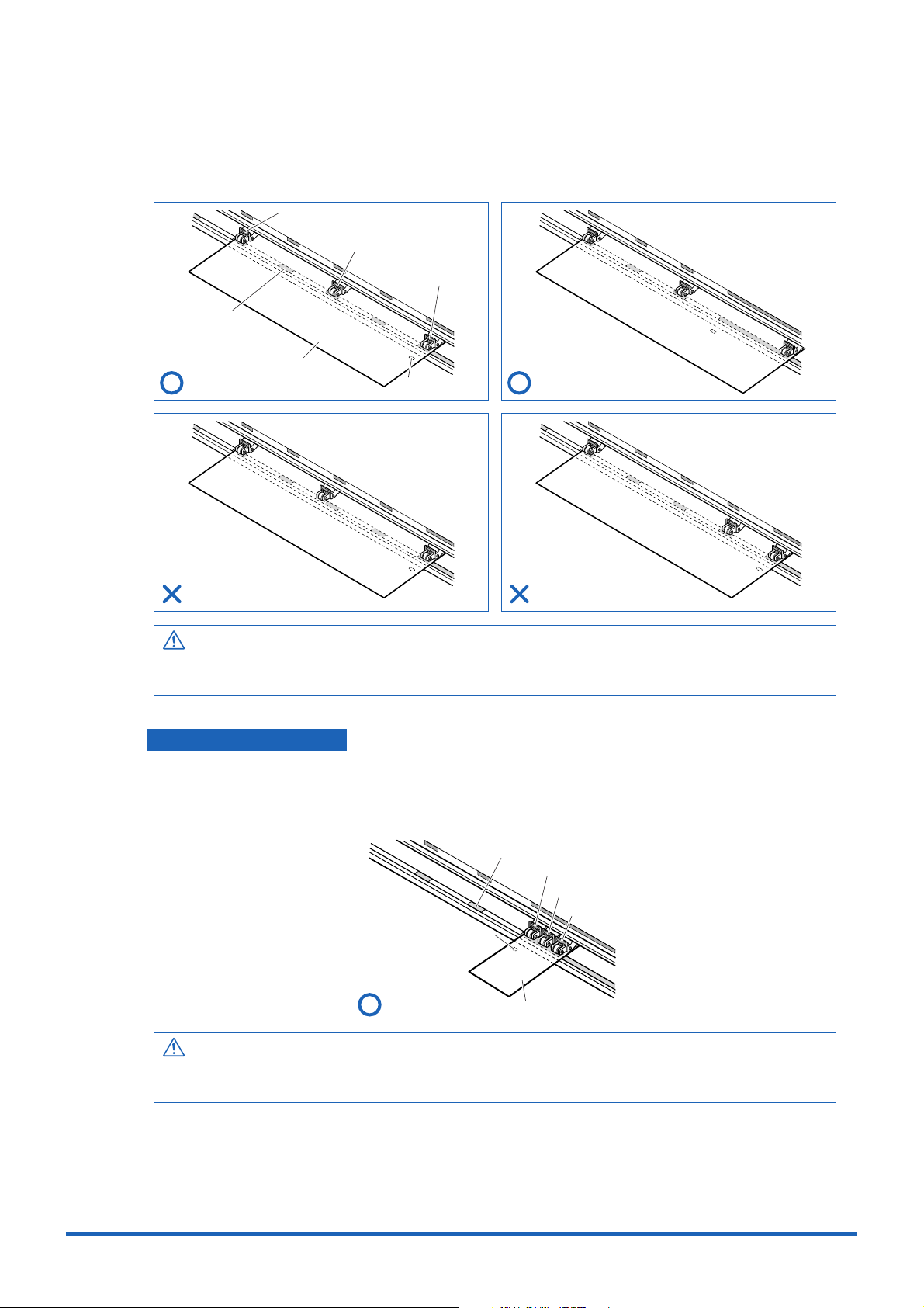
Position push rollers (1) and (3) over the grit rollers to grip each edge of the medium, and position
push roller (2) over the grit roller nearest the center of the medium. The medium is gripped by the
three push rollers (1), (2), and (3).
Push roller (3)
Push roller (2)
Push roller (1)
Grit roller
Media
OK
Media sensor
OK
NG
NG
CAUTION
• Push roller (1) must be positioned over the right-hand wide grit roller.
• The medium must always be positioned over the media sensor.
For Minimum-Size Media
Position all of the rollers over the right-hand wide grit roller. Position the medium with the left-hand
edge aligned with the left-hand edge of the grit roller, and position the push rollers over both edges.
The minimum width of the medium that can be set is 85 mm.
Grit roller
Push roller (3)
Push roller (2)
Push roller (1)
Media sensor
OK
Media
CAUTION
• The medium must be at least 125 mm in length.
• The medium must always be positioned over the media sensor.
2-11
Page 33

Setting up The Cutter Plotter
2.4
If the media sensor detects that there is no paper left during a roll paper cutting operation, cutting is stopped
automatically. Check the length of paper remaining, and select whether to continue or abort the cutting
operation.
If the sensor detects that there is no paper left while roll paper is being cut
(1) If the media sensor detects that there is no paper left during a roll paper cutting operation,
cutting is stopped automatically and the following message is displayed.
No Media
(2) If the (ENTER) key is pressed, plotting/cutting is continued and subsequent paper end
detection is not performed. Moreover, if the media set lever is lowered and a media feed
operation performed, paper end detection will be performed once again.
2-12
Page 34
Setting up The Cutter Plotter
2.5 Adjusting and Mounting the Cutter Pen
Individual cutter blades have a variety of features. Select the optimal cutter blade to suit the medium to be
cut.
CAUTION
To avoid cutting your fingers, always handle the cutter blade with caution.
Types and Features of Cutter Blades
Part No. and
profile
CB 09UA
CB 15U
CB 15UB
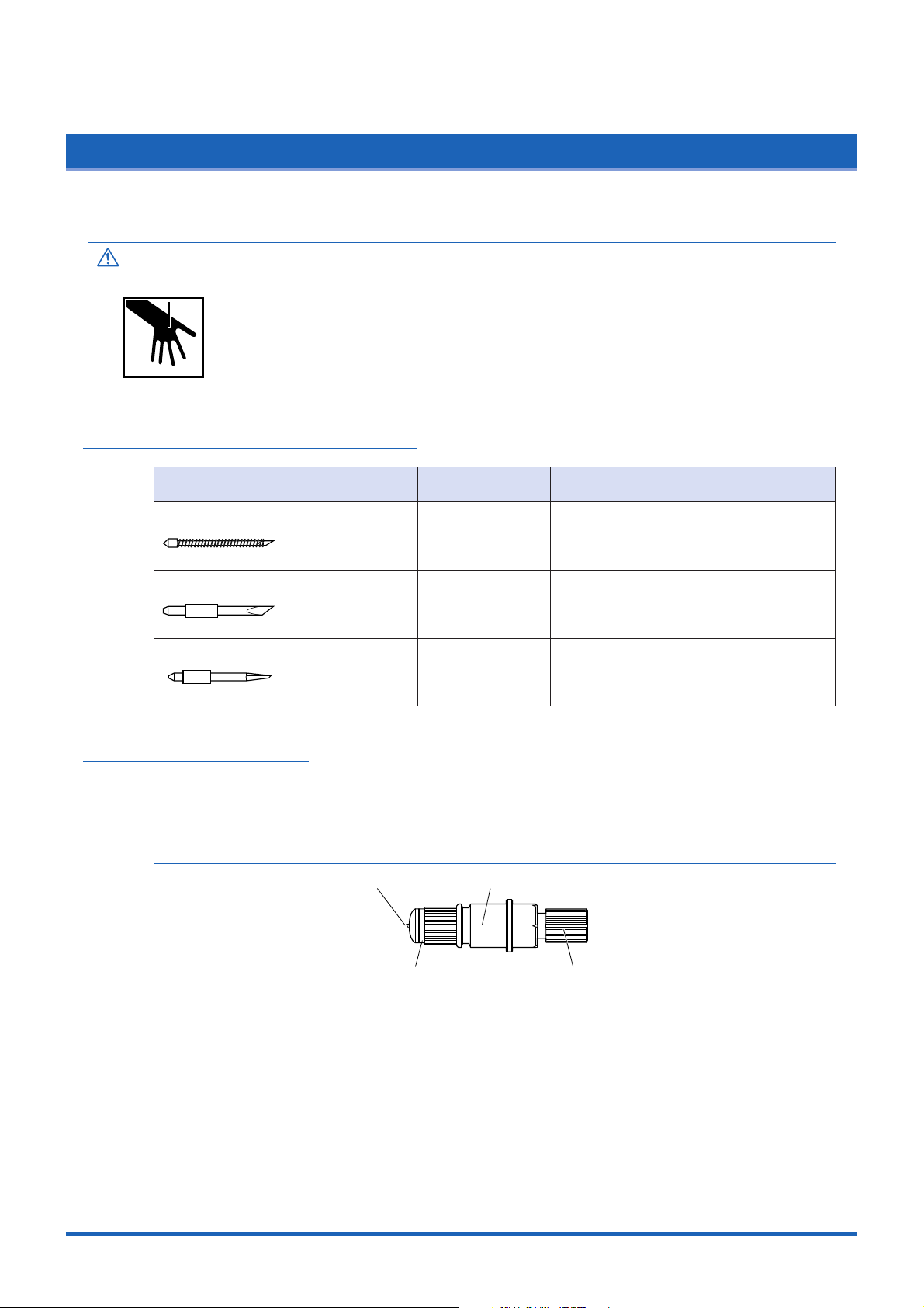
Cutter Pen Construction
The cutting plotter cuts using a cutter blade mounted in a cutter-pen plunger. There are two
different cutter-pen plungers to suit the diameter of the cutter blade to be mounted (the 0.9-mm
cutter-pen plunger is provided as standard equipment). Be sure to mount the cutter blade in the
corresponding cutter-pen plunger.
Blade diameter
and offset
ø0.9 mm
0.45
ø1.5 mm
ø0.75
ø1.5 mm
0.15
Cutter blade
Compatible
plunger
PHP32-CB09N
PHP32-CB15N
PHP32-CB15N
Plunger
Use and features
The standard blade for cutting color
adhesive-backed media. Suitable for
cutting media up to 0.25 mm in thickness.
Max. cutting distance: Approx. 4,000 m
Capable of cutting thicker media than
possible with the CB09UA blade. Suitable
for cutting media 0.25 mm to 0.5 mm in
thickness.
Suitable for detailed cutting (e.g., letters
less than 10 mm in size) of media up to
0.25 mm in thickness.
Plunger cap
Blade-length adjustment knob
(Blue: For 0.9-mm-diameter blades)
(Red: For 1.5-mm-diameter blades)
2-13
Page 35

Setting up The Cutter Plotter
Replacing the Cutter Blade
CAUTION
To prevent cutting your fingers, always handle the cutter blade with caution.
1.5-mm-diameter cutter pen
adjustment knob (red)
Plunger
Plunger-cap
cross-section
adjustment knob (blue)
1.5-mm-dia. blades
Plunger cap
0.9-mm-diameter cutter pen
Plunger
0.9-mm-dia. blades
Spring
Plunger cap
Plunger-cap
cross-section
(1) Turn the blade-length adjustment knob to retract the blade into the plunger.
(2) Turn the plunger cap in the counter-clockwise direction to remove it from the plunger.
(3) Remove the blade from inside the plunger cap.
(4) Insert the new blade into the hole provided in the plunger cap.
(5) With the blade inserted into the plunger cap, screw on the plunger from above.
Adjusting the Blade Length
If the blade is extended too far in relation to the thickness of the medium being cut, it will damage
the cutting mat. Be sure to adjust the blade length correctly.
CAUTION
To prevent cutting your fingers, always handle the cutter blade with caution.
(1) Adjust the blade length by turning the blade-length adjustment knob. Turn the knob in direction
"A" to extend the blade, or in direction "B" to retract the blade. When the knob is turned by
one scale unit, the blade moves approximately 0.1 mm. One full turn of the knob moves the
blade approximately 0.5 mm.
AB
2-14
Page 36

(2) First align the blade tip with the tip of the cutter pen, and then extend the blade from that
position to suit the thickness of the media to be cut.
(3) As a guideline for determining the proper blade length, run a test cut (for instructions, see
Section 3.7 "Test Cutting" and check that the medium is cut. In cases where the medium's
thickness cannot be accurately determined, adjust the blade length by gradually increasing the
blade length as you alternately run a test cut to check whether or not the medium can be cut.
Mounting the Cutter Pen
After the blade length has been adjusted, mount the cutter pen in the cutting plotter.
CAUTION
To prevent cutting your fingers, always handle the cutter blade with caution.
(1) Loosen the pen-holder screw and then mount the cutter pen. While pressing the pen holder
upward, press the cutter pen plunger fully into the pen holder.
Setting up The Cutter Plotter
(2) Once the cutter pen is properly positioned, tighten the pen-holder screw.
Pen mounting bracket
Cutter pen's flange
2-15
Page 37

Setting up The Cutter Plotter
2.6 Mounting the Pen
Mount a pen in the pen station
CHECKPOINT
When mounting a pen for this cutting plotter, be sure to mount it at the pen station. To avoid injury, avoid touching
the pen immediately after the cutting plotter is turned on or whenever the pen is moving.
Open the holder arm of the pen station with your finger, then mount the pen in the pen holder.After
the pen is properly mounted, close the holder arm to secure the pen.
Holder arm
CHECKPOINT
Make sure that the pen's groove fits into the top section of the pen station's bracket.
Be sure to fit into
the pen's groove
2-16
Page 38

CHAPTER 3
Basic Settings and Operations
3.1 Setting the Cutter-Pen Conditions
3.2 Displaying the Effective Cutting Area
3.3 Moving the Pen
3.4 Setting the Initial Cutting Position (Origin Point)
3.5 Stop Function
3.6 Moving the Pen Carriage in +100 mm Steps
3.7 Test Cutting
Page 39

Basic Settings and Operations
3.1 Setting the Cutter-Pen Conditions
Before starting cutting, set the TOOL (cutter blade or pen), cutter-blade length, OFFSET, FORCE, SPEED,
and QUALITY settings to ensure the optimal cutting conditions.
TOOL (cutter blade or pen)
........................ Set to suit the material to be cut.
Cutter-blade length ... Adjust the blade length by referring to the media thickness table below. For
details on adjusting the blade length, see "2.4 Adjusting and Mounting the
Cutter Pen."
OFFSET.................... Set to suit the cutter blade being used.
FORCE ..................... Set the FORCE by referring to the table below.
SPEED...................... Set the SPEED by referring to the table below.
QUALITY................... Set the QUALITY by referring to the table below.
Optimal Cutting Conditions for Each Media Type
Medium thickness Blade used FORCE SPEED QUALITY
approx. 130 g/m
approx. 80 g/m
approx. 65 g/m
2
2
2
CB09UA 14 to 20 30 or less 2
CB09UA 10 to 14 30 or less 2
CB09UA 8 to 12 30 or less 2
Reference force values (FORCE = g)
Setting FORCE Setting FORCE Setting FORCE Setting FORCE
120 94017 96 25 200
221104318104 26 218
322114819112 27 234
424125620120 28 250
527136421136 29 267
630147222153 30 284
733158023170 31 300
837168824185
Blade Part Nos., Displayed Blade Types, and Displayed CUTTER OFFSET Values
Blade material Part No.
Supersteel blades CB09UA 09U 0 ±518
CB15U 15U 0 ±528
CB15UB 15B 0 ±55
Pens PEN – – 0
LCD display indication
Blade type Default CUTTER OFFSET
Specifiable range
Initial
When the TOOL (cutter blade or pen) has been selected from among "09U," "15U," and "15B,"
the OFFSET is automatically adjusted by ±5 with respect to the default cutter offset value for that
blade type. Select the PEN setting for plotting using a pen. When the PEN setting is selected, no
OFFSET setting is required.
Reference Pen Conditions for Plotting Pens
Pen type FORCE SPEED QUALITY
Water-based fiber-tip pen 10 to 12 30 2
3-2
To preserve the pen life, set the FORCE to the lowest setting, and set the SPEED after checking to
confirm that there are no faint lines or other problems during plotting.
CHECKPOINT
• If the SPEED and QUALITY settings are set to high values, the cut/plotted results will have a coarser
finish, but the overall cutting/plotting time will be reduced.
• If the SPEED and QUALITY settings are set to low values, the cut/plotted results will have a finer
finish, but the overall cutting/plotting time will be longer.
Page 40

Storing and Selecting Cutter Pen Condition Setting Areas
Eight different sets of user-defined cutting conditions can be registered in the plotter's memory as
COND Nos. 1 through 8. To specify a set of cutting conditions, you must first select the destination
COND. No. By selecting a different COND No., you can easily switch between pre-defined cutting
conditions for eight sets of media.
CHECKPOINT
The pen number settings for the CE5000-120AP are as follows. These settings cannot be changed.
Basic Settings and Operations
Command-specified
pen number
1
2
3
4
8
COND. No.
1
2
3
4
8
Physical
pen number
1
(Pen holder)
2
(Cutter pen holder)
Storage method
Press the (COND.) key in READY mode to display the cutter-pen conditions.
2 09U +1 23 30 2
The current settings are displayed (from the left): condition number, PEN TYPE (cutter blade),
CUTTER OFFSET, FORCE, SPEED, and QUALITY.
The item to be changed is indicated by the t symbol. Press the key to change the symbol to
s, and press again to move it to the right. Press the key to move it to the left. Use the or
key to select the parameter to be changed, and use the or key to select the setting
details. Press the (ENTER) key to confirm. To cancel the selection, press the (NEXT),
(PREV.), or (COND.) key.
Selection method
To select condition settings that have already been stored, select the condition number to which
those conditions have been stored on the cutter-pen-condition settings display and then press the
(ENTER) key.
If Tangential mode (see "4.7 Setting the TANGENTIAL Mode") or distance adjustment (see "4.12
Distance Adjustment") has been specified for a condition number, the cutting plotter will display
the tangential mode or distance adjustment setting menu after the above setting has been made.
Setting TOOL (cutter blade or pen)
Set the type of pen (cutter blade) to be used.
(1) Press the (COND.) key in READY mode to display the cutter-pen conditions.
(2) Select the setting area (condition number) to be set, and then press the or key to move
the s symbol to the position shown below.
2 09U +1 23 30 2
(3) Press the or key to select "09U," "15U," "15B," or "PEN." Press the (ENTER) key
to confirm the selection. If other conditions are to be set, press the or key to move the
s symbol to the parameter to be set.
3-3
Page 41

Basic Settings and Operations
Setting OFFSET
This setting adjusts the offset of the cutter blade to suit the blade type used. The tip of the blade
mounted in the cutter-pen plunger is not positioned at the center of the pen, so correction is
required. This correction is referred to as the OFFSET setting. The cutting plotter has been preset
with OFFSET values for each cutter-blade type. Selecting "09U," "15U," or "15B" for the PEN
TYPE setting also sets the appropriate OFFSET, allowing fine adjustment within the range of ±5.
When the "PEN" setting is selected, the OFFSET cannot be set.
(1) Press the (COND.) key in READY mode to display the cutter-pen conditions.
(2) Select the setting area (condition number) to be set, and then use the or key to move
the s symbol to the position shown below.
2 09U +1 23 30 2
(3) Use the or key to select the value to be changed in the range of "-5" to "+5." Press the
(ENTER) key to confirm the selection. If other conditions are to be set, press the or
key to move the symbol to the parameter to be set.
Setting FORCE
Sets the pressure applied by the cutter pen during cutting. Set the FORCE value based on the
guidelines in the table entitled "Optimal Cutting Conditions for Each Media Type" on page 3-2.
(1) Press the (COND.) key in READY mode to display the cutter-pen conditions.
(2) Select the setting area (condition number) to be set, and then use the or key to move
the s symbol to the position shown below.
2 09U +1 23 30 2
(3) Press the or key to select the value to be changed in the range specified below.
"1" to "31"
Press the (ENTER) key to confirm the selection. If other conditions are to be set, press the
or key to move the s symbol to the parameter to be set.
Setting SPEED
Sets the speed used for cutting. Set the SPEED value based on the guidelines in the table entitled
"Optimal Cutting Conditions for Each Media Type" on page 3-2.
(1) Press the (COND.) key in READY mode to display the cutter-pen conditions.
(2) Select the setting area (condition number) to be set, and then use the or key to move
the s symbol to the position shown below.
3-4
2 09U +1 23 30 2
(3) Press the or key to select the value to be corrected in the range specified below.
"1" to "60"
All models: In increments of 1 for "1" to "10", and in increments of 5 for "10" to "60".
Press the (ENTER) key to confirm the selection. If other conditions are to be set, press the
or key to move the s symbol to the parameter to be set.
Page 42

Setting QUALITY
Sets the acceleration used in cutting.
(1) Press the (COND.) key in READY mode to display the cutter-pen conditions.
(2) Select the setting area (condition number) to be set, and then use the or key to move
the s symbol to the position shown below.
2 09U +1 23 30 2
(3) Press the or key to select the value to be changed in the range specified below
"1", "2"
Press the (ENTER) key to confirm the selection. If other conditions are to be set, press the
or key to move the s symbol to the parameter to be set.
Basic Settings and Operations
3-5
Page 43

Basic Settings and Operations
3.2 Displaying the Effective Cutting Area
Press the (ENTER) key in READY mode to display the current effective cutting area.
X 0000mm Y 000mm
3.3 Moving the Pen
In READY mode, press the or key to move the pen carriage to the left or right, and the or key
to feed the medium backward or forward.
3-6
Page 44

Basic Settings and Operations
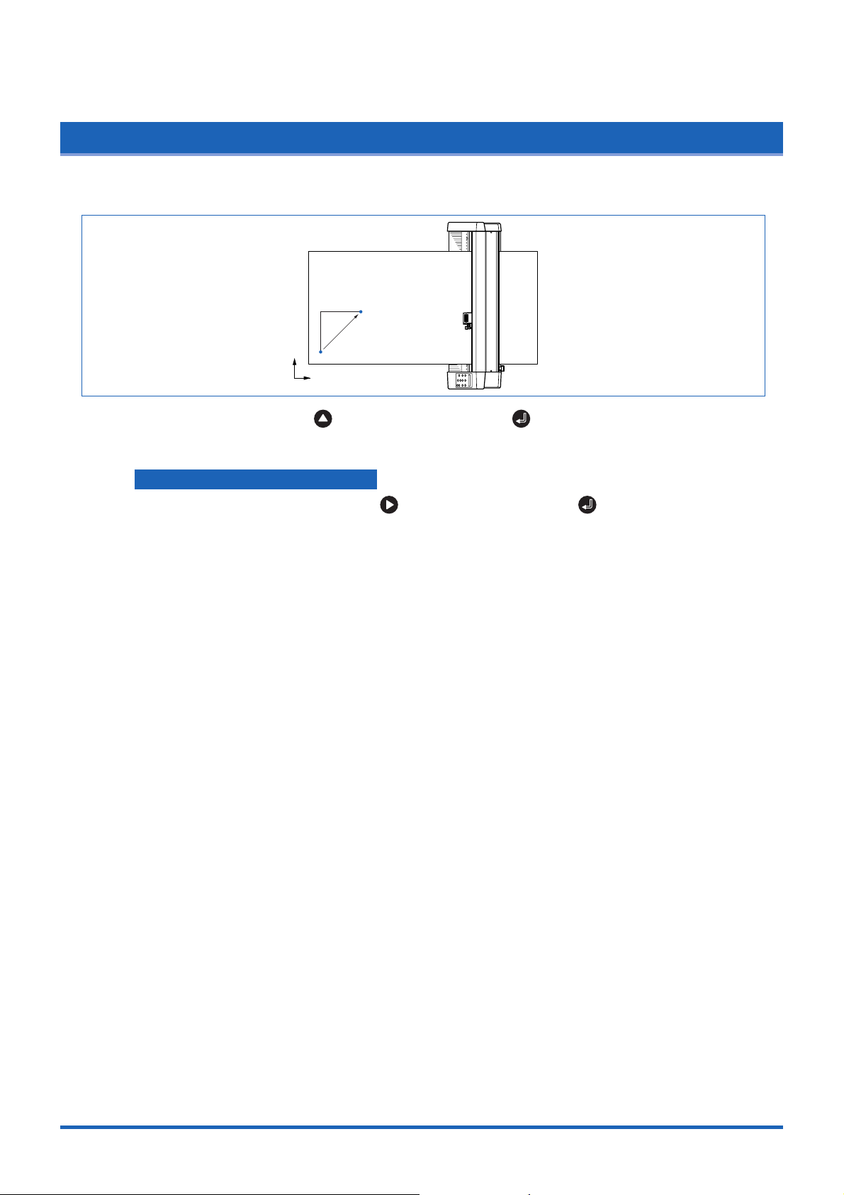
3.4 Setting the Initial Cutting Position (Origin Point)
This function allows the starting position for cutting or plotting to be moved to the desired position.
New origin
Y
Original origin
X
(1) In READY mode, use the , , and (POSITION) keys to move the cutter pen to the
new origin point.
(2) Press the (ORIGIN) key. The following menu is displayed and the new origin is set.
ORIGIN PT SET
When the Origin is Moved After Rotating the Coordinate Axes
Moving the origin when the coordinate axes have been rotated gives the following results.
Y
Original origin
X
New origin
When the Coordinate Axes are Rotated After Moving the Origin Point
When the coordinate axes are rotated after the origin point is moved, the origin point is reset as
shown in the figure below. The distance "a" is retained, but the distance "b" is reset.
Y
X
Origin moved
after rotation
a
a
Y
Original origin
X
b
Origin moved
b
Original origin
Origin moved
Origin moved Rotation
When it is necessary to both move the origin and rotate the coordinate axes, be sure to rotate the
coordinate axes first.
CHECKPOINT
After a new origin point is set, the displayed coordinate values of X= and Y= represent the respective
distances from the new origin.
3-7
Page 45
Basic Settings and Operations
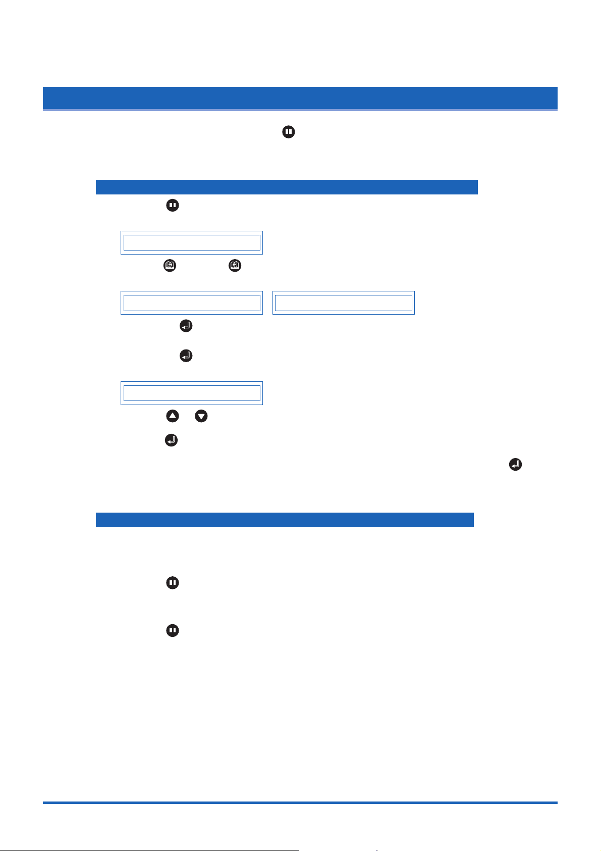
3.5 Stop Function
Cutting or plotting can be stopped by pressing the (PAUSE) key while cutting or plotting is in progress.
Raising or lowering the media set lever while cutting or plotting is stopped does not require the medium to be
selected, and so the medium can be replaced or reset.
If "PAUSE" has been specified at the "PAUSE key" Special Functions menu
(1) Press the (PAUSE) key while cutting or plotting is in progress to stop cutting or plotting and
display the PAUSE menu.
CONTINUE JOB
(2) Press he (NEXT) or (PREV.) key to alternate the display between "CONTINUE JOB"
and "QUIT JOB".
CONTINUE JOB QUIT JOB
(3) Pressing the (ENTER) key while "CONTINUE JOB" is displayed cancels the pause
function and restarts cutting or plotting.
(4) Pressing the (ENTER) key while "QUIT JOB" is displayed displays the BUFFER CLEAR
confirmation screen for aborting the cutting/plotting operation.
CLEAR <YES>
(5) Press the or key to alternate the display between "YES" or "NO". To abort the cutting/
plotting operation, stop the transmission of data from the computer, select "YES", and then
press the (ENTER) key. All the cutting/plotting data stored in the buffer is cleared and the
plotter returns to Ready status.
To cancel the aborting of the cutting/plotting operation, select "NO" and then press the
(ENTER) key.
The plotter returns to the "CONTINUE JOB" display.
If "MENU" has been specified at the "PAUSE key" Special Functions menu
Note: This setting is the factory default setting
The PAUSE menu is displayed after operation has been stopped to enable the various settings to
be changed.
(1) Press the (PAUSE) key while cutting or plotting is in progress to stop cutting or plotting and
display the following menu.
(2) Change the PAUSE menu settings.
(3) Press the (PAUSE) key to cancel the PAUSE status and restart cutting or plotting.
3-8
Page 46
Basic Settings and Operations
3.6 Moving the Pen Carriage in +100 mm Steps
This function allows the pen carriage to be moved from its current position in +100 mm steps along the Xand Y -ax es.
100mm
Moved pen-carriage
position
100mm
Y
Original pen-carriage position
X
In READY mode, press the key while holding down the (ENTER) key to move the pen
carriage in +100 mm steps along the X- and Y-axes.
Returning to the original position
In READY or PAUSE mode, press the key while holding down the (ENTER) key to return
the pen carriage to the origin.
3-9
Page 47
Basic Settings and Operations
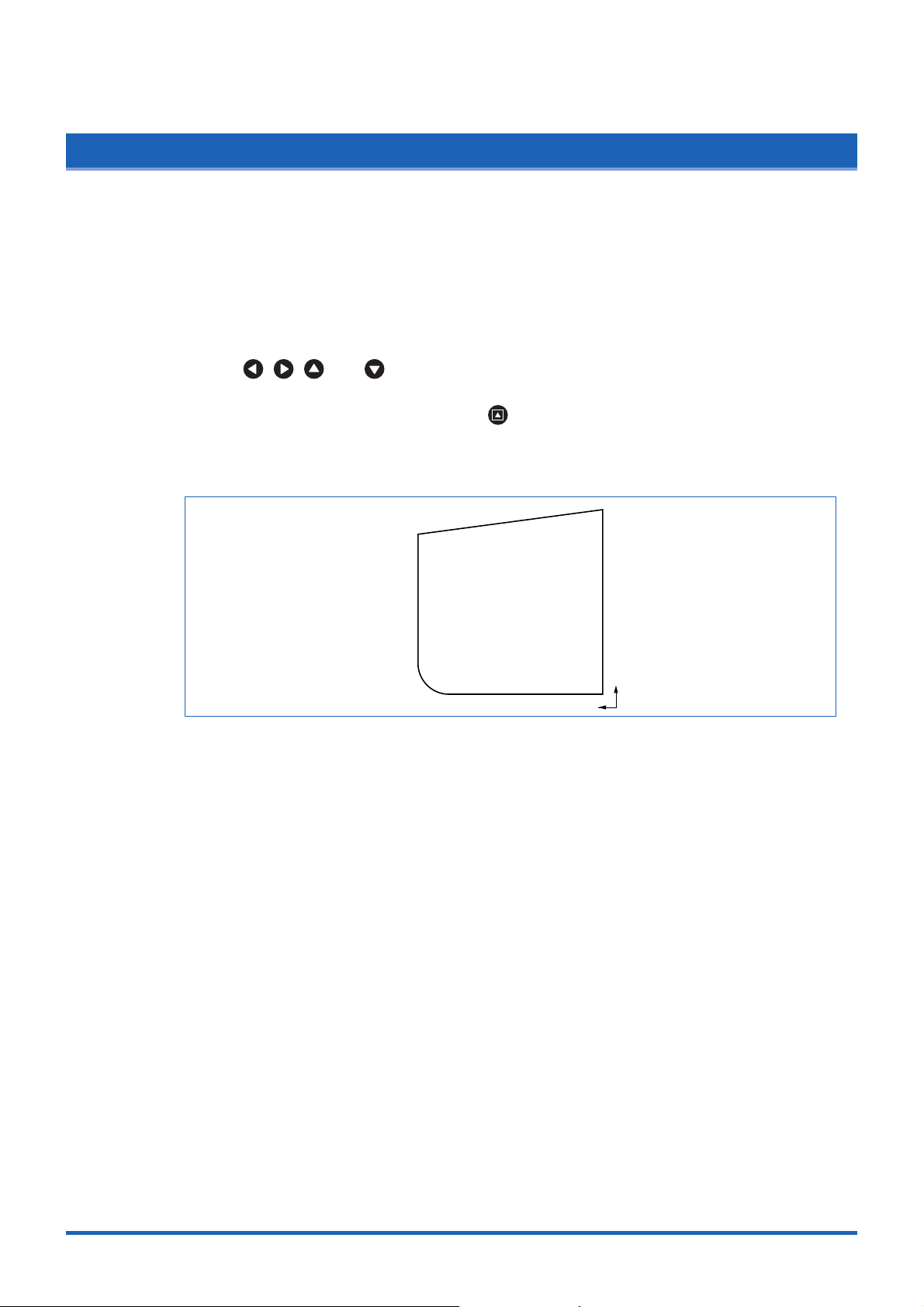
3.7 Test Cutting
Test cutting can be performed after selecting the TOOL (cutter blade) and specifying the cutter-blade length,
OFFSET, FORCE, SPEED, and QUALITY settings to ensure that the selected cutting conditions actually
produce the desired cutting results. Check how far the blade cuts into the medium and how corners are being
cut; if the cutting results are not satisfactory, reset the cutting conditions and repeat the test cutting until the
optimal settings are achieved. If you perform test cutting while the cutter-pen conditions are being set, the
test cutting will be performed under the conditions being set.
(1) Load the medium for test cutting on the cutting plotter.
(2) Use the , , , and (POSITION) keys to move the pen carriage to the position for
test cutting.
(3) Switch to READY mode, and then press the (TEST) key.
(4) Adjust the CUTTER OFFSET value to suit the type and thickness of the medium being used,
and fine-adjust the finish of each corner. Adjust the FORCE setting so that the medium is cut
through completely when the blade is extended to a suitable length.
X
Y
(5) Upon completion of fine adjustment, actual cutting data can be sent to the cutting plotter.
3-10
Page 48

CHAPTER 4
Function Settings and Operations
4.1 PAUSE Menu List
4.2 Clearing the Buffer Memory
4.3 Setting the FEED & CUT function
4.4 Blade Wear Detection (When Blade Wear Setup is On)
4.5 Raising and Lowering the Pen
4.6 Selecting the Type of Perforated Line
4.7 Setting T ANGENTIAL Mode
4.8 Selecting the Blade Tip's Initial Position
4.9 Setting the PEN UP SPEED
4.10 Specifying the INITIAL FEED Length
4.11 Setting AUTO PRE-FEED
4.12 Distance Adjustment
4.13 Aligning the Coordinate Axes
4.14 Setting the Cutting/Plotting Area
4.15 Expanding the Cutting/Plotting Area
4.16 Rotating the Coordinate Axes
4.17 Sorting Settings
4.18 Specifying the SPACE REAR Distance
4.19 Setting the OFFSET FORCE (Initial Cutting Force)
4.20 Setting the Initial Down Force
4.21 Setting the STEP PASS
4.22 Setting the OFFSET ANGLE
4.23 Setting the F_CUT Function
4.24 Setting the LENGTH UNIT
4.25 Adjusting the Distance Between the Pens
4.26 Cutting/Plotting Using the Buffer Memory (COPY Function)
4.27 User-specified Settings
4.28 Setting the Format of Data to be Received
4.29 Interface Settings
4.30 Setting the PAGE LENGTH
4.31 Setting the SEPARATOR Function
4.32 Setting the TIMEOUT Function
4.33 Setting the PAPER READY TIME
4.34 Setting the PAPER LOAD Function
4.35 TEST Mode
Page 49

Function Settings and Operations
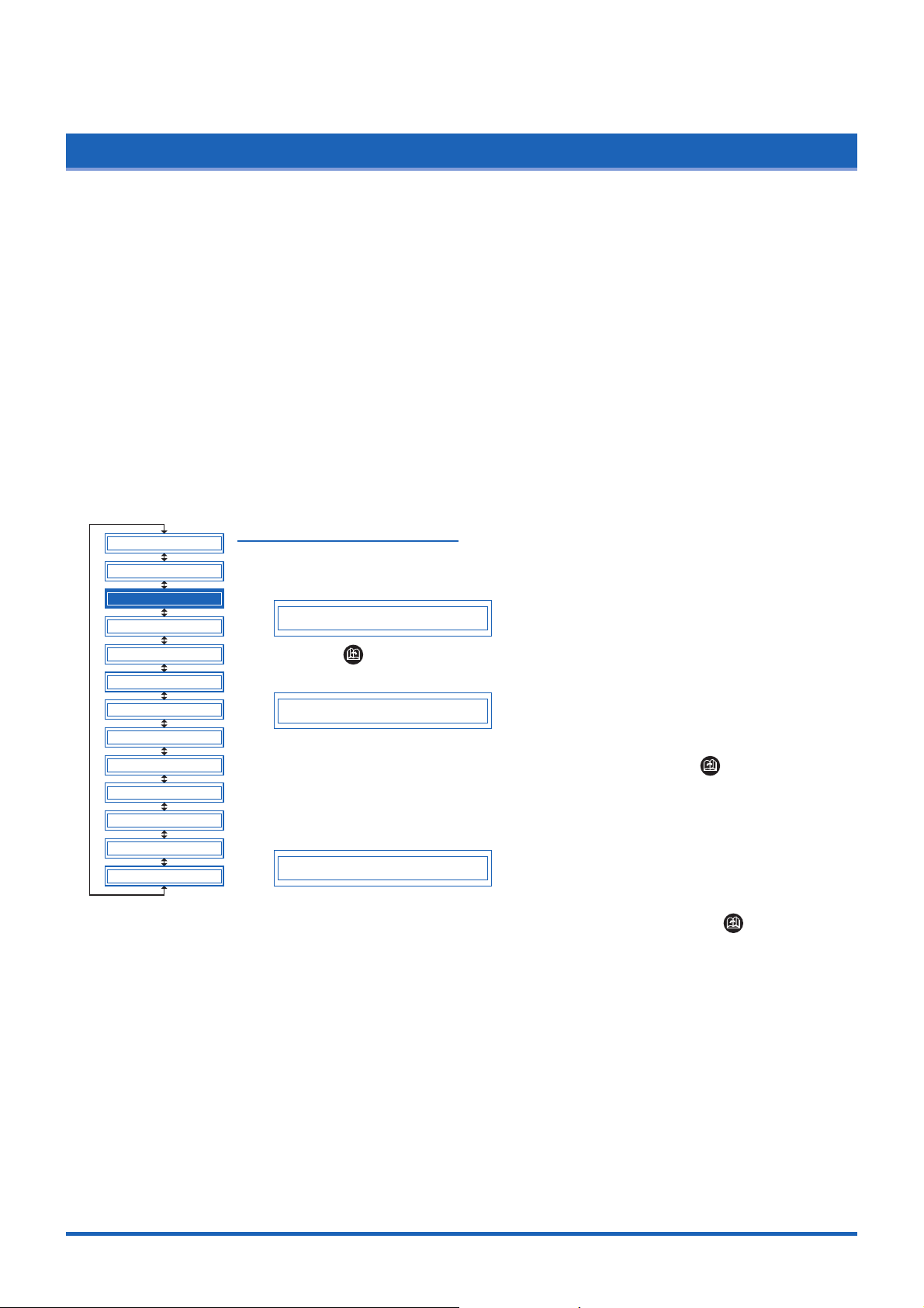
4.1 PAUSE Menu List
Pressing the (PAUSE) key in READY mode displays the PAUSE menu, enabling the various settings to
be made. Select the required menu by scrolling through the list using the (NEXT) or (PREV.) key.
(ENTER) key
CLEAR BUFFER
FEED&CUT
BLADE WARE SETUP
PEN UP/DOWN
CUT LINE PAT.
TANGENTIAL
INIT. B
PEN UP SPEED
INITIAL FEED
AUTO PRE FEED
ADVANCED FUNC.
SETUP MENU
TEST
4.2 Clearing the Buffer Memory
4.3 Setting the FEED & CUT function
4.4 Blade Wear Detection (When Blade Wear Setup is On)
4.5 Raising and Lowering the Pen
4.6 Selecting the Type of Perforated Line.
4.7 Setting TANGENTIAL Mode
4.8 Selecting the Blade Tip's Initial Position
4.9 Setting the PEN UP SPEED
4.10 Specifying the INITIAL FEED Length
4.11 Setting AUTO PRE-FEED
(ENTER) key
4.35 TEST Mode
DISTANCE ADJUST
4.12 Distance Adjustment
SELECT USER
COMMAND
RS-232C
PAGE LENGTH
SEPARATOR
TIMEOUT
PAPER READY TIME
PAPER LOAD
4.27 User-specified Settings
4.28 Setting the Format of Data to be Received
4.29 Interface Settings
4.30 Setting the PAGE LENGTH
4.31 Setting the SEPARATOR Function
4.32 Setting the TIMEOUT Function
4.33 Setting the PAPER READY TIME
4.34 Setting the PAPER LOAD Function
AXIS ALIGNMENT
PLOT AREA
EXPAND
ROTATE
SORT
SPACE REAR
OFFSET FORCE
INIT. DOWN FORCE
STEP PASS
OFFSET ANGLE
F_CUT
LENGTH UNIT
PEN 1/2 ADJ
COPY
4.13 Aligning the Coordinate Axes
4.14 Setting the Cutting/Plotting Area
4.15 Expanding the Cutting/Plotting Area
4.16 Rotating the Coordinate Axes
4.17 Sorting Settings
4.18 Specifying the SPACE REAR Distance
4.19 Setting the OFFSET FORCE (Initial Cutting Force)
4.20 Setting the Initial Down Force
4.21 Setting the STEP PASS
4.22 Setting the OFFSET ANGLE
4.23 Setting the F_CUT Function
4.24 Setting the LENGTH UNIT
4.25 Adjusting the Distance Between the Pens
4.26 Cutting/Plotting Using the Buffer Memory (COPY Function)
4-2
Page 50

Function Settings and Operations
4.2 Clearing the Buffer Memory
This function deletes the data sent to the cutting plotter. It is used to abort cutting while it is in progress.
CLEAR BUFFER
FEED&CUT
BLADE WARE SETUP
PEN UP/DOWN
CUT LINE PAT.
TANGENTIAL
INIT. B
PEN UP SPEED
INITIAL FEED
AUTO PRE FEED
ADVANCED FUNC.
SETUP MENU
TEST
(1) Press the (PAUSE) key to switch to PAUSE mode.
(2) Stop the transmission of data from the computer if this is in progress.
(3) Press the (NEXT) or (PREV.) key until the following menu is displayed.
CLEAR BUFFER
(4) Press the (ENTER) key to display the clear-buffer-memory menu.
CLEAR <YES>
(5) Press the or key to select "YES" or "NO," and then press the
(ENTER) key. To cancel the selection, select "NO" and press the (ENTER)
key, or press the (NEXT) or (PREV.) key .
4-3
Page 51

Function Settings and Operations
4.3 Setting the FEED & CUT function
TThis function enables cross-cutting of the medium. Cutting is performed after one page has been fed. The
page length is the length specified in Section 4.30 "Setting the Page Length.
CLEAR BUFFER
FEED&CUT
BLADE WARE SETUP
PEN UP/DOWN
CUT LINE PAT.
TANGENTIAL
INIT. B
PEN UP SPEED
INITIAL FEED
AUTO PRE FEED
ADVANCED FUNC.
SETUP MENU
TEST
(1) Press the (PAUSE) key to switch to PAUSE mode.
(2) Press the (NEXT) or (PREV.) key until the following menu is displayed.
FEED&CUT
(3) Press the (ENTER) key to display the FEED & CUT menu.
FEED&CUT CUT
(4) Press the or key to select "FEED&CUT" or "CUT", and then press the
(ENTER) key. To cancel the selection, press the (NEXT) or (PREV.)
key.
If "CUT" is selected, cross-cutting is performed at the current pen position.
If "FEED&CUT" is selected, cross-cutting is performed after one page has been
fed.
4-4
Page 52
Function Settings and Operations
4.4
Blade Wear Detection (When Blade Wear Setup is On)
This function calculates the total cutting distance of the cutter blade to indicate when it requires replacement.
This should be used purely as a guide, as the actual cutter-blade wear will vary depending on the material
cut and the cutting conditions (e.g., force) used.
The pen setting areas are grouped together, and the total distances are calculated for each group. Eight
groups can be managed, and they initially correspond to the pen setting areas, so that group 1 corresponds
to setting area 1, group 2 corresponds to setting area 2, and so on. If two or more setting areas are
combined in a single group, the total calculated distance for that group will be the sum of the individual area
values.
It is also possible to include weighting factors for each setting area to correspond to the different wear rates
for different materials and cutting conditions. For example, if setting areas 1, 2, and 3 are combined into one
group with respective total distances of A, B, and C, and the respective factors are 0.7, 1.2, and 1.0, the total
distance for this group will be A x 0.7 + B x 1.2 + C x 1.0.
Wear detection can be switched on or off using the special function settings (see "Enabling/Disabling Blade
Wear Detection" on page 5-3). When disabled, it is not displayed on the PAUSE menu.
If the power is turned off while cutting is in progress, the cutting distance for that operation is not included in
wear-detection calculations.
CLEAR BUFFER
FEED&CUT
BLADE WARE SETUP
PEN UP/DOWN
Checking the Wear Rate
(1) Check to confirm that the cutting plotter is in READY mode (displaying the current
pen settings).
1 PEN 23 30 2
CUT LINE PAT.
TANGENTIAL
INIT. B
PEN UP SPEED
INITIAL FEED
AUTO PRE FEED
ADVANCED FUNC.
SETUP MENU
TEST
(2) Press the (NEXT) key to display the wear-rate menu for the group to which
the above setting area belongs.
BLADE WEAR 60%
The wear rate is shown as 0% for a new pen, and 100% when the total distance
exceeds the maximum distance for the cutter blade. Press the (PREV.) key to
return to READY mode.
(3) The following message is displayed in READY mode if the wear rate exceeds
100% for the group to which the current setting area belongs.
EXCEEDS 100%
This indication should be used as a guide for cutter-blade replacement.
This display reverts to the normal READY-mode display when the (PREV.) key
is pressed, but it will reappear when the power is turned on again or if a setting
area is selected again for a group with a wear rate exceeding 100%.
Always zero the total distance display after replacing a cutter blade (see "Clearing
the Total Distance (Wear Rate)"). The display above will disappear, and the
distance calculation will restart from zero.
4-5
Page 53

Function Settings and Operations
Setting Wear -Rate Groups
This registers setting areas in groups.
(1) Press the (PAUSE) key to switch to PAUSE mode.
(2) Press the (NEXT) or (PREV.) key until the following menu is displayed.
(3) Press the (ENTER) key to display the wear-rate setting submenu.
(4) Press the (ENTER) key to display the wear-rate group setting.
(5) The number on the left is the group number, and the numbers to the right of this
BLADE WEAR SETUP
SET BLADE GROUP
GROUP 1 12 45
indicate the setting areas belonging to it, separated by spaces. The display above
indicates setting areas 1, 2, 4, and 5, belonging to group 1.
Use the or key to move the cursor to the group number or setting-area
number to be set. Pressing the or key at the group-number position
increases or decreases the number, and pressing the or key at the
setting-area number position displays or doesn't display the number. Select the
required group number, display the setting-area numbers to be registered, and
then press the (ENTER) key to confirm.
Each setting area can only be registered in one group. To register a setting area in
another group, it must first be removed from the group in which it is registered.
Initially, setting area 1 is set to group 1, setting area 2 to group 2, and so on, so
setting areas must be removed from one group before being registered in another.
To cancel the selection(s), press the (NEXT) or (PREV.) key.
Setting Wear -Rate Factors
This sets factors corresponding to the differences in wear rates due to different
materials and cutting conditions.
(1) Press the (PAUSE) key to switch to PAUSE mode.
(2) Press the (NEXT) or (PREV.) key until the following menu is displayed.
BLADE WEAR SETUP
(3) Press the (ENTER) key to display the wear-rate setting submenu, and
then press the (NEXT) or (PREV.) key until the following menu is
displayed.
FACTOR
(4) Press the (ENTER) key to display the wear-rate factor setting.
COND 1 1.00
(5) Use the or key to increase or decrease the setting-area number, and use the
or key to increase or decrease the factor value . The factor can be set to
between 0.10 and 1.00 in 0.10 intervals, and between 1.00 and 2.50 in 0.25
intervals. Once the w ear-rate factor is set, press the (ENTER) key to confirm. To
cancel the selection(s), press the (NEXT) or (PREV.) key.
4-6
(6) Press the (PAUSE) key to cancel PAUSE mode.
Page 54

Function Settings and Operations
Clearing the Total Distance (Wear Rate)
Always zero the total-distance display when a cutter blade has been replaced. This
starts the total-distance calculation from zero.
(1) Press the (PAUSE) key to switch to PAUSE mode.
(2) Press the (NEXT) or (PREV.) key until the following menu is displayed.
BLADE WEAR SETUP
(3) Press the (ENTER) key to display the wear-rate setting submenu, and
then press the (NEXT) or (PREV.) key until the following menu is
displayed.
CLEAR GROUP
(4) Press the (ENTER) key to display the wear-rate clear menu.
CLR GROUP1 <YES>
(5) The number to the right of "CLEAR GROUP" is the group number. Use the or
key to increase or decrease the group number, and press the or key to
select "YES" or "NO." Select "YES" f or the g roup number to be cleared, and press
the (ENTER) key to clear the total distance. To cancel the selection(s), press the
(NEXT) or (PREV.) key.
(6) Press the (PAUSE) key to cancel PAUSE mode.
4-7
Page 55

Function Settings and Operations
4.5 Raising and Lowering the Pen
This function raises and lowers the pen.
CLEAR BUFFER
FEED&CUT
BLADE WARE SETUP
PEN UP/DOWN
CUT LINE PAT.
TANGENTIAL
INIT. B
PEN UP SPEED
INITIAL FEED
AUTO PRE FEED
ADVANCED FUNC.
SETUP MENU
TEST
(1) Press the (PAUSE) key to switch to PAUSE mode.
(2) Press the (NEXT) or (PREV.) key until the following menu is displayed.
PEN UP/DOWN
(3) Press the (ENTER) key to lower the pen, and press the (ENTER) key
again to raise it.
4-8
Page 56
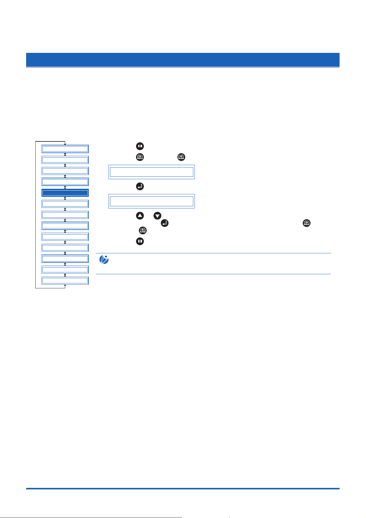
Function Settings and Operations
4.6 Selecting the Type of Perforated Line
The CUT LINE PAT. function lets you specify one of seven types of cut lines from 0 to 6. If you select OFF, a
solid line is cut. The default setting is 6. Change this setting if the shapes being cut either separate too easily
or are hard to separate.
Using this function, you can select the cut line pattern ratio (the ratio of cut segments to uncut segments in
each line) by specifying the LINE TYPE NO. The smaller the value, the shorter the uncut segments and the
easier it is for cut shapes to be separated. When the specified LINE TYPE NO. properly suits the medium you
are using, cut shapes can be easily separated after cutting but will not come loose during cutting.
CLEAR BUFFER
FEED&CUT
BLADE WARE SETUP
PEN UP/DOWN
CUT LINE PAT.
TANGENTIAL
INIT. B
PEN UP SPEED
INITIAL FEED
AUTO PRE FEED
ADVANCED FUNC.
SETUP MENU
TEST
(1) Press the (PAUSE) key to switch to PAUSE mode.
(2) Press the (NEXT) or (PREV.) key until the following menu is displayed.
CUT LINE PAT.
(3) Press the (ENTER) key to display the PERF. LINE TYPE setting.
LINE TYPE NO OFF
(4) Press the or key to select "OFF" or a value within the range "0" to" 6,"
and then press the (ENTER) key. To cancel the selection, press the
(NEXT) or (PREV.) key.
(5) Press the (PAUSE) key to cancel PAUSE mode.
CHECKPOINT
The setting is retained in the internal memory even when the power is turned off.
4-9
Page 57

Function Settings and Operations
4.7 Setting T ANGENTIAL Mode
This function should be used for the cutting of thick media (more than 0.3 mm in thickness) and when the
cutter blade is not able to turn properly due to the cutting depth, resulting in discrepancies between the start
and finish point and the inability to cut sharp corners. This function can be set on or off individually for each of
the eight cutter-pen setting areas, and it should be set to suit the media used. The overcut-amount setting
screen is displayed for cutter-pen setting areas for which the TANGENTIAL mode is "ON."
This setting has two modes: Mode 1 and Mode 2.
Mode 1: Overcuts the start and finish cutting positions and acute-angle corner sections to avoid leaving
uncut sections. In addition, the cutter blade is moved on the surface of the medium during cutting
when it is rotated significantly, ensuring sharp cutting unaffected by the medium toughness or
thickness.
Mode 2: Overcuts the start and finish cutting positions only. In addition, the cutter is rotated on the medium
surface for the start cutting position only. This uses simpler cutter control than Mode 1, and provides
a shorter cutting time.
CLEAR BUFFER
FEED&CUT
BLADE WARE SETUP
PEN UP/DOWN
CUT LINE PAT.
TANGENTIAL
INIT. B
PEN UP SPEED
INITIAL FEED
AUTO PRE FEED
ADVANCED FUNC.
SETUP MENU
TEST
(1) Press the (PAUSE) key to switch to PAUSE mode.
(2) Press the (NEXT) or (PREV.) key until the following menu is displayed.
TANGENTIAL
(3) Press the (ENTER) key to display the TANGENTIAL setting. The numbers "1"
to "8" indicate the cutter setting areas, and those marked with a s symbol have
the TANGENTIAL mode set to "ON."
1 2 3 4 5 6 7 8
Use the and key to move the cursor and select a setting area. Use the
and key to display/not display the s symbol, and then press the (ENTER)
key to confirm. To cancel the selection, press the (NEXT) or (PREV.) key.
(4) Press the (PAUSE) key to cancel PAUSE mode.
(5) Select the condition-setting area to be set to "ON" (refer to "Storing and Selecting
Cutter Pen Condition Setting Areas" on page 3-3).
5 15U 0 20 30 1
(6) Press the (ENTER) key or use the key to move the cursor to the right-
hand side, and then press the key again to display the menu shown below. If
the distance adjustment is set for the setting area selected, the distance
adjustment will be displayed here. Either press the (ENTER) key or move the
cursor to the right-hand side and press the key.
4-10
TANGENTIAL MODE1
(7) Press the or key to select "Mode 1" or "Mode 2," and then press the
(ENTER) key. The overcut setting is displayed.
STR=0.2 END=0.2
(8) "STR" indicates the initial overcut amount, and "END" indicates the end
overcut amount for the line section. Press the or key to select "STR"
or "END", use the or key key to increase or decrease the values, and
then press the (ENTER) key to confirm. To cancel the selection(s), press
the (NEXT) or (PREV.) key.
Page 58

Function Settings and Operations
4.8 Selecting the Blade Tip's Initial Position
Whenever the cutting plotter is turned on or any of its cutting condition settings changed, initial blade control
is performed to position the cutter pen's blade on the medium so that the blade's tip is properly oriented. This
function is called the "Initial Blade Position".
When 2mm is selected, initial blade control is performed at a position 2 mm below the starting position for
cutting.
When OUTSIDE is selected, initial blade control is performed outside of the effective cutting area.
CLEAR BUFFER
FEED&CUT
BLADE WARE SETUP
PEN UP/DOWN
CUT LINE PAT.
TANGENTIAL
INIT. B
PEN UP SPEED
INITIAL FEED
AUTO PRE FEED
ADVANCED FUNC.
SETUP MENU
TEST
(1) Press the (PAUSE) key to switch to PAUSE mode.
(2) Press the (NEXT) or (PREV.) key until the following menu is displayed.
INIT. B
Press the (ENTER) key to display the INIT. BLADE POS. setting.
INIT. B 2mm
(3) Press the or key to select "2mm" or "OUTSIDE", and then press the
(ENTER) key. To cancel the selection, press the (NEXT) or (PREV.) key.
(4) Press the (PAUSE) key to cancel PAUSE mode.
CHECKPOINT
The setting is retained in the internal memory even when the power is turned off.
4-11
Page 59

Function Settings and Operations
4.9 Setting the PEN UP SPEED
This function sets the travel speed of the pen when it is raised. It can be specified independently of the
cutting SPEED function. When the PEN UP SPEED is high, the pen travels faster when it is raised, thereby
reducing the overall cutting time. Your cutting plotter comes with its PEN UP SPEED set to AUTO, which
selects the same speed as the cutting SPEED function (pen lowered). If long-axis cutting is performed with a
high PEN UP SPEED setting, the medium is susceptible to becoming caught up.
(1) Press the (PAUSE) key to switch to PAUSE mode.
CLEAR BUFFER
FEED&CUT
BLADE WARE SETUP
PEN UP/DOWN
(2) Press the (NEXT) or (PREV.) key until the following menu is displayed.
PEN UP SPEED
(3) Press the (ENTER) key to display the pen-up-speed menu.
CUT LINE PAT.
TANGENTIAL
INIT. B
PEN UP SPEED
INITIAL FEED
AUTO PRE FEED
ADVANCED FUNC.
SETUP MENU
TEST
UP SPEED = AUTO
Use the or key to select the value to be set, and then press the
(ENTER) key to confirm.
"AUTO" "30" "40" "50" "60" cm/s
To cancel the selection, press the (NEXT) or (PREV.) key.
(4) Press the (PAUSE) key to cancel PAUSE mode.
CHECKPOINT
This setting is retained in the internal memory even when the power is turned off.
4-12
Page 60
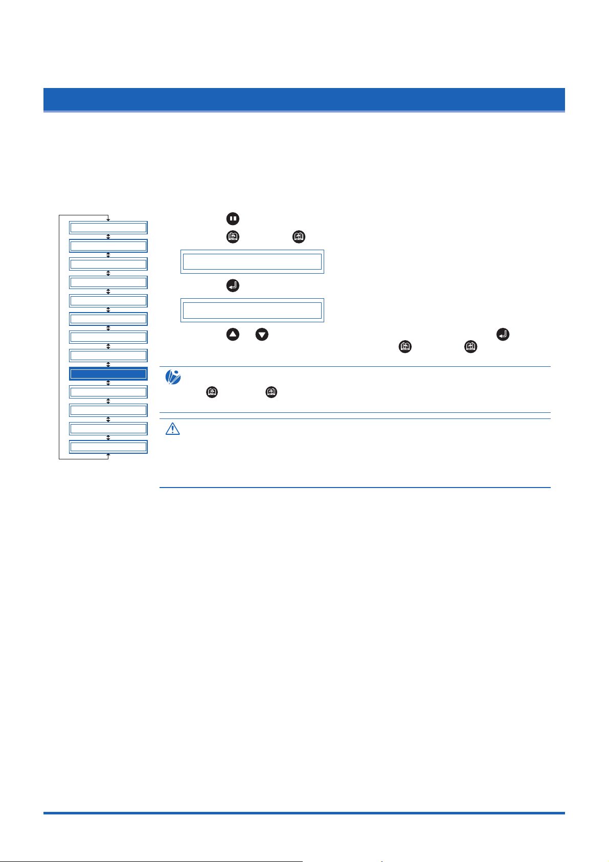
Function Settings and Operations
4.10 Specifying the INITIAL FEED Length
This function lets you select whether or not to perform an initial feed operation when the cutting plotter is
turned on, when the media set lever is raised and a medium reloaded, or when a new medium is loaded.
During an INITIAL FEED operation, the medium is automatically advanced while the grit rollers make marks
on the medium to prevent it from slipping. The distance the medium is fed is the distance specified in Section
4.30 "Setting the Page Length.
CLEAR BUFFER
FEED&CUT
BLADE WARE SETUP
PEN UP/DOWN
CUT LINE PAT.
TANGENTIAL
INIT. B
PEN UP SPEED
INITIAL FEED
AUTO PRE FEED
ADVANCED FUNC.
SETUP MENU
TEST
(1) Press the (PAUSE) key to switch to PAUSE mode.
(2) Press the (NEXT) or (PREV.) key until the following menu is displayed.
INITIAL FEED
(3) Press the (ENTER) key to display the INITIAL FEED setting.
INITIAL FEED OFF
(4) Press the or key to select "OFF" or "ON", and then press the
(ENTER) key. To cancel the selection, press the (NEXT) or (PREV.) key.
CHECKPOINT
If the (NEXT) or (PREV.) key is pressed during a feed operation, the feed
operation will be terminated immediately and the medium returned to its original position.
CAUTION
When the initial feed operation has been specified and the power is turned on; the media
set lever raised and a medium loaded; or a new medium loaded; the feed operation will
start immediately. Make sure that there are no obstacles in front of or behind the cutting
plotter.
4-13
Page 61
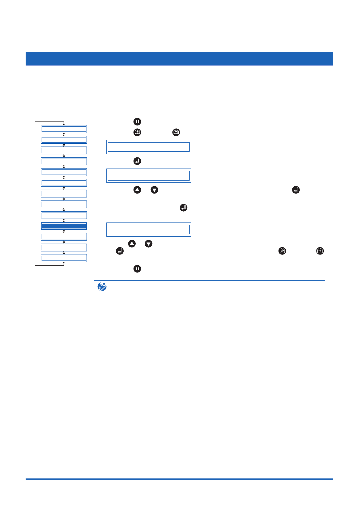
Function Settings and Operations
4.11 Setting AUTO PRE-FEED
When the AUTO PRE-FEED function is set to "ON," the medium is automatically fed forward and backward
by the preset length when data is received. This operation leaves traces of the grit rollers on the media and
prevents it from slipping during a cutting or plotting operation. Similarly, if roll media is used, the medium is
automatically pulled out by the cutting plotter.
(1) Press the (PAUSE) key to switch to PAUSE mode.
CLEAR BUFFER
FEED&CUT
BLADE WARE SETUP
(2) Press the (NEXT) or (PREV.) key until the following menu is displayed.
AUTO PRE FEED
PEN UP/DOWN
CUT LINE PAT.
TANGENTIAL
INIT. B
PEN UP SPEED
INITIAL FEED
AUTO PRE FEED
ADVANCED FUNC.
SETUP MENU
TEST
(3) Press the (ENTER) key to display the AUTO PRE-FEED setting.
AUTO PRE FEED ON
Press the or key to select "ON" or "OFF," and then press the
(ENTER) key to confirm.
(4) If "ON" is selected and the (ENTER) key pressed, the feed-length setting is
displayed.
AUTO PRE FEED 1m
Use the or key to set a value within the range of 1 m to 50 m, and then press
the (ENTER) key to confirm. To cancel the selection, press the (NEXT) or
(PREV.) key.
(5) Press the (PAUSE) key to cancel PAUSE mode.
CHECKPOINT
This setting is retained in the memory even when the power is turned off.
4-14
Page 62

Function Settings and Operations
4.12 Distance Adjustment
This function corrects any deviation in the length of cut or the plotted line segments, which occurs depending
on the medium being used. The adjustment value for the deviation is specified as a percentage of the total
distance. For example, a setting of 0.05% adjusts a distance of 2 m (2,000 mm) by +1 mm (2000 x 0.05% = 1
mm), to become 2,001 mm. Eight different cutter-pen condition-setting areas can be set on or off separately,
allowing different settings to be made in order to suit the medium used.
CLEAR BUFFER
FEED&CUT
BLADE WARE SETUP
PEN UP/DOWN
CUT LINE PAT.
TANGENTIAL
INIT. B
PEN UP SPEED
INITIAL FEED
AUTO PRE FEED
ADVANCED FUNC.
SETUP MENU
TEST
(1) Press the (PAUSE) key to switch to PAUSE mode.
(2) Press the (NEXT) or (PREV.) key until the following menu is displayed.
ADVANCED FUNC.
(3) Press the (ENTER) key, and then press the (NEXT) or (PREV.) key
until the following menu is displayed.
DISTANCE ADJUST
(4) Press the (ENTER) key to display the distance adjustment menu. The
numbers "1" to "8" indicate the cutter-pen condition-setting areas, and those that
are set on are indicated with the ssymbol to the left.
1 2 3 4 5 6 7 8
Use the or key to move the cursor to select the required condition-
setting area. Press the or key to display or not display thes symbol,
and then press the (ENTER) key to confirm. To cancel, press the
(NEXT) or (PREV.) key.
(5) Press the (PAUSE) key to cancel PAUSE mode.
(6) Select the condition-setting area to be set to "ON" (refer to "Selecting Cutter-Pen-
Condition Setting Areas" on page 3-6).
5 15U 0 20 30 1
(7) Either press the (ENTER) key or use the key to move the cursor to the far
right, and then press the key to display the following menu.
X= 0.00%Y= 0.00%
(8) Select "X" or "Y" using the or key. Use the or key to increase or
decrease the setting within the range of "-2.00%" to "+2.00%," and then press
the (ENTER) key to confirm. If the condition-setting area is set for
TANGENTIAL mode, the TANGENTIAL-mode setting will be displayed. Press
(ENTER) again. To cancel the selection(s), press the (NEXT) or (PREV.)
key.
CHECKPOINT
This setting is retained in the memory even when the power is turned off.
4-15
Page 63

Function Settings and Operations
4.13 Aligning the Coordinate Axes
This function is used to compensate for any offset in the origin or angular deviation in the coordinate axes
that occurs when a medium plotted in another plotter is loaded or when a previously plotted medium is
reloaded. This function enables the cutting of outlines plotted using a different plotter, or drawings previously
plotted to be recut. Plotting the origin and X-axis line before the coordinate axes are aligned makes it easier
to adjust the axes. Plot the origin and X-axis line within the plotting area to enable settings to be specified
even if the X-axis and origin are positioned at an angle. If the origin and X-axis line are plotted near the
boundaries of the plotting area, the settings may lie outside the plotting area, making it impossible to align
the axes.
Reloaded medium already plotted
Alignment
point 2
Drawing
reference points
Y
Offset between plotted medium and
cutting-plotter X/Y-axis and origin
CLEAR BUFFER
FEED&CUT
BLADE WARE SETUP
PEN UP/DOWN
CUT LINE PAT.
TANGENTIAL
INIT. B
PEN UP SPEED
INITIAL FEED
(1) Press the (PAUSE) key to switch to PAUSE mode.
(2) Press the (NEXT) or (PREV.) key until the following menu is displayed.
(3) Press the (ENTER) key, and then press the (NEXT) or (PREV .) key
(4) Press the (ENTER) key to display the axis-alignment menu.
Axis alignment
X
Alignment point 1
Origin
Cutting-plotter reference point
(Origin on previously plotted medium)
ADVANCED FUNC.
until the following menu is displayed.
AXIS ALIGNMENT
PT1 0, 0
X
Y
New origin
X/Y-axis and origin offset corrected
AUTO PRE FEED
ADVANCED FUNC.
SETUP MENU
TEST
4-16
Use the , , , and (POSITION) keys to move the cutter pen to
alignment point 1 (the origin on the previously plotted medium). The coordinates
displayed here indicate the distance from the current origin point.
(5) Press the (ENTER) key to set the new origin, and use this as the center of
rotation for the X-axis.
(6) Use the , , , and (POSITION) keys to move the cutter pen to
alignment point 2 (any point on the X-axis for the previously plotted medium). The
coordinates displayed here indicate the distance from alignment point 1.
PT2 0, 0
(7) Press the (ENTER) key to calculate the X-axis angle of inclination and align
the axes.
Page 64

Function Settings and Operations
(8) Press the (PAUSE) key to cancel PAUSE mode.
CHECKPOINT
After the axes are aligned, the settings will be reset if any of the following are performed.
• Specification of a new origin
• Loading of a new medium
• Setting of the axis rotation
4-17
Page 65

Function Settings and Operations
4.14 Setting the Cutting/Plotting Area
This function allows the area in which cutting/plotting will be performed to be specified, thereby preventing
cutting/plotting outside the specified area. This function enables more efficient use of the medium through the
specification of uncut portions of a medium that have already been cut, to avoid the previously cut areas.
Note that setting of the cutting/plotting area also repositions the origin point in accordance with the
movement of the cutting area.
Cutting/plotting in this area only
Upper-right
setting
position
Lower-left setting position
Y
X
CLEAR BUFFER
FEED&CUT
BLADE WARE SETUP
PEN UP/DOWN
CUT LINE PAT.
TANGENTIAL
INIT. B
PEN UP SPEED
INITIAL FEED
AUTO PRE FEED
ADVANCED FUNC.
SETUP MENU
TEST
(1) Press the (PAUSE) key to switch to PAUSE mode.
(2) Press the (NEXT) or (PREV.) key until the following menu is displayed.
ADVANCED FUNC.
(3) Press the (ENTER) key, and then press the (NEXT) or (PREV .) key
until the following menu is displayed.
PLOT AREA
(4) Press the (ENTER) key to display the plotting-area menu.
LL 0, 0
(5) Use the , , , and (POSITION) keys to move the pen to the lower-left
setting position, and then press the (ENTER) key. The coordinates of the
lower-left position set are displayed. To make the default setting, press the
(ORIGIN) key.
(6) Once the lower-left position has been set, the coordinates for the upper-right
position are displayed. Set these coordinates in the same way as for the lower-left
position.
(7) Press the (PAUSE) key to cancel PAUSE mode.
4-18
CHECKPOINT
The following message is displayed if the lower-left and upper-right settings are not
separated by a distance of at least 5 mm. If this message appears, reset the lower-left
and upper-right positions.
WRONG PLOT AREA
Page 66

Function Settings and Operations
4.15 Expanding the Cutting/Plotting Area
This function allows the width of the cutting/plotting area to be extended by 9.5 mm on both sides, for a total
increase of 19 mm, enabling cutting to be performed up to the area in which the pinch rollers are positioned.
CLEAR BUFFER
FEED&CUT
BLADE WARE SETUP
PEN UP/DOWN
CUT LINE PAT.
TANGENTIAL
INIT. B
PEN UP SPEED
INITIAL FEED
AUTO PRE FEED
ADVANCED FUNC.
SETUP MENU
TEST
(1) Press the (PAUSE) key to switch to PAUSE mode.
(2) Press the (NEXT) or (PREV.) key until the following menu is displayed.
ADVANCED FUNC.
(3) Press the (ENTER) key, and then press the (NEXT) or (PREV .) key
until the following menu is displayed.
EXPAND
(4) Press the (ENTER) key to display the plotting-area width-setting menu.
EXPAND OFF
Press the or key to select "ON" or "OFF," and then press the
(ENTER) key to confirm. To cancel the selection, press the (NEXT) or
(PREV.) key.
(5) If the settings are not changed, press the (PAUSE) key to cancel PAUSE
mode. If the settings are changed, the media-type selection menu is displayed.
ROLL2 PRESS ENTR
(6) For details on the media loading and selection procedures, refer to "2.3 Loading
the Medium."
CHECKPOINT
This setting is retained in the memory even when the power is turned off.
4-19
Page 67

Function Settings and Operations
4.16 Rotating the Coordinate Axes
This function allows the cutting/plotting origin and coordinate axes to be rotated as shown below.
New origin
Y
When axis-coordinate
X
rotation is "on"
Y
Origin
When axiscoordinate
rotation is "off"
X
CLEAR BUFFER
FEED&CUT
BLADE WARE SETUP
PEN UP/DOWN
CUT LINE PAT.
TANGENTIAL
INIT. B
PEN UP SPEED
INITIAL FEED
AUTO PRE FEED
ADVANCED FUNC.
SETUP MENU
TEST
(1) Press the (PAUSE) key to switch to PAUSE mode.
(2) Press the (NEXT) or (PREV.) key until the following menu is displayed.
ADVANCED FUNC.
(3) Press the (ENTER) key, and then press the (NEXT) or (PREV .) key
until the following menu is displayed.
ROTATE
(4) Press the (ENTER) key to display the coordinate-axis rotation-setting menu.
ROTATE OFF
Press the or key to select "ON" or "OFF," and then press the
(ENTER) key to confirm. To cancel the selection, press the (NEXT) or
(PREV.) key.
(5) Press the (PAUSE) key to cancel PAUSE mode.
CHECKPOINT
This setting is retained in the memory even when the power is turned off.
4-20
Page 68
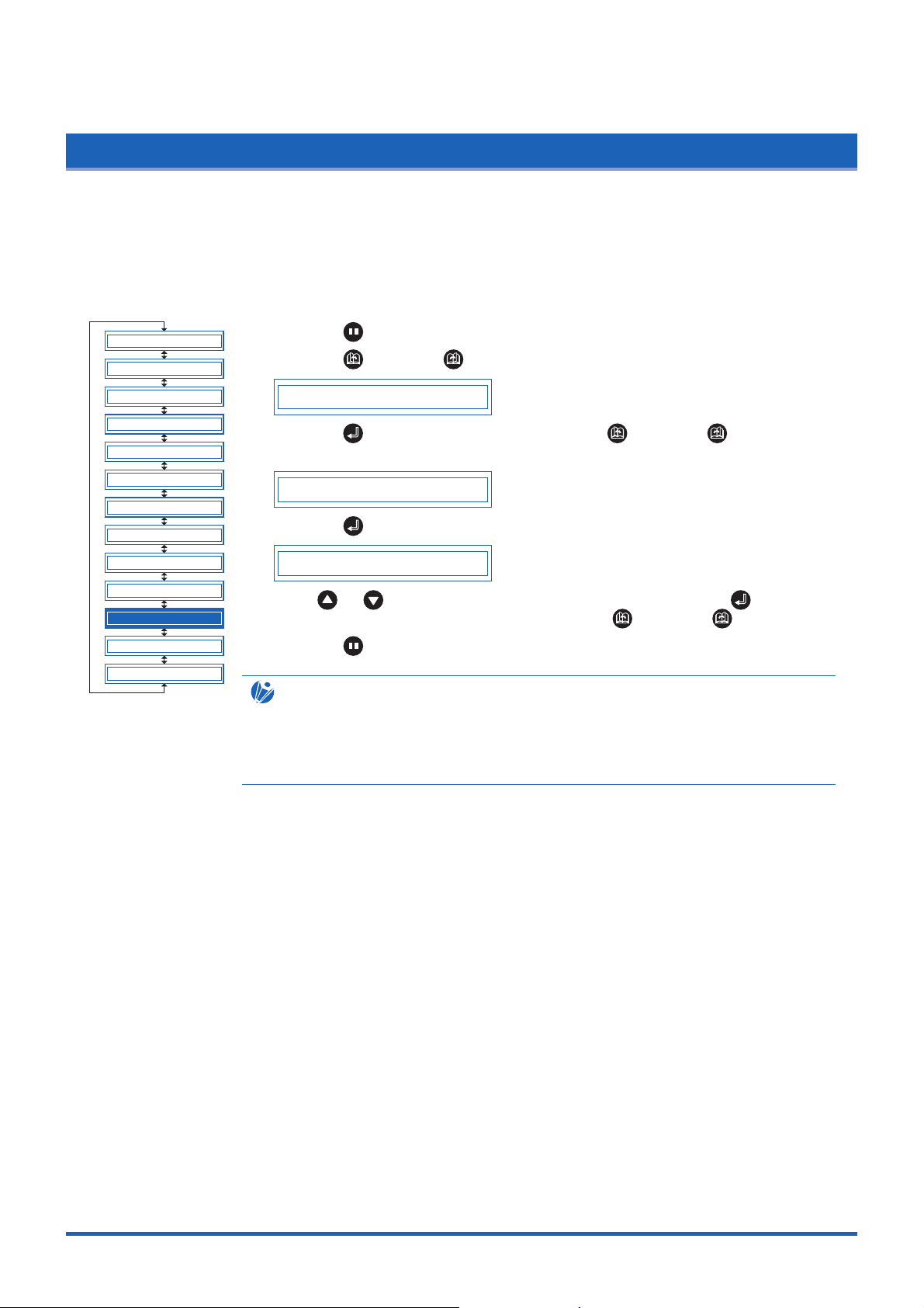
Function Settings and Operations
4.17 Sorting Settings
This function sorts the cutting/plotting data stored in the memory so that cutting is performed last when both
cutting and plotting operations are performed. This is useful for data requiring a large number of movements
on the drawing with the pen raised. If the data received has been sorted using the application software,
sorting the data using the cutting plotter may require additional time. Turning this function off may speed up
the process.
CLEAR BUFFER
FEED&CUT
BLADE WARE SETUP
PEN UP/DOWN
CUT LINE PAT.
TANGENTIAL
INIT. B
PEN UP SPEED
INITIAL FEED
AUTO PRE FEED
ADVANCED FUNC.
SETUP MENU
TEST
(1) Press the (PAUSE) key to switch to PAUSE mode.
(2) Press the (NEXT) or (PREV.) key until the following menu is displayed.
ADVANCED FUNC.
(3) Press the (ENTER) key, and then press the (NEXT) or (PREV .) key
until the following menu is displayed.
SORT
(4) Press the (ENTER) key to display the sorting setting menu.
SORT OFF
Press or key to select "ON" or "OFF", and then press the (ENTER)
key to confirm. To cancel the selection, press the (NEXT) or (PREV.) key.
(5) Press the (PAUSE) key to cancel PAUSE mode.
CHECKPOINT
• This setting is retained in the memory even when the power is turned off.
• If data for which the cutting/plotting sequence has been set using the application
software is received, the cutting/plotting sequence may be changed if this function is set
to "ON." The function should be set to "OFF" in this case.
4-21
Page 69

Function Settings and Operations
4.18 Specifying the SPACE REAR Distance
The SPACE REAR function specifies the trailing margin of the medium. When cross-cutting is performed on
the basis of the TIMEOUT or SEPARATOR setting, cross-cutting is initiated at a coordinate position which is
the maximum +X-axis position plotted plus the distance specified by the SPACE REAR setting.
CLEAR BUFFER
FEED&CUT
BLADE WARE SETUP
PEN UP/DOWN
CUT LINE PAT.
TANGENTIAL
INIT. B
PEN UP SPEED
INITIAL FEED
AUTO PRE FEED
ADVANCED FUNC.
SETUP MENU
TEST
(1) Press the (PAUSE) key to switch to PAUSE mode.
(2) Press the (NEXT) or (PREV.) key until the following menu is displayed.
ADVANCED FUNC.
(3) Press the (ENTER) key, and then press the (NEXT) or (PREV .) key
until the following menu is displayed.
SPACE REAR
(4) Press the (ENTER) key to display the SPACE REAR setting.
SPACE REAR= 12mm
Press the or key to specify the distance of the trailing margin within the
range of "7 mm" to "30 mm", and then press the (ENTER) key. To cancel
the selection, press the (NEXT) or (PREV.) key.
(5) Press the (PAUSE) key to cancel PAUSE mode.
CHECKPOINT
The setting is retained in the internal memory even when the power is turned off.
4-22
Page 70

Function Settings and Operations
4.19 Setting the OFFSET FORCE (Initial Cutting Force)
This function specifies the cutting force to be applied during initial blade control for checking the cutter-blade
direction at the start of operation. This is used to control the rotation of the cutter-blade tip during initial blade
control when thick media is cut, and is therefore not necessary to specify for media of regular thickness. The
initial setting is "4." Increasing this setting increases the cutting force.
(1) Press the (PAUSE) key to switch to PAUSE mode.
CLEAR BUFFER
FEED&CUT
BLADE WARE SETUP
(2) Press the (NEXT) or (PREV.) key until the following menu is displayed.
ADVANCED FUNC.
PEN UP/DOWN
CUT LINE PAT.
TANGENTIAL
INIT. B
PEN UP SPEED
INITIAL FEED
AUTO PRE FEED
ADVANCED FUNC.
SETUP MENU
TEST
(3) Press the (ENTER) key, and then press the (NEXT) or (PREV .) key
until the following menu is displayed.
OFFSET FORCE
(4) Press the (ENTER) key to display the offset-force setting menu.
OFFSET FORCE 4
Use the or key to select the required value within the range of "1" to
"31", and then press the (ENTER) key to confirm.
To cancel the selection, press the (NEXT) or (PREV.) key.
(5) Press the (PAUSE) key to cancel PAUSE mode.
CHECKPOINT
This setting is retained in the internal memory even when the power is turned off.
4-23
Page 71

Function Settings and Operations
4.20 Setting the Initial Down Force
The initial down-force setting is useful when TANGENTIAL mode is selected (for the cutting of thick media).
With a thick medium, additional time is required for the cutter blade to penetrate the medium fully, even when
the necessary cutting force is applied. The cutting operation starts before the cutter blade has fully
penetrated the medium, causing uncut sections to be left. When the initial down force is specified, this force
is used as the cutting force immediately after lowering of the pen when TANGENTIAL mode is selected,
enabling the cutter blade to penetrate the medium rapidly. (If the cutting force is 25 and the initial down force
is 4, for example, the cutting force applied immediately after lowering of the pen will be 29.) Set the initial
down force to suit the type of medium used by performing test cuts.
CLEAR BUFFER
FEED&CUT
BLADE WARE SETUP
PEN UP/DOWN
CUT LINE PAT.
TANGENTIAL
INIT. B
PEN UP SPEED
INITIAL FEED
AUTO PRE FEED
ADVANCED FUNC.
SETUP MENU
TEST
(1) Press the (PAUSE) key to switch to PAUSE mode.
(2) Press the (NEXT) or (PREV.) key until the following menu is displayed.
ADVANCED FUNC.
(3) Press the (ENTER) key, and then press the (NEXT) or (PREV .) key
until the following menu is displayed.
INIT.DOWN FORCE
(4) Press the (ENTER) key to display the initial-cutting-force setting menu.
INIT.DOWN F. 0
Use the or key to select the required value within the range of "0" to
"20," and then press the (ENTER) key to confirm. To cancel the selection,
press the (NEXT) or (PREV.) key.
(5) Press the (PAUSE) key to cancel PAUSE mode.
CHECKPOINT
The setting is retained in the internal memory even when the power is turned off.
4-24
Page 72
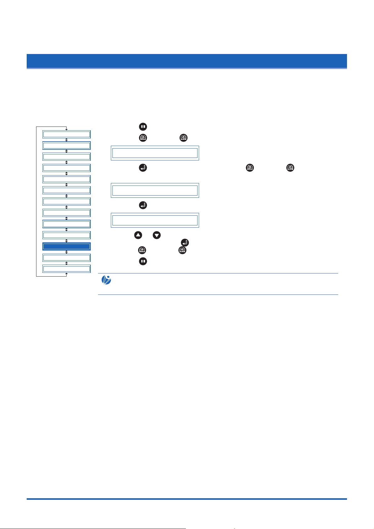
Function Settings and Operations
4.21 Setting the STEP PASS
Reducing this setting increases image quality by enabling smooth cutter-blade tip control when arcs are cut.
The STEP PASS setting specified is used as the unit for blade tip control, with blade tip control omitted for
any data below the STEP PASS setting. If the STEP PASS setting is too high, the image cut may not be
faithfully reproduced. Normally, the STEP PASS setting should be set to "1."
(1) Press the (PAUSE) key to switch to PAUSE mode.
CLEAR BUFFER
FEED&CUT
BLADE WARE SETUP
(2) Press the (NEXT) or (PREV.) key until the following menu is displayed.
ADVANCED FUNC.
PEN UP/DOWN
CUT LINE PAT.
TANGENTIAL
INIT. B
PEN UP SPEED
INITIAL FEED
AUTO PRE FEED
ADVANCED FUNC.
SETUP MENU
TEST
(3) Press the (ENTER) key, and then press the (NEXT) or (PREV .) key
until the following menu is displayed.
STEP PASS
(4) Press the (ENTER) key to display the step-pass setting menu.
STEP PASS 1
Use the or key to select the required value within the range of "0" to
"20," and then press the (ENTER) key to confirm. To cancel the selection,
press the (NEXT) or (PREV.) key.
(5) Press the (PAUSE) key to cancel PAUSE mode.
CHECKPOINT
This setting is retained in the internal memory even when the power is turned off.
4-25
Page 73

Function Settings and Operations
4.22 Setting the OFFSET ANGLE
This function sets the reference value used to adjust the cutter-blade offset angle to correspond to the
displacement of the traveling angle as defined by the coordinate movement data received. The cutter blade is
controlled above the angle specified. Setting a high value will reduce the total cutting time, but the corners of
drawings cut will become rounded and may not be cut precisely. The initial setting is "30."
(1) Press the (PAUSE) key to switch to PAUSE mode.
CLEAR BUFFER
FEED&CUT
BLADE WARE SETUP
(2) Press the (NEXT) or (PREV.) key until the following menu is displayed.
ADVANCED FUNC.
PEN UP/DOWN
CUT LINE PAT.
TANGENTIAL
INIT. B
PEN UP SPEED
INITIAL FEED
AUTO PRE FEED
ADVANCED FUNC.
SETUP MENU
TEST
(3) Press the (ENTER) key, and then press the (NEXT) or (PREV .) key
until the following menu is displayed.
OFFSET ANGLE
(4) Press the (ENTER) keyto display the offset-angle setting menu.
OFFSET ANGLE 30
Use the or key to select the required value within the range of "0" to
"60," and then press the (ENTER) key to confirm. To cancel the selection,
press the (NEXT) or (PREV.) key.
(5) Press the (PAUSE) key to cancel PAUSE mode.
CHECKPOINT
This setting is retained in the internal memory even when the power is turned off.
4-26
Page 74

Function Settings and Operations
4.23 Setting the F_CUT Function
When the COMMAND setting is GP-GL, the F_CUT function is used to enable or disable cross-cutting. When
the F_CUT function is enabled, cross-cutting of the medium will be performed even if the cutting plotter is
sent a feed command instructing it not to cut the medium.
CLEAR BUFFER
FEED&CUT
BLADE WARE SETUP
PEN UP/DOWN
CUT LINE PAT.
TANGENTIAL
INIT. B
PEN UP SPEED
INITIAL FEED
AUTO PRE FEED
ADVANCED FUNC.
SETUP MENU
TEST
(1) Press the (PAUSE) key to switch to PAUSE mode.
(2) Press the (NEXT) or (PREV.) key until the following menu is displayed.
ADVANCED FUNC.
(3) Press the (ENTER) key, and then press the (NEXT) or (PREV .) key
until the following menu is displayed.
F_CUT
(4) Press the (ENTER) key to display the F_CUT setting.
F_CUT ON
Press the or key to specify "ON" or "OFF", and then press the
(ENTER) key. To cancel the selection, press the (NEXT) or (PREV.) key.
(5) Press the (PAUSE) key to cancel PAUSE mode.
CHECKPOINT
The setting is retained in the internal memory even when the power is turned off.
4-27
Page 75

Function Settings and Operations
4.24 Setting the LENGTH UNIT
This function specifies the units for coordinates displayed in millimeters or inches.
CLEAR BUFFER
FEED&CUT
BLADE WARE SETUP
PEN UP/DOWN
CUT LINE PAT.
TANGENTIAL
INIT. B
PEN UP SPEED
INITIAL FEED
AUTO PRE FEED
ADVANCED FUNC.
SETUP MENU
TEST
(1) Press the (PAUSE) key to switch to PAUSE mode.
(2) Press the (NEXT) or (PREV.) key until the following menu is displayed.
ADVANCED FUNC.
(3) Press the (ENTER) key, and then press the (NEXT) or (PREV .) key
until the following menu is displayed.
LENGTH UNIT
(4) Press the (ENTER) key to display the length-unit menu.
LENGTH UNIT mm
Press the or key to select "mm" or "inch," and then press the
(ENTER) key to confirm. To cancel the selection, press the (NEXT) or
(PREV.) key.
(5) Press the (PAUSE) key to cancel PAUSE mode.
CHECKPOINT
The setting is retained in the internal memory even when the power is turned off.
4-28
Page 76
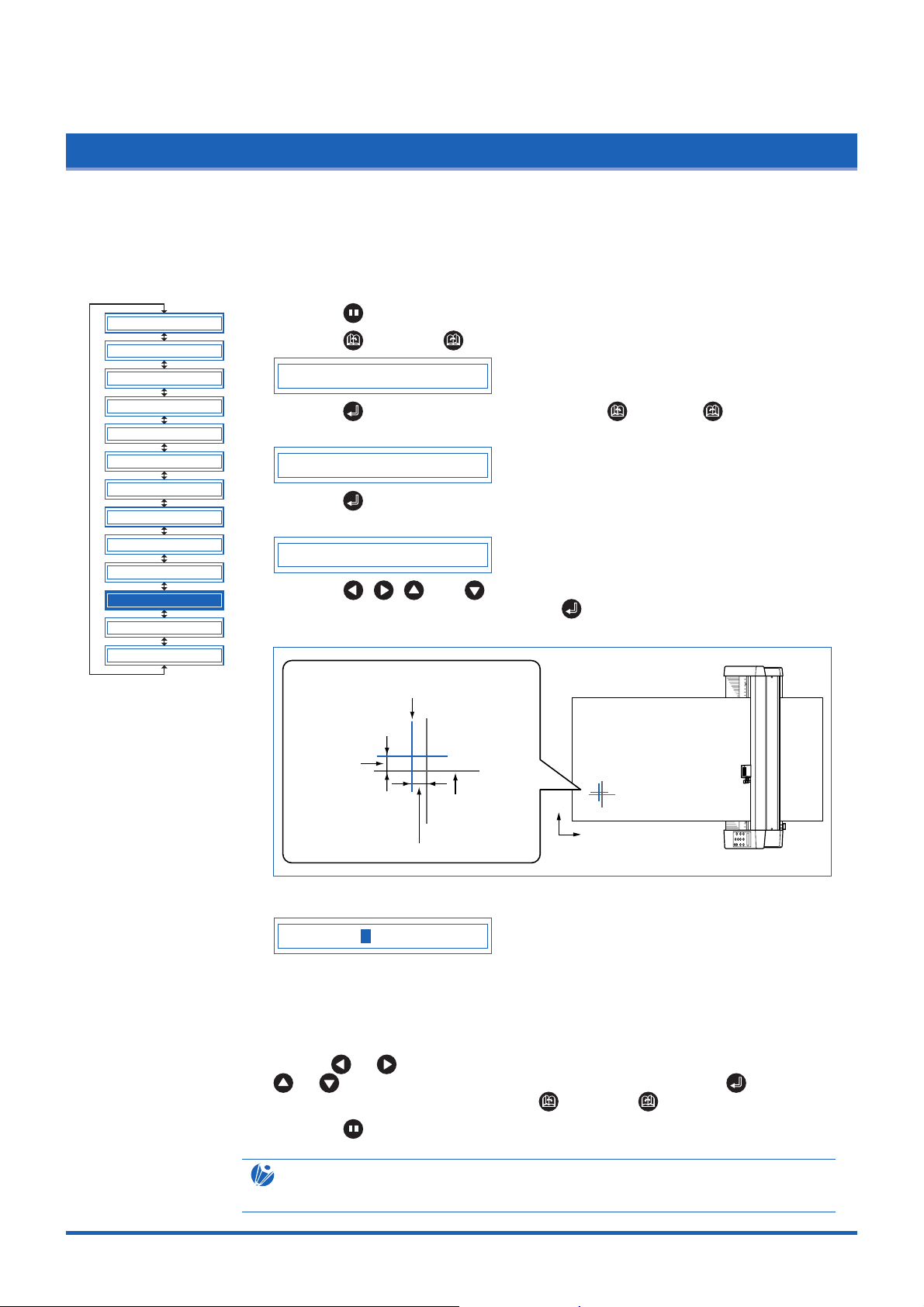
Function Settings and Operations
4.25 Adjusting the Distance Between the Pens
This function compensates for the difference in position between the cutter pen and the plotter pen. First of
all, mount a plotter pen in the pen station and draw a cross. Next, mount a cutter pen in the cutter pen holder
and cut a second cross (the reference cross). The difference between the two crosses can be adjusted by
inputting corrective values. The setting range is within -3.0 mm to +3.0 mm, in 0.1 mm intervals.
CLEAR BUFFER
FEED&CUT
BLADE WARE SETUP
PEN UP/DOWN
CUT LINE PAT.
TANGENTIAL
INIT. B
PEN UP SPEED
INITIAL FEED
AUTO PRE FEED
ADVANCED FUNC.
SETUP MENU
TEST
(1) Press the (PAUSE) key to switch to PAUSE mode.
(2) Press the (NEXT) or (PREV.) key until the following menu is displayed.
ADVANCED FUNC.
(3) Press the (ENTER) key, and then press the (NEXT)or (PREV.) key
until the following menu is displayed.
PEN 1/2 ADJ.
(4) Press the (ENTER) key, and then wait for the Pen Compensation Pattern
Prompt.
PLOT ADJ PAT.
(5) Press the , , , and (POSITION) keys to move the pen to the pattern
drawing start position, and then press the (ENTER) key to start drawing the
pattern.
The cross cut by the cutter pen
in the cutter pen holder. (the reference cross)
Compensation
value Y
The cross drawn
by the pen
in the pen holder.
Compensation value X
Y
X
(6) After the crosses have been drawn, the display changes to the following.
X= 0.0 Y= 0.0
Using the cross that was cut by the cutter pen mounted in the cutter pen holder as
the reference cross, input the values corresponding to the difference between the
reference cross and the first cross that was drawn. (In the drawing above, for
example, the difference is in the -X and +Y directions. In this case, input X = *mm, and Y = +*mm.)
Use the or keys to move the cursor to the items to be changed, and the
or keys to select the select the values and then press the (ENTER)
key. To cancel the selection, press the (NEXT) or (PREV.) key.
(7) Press the (PAUSE) key to cancel PAUSE mode.
CHECKPOINT
The setting is retained in the internal memory even when the power is turned off.
4-29
Page 77

Function Settings and Operations
4.26
Cutting/Plotting Using the Buffer Memory (COPY Function)
This function is used to make duplicate copies of cutting or plotting data that has been sent from the
computer and is retained in the cutting plotter's internal memory.
Origin
3rd copy
2nd copy
1st copy
Y
Copy origin(Initial
X
position for plotting copy)
6th copy
5th copy
4th copy
(1) Send the data to be copied to the cutting plotter, and cut or plot the data once.
CLEAR BUFFER
FEED&CUT
BLADE WARE SETUP
PEN UP/DOWN
CUT LINE PAT.
TANGENTIAL
INIT. B
(2) Use the , , , and (POSITION) keys to move the pen to the starting
position for cutting or plotting.
(3) Press the (PAUSE) key to switch to PAUSE mode.
(4) Press the (NEXT) or (PREV.) key until the following menu is displayed.
ADVANCED FUNC.
(5) Press the (ENTER) key, and then press the (NEXT)or (PREV.) key
until the following menu is displayed.
PEN UP SPEED
INITIAL FEED
AUTO PRE FEED
ADVANCED FUNC.
SETUP MENU
TEST
COPY
(6) Press the (ENTER) key to display the copy-setting menu.
COPY COUNT 1
(7) Use the or keys to select the desired number of copies, and then press
the (ENTER) key to confirm. To cancel the selection, press the (NEXT) or
(PREV.) key.
(8) The cutting/plotting operation starts for the number of copies selected.
(9) To make further copies, replace the medium and repeat steps 2 to 6.
If the data to be copied does not fit within the cutting/plotting area, the following message is displayed in step 5.
CANNOT COPY
Use the , , , and (POSITION) keys to change the initial copying
position or load a medium with an area of sufficient size to fit the copied data.
CHECKPOINT
• If the initial cutting/plotting position was moved from the original origin, the new origin
will also apply during the copying operation. To prevent wasteful use of the medium, the
initial cutting/plotting position for the data should be as close as possible to the origin.
• If the cutting plotter receives another set of data during the copying operation, the
operation will not be properly completed because the initial data is cleared during the
operation. Do not send new data to the cutting plotter while copying is in progress.
• If new data is sent to the cutting plotter more than 10 seconds after the initial cutting
data is sent, the original data will be cleared from the internal memory.
• Copying will not be possible if data exceeding 1.5 Mbytes is sent to the cutting plotter,
as the data will cause the buffer memory to overflow.
4-30
Page 78

Function Settings and Operations
4.27 User-specified Settings
This function loads the user-specified (CAD) settings. The COMMAND, ORIGIN POINT or STEP SIZE, RS232C TRANSMISSION CONDITIONS, SEPARATOR, TIMEOUT and PAGE LENGTH settings are set here.
CLEAR BUFFER
FEED&CUT
BLADE WARE SETUP
PEN UP/DOWN
CUT LINE PAT.
TANGENTIAL
INIT. B
PEN UP SPEED
INITIAL FEED
AUTO PRE FEED
ADVANCED FUNC.
SETUP MENU
TEST
(1) Press the (PAUSE) key to switch to PAUSE mode.
(2) Press the (NEXT) or (PREV.) key until the following menu is displayed.
SETUP MENU
(3) Press the (ENTER) key, and then press the (NEXT) or (PREV .) key
until the following menu is displayed.
SELECT USER
(4) Press the (ENTER) key to display the USER SETTINGS setting.
SELECT USER 1
Press the or key to specify a setting from "1" through "8", and then press
the (ENTER) key. To cancel the selection, press the (NEXT) or
(PREV.) key.
(5) Press the (PAUSE) key to cancel PAUSE mode.
Table of user-specified settings
USER No. 12345678
COMMAND HP-GL HP-GL GP-GL HP-GL HP-GL HP-GL HP-GL HP-GL
STEP SIZE 0.025 0.025 0.025 0.025 0.025 0.025 0.025 0.025
ORIGIN POINT
SEPARATOR PG NR JO SP PG SP None None
TIMEOUT 0 0 120 120 1 10 0 0
PAGE LENGTH (mm)
TRANSMISSION
CONDITIONS
STEP PASS –––––0––
PEN UP SPEED
F_CUTON –––––ON––
CUT LINE PAT. –––––OFF––
SPACE REAR –––––12 mm––
– : The currently selected value is used.
L.L. Center L.L. L.L. L.L. Center Center Center
1500 3000 1500 5000 3000 5000 5000 5000
9600, 9600, 9600, 9600, 9600, 19200, 9600, 9600,
N81X N81X N81X N81X N81X N81X N81X N81X
–––––
60 (cm/sec)
––
The cutter pen condition settings shown in the following table are the settings that
have been specified for USER 6.
Settings other than those shown in the table are the default settings.
Condition SPEED QUALITY FORCE Pen type OFFSET
No. (Acceleration) (Pen force) (Cutter blade) (Cutter offset)
160 1 17 Pen 0
230 1 14 09U 0
330 1 14 09U 0
430 1 14 09U 0
530 1 14 09U 0
630 1 14 09U 0
730 1 14 09U 0
860 1 14 09U 0
4-31
Page 79

Function Settings and Operations
4.28 Setting the Format of Data to be Received
Before data is sent from the computer, the format (command mode) of data sent by the application software
must be checked. The cutting plotter accepts two data formats (command modes): GP-GL (Graphtec) and
HP-GL commands. Set the command mode to suit the application used.
CLEAR BUFFER
FEED&CUT
BLADE WARE SETUP
PEN UP/DOWN
CUT LINE PAT.
TANGENTIAL
INIT. B
PEN UP SPEED
INITIAL FEED
AUTO PRE FEED
ADVANCED FUNC.
SETUP MENU
TEST
Setting the Command Mode
(1) Press the (PAUSE) key to switch to PAUSE mode.
(2) Press the (NEXT) or (PREV.) key until the following menu is displayed.
SETUP MENU
(3) Press the (ENTER) key, and then press the (NEXT) or (PREV .) key
until the following menu is displayed.
COMMAND
(4) Press the (ENTER) key to display the command-setting menu.
COMMAND GP-GL
(5) Press the or key to select "GP-GL" or "HP-GL," and then press the
(ENTER) key to confirm. To cancel the selection, press the (NEXT) or
(PREV.) key.
(6) If "GP-GL" is selected, set the STEP SIZE. If "HP-GL" is selected, set the
ORIGIN POINT. If a command different from that set previously is selected, the
PAUSE mode is automatically canceled after STEP SIZE (GP-GL) or ORIGIN
POINT (HP-GL) is set.
Setting the STEP SIZE
If the GP-GL command mode is set, the minimum unit of distance that the pen can
travel can be changed to one of four settings: 0.01 mm, 0.025 mm, 0.05 mm, or 0.1
mm. The default setting is 0.1 mm, so change this setting if your application specifies a
different step size.
(1) Set the command setting to "GP-GL."
COMMAND GP-GL
(2) Press the (ENTER) key to display the step-size setting menu.
STEP SIZE 0.100mm
(3) Press the or key to select "0.100 mm," "0.050 mm," "0.025 mm," or
"0.010 mm," and then press the (ENTER) key to confirm. To cancel the
selection, press the (NEXT) or (PREV.) key.
(4) Press the (PAUSE) key to cancel PAUSE mode.
4-32
Page 80

Function Settings and Operations
Setting the ORIGIN POINT
If the HP-GL command mode is set, the origin point can be set to the lower left or
center. The default setting is the lower left, so change this setting if your application
specifies a different origin position.
(1) Set the command setting to "HP-GL."
COMMAND HP-GL
(2) Press the (ENTER) key to display the origin-point setting.
ORIGIN PT L.L.
(3) Press the or key to select "L.L." (LOWER LEFT) or "CENTER," and
then press the (ENTER) key to confirm. To cancel the selection, press the
(NEXT) or (PREV.) key.
(4) Press the (PAUSE) key to cancel PAUSE mode.
4-33
Page 81

Function Settings and Operations
4.29 Interface Settings
The interface conditions must be set if the RS-232C serial interface is used, to ensure that the data-transfer
rate (baud rate), data length, and parity settings for the cutting plotter match those set in the application
software or computer operating system. This section describes the interface conditions for the cutting plotter.
For details on how to set the conditions for your application or computer operation system, refer to the
manual provided with the application or operating system.
CLEAR BUFFER
FEED&CUT
BLADE WARE SETUP
PEN UP/DOWN
CUT LINE PAT.
TANGENTIAL
INIT. B
PEN UP SPEED
INITIAL FEED
AUTO PRE FEED
ADVANCED FUNC.
SETUP MENU
TEST
(1) Press the (PAUSE) key to switch to PAUSE mode.
(2) Press the (NEXT) or (PREV.) key until the following menu is displayed.
SETUP MENU
(3) Press the (ENTER) key, and then press the (NEXT) or (PREV .) key
until the following menu is displayed.
RS-232C
(4) Press the (ENTER) key to display the interface-condition setting menu.
9600 N 8 H
The current settings are displayed (from left): transfer rate (baud rate), parity, data
length, and handshaking mode.
The baud rate can be set to "19200," "9600," "4800," "2400," "1200," "600," or
"300."
The parity can be set to "N" (None), "E" (Even parity), or "O" (Odd parity).
The data length can be set to "7" or "8" bits.
The handshaking mode can be set to "H" (hard-wired handshaking) or "X" (Xon/
Xoff handshaking). "E" (ENQ/ACK handshaking) can also be selected when the
command mode is set to HP-GL.
All of these interface conditions must be set to match the corresponding settings
in the application software and the computer operating system.
The parameter that can be changed is displayed immediately to the right of the s
mark. Use the or key to select the parameter to be changed, and use the
or key to select the setting details. Press the (ENTER) key to
confirm. To cancel the selection, press the (NEXT) or (PREV.) key.
4-34
(5) Press the (PAUSE) key to cancel PAUSE mode.
Page 82
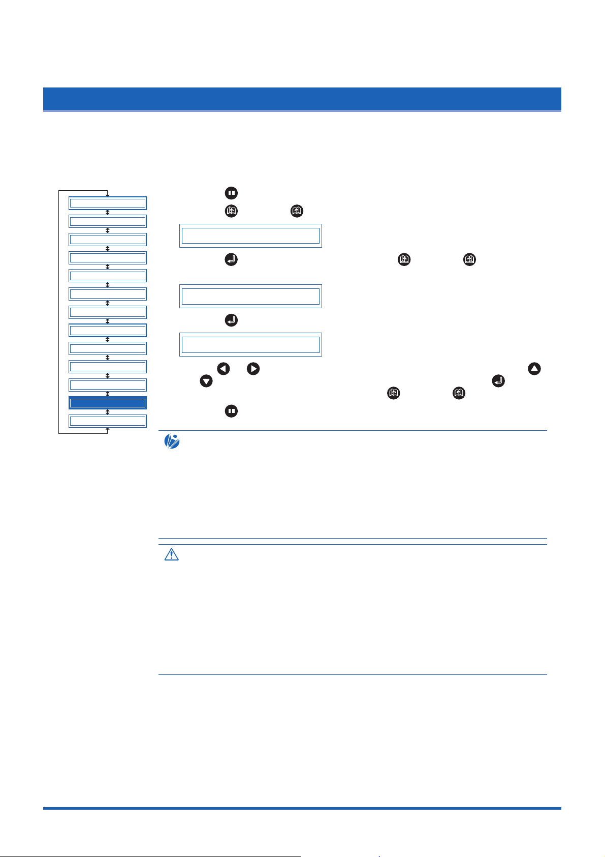
Function Settings and Operations
4.30 Setting the PAGE LENGTH
This function sets the length of each page when long-axis cutting or plotting is performed using a roll
medium. This should be set for long-axis cutting or plotting exceeding 5 m in length. The default setting is
"5000 mm."
CLEAR BUFFER
FEED&CUT
BLADE WARE SETUP
PEN UP/DOWN
CUT LINE PAT.
TANGENTIAL
INIT. B
PEN UP SPEED
INITIAL FEED
AUTO PRE FEED
ADVANCED FUNC.
SETUP MENU
TEST
(1) Press the (PAUSE) key to switch to PAUSE mode.
(2) Press the (NEXT) or (PREV.) key until the following menu is displayed.
SETUP MENU
(3) Press the (ENTER) key, and then press the (NEXT) or (PREV .) key
until the following menu is displayed.
PAGE LENGTH
(4) Press the (ENTER) key to display the page-length menu.
L=05000mm
Use the or key to move the cursor to the digit to be changed. Use the
and keys to increase or decrease the setting, and then press the
(ENTER) key to confirm. To cancel, press the (NEXT) or (PREV.) key.
(5) Press the (PAUSE) key to cancel PAUSE mode.
CHECKPOINT
• This setting is retained in the memory even when the power is turned off.
• The cutting plotter's distance precision is guaranteed for page-feed lengths of up to 3
meters. Long-axis cutting over 5 meters is possible for lengths of up to 50 meters in the
feeding direction.
• In the case of long-axis cutting, be particularly careful when loading the meduim. If the
meduim is loaded at even a slight angle, it may come loose from the rollers that hold it
in place.
CAUTION
• Before using roll paper, perform the pre-feed (see "4.10 Specifying the INITIAL FEED
LENGTH" and "4.11 Setting AUTO PRE-FEED") and paper acclimation (see "4.33
Setting the PAPER READY TIME" and "4.34 Setting the PAPER LOAD Function")
operations. (Precision is not guaranteed unless these operations are performed.)
• Make sure that the operating environment is within the range given for the guaranteed
precision operating environment and, in particular, that changes in temperature and
humidity are minimized insofar as possible.
• When cutting or plotting a long-axis design, use the paper receptacle (media basket)
with its opening widened.
4-35
Page 83
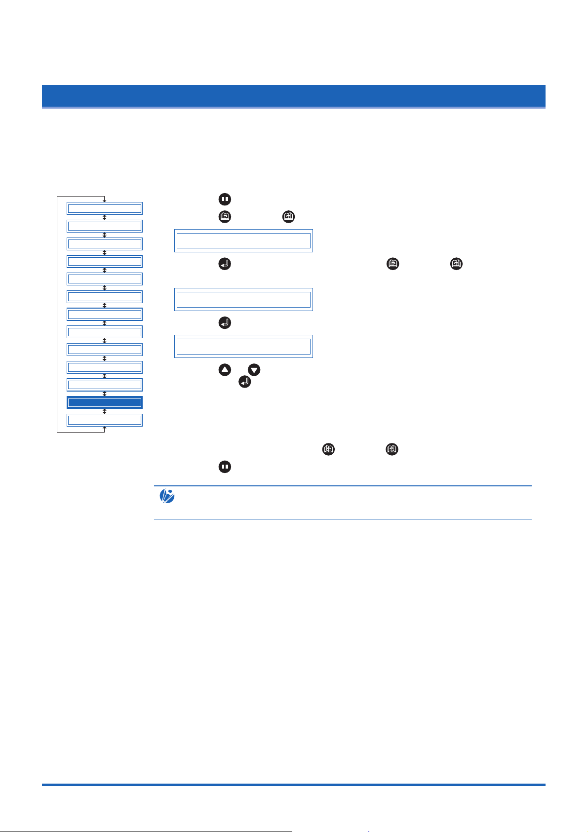
Function Settings and Operations
4.31 Setting the SEPARATOR Function
The SEPARATOR function specifies a command for use as the separator. While receiving data from the
computer, the cutting plotter considers the receipt of the command specified by the SEPARATOR setting as
an indication that a complete set of data has been sent. After plotting all of the data received prior to receipt
of such command, the cutting plotter performs cross-cutting of the medium.
CLEAR BUFFER
FEED&CUT
BLADE WARE SETUP
PEN UP/DOWN
CUT LINE PAT.
TANGENTIAL
INIT. B
PEN UP SPEED
INITIAL FEED
AUTO PRE FEED
ADVANCED FUNC.
SETUP MENU
TEST
(1) Press the (PAUSE) key to switch to PAUSE mode.
(2) Press the (NEXT) or (PREV.) key until the following menu is displayed.
SETUP MENU
(3) Press the (ENTER) key, and then press the (NEXT) or (PREV .) key
until the following menu is displayed.
SEPARATOR
(4) Press the (ENTER) key to display the SEPARATOR setting.
SEPARATOR =
Press the or key to specify one of the available SEPARATOR settings and
then press the (ENTER) key.
GP-GL command mode:
"FS", "H", "J0", "F", "(blank)"
HP-GL command mode:
"IN", "DF", "PS", "IW", "SC", "IP", "SP", "NR", "PG", "AH", "AF", "(blank)"
To cancel the selection, press the (NEXT) or (PREV.) key.
(5) Press the (PAUSE) key to cancel PAUSE mode.
CHECKPOINT
The setting is retained in the internal memory even when the power is turned off.
4-36
Page 84

Function Settings and Operations
4.32 Setting the TIMEOUT Function
When data is being input to the cutting plotter via the interface, the cutting plotter considers any pause in
data transmission that is equal to or longer than the specified TIMEOUT interval as a indication that a
complete set of data has been sent and performs cross-cutting of the medium.
CLEAR BUFFER
FEED&CUT
BLADE WARE SETUP
PEN UP/DOWN
CUT LINE PAT.
TANGENTIAL
INIT. B
PEN UP SPEED
INITIAL FEED
AUTO PRE FEED
ADVANCED FUNC.
SETUP MENU
TEST
(1) Press the (PAUSE) key to switch to PAUSE mode.
(2) Press the (NEXT) or (PREV.) key until the following menu is displayed.
SETUP MENU
(3) Press the (ENTER) key, and then press the (NEXT) or (PREV .) key
until the following menu is displayed.
TIMEOUT
(4) Press the (ENTER) key to display the TIMEOUT setting.
TIMEOUT = 0
Press the or key to specify one of the available TIMEOUT settings and
then press the (ENTER) key.
"0", "1", "2", "3", "5", "10", "20", "30", "60", "120" (seconds)
To cancel the selection, press the (NEXT) or (PREV.) key.
(5) Press the (PAUSE) key to cancel PAUSE mode.
CHECKPOINT
• The setting is retained in the internal memory even when the power is turned off.
• If “0” has been selected, the TIMEOUT function is disabled.
4-37
Page 85

Function Settings and Operations
4.33 Setting the PAPER READY TIME
This function is used to set the length of time required for a medium that has been pulled out from a roll to
become acclimated to the operating environment in order to prevent adverse cutting or plotting results due to
medium expansion or contraction.
After the medium feed operation has been completed ("4.10 Setting the INITIAL FEED Length"), rewind half
of the medium length that was fed ("4.30 Setting the PAGE LENGTH"), and then leave it for the specified
length of time to allow it to become acclimated to the environment.
This setting becomes effective when ON has been selected for the INITIAL FEED setting.
CLEAR BUFFER
FEED&CUT
BLADE WARE SETUP
PEN UP/DOWN
CUT LINE PAT.
TANGENTIAL
INIT. B
PEN UP SPEED
INITIAL FEED
AUTO PRE FEED
ADVANCED FUNC.
SETUP MENU
TEST
(1) Press the (PAUSE) key to switch to PAUSE mode.
(2) Press the (NEXT) or (PREV.) key until the following menu is displayed.
SETUP MENU
(3) Press the (ENTER) key, and then press the (NEXT) or (PREV .) key
until the following menu is displayed.
PAPER READY TIME
(4) Press the (ENTER) key to display the PAPER READY TIME setting.
UNTIL 0sec
Press the or key to specify one of the available PAPER READY TIME
settings, and then press the (ENTER) key.
"0", "60", "120", "180", "300", "420", "600" (seconds)
To cancel the selection, press the (NEXT) or (PREV.) key.
(5) Press the (PAUSE) key to cancel PAUSE mode.
CHECKPOINT
• The setting is retained in the internal memory even when the power is turned off.
• If a PAPER READY TIME setting has been specified, the amount of time remaining
(countdown time) is displayed on the LCD.
4-38
UNTIL 15sec
• Plotting or cutting of data that has been sent to the plotter during the PAPER READY
TIME operation is performed immediately after the PAPER READY TIME and PAPER
LOAD operations have been completed ("4.34 Setting the PAPER LOAD Function").
• If the
(NEXT) or (PREV.) key is pressed during a PAPER READY TIME
operation, the plotter immediately aborts the PAPER READY TIME operation and starts
the PAPER LOAD operation ("4.34 Setting the PAPER LOAD Function").
Page 86

Function Settings and Operations
4.34 Setting the PAPER LOAD Function
This function is used to set the number of pre-feed operations (an operation that leaves traces of the grit
rollers on a medium to prevent it from slipping during a cutting or plotting operation) to be performed on a
length of medium that has been pulled out from a roll.
The pre-feed function is performed repeatedly for the specified number of times after the PAPER READY
TIME ("4.33 Setting the PAPER READY TIME") operation has been completed.
This setting becomes effective when ON has been selected for the INITIAL FEED setting.
CLEAR BUFFER
FEED&CUT
BLADE WARE SETUP
PEN UP/DOWN
CUT LINE PAT.
TANGENTIAL
INIT. B
PEN UP SPEED
INITIAL FEED
AUTO PRE FEED
ADVANCED FUNC.
SETUP MENU
TEST
(1) Press the (PAUSE) key to switch to PAUSE mode.
(2) Press the (NEXT) or (PREV.) key until the following menu is displayed.
SETUP MENU
(3) Press the (ENTER) key, and then press the (NEXT) or (PREV .) key
until the following menu is displayed.
PAPER LOAD
(4) Press the (ENTER) key to display the PAPER LOAD setting.
PAPER LOAD 0
Press the or key to specify the number of pre-feed operations in the
range from "0" to "5", and then press the (ENTER) key.
To cancel the selection, press the (NEXT) or (PREV.) key.
(5) Press the (PAUSE) key to cancel PAUSE mode.
CHECKPOINT
• The setting is retained in the internal memory even when the power is turned off.
• Plotting or cutting of data that has been sent to the plotter during the PAPER READY
TIME operation is performed immediately after the PAPER READY TIME and PAPER
LOAD operations have been completed.
4-39
Page 87

Function Settings and Operations
4.35 TEST Mode
The cutting plotter has four test modes: "Condition print" (COND. PAT.) for the printing of setting details,
"Self-test" for checking accuracy, "Dump mode" for checking data transfers from the computer, and
"Cutting demo" (CUT. DEMO) for the cutting of a demo pattern. These should be used to check the various
settings and to check for problems.
CLEAR BUFFER
FEED&CUT
BLADE WARE SETUP
PEN UP/DOWN
CUT LINE PAT.
TANGENTIAL
INIT. B
PEN UP SPEED
INITIAL FEED
AUTO PRE FEED
ADVANCED FUNC.
SETUP MENU
TEST
Condition-List Printing
This function prints out the setting details currently in use.
(1) Mount a plotting pen in the pen carriage, and set the conditions to suit the pen
used (e.g., force, pen speed settings). Please see Section 3.1 "Setting the Cutter
Pen Conditions".
(2) Load an A3-size or larger medium.
If two A4 sheets are loaded side-by-side in portrait orientation, printing is
performed across the width of both sheets.
(3) Press the (PAUSE) key to switch to PAUSE mode.
(4) Press the (NEXT) or (PREV.) key until the following menu is displayed.
TEST
(5) Press the (ENTER) key to display the test-mode submenu.
COND. PAT.
(6) Press the (ENTER) key to start printing the condition list.
CAUTION
The pen carriage begins moving as soon as this function is set. Keep your hands and
other objects away from the cutting plotter's moving parts.
Self-Test-Pattern Printing
This function prints out a self-test pattern to check the accuracy of the cutting plotter.
(1) Mount a plotting pen in the pen carriage, and set the conditions to suit the pen
used (e.g., force, pen speed settings). Please see Section 3.1 "Setting the Cutter
Pen Conditions".
(2) Load an A3-size or larger medium.
(3) Press the (PAUSE) key to switch to PAUSE mode.
(4) Press the (NEXT) or (PREV.) key until the following menu is displayed.
TEST MODE
(5) Press the (ENTER) key to display the test-mode submenu, and then press
the (NEXT) or (PREV.) key until the following menu is displayed.
SELF TEST
(6) Press the (ENTER) key to start printing the self-test pattern.
(7) When the self-test pattern has been printed, turn the power off and then on again.
CAUTION
The pen carriage begins moving as soon as this function is set. Keep your hands and
other objects away from the cutting plotter's moving parts.
4-40
Page 88

Function Settings and Operations
Dump Mode
This function checks whether data is sent correctly from the computer. If the output
data does not match the program after the dump list has been output, check the
transfer conditions and connections.
(1) Mount a plotting pen in the pen carriage, and set the conditions to suit the pen
used (e.g., force, pen speed settings). Please see Section 3.1 "Setting the Cutter
Pen Conditions".
(2) Load an A4-size or larger medium.
(3) Press the (PAUSE) key to switch to PAUSE mode.
(4) Press the (NEXT) or (PREV.) key until the following menu is displayed.
TEST MODE
(5) Press the (ENTER) key to display the test-mode submenu, and then press
the (NEXT) or (PREV.) key until the following menu is displayed.
DUMP
(6) Press the (ENTER) key to switch to dump mode.
CHAR DUMP MODE
(7) When data is sent to the cutting plotter in this mode, a dump list is printed out. To
exit the dump mode, turn on the power again.
CHECKPOINT
The dump list is printed out as ASCII character codes. Characters without codes will be
printed as small 2-digit figures. Output data for READ-type commands will be output as
dummy data, except for cutting-plotter status output.
CAUTION
The pen carriage begins moving as soon as this function is set. Keep your hands and
other objects away from the cutting plotter's moving parts.
Cutting Demo
This function cuts a cutting-demo pattern.
(1) Mount a plotting pen in the pen carriage, and set the conditions to suit the pen
used (e.g., force, pen speed settings). Please see Section 3.1 "Setting the Cutter
Pen Conditions".
(2) Load a film for cutting.
(3) Press the (PAUSE) key to switch to PAUSE mode.
(4) Press the (NEXT) or (PREV.) key until the following menu is displayed.
TEST MODE
(5) Press the (ENTER) key to display the test-mode submenu, and then press
the ( (NEXT) or (PREV.) key until the following menu is displayed.
CUT DEMO
(6) Press the (ENTER) key to start cutting the demo pattern.
CAUTION
The pen carriage begins moving as soon as this function is set. Keep your hands and
other objects away from the cutting plotter's moving parts.
4-41
Page 89

CHAPTER 5
Setting and Using the Special Functions
5.1 Description of Special Functions A
5.2 Setting Special Functions A
5.3 Description of Special Functions B
5.4 Setting Special Functions B
Page 90

Setting and Using the Special Functions
5.1 Description of Special Functions A
The cutting plotter is provided with the special functions described below. These functions are specified only
in special situations, and are not normally used.
Enabling/Disabling the ":" and ";" Commands (when the COMMAND setting is GP-GL)
This function enables or disables the ":" and ";" commands when the COMMAND setting is GP-GL.
If the first part of the data is lost, these commands may be having an adverse effect. In this case,
set this function to DISABLED
(the default setting is ENABLED).
Moving the Pen While Raised or Lowered in Response to the "W" Command (when the
COMMAND setting is GP-GL)
This function selects whether, upon receipt of the "W" command for the drawing of arcs, the cutting
plotter moves the pen to the specified starting position, raised or in the pen status (raised or
lowered) that was in effect immediately prior to receipt of the "W" command.
When PEN DOWN is selected, the pen is moved to the starting position for the drawing of arcs in
the pen status (raised or lowered) that was in effect immediately prior to receipt of the "W"
command.
When PEN UP is selected, the pen is moved to the starting position for the drawing of arcs in the
raised status. This setting is only effective if a cutter blade has been selected in the cutter-pen
settings.
(The default setting is PEN UP.)
Model ID Response (when the COMMAND setting is HP-GL)
This function sets the response to the "OI" command when the COMMAND setting is HP-GL.
When 7550 is set, the "OI" command response is 7550.
When 7586 is set, the "OI" command response is 7586.
(The default setting is 7586.)
SETTING PRIORITY
This function sets whether the cutting plotter places priority on the cutting conditions specified
through command input from the computer or through manual settings (on the cutting-plotter
control panel).
When MANUAL is selected, cutting is performed using the cutting conditions set at the control
panel, and cutting conditions sent from the computer are ignored.
When COMD is selected, cutting is performed using the cutting conditions specified in a received
cutting-condition command. If no commands are received, cutting is performed using the cutting
conditions set at the control panel.
(The default setting is COMD.)
Enabling/Disabling PEN UP MOVE
This function sets whether the pen will travel to each point specified or only from the initially
specified point to the last specified point when consecutive commands are received specifying pen
movement while it is raised.
When ENABLED is selected, the pen travels consecutively to each coordinate specified by the data
received.
When DISABLED is selected, the pen travels directly from the initially specified point to the last
specified point.
(The default setting is DISABLED.)
5-2
Page 91

Setting and Using the Special Functions
Enabling/Disabling the Media Sensors
This function sets the media sensors that detect the size of the medium in the feed direction.
When ENABLED is selected, the feed-direction media sensors are enabled.
When DISABLED is selected, the feed-direction media sensors are disabled.
(The default setting is ENABLED.)
Enabling/Disabling the Home Sensors
This function sets the home sensors that detect the width of the medium.
When ENABLED is selected, the home sensors are enabled.
When DISABLED is selected, the home sensors are disabled.
(The default setting is ENABLED.)
Circle-Command Resolution Setting (when the COMMAND setting is HP-GL)
This function sets whether the resolution is automatically set or fixed at a constant 5 degrees when
a cutting-plotter circle command is output while the COMMAND setting is HP-GL.
(The default setting is DEFAULT.)
Enabling/Disabling Blade Wear Detection
When ENABLED is selected, the blade wear-detection setting is enabled and the blade weardetection setting menu is displayed in the PAUSE menu.
When DISABLED is selected, the blade wear-detection setting is disabled, and the blade weardetection setting menu is removed from the PAUSE menu and is not displayed. For details on wear
detection, refer to see "4.4 Blade Wear Detection."
(The default setting is DISABLED.)
Setting the Cross-Cut Force
The cross-cut force can be set in the range "1" to "31".
(The default value is 20)
PAUSE Key Setting
Selects the screen to be displayed when you press the (PAUSE) key while cutting or plotting.
If you serect "HOLD" the cutting plotter stops cutting or plotting and displays a jobselect screen
prompting you to choose to continue or stop cutting/plotting.
If you serect "MENU" the cutting plotter stops cutting or plotting and displays a pause menu screen.
(The default setting is MENU)
CHECKPOINT
If the media or home sensors have been disabled (set to OFF), be sure to specify the cutting/plotting
area (see "4.14 Setting the Cutting/Plotting Area"). If the cutting/plotting area is not specified, the
cutting mat may be damaged.
5-3
Page 92
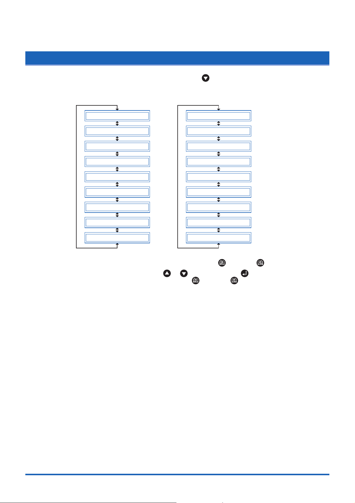
Setting and Using the Special Functions
5.2 Setting Special Functions A
(1) Turn on the cutting plotter while holding down the key. The menus for setting the special
functions are displayed.
In GP-GL command mode In HP-GL command mode
“:”, “:” ENABLED
“W” PEN UP
PRIORITY COMD
UP MODE DISABLED
MEDIA ENABLED
HOME ENABLED
B.W.S. DISABLED
CROSSCUT FORCE20
PAUSE KEY MENU
MODEL 7586
PRIORITY COMD
UP MODE DISABLED
MEDIA ENABLED
HOME ENABLED
CIRCLE DEFAULT
B.W.S. DISABLED
CROSSCUT FORCE20
PAUSE KEY MENU
(2) Scroll up or down to select the required menu using the (NEXT) or (PREV.) key.
(3) Select the setting details using the or key, and press the (ENTER) key to register
the setting. To cancel the selection, press the (NEXT) or (PREV.) key. The next menu
is displayed.
(4) Once all the settings have been made, turn off the cutting plotter.
5-4
Page 93

Setting and Using the Special Functions
5.3 Description of Special Functions B
These functions are specified only in the special situations described below, and are not normally used.
Display Language Setting (MENU LANGUAGE SELECTION)
This function sets the language used on the display. One of six languages can be selected: English,
French, German, Italian, Spanish, or Japanese.
5.4 Setting Special Functions B
(1) Turn the cutting plotter on while holding down the (ENTER) and (ORIGIN) keys
simultaneously. The special functions B setting menu is displayed.
DISPLAY ENGLISH
(2) Use the or key to select the desired display language, and then press the (ENTER)
key to confirm. To cancel the selection, press the (NEXT) or (PREV.) key.
(3) Once all the settings have been made, turn off the cutting plotter.
5-5
Page 94

CHAPTER 6
Troubleshooting
6.1 The Cutting Plotter Does Not Operate When Turned On
6.2 The Cutting Plotter Does Not Operate Correctly
6.3 The Cutting Results Are Unsatisfactory
6.4 An Error Message Was Displayed
Page 95

Troubleshooting
6.1
The Cutting Plotter Does Not Operate When Turned On
Symptom
The STATUS lamp on the
control panel does not light
up.
The STATUS lamp on the
control panel lights up, but
nothing appears on the
display panel.
Power is not being fed to the cutting
plotter.
The cutting plotter is defective.
Cause
Solution
Check to confirm that the power cord
is securely connected to the cuttingplotter AC line inlet and the electrical
outlet.
Contact your sales representative or
nearest Graphtec dealer.
6.2 The Cutting Plotter Does Not Operate Correctly
Symptom
OFFSCALE is displayed
when data is received.
Some areas cannot be cut.
Cannot maintain the cutting
conditions
Cannot change the cutting
conditions
"LOAD MEDIA" is displayed
even when the medium has
been loaded.
The medium is skewed.
The medium is suddenly fed
forward.
Abnormal noise is
generated by the cutter
during cutting.
Misaligned plotting.
The start and end points do
not meet.
Plotting and cutting are not
aligned.
The data received lies outside the
cutting/plotting area set.
The data received is larger than the
cutting/plotting area set.
The cutter-pen condition-setting
priority is set to PROGRAM.
ENTER was not pressed after the
settings were changed.
The medium is semi-transparent and
is not detected by the media sensors.
The medium is not detected by the
media sensors due to strong
reflected light.
The medium is not loaded so that it
passes the media sensors.
The right-hand pinch roller is not
positioned over the right-hand long
grit roller.
The left-hand pinch roller is not
positioned over the left-hand grit
roller.
The medium was loaded at an angle.
The length of the medium to be cut
was not drawn out first when the
medium was loaded.
The selections for medium loading
are incorrect.
The cutter plunger tip is in contact
with the medium.
The paper is not acclimated to its
environment, and therefore the paper
is expanding or contracting during
plotting or cutting.
Cause
Solution
Set the cutting/plotting area.
Check the page-length setting.
Replace with a larger-size medium.
Reduce the data size.
Set the condition setting priority to
MANUAL.
Check the operation and reset the
cutter-pen conditions.
Set the media-sensor setting to
DISABLE, and set the cutting/plotting
area.
Change the lighting direction and
avoid direct sunlight.
Load so that the medium passes over
the media sensors.
Position the right-hand pinch roller
over the right-hand long grit roller.
Position the left-hand pinch roller
over the left-hand grit roller.
Reload the medium.
Draw out the required length of roll
medium to be used.
Check the medium selection (ROLL1
PRESS ENTR, ROLL2 PRESS
ENTR, SHEET PRESS ENTR).
Adjust the cutter-blade extension.
Reduce the cutting force.
Use the "PAPER READY TIME" and
"PAPER LOAD" functions to
acclimate the paper to its
environment.
6-2
Page 96

6.3 The Cutting Results Are Unsatisfactory
Troubleshooting
Symptom
The cut corners are too
rounded or too pointed.
Only the initial section cut is
satisfactory.
Solid lines are not cut at a
constant depth (mild
skipping).
Curved lines have coarse
resolution.
Characters or complex
figures are deformed.
The cutting start and end
points for figures do not
match.
Cannot cut to the specified
size
The length cut differs from
that specified.
The medium is discolored
where the blade cut.
The cutter blade cuts into
the backing sheet.
Characters and lines are
deformed when plotted
using the pen.
Cause
The cutter offset does not match the
blade type used.
The cutter blade is not rotating
smoothly in the holder.
The offset force is insufficient.
The CB09UA spring is missing.
The blade is extended too far.
The cutting speed is too high.
The cutting data is too coarse.
The blade offset angle is too small.
The step-pass setting is too large.
The data is not connected.
The offset force is too low.
The film is too flimsy.
The cutter blade is not rotating
smoothly in the holder.
The step size for the software and the
cutting plotter do not match.
Scaling has been specified in the
software.
The medium is slipping.
The distance correction is not correct.
The cutter plunger tip is in contact
with the medium.
The blade is extended too far.
The cutting force is too high.
A blade has been selected in the
cutter-pen settings.
Solution
Adjust the cutter offset value.
Corners are rounded:
Increase the value.
Corners are pointed:
Reduce the value.
Clean inside the holder.
Increase the offset force.
Replace the blade with a spring
attached.
Adjust the blade extension length.
Reduce the cutting speed.
Correct so that the application data is
output with greater detail.
Increase the offset angle.
Reduce the step-pass setting.
Check by plotting using a pen, and
correct the data.
Increase the offset force.
Use a stiffer film.
Clean inside the holder.
Adjust the step-size settings so that
they match.
Check the scaling.
Reduce the cutting speed.
Reduce the pen-up speed.
Adjust the distance correction.
Adjust the blade extension length.
Reduce the cutting force.
Adjust the blade extension length.
Reduce the cutting force.
Select PEN.
6-3
Page 97

Troubleshooting
6.4 An Error Message Was Displayed
Symptom
CURRENT LIMIT or
POSITION ERROR is
displayed.
The POWER lamp flickers.
SPEED ERROR is
displayed.
The POWER lamp flickers.
The cutting conditions are not
suitable for the medium being cut.
Excessive load is causing the current
to the motor to exceed the rated
value.
The pen carriage movement is being
obstructed.
The pen carriage was subjected to
external pressure during cutting.
Scraps of the medium in the moving
parts are impeding operation.
The stock shaft stopper is set to the
LOCK position.
If this problem occurs frequently, contact your sales representative or
nearest Graphtec dealer.
The pen carriage was subjected to
external pressure after the power
was turned on.
The internal speed control is faulty.
If this problem occurs frequently, contact your sales representative or
nearest Graphtec dealer.
Cause
Solution
Reduce the cutting speed.
Reduce the cutting force.
Remove the obstruction and turn the
cutting plotter back on.
Set the stock shaft stopper to the
FREE position.
Turn the cutting plotter off and then
back on again.
If any of the following command error messages appear, they are nearly always caused by one of
the following two reasons:
• The software or host-computer settings have been changed.
• The cutting-plotter interface settings have been changed.
Solutions
• Configure the settings in the software menu so that the menu can control the cutting plotter.
• Set the host-computer interface conditions correctly.
• Set the cutting-plotter interface conditions correctly.
6-4
Page 98

Error messages in GP-GL command mode
Troubleshooting
Error message
GP-GL ERROR 1
GP-GL ERROR 2
GP-GL ERROR 3
GP-GL ERROR 4
GP-GL ERROR 5
Cause
An unrecognizable command was received.
Noise was received when the computer was
turned on.
The software command settings for
controlling the cutting plotter have been
changed.
The data-transmission settings have been
changed in the interface settings.
The command terminator is incorrect.
The software settings for the output device
have been changed.
The data-transmission settings have been
changed in the interface settings.
The command delimiter is incorrect.
The software settings for the output device
have been changed.
The data-transmission settings have been
changed in the interface settings.
The command parameter exceeds the
permissible range.
The software settings for the output device
have been changed.
The data-transmission settings have been
changed in the interface settings.
An error occurred in the reception of data
within the interface.
The software command settings for
controlling the cutting plotter have been
changed.
The data-transmission settings have been
changed in the interface settings.
Solution
Press the ENTER key to cancel the
error.
Set the software command settings
for controlling the cutting plotter.
Set the correct data-transmission
conditions.
Set the software command settings
for controlling the cutting plotter.
Set the correct data-transmission
conditions.
Set the software command settings
for controlling the cutting plotter.
Set the correct data-transmission
conditions.
Set the software command settings
for controlling the cutting plotter.
Set the correct data-transmission
conditions.
Set the software command settings
for controlling the cutting plotter.
Set the correct data-transmission
conditions.
6-5
Page 99

Troubleshooting
Error messages in HP-GL command mode
Error message
HP-GL ERROR 1
HP-GL ERROR 2
HP-GL ERROR 3
HP-GL ERROR 5
HP-GL ERROR 6
HP-GL ERROR 7
HP-GL ERROR 10
Cause
An unrecognizable command was received.
Noise was received when the computer was
turned on.
The software command settings for
controlling the cutting plotter have been
changed.
The data-transmission settings have been
changed in the interface settings.
The command was executed with the wrong
parameters.
The software settings for the output device
have been changed.
The data-transmission settings have been
changed in the interface settings.
The command parameter is incorrect.
The software settings for the output device
have been changed.
An unrecognizable character set was
specified.
The software settings for the output device
have been changed.
The command coordinates specified are
outside the cutting/plotting area.
The software settings for the output device
have been changed.
The buffer overflowed when the
downloadable-character buffer or polygon
buffer was used.
The software settings for the output device
have been changed.
Another output command was executed
while a command was already being
executed.
An invalid command was received following
an ESC code.
An invalid byte was received within a device
control command.
A parameter outside the permissible range
was speci-fied in an I/O command.
There were too many parameters in an I/O
command.
A framing error, parity error, or overrun error
occurred.
The interface buffer overflowed.
Solution
Press the ENTER key to cancel the
error.
Set the software command settings
for controlling the cutting plotter.
Set the correct data-transmission
conditions.
Set the software command settings
for controlling the cutting plotter.
Set the correct data-transmission
conditions.
Set the software command settings
for controlling the cutting plotter.
Set the software command settings
for controlling the cutting plotter.
Set the software command settings
for controlling the cutting plotter.
Set the software command settings
for controlling the cutting plotter.
Set the software command settings
for controlling the cutting plotter.
Set the correct data-transmission
conditions.
6-6
Page 100

Appendix
Appendix A Main Specifications
Appendix B Options and Supplies
Appendix C External Dimensions
Appendix D Menu Tree
 Loading...