

Page 1

Advantage M8
Card Printer & Embosser
Operation Manual
MANUAL NO. Advantage M8-UM-153
NBS Technologies Inc.
Page 2
y
y
Essential Safety Precautions
This operating manual provides the safety precautions and the handling methods required to use the
product. Before using this machine, be sure to read this operating manual for safe and proper
operation. After reading, keep it in a safe place for later reference.
For any questions, contact your distributor.
z This product is designed to emboss/encode/print specified plastic cards. Do not use this for
any other application purposes.
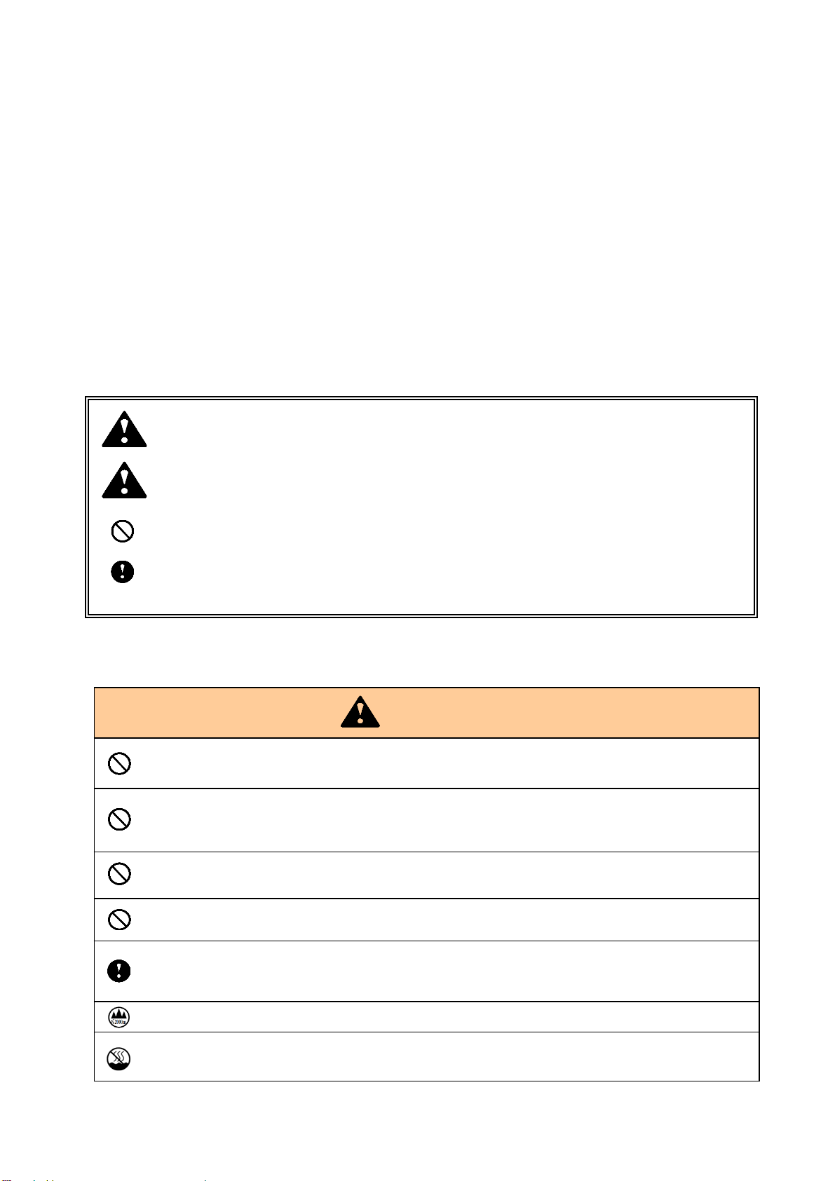
z In this operating manual, items to be especially observed are marked with signs or symbols
for safe and proper use of the product. As they are important contents, be sure to observe
and follow them.
Warning Improper handling may cause death or severe injury.
Caution Improper handling may cause injury or property damage.
Never do this.
Be sure to follow instructions.
Product Handling
Do not overload one electrical outlet by using a power strip and multi-outlet adapter.
It may cause electric shock or fire.
Do not disassemble or modify. It may cause an electric shock or fire.
If it is necessary to remove a cover for maintenance, inspection, cleaning, or repair,
contact your distributor.
Only use with rated voltage and the rated frequency.
Failure to do so may cause an electric shock or fire.
Do not use a damaged power cord or loose outlet.
cause an electric shock or fire.
It ma
Check that the power plug does not have dust before inserting it into the outlet. Every six
months to one year, pull the power plug out of the outlet and inspect the plug for
cleanliness. Dust ma
Used only at altitudes not more than 2000m above sea level.
Used only in non-tropical conditions. (Operating environment Temperature 10 to 32
degrees Celsius/ Humidity 20 to 65% R.H (non-condensing))
Warning
cause an electric shock or fire.
Page 3
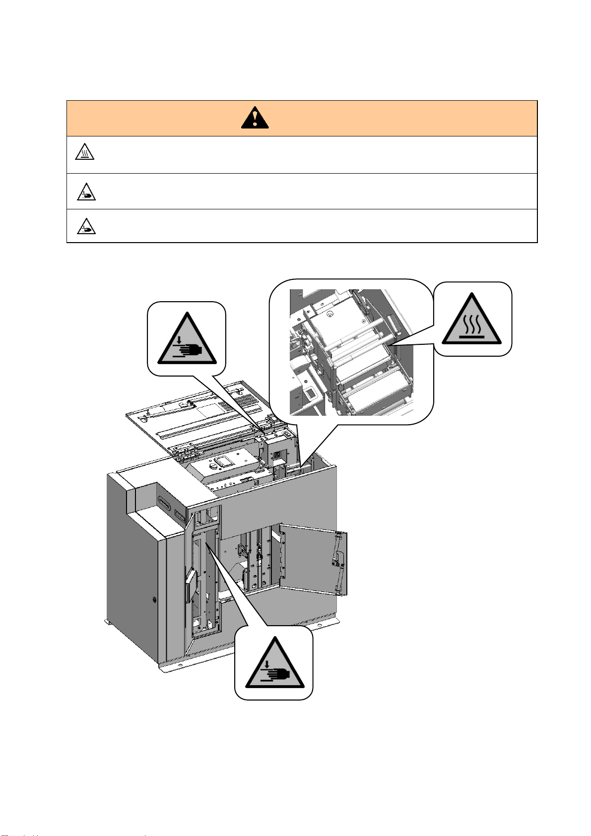
Continued from Product Handling
The Tipper Unit might be hot. To reduce the risk of injury from the heat,
allow the Tipper Unit to cool before touching.
Please take care not to get your hand or finger caught, when you open and close
the upper
Please take care not to get your hand or finger caught in the moving units, when you take
out remaining card or conduct maintenance work. It may cause an injury.
Warning
Page 4
p
Continued from Product Handling
Do not use a card contaminated with dirt or flaws.
It may cause a breakdown.
Do not wipe with benzene, solvents or thinner. It may cause discoloration or deformation
of this machine. For heavy contaminents, apply dilute mild detergent to a cloth, wring it
thoroughly, then wipe off the contaminents with it, finally wipe with a dry, soft cloth.
Never open the covers of this machine during operation.
It may cause injury.
When not using for a long period, be sure to pull the power plug out of the outlet.
Failure to do so may cause a fire.
When pulling out the power plug, hold the tip of the power plug.
Failure to do so may cause an electric shock.
Product Installation
Avoid installing in direct sunlight or near to a bright light source or a window.
It may interfere with proper operation.
Avoid installing in a place with extremely high temperatures/humidity or a place with rapid
humidity changes. It may cause condensation, resulting in a breakdown or improper
eration.
o
Avoid installing in a dusty place.
It may cause a breakdown.
Avoid installing in a place with heavy vibration.
It may interfere with proper operation.
Avoid installing in a place with an unstable base or a where the surface is not flat place.
It may interfere with proper operation or fall, resulting in injury.
Power supply connection of this product should be done by a technician with necessary
knowledge and qualification. It may cause electric shock or fire.
Ensure a good electrical ground is established.
Failure to do so may cause an electric shock.
Do not insert the power plug into the outlet until the connection is completed.
Only connect cables when the host computer and this machine are turned off.
LAN connector and USB connector are sensitive to ESD.
Connect these communication cables when the machine is powered off.
Caution
Caution
Page 5
y
y
Continued from Product Installation
Power supply connection of this product should be done by a technician with necessary
knowledge and qualification. It may cause electric shock or fire.
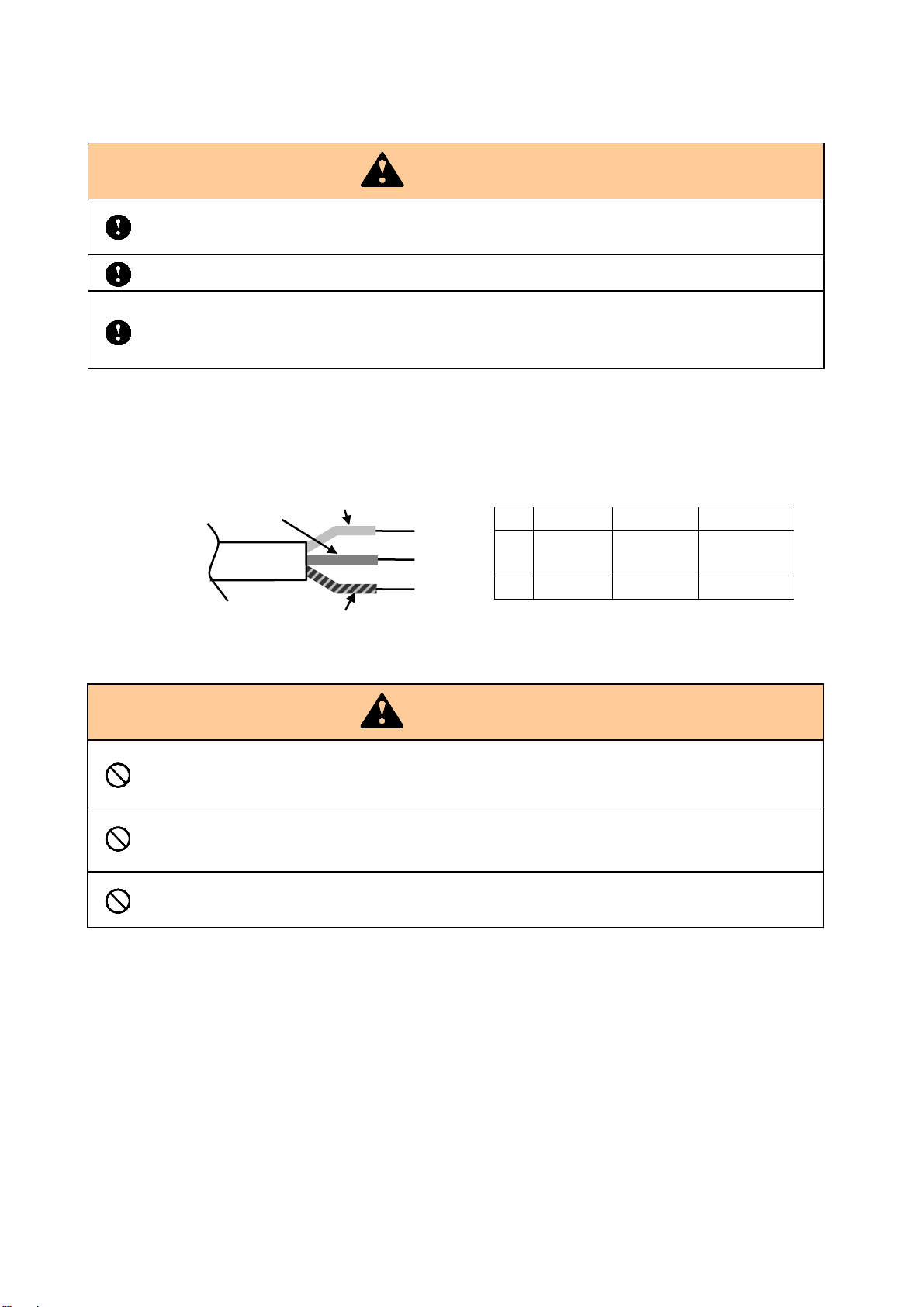
Connect the supplied power cord to the inlet on the back.
Connect the end of the power cord to the switchboard and use it, or use an appropriate plug to install it.
Plug is not included. Please prepare separately the plug which satisfies the laws and regulations of the
country/region where this product is installed.
Card Handling
When connecting a cable, be sure to insert it as far as it will go and lock if a lock function is
equipped.
Install in a place more than 10 cm away from the side wall.
Use the supplied power cord only for this machine.
N
When you are touching the cards, it is recommendable for you to wear gloves. If finger
prints contaminate the surface of the card, it may cause bad print quality. To carry a card it
is recommended that it is held b
Do not put or store cards in a dusty place, a place with high temperatures or near electric
appliances that may emit a strong magnetic field (such as a mobile phone and monitor). It
cause deformation of cards or deletion of magnetic data.
ma
Do not bend the cards or damage the magnetic strip. It may interfere with proper reading
of magnetic information.
Caution
L
GND
The wire covering color is either 1 or 2.
Caution
its edges.
L N GND
1 Brown Blue
2 Black White Green
Green/
Yellow
Page 6

Federal Communications Commission (FCC)
Statement
This equipment has been tested and found to comply with the limits for a Class A digital device, pursuant to
Part 15 of the FCC Rules. These limits are designed to provide reasonable protection against harmful
interference when the equipment is operated in a commercial environment. This equipment generates,
uses, and can radiate radio frequency energy and, if not installed and used in accordance with the
instruction manual, may cause harmful interference to radio communications. Operation of this equipment
in a residential area is likely to cause harmful interference, in which case the user will be required to correct
the interference at his own expense.
Caution
Changes or modifications not expressly approved by the party responsible for compliance could void the
user's authority to operate this equipment.
This transmitter must not be co-located or operating in conjunction with any other antenna or transmitter.
Industry Canada(IC)
Statement
This device contains license-exempt transmitter(s)/ receiver(s) that comply with Innovation, Science and
Economic Development Canada’s licence-exempt RSS(s). Operation is subject to the following two
conditions:
(1) This device may not cause interference.
(2) This device must accept any interference, including interference that may cause undesired operation of
the device.
L’émetteur/récepteur exempt de licence contenu dans le présent appareil est conforme aux CNR
d’Innovation, Sciences et Développement économique Canada applicables aux appareils radio exempts de
licence. L’exploitation est autorisée aux deux conditions suivantes :
1. L’appareil ne doit pas produire de brouillage;
2. L’appareil doit accepter tout brouillage radioélectrique subi, même si le brouillage est susceptible d’en
compromettre le fonctionnement.
Caution:
Exposure to Radio Frequency Radiation. The installer of this radio equipment must ensure that the antenna
is located or pointed such that it does not emit RF field in excess of Health Canada limits for the general
population; consult Safety Code 6, obtainable from Health Canada’s website www.hc-sc.gc.ca.
Exposition à des radiations de fréquences radio. Cet appareil émettant des ondes radio, l'installateur doit
s'assurer que l'antenne est positionnée ou orientée de telle sorte que l'appareil émette des champs RF ne
dépassant pas les limites recommandées par Santé Canada pour le grand public; consultez Code de
sécurité 6, disponible à Santé Canada ou sur leur site web www.hc-sc.gc.ca.
Page 7

Table of contents
Essential Safety Precautions
Product Handling
Product Installation
Card Handling
Contents of the package ············································································································ 1
Name of Each Part ··················································································································· 2
Front ·································································································································· 2
Back ·································································································································· 2
Inside of Front Cover ············································································································· 3
Inside of Top Cover ··············································································································· 3
Inside of Right side door ········································································································· 4
Preparation before Use ············································································································· 5
Installation and connection of the main body ·············································································· 5
Card setting ························································································································· 6
How to use the machine ·········································································································· 10
Setting and Checking the IP Address ······················································································ 10
Card Issuing ······················································································································ 1 1
Exchange of Thermal Transfer Ribbon ···················································································· 12
Exchanging Tipper Foil ········································································································ 14
Exchanging Indent Film ········································································································ 18
Picking up cards from Output Stacker ····················································································· 21
Picking up cards from Reject Stacker ······················································································ 22
Eco mode ·························································································································· 23
Error Message ······················································································································ 24
Error during standby ············································································································ 24
Consumable error ··············································································································· 25
Error during operation ·········································································································· 26
Error and warning during printing or encoding operation ····························································· 28
Error Reset ··························································································································· 30
Removing the card remaining in Input Hopper ·········································································· 30
Removing the card remaining in Main Transfer Unit ··································································· 32
Removing the card remaining in Print /Encode Unit ··································································· 35
Removing the card remaining in Vertical Rotation Unit ································································ 39
Removing the card remaining in Carriage Unit ·········································································· 40
Removing the card remaining in Emboss Unit ··········································································· 42
Removing the card remaining in Card Insertion/Exit Slot ····························································· 45
Cleaning ······························································································································ 46
Cleaning Thermal Print Head ································································································ 46
Washing Cleaning Roller ······································································································ 49
Cleaning Card transfer rollers ································································································ 52
Specifications ························································································································ 54
General Specifications ········································································································· 54
Embosser Specifications ······································································································ 55
Encoder Specifications ········································································································· 55
Printer Specifications ··········································································································· 55
Restriction of Usable card ····································································································· 55
User environment ··············································································································· 56
Page 8
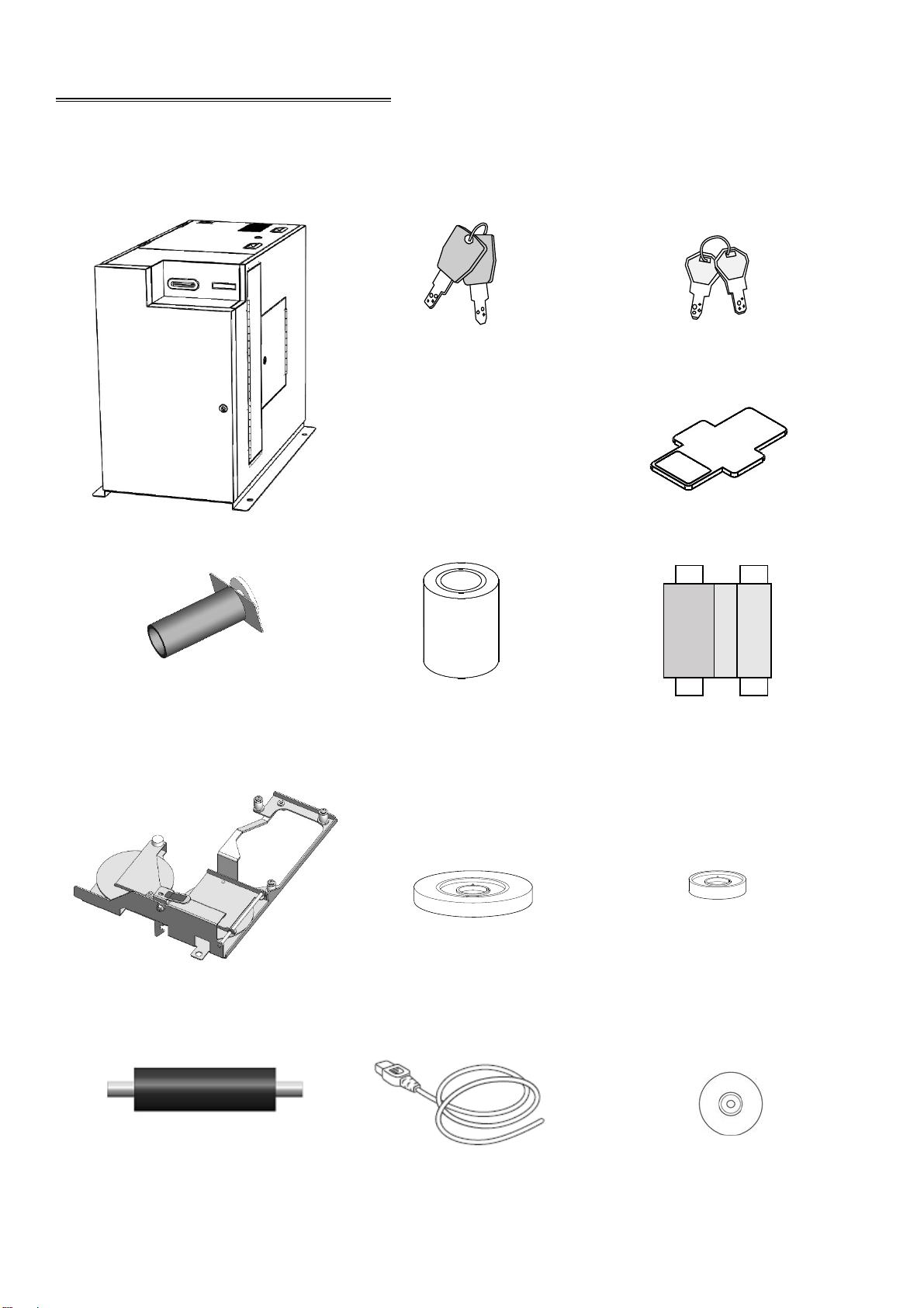
Contents of the package
The package contains the following items.
(Please contact your dealer if you cannot find anything.)
Cover key (2 pieces x 3) Cassette key (2 pieces x 2)
Main Body Weight (6 pieces)
Reel hardware for tipper Tipper Foil Thermal Transfer Ribbon
(with paper core)
Indent Cassette Indent film Indent film empty core
Cleaning Roller Power cable CD (Operation Manual (pdf))
.
1
Page 9
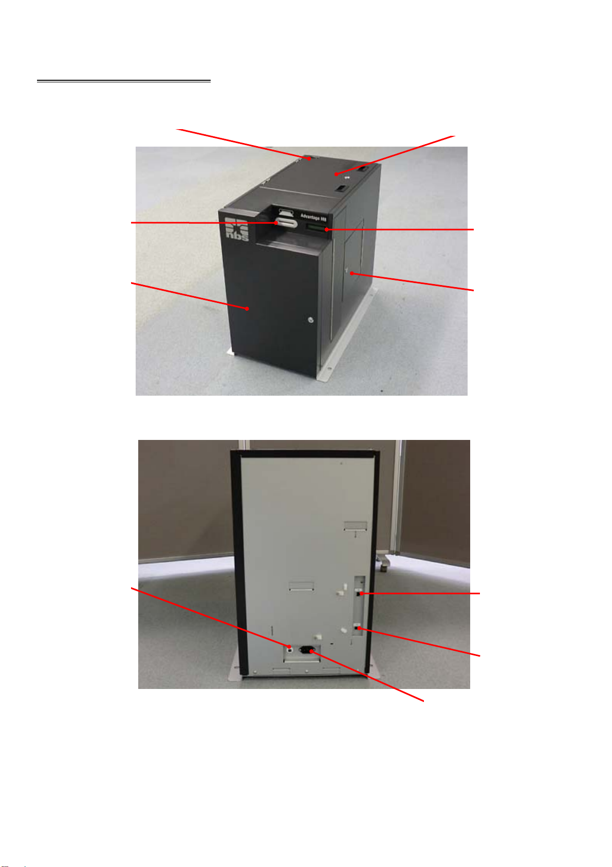
Name of Each Part
Front
Card
Insertion /Exit
Slot
Front Cover
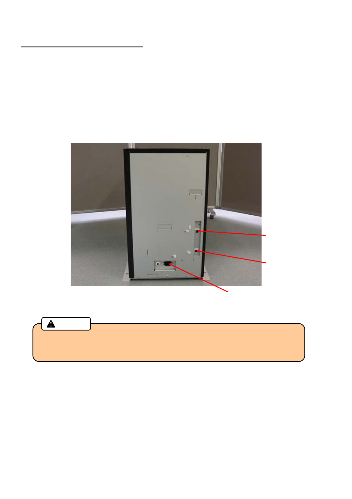
Back
Circuit
Breaker
Power Switch
Top Cover
Main display
Right side door
LAN
Connector
USB
Connector
AC Inlet
2
Page 10
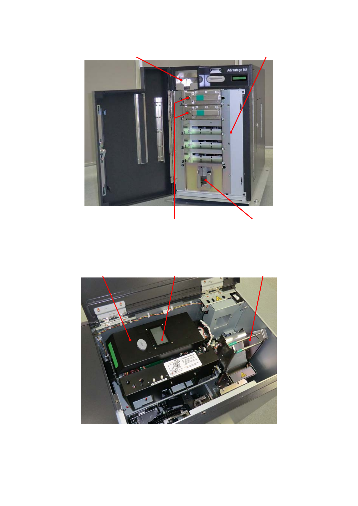
Inside of Front Cover
Output Stacker Unit
Input Hopper
Inside of Top Cover
Print /Encode Unit
Hopper Cassettes
Print /Encode Unit display
Reject Stacker Unit
Tipper Unit
3
Page 11
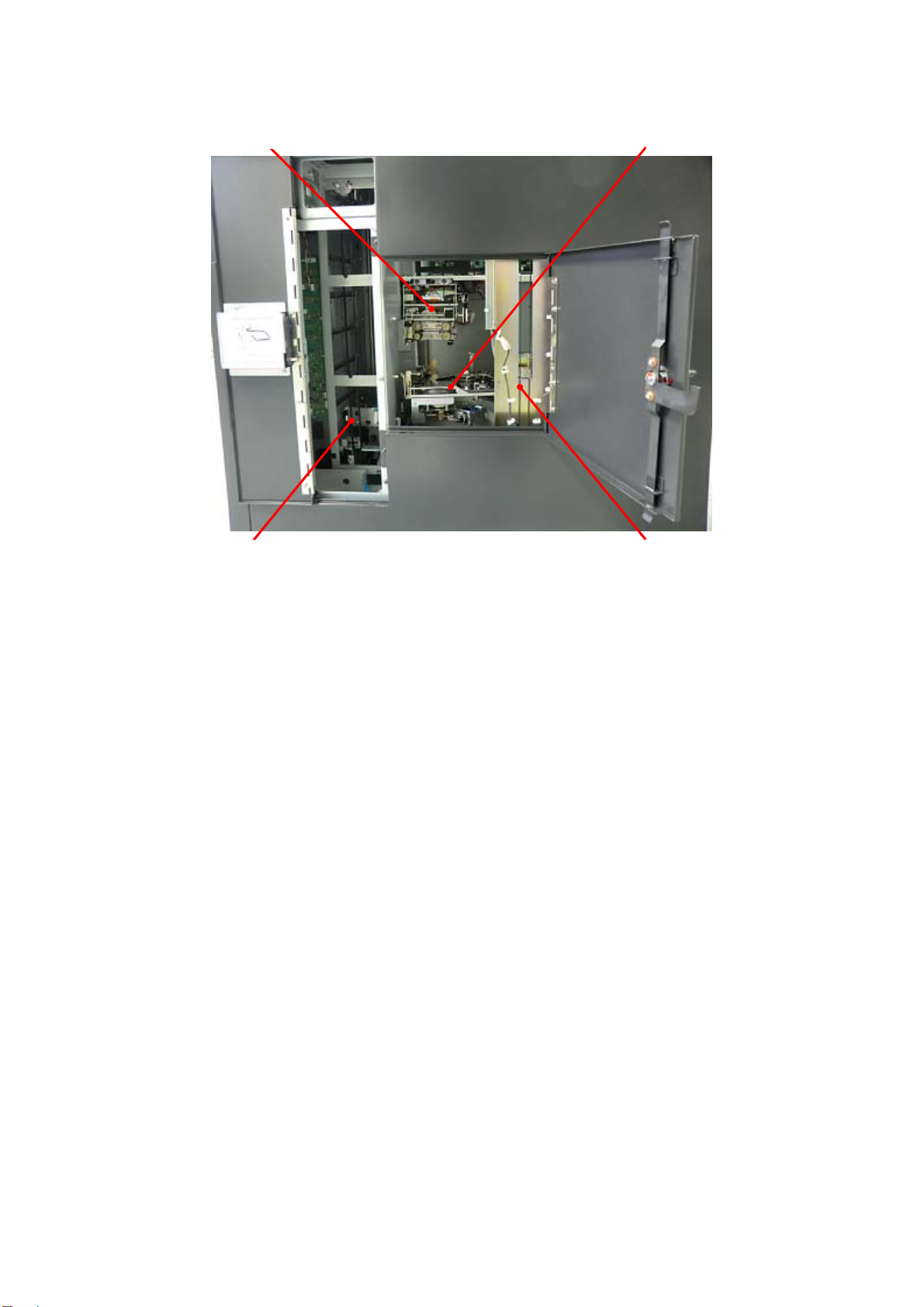
Inside of Right side door
Vertical Rotation unit
Emboss Unit
Main Transfer Unit
(* Elevator part to be
called “Carrier” in
this manual.)
Carriage Unit
(* Transfer unit to carry a card to the
Vertical Rotation unit, Emboss
Unit and Tipper Unit to be called
“Carriage” in this manual.)
4
Page 12
Preparation before Use
For installation, please read “Product Installation” in this document in advance.
Installation and connection of the main body
1. Place the main body on the installation space.
2. Install the Tipper Foil according to the procedure “Exchanging Tipper Foil” on page 14.
3. Connect the host computer and the main body with connection cable.
4. Connect the power cord to the AC inlet and AC outlet.
Caution
・ Communication connectors (LAN, USB) are very sensitive to static electricity.
You should turn off the power before you connect or remove the cables on the rear
side to protect the machine against the static electricity.
5. Install the ribbon according to the procedure “Exchange of Thermal Transfer Ribbon” on page 12.
AC Inlet
LAN
Connector
USB
Connector
5
Page 13
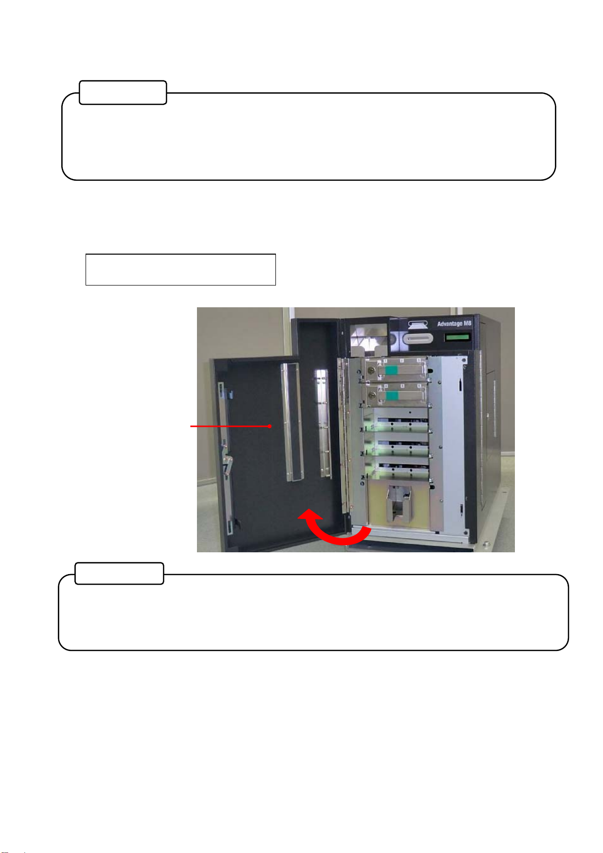
Card setting
Reference
• Front Cover of the main body can only be opened by unlocking both the physical cover
key and electrical lock.
• For unlocking the electrical lock, you need to connect a LAN cable and run application
software.
1. Turn the power ON.
Unlock the Front cover with the application software and the key turning clockwise. When the Front
Cover is opened, the buzzer will beep, and the following error message will be indicated on the Main
display.
CV401 Front
Reference
• After unlocking the electrical lock, the Front Cover must be opened promptly.
If the Front Cover is left closed for a while, it will be locked by the electrical lock
automatically.
Front Cover
6
Page 14
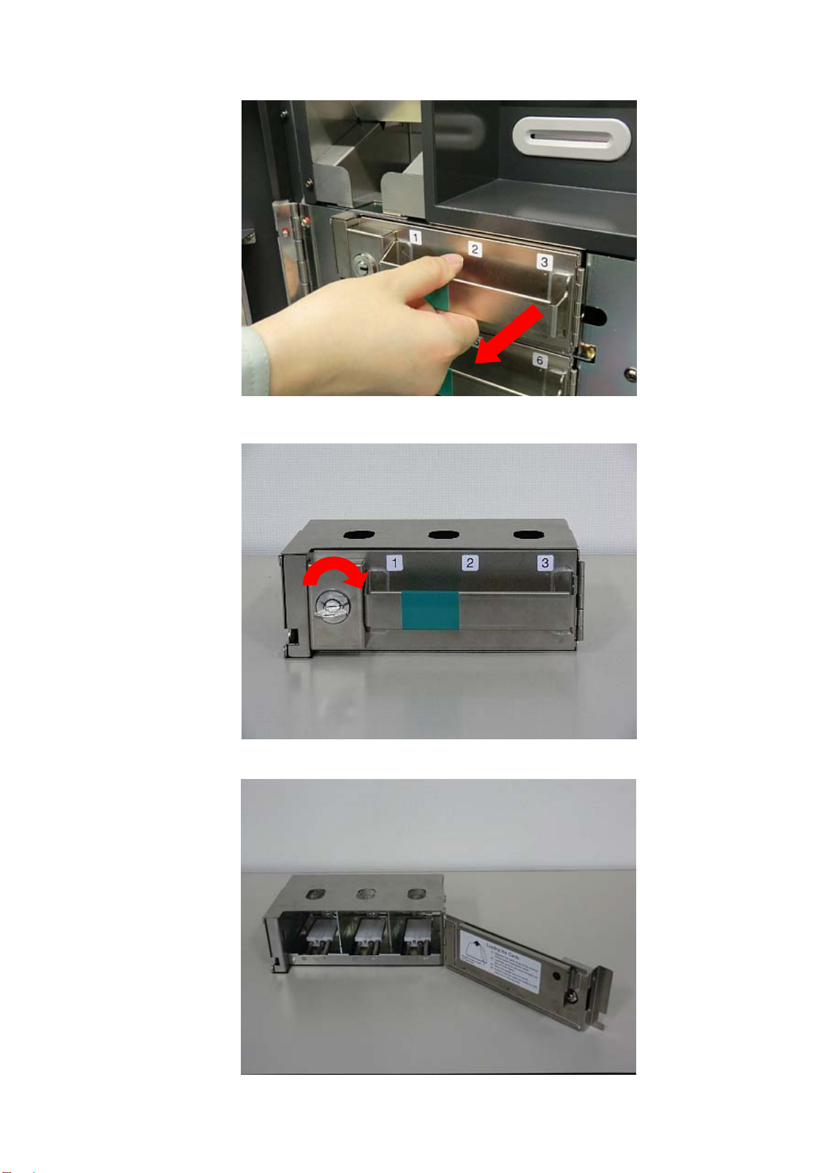
2. Pull out the Hopper Cassette from the main body.
3. Open the Hopper cover by turning the Hopper cassette key clockwise.
7
Turn the hopper cassette key clockwise.
Open the Hopper Cover.
Page 15
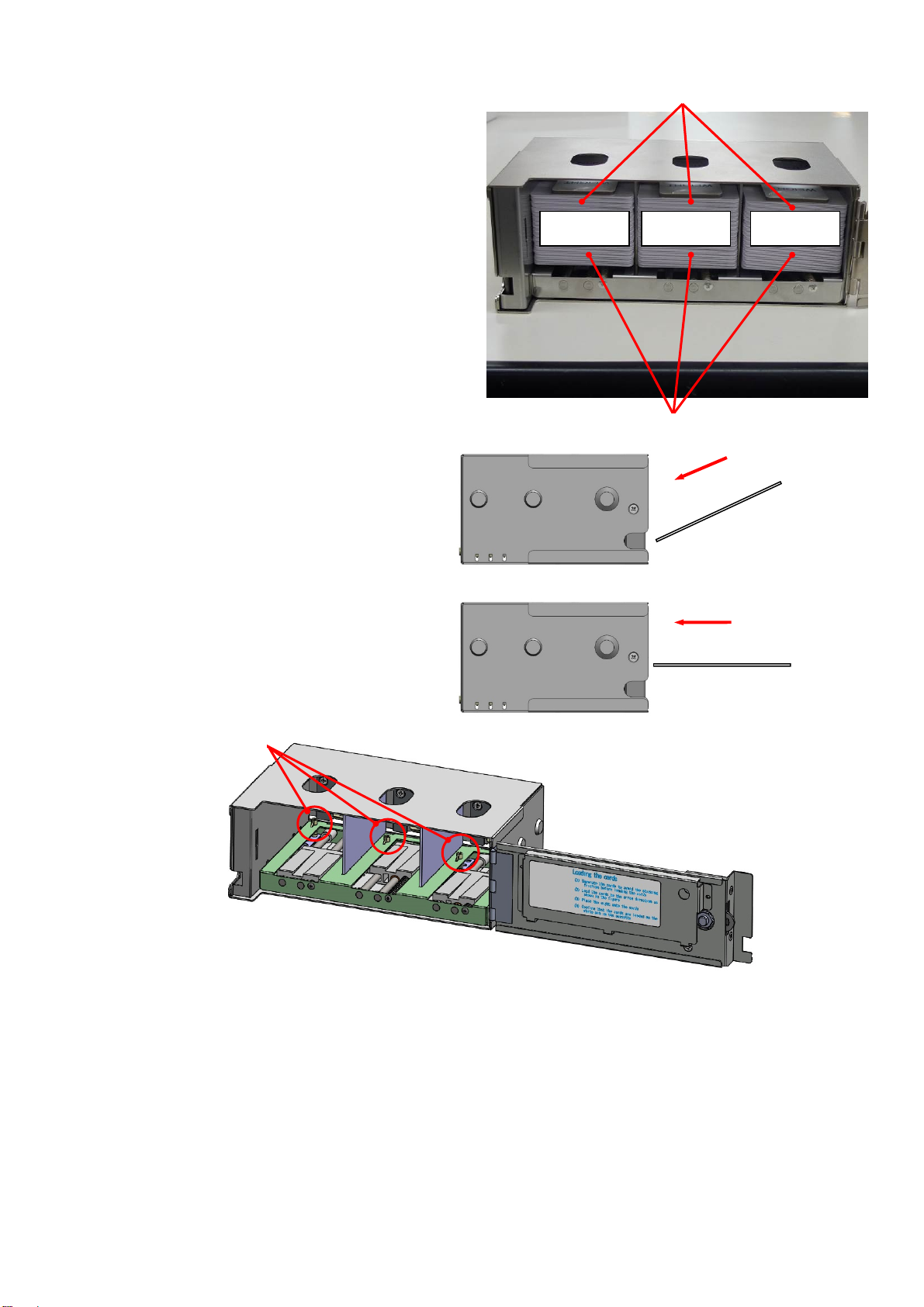
4. Before putting cards into the hopper, they
must be separated to prevent them from
sticking to each other. Then place the cards
into the desired Hoppers. Place a weight on
top of the cards. Close the Hopper cover
and lock by turning the cassette key
counterclockwise.
Each Hopper can hold a maximum of 50
cards.
Please refer to the Illustration inside of the
cassette to find card setting direction.
Placing the cards in an extremely skew
or acute angle may interfere with proper
card seating and cause card jams.
Set the cards on the sensor pin softly
while keeping them horizontally.
Sensor pin
If the edge of a card is out of the Gate, it may cause card jams. In this case, please remove all cards
from the cassette temporally and reseat them according to the step 4 as above.
Max 50
Weight
Max 50 Max 50
Card
NG
OK
8
Page 16
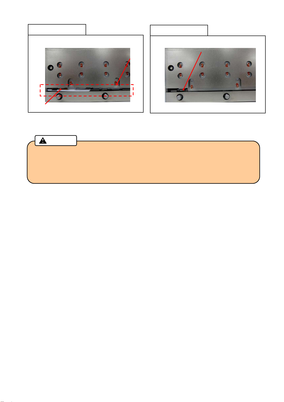
Bad setting example
NG
Card
5. Insert the cassette into the main body until it clicks. Close the Front Cover to lock with the key.
• After separating the cards to prevent them from sticking to each other , check that there is
no foreign object in the input hopper, then place the cards into the cassette.
Card comes out of the Gate
Caution
Gate
Good setting example
OK
Card is placed in cassette properly
• If you see a card edge at the gate, all cards must be taken out from the cassette and
reseated again.
9
Page 17
How to use the machine
Setting and Checking the IP Address
For issuing the cards, this product requires being connected to a host computer by LAN and USB.
To connect to a LAN, you need to set up an IP address.
How to check the existing IP address is described as follows.
1. Turn the power OFF, then open the Right side door by turning the key clockwise.
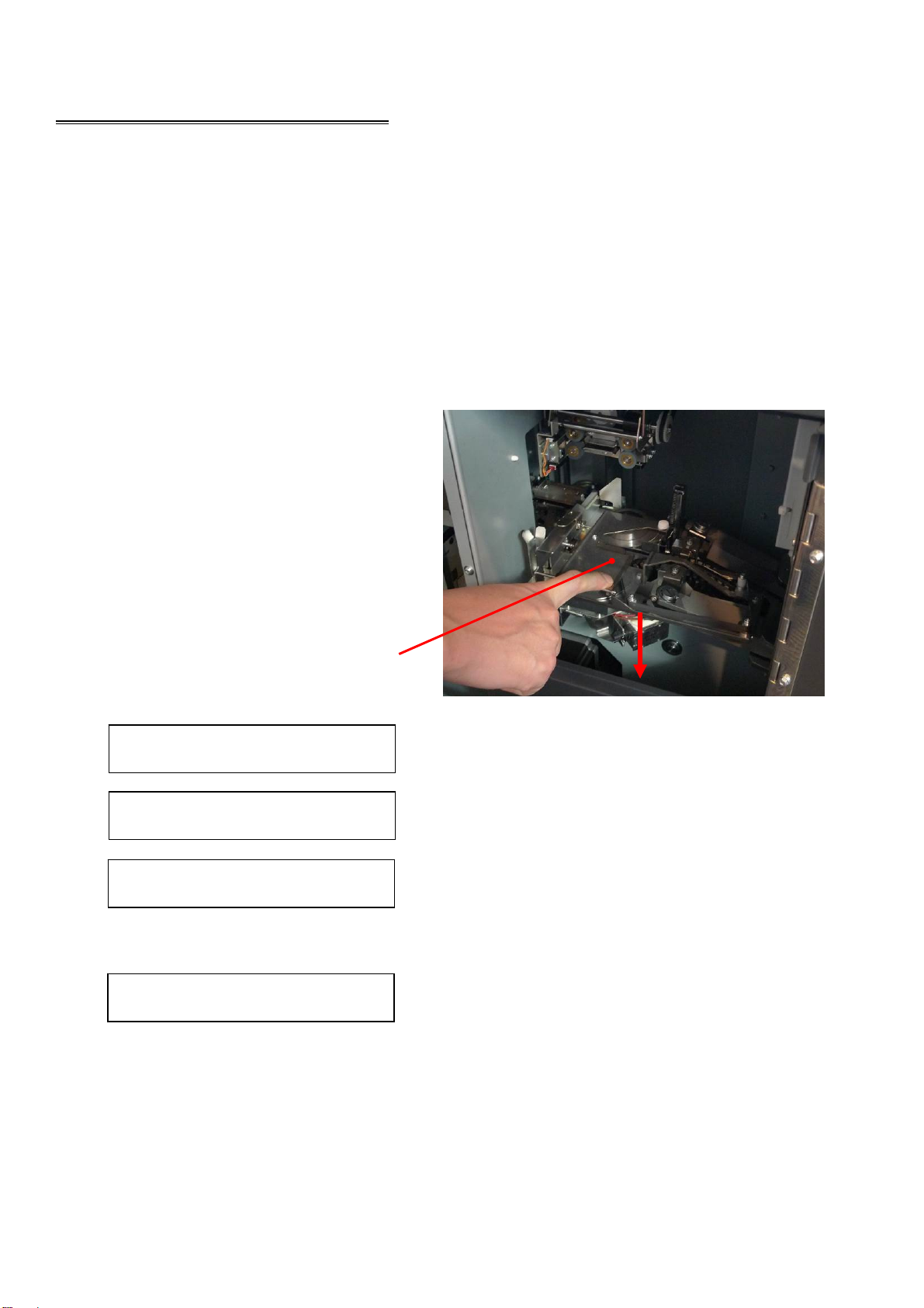
2. While pushing down on the Indent Cassette, turn the power ON.
3. When the buzzer starts beeping, release
the Indent Cassette.
4. The IP address, Subnet mask, and
Gateway will be displayed on the Main
display scrolling every two seconds
repeatedly.
Push the Indent Cassette downward.
Ixxx.xxx.xxx.xxx
Sxxx.xxx.xxx.xxx
Gxxx.xxx.xxx.xxx
While getting an IP address from DHCP server, the Main display shows as follow.
Please wait...
After received IP address, the address is indicated on the Main display.
5. Close the Right side door and lock by the key, then turn the power OFF.
Displayed IP address
Displayed Subnet mask
Displayed Gateway
10
Page 18
Card Issuing
1. Turn the power ON after connecting the power cable and the communication cables.
2. The following message will be indicated on the Main display.
TP Warm-up xx%
(Warming up is not completed when using Tipper.)
Not initialized
(Warming up is completed when using Tipper, or not using Tipper.)
3. Initialization triggered by the host computer.
Initializing...
(During initialization)
4. When initialization is completed, the message will be changed.
Issuing Mode
5. When received Issuing data from the host computer, Issuing operation is started.
Card Issuing
6. Issued card will be stored in the Card Stacker or ejected to the Card Insertion/Exit Slot.
7. Error card will be transferred to the Reject Box.
Reference
• If any error is detected during initialization, an error message is indicated on the Main
display.
Please refer to “Error message” in this manual about the details and its measures.
Caution
• Do not insert a card or cover the Card Insertion/Exit Slot during the operation.
• If you open the Front cover, Side door, or the Top cover during the operation, it will stop
issuing the card. Do not reuse the canceled card because the data was not be
processed correctly. You can restart the machine by turning off and on.
• In the case when the machine got turned off because of power failure or other reasons,
open the Front cover to remove the Hopper cassette. Make sure that the card does not
come out from the rear side of the Hopper cassette, and then turn on the machine
again.
11
Page 19
Exchange of Thermal Transfer Ribbon
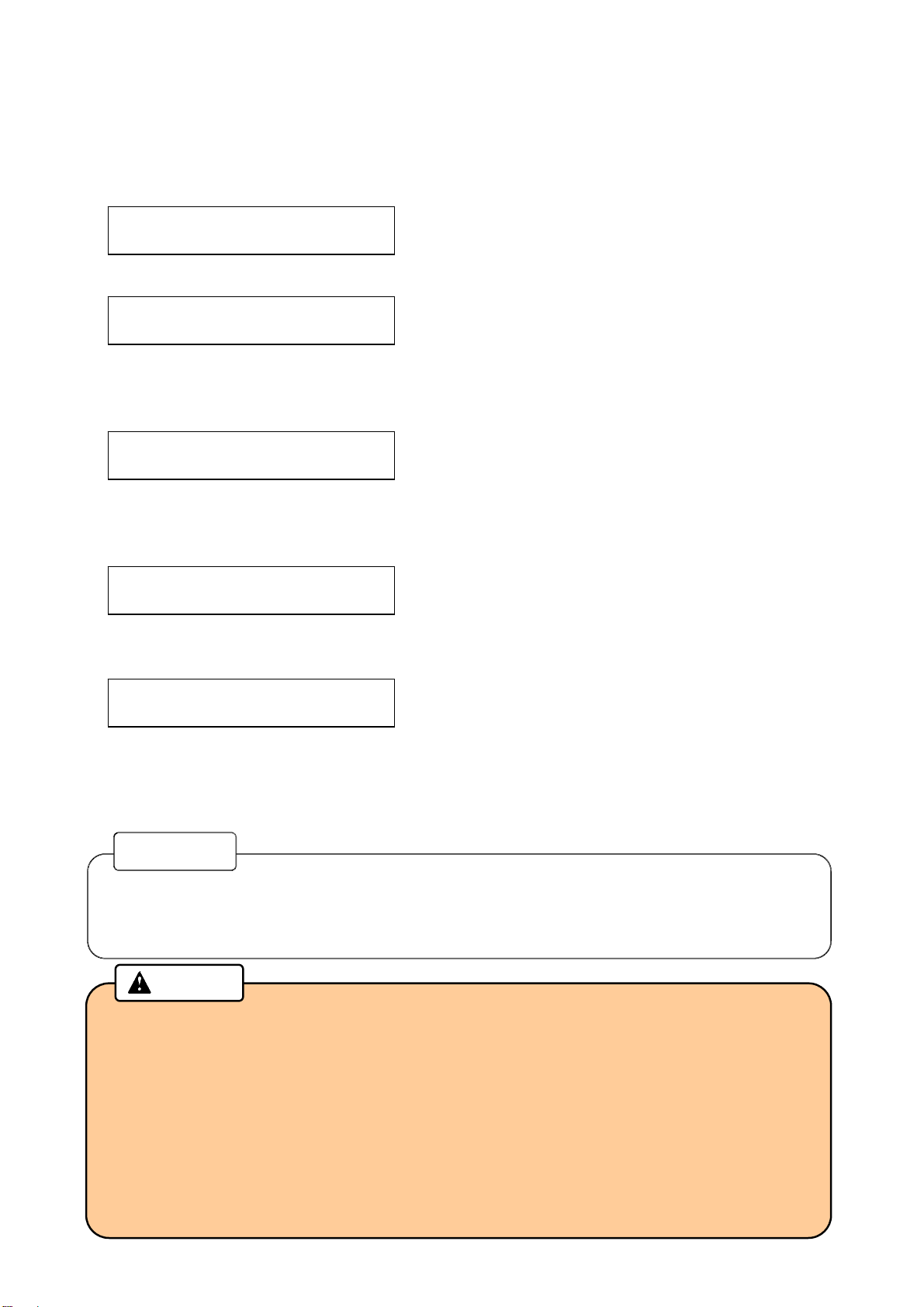
1. Unlock the Top Cover by turning the key clockwise during the power ON, and then open the Top Cover.
The buzzer will beep, and the following error message will be indicated on the Main display.
CV402 Top / Side
2. Push the Print /Encode Unit Cover Open Button to open the cover.
3. Detach the Thermal Transfer Ribbon from the Print /Encode Unit.
Turn this key clockwise.
Print /Encode Unit Cover Open Button
Open Top Cover.
Open Print /Encode Unit cover. Print /Encode Unit
12
Page 20
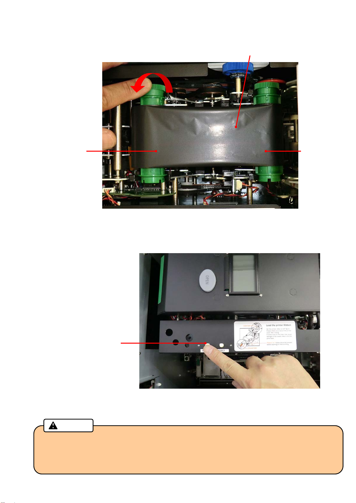
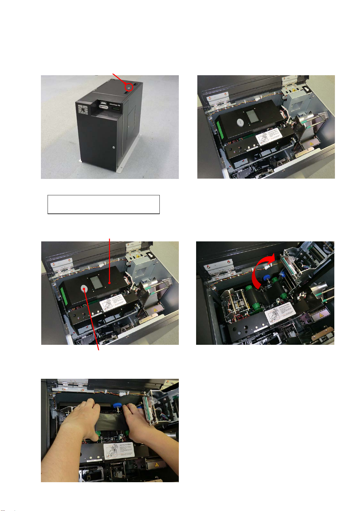
4. Install new Thermal Transfer Ribbon as shown in the picture below, and remove the slack of the ribbon.
Unused side Used side
5. Close the Print/Encode Unit cover until it clicks.
6. Push the RIBBON SET button.
7. Close the Top Cover, and then lock the Top Cover key.
“RIBBON SET” button
Caution
• Be sure to push the "RIBBON SET" button after installing a new ribbon. Otherwise, a print
failure will occur.
• Be sure to remove the slack of the Thermal Transfer Ribbon before closing the cover. The slack
will adversely affect the print quality.
Turn the unused side of the ribbon
counter-clockwise to remove the slack
Thermal Transfer Ribbon
13
Page 21

Exchanging Tipper Foil
1. Turn off the power, and then open the Top Cover by turning the key clockwise.
2. Grab the handle of the Tipper Unit to pull out from the main body.
• There is a very high-temperature part in the Tipper Unit.
Caution
Make sure to grab the handle to avoid a burn when you pull up the Tipper Unit.
Turn this key clockwise.
Open Top Cover.
Handle
14
Page 22

3. Remove the used Tipper Foil and paper core from the Tipper Unit. Pull each knob of the reel
flange/unreel flange while holding the used tipper foil or the paper core to remove.
Unreel Flange Knob
• Be sure to exchange the Tipper Foil after it is sufficiently cooled down.
4. Remove the used Tipper Foil from the reel hardware, then Install the empty paper core to it.
Confirm there is no gap between the paper core and the flange of the reel hardware.
Paper Core
Paper Core
Caution
Used Tipper Foil
Reel Flange Knob
Reel Hardware
Confirm there is no gap
between the paper core
and the Flange of reel
hardware
15
Page 23

pp
5. Insert the Reel hardware to the Tipper Unit while pulling the knob of reel hardware. At this time, fit a
mounting hole of the Reel hardware into a pin on the cassette.
6. Insert the Tipper foil into the Unreel flange while pulling the knob in the direction of the arrow.
7. Pull out the Tipper foil, and fix the edge of the foil to the paper core with an adhesive tape.
New Tipper Foil
Unreel Flange
Turn the Reel flange knob counter-clockwise approximately one turn to wind the foil on the reel.
Knob
Fit this hole to the pin of
er Unit
Ti
Turn the knob one rotation Fix the foil to the Paper Core
16
Page 24

8. Gently slide the tipper Unit into the tipper holder along the guide rail.
Slide in the Tipper
Unit along the
guide rail slowly.
9. Close the Top Cover and lock with the key.
Guide Fin
17
Page 25

Exchanging Indent Film
1. Turn off the power, then turn the Right side door key clockwise to open. If carriage disturbs your access,
push it to the right side.
2. Release lock by pushing the lock lever with holding the Indent Cassette handle, and remove Indent
Cassette upward and forward from the Emboss Unit.
Emboss Unit
Carriage Unit
Lock lever
Handle
Indent Cassette
18
Page 26

3. Remove a thumb-screw and open the Film Guide.
Thumb- screw
4. Remove the Empty Core and used film. Then set the new film to the left and the Empty Core to the right.
5. Peel off the fixing tape on the edge of the new film, and set the film according to the guidance figure for
“Film Setting”. Fix the edge of the film onto the Empty Core with the fixing tape.
At this time, the film should not lie off the core largely.
6. Turn the empty core three times counter-clockwise to remove the slack of the indent film.
Close the Film Guide, and fix the thumb-screw.
Film Guide
Empty Core
New film
Empty Core
Used film
Used film
Guidance figure for
“Film Setting,”
19
Page 27

7. Install the Indent Cassette to the main body. Insert the Guide shaft into the Guide hole of the cassette
while grabbing the lock lever and the handle, and install the cassette until it clicks.
(Refer to the guidance figure for “Indent Cassette Setting” on the Right side door.)
Guide Hole
Guide Shaft
8. After attaching the cassette, check that the film has no slack.
Close the Right side door, and lock with the key.
• Be sure to remove the slack of the Indent Film before installing the Indent Cassette.
• Before installing the halfway used film again, be sure to wind the used part completely.
Caution
The slack may adversely affect the print quality.
Push down the Indent Cassette until it clicks.
Guide Hole
Guide Shaft
20
Page 28

Picking up cards from Output Stacker
1. Turn the power ON and unlock the Front cover by application software.
Then open the Front cover by turning the key clockwise.
When the Front Cover is opened, the buzzer will beep and the following error message will be indicated
on the Main display.
CV401 Front
2. Pick up the cards from the Output Stacker.
3. Close the Front cover, and then lock the Front Cover with the key.
Output Stacker Unit
Turn this key clockwise.
Open Front Cover.
21
Page 29

Picking up cards from Reject Stacker
1. Turn the power ON and unlock the Front cover by application software.
Then open the Front cover by turning the key clockwise.
When the Front Cover is opened, the buzzer will beep and the following error message will be indicated
on the Main display.
CV401 Front
2. Pick up the cards from the Reject Stacker.
3. Close the Front cover, and then lock the Front Cover with the key.
Open Front Cover. Turn this key clockwise.
Reject Stacker Unit
22
Page 30

Eco mode
1. This product has the following two different type Eco (Economy Energy) mode. Each mode can be set
independently.
• Tipper Heater OFF
• Motor OFF
2. Eco mode can be set for the heater and motor as follows:
i. No ( Not change to Eco Mode)
ii. 10 minutes (When the machine has been kept on standby for 10 minutes or more, it shifts to the Eco
mode )
iii. 30 minutes (When the machine has been kept on standby for 30 minutes or more, it shifts to the Eco
mode )
iv. 60 minutes (When the machine has been kept on standby for 60 minutes or more, it shifts to the Eco
mode )
(Factory default setting is “No” for both of Hopper and Motor)
3. During Eco mode, the following message will be indicated on the Main display.
Eco mode Tipper
Eco mode Motor
Eco mode Both
4. Eco mode is canceled by receiving “Clear Eco Mode” command from the host computer.
Tipper is in Eco mode.
Motor is in Eco mode.
Both Tipper and Motor are in Eco mode.
23
Page 31

Error Message
When an error such as operation failure or a malfunction of the machine occurs, the buzzer will beep, and an
error message will be indicated on the Main display or the Print /Encode Unit display.
If the same error occurs repeatedly, please contact your distributor.
Error during standby
An error code is indicated on the Main display when a sensor is defective while standby or the machine is not
ready for starting operation.
You can check the error message on display and the PC screen either.
Error Message Details and Countermeasures
CV301 Lock error Detect electric lock anomaly on Front Cover.
CV302 Unlock err Detect electri c unlo c k anomaly on Front Cover.
CV401 Front Detect Front Cover is open(during standby).
<Close the cover to clear the error>
CV402 Top / Side Detect Top / Right side door is open(during waiting).
<Close the cover to reset the error>
CV512 Sensor err Detect cover sensor anomaly.
<Power OFF and ON>
EJ101 Card full Out Stacker is full.
<Open Front Cover and pick up the cards.>
IH512 Sensor err Detect In Hopper sensor error.
<Power OFF and ON>
RJ101 Card full Reject unit is full by cards.
<Open Front Cover and pick up the cards.>
SY221 Fan1 error Detect abnormality of Cooling Fan.
<Power OFF and ON>
24
Page 32

Consumable error
An error code is indicated on the Main display when a consumable is not set properly or has run out.
Please install the required consumable according to the following messages.
Error Message Details
ID101 No film No Indent film.
ID121 No cst Indent film cassette has not set.
IH101 No card 1 No card in Hopper 1
IH102 No card 2 No card in Hopper 2
IH103 No card 3 No card in Hopper 3
IH104 No card 4 No card in Hopper 4
IH105 No card 5 No card in Hopper 5
IH106 No card 6 No card in Hopper 6
IH107 No card 7 No card in Hopper 7
IH108 No card 8 No card in Hopper 8
IH109 No card 9 No card in Hopper 9
IH110 No card 10
IH111 No card 11
IH112 No card 12
IH113 No card 13
IH114 No card 14
IH115 No card 15
IH121 No cst 1 Hopper cassette 1 is not set.
IH122 No cst 2 Hopper cassette 2 is not set.
IH123 No cst 3 Hopper cassette 3 is not set.
IH124 No cst 4 Hopper cassette 4 is not set.
IH125 No cst 5 Hopper cassette 5 is not set.
TP101 No foil Nof Tipper Foil
TP121 No cst Tipper Unit is not set.
No card in Hopper 10
No card in Hopper 11
No card in Hopper 12
No card in Hopper 13
No card in Hopper 14
No card in Hopper 15
25
Page 33

Error during operation
An error code is indicated on the Main display when the machine does not run properly during operation or
initialization. If the same error occurs repeatedly, please contact your distributor.
Error Message Details and Countermeasures
CA201 Card jam Card Jam (caused by malfunction of motor or sensor in Main Transfer Unit)
< Power OFF, and remove the card >
CA221 Pusher err Pusher motor error detected
<Power OFF and ON >
CA303 Home err Y Home detection error. ( Carrier vertical direction)
<Power OFF and ON >
CA304 Home err Z Home detection error.( Carrier horizontal direction)
<Power OFF and ON>
CA421 Card exist Detect a card remaining on Carrier.
< Power OFF, and remove the card>
CG302 Home err X Home detection error. (horizontal direction)
<Power OFF and ON >
CG303 Home err Y Home detection error . (vertical direction)
<Power OFF and ON >
CG421 Card exist Detect a card remaining on carriage.
< Power OFF, and remove the card>
CM501 Unknown Receive unknown commands.
<Make sure host PC and this product are connected correctly by LAN or USB.>
CM502 Sequence Detect sequence error.
<Make sure host PC and this product are connected correctly by LAN or USB.>
CM503 Parameter Detect parameter error.
<Make sure host PC and this product are connected correctly by LAN or USB.>
CM513 Receive Detect receiving error.
<Make sure host PC and this product are connected correctly by LAN or USB.>
CM514 Send Detect sen ding error.
<Make sure host PC and this product are connected correctly by LAN or USB.>
CV411 Front Detect Front Cover open during card issuance operation.
<Close Front Cover, initialize from host PC.>
CV412 Top / Side Detect Top /Right side door open during card issuance operation.
<Close Top/Right side door, and initialize from host PC.>
DR307 D Pos err Home detection error.( Emboss Drum)
<Power OFF and ON >
DR401 D Rota err Detect an error during drum rotation.
<Power OFF and ON >
EM211 Press err Detect an error during embossing operation.
< Power OFF, remove the card>
26
Page 34

Error Message Details and Countermeasures
EM501 Area err
The data to emboss outside of emboss available area was sent.
<Make sure if emboss data is inside of available area.>
ID401 Cst down
Cassette not moved down position.
<Power OFF and ON >
ID402 Cst up
Cassette not moved up position.
<Power OFF and ON >
ID403 Feed err
Error detected during film rotate operation.
<Power OFF and ON >
ID501 Area err
The data to emboss outside of indent available area was sent.
<Make sure if emboss data is inside of indent available area.>
IN201 Card jam
Card Jam. (caused by malfunction of motor or sensor in Input hopper Unit)
< Power OFF, and remove the card>
IN401 Card eject
IN403 Timeout
The issued card was not pulled out even after a certain period of time.
<
Open Front Cover , and remove the card from Reject Unit.>
Insert waiting time out.
<Insert card within 30 seconds after starting card issuing by application
software.>
IN421 Card exist
Detect a card remaining in Insert slot.
< Remove the card.>
SY101 No Card
Not find a card.
<Make sure if a card does not fall inside the machine.>
SY501 Not init
Card issuance command was sent before initialization.
<Initialize the machine from host PC.>
SY904 FRAM error
Detect FRAM (for data storage) error.
<Power OFF and ON >
TP211 Press err
Detect an error during Tipper foil pressing operation.
<Power OFF and ON >
TP301 HP err
Detect an error during searching home position.
<Power OFF and ON >
TP401 Wup err
Heater temperature does not reach to the established value.
<Power OFF and ON >
TP901 Temp err
Heater temperature could not reach to the established value even after the
specified time has passed.
<Power OFF and ON >
VR201 Card jam
Card Jam.(caused by malfunction of motor or sensor in Vertical Rotation Unit.)
< Power OFF, and remove the card.>
VR221 V Rota err
Detect an error during rotating operation.
<Power OFF and ON >
VR421 Card exist
Detect a card remaining on Vertical Rotation Unit.
< Power OFF, and remove the card>
Caution
・ When serious errors listed above has occurred, be sure to shut down all power before
checking and making any countermeasure action.
・ Be sure to shut down all power and wait more than one hour before checking or
making a measure for Tipper Unit. The Tipper Unit has a high-temperature area, and it
may be the cause of an injury or a burn.
27
Page 35

Error and warning during printing or encoding operation
If an error or warning is indicated by the application software, and no error or warning is indicated on the Main
display, make sure whether it is indicated on the Print /Encode Unit display.
To check the Print /Encode Unit display, please open the Top Cover.
If the same error or warning occurs repeatedly, please contact your distributor.
A. Errors
(1) TPH(Thermal Print Head)
Code Message Details and Countermeasures
10 Top Cover (TPH Module) Print /Encode Unit cover is opened during card printing operation.
<Make sure that the cover is closed properly>
11 TPH Up/Down Failure Up/down movement of the Thermal Print Head is interrupted.
<Repair service is required. Contact your distributor>
13 Abnormal TPH Thermistor
Temperature
(2) Card Feeding
Code Message Details and Countermeasures
12 Card Jammed The card is jammed in Print /Encode Unit.
(3) Ribbon
Code Message Details and Countermeasures
14 Ribbon Encoder Error Run out of Thermal Transfer Ribbon or encoder error occurs.
An abnormal temperature of Thermal Print Head is detected.
<Repair service is required. Contact your distributor>
<Remove the card>
<Make sure that Thermal Transfer Ribbon is not installed
incorrectly, or Thermal Transfer Ribbon has not run out>
(4) Card
Code Message Details and Countermeasures
17 IC Module Up/ Down Error IC Content module position error occurs.
<Repair service is required. Contact your distributor>
50 [Changer] Module Response
Timeout
51 [Changer] Module Transmission
Timeout
52 [Changer] Home Position Failure The Flipper can not be moved back to home position.
53 [Changer] Card Flipper Failure An error occurs when the Flipper turn up.
54 [Changer] Card Input Time out The Print /Encode Unit stops when the card is entering the Flipper.
55 [Changer] Card Input Jam The card fails to enter the Flipper on time.
56 [Changer] Card Output Jam The card is jammed in the Flipper.
57 [Changer] Card Exist The card is not ejected from the Flipper.
Flipper communication error occurs.
<Turn the power OFF, and remove the card from Print /Encode Unit,
turn the power ON>
Flipper communication error occurs.
<Turn the power OFF, and remove the card from Print /Encode Unit,
turn the power ON>
<Turn the power OFF, and remove the card from Print /Encode Unit,
turn the power ON>
<Turn the power OFF, and remove the card from Print /Encode Unit,
turn the power ON>
<Turn the power OFF, and remove the card from Print /Encode Unit,
turn the power ON>
<Turn the power OFF, and remove the card from Print /Encode Unit,
turn the power ON>
<Turn the power OFF, and remove the card from Print /Encode Unit,
turn the power ON>
<Turn the power OFF, and remove the card from Print /Encode Unit,
turn the power ON>
28
Page 36

t
(5) Miscellaneous
Code Message Details and Countermeasures
15 Media Error The media error occurs.
<Make sure whether the card is not set in the wrong direction>
16 EEPROM Error An EEPROM read/ write error occurs.
<Turn the power OFF and back O N>
B. Warning
(1) Card
Code Message Details and Countermeasures
23 [IC] Contact Error
24 [MS] Encoder Error
25 [MS] Read Error
26 [MS] Read STX Error
27 [MS] Read Parity Error
28 [MS] Read ETX Error No ETX is found in read data.
29 [MS] Read LRC Error LRC is inconsistent in dat a that is read from magnetic stripes.
30 IC Module Response Timeout IC module communication failed.
33 Card Eject Error Flipper module communication failed.
34 Card Input Timeou
(2) Ribbon
Code Message Details and Countermeasures
35 Ribbon Life Low Thermal Transfer Ribbon life is reduced to 10% or less.
36 No Ribbon Life Thermal Transfer Ribbon is fully consumed.
38 RF Tag Ribbon Error Thermal Transfer Ribbon is not installed properly.
(3) Miscellaneous
Code Message Details and Countermeasures
20 Command Error Print /Encode Unit receives non-conforming command.
21 Parameter Error The parameter is not valid.
22 Main Communication Part
Timeout
C. Trouble shooting
Symptom Countermeasures
The ribbon is frequently cut, or some part
of data is not printed.
The Print /Encode Unit is unable to find
the programs.
Print /Encode Unit fails to contact IC chip.
<Make sure whether the card is not set in the wrong direction>
Print /Encode Unit fails to encode magnetic stripes.
<Make sure whether the card is not set in the wrong direction>
Print /Encode Unit fails to read magnetic stripes.
<Make sure whether the card is not set in the wrong direction>
No STX is found in read data.
<Make sure whether the card is not set in the wrong direction>
A p arity error occurs when Print /Encode Unit read the data from
magnetic stripes.
<Make sure whether the card is not set in the wrong direction>
<Make sure whether the card is not set in the wrong direction>
<Make sure whether the card is not set in the wrong direction>
<Make sure whether the card is not set in the wrong direction>
<Turn the power OFF, and remove the card from Print /Encode Unit,
turn the power ON>
The card input is interrupted.
<Make sure whether any cards are not jammed in the path from the
Input Hopper to Print /Encode Unit>
<Prepare to replace Thermal Transfer Ribbon>
<Replace the Thermal Transfer Ribbon with a new one>
<Make sure whether Thermal Transfer Ribbon is not installed in the
wrong direction>
<Contact your distributor>
<Contact your distributor>
The command is not sent on time.
<Contact your distributor>
Check the X-coordinate in the printer driver.
<The recommended starting value for the X- coordinate is 14 ± 2>
Make sure host PC and this product are connected correctly by
LAN or USB.
<Reboot the PC>
29
Page 37

Error Reset
Removing the card remaining in Input Hopper
1. Turn the power ON and unlock the Front cover by the application software.
Then open the Front cover by turning the key clockwise.
2. Remove the Hopper Cassette that has the remaining card.
3. Remove the card from the rear side of the Hopper Cassette.
Turn this key clockwise.
Pull to remove the card
Hopper Cassettes
Hopper Cassette
Remaining Card
30
Page 38

* If the card cannot be pulled out from the rear side of the Hopper Cassette, open the Hopper Cover by
turning its key clockwise.
Remove all weight and cards, and pull out the remaining card from the Hopper.
4. Close the Hopper Cover and install the Hopper Cassette to the machine.
Close the Front Cover and lock the Key by turning it counterclockwise.
Remaining card
Hopper Cover
Remove the
remaining card
from the front.
31
Page 39

Removing the card remaining in Main Transfer Unit
1. Turn the power OFF, and open the Right side door by turning the key clockwise.
2. Check if any cards are remaining in the Carrier of the Main Transfer Unit.
Turn this key clockwise
Carrier of the Main Transfer Unit
Open Right side door
32
Page 40

If the remaining card is not on the Carrier, turn the Knob (X) to carry the card toward the Carrier.
When you cannot access the Carrier, grip Knob (Z) and pull the Carrier forward.
Turn the Knob (X) clockwise to
carry the card to the right side.
Turn the Knob (X) counter-clockwise
to carry the card to the left side.
33
Page 41

3. Grip the Knob (Y) and move the Carrier to the height between the Vertical Rotation Unit and the Indent
Unit.
While holding the Knob (Y), turn the Knob (X) clockwise to bring out the card from the Carrier. Pull out the
card by hand.
4. Close the Right side door and lock with the key.
Knob (Y)
Knob (X)
Vertical Rotation Unit Indent Unit
Pull out the card
from the Carrier
by hand.
Hold the Carrier
while removing
the card.
34
Page 42

Removing the card remaining in Print /Encode Unit
1. Turn the power OFF, open Right side door by turning the key clockwise.
Open Top Cover by turning the key clockwise.
2. Push down the button to open the Print /Encode Unit cover.
Turn this key clockwise
Turn this key clockwise.
Print /Encode Unit cover
Print /Encode Unit Cover Open Button
Open Right side door
Open Top Cover.
Open Print /Encode Unit cover.
35
Page 43

3. Detach the Thermal Transfer Ribbon from the Print /Encode Unit.
4. Transfer the card toward the Main Transfer Unit by turning Knob counterclockwise.
Transfer the remaining card
to Main Transfer Unit
5. Pull out the card from the left side of the Print /Encode Unit.
Remaining Card Pull out the card from the Print/Encode Unit.
Turning knob counterclockwise
Remaining card
36
Page 44

6. Reattach the Thermal Transfer Ribbon as shown in the picture below.
Remove the slack of the ribbon by turning the unused side of the ribbon counter-clockwise.
Turn the unused side of the
ribbon counter-clockwise.
Unused side
7. Close the Print/Encode Unit cover until it clicks.
8. Close the Top Cover, and then lock the Top Cover with the key.
9. Close the Right side door, and then lock the Right side door with the key.
10. Turn the power ON, and initialize the machine.
11. Open the Top Cover by turning the key clockwise while power ON.
* Ignore buzzer beeping and the following error message in the Main display to proceed next step.
CV402 Top / Side
Thermal Transfer Ribbon
Used side
37
Page 45

12. Push the RIBBON SET button.
“RIBBON SET” button
13. Close the Top Cover, and then lock the Top Cover with the key.
Caution
• Do not forget to push "RIBBON SET" button after installing a new ribbon. Otherwise, a print
failure will occur.
• Be sure to remove the slack of the Thermal Transfer Ribbon before closing the cover. The
slack will adversely affect the print quality.
38
Page 46

Removing the card remaining in Vertical Rotation Unit
1. Turn the power OFF, and open the Right side door by turning the key clockwise.
2. Remove the remaining card from the right side of the Vertical Rotation Unit.
3. Close Right side door, and then lock the Right side door with the key.
Turn this key clockwise
Open Right side door
Vertical Rotation Unit
Remaining Card
39
Page 47

Removing the card remaining in Carriage Unit
1. Turn the power OFF, and then open the Top Cover by turning the key clockwise.
2. Check where the Carriage Unit stops.
In the case when the Carriage Unit stops around the Tipper Unit, wait more than one hour until the T ip per
Unit is cooled down.
After the Tipper Unit has completely cooled down, proceed to the step 3.
Turn this key clockwise.
Tipper Unit
If the Carriage Unit stops at the
upper right position, wait until
the Tipper unit is cooled down.
Open Top Cover.
40
Page 48

3. Open needle lever by pushing shaft with holding the remaining card.
Remove the card from the Carriage Unit.
* Be careful not to drop the card into the machine (Unless holding the card, it will drop into the machine
when needle lever is opened).
Remaining
Card
Open Needle Lever by pushing the shaft
4. Close Top Cover and lock by the key.
Caution
• Tipper Unit has a very high-temperature part.
If you make the above process, turn off the power and wait at least 1 hour until the Unit has
been completely cooled down to prevent your arms or hands from getting burned.
Needle Lever
Shaft
Push the shaft backward
with holding the card
Carriage Unit
41
Page 49

Removing the card remaining in Emboss Unit
1. Turn the power OFF, and open the Right side door by turning the key clockwise.
Open the Top Cover by turning the key clockwise.
Emboss Unit
Turn this key clockwise
Emboss Type
Remaining Card
(Card is remaining between emboss type in Emboss Unit.)
Open Right side door
Remaining
Card
Emboss Unit
Open Top Cover Turn this key clockwise
* In the case when the card is
remaining in Emboss Unit
and held by Needle lever of
Carriage Unit, remove the
card from the Carriage by
opening the needle lever as
shown on page 40 in this
manual.
42
Page 50

2. Ensure an Emboss type is aligned to the emboss pin.
If they are not aligned each other, it may damage the
Emboss type.
・When the Emboss Type is not aligned to the Emboss Pin, rotate the Emboss Drum to set the Emboss Type
to the right position.
Emboss Type
Emboss Pin
Emboss Unit
Emboss Drum
Emboss Type and Emboss Pin are aligned.
43
Page 51

3. Turn the Crankshaft clockwise by a flat-head screwdriver to open the press bars completely while holding
the card. Then remove the card.
If the Crankshaft got turned too much, Press Bars would return to the Press Position. In this case, turn the
screwdriver counter-clockwise.
4. Make sure that the Emboss Type is aligned to the Emboss Pin again.
Keep the Press Bars opening until the Right side door is closed.
5. Close the Right side door, and then lock the Right side door with the key.
Caution
• There is a high-temperature area in the Tipper Unit.
To perform the above process, turn off the power and wait at least 1 hour until the Unit
has been completely cooled down to prevent your arms or hands from getting burned.
• When turning the Crankshaft, make sure the Emboss type is aligned to the Emboss pin.
(In the case when the emboss type is in the wrong position, the type may be damaged.)
• After completing the above process, make sure the following.
“Emboss type is aligned to Emboss pin.”
“Press Bars has left opened.”
Press Bar
Crankshaft
Press Bar
44
Page 52

Removing the card remaining in Card Insertion/Exit Slot
1. If a card was not ejected completely from the Card Insertion/Exit Slot, pull out the card by hand.
Card
Insertion/Exit
Slot
2. Remove the card according to the pro cedure “Remov e the card in Main Transfer Unit” on page 30 when
you cannot pull the card out by hand.
Pull
Remaining
Card
45
Page 53

Cleaning
Cleaning Thermal Print Head
If you find stain or contamination on the issued cards, clean the Thermal Print Head with a Cleaning pen
(sold separately).
1. Unlock the Top Cover by turning the key clockwise during the power on, and then open the Top Cover.
The buzzer will beep, and the following error message will be indicated on the Main display.
CV402 Top / Side
2. Push the Print /Encode Unit Cover Open Button to open the cover.
Turn this key clockwise.
Print /Encode Unit
Print /Encode Unit Cover Open Button
Open Top Cover.
Open Print /Encode Unit cover.
Thermal Print Head
46
Page 54

3. Clean the Thermal Print Head by using a Cleaning pen.
Reference
• Recap the pen after cleaning for reuse.
Caution
• Do not touch the Thermal Print Head with your fingers.
4. Wind the unused side of the Thermal Transfer Ribbon counter-clockwise to remove the slack.
Unused side Used side
5. Close the Print /Encode Unit cover until it clicks.
Caution
• Before closing the Print /Encode Unit cover, make sure the alcohol on the Thermal Print
Head has evaporated.
Wind the ribbon
Thermal Transfer Ribbon
47
Page 55

6. Push the RIBBON SET button.
“RIBBON SET” button
8. Close the top cover, and then lock the top cover with the key.
• Do not forget to push "RIBBON SET" button after installing a new ribbon. Otherwise, a print
• Be sure to remove the slack of the Thermal Transfer Ribbon before closing the cover. The slack
Caution
failure will occur.
will adversely affect the print quality.
48
Page 56

Washing Cleaning Roller
Cleaning roller will remove stain or contamination on cards and will get dirty gradually. If you find stain or
contamination on the issued cards, wash the Cleaning roller. We recommend washing the Cleaning roller
when replacing the Thermal Transfer Ribbon.
1. Unlock the Top Cover by turning the key clockwise during the power on, and then open the Top Cover.
The buzzer will beep, and the following error message will be indicated on the Main display.
CV402 Top / Side
2. Push the Print/Encode Unit Cover Open Button to open the cover.
Turn this key clockwise.
Print /Encode Unit Cover Open Button
Open Top Cover.
Open Print /Encode Unit cover. Print /Encode Unit
49
Page 57

3. Detach the Thermal Transfer Ribbon from the Print /Encode Unit.
4. Remove the Cleaning roller from the Print /Encode Unit.
5. Wash the Cleaning roller with running water.
6. Install the Cleaning roller to Print /Encode Unit after drying.
Cleaning roller
Detach this side first to take out the Cleaning Roller
50
Page 58

r
7. Reattach the Thermal Transfer Ribbon as shown in the picture below and remove the slack of the
ribbon.
Unused side Used side
8. Close the Print /Encode Unit cover until it clicks.
9. Push RIBBON SET button.
“RIBBON SET” button
10. Close the top cover, and then lock the top cover with the key.
• Do not forget to push "RIBBON SET" button after installing a new ribbon. Otherwise, a print
• Be sure to remove the slack of the Thermal Transfer Ribbon before closing the cover. The slack
Caution
failure will occur.
will adversely affect the print quality.
Turn unused side of the ribbon
counte
-clockwise to remove the slack
Thermal Transfer Ribbon
51
Page 59

Cleaning Card transfer rollers
1. Turn the power OFF, and open the Right side door by turning the key clockwise.
Vertical Rotation Unit
Turn this key clockwise
Main Transfer Unit
Open Right side door
52
Page 60

2. Clean the Card transfer rollers on the Main Transfer Unit.
Clean the two Drive Rollers (lower side) and the two Passive Rollers (upper side) while turning the knob.
Use a waste cloth or a cotton swab absorbed with Ethanol.
3. Clean the Card transfer rollers on the Vertical Rotation Unit.
Clean the Drive Roller and the three Passive Rollers while turning the white gear.
Use a waste cloth or a cotton swab absorbed with Ethanol.
Drive Roller
Passive Rollers
Drive Rollers
Passive Roller
Gear
Knob
53
Page 61

Specifications
The following specifications may be changed without notice.
General Specifications
Name Card Printer & Embosser
Model Advantage M8
Usable card
(Allocable PVC Card)
Connection Interface
Display
Input Hopper
Out Stacker
Rejected Cards
Card Counter
Magnetic stripe / IC : ISO 7810 ID-1
* Height of warped card must be less than 1mm including thickness of the card.
USB2.0(Full Speed) (cable 3m in length or less)
LAN 10BASE-T/100BASE-TX
Liquid Crystal Display(16 digits ×1 line)Character back light
Number of cassettes 2 (*Option total 5 cassettes are available.)
6 (3 hoppers per cassette)
(*When setting optional cassettes:
Number of hoppers
Input Hopper Capacity
Card Presence Detection Out of Card detection
Manual insert mode Available
Output Stacker Capacity Approximately 20 cards
Card presence detection Card-full detection
Reject stacker capacity Approximately 25 cards
Card presence detection Card-full detection
Resettable Software counter
Non resettable Mechanical counter
3 cassettes are set : 9
4 cassettes are set : 12
5 cassettes are set : 15)
300 cards (50 cards per hopper)
(*When setting optional cassettes:
3 cassettes are set : 450 cards
4 cassettes are set : 600 cards
5 cassettes are set : 750 cards.)
Dimensions 456mm (W) x 658mm (H) x 771mm (D)
Weight
Power voltage AC220 - 230V 3.0A 50Hz/60Hz AC100 - 120V 4.5A 50Hz/60Hz
User environment
Security
Applicable Standard
* About option, please contact your distributor.
54
81kg(including 2 Hopper cassettes)* excluding card weight
Operating environment
Temperature 10 to 32 degrees Celsius
Humidity 20 to 65% R.H(non-condensing)
Guaranteed accuracy environment
Temperature 18 to 28
Humidity 40 to 65% R.H.(non-condensing)
Key lock for Front Cover, Right side door and Top Cover (Same for all key rocks)
Software rock (Front)
Key lock for Hopper cassette (Same for all key rocks)
Safety : CE marking (Low Voltage), EMC : CE marking(EMC), FCC Class A
degrees Celsius
Page 62

Embosser Specifications
Emboss ISO 7811-1
Emboss printing
type capacity
54 characters (standard) 80 characters at maximum (Including indent
printing types.)
Alphabet (10 CPI) 26 characters “A to Z”
Emboss printing
character type
Possible emboss area
Emboss cross-feed pitch
Indent printing
character type
Indent Film Detection Film-end detection
Possible Indent area
Tipper Foil color Silver, (Gold)
Tipping Foil Detection Foil-end detection
Number (10 CPI) 10 characters “0 to 9”
Number (7 CPI) 10 characters “0 to 9” (OCR-7B)
Symbol (10 CPI) 8 characters “- / . ' , ( ) &”
Lower limit:(5.1 ㎜ from lower end of the card to character center line)
Upper limit:(21.4 ㎜ from lower end of the card to character center line)
Left limit:(7.7 ㎜ from left end of the card to character center line)
Right limit:(75.5 ㎜ from left end of the card to character center line)
1/7inch(Up to 19 digits can be embossed)
1/10inch(Up to 27 digits can be embossed)
10 characters “0 to 9” (OCR-B (14CPI)) (*Option Reverse italic)
Lower limit:(15.2 ㎜ from lower end of the card to character center line)
Upper limit:(37.8 ㎜ from lower end of the card to character center line)
Left limit:(3.7 ㎜ from left end of the card to character center line)
Right limit:(81.3 ㎜ from left end of the card to character center line)
Tipper heater
warm up time
Within 6 minutes
Encoder Specifications
Magnetic Stripe Encode ISO 7811-2/-6(T rack 1, 2, 3: Hi-Co &Lo-Co )
IC Encode ISO 7816 , EMV Level 1 and PBOC 3.0
Contactless IC Encode Mifare® standard, ISO-14443A&B
Printer Specifications
Print Mode
Print Side Dual side
Print resolution 300dpi
Color(Dye-sublimation), Mono(Thermal transfer)
Restriction of Usable card
Cannot print on not flat area such as signature panel or hologram sheet.
55
Page 63

User environment
100%
80%
60%
40%
20%
Temperature ×Humidity = 900
0%
0°C 10°C 20°C 30°C 40°C
Guaranteed
accuracy
environmen
Operating environment
Guaranteed
accuracy
environment
Operating
environment
Temperature
Humidity 40 to 65% R.H.
Temperature 10 to 32 degrees
Humidity 20 to 65% R.H.
18 to 28 degrees
Celsius
Celsius
56
Page 64

Specifications are subject to change without notice.
Advantage M8 Operation Manual
Sales origin : NBS Technologies Inc.
Manufacturer : NBS Card Corporation
Advantage M8-UM-153
June 7, 2018 4rd edition
57
 Loading...