

Granville-Phillips - AKA Brooks 275 User Manual

Series 275
Granville-Phillips® Series 275
®
Mini-Convectron
Vacuum Gauge Module
with Nonlinear Analog Outputs and Process
Control Relays
Instruction Manual
Instruction manual part number 275512
Revision A - February 2013


Series 275
Granville-Phillips® Series 275
®
Mini-Convectron
Vacuum Gauge Module
with Nonlinear Analog Outputs and Process
Control Relays
This Instruction Manual is for use with all Granville-Phillips Series
275 Mini-Convectron Vacuum Gauge Modules With Nonlinear
Analog Outputs and Process Control Relays. A list of applicable
catalog numbers is provided on the following page.
Customer Service/Support
For customer service within USA, 8 AM to 5 PM
Mountain Time Zone, weekdays excluding holidays:
Granville-Phillips
6450 Dry Creek Parkway
Longmont, CO 80503 USA
Phone: +1-800-776-6543
Phone: +1-303-652-4400
FAX: +1-303-652-2844
Email: co-csr@brooks.com
Brooks Automation, Inc.
15 Elizabeth Drive
Chelmsford, MA 01824 USA
Phone: +1-978-262-2400
For customer service, 24 hours per day, 7 days per week,
every day of the year including holidays within the USA:
Phone: +1-800-367-4887
www.brooks.com
Instruction Manual
© 2013 Brooks Automation. All rights reserved.
Granville-Phillips
All other trademarks and registered trademarks are the properties of their respective owners.
®
and Convectron
®
are registered trademarks of Brooks Automation, Inc.

Catalog numbers for Series 275 Mini-Convectron Modules (CE Marked)
With electrical connector. Operating power: 11.5 Vdc to 26.5 Vdc
Mini-Convectron Module with one setpoint relay
1/8 NPT / 1/2 inch tubulation 275800-EU
1/4 inch VCR-type female fitting 275801-EU
1/2 inch VCR-type female fitting 275863-EU
3/8 inch VCO-type male fitting 275802-EU
1.33 inch (NW16CF) ConFlat-type flange 275803-EU
2.75 inch (NW35CF) ConFlat-type flange 275804-EU
NW16KF flange 275806-EU
NW25KF flange 275807-EU
NW40KF flange 275808-EU
Mini-Convectron Module with two setpoint relays
1/8 NPT / 1/2 inch tubulation 275870-EU
1/4 inch VCR-type female fitting 275871-EU
1/2 inch VCR-type female fitting 275867-EU
3/8 inch VCO-type male fitting 275872-EU
1.33 inch (NW16CF) ConFlat-type flange 275873-EU
2.75 inch (NW35CF) ConFlat-type flange 275874-EU
NW16KF flange 275876-EU
NW25KF flange 275877-EU
NW40KF flange 275878-EU
Mini-Convectron Module with two setpoint relays and 3-digit digital display
Display in Torr
1/8 NPT / 1/2 inch tubulation 275904-EU
1/4 inch VCR-type female fitting 275905-EU
1/2 inch VCR-type female fitting 275906-EU
3/8 inch VCO-type male fitting 275907-EU
1.33 inch (NW16CF) ConFlat-type flange 275908-EU
2.75 inch (NW35CF) ConFlat-type flange 275909-EU
NW16KF flange 275911-EU
NW25KF flange 275912-EU
NW40KF flange 275913-EU
Display in Pascal
1/8 NPT / 1/2 inch tubulation 275904-EU-P
1/4 inch VCR-type female fitting 275905-EU-P
1/2 inch VCR-type female fitting 275906-EU-P
3/8 inch VCO-type male fitting 275907-EU-P
1.33 inch (NW16CF) ConFlat-type flange 275908-EU-P
2.75 inch (NW35CF) ConFlat-type flange 275909-EU-P
NW16KF flange 275911-EU-P
NW25KF flange 275912-EU-P
NW40KF flange 275913-EU-P

Table of Contents
Chapter 1 Before You Begin . . . . . . . . . . . . . . . . . . . . . . . . . . . . . . . . . . . . 7
1.1 About These Instructions . . . . . . . . . . . . . . . . . . . . . . . . . . . 7
1.2 Customer Service . . . . . . . . . . . . . . . . . . . . . . . . . . . . . . . . 7
1.3 Caution and Warning Statements . . . . . . . . . . . . . . . . . . . . 8
1.4 System Grounding . . . . . . . . . . . . . . . . . . . . . . . . . . . . . . . 8
1.5 Implosion / Explosion . . . . . . . . . . . . . . . . . . . . . . . . . . . . . 9
1.6 Operation . . . . . . . . . . . . . . . . . . . . . . . . . . . . . . . . . . . . . . 9
1.7 Reading and Following Instructions . . . . . . . . . . . . . . . . . . 10
Chapter 2 Installation . . . . . . . . . . . . . . . . . . . . . . . . . . . . . . . . . . . . . . . . . . 11
2.1 Module Components . . . . . . . . . . . . . . . . . . . . . . . . . . . . . 11
2.2 Installing Pressure Relief Devices . . . . . . . . . . . . . . . . . . . . 12
2.3 Installation Procedure . . . . . . . . . . . . . . . . . . . . . . . . . . . . . 13
Step 1 Locate and orient the module . . . . . . . . . . . . . . . . . . . . . . . 13
Locate the Module . . . . . . . . . . . . . . . . . . . . . . . . . . . . . . . 13
Orient the Module . . . . . . . . . . . . . . . . . . . . . . . . . . . . . . . 15
Step 2 Attach the module to the vacuum chamber . . . . . . . . . . . . . 16
1/8 NPT pipe thread . . . . . . . . . . . . . . . . . . . . . . . . . . . . . . 16
VCR type fitting . . . . . . . . . . . . . . . . . . . . . . . . . . . . . . . . . . 16
KF flange . . . . . . . . . . . . . . . . . . . . . . . . . . . . . . . . . . . . . . . 16
ConFlat flange . . . . . . . . . . . . . . . . . . . . . . . . . . . . . . . . . . . 16
Step 3 Assemble and connect the wiring . . . . . . . . . . . . . . . . . . . . 17
Connecting Cable . . . . . . . . . . . . . . . . . . . . . . . . . . . . . . . . 17
Wiring Terminals . . . . . . . . . . . . . . . . . . . . . . . . . . . . . . . . 17
Grounding . . . . . . . . . . . . . . . . . . . . . . . . . . . . . . . . . . . . . 18
Step 4 Configure the setpoint relays for the application . . . . . . . . . 19
Step 5 Calibrate the Convectron gauge . . . . . . . . . . . . . . . . . . . . . 19
Atmospheric Pressure Calibration . . . . . . . . . . . . . . . . . . . . 19
Vacuum Chamber Pressure Calibration . . . . . . . . . . . . . . . . 19
Chapter 3 Operation . . . . . . . . . . . . . . . . . . . . . . . . . . . . . . . . . . . . . . . . . . . . 21
3.1 Preparing to Operate the Module . . . . . . . . . . . . . . . . . . . . 21
3.2 Nonlinear Analog Output . . . . . . . . . . . . . . . . . . . . . . . . . . 26
Commonly used Gases Other than N2 or Air . . . . . . . . . . . . 26
Other Gases . . . . . . . . . . . . . . . . . . . . . . . . . . . . . . . . . . . . 26
3.3 Setpoint Relays . . . . . . . . . . . . . . . . . . . . . . . . . . . . . . . . . . 37
Preparing to Adjust Setpoint Relays . . . . . . . . . . . . . . . . . . . 38
Adjusting Setpoint Relays . . . . . . . . . . . . . . . . . . . . . . . . . . 39
3.4 Reading Relay Status . . . . . . . . . . . . . . . . . . . . . . . . . . . . . . 42
3.5 Calibrating Convectron Gauge at Atmospheric Pressure . . . 42
3.6 Calibrating Convectron Gauge at Vacuum Chamber Pressure 44
3.7 Modules Operating at Low Pressure . . . . . . . . . . . . . . . . . . 44
3.8 Factory Settings . . . . . . . . . . . . . . . . . . . . . . . . . . . . . . . . . . 45
Mini-Convectron Module Instruction Manual - 275512 - Rev. A 5

Table of Contents
Chapter 4 Maintenance . . . . . . . . . . . . . . . . . . . . . . . . . . . . . . . . . . . . . . . . . 47
4.1 Customer Service . . . . . . . . . . . . . . . . . . . . . . . . . . . . . . . . 47
Damage Requiring Service . . . . . . . . . . . . . . . . . . . . . . . . . 47
4.2 Troubleshooting . . . . . . . . . . . . . . . . . . . . . . . . . . . . . . . . . 48
Precautions . . . . . . . . . . . . . . . . . . . . . . . . . . . . . . . . . . . . . 48
Symptoms, Causes, and Solutions . . . . . . . . . . . . . . . . . . . . 49
4.3 Convectron Gauge Test . . . . . . . . . . . . . . . . . . . . . . . . . . . . 50
4.4 Convectron Gauge Removal and Replacement . . . . . . . . . . 51
Removing the Convectron Gauge . . . . . . . . . . . . . . . . . . . . 51
Replacing the Convectron Gauge . . . . . . . . . . . . . . . . . . . . 51
4.5 Returning a Product for Repair . . . . . . . . . . . . . . . . . . . . . . 52
Appendix A Specifications . . . . . . . . . . . . . . . . . . . . . . . . . . . . . . . . . . . . . . . . 53
Appendix B Theory of Operation . . . . . . . . . . . . . . . . . . . . . . . . . . . . . . . . . . 57
Index . . . . . . . . . . . . . . . . . . . . . . . . . . . . . . . . . . . . . . . . . . . . . . . . . . . . . . . . . . . . . . . . . . . . . . . . . . . . 59
6 Mini-Convectron Module Instruction Manual - 275512 - Rev. A
Chapter 1 Before You Begin
1.1 About These Instructions These instructions explain how to install, operate, and maintain the
Granville-Phillips® Mini-Convectron® vacuum gauge module.
• This chapter explains caution and warning statements, which must be
adhered to at all times; explains your responsibility for reading and
following all instructions; defines the terms “module” and “Convectron
gauge”; and tells you how to contact customer service.
• Chapter 2 explains how to install the module.
• Chapter 3 explains how to operate the module, which has two
programmable setpoint relays.
• Chapter 4 explains troubleshooting, Convectron gauge testing, removal
and replacement, and module return procedures.
• Appendix A provides specifications for the module.
• Appendix B explains terminology and explains how the Convectron
convection-enhanced Pirani heat-loss gauge measures pressure.
Table 1-1 Terms Describing the Mini-Convectron Module and Components
Term Description
Module The Mini-Convectron vacuum gauge module, which contains a Convectron
convection-enhanced Pirani heat-loss pressure gauge.
Convectron gauge The Convectron convection-enhanced Pirani heat-loss gauge, which measures
pressure within the vacuum chamber
Before You Begin Installation Operation Maintenance
1.2 Customer Service For customer service:
• Phone 1-303-652-4400 or 1-800-776-6543 within USA
• Phone 1-800-367-4887 24 hours per day, 7 days per week within the
USA
• Email co-csr@brooks.com
• For Global Customer Support, go to www.brooks.com and click on
Services to locate the Brooks Automation office nearest you.
Mini-Convectron Module Instruction Manual - 275512 - Rev. A 7
Chapter 1
CAUTION
WARNING
1.3 Caution and Warning Statements
This manual contains caution and warning statements with which you must
comply to prevent inaccurate measurement, property damage, or personal
injury.
Caution statements alert you to hazards or unsafe
practices that could result in minor personal injury or
property damage.
Each caution statement explains what you must do to prevent or
avoid the potential result of the specified hazard or unsafe
practice.
Warning statements alert you to hazards or unsafe
practices that could result in severe property damage or
personal injury due to electrical shock, fire, or explosion.
Each warning statement explains what you must do to prevent
or avoid the potential result of the specified hazard or unsafe
practice.
Caution and warning statements comply with American Institute of
Standards Z535.1–2002 through Z535.5–2002, which set forth voluntary
practices regarding the content and appearance of safety signs, symbols,
and labels.
Each caution or warning statement explains:
a. The specific hazard that you must prevent or unsafe practice that you
must avoid,
b. The potential result of your failure to prevent the specified hazard or
avoid the unsafe practice, and
c. What you must do to prevent the specified hazardous result.
1.4 System Grounding Grounding, though simple, is very important! Be certain that ground
circuits are correctly used on your ion gauge power supplies, gauges, and
vacuum chambers, regardless of their manufacturer. Safe operation of
vacuum equipment, including the Mini-Convectron Module, requires
grounding of all exposed conductors of the gauges, the controller and the
vacuum system. LETHAL VOLTAGES may be established under some
operating conditions unless correct grounding is provided.
8 Mini-Convectron Module Instruction Manual - 275512 - Rev. A

Before You Begin
Ion producing equipment, such as ionization gauges, mass spectrometers,
sputtering systems, etc., from many manufacturers may, under some
conditions, provide sufficient electrical conduction via a plasma to couple
a high voltage electrode potential to the vacuum chamber. If exposed
conductive parts of the gauge, controller, and chamber are not properly
grounded, they may attain a potential near that of the high voltage electrode
during this coupling. Potential fatal electrical shock could then occur
because of the high voltage between these exposed conductors and ground.
1.5 Implosion / Explosion Danger of injury to personnel and damage to equipment exists on all
vacuum systems that incorporate gas sources or involve processes capable
of pressuring the system above the limits it can safely withstand.
For example, danger of explosion in a vacuum system exists during
backfilling from pressurized gas cylinders because many vacuum devices
such as ionization gauge tubes, glass windows, glass belljars, etc., are not
designed to be pressurized.
Do not attach cables to glass gauge pins while the gauge is under vacuum.
Accidental bending of the pins may cause the glass to break and implode.
Cables, once installed, should be secured to the system to provide strain
relief for the gauge tube pins.
Install suitable devices that will limit the pressure from external gas sources
to the level that the vacuum system can safely withstand. In addition, install
suitable pressure relief valves or rupture disks that will release pressure at a
level considerably below that pressure which the system can safely
withstand.
Suppliers of pressure relief valves and pressure relief disks are listed in
Thomas Register under "Valves, Relief", and "Discs, Rupture".
Confirm that these safety devices are properly installed before installing the
the Mini-Convectron Module. In addition, check that (1) the proper gas
cylinders are installed, (2) gas cylinder valve positions are correct on
manual systems, and (3) the automation is correct on automated systems.
Before You Begin Installation Operation Maintenance
1.6 Operation It is the installer's responsibility to ensure that the automatic signals
provided by the process control module are always used in a safe manner.
Carefully check manual operation of the system and the setpoint
programming before switching to automatic operation. Where an
equipment malfunction could cause a hazardous situation, always provide
for fail-safe operation. As an example, in an automatic backfill operation
where a malfunction might cause high internal pressures, provide an
appropriate pressure relief device.
Mini-Convectron Module Instruction Manual - 275512 - Rev. A 9

Chapter 1
1.7 Reading and Following Instructions
You must comply with all instructions while you are installing, operating,
or maintaining the module. Failure to comply with the instructions violates
standards of design, manufacture, and intended use of the module.
Granville-Phillips and Brooks Automation disclaim all liability for the
customer's failure to comply with the instructions.
• Read instructions – Read all instructions before installing or operating the
product.
• Follow instructions – Follow all installation, operating and maintenance
instructions.
• Retain instructions – Retain the instructions for future reference.
• Heed warnings and cautions – Adhere to all warnings and caution
statements on the product and in these instructions.
Parts and accessories – Install only those replacement parts and accessories
that are recommended by Brooks Automation, Inc./Granville-Phillips.
Substitution of parts is hazardous.
10 Mini-Convectron Module Instruction Manual - 275512 - Rev. A
Chapter 2 Installation
WARNING
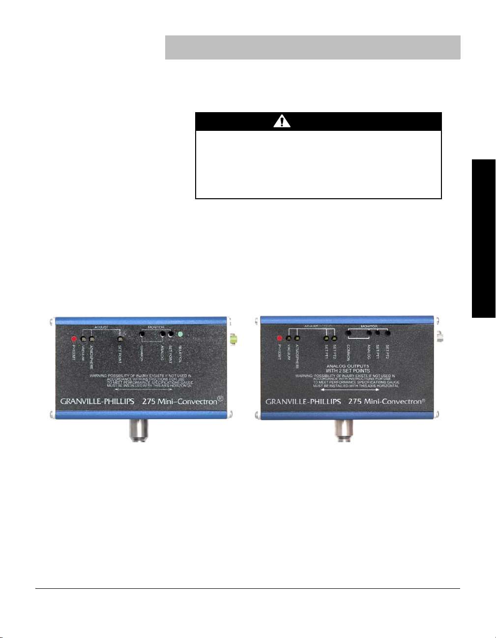
Mini-Convectron module with
one setpoint relay, no display
Mini-Convectron module with
two setpoint relays, no display
2.1 Module Components The Mini-Convectron module contains a Convectron convection-enhanced
Pirani heat-loss gauge.
Using the module to measure the pressure of flammable
or explosive gases can cause a fire or explosion resulting
in severe property damage or personal injury.
Do not use the module to measure the pressure of flammable or
explosive gases.
The module is shipped with an instrument screwdriver and a 15-pin female,
high-density subminiature D connector that mates to the male connector on
the module.
Figure 2-1 illustrates the module without the digital display. The module
without the display may have one setpoint relay or two setpoint relays.
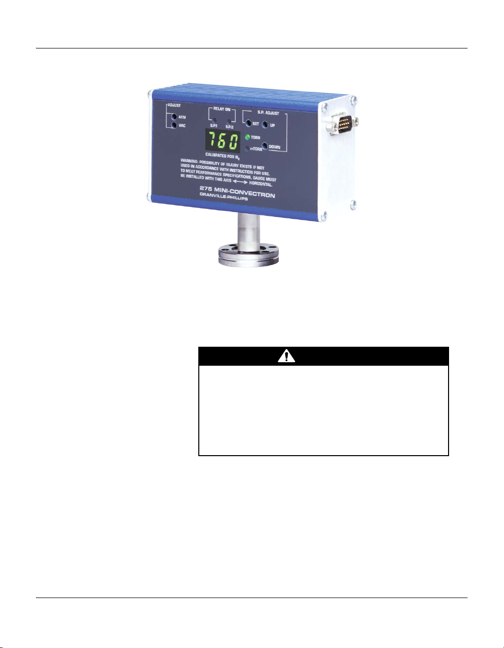
Figure 2-2 illustrates the module with the 3-digit digital display. The module
with the display has two setpoint relays.
Figure 2-1 Mini-Convectron Module without Digital Display
Before You Begin Installation Operation Maintenance
Mini-Convectron Module Instruction Manual - 275512 - Rev. A 11
Chapter 2
CAUTION
Figure 2-2 Mini-Convectron Module with two Setpoint Relays and 3-Digit Digital Display
2.2 Installing Pressure Relief Devices
Before you install the module, install appropriate pressure relief devices in
the vacuum system.
Brooks Automation, Inc. does not supply pressure relief valves or rupture
disks. Suppliers of pressure relief valves and rupture disks are listed in the
Thomas Register under “Valves, Relief” and “Discs, Rupture.”
Operating the module above 1000 Torr (1333 mbar, 133
kPa) true pressure could cause pressure measurement
error or product failure.
To avoid measurement error or product failure due to
overpressurization, install pressure relief valves or rupture
disks in the system if pressure exceeds 1000 Torr (1333 mbar,
133 kPa).
12 Mini-Convectron Module Instruction Manual - 275512 - Rev. A
2.3 Installation Procedure The module installation procedure includes the following steps:
WARNING
1. Locating and orienting the module.
2. Attaching the module vacuum chamber fitting to its mate on the
vacuum chamber.
3. Assembling and connecting module wiring.
4. Configuring the setpoint relays to the desired voltage levels.
5. Calibrating the Convectron gauge at atmospheric and vacuum
pressures.
Failure to use accurate pressure conversion data for N2
or air to other gases can cause an explosion due to
overpressurization.
If the module will measure any gas other than N2 or air, before
putting the module into operation, adjust setpoint relays for the
process gas that will be used.
Step 1 Locate and orient the module
To locate and orient the module, refer to Figure 2-3, Figure 2-4, and
Table 2-1, and follow the instructions below.
Installation
Before You Begin Installation Operation Maintenance
Locate the Module • For greatest accuracy and repeatability, locate the module in a stable,
room-temperature environment. Ambient temperature should never
exceed 40 °C (104 °F) operating, non-condensing, or 85 °C (185 °F)
non-operating.
• Locate the module away from internal and external heat sources and in
an area where ambient temperature remains reasonably constant.
• Do not locate the module where it requires long lengths of tubing or has
constricted tubing. Length of tubing depends on the application. Longer
tubing will affect vacuum pressure limit and response time.
• Do not locate the module near the pump, where gauge pressure might be
lower than normal vacuum chamber pressure.
• Do not locate the module near a gas inlet or other source of
contamination, where inflow of gas or particulates causes atmospheric
pressure to be higher than system atmosphere.
• Do not locate the module where it will be exposed to corrosive gases
such as mercury vapor or fluorine.
• Do not locate the module where it will vibrate. Vibration causes
convection cooling, resulting in inaccurate high pressure readings.
Mini-Convectron Module Instruction Manual - 275512 - Rev. A 13

Chapter 2
11
(4.3)
4.1
(1.6)
6.4
(2.5)
5.5
(2.2)
Dim. H
Figure 2-3 Mini-Convectron Module Dimensions
Table 2-1 Mini-Convectron Vacuum Connections
Vacuum Connections Dim. H
cm in.
1/8 NPT pipe thread, ½-inch inside diameter 2.2 0.9
½-inch 4 VCR
®
type fitting, female 3.0 1.2
½-inch 8 VCR type fitting, female 3.9 1.5
NW16KF flange 3.1 1.2
NW25KF flange 3.1 1.2
NW40KF flange 3.7 1.5
1.33-inch (NW16CF) ConFlat
®
flange 3.8 1.5
2.75-inch (NW35CF) ConFlat flange 3.8 1.5
14 Mini-Convectron Module Instruction Manual - 275512 - Rev. A
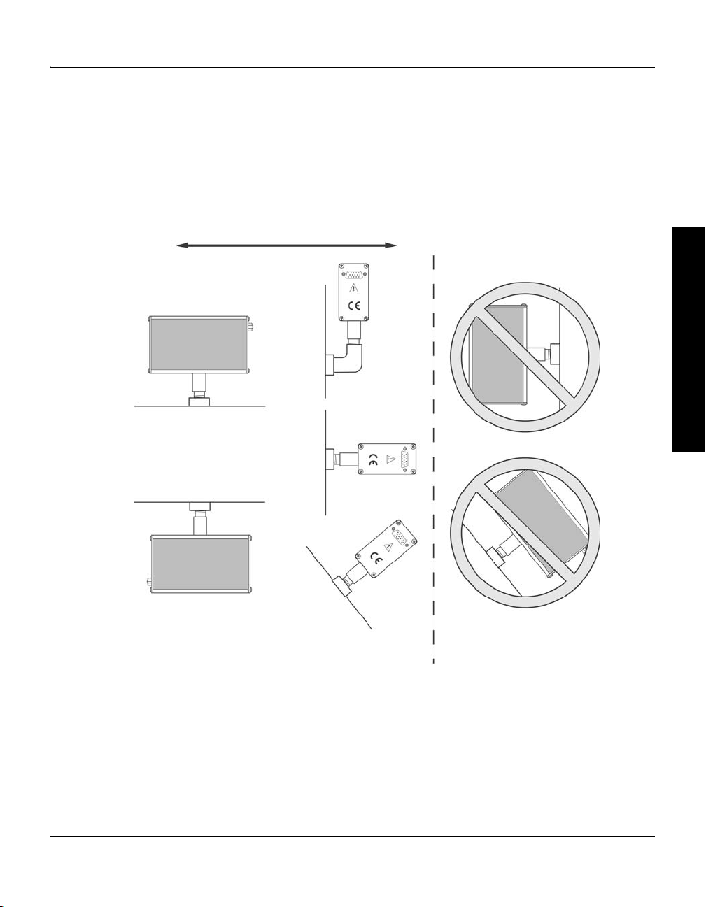
Orient the Module For proper operation of the module above 1 Torr, orient the module so the
Mount the Module Axis Horizontally to Ensure
Accurate Measurement Above 1 Torr
Vacuum chamber
Vacuum chamber
Vacuum chamberVacuum chamber
V
a
c
u
u
m
c
h
a
m
b
e
r
V
a
c
u
u
m
Vacuum
Recommended Not recommended
Figure 2-4 Module Orientation
Installation
Before You Begin Installation Operation Maintenance
axis is horizontal (see Figure 2-4). Although the Convectron gauge will read
correctly below 1 Torr with the module mounted in any position, inaccurate
readings will result at pressures above 1 Torr if the module axis is not
horizontal.
Mini-Convectron Module Instruction Manual - 275512 - Rev. A 15
Chapter 2
CAUTION
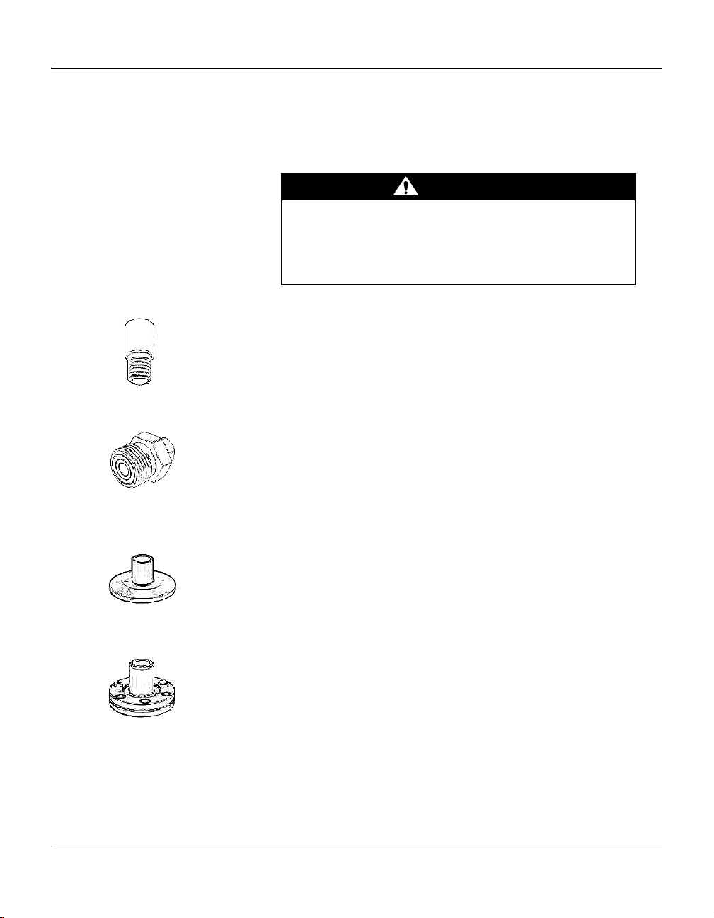
Step 2 Attach the module to the vacuum chamber
Attach the module vacuum chamber fitting to its mate on the vacuum
chamber.
Twisting the module to tighten the fitting to the vacuum
chamber can damage the module’s internal connections.
• Do not twist the module to tighten the fitting.
• Use appropriate tools to tighten the fitting.
1/8 NPT pipe thread The 1/8 NPT pipe thread accommodates a standard 1/8 NPT female fitting.
a. Wrap the threads of the port to the vacuum chamber with thread seal
tape.
b. Without using a wrench or other tool, tighten the module just enough
to achieve a seal.
VCR type fitting a. Remove the plastic or metal bead protector cap from the fitting.
b. If a gasket is used, place the gasket into the female nut.
c. Assemble the components and tighten them to finger-tight.
d. While holding a back-up wrench stationary, tighten the female nut 1/8
turn past finger-tight on 316 stainless steel or nickel gaskets, or 1/4 turn
past finger-tight on copper or aluminum gaskets.
KF flange The KF mounting system requires O-rings and centering rings between
mating flanges.
a. Tighten the clamp to compress the mating flanges together.
b. Seal the O-ring.
ConFlat flange To minimize the possibility of leaks with ConFlat flanges, use high strength
stainless steel bolts and a new, clean OFHC copper gasket. Avoid
scratching the seal surfaces. To avoid contamination, install metal gaskets.
a. Finger tighten all bolts.
b. Use a wrench to continue tightening 1/8 turn at a time in crisscross
order (1, 4, 2, 5, 3, 6) until flange faces make contact.
c. Further tighten each bolt about 1/16 turn.
16 Mini-Convectron Module Instruction Manual - 275512 - Rev. A

Step 3 Assemble and connect the wiring
Analog output 5
Power ground 4
11.5–26.5 VDC power input 3
Setpoint 2 adjust 2
Setpoint 1 adjust 1
15 Relay 1 common
14 Relay 1 normally closed
13 Relay 2 normally closed
12 Relay 2 common
11 Relay 2 normally open
10 Relay 1 normally open
9 Relay disable
8 No connection
7 No connection
6 Signal common
Analog output 5
Power ground 4
11.5–26.5 VDC power input 3
Relay normally closed 2
Relay normally open 1
9 Setpoint output
8 Signal common
7 Relay disable
6 Relay common
Connecting Cable The cable is user-supplied. Brooks Automation does not supply the cable.
Install externally shielded cable and connect the shield at both ends.
At the module end of the cable, connect the shield to the outer shell of the
subminiature D connector.
On both versions of the module, connect the 11.5 to 26.5 Vdc power
supply to terminals 3 and 4.
• Terminal 4 (ground) is negative (–).
• Terminal 3 (input) is positive (+).
For grounding instructions, see page 18.
Wiring Terminals Figure 2-5 illustrates the 15-pin D subminiature wiring terminals for the
module with two setpoint relays.
Figure 2-6 illustrates the 9-pin D subminiature wiring terminals for the
module with one setpoint relay.
Figure 2-5 15-Pin Connector for Module with two Setpoint Relays
Installation
Before You Begin Installation Operation Maintenance
Figure 2-6 9-Pin Connector for Module with one Setpoint Relay
Mini-Convectron Module Instruction Manual - 275512 - Rev. A 17
Chapter 2
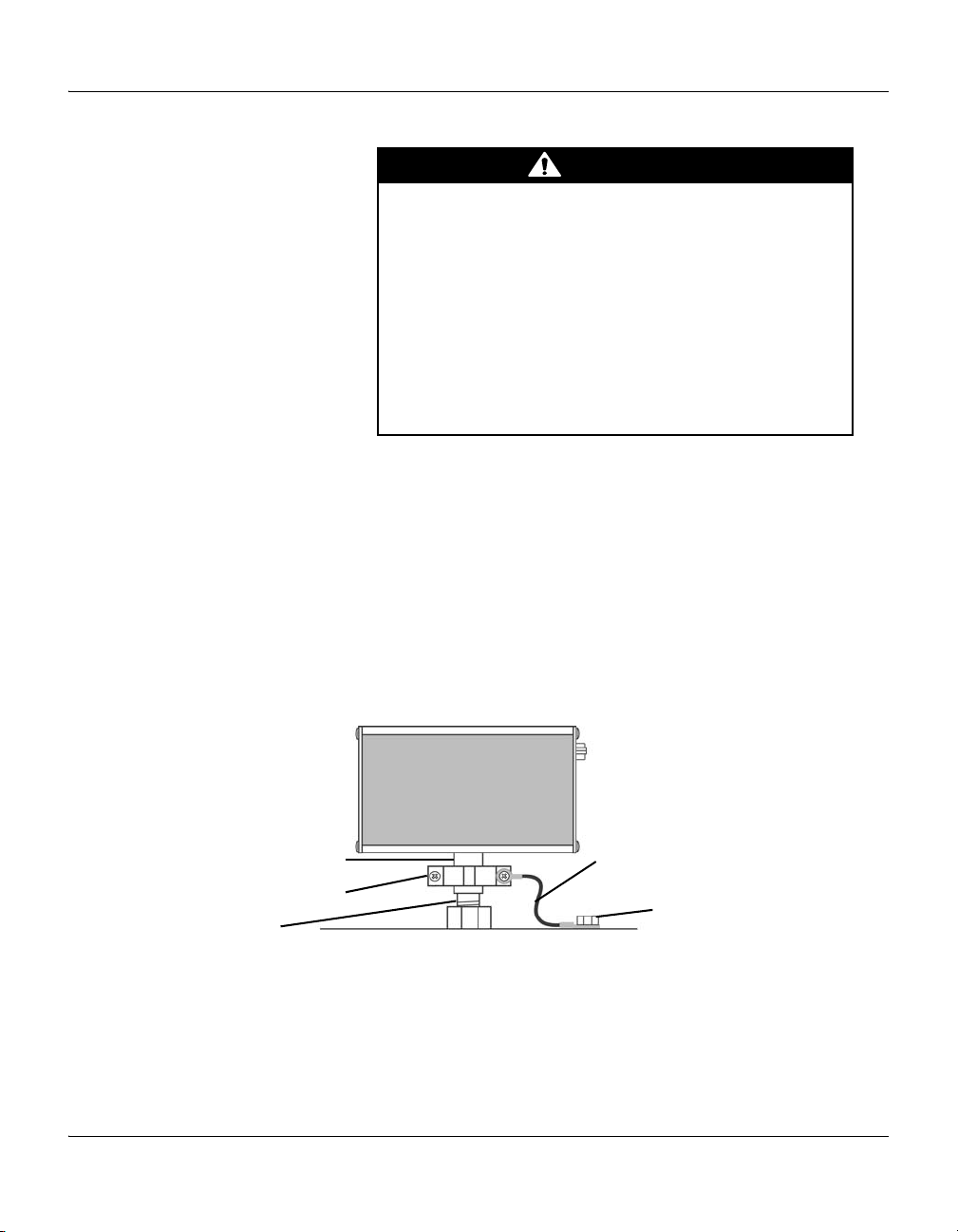
WARNING
Metal hose clamp or other metal clamp
3.00 mm
2
(12 AWG) or larger ground wire
Fitting
Vacuum Chamber
Ground lug, bolt, or stud
Gauge stem
Grounding
Improper grounding could cause product failure,
property damage, or serious personal injury.
To reduce the risk of product failure, property damage, or
serious personal injury, follow ground network requirements
for the facility.
• Maintain all exposed conductors at earth ground.
• Ground the module housing to the vacuum chamber as
instructed below.
• Make sure the vacuum port to which the module is mounted
is properly grounded.
If the fitting allows continuous metal-to-metal contact between the housing
base and the vacuum chamber, the module is properly grounded via the
fitting. If the fitting requires a rubber gasket, rubber O-ring, Teflon tape, or
other material that prevents metal-to-metal contact between the housing
base and the vacuum chamber, refer to Figure 2-7 and follow these
instructions to ground the module to the vacuum chamber:
a. Attach a metal hose clamp or other metal clamp to the gauge stem of
the housing.
2
b. Install a 3.31 mm
(12 AWG) or larger copper wire between the clamp
and a metal ground lug, bolt, or stud on the vacuum chamber.
Figure 2-7 Ground Connection to the Vacuum Chamber
18 Mini-Convectron Module Instruction Manual - 275512 - Rev. A
Installation
WARNING
Step 4 Configure the setpoint relays for the application
To configure setpoint relays for the module, see pages 34–41.
If the module will measure the pressure of a gas other than N
or air, you
2
must adjust relay setpoints for the process gas. The true pressure of a gas
other than N2 or air may be substantially different from the pressure that the
output indicates. For example, outputs might indicate a pressure of 10 Torr
(1.33 kPa, 13.3 mbar) for argon, although the true pressure of the argon is
250 Torr (33.3 kPa, 333.3 mbar). Such a substantial difference between
indicated pressure and true pressure can cause overpressurization resulting
in an explosion.
Failure to use accurate pressure conversion data for N2
or air to other gases can cause an explosion due to
overpressurization.
If the module will measure any gas other than N2 or air, before
connecting relays to system control devices, adjust setpoints for
the process gas that will be used.
Step 5 Calibrate the Convectron gauge
Before You Begin Installation Operation Maintenance
Calibration improves the accuracy and repeatability of the Convectron
gauge. To calibrate the Convectron gauge, see pages 42–44.
Atmospheric Pressure Calibration
An atmospheric calibration is performed on the Convectron gauge, using
, at the factory before the module is shipped. The factory calibration sets
N
2
the atmospheric calibration point to 760 Torr (101.3 kPa, 1013 mbar) of N2.
Because performance varies depending on the process gas, you may wish
to reset the atmospheric calibration point if a gas other than N
or air is
2
being used. Periodic resets of the atmospheric calibration point also
improve the accuracy and repeatability of the Convectron gauge near
atmospheric pressure, even if the process gas is N
Vacuum Chamber Pressure Calibration
Mini-Convectron Module Instruction Manual - 275512 - Rev. A 19
Periodic resets of the vacuum chamber pressure calibration point improve
the accuracy and repeatability of the Convectron gauge.
or air.
2

20 Mini-Convectron Module Instruction Manual - 275512 - Rev. A
 Loading...