

Granville-Phillips Series 354 Instruction Manual

Series 354
Granville-Phillips® Series 354 Micro-Ion
Vacuum Gauge Module with
RS-485 Digital Interface
®
Instruction Manual
Instruction manual part number 354008
Revision C - September 2014


Series 354
Granville-Phillips® Series 354 Micro-Ion
®
Vacuum Gauge Module with
RS-485 Digital Interface
This instruction manual is for use with Granville-Phillips
Series 354 Micro-Ion Vacuum Gauge Modules with
RS-485 Digital Interface. A list of applicable catalog
numbers is provided on the following page.
For Customer Service or Technical Support 24 hours per day,
7 days per week, every day of the year including holidays:
Phone: +1-800-227-8766 or +1-303-652-4691
MKS, Granville-Phillips Division
6450 Dry Creek Parkway
Longmont, CO 80503 USA
Phone: 1-303-652-4691 or 1-800-776-6543
FAX: 1-303-652-2844
Email: gp-csr@mksinst.com
Corporate Office
MKS Instruments, Inc.
2 Tech Drive, Suite 201
Andover, MA 01810 USA
Phone: 1-978-645-5500
www.mksinst.com
Instruction Manual
© 2014 MKS Instruments, Inc. All rights reserved.
Granville-Phillips
All other trademarks and registered trademarks are the properties of their respective owners.
®
and Micro-Ion® are registered trademarks of MKS Instruments, Inc.

Granville-Phillips® Series 354 Micro-Ion
®
Vacuum Gauge Module with RS-485 Digital Interface
Catalog numbers for Series 354 Micro-Ion Modules
Power supply and cable are not included.
RS-485 interface, 1 setpoint relay:
Same as 354005, but with Varian Syntax (Torr only)
RS-485 interface, 1 setpoint relay:
Same as 354005, but with 90 Degree elbow (Torr only) 20
RS-485 interface, 1 setpoint relay:
No digital display (Torr Only
Filaments:
dual yttria-coated iridium Y
dual tungsten T
Flange/Fitting:
NW16KF D
NW25KF E
NW40KF K
1.33 inch (NW16CF) Conflat-type F
2.75 inch (NW35CF) Conflat-type G
1/2 inch VCR-type male H
NW16KFL M
NW40KFL L
NW25KFL N
354029 - Y E - T
354017
354005 - X X - T

Table of Contents
Chapter 1 General Information . . . . . . . . . . . . . . . . . . . . . . . . . . . . . . . . . . . . . . . . . . . . . . . . . . . . . . . . . . . . . . . . . 7
1.1 Receiving Inspection . . . . . . . . . . . . . . . . . . . . . . . . . . . . . . . . . . . . . . . . . . . . . . . . . . . . . . . . . . . . . . . . . 7
1.2 International Shipment . . . . . . . . . . . . . . . . . . . . . . . . . . . . . . . . . . . . . . . . . . . . . . . . . . . . . . . . . . . . . . . 7
1.3 Warranty . . . . . . . . . . . . . . . . . . . . . . . . . . . . . . . . . . . . . . . . . . . . . . . . . . . . . . . . . . . . . . . . . . . . . . . . . . 7
1.4 Certification . . . . . . . . . . . . . . . . . . . . . . . . . . . . . . . . . . . . . . . . . . . . . . . . . . . . . . . . . . . . . . . . . . . . . . . . 7
1.5 Service Guidelines . . . . . . . . . . . . . . . . . . . . . . . . . . . . . . . . . . . . . . . . . . . . . . . . . . . . . . . . . . . . . . . . . . . 8
1.6 FCC Verification . . . . . . . . . . . . . . . . . . . . . . . . . . . . . . . . . . . . . . . . . . . . . . . . . . . . . . . . . . . . . . . . . . . . 8
Chapter 2 Safety . . . . . . . . . . . . . . . . . . . . . . . . . . . . . . . . . . . . . . . . . . . . . . . . . . . . . . . . . . . . . . . . . . . . . . . . . . . . . 9
2.1 Safety Introduction . . . . . . . . . . . . . . . . . . . . . . . . . . . . . . . . . . . . . . . . . . . . . . . . . . . . . . . . . . . . . . . . . . 9
2.2 Grounding Requirements . . . . . . . . . . . . . . . . . . . . . . . . . . . . . . . . . . . . . . . . . . . . . . . . . . . . . . . . . . . . . 11
2.3 High Voltage . . . . . . . . . . . . . . . . . . . . . . . . . . . . . . . . . . . . . . . . . . . . . . . . . . . . . . . . . . . . . . . . . . . . . . 11
2.4 Over-Pressure Conditions . . . . . . . . . . . . . . . . . . . . . . . . . . . . . . . . . . . . . . . . . . . . . . . . . . . . . . . . . . . . 12
2.5 System and Environment . . . . . . . . . . . . . . . . . . . . . . . . . . . . . . . . . . . . . . . . . . . . . . . . . . . . . . . . . . . . . 12
2.6 Responsibility . . . . . . . . . . . . . . . . . . . . . . . . . . . . . . . . . . . . . . . . . . . . . . . . . . . . . . . . . . . . . . . . . . . . . . 13
2.7 Damage Requiring Service . . . . . . . . . . . . . . . . . . . . . . . . . . . . . . . . . . . . . . . . . . . . . . . . . . . . . . . . . . . . 14
Chapter 3 Introduction . . . . . . . . . . . . . . . . . . . . . . . . . . . . . . . . . . . . . . . . . . . . . . . . . . . . . . . . . . . . . . . . . . . . . . 15
3.1 General Description . . . . . . . . . . . . . . . . . . . . . . . . . . . . . . . . . . . . . . . . . . . . . . . . . . . . . . . . . . . . . . . . . 15
3.2 Dimensions . . . . . . . . . . . . . . . . . . . . . . . . . . . . . . . . . . . . . . . . . . . . . . . . . . . . . . . . . . . . . . . . . . . . . . . 15
3.3 Specifications . . . . . . . . . . . . . . . . . . . . . . . . . . . . . . . . . . . . . . . . . . . . . . . . . . . . . . . . . . . . . . . . . . . . . . 16
3.4 Power Supply Requirements . . . . . . . . . . . . . . . . . . . . . . . . . . . . . . . . . . . . . . . . . . . . . . . . . . . . . . . . . . . 17
3.5 Component Description . . . . . . . . . . . . . . . . . . . . . . . . . . . . . . . . . . . . . . . . . . . . . . . . . . . . . . . . . . . . . 18
3.5.1 Power Indicator Lamp . . . . . . . . . . . . . . . . . . . . . . . . . . . . . . . . . . . . . . . . . . . . . . . . . . . . . . . . . 18
3.5.2 Address Selector Switch . . . . . . . . . . . . . . . . . . . . . . . . . . . . . . . . . . . . . . . . . . . . . . . . . . . . . . . . 18
3.5.3 Input/Output Connector . . . . . . . . . . . . . . . . . . . . . . . . . . . . . . . . . . . . . . . . . . . . . . . . . . . . . . . 18
3.5.4 Mounting Flange . . . . . . . . . . . . . . . . . . . . . . . . . . . . . . . . . . . . . . . . . . . . . . . . . . . . . . . . . . . . . 19
3.6 Theory of Operation . . . . . . . . . . . . . . . . . . . . . . . . . . . . . . . . . . . . . . . . . . . . . . . . . . . . . . . . . . . . . . . . 19
3.7 Emission Current . . . . . . . . . . . . . . . . . . . . . . . . . . . . . . . . . . . . . . . . . . . . . . . . . . . . . . . . . . . . . . . . . . . 20
3.8 Overpressure Shutdown . . . . . . . . . . . . . . . . . . . . . . . . . . . . . . . . . . . . . . . . . . . . . . . . . . . . . . . . . . . . . . 20
3.9 Degas Cycle . . . . . . . . . . . . . . . . . . . . . . . . . . . . . . . . . . . . . . . . . . . . . . . . . . . . . . . . . . . . . . . . . . . . . . . 20
Chapter 4 Installation and Configuration . . . . . . . . . . . . . . . . . . . . . . . . . . . . . . . . . . . . . . . . . . . . . . . . . . . . . . . . . 21
4.1 Introduction . . . . . . . . . . . . . . . . . . . . . . . . . . . . . . . . . . . . . . . . . . . . . . . . . . . . . . . . . . . . . . . . . . . . . . . 21
4.2 Grounding . . . . . . . . . . . . . . . . . . . . . . . . . . . . . . . . . . . . . . . . . . . . . . . . . . . . . . . . . . . . . . . . . . . . . . . . 21
4.3 I/O Cable Connections . . . . . . . . . . . . . . . . . . . . . . . . . . . . . . . . . . . . . . . . . . . . . . . . . . . . . . . . . . . . . . 21
4.4 Installation . . . . . . . . . . . . . . . . . . . . . . . . . . . . . . . . . . . . . . . . . . . . . . . . . . . . . . . . . . . . . . . . . . . . . . . . 23
4.4.1 Firmware Configuration . . . . . . . . . . . . . . . . . . . . . . . . . . . . . . . . . . . . . . . . . . . . . . . . . . . . . . . . 24
4.4.1.1 Resetting the Data Communication Parameters . . . . . . . . . . . . . . . . . . . . . . . . . . . . . . 25
4.5 Calculating a Gas Sensitivity Correction . . . . . . . . . . . . . . . . . . . . . . . . . . . . . . . . . . . . . . . . . . . . . . . . . 26
4.6 Very-High and Ultra-High Vacuum Measurement . . . . . . . . . . . . . . . . . . . . . . . . . . . . . . . . . . . . . . . . . 26
4.6.1 Micro-Ion Vacuum Gauge Module Process Chamber Baking . . . . . . . . . . . . . . . . . . . . . . . . . . . 27
Chapter 5 RS-485 Digital Interface Specifications and Protocol . . . . . . . . . . . . . . . . . . . . . . . . . . . . . . . . . . . . . . . 29
5.1 Introduction . . . . . . . . . . . . . . . . . . . . . . . . . . . . . . . . . . . . . . . . . . . . . . . . . . . . . . . . . . . . . . . . . . . . . . . 29
5.2 Interface Configuration . . . . . . . . . . . . . . . . . . . . . . . . . . . . . . . . . . . . . . . . . . . . . . . . . . . . . . . . . . . . . . 29
5.3 Receive/Transmit Timing . . . . . . . . . . . . . . . . . . . . . . . . . . . . . . . . . . . . . . . . . . . . . . . . . . . . . . . . . . . . 34
Chapter 6 Troubleshooting . . . . . . . . . . . . . . . . . . . . . . . . . . . . . . . . . . . . . . . . . . . . . . . . . . . . . . . . . . . . . . . . . . . 37
6.1 Introduction . . . . . . . . . . . . . . . . . . . . . . . . . . . . . . . . . . . . . . . . . . . . . . . . . . . . . . . . . . . . . . . . . . . . . . . 37
6.2 Troubleshooting Procedures . . . . . . . . . . . . . . . . . . . . . . . . . . . . . . . . . . . . . . . . . . . . . . . . . . . . . . . . . . . 37
Chapter 7 Service . . . . . . . . . . . . . . . . . . . . . . . . . . . . . . . . . . . . . . . . . . . . . . . . . . . . . . . . . . . . . . . . . . . . . . . . . . . 39
7.1 Introduction . . . . . . . . . . . . . . . . . . . . . . . . . . . . . . . . . . . . . . . . . . . . . . . . . . . . . . . . . . . . . . . . . . . . . . . 39
7.2 Micro-Ion Vacuum Gauge (with Digital Interface) Module Initialization . . . . . . . . . . . . . . . . . . . . . . . . 39
7.2.1 Initialization . . . . . . . . . . . . . . . . . . . . . . . . . . . . . . . . . . . . . . . . . . . . . . . . . . . . . . . . . . . . . . . . . 39
7.3 Degas Cycle . . . . . . . . . . . . . . . . . . . . . . . . . . . . . . . . . . . . . . . . . . . . . . . . . . . . . . . .
Digital Interface . . . . . . . . . . . . . . . . . . . . . . . . . . . . . . . . . . . . . . . . . . . . . . . . . . . . . . . . . . . . . . 41
7.3.1
7.4 Fuse Replacement . . . . . . . . . . . . . . . . . . . . . . . . . . . . . . . . . . . . . . . . . . . . . . . . . . . . . . . . . . . . . . . . . . 41
. . . . . . . . . . . . . . . 41
Series 354 Micro-Ion Vacuum Gauge Module
Instruction Manual - 354008 - Rev. C
5

7.5 Micro-Ion Gauge Replacement . . . . . . . . . . . . . . . . . . . . . . . . . . . . . . . . . . . . . . . . . . . . . . . . . . . . . . . . 42
7.6 Ion Gauge Continuity Test . . . . . . . . . . . . . . . . . . . . . . . . . . . . . . . . . . . . . . . . . . . . . . . . . . . . . . . . . . . 44
7.7 Service Guidelines . . . . . . . . . . . . . . . . . . . . . . . . . . . . . . . . . . . . . . . . . . . . . . . . . . . . . . . . . . . . . . . . . . 46
6
Series 354 Micro-Ion Vacuum Gauge Module
Instruction Manual - 354008 - Rev. C

1 General Information
Chapter 1
1General Information
1.1 Receiving Inspection
On receipt of the equipment, inspect all material for damage. Confirm that the shipment includes
all items ordered. If items are missing or damaged, submit a claim as stated below for a domestic or
international shipment, whichever is applicable.
If materials are missing or damaged, the carrier that made the delivery must be notified within 15
days of delivery, or in accordance with Interstate Commerce regulations for the filing of a claim.
Any damaged material including all containers and packaging should be held for carrier inspection.
Contact MKS, Granville-Phillips Division Customer Support for assistance if your shipment is not
correct for reasons other than shipping damage.
1.2 International Shipment
Inspect all materials received for shipping damage and confirm that the shipment includes all items
ordered. If items are missing or damaged, the airfreight forwarder or airline making delivery to the
customs broker must be notified within 15 days of delivery.The following illustrates to whom the
claim is to be directed.
• If an airfreight forwarder handles the shipment and their agent delivers the shipment to customs,
the claim must be filed with the airfreight forwarder.
• If an airfreight forwarder delivers the shipment to a specific airline and the airline delivers the
shipment to customs, the claim must be filed with the airline.
Any damaged material including all containers and packaging should be held for carrier inspection.
Contact Granville-Phillips Customer Support for assistance if your shipment is not correct for
reasons other than shipping damage.
1.3 Warranty
MKS Instruments, Inc. provides an eighteen (18) month warranty from the date of shipment for new
Granville-Phillips Products. The MKS General Terms and Conditions of Sale provides the complete
and exclusive warranty for Granville-Phillips products. This document may be located on our web
site at www.mksinst.com, or may be obtained by contacting a Granville-Phillips Customer Service
Representative.
1.4 Certification
MKS Instruments, Inc. certifies that this product met its published specifications at the time of
shipment from the factory. MKS Instruments, Inc. further certifies that its calibration measurements
are traceable to the National Institute of Standards and Technology to the extent allowed by the
Institute's calibration facility.
Series 354 Micro-Ion Vacuum Gauge Module
Instruction Manual - 354008 - Rev. C
7

1 General Information
1.5 Service Guidelines
Some minor problems are readily corrected on site. If the product requires service, contact the MKS,
Granville-Phillips Division Customer Service Department at +1-800-227-8766 or +1-303-652-4691
for troubleshooting help over the phone.
If the product must be returned to the factory for service, request a Return Material Authorization
(RMA) from Granville-Phillips. Do not return products without first obtaining an RMA. In some
cases a hazardous materials document may be required. The MKS/Granville-Phillips Customer
Service Representative will advise you if the hazardous materials document is required.
When returning a products to Granville-Phillips, be sure to package the products to prevent
shipping damage. Circuit boards and modules separated from the gauge assembly must be handled
using proper anti-static protection methods and must be packaged in anti-static packaging.
Granville-Phillips will supply return packaging materials at no charge upon request. Shipping
damage on returned products as a result of inadequate packaging is the Buyer's responsibility.
For Customer Service or Technical Support 24 hours per day, 7 days per week, every day of the year
including holidays:
Phone: +1-800-227-8766 or +1-303-652-4691
Email: gp-csr@mksinst.com
MKS, Granville-Phillips Division
6450 Dry Creek Parkway
Longmont, CO 80503 USA
Phone: 1-303-652-4691 or 1-800-776-6543
FAX: 1-303-652-2844
1.6 FCC Verification
This equipment was tested and complies with the limits for a Class A digital device, pursuant to Part
15 of the FCC Rules. These limits are designed to provide reasonable protection against harmful
interference when the equipment is operated in a commercial environment. This equipment
generates, uses, and can radiate radio frequency energy and, if not installed and used in accordance
with this instruction manual, may cause harmful interference to radio communications. However,
there is no guarantee that interference will not occur in a particular installation.
Operation of this equipment in a residential area is likely to cause harmful interference in which
case the user will be required to correct the interference at his own expense. If this equipment does
cause harmful interference to radio or television reception, which can be determined by turning the
equipment off and on, the user is encouraged to try to correct the interference by one or more of the
following measures:
• Reorient or relocate the receiving antenna.
• Increase the separation between the equipment and the receiver.
• Connect the equipment into an outlet on a circuit different from that to which the receiver is
connected.
• Consult the dealer or an experienced radio or television technician for help.
8
Series 354 Micro-Ion Vacuum Gauge Module
Instruction Manual - 354008 - Rev. C
2 Safety
Chapter 2
2Safety
2.1 Safety Introduction
START BY READING THESE IMPORTANT SAFETY INSTRUCTIONS AND NOTES collected here
for your convenience and repeated with additional information at appropriate points throughout
this instruction manual.
These safety alert symbols in this manual or on the Product mean caution - personal safety, property
damage or danger from electric shock. Read these instructions carefully.
Danger indicates a hazardous situation which, if not
avoided, will result in death or serious injury.
Warning indicates a hazardous situation which, if not
avoided, could result in death or serious injury.
Caution indicates a hazardous situation or unsafe
practice which, if not avoided, may result in minor or
moderate personal injury.
Indicates a situation or unsafe practice which, if not
avoided, may result in equipment damage.
Notice
These instructions do not and cannot provide for every contingency that
may arise in connection with the installation, operation, or maintenance of
this product. If you require further assistance, contact Granville-Phillips at
the address on the title page of this instruction manual.
This product was designed and tested to offer reasonably safe service provided it is installed,
operated, and serviced in strict accordance with these safety instructions.
Safety Precautions
Failure to comply with these instructions may result in serious
personal injury, including death, or property damage.
Always observe and follow all safety notices that are
provided throughout this instruction manual and on the
product.
Series 354 Micro-Ion Vacuum Gauge Module
Instruction Manual - 354008 - Rev. C
9
2 Safety
These safety precautions must be observed during all phases of operation, installation, and service
of this product. Failure to comply with these precautions or with specific warnings elsewhere in this
manual violates safety standards of design, manufacture, and intended use of the instrument. MKS
Instruments, Inc. disclaims all liability for the customer's failure to comply with these requirements.
• Read Instructions – Read all safety and operating instructions before operating the product.
• Retain Instructions – Retain the Safety and Operating Instructions for future reference.
• Heed Warnings – Adhere to all warnings on the product and in the operating instructions.
• Follow Instructions – Follow all operating and maintenance instructions.
• Accessories – Do not use accessories not recommended in this manual as they may be
hazardous.
Electrical Shock or Personal Injury
The service and repair information in this manual is for the use
of Qualified Service Personnel. To avoid possible electrical
shock or personal injury, do not perform any procedures in
this manual or perform any servicing on this product unless
you are qualified to do so.
Electrical Shock or Fire
To reduce the risk of fire or electric shock, do not expose this
product to rain or moisture.
Objects and Liquid Entry - Never push objects of any kind into
this product through openings as they may touch dangerous
voltage points or short out parts that could result in a fire or
electric shock. Be careful not to spill liquid of any kind onto the
products.
10
Series 354 Micro-Ion Vacuum Gauge Module
Instruction Manual - 354008 - Rev. C
2 Safety
2.2 Grounding Requirements
See Grounding, Section 4.2 in the Installation chapter for more detailed requirements regarding
gauge and system grounding.
Proper Grounding
All components of a vacuum system used with this or any
similar high voltage product must be maintained at Earth
ground for safe operation.
Be aware that grounding this product does not guarantee that
other components of the vacuum system are maintained at
Earth ground.
Verify that the vacuum port to which the Series 354 Micro-Ion
Gauge is mounted is electrically grounded. It is essential for
personnel safety as well as proper operation that the
envelope of the gauge be connected to a facility ground. See
Section 4.2 for detailed grounding instructions.
Connect power cords only to properly grounded outlets or
sources.
2.3 High Voltage
High Voltage is present in the Micro-Ion Gauge Module when the module is powered ON.
Hazardous voltages may still be present in the module for some time after disconnecting power to
the module. Refer to the Installation and Service chapters for more information.
High Voltage
Be aware that when high voltage is present in any vacuum
system, a life threatening electrical shock hazard may exist
unless all exposed conductors are maintained at Earth ground.
This hazard is not unique to this product.
High Voltage
All conductors in, on, or around the vacuum system that are
exposed to potential high voltage electrical discharges must
either be shielded at all times to protect personnel or must be
connected to Earth ground at all times.
Ion producing equipment, such as ionization gauges, mass
spectrometers, sputtering systems, etc., may under some
conditions provide sufficient conduction via a plasma to couple
a high voltage electrode to the vacuum chamber. If conductive
parts of the chamber are not grounded, they may attain a
potential near that of the high voltage electrode during this
coupling.
Series 354 Micro-Ion Vacuum Gauge Module
Instruction Manual - 354008 - Rev. C
11
2 Safety
Be aware that an electrical discharge through a gas may
couple dangerous high voltage directly to an ungrounded
conductor almost as effectively as would a copper wire
connection. A person may be seriously injured or even killed
by merely touching an exposed ungrounded conductor at high
potential.
This hazard is not unique to this product.
2.4 Over-Pressure Conditions
Install suitable devices that will limit the pressure to the level the
vacuum system can safely withstand. In addition, install
suitable pressure relief valves or rupture disks that will release
pressure at a level considerably below the pressure that the
system can safely withstand.
High Voltage
Over-Pressure Conditions
Suppliers of pressure relief valves and pressure relief disks can be located via an online search, and
are listed in the Thomas Register under “Valves, Relief”, and “Discs, Rupture”. Confirm that these
safety devices are properly installed before installing the product.
Ensure the following precautions are complied with at all times:
(1) the proper gas cylinders are installed
(2) the gas cylinder valve positions are correct on manual systems
(3) the automation is correct on automated gas delivery systems
Vacuum gauges with compression fittings may be forcefully ejected if the vacuum system is
pressurized.
2.5 System and Environment
Explosive Environment
Do not use the Series 354 Micro-Ion Gauge in an environment
of explosive or combustible gases or gas mixtures. Operation
of any electrical instrument in such an environment constitutes
a definite safety hazard. Do not use the product to measure
the pressure of explosive gases or gas mixtures.
12
Series 354 Micro-Ion Vacuum Gauge Module
Instruction Manual - 354008 - Rev. C

Chemical Fumes / Explosive Environment
The fumes from solvents such as trichloroethylene,
perchloroethylene, toluene, and acetone can be dangerous to
health if inhaled. Use only in well ventilated areas exhausted
to the outdoors.
Acetone and toluene are highly flammable and should not be
used near an open flame or energized electrical equipment.
Potential Automatic Operation
It is the installer's responsibility to ensure that the automatic
signals provided by the product are always used in a safe
manner. Carefully check the system programming before
switching to automatic operation.
2 Safety
Vacuum Chamber High Pressures
Where an equipment malfunction could cause a hazardous
situation, always provide for fail-safe operation. As an
example, in an automatic backfill operation where a
malfunction might cause high internal pressures, provide an
appropriate pressure relief device.
2.6 Responsibility
It is the responsibility of the Customer to comply with all local, state, and federal ordinances,
regulations, and laws applicable to the installation, operation and service of this equipment.
It is the responsibility of the end user to provide sufficient lighting at work to meet local regulations.
Operation and Service of this equipment in strict accordance with the methods and procedures
supplied by MKS, Granville-Phillips Division is the responsibility of the Customer.
MKS Instruments, Inc. assumes no liability, whatsoever, for any personal injuries or damages
resulting from the operation or service of this equipment in any manner inconsistent or contrary to
the methods supplied in Granville-Phillips literature including, but not limited to, manuals,
instructions, bulletins, communications, and recommendations.
For emergencies and for product safety related matters, contact Granville-Phillips Customer Service
Department. See Section 1.5 or Section 7.7 for detailed information regarding how to contact
Granville-Phillps Customer Service Representatives.
Series 354 Micro-Ion Vacuum Gauge Module
Instruction Manual - 354008 - Rev. C
13
2 Safety
2.7 Damage Requiring Service
Disconnect the product from all power sources and refer servicing to Qualified Service Personnel
under the following conditions:
a. When any cable or plug is damaged.
b. If any liquid has been spilled onto, or objects have fallen into the product.
c. If the product has been exposed to rain or water.
d. If the product does not operate normally even if you follow the operating instructions.
Adjust only those controls that are covered by the operation instructions. Improper
adjustment of other controls may result in damage and will often require extensive work
by a qualified technician to restore the product to its normal operation.
e. If the product has been dropped or the enclosure has been damaged.
f. When the product exhibits a distinct change in performance. This indicates a need for
service.
Notice
Do not substitute parts or modify the instrument.
Because of the danger of introducing additional hazards, do not install
substitute parts or perform any unauthorized modification to the product.
Return the product to a service facility designated by Granville-Phillips for
service and repair to ensure that safety features are maintained. Do not use
this product if it has unauthorized modifications.
Notice
Safety Check - Upon completion of any service or repairs to this product,
ask the Qualified Service Person to perform safety checks to determine that
the product is in safe operating order.
Notice
Finite Lifetime - After ten years of normal use or even non-use, the electrical
insulation in this product may become less effective at preventing electrical
shock. Under certain environmental conditions which are beyond the
manufacturer’s control, some insulation material may deteriorate sooner.
Therefore, periodically inspect all electrical insulation for cracks, crazing, or
other signs of deterioration. Do not use if the electrical insulation has
become unsafe.
14
Series 354 Micro-Ion Vacuum Gauge Module
Instruction Manual - 354008 - Rev. C
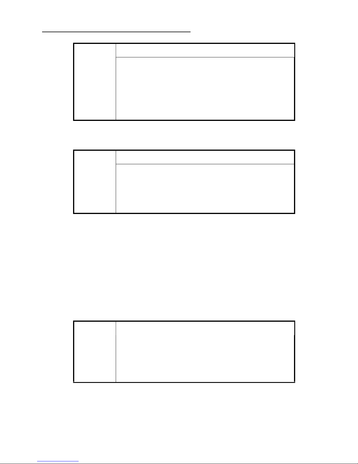
3.1 General Description
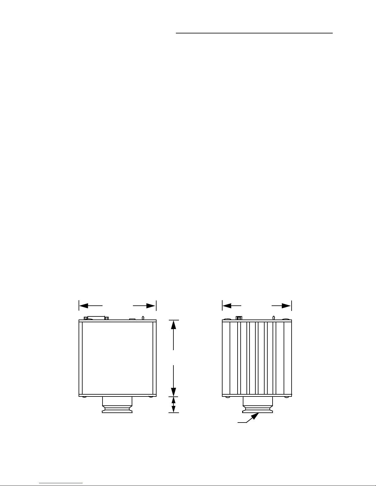
2.80 in
(71.12 mm)
3.00 in
(76.20 mm)
MOUNTING FLANGE
2.60 in
(66.04 mm)
See Dimension H
on Table 3-1
3 Introduction
Chapter 3
3Introduction
The Model 354 Micro-Ion Vacuum Gauge Module, shown in Figure 3-1, is a modular instrument
-9
that is capable of measuring vacuum pressures from 1 x 10
Torr to 5 x 10⁻² Torr - N2 equivalent (or
air).
The 354 Micro-Ion Vacuum Gauge Module is a small rugged unit that has a wider measurement
range, more burnout resistance, and generates less heat than typical glass gauges. Additional
benefits include:
• Compact, Convenient, Cost Saving Vacuum Measurement
• Rugged Metal Construction
• Robust Filament Design
• Increased Uptime
• Rapid response during Pumpdown
• Cooler Operation
• Easy Compatibility with Computer Controlled Processes
The RS-485 digital interface version provides industry-standard digital RS485 communications over
networks as well as direct connections to a personal computer. The setpoint relay, filament, and
degassing of the gauge tube can be easily controlled via the RS-485 digital interface.
The setpoint relay can be used to control various devices such as; safety interlock, valve, digital
input for a scanner, or programmable logic controller. The setpoint relay trip points can be set to
customized pressure settings to turn power ON or OFF to the appropriate device.
3.2 Dimensions
Figure 3-1: Series 354 Micro-Ion Vacuum Gauge Dimensions
Series 354 Micro-Ion Vacuum Gauge Module
Instruction Manual - 354008 - Rev. C
15
 Loading...