

Granville-Phillips Series 330 Instruction Manual

Series 330
Granville-Phillips® Series 330
Vacuum Gauge Controller
Instruction Manual
Instruction manual part number 330004
Revision 02 - August 2008


Series 330
Granville-Phillips Series 330
Vacuum Measurement Controller
This Instruction Manual is for use with all Granville-Phillips
Series 330 Vacuum Measurement Controllers. A list of
applicable catalog numbers is provided on the following page.
Customer Service/Support
For customer service, 24 hours per day, 7 days per week,
every day of the year including holidays, toll-free within USA,
phone 1-800-367-4887
For customer service within USA, 8 AM to 5 PM weekdays
excluding holidays:
• Toll-free, phone: 1-800-776-6543
• Phone: 1-303-652-4400
• FAX: 1-303-652-2844
•Email: co-csr@brooks.com
• World Wide Web: www.brooks.com
Instruction Manual
© 2008 Brooks Automation, Inc. All rights reserved.
Granville-Phillips
All other trademarks and registered trademarks are the properties of their respective owners.
®
and Convectron® are registered trademarks of Brooks Automation, Inc.

Granville-Phillips® Series 330 Vacuum Gauge Controller
Catalog numbers for Series 330 Controllers
Controller for one Ionization gauge, with one-line display,
resistive degas, and remote input/output interface
Half-rack mount: 330501 - # #
Left mount for 19-inch rack: 330502 - # #
Center mount for 19-inch rack: 330503 - # #
Bench-top mount: 330504 - # #
Half-rack mount, 2 process control relays: 330505 - # #
Dual side-by-side controllers with two Convectron Gauge 330026 - # #
and two thermocouple gauge analog outputs:
Dual side-by-side controllers (one 330 and one 316) (20)330032 - # #
with two Convectron Gauge analog outputs:
Display options (Measurement units - for the Ion Gauge ONLY):
To rr T
mbar M
Pasc al P
Powercord options:
North America 115 V 1
North America 240 V 2
Universal Europe 220 V 3
United Kingdom 240 V 4

Table of Contents
Chapter 1 Safety Instructions . . . . . . . . . . . . . . . . . . . . . . . . . . . . . . . . . . . . . . . . . . . . . . . . . . . . . . . . . . . . . . . . . . . 9
1.1 Safety Introduction . . . . . . . . . . . . . . . . . . . . . . . . . . . . . . . . . . . . . . . . . . . . . . . . . . . . . . . . . . . . . . . . . . . 9
1.2 Equipment Grounding . . . . . . . . . . . . . . . . . . . . . . . . . . . . . . . . . . . . . . . . . . . . . . . . . . . . . . . . . . . . . . . 11
1.3 Implosion / Explosion . . . . . . . . . . . . . . . . . . . . . . . . . . . . . . . . . . . . . . . . . . . . . . . . . . . . . . . . . . . . . . . . 11
1.4 Damage Requiring Service . . . . . . . . . . . . . . . . . . . . . . . . . . . . . . . . . . . . . . . . . . . . . . . . . . . . . . . . . . . . . 13
1.5 Service Guidelines . . . . . . . . . . . . . . . . . . . . . . . . . . . . . . . . . . . . . . . . . . . . . . . . . . . . . . . . . . . . . . . . . . . 13
1.6 Warranty Information . . . . . . . . . . . . . . . . . . . . . . . . . . . . . . . . . . . . . . . . . . . . . . . . . . . . . . . . . . . . . . . . 14
1.7 FCC Verification . . . . . . . . . . . . . . . . . . . . . . . . . . . . . . . . . . . . . . . . . . . . . . . . . . . . . . . . . . . . . . . . . . . . 14
1.8 Canadian Users . . . . . . . . . . . . . . . . . . . . . . . . . . . . . . . . . . . . . . . . . . . . . . . . . . . . . . . . . . . . . . . . . . . . . 14
Chapter 2 Installation . . . . . . . . . . . . . . . . . . . . . . . . . . . . . . . . . . . . . . . . . . . . . . . . . . . . . . . . . . . . . . . . . . . . . . . 15
2.1 Receiving Inspection . . . . . . . . . . . . . . . . . . . . . . . . . . . . . . . . . . . . . . . . . . . . . . . . . . . . . . . . . . . . . . . . . 15
2.1.1 Damaged Material . . . . . . . . . . . . . . . . . . . . . . . . . . . . . . . . . . . . . . . . . . . . . . . . . . . . . . . . . . . . . 15
2.2 The Series 330 Vacuum Gauge Controller . . . . . . . . . . . . . . . . . . . . . . . . . . . . . . . . . . . . . . . . . . . . . . . . 15
2.2.1 Degas Function . . . . . . . . . . . . . . . . . . . . . . . . . . . . . . . . . . . . . . . . . . . . . . . . . . . . . . . . . . . . . . . 15
2.2.2 Remote Input/Outputs. . . . . . . . . . . . . . . . . . . . . . . . . . . . . . . . . . . . . . . . . . . . . . . . . . . . . . . . . . 15
2.2.3 Analog Output Signals . . . . . . . . . . . . . . . . . . . . . . . . . . . . . . . . . . . . . . . . . . . . . . . . . . . . . . . . . . 15
2.3 Available Options . . . . . . . . . . . . . . . . . . . . . . . . . . . . . . . . . . . . . . . . . . . . . . . . . . . . . . . . . . . . . . . . . . . 16
2.3.1 Mounting Options . . . . . . . . . . . . . . . . . . . . . . . . . . . . . . . . . . . . . . . . . . . . . . . . . . . . . . . . . . . . . 16
2.3.2 Ion Gauge Electrometer Module . . . . . . . . . . . . . . . . . . . . . . . . . . . . . . . . . . . . . . . . . . . . . . . . . . 16
2.3.3 Convectron Gauge Module (330026 or 330032) . . . . . . . . . . . . . . . . . . . . . . . . . . . . . . . . . . . . . . 16
2.3.4 Thermocouple Gauge (TC) Module (330026) . . . . . . . . . . . . . . . . . . . . . . . . . . . . . . . . . . . . . . . . 16
2.3.5 Process Control Module (330505) . . . . . . . . . . . . . . . . . . . . . . . . . . . . . . . . . . . . . . . . . . . . . . . . . 16
2.3.6 Ion Gauge Cables . . . . . . . . . . . . . . . . . . . . . . . . . . . . . . . . . . . . . . . . . . . . . . . . . . . . . . . . . . . . . . 16
2.4 Initial VGC Setup and Installation . . . . . . . . . . . . . . . . . . . . . . . . . . . . . . . . . . . . . . . . . . . . . . . . . . . . . . 17
2.4.1 Line Voltage Selection . . . . . . . . . . . . . . . . . . . . . . . . . . . . . . . . . . . . . . . . . . . . . . . . . . . . . . . . . . 17
2.4.2 Mounting Configurations. . . . . . . . . . . . . . . . . . . . . . . . . . . . . . . . . . . . . . . . . . . . . . . . . . . . . . . . 17
2.5 Ionization Gauge Types and Installation . . . . . . . . . . . . . . . . . . . . . . . . . . . . . . . . . . . . . . . . . . . . . . . . . . 19
2.5.1 Ion Gauge Cables . . . . . . . . . . . . . . . . . . . . . . . . . . . . . . . . . . . . . . . . . . . . . . . . . . . . . . . . . . . . . . 20
2.6 System Grounding Procedure . . . . . . . . . . . . . . . . . . . . . . . . . . . . . . . . . . . . . . . . . . . . . . . . . . . . . . . . . . 22
2.6.1 System Ground Test Procedure . . . . . . . . . . . . . . . . . . . . . . . . . . . . . . . . . . . . . . . . . . . . . . . . . . . 24
Chapter 3 Operation . . . . . . . . . . . . . . . . . . . . . . . . . . . . . . . . . . . . . . . . . . . . . . . . . . . . . . . . . . . . . . . . . . . . . . . . 25
3.1 330 VGC Controls and Indicators . . . . . . . . . . . . . . . . . . . . . . . . . . . . . . . . . . . . . . . . . . . . . . . . . . . . . . . 25
3.1.1 Electrometer Module Units of Measure . . . . . . . . . . . . . . . . . . . . . . . . . . . . . . . . . . . . . . . . . . . . . 26
3.1.2 Power ON/OFF . . . . . . . . . . . . . . . . . . . . . . . . . . . . . . . . . . . . . . . . . . . . . . . . . . . . . . . . . . . . . . . 27
3.1.3 Ion Gauge ON/OFF . . . . . . . . . . . . . . . . . . . . . . . . . . . . . . . . . . . . . . . . . . . . . . . . . . . . . . . . . . . 27
3.1.4 Degas ON/OFF . . . . . . . . . . . . . . . . . . . . . . . . . . . . . . . . . . . . . . . . . . . . . . . . . . . . . . . . . . . . . . . 27
3.1.5 Remote Input/Output . . . . . . . . . . . . . . . . . . . . . . . . . . . . . . . . . . . . . . . . . . . . . . . . . . . . . . . . . . 27
3.2 Theory of Operation . . . . . . . . . . . . . . . . . . . . . . . . . . . . . . . . . . . . . . . . . . . . . . . . . . . . . . . . . . . . . . . . . 28
3.2.1 Ionization Gauge Theory of Operation. . . . . . . . . . . . . . . . . . . . . . . . . . . . . . . . . . . . . . . . . . . . . . 28
3.2.2 Convectron Gauge Theory of Operation . . . . . . . . . . . . . . . . . . . . . . . . . . . . . . . . . . . . . . . . . . . . 29
3.2.3 Thermocouple Gauge Theory of Operation . . . . . . . . . . . . . . . . . . . . . . . . . . . . . . . . . . . . . . . . . . 29
3.2.4 Microcontrollers and Bus Structure . . . . . . . . . . . . . . . . . . . . . . . . . . . . . . . . . . . . . . . . . . . . . . . . 29
Series 330 Vacuum Gauge Controller
Instruction Manual - 330004 - Rev. 02
5

3.3 Specifications . . . . . . . . . . . . . . . . . . . . . . . . . . . . . . . . . . . . . . . . . . . . . . . . . . . . . . . . . . . . . . . . . . . . . . . 30
3.3.1 330 VGC Specifications . . . . . . . . . . . . . . . . . . . . . . . . . . . . . . . . . . . . . . . . . . . . . . . . . . . . . . . . 30
3.3.2 Electrometer/Ion Gauge Pressure Range Specifications. . . . . . . . . . . . . . . . . . . . . . . . . . . . . . . . . . 30
3.3.3 Convectron Gauge Specifications . . . . . . . . . . . . . . . . . . . . . . . . . . . . . . . . . . . . . . . . . . . . . . . . . . 31
3.3.4 Thermocouple Gauge Specifications. . . . . . . . . . . . . . . . . . . . . . . . . . . . . . . . . . . . . . . . . . . . . . . . 31
3.3.5 Remote Input/Output . . . . . . . . . . . . . . . . . . . . . . . . . . . . . . . . . . . . . . . . . . . . . . . . . . . . . . . . . . 32
Chapter 4 Electrometer Module . . . . . . . . . . . . . . . . . . . . . . . . . . . . . . . . . . . . . . . . . . . . . . . . . . . . . . . . . . . . . . . 33
4.1 Introduction to the Electrometer Module . . . . . . . . . . . . . . . . . . . . . . . . . . . . . . . . . . . . . . . . . . . . . . . . . 33
4.2 Installation . . . . . . . . . . . . . . . . . . . . . . . . . . . . . . . . . . . . . . . . . . . . . . . . . . . . . . . . . . . . . . . . . . . . . . . . 33
4.2.1 Units of Measure . . . . . . . . . . . . . . . . . . . . . . . . . . . . . . . . . . . . . . . . . . . . . . . . . . . . . . . . . . . . . . 33
4.2.2 Display Update Rate Switch . . . . . . . . . . . . . . . . . . . . . . . . . . . . . . . . . . . . . . . . . . . . . . . . . . . . . . 34
4.3 Operation . . . . . . . . . . . . . . . . . . . . . . . . . . . . . . . . . . . . . . . . . . . . . . . . . . . . . . . . . . . . . . . . . . . . . . . . . 34
4.3.1 Displaying Sensitivity, Pressure, and Emission with the Calibration Switch . . . . . . . . . . . . . . . . . . 34
4.3.2 Emission Range Switch. . . . . . . . . . . . . . . . . . . . . . . . . . . . . . . . . . . . . . . . . . . . . . . . . . . . . . . . . . 35
4.3.3 Emission Adjustment . . . . . . . . . . . . . . . . . . . . . . . . . . . . . . . . . . . . . . . . . . . . . . . . . . . . . . . . . . . 35
4.3.4 Sensitivity Adjustment . . . . . . . . . . . . . . . . . . . . . . . . . . . . . . . . . . . . . . . . . . . . . . . . . . . . . . . . . . 35
4.3.5 Relative Gas Sensitivities. . . . . . . . . . . . . . . . . . . . . . . . . . . . . . . . . . . . . . . . . . . . . . . . . . . . . . . . . 36
4.3.6 Analog Output . . . . . . . . . . . . . . . . . . . . . . . . . . . . . . . . . . . . . . . . . . . . . . . . . . . . . . . . . . . . . . . . 36
4.4 Electrometer Calibration . . . . . . . . . . . . . . . . . . . . . . . . . . . . . . . . . . . . . . . . . . . . . . . . . . . . . . . . . . . . . . 38
4.4.1 Electrometer Minimum Adjustment. . . . . . . . . . . . . . . . . . . . . . . . . . . . . . . . . . . . . . . . . . . . . . . . 38
4.4.2 Electrometer Scale Adjustment . . . . . . . . . . . . . . . . . . . . . . . . . . . . . . . . . . . . . . . . . . . . . . . . . . . . 38
4.4.3 Overpressure Shutdown Adjustment . . . . . . . . . . . . . . . . . . . . . . . . . . . . . . . . . . . . . . . . . . . . . . . 38
4.4.4 A/D Calibration . . . . . . . . . . . . . . . . . . . . . . . . . . . . . . . . . . . . . . . . . . . . . . . . . . . . . . . . . . . . . . . 38
Chapter 5 Convectron Gauge Module . . . . . . . . . . . . . . . . . . . . . . . . . . . . . . . . . . . . . . . . . . . . . . . . . . . . . . . . . . . 39
5.1 Introduction to the Convectron Gauge Module . . . . . . . . . . . . . . . . . . . . . . . . . . . . . . . . . . . . . . . . . . . . 39
5.1.1 Units of Measure for a Convectron Gauge . . . . . . . . . . . . . . . . . . . . . . . . . . . . . . . . . . . . . . . . . . . 39
5.2 Convectron Gauge Tube Installation . . . . . . . . . . . . . . . . . . . . . . . . . . . . . . . . . . . . . . . . . . . . . . . . . . . . . 40
5.2.1 Important Precautions for Gauge Tube Installation . . . . . . . . . . . . . . . . . . . . . . . . . . . . . . . . . . . . 40
5.2.2 Gauge Orientation . . . . . . . . . . . . . . . . . . . . . . . . . . . . . . . . . . . . . . . . . . . . . . . . . . . . . . . . . . . . . 42
5.2.3 Compression Mount (Quick Connect). . . . . . . . . . . . . . . . . . . . . . . . . . . . . . . . . . . . . . . . . . . . . . 43
5.2.4 1/8 NPT Mount. . . . . . . . . . . . . . . . . . . . . . . . . . . . . . . . . . . . . . . . . . . . . . . . . . . . . . . . . . . . . . . 43
5.2.5 NW16KF Flange Mount . . . . . . . . . . . . . . . . . . . . . . . . . . . . . . . . . . . . . . . . . . . . . . . . . . . . . . . . 43
5.2.6 Other Mounting Options. . . . . . . . . . . . . . . . . . . . . . . . . . . . . . . . . . . . . . . . . . . . . . . . . . . . . . . . 43
5.2.7 Convectron Gauge Cables . . . . . . . . . . . . . . . . . . . . . . . . . . . . . . . . . . . . . . . . . . . . . . . . . . . . . . . 43
5.3 Convectron Operation . . . . . . . . . . . . . . . . . . . . . . . . . . . . . . . . . . . . . . . . . . . . . . . . . . . . . . . . . . . . . . . . 44
5.3.1 Reading Pressure. . . . . . . . . . . . . . . . . . . . . . . . . . . . . . . . . . . . . . . . . . . . . . . . . . . . . . . . . . . . . . . 44
5.3.2 Special Considerations For Use Below 10-3 Torr . . . . . . . . . . . . . . . . . . . . . . . . . . . . . . . . . . . . . . 44
5.3.3 Use With Gases Other Than N2 and Air . . . . . . . . . . . . . . . . . . . . . . . . . . . . . . . . . . . . . . . . . . . . 45
5.3.4 Indicated vs. True Pressure Curves . . . . . . . . . . . . . . . . . . . . . . . . . . . . . . . . . . . . . . . . . . . . . . . . . 45
5.3.5 Convectron Gauge Analog Output Signal . . . . . . . . . . . . . . . . . . . . . . . . . . . . . . . . . . . . . . . . . . . 53
5.3.6 Gauge Zero and Atmospheric Pressure Adjustments. . . . . . . . . . . . . . . . . . . . . . . . . . . . . . . . . . . . 54
5.3.7 Analog Output Full Scale Adjustment . . . . . . . . . . . . . . . . . . . . . . . . . . . . . . . . . . . . . . . . . . . . . . 55
5.3.8 Analog Output Offset: Gauges A and B . . . . . . . . . . . . . . . . . . . . . . . . . . . . . . . . . . . . . . . . . . . . . 55
5.4 Cleaning the Convectron Gauge Tube . . . . . . . . . . . . . . . . . . . . . . . . . . . . . . . . . . . . . . . . . . . . . . . . . . . 55
5.5 Convectron Gauge Theory of Operation . . . . . . . . . . . . . . . . . . . . . . . . . . . . . . . . . . . . . . . . . . . . . . . . . . 56
5.6 Convectron Troubleshooting . . . . . . . . . . . . . . . . . . . . . . . . . . . . . . . . . . . . . . . . . . . . . . . . . . . . . . . . . . . 57
5.6.1 Convectron Gauge Test Procedure . . . . . . . . . . . . . . . . . . . . . . . . . . . . . . . . . . . . . . . . . . . . . . . . . 57
5.7 Convectron Troubleshooting Guide . . . . . . . . . . . . . . . . . . . . . . . . . . . . . . . . . . . . . . . . . . . . . . . . . . . . . 57
5.8 Convectron Gauge Specifications . . . . . . . . . . . . . . . . . . . . . . . . . . . . . . . . . . . . . . . . . . . . . . . . . . . . . . . 58
Series 330 Vacuum Gauge Controller
Instruction Manual - 330004 - Rev. 02
6

Chapter 6 Thermocouple Gauge Module . . . . . . . . . . . . . . . . . . . . . . . . . . . . . . . . . . . . . . . . . . . . . . . . . . . . . . . . . 59
6.1 Introduction to the Thermocouple Gauge Module . . . . . . . . . . . . . . . . . . . . . . . . . . . . . . . . . . . . . . . . . . 59
6.1.1 Units of Measure . . . . . . . . . . . . . . . . . . . . . . . . . . . . . . . . . . . . . . . . . . . . . . . . . . . . . . . . . . . . . . 59
6.1.2 Thermocouple Gauge Tube Installation . . . . . . . . . . . . . . . . . . . . . . . . . . . . . . . . . . . . . . . . . . . . . 60
6.2 Thermocouple Gauge Operation . . . . . . . . . . . . . . . . . . . . . . . . . . . . . . . . . . . . . . . . . . . . . . . . . . . . . . . . 61
6.2.1 Reading Pressure. . . . . . . . . . . . . . . . . . . . . . . . . . . . . . . . . . . . . . . . . . . . . . . . . . . . . . . . . . . . . . . 61
6.2.2 Analog Output . . . . . . . . . . . . . . . . . . . . . . . . . . . . . . . . . . . . . . . . . . . . . . . . . . . . . . . . . . . . . . . . 61
6.3 Thermocouple Gauge Calibration . . . . . . . . . . . . . . . . . . . . . . . . . . . . . . . . . . . . . . . . . . . . . . . . . . . . . . . 62
6.3.1 Zero Adjustment (VAC). . . . . . . . . . . . . . . . . . . . . . . . . . . . . . . . . . . . . . . . . . . . . . . . . . . . . . . . . 62
6.3.2 Atmosphere Adjustment (ATM). . . . . . . . . . . . . . . . . . . . . . . . . . . . . . . . . . . . . . . . . . . . . . . . . . . 62
6.4 Thermocouple Gauge Specifications . . . . . . . . . . . . . . . . . . . . . . . . . . . . . . . . . . . . . . . . . . . . . . . . . . . . . 62
Chapter 7 Process Control Module . . . . . . . . . . . . . . . . . . . . . . . . . . . . . . . . . . . . . . . . . . . . . . . . . . . . . . . . . . . . . 63
Safety Notices . . . . . . . . . . . . . . . . . . . . . . . . . . . . . . . . . . . . . . . . . . . . . . . . . . . . . . . . . . . . . . . . . . . . . . . . . . 63
7.1 Introduction . . . . . . . . . . . . . . . . . . . . . . . . . . . . . . . . . . . . . . . . . . . . . . . . . . . . . . . . . . . . . . . . . . . . . . . 63
7.2 Process Control System Connections . . . . . . . . . . . . . . . . . . . . . . . . . . . . . . . . . . . . . . . . . . . . . . . . . . . . . 63
7.3 Process Control Operation . . . . . . . . . . . . . . . . . . . . . . . . . . . . . . . . . . . . . . . . . . . . . . . . . . . . . . . . . . . . 64
7.3.1 Setpoint Display and Adjustment . . . . . . . . . . . . . . . . . . . . . . . . . . . . . . . . . . . . . . . . . . . . . . . . . 64
7.3.1.1 To Display a Setpoint . . . . . . . . . . . . . . . . . . . . . . . . . . . . . . . . . . . . . . . . . . . . . . . . . . . 65
7.3.1.2 To Modify a Setpoint . . . . . . . . . . . . . . . . . . . . . . . . . . . . . . . . . . . . . . . . . . . . . . . . . . . 65
7.3.2 Points to Consider in Using the Process Control Module. . . . . . . . . . . . . . . . . . . . . . . . . . . . . . . . 65
7.3.3 Relay Polarity Setting . . . . . . . . . . . . . . . . . . . . . . . . . . . . . . . . . . . . . . . . . . . . . . . . . . . . . . . . . . . 66
7.3.4 Manual Override . . . . . . . . . . . . . . . . . . . . . . . . . . . . . . . . . . . . . . . . . . . . . . . . . . . . . . . . . . . . . . 67
7.4 Process Control Theory of Operation . . . . . . . . . . . . . . . . . . . . . . . . . . . . . . . . . . . . . . . . . . . . . . . . . . . . 67
7.5 Process Control Troubleshooting . . . . . . . . . . . . . . . . . . . . . . . . . . . . . . . . . . . . . . . . . . . . . . . . . . . . . . . 67
7.6 Process Control Specifications . . . . . . . . . . . . . . . . . . . . . . . . . . . . . . . . . . . . . . . . . . . . . . . . . . . . . . . . . . 68
Chapter 8 Service and Maintenance . . . . . . . . . . . . . . . . . . . . . . . . . . . . . . . . . . . . . . . . . . . . . . . . . . . . . . . . . . . . . 69
8.1 Service Guidelines . . . . . . . . . . . . . . . . . . . . . . . . . . . . . . . . . . . . . . . . . . . . . . . . . . . . . . . . . . . . . . . . . . . 69
8.2 Damage Requiring Service . . . . . . . . . . . . . . . . . . . . . . . . . . . . . . . . . . . . . . . . . . . . . . . . . . . . . . . . . . . . . 70
8.3 Troubleshooting . . . . . . . . . . . . . . . . . . . . . . . . . . . . . . . . . . . . . . . . . . . . . . . . . . . . . . . . . . . . . . . . . . . . 70
8.3.1 Power Input Problems. . . . . . . . . . . . . . . . . . . . . . . . . . . . . . . . . . . . . . . . . . . . . . . . . . . . . . . . . . 70
8.3.2 Power Supply Problems . . . . . . . . . . . . . . . . . . . . . . . . . . . . . . . . . . . . . . . . . . . . . . . . . . . . . . . . . 71
8.3.3 Ionization Gauge Filament Turn ON and Emission Problems . . . . . . . . . . . . . . . . . . . . . . . . . . . . 72
Chapter 9 Index . . . . . . . . . . . . . . . . . . . . . . . . . . . . . . . . . . . . . . . . . . . . . . . . . . . . . . . . . . . . . . . . . . . . . . . . . . . 73
Series 330 Vacuum Gauge Controller
Instruction Manual - 330004 - Rev. 02
7

Table of Contents
8
Series 330 Vacuum Gauge Controller
Instruction Manual - 330004 - Rev. 02
Chapter 1
1 Safety Instructions
1.1 Safety Introduction
BEGIN BY READING THESE IMPORTANT THESE SAFETY INSTRUCTIONS AND NOTES and
repeated with additional information at appropriate points in this instruction manual.
These safety alert symbols in this manual or on the Product rear panel,
mean caution − personal safety, property damage or danger from electric
shock. Read these instructions carefully.
Throughout this instruction manual the word “product” refers to the Series 330 Vacuum Gauge
Controller and all of its approved parts and accessories.
NOTE: These instructions do not and cannot provide for every contingency
that may arise in connection with the installation, operation, or maintenance
of this product. If you require further assistance, contact Brooks Automation,
Inc. at the address on the title page of this manual.
This product is designed and tested to offer reasonably safe service provided it is installed, operated, and serviced in strict
accordance with these safety instructions.
Failure to comply with these instructions may result in serious personal injury,
including death, or property damage.
These safety precautions must be observed during all phases of operation, installation, and service
of this product. Failure to comply with these precautions or with specific warnings elsewhere in this
manual violates safety standards of design, manufacture, and intended use of the instrument.
Brooks Automation, Inc. disclaims all liability for the customer's failure to comply with these
requirements.
The service and repair information in this manual is for the use of Qualified Service
Personnel. To avoid shock, do not perform any procedures in this manual or
perform any servicing on this product unless you are qualified to do so.
• Read Instructions – Read all safety and operating instructions before operating the product.
• Retain Instructions – Retain the Safety and Operating Instructions for future reference.
• Heed Warnings – Adhere to all warnings on the product and in the operating instructions.
• Follow Instructions – Follow all operating and maintenance instructions.
• Accessories – Do not use accessories not recommended in this manual as they may be hazardous.
Series 330 Vacuum Gauge Controller
Instruction Manual - 330004 - Rev. 02
9
1 Safety Instructions
To reduce the risk of fire or electric shock, do not expose this product to rain or
moisture.
Objects and Liquid Entry − Never push objects of any kind into this product
through openings as they may touch dangerous voltage points or short out parts that
could result in a fire or electric shock. Be careful not to spill liquid of any kind onto
the products.
Do not substitute parts or modify instrument.
Because of the danger of introducing additional hazards, do not install substitute
parts or perform any unauthorized modification to the product. Return the product
to a service facility designated by Brooks Automation, Inc. for service and repair to
ensure that safety features are maintained. Do not use this product if it has
unauthorized modifications.
Replacement Parts − When replacement parts are required, be certain to use the
replacement parts that are specified by Brooks Automation, Inc. or that have the
same characteristics as the original parts. Unauthorized substitutions may result in
fire, electric shock or other hazards.
Safety Check − Upon completion of any service or repairs to this product, ask the
Qualified Service Person to perform safety checks to determine that the product is
in safe operating order.
Finite Lifetime − After ten years of normal use or even non−use, the electrical
insulation in this product may become less effective at preventing electrical shock.
Under certain environmental conditions which are beyond the manufacturer’s
control, some insulation material may deteriorate sooner. Therefore, periodically
inspect all electrical insulation for cracks, crazing, or other signs of deterioration.
Do not use if the electrical insulation has become unsafe.
Be aware that when high voltage is present in any vacuum system, a life threatening
electrical shock hazard may exist unless all exposed conductors are maintained at
earth ground.
This hazard is not peculiar to this product.
Be aware that an electrical discharge through a gas may couple dangerous high
voltage directly to an ungrounded conductor almost as effectively as would a copper
wire connection. A person may be seriously injured or even killed by merely
touching an exposed ungrounded conductor at high potential.
This hazard is not unique to this product.
10
Series 330 Vacuum Gauge Controller
Instruction Manual - 330004 - Rev. 02
1.2 Equipment Grounding
Proper Grounding
All components of a vacuum system used with this or any similar high voltage
product must be maintained at earth ground for safe operation. The power cord of
this product shall be connected only to a properly grounded outlet. Be aware,
however, that grounding this product does not guarantee that other components of
the vacuum system are maintained at earth ground.
Complying with the usual warning to connect the power cable only to a properly
grounded outlet is necessary but not sufficient for safe operation of a vacuum system
with this or any similar high voltage producing product.
Verify that the vacuum port to which the Ionization Gauge or Convectron Gauge is
mounted is electrically grounded. It is essential for personnel safety as well as proper
operation that the envelope of the gauge be connected to a facility ground. Use a
ground lug on a flange bolt if necessary.
1.3 Implosion / Explosion
Install suitable devices that will limit the pressure to the level that the vacuum
system can safely withstand. In addition, install suitable pressure relief valves or
rupture disks that will release pressure at a level considerably below the pressure
that the system can safely withstand.
1 Safety Instructions
Glass ionization gauges, if roughly handled, may implode under vacuum causing flying glass which
may injure personnel. If pressurized above atmospheric pressure, glass tubes may explode. A
substantial shield should be placed around vacuum glassware to prevent injury to personnel.
Danger of injury to personnel and damage to equipment exists on all vacuum systems that
incorporate gas sources or involve processes capable of pressurizing the system above the limits it
can safely withstand.
For example, danger of explosion in a vacuum system exists during backfilling from pressurized gas
cylinders because many vacuum devices such as ionization gauge tubes, glass windows, glass bell
jars, etc., are not designed to be pressurized.
Install suitable devices that will limit the pressure from external gas sources to the level that the
vacuum system can safely withstand. In addition, install suitable pressure relief valves or rupture
disks that will release pressure at a level considerably below that pressure which the system can
safely withstand.
Suppliers of pressure relief valves and pressure relief disks are listed in the Thomas Register under
“Valves, Relief” and “Discs, Rupture.”
Confirm that these safety devices are properly installed before installing the product. In addition,
check that:
a. The proper gas cylinders are installed,
b. Gas cylinder valve positions are correct on manual systems, and
c. The automation is correct on automated gas delivery systems.
d. Vacuum gauges with compression fittings may be forcefully ejected if the vacuum system is
pressurized.
Series 330 Vacuum Gauge Controller
Instruction Manual - 330004 - Rev. 02
11
1 Safety Instructions
Series 275 Gauges should not be used above 1000 Torr true pressure.
Series 275 Convectron gauges are furnished calibrated for N2. They also measure the pressure of air
correctly within the accuracy of the controller.
If accurate conversion data is not used, or is improperly used, a potential
overpressure explosion hazard can be created under certain conditions.
Do not attempt to use a Series 275 gauge calibrated for N2 to measure or control the
pressure of other gases such as argon or CO
to the other gas is properly used. See Section 5.3 on page 44.
If used improperly, Convectron gauges can supply misleading pressure indications
that can result in dangerous overpressure conditions within the system.
unless accurate conversion data for N2
2
Do not operate in an explosive atmosphere.
Do not operate the product in the presence of flammable gases or fumes.
Operation of any electrical instrument in such an environment constitutes a definite
safety hazard.
Do not use the product to measure the pressure of explosive or combustible gases or
gas mixtures. The sensor wire of the Convectron Gauge normally operates at only
125 ˚C, but it is possible that Controller malfunction can raise the sensor
temperature above the ignition temperature of combustible mixtures.
Danger of explosion or inadvertent venting to atmosphere exists on all vacuum
systems which incorporate gas sources or involve processes capable of pressurizing
the system above safe limits.
It is the installer's responsibility to ensure that the automatic signals provided by the product are
always used in a safe manner. Carefully check manual operation of the system and the set point
programming before switching to automatic operation.
Where an equipment malfunction could cause a hazardous situation, always provide for fail-safe
operation. As an example, in an automatic backfill operation where a malfunction might cause high
internal pressures, provide an appropriate pressure relief device.
The fumes from solvents such as trichloroethylene, perchloroethylene, toluene, and
acetone can be dangerous to health if inhaled. Use only in well ventilated areas
exhausted to the outdoors. Acetone and toluene are highly flammable and should not
be used near an open flame or energized electrical equipment.
12
Series 330 Vacuum Gauge Controller
Instruction Manual - 330004 - Rev. 02

1 Safety Instructions
1.4 Damage Requiring Service
Disconnect the product from all power sources and refer servicing to Qualified Service Personnel
under the following conditions:
a. When any cable or plug is damaged.
b. If any liquid has been spilled onto, or objects have fallen into, the product.
c. If the product has been exposed to rain or water.
d. If the product does not operate normally even if you follow the operating instructions. Adjust
only those controls that are covered by the operation instructions. Improper adjustment of other
controls may result in damage and will often require extensive work by a qualified technician to
restore the product to its normal operation.
e. If the product has been dropped or the enclosure has been damaged.
When the product exhibits a distinct change in performance. This indicates a need for service
1.5 Service Guidelines
Some minor problems are readily corrected on site. If the product requires service, please contact
our Customer Service Department at 303-652-4400 for troubleshooting help over the phone.
If the module must be returned to the factory for service, request a Return Authorization (RA) from
Brooks Automation / Granville-Phillips. Do not return products without first obtaining an RA. In
some cases a hazardous materials document may be required. The Brooks Automation /
Granville-Phillips Customer Service Representative will advise you if the hazardous materials
document is required.
When returning equipment to Brooks Automation / Granville-Phillips, be sure to package the
products to prevent shipping damage. Circuit boards and modules separated from the controller
chassis must
be handled using proper anti-static protection methods and must be packaged in
anti-static packaging. Brooks Automation / Granville-Phillips will supply return packaging materials
at no charge upon request. Shipping damage on returned products as a result of inadequate
packaging is the Buyer's responsibility. Before you return the module, obtain an RA number by
contacting Granville-Phillips customer service:
• Phone 1-303-652-4400 or 1-800-776-6543 within the USA.
• Phone 1-800-367-4887 24 hours per day, seven days per week within the USA.
• Email co-csr@brooks.com
• For Global Customer Support, go to www.brooks.com, click on Contact Us, then click on Global
Offices to locate the Brooks Automation office nearest you.
Series 330 Vacuum Gauge Controller
Instruction Manual - 330004 - Rev. 02
13

1 Safety Instructions
1.6 Warranty Information
Brooks Automation, Inc. provides an eighteen (18) month warranty from the date of shipment for
new Granville-Phillips Products. The Brooks Automation, Inc. General Terms and Conditions of
Sale provides the complete and exclusive warranty for Brooks Automation products. This document
may be located on our web site at www.brooks.com, or may be obtained by contacting a Brooks
Automation Customer Service Representative.
1.7 FCC Verification
This equipment has been tested and found to comply with the limits for a Class A digital device,
pursuant to Part 15 of the FCC Rules. These limits are designed to provide reasonable protection
against harmful interference when the equipment is operated in a commercial environment. This
equipment generates, uses, and can radiate radio frequency energy and, if not installed and used in
accordance with this instruction manual, may cause harmful interference to radio communications.
However, there is no guarantee that interference will not occur in a particular installation.
Operation of this equipment in a residential area is likely to cause harmful interference in which
case the user will be required to correct the interference at his own expense. If this equipment does
cause harmful interference to radio or television reception, which can be determined by turning the
equipment off and on, the user is encouraged to try to correct the interference by one or more of the
following measures:
• Reorient or relocate the receiving antenna.
• Increase the separation between the equipment and the receiver.
• Connect the equipment into an outlet on a circuit different from that to which the receiver is
connected.
• Consult the dealer or an experienced radio or television technician for help.
1.8 Canadian Users
This Class B digital apparatus meets all requirements of the Canadian Interference-Causing
Equipment Regulations.
Cet appareil numerique de la classe B respecte toutes les exigences du Reglement sur le material
broilleur du Canada.
14
Series 330 Vacuum Gauge Controller
Instruction Manual - 330004 - Rev. 02

Chapter 2
2 Installation
2.1 Receiving Inspection
Inspect all material received for shipping damage. Confirm that your shipment includes all material
and options ordered. If materials are missing or damaged, the carrier that made the delivery must be
notified within 15 days of delivery in accordance with Interstate Commerce regulations in order to
file a valid claim with the carrier.
2.1.1 Damaged Material
Any damaged material, including all containers and packaging, should be held for carrier
inspection. If your shipment is not correct for reasons other than shipping damage, contact our
Customer Service Department, 6450 Dry Creek Parkway, Longmont, Colorado 80503, phone
303-652-4400, email csr-co@brooks.com.
2.2 The Series 330 Vacuum Gauge Controller
The 330 Vacuum Gauge Controller (VGC) is provided with a single ionization gauge control. It can
be used to measure pressures from less than 1 x 10
-1
1 x 10
Torr using an ionization gauge; or from 1.0 x 10⁻³ Torr (1.0 x 10⁻³ mbar or 1.0 x 10⁻¹ pascal)
to 999 Torr using Convectron gauges, or from 1 x 10
-10
Torr (1.3 x 10
-3
Torr to 1 Torr using thermocouple gauges.
-10
mbar or 1.3 x 10⁻⁸ pascal) to
Pressure ranges are air equivalent.
Pressure readout is via a front panel digital display for the ion gauge, and analog outputs for either
the Convectron gauges or thermocouple gauges.
The 330 VGC is a modular instrument with infrequently used controls housed behind a hinged front
panel, thus reducing front panel clutter and allowing the VGC to reside in a half-rack space.
2.2.1 Degas Function
The 330 VGC has a factory installed resistance heating degas option. An interlock is provided to
only allow degas when the ion gauge tube is ON and displayed pressure is below 5 x 10
Pressure reading during degas is not possible due to the I
2
R degas function.
-5
Torr.
2.2.2 Remote Input/Outputs
The VGC comes with a factory installed remote I/O option which provides an ionization gauge
relay status output, remote gauge on/off and remote degas on/off functions.
2.2.3 Analog Output Signals
Analog outputs for the ion gauge are provided for all controllers. Analog outputs for Convectron
gauge or thermocouple gauge options are covered in the respective chapters of this instruction
manual.
Series 330 Vacuum Gauge Controller
Instruction Manual - 330004 - Rev. 02
15

2 Installation
2.3 Available Options
2.3.1 Mounting Options
The VGC can be ordered with a variety of mounting options to fit your needs. This includes half
rack (standard), bench, full rack, or two units in a full rack. See Figure 2-2.
2.3.2 Ion Gauge Electrometer Module
The Ion Gauge (IG) Electrometer Module provides ion gauge pressure readout from less than
-10
1x10
Torr (1.3 x 10
the gauge and emission current used. See Chapter 4.
2.3.3 Convectron Gauge Module (330026 or 330032)
The Convectron Gauge Module provides pressure measurement from 1 x 10⁻⁴ to 999 Torr of N2
from two Convectron Gauges simultaneously. The pressure readout is an analog output signal. See
Chapter 5.
2.3.4 Thermocouple Gauge (TC) Module (330026)
-10
mbar or 1.3 x 10⁻⁸ pascal) to 1 x 10⁻¹ Torr, air equivalent, depending on
The Thermocouple Module provides the same functions as the Convectron Module, but pressure
-3
measurement range is 1 x 10
Torr to 1 Torr. See Chapter 6.
2.3.5 Process Control Module (330505)
The Process Control Module provides two single pole, double throw relays: Two channels are
associated with the ionization gauge display line. Digital setpoints have switch-setable polarity for
relay activation above or below the setpoint, or if purchased, user selectable gauge setting. Manual
override switches are built-in. See Chapter 7.
2.3.6 Ion Gauge Cables
The VGC is capable of operating an ion gauge located up to 50 feet away from the controller by
using standard cables. Cables are available for use with glass Bayard-Alpert gauges, and nude
Bayard-Alpert gauges. See Section 2.5.
16
Series 330 Vacuum Gauge Controller
Instruction Manual - 330004 - Rev. 02
2 Installation
2.4 Initial VGC Setup and Installation
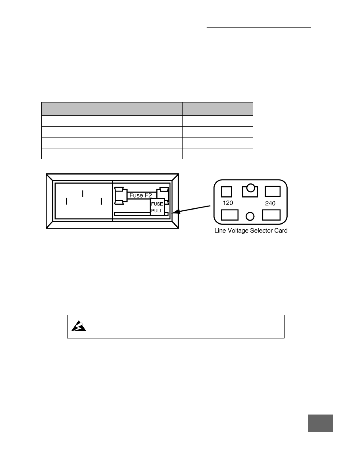
2.4.1 Line Voltage Selection
Verify that the line voltage selector card displays the line voltage value of the available local AC line
voltage. If the card does not display the correct line voltage value as shown in Table 2-1, perform
the following procedure and refer to Figure 2-1.
Table 2-1 Selector Card Line Voltage Settings and Fuse Selection
Line Voltage Setting (VAC) Setting Selector Card Fuse F2 Type
90-105 100 1.25A SB
105-130 120 1.25A SB
200-230 220 .60A SB
230-260 240 .60A SB
Figure 2-1 Line Voltage Selector on the rear of the 330 VGC
1. On the rear panel (lower right), slide the cover over fuse F2 to the left.
2. Remove fuse F2 by pulling the fuse extractor tab FUSE PULL outward and to the left. Leave the
extractor tab in the full-left position.
3. Use a pointed tool or small wire hook to extract the line selector card from its holder and pull
the card straight out.
4. Reinsert the card so that the correct line voltage as shown in Figure 2-1 is readable from the
rear of the VGC.
.
Operation of the Series 330 Vacuum Gauge Controller with the line voltage
selector card improperly set can cause damage to the Controller and injury to
personnel.
5. Verify that fuse F2 is the correct value as shown in Table 2-1. Position fuse extractor tab FUSE
PULL to the right-hand position and install fuse F2 in fuse holder.
6. Slide the cover to the right over fuse F2.
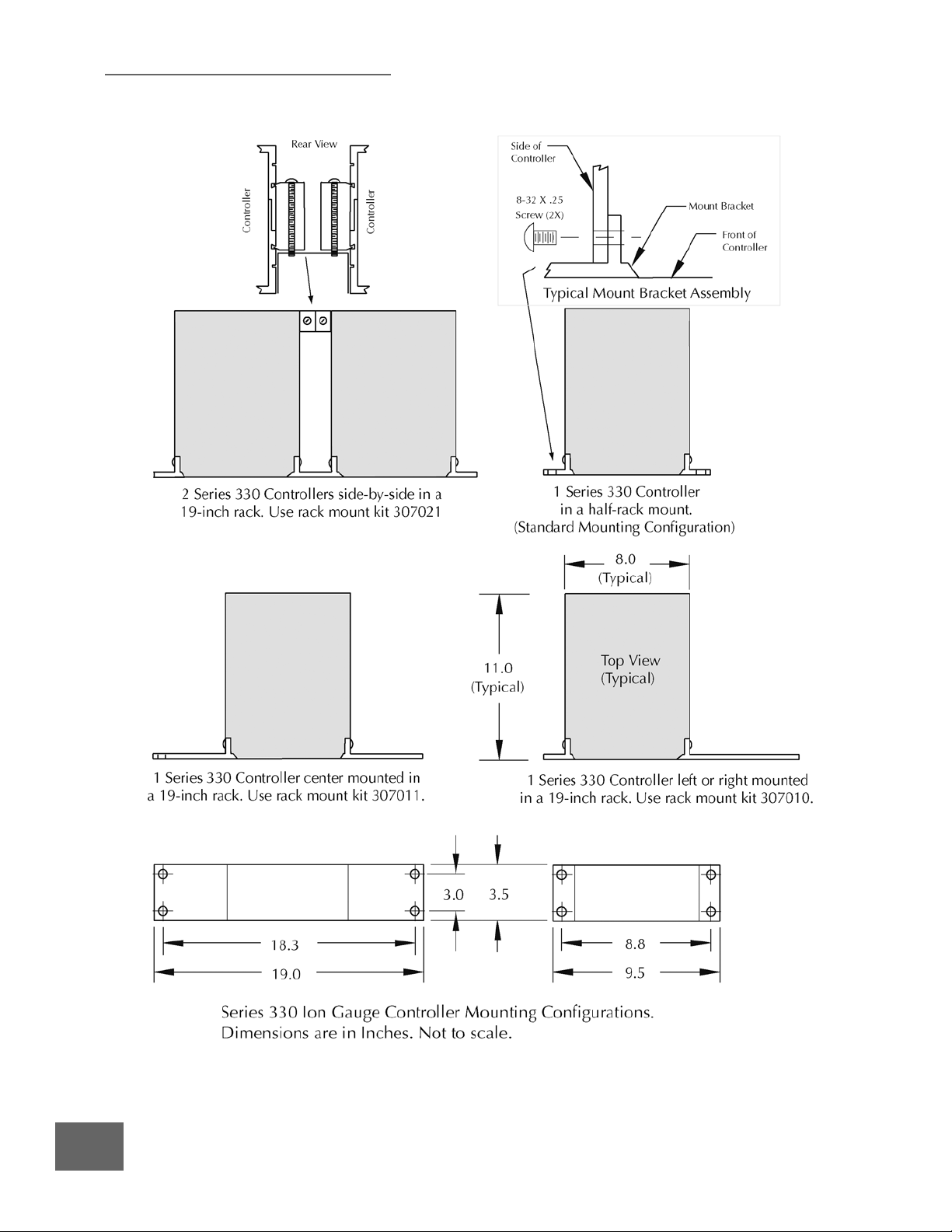
2.4.2 Mounting Configurations
Figure 2-2 illustrates the various configurations available for mounting the Series 330 Vacuum
Gauge Controller.
NOTE: The 330 controller should be mounted in a location with free air flow
and ambient temperature less than 40
o
C.
Series 330 Vacuum Gauge Controller
Instruction Manual - 330004 - Rev. 02
17
2 Installation
Figure 2-2 330 VGC Mounting Configurations
18
Series 330 Vacuum Gauge Controller
Instruction Manual - 330004 - Rev. 02

2 Installation
2.5 Ionization Gauge Types and Installation
The 330 VGC operates a Bayard-Alpert type or equivalent ionization gauge. It is ideally suited for a
nude ionization gauge such as the Granville-Phillips 274022 or 274023 which have an X-ray limit
in the low 10
pressures they provide longer operating life and greater burnout resistance.
When installing an ion gauge, note that if it is placed near the pump, the pressure in the gauge may
be considerably lower than in the rest of the system. If placed near a gas inlet or source of
contamination, the pressure in the gauge may be higher.
If an unshielded gauge is placed near an electron beam evaporation source or used in a sputtering
system, spurious electrons or ions may disturb the measurement. Screens or other shielding should
be placed between the gauge and the system if spurious charged particles or severe electromagnetic
interference is present. Consideration should also be given to electrostatic shielding of glass
tubulated gauges when measuring pressures near their x-ray limits.
Brooks Automation, Inc./Granville-Phillips offers 3 cable types for ion gauges. One has a standard
connector for the series 274 tubulated gauges; one has a standard connector for series 274 nude
gauges; and one has individual pin sockets for use with nonstandard pin configurations as well as
Granville-Phillips nude gauges.
-11
Torr range. Coated Iridium filament type gauges are recommended since at higher
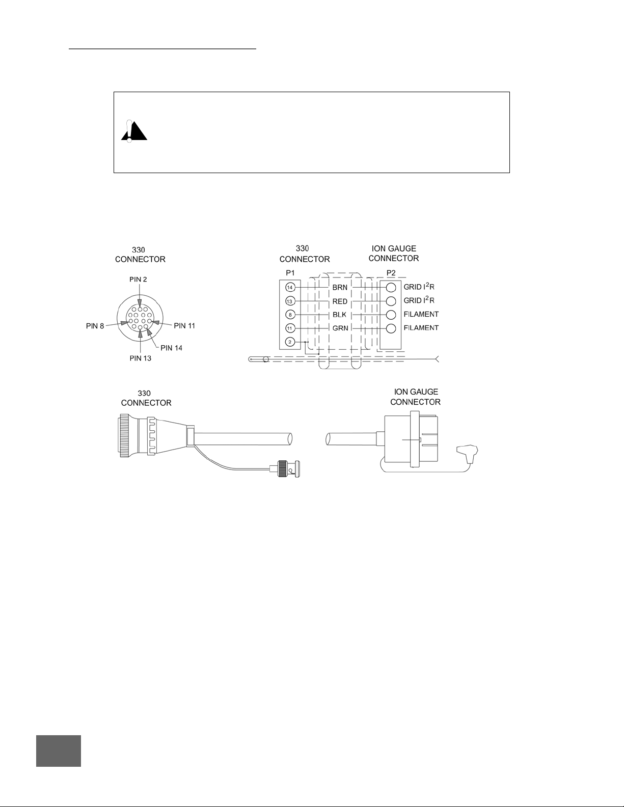
Figure 2-3 shows typical gauge base configurations using the cables listed above and shown in
Figure 2-4, 2-5, and 2-6.
NOTE: To use the second filament of a dual
filament gauge, the cable connector at the
gauge is removed and rotated 180
reinstalled.
o
, then
Figure 2-3 Standard Gauge Base Configuration
Series 330 Vacuum Gauge Controller
Instruction Manual - 330004 - Rev. 02
19
2 Installation
Do not attach cables to glass gauge pins while the gauge is under vacuum.
Accidental bending of the pins may cause the glass to break and implode.
Cables, once installed, should be secured to the system to provide strain relief
for gauge tube pins.
Ionization gauges are safe for use only if all exposed conductors on the gauge
and on controller and on vacuum system are grounded.
2.5.1 Ion Gauge Cables
Figure 2-4 Ion Gauge Cable for Granville-Phillips Glass Gauges
20
Series 330 Vacuum Gauge Controller
Instruction Manual - 330004 - Rev. 02
2 Installation
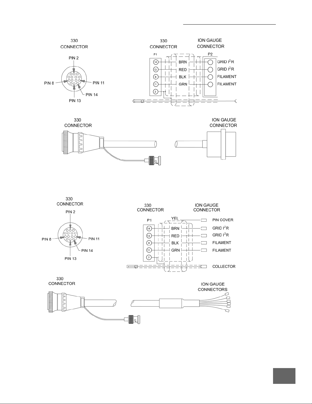
Figure 2-5 Ion Gauge Cable for Granville-Phillips Nude Gauges
Figure 2-6 Ion Gauge Cable for Granville-Phillips Nude Gauges
Series 330 Vacuum Gauge Controller
Instruction Manual - 330004 - Rev. 02
21
2 Installation
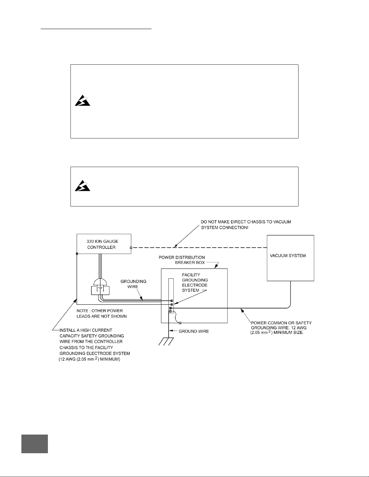
2.6 System Grounding Procedure
Improper grounding can cause product damage or personal injury.
• Follow ground network requirements for the facility.
• Maintain all exposed conductors at earth ground.
• Connect the power cord to a properly grounded outlet.
• Make sure the vacuum port to which the gauge is mounted is properly
grounded.
• Connect the gauge envelope to a facility ground. If necessary, use a ground lug
on the flange bolt or a hose clamp connected to the gauge/component.
High voltage can couple through a gas to the internal electrodes of a gauge. Do not touch the
exposed pins on any gauge installed on a vacuum system where high voltage is present.
Touching the pins on the gauge in a high−voltage environment can cause an
electrical discharge through a gas or plasma, resulting in property damage or
personal injury due to electrical shock.
Vent the vacuum chamber to atmospheric pressure and shut OFF power to the
controller before you touch the pins on the gauge.
Figure 2-7 System Grounding Diagram
22
Series 330 Vacuum Gauge Controller
Instruction Manual - 330004 - Rev. 02
2 Installation
The placement of a second ground wire (dashed line in Figure 2−7) between the
vacuum chamber and the 330 Vacuum Gauge Controller chassis is NOT safe −
large currents could flow through it.
After each maintenance/service procedure and before operating the controller
and vacuum system, make sure that your vacuum system and controller are
grounded as shown in Figure 2−7.
FAILURE TO DO SO COULD BE FATAL.
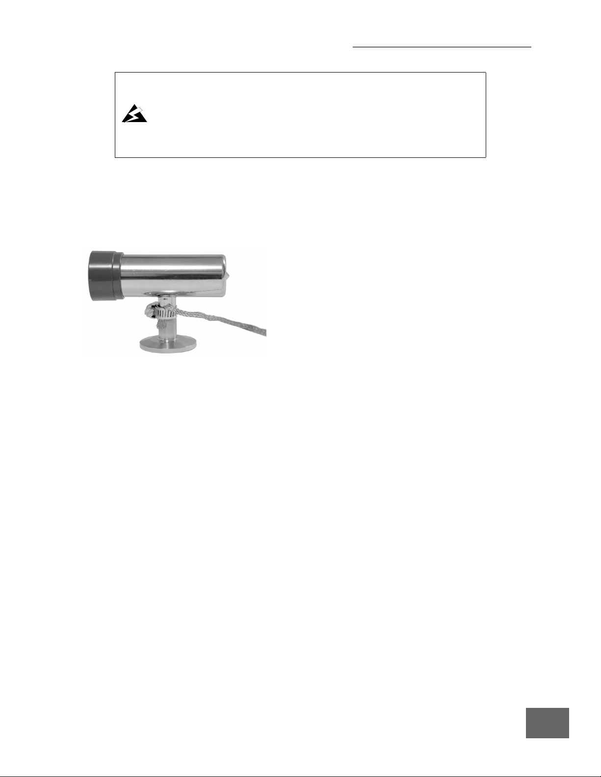
When high voltages are used within the vacuum system and the gauge envelope is not reliably
grounded through its vacuum connection, either a separate ground wire must be added, or the
envelope must be shielded to positively prevent human contact. The gauge envelope may be
grounded by using a metal hose clamp on the gauge connected by a #12 awg copper wire to the
grounded vacuum chamber. See Figure 2-8.
Figure 2-8 Grounding a Convectron Gauge
1. Connect a heavy duty ground wire #12 AWG or larger from the ground lug on the back of the
Controller to your facility grounding electrode system. This will provide an earth ground for
the Controller in the event the interconnect cables are not in place. Do not connect the ground
lug to the vacuum system or other component. Connect it directly to the facility grounding
system such as a grounded outlet box or a grounded copper water supply pipe. Do not rely on
small metal water lines to ground a component. Later on someone may replace the metal
tubing with plastic tubing thus unwittingly causing a potentially dangerous situation.
2. Provide a connection to ground for other instruments with electrodes in the vacuum system
possibly exposed to high voltage electrical discharges.
3. Provide a connection to ground for each ungrounded metal component in, on or around the
vacuum system, including the gauge envelopes, which personnel may touch and which can
potentially be exposed to high voltage electrical discharges within the vacuum system. For
example, a metal bell jar resting on an organic O-ring must be connected to ground if a
Micro-Ion gauge is to be used or if other high voltage sources are present in the vacuum
system.
Series 330 Vacuum Gauge Controller
Instruction Manual - 330004 - Rev. 02
23
 Loading...