

Granville-Phillips Micro-Ion DeviceNet 390 Series, Micro-Ion DeviceNet 390611 Series, Micro-Ion DeviceNet 390610 Series Instruction Manual

Series 390
Granville-Phillips® Series 390 Micro-Ion® ATM
Four-Sensor Combination Vacum Gauge Module
™
with DeviceNet
and Analog Output
and RS-485 Interface,
Instruction Manual
Instruction manual part number 390002
Revision E - August 2013


Series 390
Granville-Phillips® Series 390 Micro-Ion® ATM
Four-Sensor Combination Vacum Gauge Module
™
with DeviceNet
and Analog Output
This Instruction Manual is for use with all Granville-Phillips Series
390 Micro-Ion ATM Modules with DeviceNet and RS-485 Interface,
and Analog Output. A list of applicable catalog numbers is provided
on the following page.
These products are RoHS compliant.
Customer Service/Support
For customer service within USA, 8 AM to 5 PM
Mountain Time Zone, weekdays excluding holidays:
Granville-Phillips
6450 Dry Creek Parkway
Longmont, CO 80503 USA
Phone: +1-800-776-6543
Phone: +1-303-652-4400
FAX: +1-303-652-2844
Email: co-csr@brooks.com
Brooks Automation, Inc.
15 Elizabeth Drive
Chelmsford, MA 01824 USA
Phone: +1-978-262-2400
For customer service, 24 hours per day, 7 days per week,
every day of the year including holidays within the USA:
Phone: +1-800-367-4887
www.brooks.com
and RS-485 Interface,
Instruction Manual
© 2006-2013 Brooks Automation, Inc. All rights reserved.
Granville-Phillips
Brooks Automation, Inc. All other trademarks and registered trademarks are the
properties of their respective owners.
®
, Micro-Ion®, and Conductron® are registered trademarks of

Granville-Phillips® Series 390 Micro-Ion® ATM
Four-Sensor Combination Vacum Gauge
with DeviceNet
Catalog numbers for Series 390 Micro-Ion ATM Modules
Power supply and cable are not included.
DeviceNet interface - no display: 390610 - # - # # - #
DeviceNet interface - with digital display: 390611 - # - # # - #
Setpoints:
None 0
Two 2
Three 3
Ion Gauge Filaments:
Yttria-coated iridium Y
Tungsten T
Flange/Fitting:
NW16KF D
NW25KF E
NW40KF K
1.33 inch (NW16CF) Conflat-type F
2.75 inch (NW35CF) Conflat-type G
1/2 inch VCR-type male H
™ and RS-485 Interface, and Analog Output
Measurement Units:
Tor r T
mbar M
Pascal P

Table of Contents
Table of Contents
Chapter 1 Before You Begin . . . . . . . . . . . . . . . . . . . . . . . . . . . . . . . . . . . . 9
1.1 About these instructions . . . . . . . . . . . . . . . . . . . . . . . . . . . 9
1.2 Caution and warning statements . . . . . . . . . . . . . . . . . . . . . 9
1.3 System Grounding . . . . . . . . . . . . . . . . . . . . . . . . . . . . . . . 10
1.4 Implosion / Explosion . . . . . . . . . . . . . . . . . . . . . . . . . . . . . 10
1.5 Operation . . . . . . . . . . . . . . . . . . . . . . . . . . . . . . . . . . . . . . 11
1.6 Reading and following instructions . . . . . . . . . . . . . . . . . . . 11
1.7 Definitions of terms . . . . . . . . . . . . . . . . . . . . . . . . . . . . . . . 12
1.8 Customer service . . . . . . . . . . . . . . . . . . . . . . . . . . . . . . . . 14
Chapter 2 Installation . . . . . . . . . . . . . . . . . . . . . . . . . . . . . . . . . . . . . . . . . . 15
2.1 Module components . . . . . . . . . . . . . . . . . . . . . . . . . . . . . . 15
2.2 Pressure relief devices . . . . . . . . . . . . . . . . . . . . . . . . . . . . . 15
2.3 Installation procedure . . . . . . . . . . . . . . . . . . . . . . . . . . . . . 16
Step 1 Locate the module . . . . . . . . . . . . . . . . . . . . . . . . 16
Step 2 Attach the module to the vacuum chamber . . . . . 18
VCR type fitting . . . . . . . . . . . . . . . . . . . . . . . . . . . . . . . . . . 18
KF flange . . . . . . . . . . . . . . . . . . . . . . . . . . . . . . . . . . . . . . . 18
ConFlat flange . . . . . . . . . . . . . . . . . . . . . . . . . . . . . . . . . . . 18
Step 3 Assemble and connect wiring . . . . . . . . . . . . . . . . 19
Connecting cable . . . . . . . . . . . . . . . . . . . . . . . . . . . . . . . . 19
CE Mark compliance . . . . . . . . . . . . . . . . . . . . . . . . . . . . . . 20
Module power supply . . . . . . . . . . . . . . . . . . . . . . . . . . . . . 20
Gauge OFF/degas wiring . . . . . . . . . . . . . . . . . . . . . . . . . . . 21
Relay, analog output, and RS-485 output wiring . . . . . . . . . 21
DeviceNet wiring . . . . . . . . . . . . . . . . . . . . . . . . . . . . . . . . 22
Grounding . . . . . . . . . . . . . . . . . . . . . . . . . . . . . . . . . . . . . 22
Step 4 Calibrate module at atmospheric pressure . . . . . . 24
2.4 Eliminating radio frequency interference . . . . . . . . . . . . . . . 24
Chapter 3 Operation Overview . . . . . . . . . . . . . . . . . . . . . . . . . . . . . . . . . . 25
3.1 Interfaces, outputs, and relays . . . . . . . . . . . . . . . . . . . . . . . 25
3.2 Analog operation . . . . . . . . . . . . . . . . . . . . . . . . . . . . . . . . 25
3.3 DeviceNet operation . . . . . . . . . . . . . . . . . . . . . . . . . . . . . . 25
3.4 RS-485 operation . . . . . . . . . . . . . . . . . . . . . . . . . . . . . . . . 27
3.5 Automatic filament selection . . . . . . . . . . . . . . . . . . . . . . . . 28
Chapter 4 Analog Operation . . . . . . . . . . . . . . . . . . . . . . . . . . . . . . . . . . . . . 29
4.1 Output functions . . . . . . . . . . . . . . . . . . . . . . . . . . . . . . . . . 29
4.2 Preparing to operate the module . . . . . . . . . . . . . . . . . . . . . 29
Micro-Ion®ATM Module Instruction Manual - 390002 - Rev. E 5

Table of Contents
4.3 Operational tasks . . . . . . . . . . . . . . . . . . . . . . . . . . . . . . . . 29
4.4 LED status indicator . . . . . . . . . . . . . . . . . . . . . . . . . . . . . . 30
4.5 Reading pressure . . . . . . . . . . . . . . . . . . . . . . . . . . . . . . . . . 31
4.6 Micro-Ion gauge OFF . . . . . . . . . . . . . . . . . . . . . . . . . . . . . 32
4.7 Micro-Ion gauge degas . . . . . . . . . . . . . . . . . . . . . . . . . . . . 33
4.8 Calibration . . . . . . . . . . . . . . . . . . . . . . . . . . . . . . . . . . . . . 34
Atmospheric pressure calibration . . . . . . . . . . . . . . . . . . . . 35
Vacuum pressure calibration . . . . . . . . . . . . . . . . . . . . . . . . 35
Chapter 5 DeviceNet Operation . . . . . . . . . . . . . . . . . . . . . . . . . . . . . . . . . . 37
5.1 Pressure output and relay functions . . . . . . . . . . . . . . . . . . . 37
5.2 Preparing to operate the module . . . . . . . . . . . . . . . . . . . . . 37
5.3 Performance with DeviceNet protocol . . . . . . . . . . . . . . . . 38
5.4 DeviceNet protocol for the Micro-Ion ATM module . . . . . . 39
5.5 Operational tasks . . . . . . . . . . . . . . . . . . . . . . . . . . . . . . . . 39
5.6 DeviceNet switches and indicators . . . . . . . . . . . . . . . . . . . 40
Address switches . . . . . . . . . . . . . . . . . . . . . . . . . . . . . . . . . 40
Rate switch . . . . . . . . . . . . . . . . . . . . . . . . . . . . . . . . . . . . . 41
5.7 Status LEDs . . . . . . . . . . . . . . . . . . . . . . . . . . . . . . . . . . . . . 41
5.8 DeviceNet communication configuration . . . . . . . . . . . . . . 43
5.9 Pressure units and values . . . . . . . . . . . . . . . . . . . . . . . . . . 47
Set or get pressure unit . . . . . . . . . . . . . . . . . . . . . . . . . . . . 47
Data conversion . . . . . . . . . . . . . . . . . . . . . . . . . . . . . . . . . 47
Get vacuum pressure or differential pressure . . . . . . . . . . . . 48
5.10 Get temperature . . . . . . . . . . . . . . . . . . . . . . . . . . . . . . . . . 51
5.11 Process control relays . . . . . . . . . . . . . . . . . . . . . . . . . . . . . 51
Get relay trip points . . . . . . . . . . . . . . . . . . . . . . . . . . . . . . 55
Get enable/disable status of relays . . . . . . . . . . . . . . . . . . . 55
Get activation or deactivation status of relays . . . . . . . . . . . 56
Get relay hysteresis . . . . . . . . . . . . . . . . . . . . . . . . . . . . . . . 57
Get relay assignments . . . . . . . . . . . . . . . . . . . . . . . . . . . . . 57
5.12 Micro-Ion gauge controls . . . . . . . . . . . . . . . . . . . . . . . . . . 58
Turn Micro-Ion gauge ON or OFF . . . . . . . . . . . . . . . . . . . 58
Get Micro-Ion gauge ON/OFF status . . . . . . . . . . . . . . . . . . 59
Set or get Micro-Ion gauge delay time . . . . . . . . . . . . . . . . . 59
Set or get filament mode . . . . . . . . . . . . . . . . . . . . . . . . . . . 60
Get active filament . . . . . . . . . . . . . . . . . . . . . . . . . . . . . . . 61
Initiate or terminate Micro-Ion gauge degas . . . . . . . . . . . . 62
Get Micro-Ion gauge degas ON/OFF state . . . . . . . . . . . . . . 63
Set or get Micro-Ion gauge emission current . . . . . . . . . . . . 63
5.13 Calibrate module at atmospheric pressure . . . . . . . . . . . . . . 65
5.14 Calibrate module at vacuum pressure . . . . . . . . . . . . . . . . . 65
5.15 Reset module to power-up state . . . . . . . . . . . . . . . . . . . . . 66
5.16 Get firmware version . . . . . . . . . . . . . . . . . . . . . . . . . . . . . 66
5.17 Get software and hardware revision levels . . . . . . . . . . . . . 66
6 Micro-Ion
®
ATM Module Instruction Manual - 390002 - Rev. E

Table of Contents
5.18 Factory defaults . . . . . . . . . . . . . . . . . . . . . . . . . . . . . . . . . . 67
5.19 DeviceNet error codes . . . . . . . . . . . . . . . . . . . . . . . . . . . . 68
Using polled I/O . . . . . . . . . . . . . . . . . . . . . . . . . . . . . . . . . 68
Using explicit messages . . . . . . . . . . . . . . . . . . . . . . . . . . . 68
Chapter 6 RS-485 Operation . . . . . . . . . . . . . . . . . . . . . . . . . . . . . . . . . . . . 73
6.1 Pressure output and relay functions . . . . . . . . . . . . . . . . . . . 73
6.2 Preparing to operate the module . . . . . . . . . . . . . . . . . . . . . 73
6.3 RS-485 physical layer . . . . . . . . . . . . . . . . . . . . . . . . . . . . . 74
6.4 Operational tasks . . . . . . . . . . . . . . . . . . . . . . . . . . . . . . . . 75
6.5 Error responses . . . . . . . . . . . . . . . . . . . . . . . . . . . . . . . . . . 75
6.6 Data timing and response . . . . . . . . . . . . . . . . . . . . . . . . . . 76
6.7 RS-485 commands . . . . . . . . . . . . . . . . . . . . . . . . . . . . . . . 77
Command structure . . . . . . . . . . . . . . . . . . . . . . . . . . . . . . 77
Symbols used in this manual . . . . . . . . . . . . . . . . . . . . . . . . 77
6.8 RS-485 command set . . . . . . . . . . . . . . . . . . . . . . . . . . . . . 78
TLU Toggling locked functions . . . . . . . . . . . . . . . . . . . 80
UNL Unlock interface functions . . . . . . . . . . . . . . . . . . 80
SA Set address offset . . . . . . . . . . . . . . . . . . . . . . . . . 81
SB Set baud rate . . . . . . . . . . . . . . . . . . . . . . . . . . . . 82
yuiop Restore RS-485 communication defaults . . . . . . . . 82
SU Set pressure unit . . . . . . . . . . . . . . . . . . . . . . . . . . 82
RU Read pressure unit . . . . . . . . . . . . . . . . . . . . . . . . 82
SD Set pressure indication for optional display . . . . . . 82
RD Read vacuum pressure . . . . . . . . . . . . . . . . . . . . . 83
RDD Read differential pressure . . . . . . . . . . . . . . . . . . . 83
PC Process control relay trip points . . . . . . . . . . . . . . 84
PCG Set trip point relay assignments . . . . . . . . . . . . . . . 87
PCE Set or read disable/enable state of relays . . . . . . . . 87
RPCS Read trip point relay status . . . . . . . . . . . . . . . . . . 88
IG Turn Micro-Ion gauge ON or OFF . . . . . . . . . . . . 88
IGS Read Micro-Ion gauge ON/OFF status . . . . . . . . . 88
IGM Set or read pressure indication when
Micro-Ion gauge is OFF . . . . . . . . . . . . . . . . . . . . 89
IOD Set or read Micro-Ion gauge delay ON/OFF state . 90
IDT Set or read Micro-Ion gauge delay time . . . . . . . . 91
SF Set Micro-Ion gauge filament mode . . . . . . . . . . . 92
RF Read Micro-Ion gauge filament status . . . . . . . . . . 96
DG Degas Micro-Ion gauge . . . . . . . . . . . . . . . . . . . . 96
DGS Read Micro-Ion gauge degas status . . . . . . . . . . . . 96
DGT Set or read Micro-Ion gauge degas time . . . . . . . . 97
SER Set emission current switch point . . . . . . . . . . . . . 97
RE Read Micro-Ion gauge emission current . . . . . . . . 99
TS Calibrate module at atmospheric pressure . . . . . . 99
TZ Calibrate module at vacuum pressure . . . . . . . . . . 100
Micro-Ion®ATM Module Instruction Manual - 390002 - Rev. E 7

Table of Contents
ATM Set or read atmospheric pressure output . . . . . . . . 101
RS Read module status RS-485 strings . . . . . . . . . . . . 101
RSX Read module status hexadecimal bits . . . . . . . . . . 103
RST Reset module to power-up state . . . . . . . . . . . . . . 105
FAC Reset values to factory defaults . . . . . . . . . . . . . . . 106
VER Read firmware version . . . . . . . . . . . . . . . . . . . . . 106
Chapter 7 Optional Display . . . . . . . . . . . . . . . . . . . . . . . . . . . . . . . . . . . . . 107
7.1 Display capabilities . . . . . . . . . . . . . . . . . . . . . . . . . . . . . . . 107
Vacuum pressure display . . . . . . . . . . . . . . . . . . . . . . . . . . 107
Differential pressure display . . . . . . . . . . . . . . . . . . . . . . . . 107
7.2 Display resolution . . . . . . . . . . . . . . . . . . . . . . . . . . . . . . . . 108
7.3 Error conditions . . . . . . . . . . . . . . . . . . . . . . . . . . . . . . . . . 108
Chapter 8 Maintenance . . . . . . . . . . . . . . . . . . . . . . . . . . . . . . . . . . . . . . . . . 111
8.1 Customer service . . . . . . . . . . . . . . . . . . . . . . . . . . . . . . . . 111
Damage requiring service . . . . . . . . . . . . . . . . . . . . . . . . . . 111
8.2 Troubleshooting . . . . . . . . . . . . . . . . . . . . . . . . . . . . . . . . . 111
Precautions . . . . . . . . . . . . . . . . . . . . . . . . . . . . . . . . . . . . . 112
Symptoms, causes, and solutions . . . . . . . . . . . . . . . . . . . . 112
8.3 RS-485 error responses . . . . . . . . . . . . . . . . . . . . . . . . . . . . 114
8.4 RS-485 status strings and hexadecimal bits . . . . . . . . . . . . . 115
8.5 DeviceNet error codes . . . . . . . . . . . . . . . . . . . . . . . . . . . . 115
Using polled I/O . . . . . . . . . . . . . . . . . . . . . . . . . . . . . . . . . 115
Using explicit messages . . . . . . . . . . . . . . . . . . . . . . . . . . . 115
8.6 Overpressure shutdown . . . . . . . . . . . . . . . . . . . . . . . . . . . 116
8.7 Micro-Ion gauge continuity test . . . . . . . . . . . . . . . . . . . . . . 116
8.8 Replacing the gauge assembly . . . . . . . . . . . . . . . . . . . . . . 118
8.9 Returning a Micro-Ion module for service . . . . . . . . . . . . . . 119
Appendix A Specifications & Compliance . . . . . . . . . . . . . . . . . . . . . . . . . . 121
Appendix B Messaging Summary . . . . . . . . . . . . . . . . . . . . . . . . . . . . . . . . . 129
Appendix C Theory of Operation . . . . . . . . . . . . . . . . . . . . . . . . . . . . . . . . . . 143
Index . . . . . . . . . . . . . . . . . . . . . . . . . . . . . . . . . . . . . . . . . . . . . . . . . . . . . . . . . . . . . . . . . . . . . . . . . . . . . 147
8 Micro-Ion
®
ATM Module Instruction Manual - 390002 - Rev. E
Chapter 1 Before You Begin
CAUTION
Before You Begin
Before You Begin Installation Operation Overview Analog Operation
1.1 About these instructions These instructions explain how to install, operate, and maintain the
Granville-Phillips
The module has a DeviceNet interface, an RS-485 interface, and one analog
output. The module may have no trip point relays, two trip point relays, or
three trip point relays.
• This chapter explains caution and warning statements, which must be
adhered to at all times; explains your responsibility for reading and
following all instructions; defines the terms that are used throughout this
instruction manual; and explains how to contact customer service.
• Chapter 2 explains how to install the module.
• Chapter 3 is an operational overview of the module.
• Chapter 4 explains analog output operation. The analog output does not
operate independently but must operate with the DeviceNet or RS-485
interface.
• Chapter 5 explains DeviceNet interface operation.
• Chapter 6 explains RS-485 interface operation.
• Chapter 7 explains how to use the optional display.
• Chapter 8 explains troubleshooting; Micro-Ion gauge testing, removal
and replacement; and module return procedures.
• Appendix A provides specifications for the module.
• Appendix B summarizes DeviceNet polled I/O and explicit messages.
• Appendix C explains how the Micro-Ion gauge, Conductron
sensor, atmospheric pressure diaphragm sensor, and vacuum pressure
diaphragm sensor measure pressure.
®
Micro-Ion® ATM vacuum gauge module.
®
heat-loss
1.2 Caution and warning statements
This manual contains caution and warning statements with which you must
comply with to prevent inaccurate measurement, property damage, or
personal injury.
Caution statements alert you to hazards or unsafe
practices that could result in inaccurate measurement,
minor personal injury or property damage.
Each caution statement explains what you must do to prevent or
avoid the potential result of the specified hazard or unsafe
practice.
Micro-Ion®ATM Module Instruction Manual - 390002 - Rev. E 9

Chapter 1
WARNING
Warning statements alert you to hazards or unsafe
practices that could result in severe property damage or
personal injury due to electrical shock, fire, or explosion.
Each warning statement explains what you must do to prevent
or avoid the potential result of the specified hazard or unsafe
practice.
Caution and warning statements comply with American Institute of
Standards Z535.1-2002 through Z535.5-2002, which set forth voluntary
practices regarding the content and appearance of safety signs, symbols,
and labels.
Each caution or warning statement explains:
a. The specific hazard that you must prevent or unsafe practice that you
must avoid,
b. The potential result of your failure to prevent the specified hazard or
avoid the unsafe practice, and
c. What you must do to prevent the specified hazardous result.
1.3 System Grounding Grounding, though simple, is very important! Be certain that ground
circuits are correctly used on your ion gauge power supplies, gauges, and
vacuum chambers, regardless of their manufacturer. Safe operation of
vacuum equipment, including the Series 390 ATM Module, requires
grounding of all exposed conductors of the gauges, the controller and the
vacuum system. LETHAL VOLTAGES may be established under some
operating conditions unless correct grounding is provided.
Ion producing equipment, such as ionization gauges, mass spectrometers,
sputtering systems, etc., from many manufacturers may, under some
conditions, provide sufficient electrical conduction via a plasma to couple
a high voltage electrode potential to the vacuum chamber. If exposed
conductive parts of the gauge, controller, and chamber are not properly
grounded, they may attain a potential near that of the high voltage electrode
during this coupling. Potential fatal electrical shock could then occur
because of the high voltage between these exposed conductors and ground.
1.4 Implosion / Explosion Danger of injury to personnel and damage to equipment exists on all
vacuum systems that incorporate gas sources or involve processes capable
of pressuring the system above the limits it can safely withstand.
For example, danger of explosion in a vacuum system exists during
backfilling from pressurized gas cylinders because many vacuum devices
such as ionization gauge tubes, glass windows, glass belljars, etc., are not
designed to be pressurized.
10 Micro-Ion
®
ATM Module Instruction Manual - 390002 - Rev. E

Before You Begin
Install suitable devices that will limit the pressure from external gas sources
to the level that the vacuum system can safely withstand. In addition, install
suitable pressure relief valves or rupture disks that will release pressure at a
level considerably below that pressure which the system can safely
withstand.
Suppliers of pressure relief valves and pressure relief disks are listed in
Thomas Register under "Valves, Relief", and "Discs, Rupture".
Confirm that these safety devices are properly installed before installing the
Series 390 ATM Module. In addition, check that (1) the proper gas cylinders
are installed, (2) gas cylinder valve positions are correct on manual systems,
and (3) the automation is correct on automated systems.
1.5 Operation It is the installer's responsibility to ensure that the automatic signals
provided by the process control module are always used in a safe manner.
Carefully check manual operation of the system and the setpoint
programming before switching to automatic operation. Where an
equipment malfunction could cause a hazardous situation, always provide
for fail-safe operation. As an example, in an automatic backfill operation
where a malfunction might cause high internal pressures, provide an
appropriate pressure relief device.
Before You Begin Installation Operation Overview Analog Operation
1.6 Reading and following instructions
You must comply with all instructions while you are installing, operating,
or maintaining the module. Failure to comply with the instructions violates
standards of design, manufacture, and intended use of the module.
Granville-Phillips and Brooks Automation disclaim all liability for the
customer's failure to comply with the instructions.
• Read instructions – Read all instructions before installing or operating the
product.
• Follow instructions – Follow all installation, operating and maintenance
instructions.
• Retain instructions – Retain the instructions for future reference.
• Heed warnings and cautions – Adhere to all warnings and caution
statements on the product and in these instructions.
• Parts and accessories – Install only those replacement parts and
accessories that are recommended by Granville-Phillips. Substitution of
parts is hazardous.
Micro-Ion®ATM Module Instruction Manual - 390002 - Rev. E 11

Chapter 1
1.7 Definitions of terms
Table 1-1 lists terms used throughout this manual in reference to the
Micro-Ion ATM vacuum gauge module.
Table 1-2 lists terms describing DeviceNet protocol.
Table 1-3 lists terms describing DeviceNet data types.
Table 1-1 Terms describing Micro-Ion ATM module and components
Term Description
Module The entire Micro-Ion ATM product, which includes the housing, gauge assembly,
Gauge assembly A removable assembly that contains a hot filament Micro-Ion gauge
Electronics assembly An assembly that contains the electronic circuitry, signal processing
Micro-Ion
Conductron
®
gauge The Bayard-Alpert type ionization gauge, which indicates pressure by producing
®
sensor The heat-loss sensor, which measures pressure as a function of heat loss from the
Vacuum pressure diaphragm sensor A Piezo resistive diaphragm sensor that measures vacuum pressure. Vacuum
Atmospheric pressure diaphragm
sensor
Vacuum pressure The pressure of the process gas inside the vacuum chamber, measured by the
Atmospheric pressure The ambient air pressure of the atmosphere outside the module, measured by the
Differential pressure The difference between atmospheric pressure and vacuum pressure. Differential
and electronics assembly.
(Bayard-Alpert type ionization gauge), a Conductron heat-loss sensor, a vacuum
pressure diaphragm sensor, and the vacuum chamber connection.
microcircuitry, and atmospheric pressure diaphragm sensor.
a current that is proportional to gas density.
gold-plated tungsten sensing wire.
pressure is compared to atmospheric pressure to determine the differential
between atmospheric and vacuum pressures.
A Piezo resistive diaphragm sensor that measures atmospheric pressure.
Atmospheric pressure is compared to vacuum pressure to determine the
differential between atmospheric and vacuum pressures.
Micro-Ion gauge, Conductron sensor, and vacuum pressure diaphragm sensor.
atmospheric pressure diaphragm sensor.
pressure zero is the pressure value at which vacuum pressure equals atmospheric
pressure.
12 Micro-Ion
®
ATM Module Instruction Manual - 390002 - Rev. E

Before You Begin
Table 1-2 Terms describing DeviceNet protocol
Term Description
Class Referred to in DeviceNet language as an “object”. The DeviceNet protocol is
divided into various objects that describe behaviors, attributes, or information.
For example, class 1 is the identity object that includes information about the
identity of the product, such as the vendor identification, product type, product
ID, serial number, and firmware revisions.
Instance Within a class there may be multiple instances. Within the Micro-Ion ATM
module there are four possible I/O instances (1–4). For example, the format for
polled I/O data is instance 2 in class 5.
Attribute Data that can be read from the device or written to the DeviceNet network.
Attributes exist for each instance within a class. For example, the serial number is
attribute 6, instance 1 in class 1 (the identity object).
Master data The messages sent from the network to the device to set conditions or values in
the device.
Device data The messages sent from the Micro-Ion ATM module to the network to
communicate values, attributes, or other information.
Data rate The rate at which data is transmitted (125, 250, or 500 kbaud, switch selectable).
Explicit messages Messages that are used for request/response communications enabling module
configuration and problem diagnosis. Explicit messages provide multi-purpose,
point-to-point communication paths between two modules or other devices.
Polled I/O messages Messages that are used for time-critical, control-oriented data. Polled I/O
messages provide a dedicated, special-purpose communication path between a
producing application (host) and one or more consuming applications (modules
or other devices).
Address The address of a device on the DeviceNet network.
Before You Begin Installation Operation Overview Analog Operation
Micro-Ion®ATM Module Instruction Manual - 390002 - Rev. E 13

Chapter 1
Table 1-3 Terms describing DeviceNet data types
Term Description
Data type The form of the data communicated from the Micro-Ion ATM module or another
node on the network. The module supports BOOL, BYTE, SSTRING, REAL, INT,
UINT, USINT, EPATH, and WORD data types.
BOOL data A single ON/OFF bit, where 1 = ON (true), 0 = OFF (false).
BYTE data An 8-bit string, from most significant to least significant bit.
STRUCT data A string of bits, each of which can be set to ON (true) = 1 or OFF (false) = 0.
SSTRING data A character string, one byte per character, with one byte length indicator.
REAL data A 32-bit floating point value in single precision IEEE 754 format.
INT data A 2-byte (16-bit) integer value from –32767 to +32767.
UINT data A 16-bit unsigned integer value from 0 to 65535.
USINT data An 8-bit unsigned integer value from 0 to 255.
EPATH DeviceNet path segments requiring abstract syntax encoding.
WORD data A 16-bit string.
1.8 Customer service
For customer service:
• Phone 1-303-652-4400 or 1-800-776-6543, 8 AM to 5 PM Mountain
Time Zone weekdays, excluding holidays within the USA.
• Phone 1-800-367-GUTS (1-800-367-4887) 24 hours per day, seven days
per week within the USA.
• Email co-csr@brooks.com
• For Global Customer Support, go to www.brooks.com and click on
Services to locate the Brooks Automation office nearest you.
14 Micro-Ion
®
ATM Module Instruction Manual - 390002 - Rev. E
Installation
WARNING
WARNING
CAUTION
Chapter 2 Installation
2.1 Module components The Micro-Ion ATM module contains a Micro-Ion gauge (Bayard-Alpert
type ionization gauge), a Conductron heat-loss sensor, an atmospheric
pressure diaphragm sensor, and a vacuum pressure diaphragm sensor.
Using the module to measure the pressure of flammable
or explosive gases can cause a fire or explosion resulting
in severe property damage or personal injury.
Do not use the module to measure the pressure of flammable or
explosive gases.
Exposing the module to moisture can cause fire or
electrical shock resulting in severe property damage or
personal injury.
To avoid exposing the module to moisture, install the module in
an indoor environment. Do not install the module in any
outdoor environment.
Before You Begin Installation Operation Overview Analog Operation
2.2 Pressure relief devices Before you install the module, you should install appropriate pressure relief
devices in the vacuum system.
Brooks Automation does not supply pressure relief valves or rupture disks.
Suppliers of pressure relief valves and rupture disks are listed in the Thomas
Register under “Valves, Relief” and “Discs, Rupture.”
Operating the module above 1000 Torr (1333 mbar, 133
kPa) true pressure could cause pressure measurement
error or product failure.
To avoid measurement error or product failure due to
overpressurization, install pressure relief valves or rupture
disks in the system if pressure substantially exceeds 1000 Torr
(1333 mbar, 133 kPa).
Micro-Ion®ATM Module Instruction Manual - 390002 - Rev. E 15

Chapter 2
2.3 Installation procedure
The module installation procedure includes the following steps:
1. Determine the location of the module on the vacuum chamber.
2. Attach the module’s flange / fitting to its mating fitting on the vacuum
chamber.
3. Assemble and connect the module wiring.
4. Calibrate the module at atmospheric pressure.
This chapter also explains what to do if radio frequency interference (RFI)
disrupts operation of RS-485 version of the module.
Step 1 Locate the module
To locate the module, refer to Figure 2-1 and follow the guidelines below.
• For greatest accuracy and repeatability, locate the module in a stable,
room-temperature environment. Ambient temperature should never
exceed 40 °C (104 °F) operating, non-condensing, or 85 °C (185 °F)
non-operating. Bakeout temperature with the electronics removed from
the module is 105 °C (221 °F).
• Locate the module away from internal and external heat sources and in
an area where ambient temperature remains reasonably constant.
• Do not locate the module near the pump, where gauge pressure might be
lower than system vacuum pressure.
• Do not locate the module near a gas inlet or other source of
contamination, where inflow of gas or particulates causes atmospheric
pressure to be higher than system atmosphere.
• Do not locate the module where it will be exposed to corrosive gases
such as mercury vapor or fluorine.
16 Micro-Ion
®
ATM Module Instruction Manual - 390002 - Rev. E
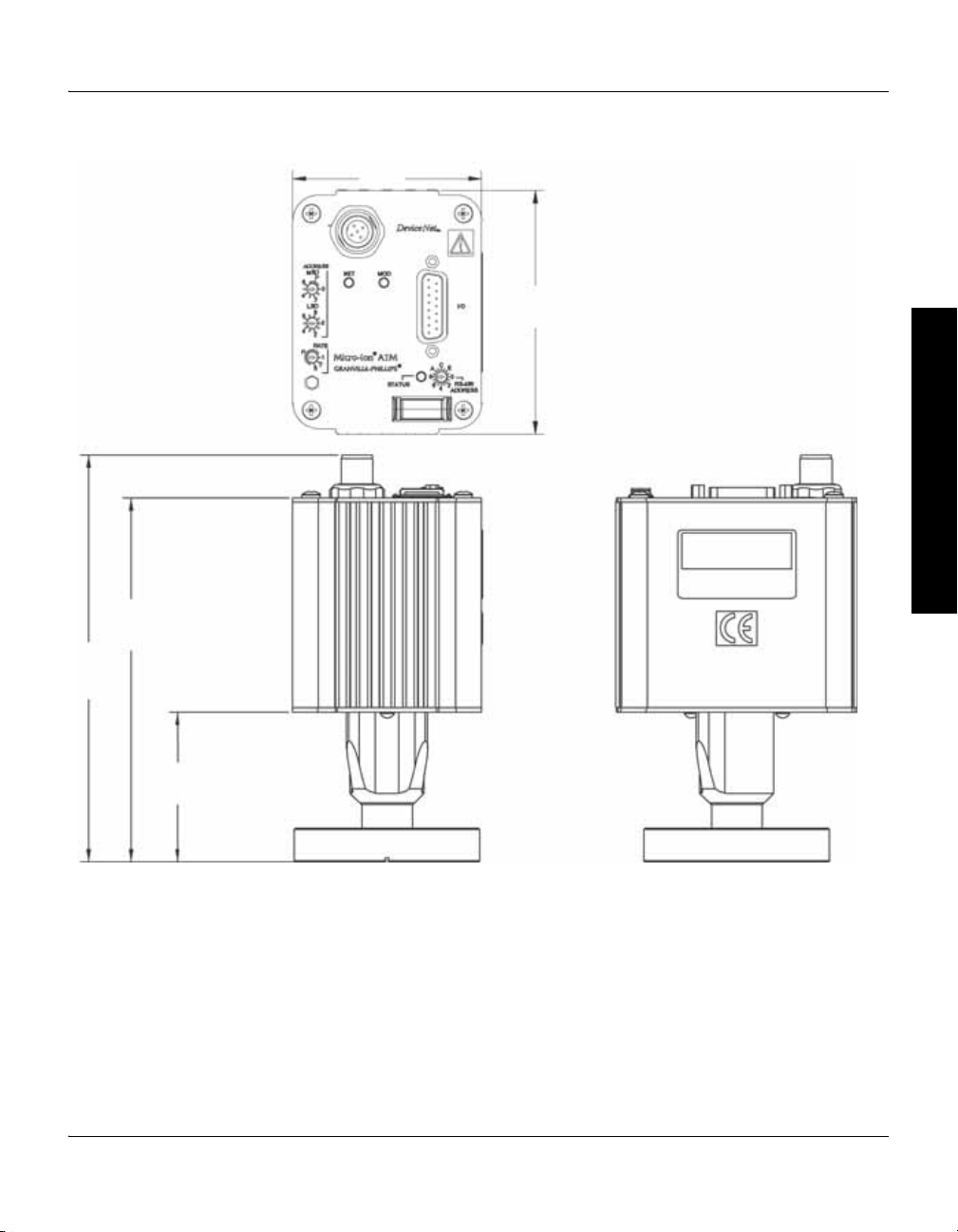
Figure 2-1 Dimensions
Dimensions in
cm
(in.)
7.1
(2.8)
9.1
(3.6)
15.1
(6)
13.6
(5.3)
5.6
(2.2)
Installation
Before You Begin Installation Operation Overview Analog Operation
Micro-Ion®ATM Module Instruction Manual - 390002 - Rev. E 17
Chapter 2
CAUTION
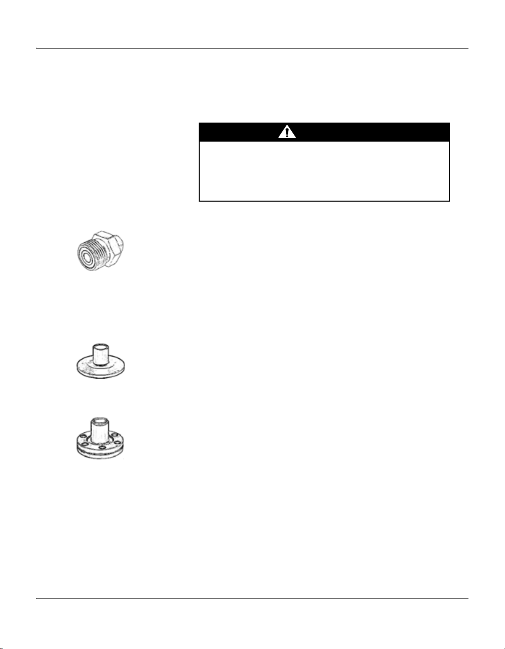
Step 2 Attach the module to the vacuum chamber
Attach the module’s flange/fitting to its mating fitting on the vacuum
chamber.
Twisting the module to tighten the fitting to the vacuum
chamber can damage the module’s internal connections.
• Do not twist the module to tighten the fitting.
• Use appropriate tools to tighten the fitting.
VCR type fitting VCR type fitting:
a. Remove the bead protector cap from the fitting.
b. Place the gasket into the female nut.
c. Assemble the components and tighten them to finger-tight.
d. While holding a back-up wrench stationary, tighten the female nut 1/8
turn past finger-tight on 316 stainless steel or nickel gaskets, or 1/4 turn
past finger-tight on copper or aluminum gaskets. Do not twist the
module to tighten the fitting.
KF flange The KF mounting system requires O-rings and centering rings between
mating flanges.
a. Tighten the clamp to compress the mating flanges together.
b. Seal the O-ring.
ConFlat flange To minimize the possibility of leaks with ConFlat
stainless steel bolts and a new, clean OFHC copper gasket. Avoid
scratching the seal surfaces. To avoid contamination, install new metal
gaskets.
a. Finger tighten all bolts.
b. Use a wrench to continue tightening 1/8 turn at a time in crisscross
order (1, 4, 2, 5, 3, 6) until flange faces make contact.
c. Further tighten each bolt about 1/16 turn.
18 Micro-Ion
®
flanges, use high strength
®
ATM Module Instruction Manual - 390002 - Rev. E

Step 3 Assemble and connect wiring
DeviceNet 5-pin micro connector
15-pin I/O connector
Connecting cable Cable is user-supplied. Brooks Automation does not supply cable. Install
externally shielded cable.
Wiring connects to the 15-pin I/O wiring connector or the DeviceNet 5-pin
micro connector. See Figure 2-2.
• Connect module power-supply wiring, analog output wiring, RS-485
output wiring, and relay wiring to the 15-pin connector.
• To turn the Micro-Ion gauge ON or OFF, install a switch between
terminals 3 and 5 on the 15-pin connector.
• To degas the Micro-Ion gauge, install a switch between terminals 7 and
8 on the 15-pin connector.
• Connect DeviceNet power-supply and network wiring to the DeviceNet
5-pin micro connector.
Figure 2-2 15-pin I/O connector and DeviceNet 5-pin micro connector
Installation
Before You Begin Installation Operation Overview Analog Operation
Micro-Ion®ATM Module Instruction Manual - 390002 - Rev. E 19

Chapter 2
CE Mark compliance
For CE mark compliance, use the following cable types (or equivalent):
Cable to 15-pin I/O connector
For the cable that connects to the 15-pin I/O connector, install shielded
cable with aluminum jacket and a tinned copper braid with a minimum of
65% coverage.
On the module end of the cable, install a metal housing, so the shield is
continuous from the cable to the gauge housing. Do not ground the shield
at the receiver or output device.
Acceptable raw cable parts:
• Belden cable 9947.
• Alpha cable 5110/15C SL005.
Acceptable connectors:
• Tyco series ADK for standard 15-pin subminiature-D connectors.
• Norcomp type 979-015-030-121.
DeviceNet cable
For DeviceNet cable, install raw cable that has a braided shield over the
aluminum foil-shielded signal and power wires.
On the module end of the cable, install a metal housing, so the shield is
continuous from the cable to the gauge housing. Do not ground the shield
at the receiver or output device.
• Acceptable raw cable is DeviceNet shielded cable type 578 from Turck.
• Acceptable connector is CM 8151-0 metal connector from Turck.
Module power supply Connect the module power supply to terminals 5 and 8 on the 15-pin I/O
wiring connector.
• Terminal 5 (ground) is negative (–).
• Terminal 8 (input) is positive (+).
The module requires 24 Vdc ±15% (1.5 A current at 20.4 V), 3.0 A current
at 30 W peak. Inrush current can momentarily exceed the 3.0 A peak.
Typical module operating power is 18 W for 4 mA emission when the
Micro-Ion gauge is ON.
Power inputs are reverse-bias protected.
The Micro-Ion gauge will not activate and an emission error will occur if
insufficient power is supplied during Micro-Ion gauge activation.
20 Micro-Ion
®
ATM Module Instruction Manual - 390002 - Rev. E
Installation
Gauge OFF/degas wiring Install a switch between terminals 3 and 5 and between terminals 7 and 8
to enable Micro-Ion gauge degas and to switch the Micro-Ion gauge ON or
OFF.
Before You Begin Installation Operation Overview Analog Operation
Relay, analog output, and RS-485 output wiring
• If the module has no trip point relays, see Figure 2-3.
• If the module has two trip point relays, see Figure 2-4. Relays are
normally open/normally closed.
• If the module has three trip point relays, see Figure 2-5. Relays are
normally open.
Relay contacts are silver alloy-gold clad, rated for 1 A at 30 Vdc. The relays
can handle resistive or non-inductive loads.
Figure 2-3 Wiring terminals for Micro-Ion ATM module with RS-485 interface, one analog output, and no trip-point relays
Figure 2-4 Wiring terminals for Micro-Ion ATM module with RS-485 interface, one analog output, and two trip-point relays
Figure 2-5 Wiring terminals for Micro-Ion ATM module with RS-485 interface, one analog output, and three trip-point relays
Micro-Ion®ATM Module Instruction Manual - 390002 - Rev. E 21
Chapter 2
CAN_H 4
Shield 1
3
(–) VDC return
2 (+) 24 VDC
5 CAN_L
WARNING
DeviceNet wiring
Figure 2-6 DeviceNet 5-pin micro connector
Grounding
The module has a DeviceNet 5-pin micro connector for interfacing through
the customer supplied DeviceNet network cable. See Figure 2-6. The
DeviceNet connection is a standard 5-pin DeviceNet receptacle that
accepts a standard micro 5-pin female cable connection.
The module will use terminals 2 (Vdc return) and 3 (24 Vdc) on the 5-pin
DeviceNet micro connector for the network power supply.
• The DeviceNet interface requires 24 Vdc (11 to 26.4) at 0.2 A maximum.
• Maximum inrush current is 0.25 A.
• Power inputs are reverse-bias protected.
The module contains three separate and isolated grounds: the DeviceNet
ground, the analog ground, and the chassis ground.
• Typical isolation between DeviceNet and chassis grounds is 1 MΩ, up to
26 Vdc, if the DeviceNet drain is grounded.
• Above 30 Vdc the isolation approaches 0 Ω.
• The analog ground is galvanically isolated from the DeviceNet ground
and the chassis ground up to 1500 V.
The module generates 180 Vdc during normal operation and 250 Vdc
during Micro-Ion gauge degas.
Improper grounding could cause severe product failure
or personal injury.
Follow ground network requirements for the facility.
• Maintain all exposed conductors at earth ground.
• Ground the module housing to the vacuum chamber as
illustrated below.
• Make sure the vacuum port to which the module is mounted
is properly grounded.
22 Micro-Ion
®
ATM Module Instruction Manual - 390002 - Rev. E
DeviceNet grounding
a. Bend the tab outward from the gauge base.
Vacuum chamber
b. Use the supplied nut to connect the
screw lug to the tab.
c. Connect the other screw lug to
the vacuum chamber.
The DeviceNet wiring will be properly grounded via the DeviceNet 5-pin
micro connector.
Chassis ground
If the module has a VCR type fitting or ConFlat flange, the module chassis
will be properly grounded via the vacuum chamber connection.
If the module has a KF flange, the module is shipped with a 3-foot length of
braided copper wire, which has a screw lug on each end, and a screw and
nut for connecting the copper wire to the gauge base. If a metal clamp and
metal gasket will not be installed, follow this procedure to ground the
module:
a. The gauge base has a tab that allows a connection to the copper wire.
b. Use the supplied screw and nut to connect one screw lug on the
c. Connect the other screw lug to an appropriately grounded point on the
Figure 2-7 Vacuum chamber ground connections
Installation
Before You Begin Installation Operation Overview Analog Operation
Bend the tab outward from the gauge base (see Figure 2-7).
braided copper wire to the tab.
vacuum system.
Micro-Ion®ATM Module Instruction Manual - 390002 - Rev. E 23

Chapter 2
Step 4 Calibrate module at atmospheric pressure
• To calibrate the module at atmospheric pressure using a momentary
switch installed between pins 15 and 5 on the 15-pin connector,
see page 35.
• To calibrate the module at atmospheric pressure using an RS–485
command, see page 99.
• To calibrate the module at atmospheric pressure using DeviceNet explicit
messaging, see page 65.
Atmospheric pressure calibration and differential pressure zero are
performed at the factory before the module is shipped. The module will not
operate properly unless you reset the atmospheric pressure calibration and
differential pressure zero at the ambient operating pressure.
2.4 Eliminating radio frequency interference
The module has been tested and found to comply with U.S. Federal
Communications Commission (FCC) limits for a Class A digital device,
pursuant to Part 15 of the FCC rules. These limits provide reasonable
protection against harmful interference when the module operates in a
commercial environment.
The module generates and can radiate radio frequency energy. If not
installed and used in accordance with the instructions in this manual, the
module may cause harmful interference to other electrical equipment.
24 Micro-Ion
®
ATM Module Instruction Manual - 390002 - Rev. E
Operation Overview
Chapter 3 Operation Overview
Before You Begin Installation Operation Overview Analog Operation
3.1 Interfaces, outputs, and relays
The module has a DeviceNet interface, an RS-485 interface, and one analog
output. The module may have no trip point relays, two trip point relays, or
three trip point relays.
3.2 Analog operation Table 3-1 lists tasks that may be performed using the analog output. The
output represents vacuum pressure. Using the analog output requires
installing switches on the 15-pin subminiature D connector. The switches
enable you to initiate or terminate the Micro-Ion gauge degas, calibrate the
module at atmospheric pressure, or calibrate the module at vacuum
pressure.
The analog output does not operate independently but must operate with
the DeviceNet or RS-485 interface.
Table 3-1 Tasks and page references for operation using the 15-pin subminiature D connector
Task Instructions:
Read vacuum pressure Page 31
Turn the Micro-Ion gauge OFF Page 32
Initiate or terminate Micro-Ion gauge degas Page 33
Calibrate module at atmospheric pressure Page 35
Calibrate module at vacuum pressure Page 35
3.3 DeviceNet operation • Table 3-2 lists tasks that may be performed using DeviceNet polled I/O.
• Table 3-3 lists tasks that may be performed using DeviceNet explicit
messages.
• For a complete list of DeviceNet messages used by the module, see
Appendix B.
Table 3-2 Tasks and page references for DeviceNet polled I/O
Task Instructions:
Read vacuum pressure Page 48
Read differential pressure Page 48
Turn OFF the Micro-Ion gauge Page 58
Initiate or terminate Micro-Ion gauge degas Page 62
Micro-Ion®ATM Module Instruction Manual - 390002 - Rev. E 25

Chapter 3
Table 3-3 Tasks and page references for DeviceNet explicit messages
Task Instructions:
Configure DeviceNet communications Page 43
Set or get pressure unit Page 47
Get vacuum pressure Page 48
Get differential pressure Page 48
Get temperature Page 51
Set relay trip points Page 51
Set relay activation direction Page 51
Set relay hysteresis Page 51
Set relay assignments Page 51
Set disabled/enabled state of relays Page 51
Get relay trip points Page 55
Get disabled/enabled state of relays Page 55
Get activation or deactivation status of relays Page 56
Get relay hysteresis Page 57
Get relay assignments Page 57
Set or get Micro-Ion gauge ON/OFF state Page 58
Set or get Micro-Ion gauge delay time Page 59
Set or get Micro-Ion gauge filament mode Page 60
Get Micro-Ion gauge active filament Page 61
Set or get Micro-Ion gauge degas ON/OFF state Page 62
Set or get emission current switch point for Micro-Ion gauge Page 63
Calibrate module at atmospheric pressure Page 65
Calibrate module at vacuum pressure Page 65
Reset module to power-up state Page 66
Get firmware version for module Page 66
Get software and hardware revisions for module Page 66
Get status alarms and warnings Page 115
26 Micro-Ion
®
ATM Module Instruction Manual - 390002 - Rev. E

Operation Overview
3.4 RS-485 operation Table 3-4 lists tasks that may be performed using the RS-485 output.
Table 3-4 Commands, tasks, and page references for RS-485 operation
Command Task Instructions:
TLU Toggle functions to locked or unlocked state Page 80
UNL Unlock interface functions Page 80
SA Set address offset Page 81
SB Set baud rate Page 82
yuiop Set RS–485 communication to default values Page 82
SU Set pressure unit Page 82
RU Read pressure unit Page 82
SD Set pressure indication for optional display Page 82
RD Read vacuum pressure Page 83
RDD Read differential pressure Page 83
PC Set or read relay trip points and activation direction Page 84
PCG Set relay assignments Page 87
PCE Set or read disabled/enabled state of relays Page 87
RPCS Read activation or deactivation status of relays Page 88
IG Set Micro-Ion gauge ON/OFF state Page 88
IGS Read Micro-Ion gauge ON/OFF state Page 88
IGM Set or read gauge and sensor ON/OFF mode Page 89
IOD Set Micro-Ion gauge delay ON/OFF state Page 90
IDT Set Micro-Ion gauge delay time Page 91
SF Set Micro-Ion gauge filament mode Page 92
RF Read Micro-Ion gauge filament status Page 96
DG Set Micro-Ion gauge degas ON/OFF state Page 96
DGS Read Micro-Ion gauge degas ON/OFF state Page 96
DGT Set or read Micro-Ion gauge degas time Page 97
SER Set emission current switch point for Micro-Ion gauge Page 97
RE Read Micro-Ion gauge emission current Page 99
TS Calibrate module at atmospheric pressure Page 99
TZ Calibrate module at vacuum pressure Page 100
ATM Set or read atmospheric pressure indicated by analog and RS–485 outputs Page 101
RS Read RS-485 character strings indicating module status Page 101
RSX Read 8-digit hexadecimal codes indicating module status Page 103
RST Reset module to power-up state Page 105
FAC Reset values to factory defaults Page 106
VER Read firmware version for module Page 106
Before You Begin Installation Operation Overview Analog Operation
Micro-Ion®ATM Module Instruction Manual - 390002 - Rev. E 27

Chapter 3
3.5 Automatic filament selection
As the vacuum system pumps down from atmosphere, the Conductron
sensor measures pressure until a sufficiently low pressure level is achieved,
then automatically turns ON the Micro-Ion gauge. The filaments in the
Micro-Ion gauge can burn out if they turn ON at a pressure that is too high.
Tungsten filaments are more likely than yttria-coated iridium filaments to
burn out if they turn ON at a pressure that is too high. To reduce the risk of
burnout, the default behavior of Micro-Ion gauge depends on the filament
material.
If a rapid increase in pressure from high vacuum levels to pressures of 1 Torr
(1.33 mbar, 133 Pa) or higher pressure occurs, tungsten filaments are almost
certain to burn out. This risk is not unique to the Micro-Ion gauge and exists
for all ion gauges containing tungsten filaments.
• At startup, the module software detects the filament material and sets the
behavior of the Micro-Ion gauge accordingly, as listed in Table 3-5.
• If the gauge assembly is replaced, the module software automatically sets
the behavior of the Micro-Ion gauge according to the filament material.
• For RS-485 communications, you can use the IOD, IDT, and SF
commands to change the behavior of the Micro-Ion gauge. See pages
90–92.
• For DeviceNet communications, you can use explicit messages to
change the behavior of the Micro-Ion gauge. See pages 60–61.
Table 3-5 Defaults for Micro-Ion gauge filament material
Function Default for tungsten filaments Default for yttria-coated iridium filaments
Micro-Ion gauge delay time Module software determines the
appropriate amount of time to
wait before the Micro-Ion gauge
turns ON with decreasing
pressure
Micro-Ion gauge added delay time Micro-Ion gauge waits an
additional 2 seconds, beyond
software-defined delay time, to
turn ON with decreasing
pressure.
Micro-Ion gauge filament mode Manual (see page 60 or page 94). Alternating (see page 60 or page 95).
Micro-Ion gauge turns ON, without delay,
as soon as operational pressure is achieved
with decreasing pressure.
28 Micro-Ion
®
ATM Module Instruction Manual - 390002 - Rev. E
Analog Operation
WARNING
Chapter 4 Analog Operation
4.1 Output functions The module has a DeviceNet interface, an RS-485 interface, and one
analog output. The analog output represents vacuum pressure.
The analog output does not operate independently but must operate with
the DeviceNet or RS-485 interface.
Using the module to measure the pressure of flammable
or explosive gases can cause a fire or explosion resulting
in severe property damage, personal injury, or death.
Do not use the module to measure the pressure of flammable or
explosive gases.
Before You Begin Installation Operation Overview Analog Operation
4.2 Preparing to operate the module
4.3 Operational tasks Once the module is operating, you may perform the tasks listed in Table 3-1
Before putting the module into operation, you must perform the following
procedures:
1. Install the module in accordance with the instructions on pages 15–24.
2. Develop a logic diagram of the process control function.
3. Develop a circuit schematic that specifies exactly how each piece of
system hardware will connect to the module relays.
4. Attach a copy of the process control circuit diagram to this manual for
future reference and troubleshooting.
If you need application assistance, phone a Granville-Phillips application
engineer at 1-303-652-4400 or 1-800-776-6543 within the USA, or email
co-csr@brooks.com.
on page 25.
Micro-Ion®ATM Module Instruction Manual - 390002 - Rev. E 29
Chapter 4
Status LED
4.4 LED status indicator
Figure 4-1 LED status indicator
• Figure 4-1 illustrates the LED status indicator on the top of the housing.
The LED behavior indicates the status of the module and Micro-Ion
gauge.
• Table 4-1 lists states indicated by the LED.
Table 4-1 LED status indications
LED behavior Indicated condition:
OFF Module power supply is OFF
Solid green Power is ON, Micro-Ion gauge is OFF
Blinking green Micro-Ion gauge is ON
Solid amber Micro-Ion gauge is ON but one filament is inoperable
Blinking amber • Both Micro-Ion gauge filaments are inoperable; replace gauge assembly
• Electronics may be defective; return module to factory
30 Micro-Ion
®
ATM Module Instruction Manual - 390002 - Rev. E
 Loading...