

Granville-Phillips Micro-Ion 354 E Series, Micro-Ion 354010E-YD-T, Micro-Ion 354001E-YD-T Instruction Manual

Series 354
Granville-Phillips® Micro-Ion® E
Vacuum Gauge Module with
Analog or RS–232 Output
Instruction Manual
Instruction manual part number 354011E
Revision A - October 2013


Series 354
Granville-Phillips® Micro-Ion® E
Vacuum Gauge Module with
Analog or RS–232 Output
This Instruction Manual is for use with all Granville-Phillips
Series 354 Micro-Ion Vacuum Gauge Modules with analog
output. A list of applicable catalog numbers is provided on
the following page.
Customer Service/Support
For customer service within USA, 8 AM to 5 PM
Mountain Time Zone, weekdays excluding holidays:
Granville-Phillips
6450 Dry Creek Parkway
Longmont, CO 80503 USA
Phone: +1-800-776-6543
Phone: +1-303-652-4400
FAX: +1-303-652-2844
Email: co-csr@brooks.com
Brooks Automation, Inc.
15 Elizabeth Drive
Chelmsford, MA 01824 USA
Phone: +1-978-262-2400
For customer service, 24 hours per day, 7 days per week,
every day of the year including holidays within the USA:
Phone: +1-800-367-4887
www.brooks.com
Instruction Manual
© 2013 Brooks Automation, Inc. All rights reserved. Granville-Phillips® and Micro-Ion® are
registered trademarks of Brooks Automation, Inc. All other trademarks and registered
trademarks are the properties of their respective owners.

Granville-Phillips® Series 354 Micro-Ion® Vacuum Gauge
Module with Analog Output or RS-232 Digital Interface
Catalog Numbers for Series 354 Micro-Ion Modules - CE Marked
Power supply and cable are not included.
Analog Output 354001E - Y D - T
RS-232 Interface 354010E - Y D - T
Filament: Yttria-Coated Iridium Y
Fitting: NW16KF D
Measurement Unit: Torr T

Contents
Chapter 1 Safety & Introduction . . . . . . . . . . . . . . . . . . . . . . . . . . . . . . . . . 7
1.1 About These Instructions . . . . . . . . . . . . . . . . . . . . . . . . . . . 7
1.2 Caution and Warning Statements . . . . . . . . . . . . . . . . . . . . 7
1.3 Reading and Following Instructions . . . . . . . . . . . . . . . . . . 8
1.4 Definitions of Terms . . . . . . . . . . . . . . . . . . . . . . . . . . . . . . 8
1.5 Service Guidelines . . . . . . . . . . . . . . . . . . . . . . . . . . . . . . . 9
Chapter 2 Installation . . . . . . . . . . . . . . . . . . . . . . . . . . . . . . . . . . . . . . . . . . 11
2.1 Module Components . . . . . . . . . . . . . . . . . . . . . . . . . . . . . 11
2.2 Pressure Relief Devices . . . . . . . . . . . . . . . . . . . . . . . . . . . . 11
2.3 Installation Procedure . . . . . . . . . . . . . . . . . . . . . . . . . . . . . 11
Step 1 Locate the module . . . . . . . . . . . . . . . . . . . . . . . . . . . . . . . 12
Step 2 Attach module to vacuum chamber . . . . . . . . . . . . . . . . . . 13
Step 3 Assemble and connect wiring . . . . . . . . . . . . . . . . . . . . . . . 13
Connecting Cable . . . . . . . . . . . . . . . . . . . . . . . . . . . . . . . . 13
Power Supply . . . . . . . . . . . . . . . . . . . . . . . . . . . . . . . . . . . 13
Wiring for Analog Module . . . . . . . . . . . . . . . . . . . . . . . . . 14
Wiring for RS–232 Module . . . . . . . . . . . . . . . . . . . . . . . . . 15
Grounding . . . . . . . . . . . . . . . . . . . . . . . . . . . . . . . . . . . . . 15
2.4 Eliminating Radio Frequency Interference . . . . . . . . . . . . . . 16
Chapter 3 Operation Overview . . . . . . . . . . . . . . . . . . . . . . . . . . . . . . . . . . 17
3.1 Analog versus RS–232 Operation Procedures . . . . . . . . . . . 17
3.2 Analog Operation . . . . . . . . . . . . . . . . . . . . . . . . . . . . . . . . 17
3.3 RS–232 Operation . . . . . . . . . . . . . . . . . . . . . . . . . . . . . . . 18
Chapter 4 Analog Operation . . . . . . . . . . . . . . . . . . . . . . . . . . . . . . . . . . . . . 19
4.1 Output Functions . . . . . . . . . . . . . . . . . . . . . . . . . . . . . . . . 19
4.2 Preparing to Operate the Module . . . . . . . . . . . . . . . . . . . . 19
4.3 Operational Tasks . . . . . . . . . . . . . . . . . . . . . . . . . . . . . . . . 19
4.4 Turn the Micro-Ion E Gauge ON or OFF . . . . . . . . . . . . . . . 20
4.5 Micro-Ion E Gauge ON/OFF Status . . . . . . . . . . . . . . . . . . . 21
4.6 LED Status Indicator . . . . . . . . . . . . . . . . . . . . . . . . . . . . . . 21
4.7 Reading Vacuum Pressure . . . . . . . . . . . . . . . . . . . . . . . . . . 22
or Air Pressure . . . . . . . . . . . . . . . . . . . . . . . . . . . . . . . . 22
N
2
Correction Factor . . . . . . . . . . . . . . . . . . . . . . . . . . . . . . . . 23
4.8 Overpressure Limit . . . . . . . . . . . . . . . . . . . . . . . . . . . . . . . 23
Chapter 5 RS–232 Operation . . . . . . . . . . . . . . . . . . . . . . . . . . . . . . . . . . . 25
5.1 Output Functions . . . . . . . . . . . . . . . . . . . . . . . . . . . . . . . . 25
5.2 Preparing to Operate the Module . . . . . . . . . . . . . . . . . . . . 25
5.3 Operational Tasks . . . . . . . . . . . . . . . . . . . . . . . . . . . . . . . . 25
Micro-Ion E Module Instruction Manual 354011, Rev. A 5

Contents
5.4 Error Responses . . . . . . . . . . . . . . . . . . . . . . . . . . . . . . . . . . 26
5.5 RS–232 Commands . . . . . . . . . . . . . . . . . . . . . . . . . . . . . . . 27
5.6 RS–232 Command Set . . . . . . . . . . . . . . . . . . . . . . . . . . . . 27
UNL Unlock Interface Functions . . . . . . . . . . . . . . . . . . . . . . . . . 27
TLU Toggling Locked Functions . . . . . . . . . . . . . . . . . . . . . . . . . 28
SB Set Baud Rate . . . . . . . . . . . . . . . . . . . . . . . . . . . . . . . . . . . 28
FAC Reset Baud Rate to Factory Defaults . . . . . . . . . . . . . . . . . . 30
IG Turn Micro-Ion E Gauge ON or OFF . . . . . . . . . . . . . . . . . . 30
IGS Read Micro-Ion E Gauge ON/OFF Status . . . . . . . . . . . . . . 31
RD Read Vacuum Pressure . . . . . . . . . . . . . . . . . . . . . . . . . . . . 32
or Air Pressure . . . . . . . . . . . . . . . . . . . . . . . . . . . . . . . . 32
N
2
Correction Factor . . . . . . . . . . . . . . . . . . . . . . . . . . . . . . . . 32
SO Set Overpressure Limit . . . . . . . . . . . . . . . . . . . . . . . . . . . . 33
RST Reset Module to Programmed Values . . . . . . . . . . . . . . . . . 33
RS Read Module Status . . . . . . . . . . . . . . . . . . . . . . . . . . . . . . 33
VER Read Firmware Version . . . . . . . . . . . . . . . . . . . . . . . . . . . . 34
Chapter 6 Maintenance . . . . . . . . . . . . . . . . . . . . . . . . . . . . . . . . . . . . . . . . . 35
6.1 Customer Service . . . . . . . . . . . . . . . . . . . . . . . . . . . . . . . . 35
Damage Requiring Service . . . . . . . . . . . . . . . . . . . . . . . . . 35
6.2 Troubleshooting . . . . . . . . . . . . . . . . . . . . . . . . . . . . . . . . . 35
Precautions . . . . . . . . . . . . . . . . . . . . . . . . . . . . . . . . . . . . . 35
Symptoms, Causes, and Solutions . . . . . . . . . . . . . . . . . . . . 36
RS–232 Error Responses . . . . . . . . . . . . . . . . . . . . . . . . . . . 38
6.3 Micro-Ion E Gauge Continuity Test . . . . . . . . . . . . . . . . . . . 39
6.4 Service Guidelines . . . . . . . . . . . . . . . . . . . . . . . . . . . . . . . 41
Appendix A Specifications . . . . . . . . . . . . . . . . . . . . . . . . . . . . . . . . . . . . . . . . 43
Appendix B Theory of Operation . . . . . . . . . . . . . . . . . . . . . . . . . . . . . . . . . . 47
Index . . . . . . . . . . . . . . . . . . . . . . . . . . . . . . . . . . . . . . . . . . . . . . . . . . . . . . . . . . . . . . . . . . . . . . . . . . . . . 49
6 Micro-Ion E Module Instruction Manual 354011, Rev. A
Chapter 1 Safety & Introduction
WARNING
Safety & Introduction Installation Operation Overview Analog Operation MaintenanceRS-232 Operation
1.1 About These Instructions These instructions explain how to install, operate, and maintain the
Granville-Phillips
The module may have an analog output or an RS–232 output. Installation
and operating procedures depend on the output.
• This chapter explains caution and warning statements, which must be
adhered to at all times; explains your responsibility for reading and
following all instructions; defines the terms that are used throughout this
instruction manual; and explains how to contact customer service.
• Chapter 2 explains how to install the module.
• Chapter 3 is an operational overview of the module.
• Chapter 4 explains analog module operation.
• Chapter 5 explains RS–232 module operation.
• Chapter 6 explains troubleshooting; Micro-Ion E gauge testing, removal
and replacement; and module return procedures.
• Appendix A provides specifications for the module.
• Appendix B explains how the Micro-Ion E gauge measures pressure.
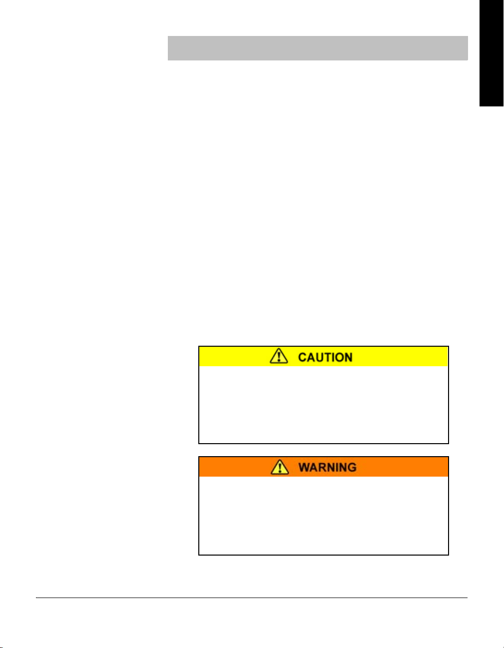
1.2 Caution and Warning Statements
This manual contains caution and warning statements with which you must
comply to prevent inaccurate measurement, property damage, or personal
injury.
®
Micro-Ion® E vacuum gauge module.
Caution statements alert you to hazards or unsafe
practices that could result in inaccurate measurement,
minor personal injury or property damage.
Each caution statement explains what you must do to prevent or
avoid the potential result of the specified hazard or unsafe
practice.
Warning statements alert you to hazards or unsafe
practices that could result in severe property damage or
personal injury due to electrical shock, fire, or explosion.
Each warning statement explains what you must do to prevent
or avoid the potential result of the specified hazard or unsafe
practice.
Micro-Ion E Module Instruction Manual 354011, Rev. A 7
Chapter 1
Caution and warning statements comply with American Institute of
Standards Z535.1–2002 through Z535.5–2002, which set forth voluntary
practices regarding the content and appearance of safety signs, symbols,
and labels.
Each caution or warning statement explains:
a. The specific hazard that you must prevent or unsafe practice that you
must avoid,
b. The potential result of your failure to prevent the specified hazard or
avoid the unsafe practice, and
c. What you must do to prevent the specified hazardous result.
1.3 Reading and Following Instructions
You must comply with all instructions while you are installing, operating,
or maintaining the module. Failure to comply with the instructions violates
standards of design, manufacture, and intended use of the module. Brooks
Automation / Granville-Phillips disclaim all liability for the customer's
failure to comply with the instructions.
• Read instructions – Read all instructions before installing or operating the
product.
• Follow instructions – Follow all installation, operating and maintenance
instructions.
• Retain instructions – Retain the instructions for future reference.
• Heed warnings and cautions – Adhere to all warnings and caution
statements on the product and in these instructions.
• Parts and accessories – Install only those replacement parts and
accessories that are recommended by Brooks Automation /
Granville-Phillips. Substitution of parts is hazardous.
1.4 Definitions of Terms The terms listed in Table 1-1 are used throughout this manual in reference
to the Micro-Ion E vacuum gauge module.
Table 1-1 Terms Describing the Micro-Ion E Module and Components
Term Description
Module The entire Micro-Ion E module, which includes the housing, gauge assembly,
electronics, and vacuum chamber fitting.
Gauge assembly A removable assembly that contains a hot filament Micro-Ion gauge
Micro-Ion E gauge The Bayard-Alpert type ionization gauge, which indicates pressure by producing
(Bayard-Alpert type ionization gauge).
a current that is proportional to gas density.
8 Micro-Ion E Module Instruction Manual 354011, Rev. A

Safety & Introduction
1.5 Service Guidelines Some minor problems are readily corrected on site. If the product requires
service, please contact our Customer Service Department at 303-652-4400
for troubleshooting help over the phone.
If the module must be returned to the factory for service, request a Return
Materials Authorization (RMA) from Brooks Automation /
Granville-Phillips. Do not return products without first obtaining an RMA.
In some cases a hazardous materials document may be required. The
Brooks Automation / Granville-Phillips Customer Service Representative
will advise you if the hazardous materials document is required.
When returning equipment to Brooks Automation / Granville-Phillips, be
sure to package the products to prevent shipping damage. Circuit boards
and modules separated from the controller chassis must be handled using
proper anti-static protection methods and must be packaged in anti-static
packaging. Brooks Automation / Granville-Phillips will supply return
packaging materials at no charge upon request. Shipping damage on
returned products as a result of inadequate packaging is the Buyer's
responsibility. Before you return the module, obtain an RMA number by
contacting Granville-Phillips customer service:
• Phone 1-303-652-4400 or 1-800-776-6543 within the USA.
• Phone 1-800-367-4887 24 hours per day, seven days per week
within the USA.
• Email co-csr@brooks.com
• For Global Customer Support, go to www.brooks.com and click on
Services to locate the Brooks Automation office nearest you.
Before You Begin Installation Operation Overview Analog Operation MaintenanceRS-232 Operation
Micro-Ion E Module Instruction Manual 354011, Rev. A 9

10 Micro-Ion E Module Instruction Manual 354011, Rev. A
Chapter 2 Installation
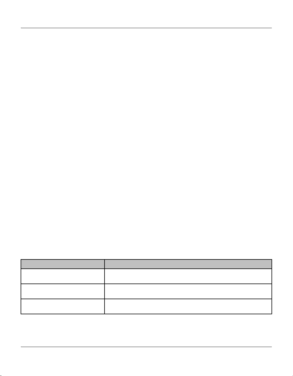
2.1 Module Components The Micro-Ion E module houses a a Micro-Ion E gauge (Bayard-Alpert type
ionization gauge).
Using the module to measure the pressure of flammable
or explosive gases can cause a fire or explosion resulting
in severe property damage or personal injury.
Do not use the module to measure the pressure of flammable or
explosive gases.
Exposing the module to moisture can cause fire or
electrical shock resulting in severe property damage or
personal injury.
To avoid exposing the module to moisture, install the module in
an indoor environment. Do not install the module in any
outdoor environment.
Before You Begin Installation Operation Overview Analog Operation MaintenanceRS-232 Operation
2.2 Pressure Relief Devices Before you install the module, you should install appropriate pressure relief
devices in the vacuum system.
Brooks Automation / Granville-Phillips does not supply pressure relief
valves or rupture disks. Suppliers of pressure relief valves and rupture disks
are listed in the Thomas Register under “Valves, Relief” and “Discs,
Rupture.”
2.3 Installation Procedure The module installation procedure includes the following steps:
1. Locating the module.
2. Attaching the module vacuum chamber fitting to its mate on the
vacuum chamber.
3. Assembling and connecting module wiring.
This chapter also explains what to do if radio frequency interference (RFI)
disrupts operation of RS–232 version of the module.
Micro-Ion E Module Instruction Manual 354011, Rev. A 11
Chapter 2
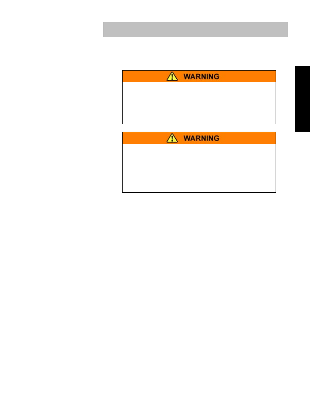
Dimensions
are in inches
Figure 2-1 Dimensions
Step 1 Locate the module
To locate the module, refer to Figure 2-1 and follow the guidelines below.
• Locate the module where it can be easily accessed.
• For greatest accuracy and repeatability, locate the module in a stable,
room-temperature environment. Ambient temperature should never
exceed 40 °C (104 °F) operating, non-condensing, or 85 °C (185 °F)
non-operating. Bakeout temperature with the electronics removed from
the module is 200 °C (392 °F).
• Locate the module away from internal and external heat sources and in
an area where ambient temperature remains reasonably constant.
• Do not locate the module near the pump, where gauge pressure might be
lower than normal vacuum pressure.
• Do not locate the module near a gas inlet or other source of
contamination.
• Do not locate the module where it will be exposed to corrosive gases
such as mercury vapor or fluorine.
12 Micro-Ion E Module Instruction Manual 354011, Rev. A
Installation
Step 2 Attach module to vacuum chamber
Attach the module vacuum chamber fitting to its mate on the vacuum
chamber.
Twisting the module to tighten the fitting to the vacuum
chamber can damage the module’s internal connections.
• Do not twist the module to tighten the fitting.
• Use appropriate tools to tighten the fitting.
The NW16KF flange requires O-rings and centering rings between mating
flanges.
a. Tighten the clamp to compress the mating flanges together.
b. Seal the O-ring.
Step 3 Assemble and connect wiring
Connecting Cable Cable is user-supplied. Brooks Automation / Granville-Phillips does not
supply cable. Install externally shielded cable.
• Connect the shield at both ends of the cable.
• At the module end of the cable, connect the shield to the outer shell of
the subminiature D connector.
Before You Begin Installation Operation Overview Analog Operation MaintenanceRS-232 Operation
Power Supply Power supply requirement is 24 Vdc ±15%, 12 W maximum.
Micro-Ion E Module Instruction Manual 354011, Rev. A 13
Chapter 2
Not used
24 Vdc power input (+)
Analog output (+)
24 Vdc power ground (–)
Micro-Ion E gauge ON/OFF (+)
Micro-Ion E gauge status
Not used
Analog output ground (–)
Not used
Male pins
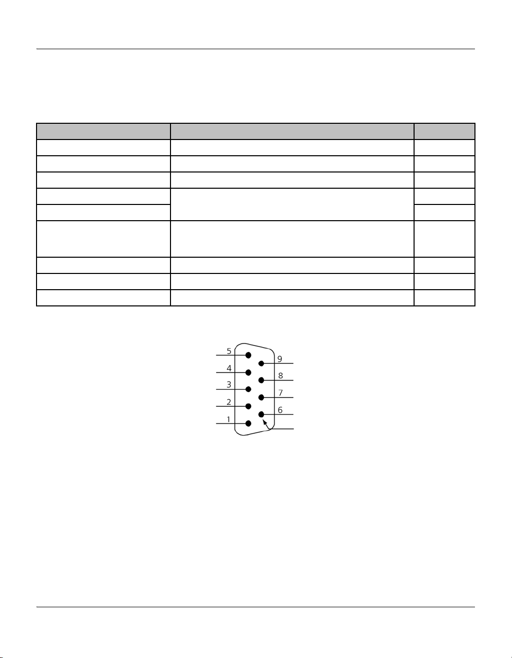
Wiring for Analog Module
• If the module has an analog output, see Figure 2-2.
• Table 2-1 lists pin designations for the 9-pin subminiature D connector.
Table 2-1 Wiring Pin Designations for Analog Module
Pin designation Function Pin number
Micro-Ion E gauge ON/OFF (+) Switch between pins 1 and 2 turns Micro-Ion E gauge ON or OFF 1
24 Vdc power supply ground (–) Negative connection for 24 Vdc power supply 2
Power supply input (+) Positive connection for 24 Vdc power supply 4
Analog output (+) Analog output produces a 0 to 10 Vdc output in linear proportion
Analog output ground (–) 7
Micro-Ion E gauge status
(40 Vdc, 50 mA maximum)
Not used Reserved 5
Not used Reserved 6
Not used Reserved 8
Figure 2-2 WiringTerminals for Micro-Ion E Module with Analog Output
to the logarithm of vacuum pressure
Open collector transistor output indicates Micro-Ion E gauge status
• Output is high (“source”) when Micro-Ion E gauge is OFF
• Output is low (“sink”) when Micro-Ion E gauge is ON
3
9
14 Micro-Ion E Module Instruction Manual 354011, Rev. A
Installation
RS–232 common
Not used
RS–232 RDX
RS–232 TDX
Chassis ground
24 Vdcpower ground (–)
24 Vdcpower input (+)
Not used
Not used
Male pins
Before You Begin Installation Operation Overview Analog Operation MaintenanceRS-232 Operation
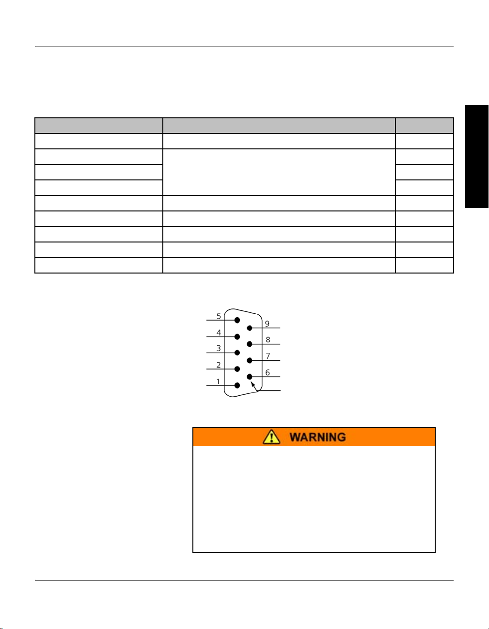
Wiring for RS–232 Module
Table 2-2 Wiring Pin Designations for RS–232 Module
Pin designation Function Pin number
Chassis ground Ground connection for module chassis 1
RS–232 TDX • Pins 2, 3, and 5 enable RS–232 digital communication
RS–232 RDX 3
RS–232 common 5
Not used Reserved 4
Not used Reserved 6
Not used Reserved 7
24 Vdc power supply input (+) Positive connection for 24 Vdc power supply 8
24 Vdc power supply ground (–) Negative connection for 24 Vdc power supply 9
Figure 2-3 Wiring Terminals for Micro-Ion E Module with RS–232 Output
• If the module has an RS–232 output, see Figure 2-3.
• Table 2-2 lists pin designations for the 9-pin subminiature D connector.
2
• Pins, 2, 3, and 5 connect to computer communication port
Grounding
Improper grounding could cause severe product failure
or personal injury.
Follow ground network requirements for the facility.
• Maintain all exposed conductors at earth ground.
• Ground the module housing to the vacuum chamber as
illustrated below.
Micro-Ion E Module Instruction Manual 354011, Rev. A 15
• Make sure the vacuum port to which the module is mounted
is properly grounded.

Chapter 2
Metal hose clamp or
other metal clamp
3.31 mm
2
(12 AWG)
or larger ground wire
Vacuum Chamber
Ground lug, bolt, or stud
Gauge stem
If the analog module has a VCR type fitting or ConFlat flange, the module
will be properly grounded via the vacuum chamber connection.
If the analog or RS–232 module has a KF flange, refer to Figure 2-4 and
follow these instructions to ground the module to the vacuum chamber:
a. Attach a metal hose clamp or other metal clamp to the gauge stem of
b. Install a 3.31 mm
Figure 2-4 Vacuum Chamber Ground Connection
the housing.
2
(12 AWG) or larger copper wire between the clamp
and a metal ground lug, bolt, or stud on the vacuum chamber.
2.4 Eliminating Radio Frequency Interference
The module has been tested and found to comply with U.S. Federal
Communications Commission (FCC) limits for a Class A digital device,
pursuant to Part 15 of the FCC rules. These limits provide reasonable
protection against harmful interference when the module operates in a
commercial environment.
The module can radiate radio frequency energy and, if not installed and
used in accordance with the instructions in this manual, may cause harmful
interference to other electrical equipment.
16 Micro-Ion E Module Instruction Manual 354011, Rev. A
Chapter 3 Operation Overview
Before You Begin Installation Operation Overview Analog Operation MaintenanceRS-232 Operation
3.1 Analog versus RS–232 Operation Procedures
The module may have an analog output or an RS–232 output. The operating
procedure depends on the output.
Using the module to measure the pressure of flammable
or explosive gases can cause a fire or explosion resulting
in severe property damage, personal injury, or death.
Do not use the module to measure the pressure of flammable or
explosive gases.
3.2 Analog Operation If the module has an analog output, the operation procedure includes
reading pressure, using the switches installed between wiring pins 1 and 2
(Micro-Ion E gauge ON/OFF), and reading Micro-Ion E gauge ON/OFF
status.
Table 3-1 lists tasks that may be performed if the module has an analog
output.
Table 3-1 Tasks and Page References for Analog Operation
Task Instructions:
Turn the Micro-Ion E gauge ON or OFF Page 20
Read Micro-Ion E gauge ON/OFF status Page 21
Read vacuum pressure Page 22
Micro-Ion E Module Instruction Manual 354011, Rev. A 17
 Loading...