

Granville-Phillips 835 Series Instruction Manual

Series 835
Granville-Phillips® Series 835
Vacuum Quality Monitor
TM
Instruction Manual
Instruction manual part number 835000
Revision E - August 2013

Series 835
Granville-Phillips® Series 835
Vacuum Quality Monitor
This Instruction Manual is for use with all Series 835
Vacuum Quality Monitors. A list of applicable catalog
numbers is provided on the following page.
This product is RoHS compliant.
TM
Customer Service/Support
For customer service within USA, 8 AM to 5 PM
Mountain Time Zone, weekdays excluding holidays:
Granville-Phillips
6450 Dry Creek Parkway
Longmont, CO 80503 USA
Phone: +1-800-776-6543
Phone: +1-303-652-4400
FAX: +1-303-652-2844
Email: co-csr@brooks.com
Brooks Automation, Inc.
15 Elizabeth Drive
Chelmsford, MA 01824 USA
Phone: +1-978-262-2400
For customer service, 24 hours per day, 7 days per week,
every day of the year including holidays within the USA:
Phone: +1-800-367-4887
World Wide Web: www.brooks.com
www.brooks.com/vqm
Instruction Manual
© 2013 Brooks Automation, Inc. All rights reserved.
Granville-Phillips
TM
, Vacuum Quality IndexTM, and Vacuum Quality Monitor
VQI
Automation, Inc.
All other trademarks and registered trademarks are the properties of their respective owners.
®
, VQM®, and Micro-Ion® are registered trademarks of Brooks Automation, Inc.
TM
are trademarks of Brooks

Catalog numbers for Series 835 VQM® Controllers, Gauges, and Accessories
Product/Description Catalog Number
VQM Controller for one MS Gauge, benchtop mount . . . . . . . . . . 835500-U#-#(*)
USB 2.0, 1-145 or 1-300 amu, with power supply & cord.
1 = 1 - 145 amu (120 resolution)
3 = 1 - 300 amu (180 resolution)
Cables, VQM Controller to Mass Spectrometer Gauge: . . . . . . . 835300-##M(**)
835 Software Suite (Viewer Application, LabVIEW VI). . . . . . . . . . . . . . . 835400
835 MS Gauge, Channel Electron Multiplier Detector . . . . . . . . . . 835100-YG-# X
Y = Yttria-coated Iridium filament
G = 2.75inch (NW35CF) flange
1 = 1 - 145 amu
3 = 1 - 300 amu
N = Nude
Total Pressure Measurement Micro-Ion ATM Module. . . . . . . . . . . 390802-2-YG-T
Absolute & Ratiometric Pressure, 10-9 to ATM, RS-485,
gauge filament protection, digital display, dual Yttria-coated Iridium
ion gauge filaments, 2.75-inch (NW35CF) ConFlat-type flange, Torr
D = In demountable envelope
Cables - 835 VQM Controller to Micro-Ion ATM Module: . . . . 802301-##M(***)
Accessories
Field Replaceable Filament Assembly Kit:. . . . . . . . . . . . . . . . . . . . . . 830105-Y-K
For use with Series 830 & 835 Gauges.
Field Replaceable Electron Multiplier Kit: . . . . . . . . . . . . . . . . . . . . . . 835110-K
For use with Series 835 Gauges only.
Cable for log/linear analog output (1/8" miniature phone jack) . . . . . .801202-10M
Interconnect from a G-P Series 370 Ion Gauge Controller
to the analog input on the VQM Controller, 10 meters long
Demountable Envelope (4-inch nipple) for Nude Gauge . . . . . . . . . . . . . 801270
T-Flange, 2.75 inch (NW35CF) flanges . . . . . . . . . . . . . . . . . . . . . . . . . . . 801272
Hardware/Bolt Kit: . . . . . . . . . . . . . . . . . . . . . . . . . . . . . . . . . . . . . . . . 801274-1
Includes 6 flange bolts and washers, 3 plate nuts, and 1 copper gasket
Wrench, 1/4", 12 pt.. . . . . . . . . . . . . . . . . . . . . . . . . . . . . . . . . . . . . . . . . . 801275
Heater Jacket
Heater Jacket
, 120 VAC, for the 835 Gauge:. . . . . . . . . . . . . . . . . . . . . . . 801203-1
, 240 VAC, for the 835 Gauge:. . . . . . . . . . . . . . . . . . . . . 801204-#(*)
(*) # -1 = North American 115 VAC & Japan 100 VAC, -2 = North American 240 VAC,
-3 = Universal European 220 VAC, -4 = United Kingdom 240 VAC
(**) # -01 = 1 meter (3.28 ft), -03 = 3 meters (9.84 ft), -20 = 20 meters (65.6 ft)
(***) # -01 = 1 meter (3.28 ft), -03 = 3 meters (9.84 ft)
Windows, Windows XP, and Windows 7 are registered trademarks of Microsoft Corporation.
LabVIEW is a registered trademark of National Instruments Corporation.
SIMION is a registered trademark of Scientific Instrument Services, Inc.

Table of Contents
Chapter 1 Safety Instructions . . . . . . . . . . . . . . . . . . . . . . . . . . . . . . . . . . . . . . . . . . . . . . . . . . . . . . . . . . . . . . . . . 11
1.1 Safety Introduction . . . . . . . . . . . . . . . . . . . . . . . . . . . . . . . . . . . . . . . . . . . . . . . . . . . . . . . . . . . . . . . . . . 11
1.2 Equipment Grounding . . . . . . . . . . . . . . . . . . . . . . . . . . . . . . . . . . . . . . . . . . . . . . . . . . . . . . . . . . . . . . . 13
1.3 Implosion / Explosion . . . . . . . . . . . . . . . . . . . . . . . . . . . . . . . . . . . . . . . . . . . . . . . . . . . . . . . . . . . . . . . . 13
1.4 Damage Requiring Service . . . . . . . . . . . . . . . . . . . . . . . . . . . . . . . . . . . . . . . . . . . . . . . . . . . . . . . . . . . . . 15
1.5 Service Guidelines . . . . . . . . . . . . . . . . . . . . . . . . . . . . . . . . . . . . . . . . . . . . . . . . . . . . . . . . . . . . . . . . . . . 15
1.6 FCC Verification . . . . . . . . . . . . . . . . . . . . . . . . . . . . . . . . . . . . . . . . . . . . . . . . . . . . . . . . . . . . . . . . . . . . 16
Chapter 2 Introduction & Specifications . . . . . . . . . . . . . . . . . . . . . . . . . . . . . . . . . . . . . . . . . . . . . . . . . . . . . . . . 17
2.1 General Description . . . . . . . . . . . . . . . . . . . . . . . . . . . . . . . . . . . . . . . . . . . . . . . . . . . . . . . . . . . . . . . . . 17
2.2 Receiving Inspection . . . . . . . . . . . . . . . . . . . . . . . . . . . . . . . . . . . . . . . . . . . . . . . . . . . . . . . . . . . . . . . . . 19
2.3 Glossary of Terms . . . . . . . . . . . . . . . . . . . . . . . . . . . . . . . . . . . . . . . . . . . . . . . . . . . . . . . . . . . . . . . . . . . 19
2.4 Specifications . . . . . . . . . . . . . . . . . . . . . . . . . . . . . . . . . . . . . . . . . . . . . . . . . . . . . . . . . . . . . . . . . . . . . . . 21
2.4.1 Dimensional Illustrations . . . . . . . . . . . . . . . . . . . . . . . . . . . . . . . . . . . . . . . . . . . . . . . . . . . . . . . . 21
2.4.2 VQM Controller Specifications . . . . . . . . . . . . . . . . . . . . . . . . . . . . . . . . . . . . . . . . . . . . . . . . . . . 23
2.4.3 Mass Spectrometer Gauge Specifications . . . . . . . . . . . . . . . . . . . . . . . . . . . . . . . . . . . . . . . . . . . . 24
2.4.4 Viewer Software Specifications . . . . . . . . . . . . . . . . . . . . . . . . . . . . . . . . . . . . . . . . . . . . . . . . . . . . 25
2.4.5 Host/PC Requirements . . . . . . . . . . . . . . . . . . . . . . . . . . . . . . . . . . . . . . . . . . . . . . . . . . . . . . . . . 25
2.4.6 Trigger Input/Output Specifications . . . . . . . . . . . . . . . . . . . . . . . . . . . . . . . . . . . . . . . . . . . . . . . 26
2.4.7 Analog Input/Output Specifications. . . . . . . . . . . . . . . . . . . . . . . . . . . . . . . . . . . . . . . . . . . . . . . . 26
2.5 Compliance . . . . . . . . . . . . . . . . . . . . . . . . . . . . . . . . . . . . . . . . . . . . . . . . . . . . . . . . . . . . . . . . . . . . . . . . 27
2.6 Warranty Information . . . . . . . . . . . . . . . . . . . . . . . . . . . . . . . . . . . . . . . . . . . . . . . . . . . . . . . . . . . . . . . . 27
Chapter 3 Hardware Installation . . . . . . . . . . . . . . . . . . . . . . . . . . . . . . . . . . . . . . . . . . . . . . . . . . . . . . . . . . . . . . . 29
3.1 Introduction . . . . . . . . . . . . . . . . . . . . . . . . . . . . . . . . . . . . . . . . . . . . . . . . . . . . . . . . . . . . . . . . . . . . . . . 29
3.2 Terms used in this chapter . . . . . . . . . . . . . . . . . . . . . . . . . . . . . . . . . . . . . . . . . . . . . . . . . . . . . . . . . . . . . 29
3.3 Unpacking the Components . . . . . . . . . . . . . . . . . . . . . . . . . . . . . . . . . . . . . . . . . . . . . . . . . . . . . . . . . . . 30
3.3.1 Before You Open the Boxes . . . . . . . . . . . . . . . . . . . . . . . . . . . . . . . . . . . . . . . . . . . . . . . . . . . . . . 30
3.3.2 Checklist of Components . . . . . . . . . . . . . . . . . . . . . . . . . . . . . . . . . . . . . . . . . . . . . . . . . . . . . . . . 30
3.4 MS Gauge Installation . . . . . . . . . . . . . . . . . . . . . . . . . . . . . . . . . . . . . . . . . . . . . . . . . . . . . . . . . . . . . . . . 32
3.4.1 Introduction. . . . . . . . . . . . . . . . . . . . . . . . . . . . . . . . . . . . . . . . . . . . . . . . . . . . . . . . . . . . . . . . . . 32
3.4.2 Installation Requirements. . . . . . . . . . . . . . . . . . . . . . . . . . . . . . . . . . . . . . . . . . . . . . . . . . . . . . . . 33
3.4.3 Operational Requirements . . . . . . . . . . . . . . . . . . . . . . . . . . . . . . . . . . . . . . . . . . . . . . . . . . . . . . . 34
3.4.4 Mounting Procedure . . . . . . . . . . . . . . . . . . . . . . . . . . . . . . . . . . . . . . . . . . . . . . . . . . . . . . . . . . . 34
3.5 Micro-Ion Gauge Installation . . . . . . . . . . . . . . . . . . . . . . . . . . . . . . . . . . . . . . . . . . . . . . . . . . . . . . . . . . 36
3.5.1 Introduction. . . . . . . . . . . . . . . . . . . . . . . . . . . . . . . . . . . . . . . . . . . . . . . . . . . . . . . . . . . . . . . . . . 36
3.5.2 Installation Requirements. . . . . . . . . . . . . . . . . . . . . . . . . . . . . . . . . . . . . . . . . . . . . . . . . . . . . . . . 37
3.5.3 Mounting Procedure . . . . . . . . . . . . . . . . . . . . . . . . . . . . . . . . . . . . . . . . . . . . . . . . . . . . . . . . . . . 37
3.6 VQM Controller, MS Gauge & Micro-Ion Gauge Connections . . . . . . . . . . . . . . . . . . . . . . . . . . . . . . . . 37
3.6.1 Introduction. . . . . . . . . . . . . . . . . . . . . . . . . . . . . . . . . . . . . . . . . . . . . . . . . . . . . . . . . . . . . . . . . . 37
3.6.2 Connection Requirements . . . . . . . . . . . . . . . . . . . . . . . . . . . . . . . . . . . . . . . . . . . . . . . . . . . . . . . 37
3.6.3 MS Gauge Connection Procedure . . . . . . . . . . . . . . . . . . . . . . . . . . . . . . . . . . . . . . . . . . . . . . . . . 38
3.6.4 Micro-Ion Gauge Connection Procedure . . . . . . . . . . . . . . . . . . . . . . . . . . . . . . . . . . . . . . . . . . . . 39
3.7 VQM Controller - 24 Vdc Power Connection . . . . . . . . . . . . . . . . . . . . . . . . . . . . . . . . . . . . . . . . . . . . . 40
3.7.1 Introduction. . . . . . . . . . . . . . . . . . . . . . . . . . . . . . . . . . . . . . . . . . . . . . . . . . . . . . . . . . . . . . . . . . 40
3.7.2 Connection Requirements . . . . . . . . . . . . . . . . . . . . . . . . . . . . . . . . . . . . . . . . . . . . . . . . . . . . . . . 40
3.7.3 Connection Procedure . . . . . . . . . . . . . . . . . . . . . . . . . . . . . . . . . . . . . . . . . . . . . . . . . . . . . . . . . . 41
3.8 System Grounding Procedure . . . . . . . . . . . . . . . . . . . . . . . . . . . . . . . . . . . . . . . . . . . . . . . . . . . . . . . . . . 41
3.8.1 VQM Controller Ground Connections . . . . . . . . . . . . . . . . . . . . . . . . . . . . . . . . . . . . . . . . . . . . . 42
3.8.2 System Ground Test Procedure . . . . . . . . . . . . . . . . . . . . . . . . . . . . . . . . . . . . . . . . . . . . . . . . . . . 43
Series 835 Vacuum Quality Monitor
Instruction Manual - 835000 - Rev. E
5

3.9 VQM Controller - Signal Input/Output Connections . . . . . . . . . . . . . . . . . . . . . . . . . . . . . . . . . . . . . . . 44
3.9.1 Trigger Input . . . . . . . . . . . . . . . . . . . . . . . . . . . . . . . . . . . . . . . . . . . . . . . . . . . . . . . . . . . . . . . . . 44
3.9.2 Trigger Output. . . . . . . . . . . . . . . . . . . . . . . . . . . . . . . . . . . . . . . . . . . . . . . . . . . . . . . . . . . . . . . . 44
3.9.3 Analog Input / External Total Pressure. . . . . . . . . . . . . . . . . . . . . . . . . . . . . . . . . . . . . . . . . . . . . . 44
3.9.4 Analog Output . . . . . . . . . . . . . . . . . . . . . . . . . . . . . . . . . . . . . . . . . . . . . . . . . . . . . . . . . . . . . . . . 45
3.9.5 VQM Controller to Host/PC Connection . . . . . . . . . . . . . . . . . . . . . . . . . . . . . . . . . . . . . . . . . . . 45
3.10 Initial Startup . . . . . . . . . . . . . . . . . . . . . . . . . . . . . . . . . . . . . . . . . . . . . . . . . . . . . . . . . . . . . . . . . . . . . . 45
Chapter 4 Software Installation . . . . . . . . . . . . . . . . . . . . . . . . . . . . . . . . . . . . . . . . . . . . . . . . . . . . . . . . . . . . . . . 47
4.1 Introduction to the Software Installation . . . . . . . . . . . . . . . . . . . . . . . . . . . . . . . . . . . . . . . . . . . . . . . . . . 47
4.2 Install the Viewer Application Software . . . . . . . . . . . . . . . . . . . . . . . . . . . . . . . . . . . . . . . . . . . . . . . . . . . 47
4.3 Install the USB Driver . . . . . . . . . . . . . . . . . . . . . . . . . . . . . . . . . . . . . . . . . . . . . . . . . . . . . . . . . . . . . . . . 52
4.3.1 Installing the "835 Driver" from the CD . . . . . . . . . . . . . . . . . . . . . . . . . . . . . . . . . . . . . . . . . . . . 52
4.4 Troubleshooting . . . . . . . . . . . . . . . . . . . . . . . . . . . . . . . . . . . . . . . . . . . . . . . . . . . . . . . . . . . . . . . . . . . . 52
4.4.1 Installation Does Not Complete. . . . . . . . . . . . . . . . . . . . . . . . . . . . . . . . . . . . . . . . . . . . . . . . . . . 52
Chapter 5 VQM® Controller Overview . . . . . . . . . . . . . . . . . . . . . . . . . . . . . . . . . . . . . . . . . . . . . . . . . . . . . . . . . 53
5.1 Introduction . . . . . . . . . . . . . . . . . . . . . . . . . . . . . . . . . . . . . . . . . . . . . . . . . . . . . . . . . . . . . . . . . . . . . . . 53
5.2 Terms used in this chapter . . . . . . . . . . . . . . . . . . . . . . . . . . . . . . . . . . . . . . . . . . . . . . . . . . . . . . . . . . . . . 54
5.3 VQM Controller Overview . . . . . . . . . . . . . . . . . . . . . . . . . . . . . . . . . . . . . . . . . . . . . . . . . . . . . . . . . . . . 54
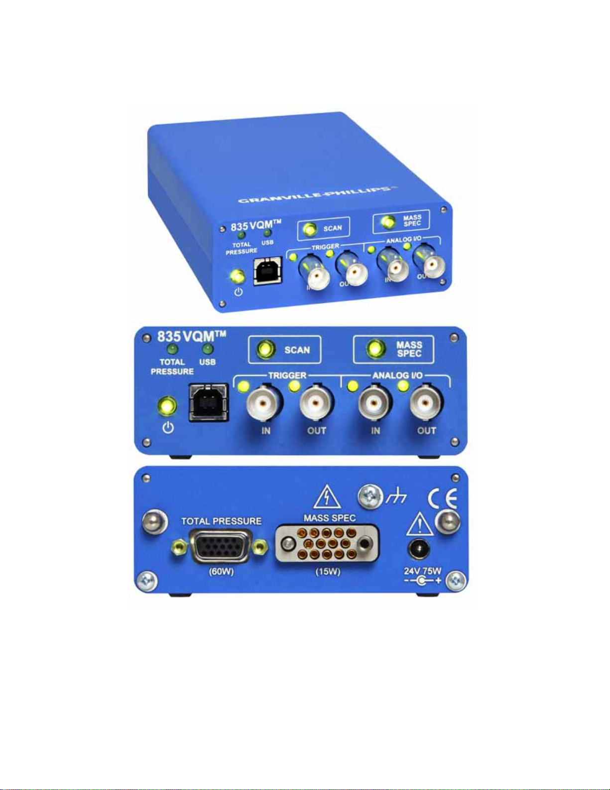
5.4 Front Panel Controls, Interconnects, and LEDs . . . . . . . . . . . . . . . . . . . . . . . . . . . . . . . . . . . . . . . . . . . . 56
5.4.1 Buttons. . . . . . . . . . . . . . . . . . . . . . . . . . . . . . . . . . . . . . . . . . . . . . . . . . . . . . . . . . . . . . . . . . . . . . 56
5.4.2 Power Button/LED . . . . . . . . . . . . . . . . . . . . . . . . . . . . . . . . . . . . . . . . . . . . . . . . . . . . . . . . . . . . 57
5.4.3 SCAN Button/LED . . . . . . . . . . . . . . . . . . . . . . . . . . . . . . . . . . . . . . . . . . . . . . . . . . . . . . . . . . . . 58
5.4.4 MASS SPEC Button/LED . . . . . . . . . . . . . . . . . . . . . . . . . . . . . . . . . . . . . . . . . . . . . . . . . . . . . . . 59
5.5 Front Panel Connectors . . . . . . . . . . . . . . . . . . . . . . . . . . . . . . . . . . . . . . . . . . . . . . . . . . . . . . . . . . . . . . . 62
5.5.1 Trigger IN BNC Connector / LED . . . . . . . . . . . . . . . . . . . . . . . . . . . . . . . . . . . . . . . . . . . . . . . . 62
5.5.2 Trigger OUT BNC Connector / LED . . . . . . . . . . . . . . . . . . . . . . . . . . . . . . . . . . . . . . . . . . . . . . 63
5.5.3 Analog IN BNC Connector / LED. . . . . . . . . . . . . . . . . . . . . . . . . . . . . . . . . . . . . . . . . . . . . . . . . 64
5.5.4 Analog OUT BNC Connector / LED . . . . . . . . . . . . . . . . . . . . . . . . . . . . . . . . . . . . . . . . . . . . . . 65
5.5.5 USB Port / LED. . . . . . . . . . . . . . . . . . . . . . . . . . . . . . . . . . . . . . . . . . . . . . . . . . . . . . . . . . . . . . . 65
5.5.6 External Total Pressure Connector / LED . . . . . . . . . . . . . . . . . . . . . . . . . . . . . . . . . . . . . . . . . . . 66
5.6 Rear Panel Controls and Interconnects . . . . . . . . . . . . . . . . . . . . . . . . . . . . . . . . . . . . . . . . . . . . . . . . . . . 67
5.6.1 TOTAL PRESSURE Connector . . . . . . . . . . . . . . . . . . . . . . . . . . . . . . . . . . . . . . . . . . . . . . . . . . 67
5.6.2 MASS SPEC Connector. . . . . . . . . . . . . . . . . . . . . . . . . . . . . . . . . . . . . . . . . . . . . . . . . . . . . . . . . 68
5.6.3 24 Vdc, 75 W Connector . . . . . . . . . . . . . . . . . . . . . . . . . . . . . . . . . . . . . . . . . . . . . . . . . . . . . . . . 68
5.6.4 Grounding Lug. . . . . . . . . . . . . . . . . . . . . . . . . . . . . . . . . . . . . . . . . . . . . . . . . . . . . . . . . . . . . . . . 69
5.7 MS Gauge Ion Trap Power Supply Settings . . . . . . . . . . . . . . . . . . . . . . . . . . . . . . . . . . . . . . . . . . . . . . . . 69
5.7.1 Filament Overpower Detection . . . . . . . . . . . . . . . . . . . . . . . . . . . . . . . . . . . . . . . . . . . . . . . . . . . 71
5.7.2 RF Signal Generator. . . . . . . . . . . . . . . . . . . . . . . . . . . . . . . . . . . . . . . . . . . . . . . . . . . . . . . . . . . . 71
5.7.3 Electrometer. . . . . . . . . . . . . . . . . . . . . . . . . . . . . . . . . . . . . . . . . . . . . . . . . . . . . . . . . . . . . . . . . . 73
5.8 Power Modes . . . . . . . . . . . . . . . . . . . . . . . . . . . . . . . . . . . . . . . . . . . . . . . . . . . . . . . . . . . . . . . . . . . . . . . 75
5.9 Power ON/OFF Sequence . . . . . . . . . . . . . . . . . . . . . . . . . . . . . . . . . . . . . . . . . . . . . . . . . . . . . . . . . . . . . 76
5.9.1 Power ON Sequence. . . . . . . . . . . . . . . . . . . . . . . . . . . . . . . . . . . . . . . . . . . . . . . . . . . . . . . . . . . . 76
5.9.2 Standby Power Sequence . . . . . . . . . . . . . . . . . . . . . . . . . . . . . . . . . . . . . . . . . . . . . . . . . . . . . . . . 77
5.9.3 Power-On Self-Test . . . . . . . . . . . . . . . . . . . . . . . . . . . . . . . . . . . . . . . . . . . . . . . . . . . . . . . . . . . . 77
5.10 Micro-Ion Gauge Operation . . . . . . . . . . . . . . . . . . . . . . . . . . . . . . . . . . . . . . . . . . . . . . . . . . . . . . . . . . . 78
5.10.1 Autopressure Mode. . . . . . . . . . . . . . . . . . . . . . . . . . . . . . . . . . . . . . . . . . . . . . . . . . . . . . . . . . . . 79
5.10.2 Overpressure Protection . . . . . . . . . . . . . . . . . . . . . . . . . . . . . . . . . . . . . . . . . . . . . . . . . . . . . . . . 80
Series 835 Vacuum Quality Monitor
Instruction Manual - 835000 - Rev. E
6

5.11 Mass Spectrometry Scan Control . . . . . . . . . . . . . . . . . . . . . . . . . . . . . . . . . . . . . . . . . . . . . . . . . . . . . . . . 81
5.11.1 Manual Scan Control . . . . . . . . . . . . . . . . . . . . . . . . . . . . . . . . . . . . . . . . . . . . . . . . . . . . . . . . . . 82
5.11.2 External Trigger Scan Control . . . . . . . . . . . . . . . . . . . . . . . . . . . . . . . . . . . . . . . . . . . . . . . . . . . 82
5.11.3 Remote Scan Control . . . . . . . . . . . . . . . . . . . . . . . . . . . . . . . . . . . . . . . . . . . . . . . . . . . . . . . . . . 82
5.11.4 Mass Spectrometry Scan Count . . . . . . . . . . . . . . . . . . . . . . . . . . . . . . . . . . . . . . . . . . . . . . . . . . 82
5.11.5 Single Scan . . . . . . . . . . . . . . . . . . . . . . . . . . . . . . . . . . . . . . . . . . . . . . . . . . . . . . . . . . . . . . . . . . 82
5.11.6 Continuous Scans. . . . . . . . . . . . . . . . . . . . . . . . . . . . . . . . . . . . . . . . . . . . . . . . . . . . . . . . . . . . . 83
5.12 Typical System Configurations . . . . . . . . . . . . . . . . . . . . . . . . . . . . . . . . . . . . . . . . . . . . . . . . . . . . . . . . . 83
5.12.1 Standard Setup . . . . . . . . . . . . . . . . . . . . . . . . . . . . . . . . . . . . . . . . . . . . . . . . . . . . . . . . . . . . . . . 83
5.12.2 Standard Setup with External Trigger Pulses . . . . . . . . . . . . . . . . . . . . . . . . . . . . . . . . . . . . . . . . 85
5.12.3 Stand Alone Setup . . . . . . . . . . . . . . . . . . . . . . . . . . . . . . . . . . . . . . . . . . . . . . . . . . . . . . . . . . . . 86
5.12.4 Stand Alone Setup with External Pulses . . . . . . . . . . . . . . . . . . . . . . . . . . . . . . . . . . . . . . . . . . . . 87
5.13 Timing Diagrams for MS Scan Control . . . . . . . . . . . . . . . . . . . . . . . . . . . . . . . . . . . . . . . . . . . . . . . . . . . 88
5.13.1 Immediate Trigger Mode . . . . . . . . . . . . . . . . . . . . . . . . . . . . . . . . . . . . . . . . . . . . . . . . . . . . . . . 88
5.13.2 Internal Trigger with No USB Data . . . . . . . . . . . . . . . . . . . . . . . . . . . . . . . . . . . . . . . . . . . . . . . 89
5.13.3 Internal Trigger with USB Data . . . . . . . . . . . . . . . . . . . . . . . . . . . . . . . . . . . . . . . . . . . . . . . . . . 90
5.13.4 Buffer Overwrite. . . . . . . . . . . . . . . . . . . . . . . . . . . . . . . . . . . . . . . . . . . . . . . . . . . . . . . . . . . . . . 90
Chapter 6 Ion Trap Mass Spectrometer Gauge . . . . . . . . . . . . . . . . . . . . . . . . . . . . . . . . . . . . . . . . . . . . . . . . . . . . 93
6.1 Introduction to the MS Gauge . . . . . . . . . . . . . . . . . . . . . . . . . . . . . . . . . . . . . . . . . . . . . . . . . . . . . . . . . 93
6.2 Terms used in this chapter . . . . . . . . . . . . . . . . . . . . . . . . . . . . . . . . . . . . . . . . . . . . . . . . . . . . . . . . . . . . . 93
6.3 MS Gauge Overview . . . . . . . . . . . . . . . . . . . . . . . . . . . . . . . . . . . . . . . . . . . . . . . . . . . . . . . . . . . . . . . . . 93
6.4 MS Gauge Principles of Operation . . . . . . . . . . . . . . . . . . . . . . . . . . . . . . . . . . . . . . . . . . . . . . . . . . . . . 100
6.5 Construction Materials . . . . . . . . . . . . . . . . . . . . . . . . . . . . . . . . . . . . . . . . . . . . . . . . . . . . . . . . . . . . . . 105
6.6 Ionizer . . . . . . . . . . . . . . . . . . . . . . . . . . . . . . . . . . . . . . . . . . . . . . . . . . . . . . . . . . . . . . . . . . . . . . . . . . . 106
6.7 Ion Trap Mass Separator . . . . . . . . . . . . . . . . . . . . . . . . . . . . . . . . . . . . . . . . . . . . . . . . . . . . . . . . . . . . . 108
6.8 Ion Detector Assembly . . . . . . . . . . . . . . . . . . . . . . . . . . . . . . . . . . . . . . . . . . . . . . . . . . . . . . . . . . . . . . 111
6.9 MS Gauge Advanced User Settings . . . . . . . . . . . . . . . . . . . . . . . . . . . . . . . . . . . . . . . . . . . . . . . . . . . . . 113
6.9.1 Electron Multiplier Bias . . . . . . . . . . . . . . . . . . . . . . . . . . . . . . . . . . . . . . . . . . . . . . . . . . . . . . . . 116
6.9.2 RF Amplitude Peak-to-Peak . . . . . . . . . . . . . . . . . . . . . . . . . . . . . . . . . . . . . . . . . . . . . . . . . . . . . 116
6.9.3 Filament Emission . . . . . . . . . . . . . . . . . . . . . . . . . . . . . . . . . . . . . . . . . . . . . . . . . . . . . . . . . . . . 118
6.9.4 Repeller Plate Bias . . . . . . . . . . . . . . . . . . . . . . . . . . . . . . . . . . . . . . . . . . . . . . . . . . . . . . . . . . . . 119
6.9.5 Exit Plate Bias. . . . . . . . . . . . . . . . . . . . . . . . . . . . . . . . . . . . . . . . . . . . . . . . . . . . . . . . . . . . . . . . 120
6.9.6 Electron Multiplier Shield Bias. . . . . . . . . . . . . . . . . . . . . . . . . . . . . . . . . . . . . . . . . . . . . . . . . . . 120
6.9.7 Filament Bias . . . . . . . . . . . . . . . . . . . . . . . . . . . . . . . . . . . . . . . . . . . . . . . . . . . . . . . . . . . . . . . . 121
6.9.8 Entry Plate Bias . . . . . . . . . . . . . . . . . . . . . . . . . . . . . . . . . . . . . . . . . . . . . . . . . . . . . . . . . . . . . . 121
6.9.9 Pressure Plate Bias . . . . . . . . . . . . . . . . . . . . . . . . . . . . . . . . . . . . . . . . . . . . . . . . . . . . . . . . . . . . 121
6.9.10 Cup Bias. . . . . . . . . . . . . . . . . . . . . . . . . . . . . . . . . . . . . . . . . . . . . . . . . . . . . . . . . . . . . . . . . . . 121
6.9.11 Transition Bias . . . . . . . . . . . . . . . . . . . . . . . . . . . . . . . . . . . . . . . . . . . . . . . . . . . . . . . . . . . . . . 122
6.10 Superharmonics . . . . . . . . . . . . . . . . . . . . . . . . . . . . . . . . . . . . . . . . . . . . . . . . . . . . . . . . . . . . . . . . . . . . 122
Chapter 7 MS Gauge Maintenance . . . . . . . . . . . . . . . . . . . . . . . . . . . . . . . . . . . . . . . . . . . . . . . . . . . . . . . . . . . . 125
7.1 Introduction . . . . . . . . . . . . . . . . . . . . . . . . . . . . . . . . . . . . . . . . . . . . . . . . . . . . . . . . . . . . . . . . . . . . . . 125
7.2 Unpacking, Handling, and Long-Term Storage . . . . . . . . . . . . . . . . . . . . . . . . . . . . . . . . . . . . . . . . . . . . 125
7.2.1 Storage Recommendations . . . . . . . . . . . . . . . . . . . . . . . . . . . . . . . . . . . . . . . . . . . . . . . . . . . . . . 125
7.3 Bakeout Procedure . . . . . . . . . . . . . . . . . . . . . . . . . . . . . . . . . . . . . . . . . . . . . . . . . . . . . . . . . . . . . . . . . . 126
7.4 Environmental Requirements . . . . . . . . . . . . . . . . . . . . . . . . . . . . . . . . . . . . . . . . . . . . . . . . . . . . . . . . . 128
7.4.1 Pressure Ranges . . . . . . . . . . . . . . . . . . . . . . . . . . . . . . . . . . . . . . . . . . . . . . . . . . . . . . . . . . . . . . 128
7.4.2 Temperature Range . . . . . . . . . . . . . . . . . . . . . . . . . . . . . . . . . . . . . . . . . . . . . . . . . . . . . . . . . . . 128
7.4.3 Humidity Range. . . . . . . . . . . . . . . . . . . . . . . . . . . . . . . . . . . . . . . . . . . . . . . . . . . . . . . . . . . . . . 129
7.4.4 Warm-up Periods . . . . . . . . . . . . . . . . . . . . . . . . . . . . . . . . . . . . . . . . . . . . . . . . . . . . . . . . . . . . 129
Series 835 Vacuum Quality Monitor
Instruction Manual - 835000 - Rev. E
7

Table of Contents
7.5 Filament Assembly . . . . . . . . . . . . . . . . . . . . . . . . . . . . . . . . . . . . . . . . . . . . . . . . . . . . . . . . . . . . . . . . . . 130
7.6 Electron Multiplier Detector . . . . . . . . . . . . . . . . . . . . . . . . . . . . . . . . . . . . . . . . . . . . . . . . . . . . . . . . . . 135
7.7 Cleaning a VQM Gauge . . . . . . . . . . . . . . . . . . . . . . . . . . . . . . . . . . . . . . . . . . . . . . . . . . . . . . . . . . . . . 142
Chapter 8 Initial Operation & Viewer Software . . . . . . . . . . . . . . . . . . . . . . . . . . . . . . . . . . . . . . . . . . . . . . . . . . 143
8.1 VQM® Viewer Application Software for the VQM System . . . . . . . . . . . . . . . . . . . . . . . . . . . . . . . . . . 143
8.2 VQM Viewer Application Icons and Screen Displays . . . . . . . . . . . . . . . . . . . . . . . . . . . . . . . . . . . . . . . 144
8.3 Initial Operation Procedure . . . . . . . . . . . . . . . . . . . . . . . . . . . . . . . . . . . . . . . . . . . . . . . . . . . . . . . . . . . 148
8.4 Using the Viewer Application . . . . . . . . . . . . . . . . . . . . . . . . . . . . . . . . . . . . . . . . . . . . . . . . . . . . . . . . . 160
8.5 Troubleshooting . . . . . . . . . . . . . . . . . . . . . . . . . . . . . . . . . . . . . . . . . . . . . . . . . . . . . . . . . . . . . . . . . . . 191
7.5.1 Introduction. . . . . . . . . . . . . . . . . . . . . . . . . . . . . . . . . . . . . . . . . . . . . . . . . . . . . . . . . . . . . . . . . 130
7.5.2 Filament Assembly Replacement. . . . . . . . . . . . . . . . . . . . . . . . . . . . . . . . . . . . . . . . . . . . . . . . . . 130
7.5.3 Repeller Voltage Optimization . . . . . . . . . . . . . . . . . . . . . . . . . . . . . . . . . . . . . . . . . . . . . . . . . . . 134
7.5.4 Filament Operation . . . . . . . . . . . . . . . . . . . . . . . . . . . . . . . . . . . . . . . . . . . . . . . . . . . . . . . . . . . 135
7.6.1 Introduction. . . . . . . . . . . . . . . . . . . . . . . . . . . . . . . . . . . . . . . . . . . . . . . . . . . . . . . . . . . . . . . . . 135
7.6.2 Best-Known Practices . . . . . . . . . . . . . . . . . . . . . . . . . . . . . . . . . . . . . . . . . . . . . . . . . . . . . . . . . . 135
7.6.3 Operating Pressure . . . . . . . . . . . . . . . . . . . . . . . . . . . . . . . . . . . . . . . . . . . . . . . . . . . . . . . . . . . . 136
7.6.4 Operating Temperature . . . . . . . . . . . . . . . . . . . . . . . . . . . . . . . . . . . . . . . . . . . . . . . . . . . . . . . . 136
7.6.5 Bakeout Temperature. . . . . . . . . . . . . . . . . . . . . . . . . . . . . . . . . . . . . . . . . . . . . . . . . . . . . . . . . . 136
7.6.6 Operating Voltage . . . . . . . . . . . . . . . . . . . . . . . . . . . . . . . . . . . . . . . . . . . . . . . . . . . . . . . . . . . . 137
7.6.7 Contamination. . . . . . . . . . . . . . . . . . . . . . . . . . . . . . . . . . . . . . . . . . . . . . . . . . . . . . . . . . . . . . . 137
7.6.8 Initial Operation. . . . . . . . . . . . . . . . . . . . . . . . . . . . . . . . . . . . . . . . . . . . . . . . . . . . . . . . . . . . . . 137
7.6.9 Gain Adjustment . . . . . . . . . . . . . . . . . . . . . . . . . . . . . . . . . . . . . . . . . . . . . . . . . . . . . . . . . . . . . 138
7.6.10 Electron Multiplier Replacement . . . . . . . . . . . . . . . . . . . . . . . . . . . . . . . . . . . . . . . . . . . . . . . . 138
8.1.1 Software VIs, Services, and Driver . . . . . . . . . . . . . . . . . . . . . . . . . . . . . . . . . . . . . . . . . . . . . . . . 144
8.2.1 Viewer Application Icons . . . . . . . . . . . . . . . . . . . . . . . . . . . . . . . . . . . . . . . . . . . . . . . . . . . . . . . 145
8.3.1 Connect the USB Cable . . . . . . . . . . . . . . . . . . . . . . . . . . . . . . . . . . . . . . . . . . . . . . . . . . . . . . . . 148
8.3.2 Initial Pump Down . . . . . . . . . . . . . . . . . . . . . . . . . . . . . . . . . . . . . . . . . . . . . . . . . . . . . . . . . . . 149
8.3.3 Abbreviated Initial Startup/Setup Procedure. . . . . . . . . . . . . . . . . . . . . . . . . . . . . . . . . . . . . . . . . 150
8.3.4 Filament Outgassing. . . . . . . . . . . . . . . . . . . . . . . . . . . . . . . . . . . . . . . . . . . . . . . . . . . . . . . . . . . 153
8.3.5 Electron Multiplier Preconditioning. . . . . . . . . . . . . . . . . . . . . . . . . . . . . . . . . . . . . . . . . . . . . . . 154
8.3.6 Auto Tune . . . . . . . . . . . . . . . . . . . . . . . . . . . . . . . . . . . . . . . . . . . . . . . . . . . . . . . . . . . . . . . . . . 155
8.3.7 Manual Electron Multiplier Bias Voltage Adjustment (optional) . . . . . . . . . . . . . . . . . . . . . . . . . 156
8.3.8 Mass Axis Calibration. . . . . . . . . . . . . . . . . . . . . . . . . . . . . . . . . . . . . . . . . . . . . . . . . . . . . . . . . . 158
8.3.9 Storing the Gauge Settings . . . . . . . . . . . . . . . . . . . . . . . . . . . . . . . . . . . . . . . . . . . . . . . . . . . . . . 159
8.4.1 Connect . . . . . . . . . . . . . . . . . . . . . . . . . . . . . . . . . . . . . . . . . . . . . . . . . . . . . . . . . . . . . . . . . . . 160
8.4.2 Gauge Operating Mode . . . . . . . . . . . . . . . . . . . . . . . . . . . . . . . . . . . . . . . . . . . . . . . . . . . . . . . 162
8.4.3 Auto Tune . . . . . . . . . . . . . . . . . . . . . . . . . . . . . . . . . . . . . . . . . . . . . . . . . . . . . . . . . . . . . . . . . 164
8.4.4 Summary . . . . . . . . . . . . . . . . . . . . . . . . . . . . . . . . . . . . . . . . . . . . . . . . . . . . . . . . . . . . . . . . . . 166
8.4.5 Trend . . . . . . . . . . . . . . . . . . . . . . . . . . . . . . . . . . . . . . . . . . . . . . . . . . . . . . . . . . . . . . . . . . . . . 171
8.4.6 Leak . . . . . . . . . . . . . . . . . . . . . . . . . . . . . . . . . . . . . . . . . . . . . . . . . . . . . . . . . . . . . . . . . . . . . . 172
8.4.7 Settings (preferences) . . . . . . . . . . . . . . . . . . . . . . . . . . . . . . . . . . . . . . . . . . . . . . . . . . . . . . . . . 175
8.4.8 Tune . . . . . . . . . . . . . . . . . . . . . . . . . . . . . . . . . . . . . . . . . . . . . . . . . . . . . . . . . . . . . . . . . . . . . . 178
8.4.9 Log Data . . . . . . . . . . . . . . . . . . . . . . . . . . . . . . . . . . . . . . . . . . . . . . . . . . . . . . . . . . . . . . . . . . 184
8.4.10 Save . . . . . . . . . . . . . . . . . . . . . . . . . . . . . . . . . . . . . . . . . . . . . . . . . . . . . . . . . . . . . . . . . . . . . 186
8.4.11 VQI
TM
(Vacuum Quality IndexTM) . . . . . . . . . . . . . . . . . . . . . . . . . . . . . . . . . . . . . . . . . . . . . . . 187
8.4.12 VQI Status . . . . . . . . . . . . . . . . . . . . . . . . . . . . . . . . . . . . . . . . . . . . . . . . . . . . . . . . . . . . . . . . . 189
8.4.13 Status/Error Reporting and Contextual Help . . . . . . . . . . . . . . . . . . . . . . . . . . . . . . . . . . . . . . . 189
8.5.1 Viewer Application Does Not Open. . . . . . . . . . . . . . . . . . . . . . . . . . . . . . . . . . . . . . . . . . . . . . . 191
8.5.2 Viewer Application Does Not List Any VQM Controllers . . . . . . . . . . . . . . . . . . . . . . . . . . . . . . 191
8.5.3 Viewer Application Does Not Connect to a Listed Controller or No Valid Connections Error (5027)
8
Series 835 Vacuum Quality Monitor
Instruction Manual - 835000 - Rev. E

191
8.5.4 Service is not responding . . . . . . . . . . . . . . . . . . . . . . . . . . . . . . . . . . . . . . . . . . . . . . . . . . . . . . . 191
8.5.5 .Net Error when attempting to connect Viewer Application to controller. . . . . . . . . . . . . . . . . . . 191
8.5.6 Viewer Application displays 'Generic Error 42" or "Error 74" when connect to a controller. . . . . 191
8.5.7 Auto Tune Failures. . . . . . . . . . . . . . . . . . . . . . . . . . . . . . . . . . . . . . . . . . . . . . . . . . . . . . . . . . . . 191
8.5.8 390 Checksum Error . . . . . . . . . . . . . . . . . . . . . . . . . . . . . . . . . . . . . . . . . . . . . . . . . . . . . . . . . . 192
8.5.9 Timeouts, etc.. . . . . . . . . . . . . . . . . . . . . . . . . . . . . . . . . . . . . . . . . . . . . . . . . . . . . . . . . . . . . . . . 192
8.5.10 Where are the Logs? . . . . . . . . . . . . . . . . . . . . . . . . . . . . . . . . . . . . . . . . . . . . . . . . . . . . . . . . . . 193
Chapter 9 835 VQM® Command Set . . . . . . . . . . . . . . . . . . . . . . . . . . . . . . . . . . . . . . . . . . . . . . . . . . . . . . . . . 195
9.1 Introduction . . . . . . . . . . . . . . . . . . . . . . . . . . . . . . . . . . . . . . . . . . . . . . . . . . . . . . . . . . . . . . . . . . . . . . 195
9.1.1 USB Driver Installation . . . . . . . . . . . . . . . . . . . . . . . . . . . . . . . . . . . . . . . . . . . . . . . . . . . . . . . . 195
9.1.2 Logical Instruments . . . . . . . . . . . . . . . . . . . . . . . . . . . . . . . . . . . . . . . . . . . . . . . . . . . . . . . . . . . 195
9.1.3 Command Format . . . . . . . . . . . . . . . . . . . . . . . . . . . . . . . . . . . . . . . . . . . . . . . . . . . . . . . . . . . . 197
9.2 SCPI Command Tables . . . . . . . . . . . . . . . . . . . . . . . . . . . . . . . . . . . . . . . . . . . . . . . . . . . . . . . . . . . . . . 198
9.2.1 Input Format . . . . . . . . . . . . . . . . . . . . . . . . . . . . . . . . . . . . . . . . . . . . . . . . . . . . . . . . . . . . . . . . 198
9.2.2 Response Format . . . . . . . . . . . . . . . . . . . . . . . . . . . . . . . . . . . . . . . . . . . . . . . . . . . . . . . . . . . . . 198
9.3 IEEE 488.2 Required Commands . . . . . . . . . . . . . . . . . . . . . . . . . . . . . . . . . . . . . . . . . . . . . . . . . . . . . . 200
9.3.1 CALibration Subsystem . . . . . . . . . . . . . . . . . . . . . . . . . . . . . . . . . . . . . . . . . . . . . . . . . . . . . . . . 201
9.3.2 CONFigure Subsystem. . . . . . . . . . . . . . . . . . . . . . . . . . . . . . . . . . . . . . . . . . . . . . . . . . . . . . . . . 201
9.3.3 FETCh Subsystem . . . . . . . . . . . . . . . . . . . . . . . . . . . . . . . . . . . . . . . . . . . . . . . . . . . . . . . . . . . . 202
9.3.4 FORMat Subsystem . . . . . . . . . . . . . . . . . . . . . . . . . . . . . . . . . . . . . . . . . . . . . . . . . . . . . . . . . . . 202
9.3.5 INPut Subsystem . . . . . . . . . . . . . . . . . . . . . . . . . . . . . . . . . . . . . . . . . . . . . . . . . . . . . . . . . . . . . 203
9.3.6 INSTrument Subsystem . . . . . . . . . . . . . . . . . . . . . . . . . . . . . . . . . . . . . . . . . . . . . . . . . . . . . . . . 204
9.3.7 MEASure Subsystem . . . . . . . . . . . . . . . . . . . . . . . . . . . . . . . . . . . . . . . . . . . . . . . . . . . . . . . . . . 205
9.3.8 MEMory Subsystem. . . . . . . . . . . . . . . . . . . . . . . . . . . . . . . . . . . . . . . . . . . . . . . . . . . . . . . . . . . 206
9.3.9 OUTPut Subsystem . . . . . . . . . . . . . . . . . . . . . . . . . . . . . . . . . . . . . . . . . . . . . . . . . . . . . . . . . . . 207
9.3.10 SENSe Subsystem. . . . . . . . . . . . . . . . . . . . . . . . . . . . . . . . . . . . . . . . . . . . . . . . . . . . . . . . . . . . 208
9.3.11 SOURce Subsystem . . . . . . . . . . . . . . . . . . . . . . . . . . . . . . . . . . . . . . . . . . . . . . . . . . . . . . . . . . 208
9.3.12 STATus Subsystem. . . . . . . . . . . . . . . . . . . . . . . . . . . . . . . . . . . . . . . . . . . . . . . . . . . . . . . . . . . 210
9.3.13 SYSTem Subsystem . . . . . . . . . . . . . . . . . . . . . . . . . . . . . . . . . . . . . . . . . . . . . . . . . . . . . . . . . . 220
9.3.14 TEST Subsystem . . . . . . . . . . . . . . . . . . . . . . . . . . . . . . . . . . . . . . . . . . . . . . . . . . . . . . . . . . . . 221
9.4 Test Report . . . . . . . . . . . . . . . . . . . . . . . . . . . . . . . . . . . . . . . . . . . . . . . . . . . . . . . . . . . . . . . . . . . . . . . 222
9.4.1 TRIGger Subsystem . . . . . . . . . . . . . . . . . . . . . . . . . . . . . . . . . . . . . . . . . . . . . . . . . . . . . . . . . . . 223
9.4.2 Reset State . . . . . . . . . . . . . . . . . . . . . . . . . . . . . . . . . . . . . . . . . . . . . . . . . . . . . . . . . . . . . . . . . . 224
9.4.3 Error/Event Codes . . . . . . . . . . . . . . . . . . . . . . . . . . . . . . . . . . . . . . . . . . . . . . . . . . . . . . . . . . . . 225
9.4.4 Data Interchange Format . . . . . . . . . . . . . . . . . . . . . . . . . . . . . . . . . . . . . . . . . . . . . . . . . . . . . . . 231
9.5 Simplified Programming Overview and Examples . . . . . . . . . . . . . . . . . . . . . . . . . . . . . . . . . . . . . . . . . . 236
9.5.1 Bias Voltages . . . . . . . . . . . . . . . . . . . . . . . . . . . . . . . . . . . . . . . . . . . . . . . . . . . . . . . . . . . . . . . . 236
9.5.2 Filament Power . . . . . . . . . . . . . . . . . . . . . . . . . . . . . . . . . . . . . . . . . . . . . . . . . . . . . . . . . . . . . . 237
9.5.3 Emission Current and Filament Bias Voltage . . . . . . . . . . . . . . . . . . . . . . . . . . . . . . . . . . . . . . . . 237
9.5.4 Formatting Fetch data . . . . . . . . . . . . . . . . . . . . . . . . . . . . . . . . . . . . . . . . . . . . . . . . . . . . . . . . . 237
9.5.5 Partial Pressure Measurement . . . . . . . . . . . . . . . . . . . . . . . . . . . . . . . . . . . . . . . . . . . . . . . . . . . . 239
9.5.6 External Total Pressure. . . . . . . . . . . . . . . . . . . . . . . . . . . . . . . . . . . . . . . . . . . . . . . . . . . . . . . . . 240
9.5.7 Store/Load Ion Trap and Controller Settings . . . . . . . . . . . . . . . . . . . . . . . . . . . . . . . . . . . . . . . . 240
9.5.8 Change or Calibrate Electrometer Gain/Sensitivity. . . . . . . . . . . . . . . . . . . . . . . . . . . . . . . . . . . . 241
9.5.9 Real-Time Clock . . . . . . . . . . . . . . . . . . . . . . . . . . . . . . . . . . . . . . . . . . . . . . . . . . . . . . . . . . . . . 241
9.5.10 Manual Control of the Digital Output on the BNC. . . . . . . . . . . . . . . . . . . . . . . . . . . . . . . . . . 241
9.5.11 Fatal Errors. . . . . . . . . . . . . . . . . . . . . . . . . . . . . . . . . . . . . . . . . . . . . . . . . . . . . . . . . . . . . . . . . 241
9.5.12 Reading Controller Status/Clearing Status Registers . . . . . . . . . . . . . . . . . . . . . . . . . . . . . . . . . . 242
9.6 Using a Terminal to Communicate with the VQM System . . . . . . . . . . . . . . . . . . . . . . . . . . . . . . . . . . . 242
9.6.1 Using HyperTerminal . . . . . . . . . . . . . . . . . . . . . . . . . . . . . . . . . . . . . . . . . . . . . . . . . . . . . . . . . 244
Series 835 Vacuum Quality Monitor
Instruction Manual - 835000 - Rev. E
9

Table of Contents
Chapter 10 Service & Maintenance . . . . . . . . . . . . . . . . . . . . . . . . . . . . . . . . . . . . . . . . . . . . . . . . . . . . . . . . . . . . 247
10.1 Service Guidelines . . . . . . . . . . . . . . . . . . . . . . . . . . . . . . . . . . . . . . . . . . . . . . . . . . . . . . . . . . . . . . . . . . 247
10.2 Damage Requiring Service . . . . . . . . . . . . . . . . . . . . . . . . . . . . . . . . . . . . . . . . . . . . . . . . . . . . . . . . . . . . 247
10.3 General Repair Guidelines . . . . . . . . . . . . . . . . . . . . . . . . . . . . . . . . . . . . . . . . . . . . . . . . . . . . . . . . . . . . 248
10.4 MS Gauge Repair . . . . . . . . . . . . . . . . . . . . . . . . . . . . . . . . . . . . . . . . . . . . . . . . . . . . . . . . . . . . . . . . . . 248
Chapter 11 Index . . . . . . . . . . . . . . . . . . . . . . . . . . . . . . . . . . . . . . . . . . . . . . . . . . . . . . . . . . . . . . . . . . . . . . . . . . 249
10
Series 835 Vacuum Quality Monitor
Instruction Manual - 835000 - Rev. E
Chapter 1
1 Safety Instructions
1.1 Safety Introduction
BEGIN BY READING THESE IMPORTANT SAFETY INSTRUCTIONS AND NOTES.
Additional safety notices and information is provided at appropriate points throughout this
instruction manual.
These safety alert symbols in this manual or on the rear panel of the
Product mean caution − personal safety, property damage or danger
from electric shock. Read these instructions carefully.
Throughout this instruction manual the word “product” refers to the Series 835 Vacuum Quality
®
Monitor (VQM
This product is designed and tested to offer reasonably safe service provided it is installed, operated, and serviced in strict
accordance with these safety instructions.
) and all of its approved parts and accessories.
NOTE: These instructions do not and cannot provide for every contingency
that may arise in connection with the installation, operation, or maintenance
of this product. If you require further assistance, contact Brooks Automation,
Inc. at the address on the page 3 and Section 1.5 of this manual.
Failure to comply with these instructions may result in serious personal injury,
including death, or property damage.
These safety precautions must be observed during all phases of operation, installation, and service
of this product. Failure to comply with these precautions or with specific warnings elsewhere in this
manual violates safety standards of design, manufacture, and intended use of the instrument.
Brooks Automation, Inc. disclaims all liability for the customer's failure to comply with these
requirements.
The service and repair information in this manual is for the use of Qualified Service
Personnel. To avoid electrical shock or personal injury, do not perform any
procedures in this manual or perform any servicing on this product unless you are
qualified to do so.
• Read Instructions – Read all safety and operating instructions before operating the product.
• Retain Instructions – Retain the Safety and Operating Instructions for future reference.
• Heed Warnings – Adhere to all warnings on the product and in the operating instructions.
• Follow Instructions – Follow all operating and maintenance instructions.
• Accessories – Do not use accessories not recommended in this manual as they may be hazardous.
Series 835 Vacuum Quality Monitor
Instruction Manual - 835000 - Rev. E
11
1 Safety Instructions
To reduce the risk of fire or electric shock, do not expose this product to rain or
moisture.
Objects and Liquid Entry − Never push objects of any kind into this product
through openings as they may touch dangerous voltage points or short out parts that
could result in a fire or electric shock. Be careful not to spill liquid of any kind onto
the products.
Do not substitute parts or modify the instrument.
Because of the danger of introducing additional hazards, do not install substitute
parts or perform any unauthorized modification to the product. Return the product
to a service facility designated by Brooks Automation, Inc. for service and repair to
ensure that safety features are maintained. Do not use this product if it has
unauthorized modifications.
Replacement Parts − When replacement parts are required, be certain to use the
replacement parts that are specified by Brooks Automation, Inc. or that have the
same characteristics as the original parts. Unauthorized substitutions may result in
fire, electric shock or other hazards.
Safety Check − Upon completion of any service or repairs to this product, ask the
Qualified Service Person to perform safety checks to determine that the product is in
safe operating order.
Finite Lifetime − After ten years of normal use or even non−use, the electrical
insulation in this product may become less effective at preventing electrical shock.
Under certain environmental conditions which are beyond the manufacturer’s
control, some insulation material may deteriorate sooner. Therefore, periodically
inspect all electrical insulation for cracks, chafing, or other signs of deterioration.
Do not use if the electrical insulation has become unsafe.
Be aware that when high voltage is present in any vacuum system, a life threatening
electrical shock hazard may exist unless all exposed conductors are maintained at
Earth ground.
This hazard is not unique to this product.
Be aware that an electrical discharge through a gas may couple dangerous high
voltage directly to an ungrounded conductor almost as effectively as would a copper
wire connection. A person may be seriously injured or even killed by merely
touching an exposed ungrounded conductor at high potential.
This hazard is not unique to this product.
It is the user's responsibility to ensure that the automatic signals provided by the
product are always used in a safe manner. Carefully check the system programming
before switching to automatic operation.
12
Series 835 Vacuum Quality Monitor
Instruction Manual - 835000 - Rev. E
1.2 Equipment Grounding
Proper Grounding
All components of a vacuum system used with this or any similar high voltage
product must be maintained at Earth ground for safe operation. The power cord of
this product MUST be connected only to a properly grounded outlet. Be aware,
however, that grounding this product does not guarantee that other components of
the vacuum system are maintained at Earth ground. Have a licensed electrician
check the entire system to assure proper and safe grounding of all electrical
components.
Complying with the usual warning to connect the power cable only to a properly
grounded outlet is necessary but not sufficient for safe operation of a vacuum system
with this or any similar high voltage producing product.
Verify that the vacuum port to which the MS Gauge and all vacuum gauges are
mounted are electrically grounded. It is essential for personnel safety as well as
proper operation that the envelope of the gauge be connected to a facility ground. Use
a ground lug on a flange bolt if necessary.
NOTE: All components of the Vacuum System MUST be properly grounded.
See Section 3.8 and Figure 3−15 on page 43.
1 Safety Instructions
1.3 Implosion / Explosion
Install suitable devices that will limit the pressure to the level that the vacuum
system can safely withstand. In addition, install suitable pressure relief valves or
rupture disks that will release pressure at a level considerably below the pressure
that the system can safely withstand.
Danger of injury to personnel and damage to equipment exists on all vacuum systems that
incorporate gas sources or involve processes capable of pressurizing the system above the limits it
can safely withstand.
For example, danger of explosion in a vacuum system exists during backfilling from pressurized gas
cylinders because many vacuum devices such as ionization gauge tubes, glass windows, glass bell
jars, etc., are not designed to be pressurized.
Install suitable devices that will limit the pressure from external gas sources to the level that the
vacuum system can safely withstand. In addition, install suitable pressure relief valves or rupture
disks that will release pressure at a level considerably below that pressure which the system can
safely withstand.
Suppliers of pressure relief valves and pressure relief disks can be located via an internet search,
and are listed in the Thomas Register under “Valves, Relief” and “Discs, Rupture.”
Series 835 Vacuum Quality Monitor
Instruction Manual - 835000 - Rev. E
13
1 Safety Instructions
Confirm that these safety devices are properly installed before installing the product. In addition,
check that:
a. The proper gas cylinders are installed,
b. Gas cylinder valve positions are correct on manual systems, and
c. The automation is correct on automated gas delivery systems.
Do not operate in an explosive atmosphere.
Do not operate the product in the presence of flammable gases or fumes.
Operation of any electrical instrument in such an environment constitutes a definite
safety hazard.
Do not use the product to measure the pressure of explosive or combustible gases or
gas mixtures. Danger of explosion or inadvertent venting to atmosphere exists on all
vacuum systems which incorporate gas sources or involve processes capable of
pressurizing the system above safe limits.
It is the installer's responsibility to ensure that the automatic signals provided by the product are
always used in a safe manner. Carefully check manual operation of the system and the set point
programming before switching to automatic operation.
Where an equipment malfunction could cause a hazardous situation, always provide for fail-safe
operation. As an example, in an automatic backfill operation where a malfunction might cause high
internal pressures, provide an appropriate pressure relief device.
14
Series 835 Vacuum Quality Monitor
Instruction Manual - 835000 - Rev. E

1 Safety Instructions
1.4 Damage Requiring Service
Disconnect the product from all power sources and refer servicing to Qualified Service Personnel
under the following conditions:
a. When any cable or plug is damaged.
b. If any liquid has been spilled onto, or objects have fallen into the product.
c. If the product has been exposed to rain or water.
d. If the product does not operate normally even if you follow the operating instructions. Adjust
only those controls that are covered by the operation instructions. Improper adjustment of other
controls may result in damage and will often require extensive work by a qualified technician
to restore the product to its normal operation.
e. If the product has been dropped or the enclosure has been damaged.
f. If the product exhibits a distinct change in performance, service may be required.
1.5 Service Guidelines
Some minor problems are readily corrected on site. If the product requires service, please contact
our Customer Service Department at 303-652-4400 for troubleshooting help over the phone.
If a product must be returned to the factory for service, request a Return Material Authorization
(RMA) from Brooks Automation / Granville-Phillips. Do not return products without first obtaining
an RMA.
For vacuum gauges (including the VQM Ion Trap Mass Spectrometer Gauge), a hazardous materials
document may be required. The Brooks Automation / Granville-Phillips Customer Service
Representative will advise you regarding the required hazardous materials document and
procedures.
When returning equipment to Brooks Automation / Granville-Phillips, be sure to package the
products to prevent shipping damage. Circuit boards and modules separated from the VQM
Controller chassis must be handled using proper anti-static protection methods and must be
packaged in anti-static packaging. Brooks Automation / Granville-Phillips will supply return
packaging materials at no charge upon request. Shipping damage on returned products as a result of
inadequate packaging is the Buyer's responsibility. Before you return products to the factory, obtain
an RMA number by contacting Granville-Phillips customer service:
• Phone 1-303-652-4400 or 1-800-776-6543 within the USA, 8 AM to 5 PM Mountain Time Zone,
weekdays excluding holidays.
• Phone 1-800-367-4887 within the USA, 24 hours per day, seven days per week.
• Email co-csr@brooks.com
• For Global Customer Support, go to www.brooks.com and click on Services to locate the Brooks
Automation office nearest you.
Series 835 Vacuum Quality Monitor
Instruction Manual - 835000 - Rev. E
15

1 Safety Instructions
1.6 FCC Verification
This equipment has been tested and found to comply with the limits for a Class A digital device,
pursuant to Part 15 of the FCC Rules. These limits are designed to provide reasonable protection
against harmful interference when the equipment is operated in a commercial environment. This
equipment generates, uses, and can radiate radio frequency energy and, if not installed and used in
accordance with this instruction manual, may cause harmful interference to radio communications.
However, there is no guarantee that interference will not occur in a particular installation.
Operation of this equipment in a residential area is likely to cause harmful interference in which
case the user will be required to correct the interference at his own expense. If this equipment does
cause harmful interference to radio or television reception, which can be determined by turning the
equipment off and on, the user is encouraged to try to correct the interference by one or more of the
following measures:
• Reorient or relocate the receiving antenna.
• Increase the separation between the equipment and the receiver.
• Connect the equipment into an outlet on a circuit different from that to which the receiver is
connected.
16
Series 835 Vacuum Quality Monitor
Instruction Manual - 835000 - Rev. E
2 Introduction & Specifications
Chapter 2
2 Introduction & Specifications
2.1 General Description
The Vacuum Quality Monitor (VQM®) by Granville-Phillips combines the highest performance gas
analysis technology with outstanding instrumentation functional design that transforms complex
measurement into actionable information. The VQM System is the world's fastest, lowest power, gas
compositional analysis instrument with full data collection, spectral decomposition, and data
logging over the full 1-300 amu measurement range.
The VQM System is a mass spectrometer consisting of an Autoresonant Ion Trap Mass Spectrometry
(ART MS) Gauge (hereafter referred to as the MS Gauge), the VQM Controller, an interconnnect
cable, a communications interface for user-application development, and a VQM Viewer Software
application. The MS Gauge mounts directly onto any standard 2.75" ConFlat port of a vacuum
chamber. All of the internal components of the MS Gauge reside in the vacuum space where the gas
analysis measurements are performed.
The VQM Viewer Software application provides most of the functionality required to operate the
system. In addition, a high-level VQM Command Set, along with a serial USB interface port
provides full control of the VQM System from a Windows-based host PC.
A full-range total pressure measurement kit (the Micro-Ion ATM vacuum gauge module - see Figure
2-3) is available from Granville-Phillips to provide vacuum system pressure readouts and process
control functions, absolute partial pressure measurements, and mass spectrometer gauge
overpressure protection.
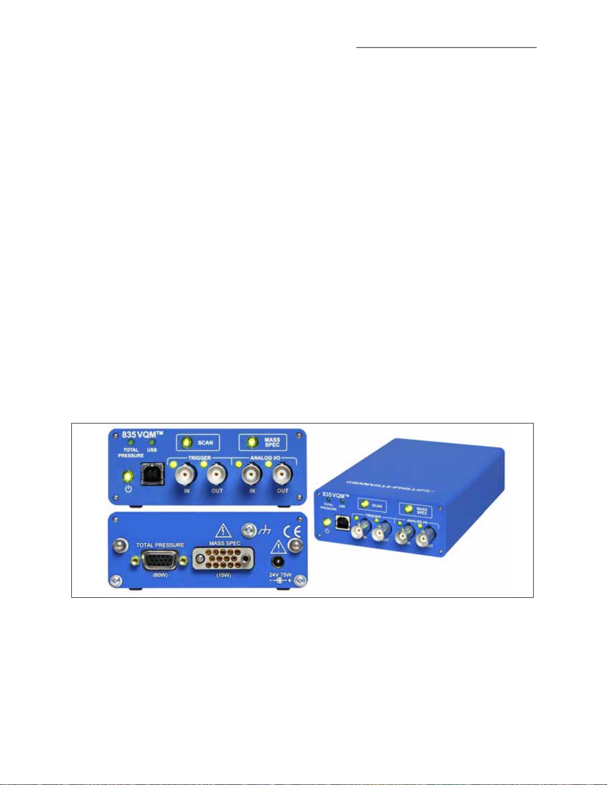
Figure 2-1 VQM Controller Front and Rear Panels
Series 835 Vacuum Quality Monitor
Instruction Manual - 835000 - Rev. E
17
2 Introduction & Specifications
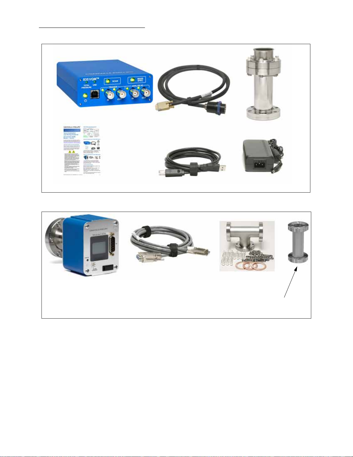
VQM Controller
VQM Ion Trap
Mass Spectrometer Gauge
Interconnect Cable - Controller
to Mass Spectrometer Gauge
Quick Installation
and Startup Guide
AC to 24 Vdc
Power Supply
USB Interconnect Cable
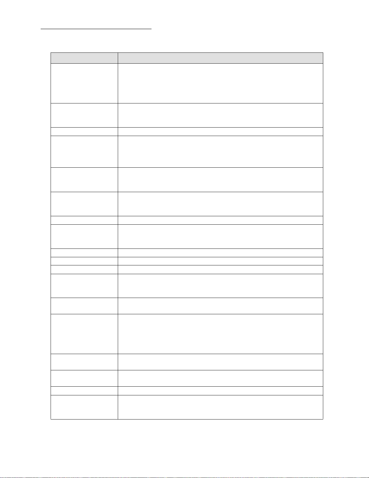
Micro-Ion Total Pressure Gauge
(Catalog #390802)
Interconnect Cable: Micro-Ion
Gauge to VQM Controller
(Catalog #802301-01 for 1
meter long, or 802301-03 for 3
meters long)
Demountable Envelope
Nipple (Catalog #801270)
for Nude MS Gauge
T-Flange (Catalog #
801272) and 3 Bolt Kits
(Catalog #801274-1)
Figure 2-2 Standard Components of the Vacuum Quality Monitor System
Figure 2-3 Optional Components of the Vacuum Quality Monitor System
18
Series 835 Vacuum Quality Monitor
Instruction Manual - 835000 - Rev. E

2 Introduction & Specifications
2.2 Receiving Inspection
Inspect all materials received for shipping damage. Confirm that your shipment includes all the
materials and options that were ordered. If materials are missing or damaged, the carrier that made
the delivery must be notified within 15 days of delivery in accordance with Interstate Commerce
regulations to file a valid claim with the carrier. Any damaged material, including all containers and
packaging, should be held for carrier inspection.
If your shipment is not correct for reasons other than shipping damage, contact Brooks Automation
Customer Service Department, 6450 Dry Creek Parkway, Longmont, Colorado 80503,
phone +1-303-652-4400, email csr-co@brooks.com.
2.3 Glossary of Terms
Table 2-1 Acronyms and Definitions
Ter m Definition
VQM Vacuum Quality Monitor
Series 835 VQM A combination of an ion trap mass spectrometer vacuum gauge and VQM Controller
integrated into an operational system that measures gases in a vacuum chamber.
Absolute partial pressure A partial-pressure display of gases in a chamber, showing the absolute pressure of
each gas.
ADC Analog-to-Digital Converter
AMU, amu Atomic Mass Units. The atomic mass unit is defined as 1/12th the weight of a single
carbon-isotope 12 atom.
Anharmonic An oscillating system that is not undergoing simple harmonic motion; not harmonic
Analog Input The Series 835 controller has one analog input port that can be used to digitize
analog voltage signals from external sources. A common use of the analog input port
is to collect total pressure readings from the analog output of an ionization gauge
controller. See Section 2.4.7.
Analog Output The Series 835 VQM Controller has one analog output. When Enabled, it is
electrically connected to the voltage output of the electrometer, and the signal is
available for each executed MS scan. See Section 2.4.7
API Application Programming Interface.
ART MS Autoresonant Ion Trap Mass Spectrometer. An ion trap mass spectrometer that stores
ions using purely electrostatic potentials and that relies on autoresonant excitation of
ion motions in an anharmonic trapping potential for mass selective ejection. See Ion
Trap.
Auto Tune A procedure that can be initiated in the Viewer Application software that optimizes
several voltages of the MS Gauge.
Connection An established USB communication link between a Host/PC and a specific VQM
Controller, or an RS-485 link between the VQM Controller and the Total Pressure
Module.
Controller (835) The Series 835 VQM Controller. The VQM Viewer software installation includes 3
APIs that the user can use to create custom applications. One in .NET, one in
LabVIEW, and one in C++.
Series 835 Vacuum Quality Monitor
Instruction Manual - 835000 - Rev. E
19
2 Introduction & Specifications
Table 2-1 Acronyms and Definitions
Ter m Definition
DAQ Data Acquisition - Data acquisition is the process of measuring an electrical or
physical phenomenon such as voltage, current, temperature, pressure, or sound. A
DAQ is used to acquire, analyze, and present information. DAQ systems typically use
fast ADCs to digitize the analog voltage readings related to the signal being
measured.
Data Output The Series 835 VQM Controller supports USB communication with a Host/PC via a
high level, text-based command-set. The data output means a digital message that
contains information that is associated with a measured value.
FWHM The width of a mass peak at the 50% amplitude points.
Gas Library The Viewer Application software has a library of 10 gases.
The 10 gases are: Hydrogen, Helium, Nitrogen, Oxygen, Water, Carbon Monoxide,
Argon, Carbon Dioxide, Krypton, and Neon. When the Viewer Application is in Gas
display mode, fitted gases from this list will be displayed along with residual AMUs.
Gas Measurement The relative partial pressure of one or more amu peaks. For example, Air could be
defined as a ratiometric relationship of 78% Nitrogen (amu peak 28), 21% Oxygen
(amu peak 32), and 0.9% Argon (amu peak 40).
Gauge (Sensor) The Mass Spec Gauge is a gas-sensor device (transducer) mounted to the vacuum
chamber that provides species mass spectral readings to the 835 VQM Controller.
"Gauge" also indicates the Total Pressure Measurement Gauge.
Host/PC Remote user interface (being executed on a PC) to the VQM Controller.
Ion Trap A physical device that captures and stores ions based on electrostatic, electrodynamic
or magnetic confinement fields. Most ion traps used for analytical purposes also offer
the capability to mass selectively eject the stored ions.
ITMS Ion Trap Mass Spectrometry
MDPP Minimum Detectable Partial Pressure
Mass range Smallest to largest mass that can be measured with the VQM system.
Mass Spectrometry An analytical technique that measures the mass-to-charge ratio of charged particles. It
is used to determine masses of particles or to determine the elemental composition of
a sample or molecule.
Maximum pressure The maximum total pressure where the device operates with a known and acceptable
accuracy.
Micro-Ion Gauge A Granville-Phillips Wide-Range Series 390802 Micro-Ion ATM Gauge with RS485
interface to provide vacuum chamber total pressure measurement. The option
includes a 1-meter or 3-meters long interconnect cable. The Micro-Ion Gauge
connects to the VQM Controller via a 15-pin "D" connector on the rear of the 835
VQM Controller.
MS or Mass Spec Mass Spectrometer. An instrument that can measure the masses and relative
concentrations of atoms and molecules.
MS Gauge Mass Spectrometer Gauge: The vacuum sensor used by the 835 VQM System to
determine and measure the gases in the vacuum chamber.
-3
msec or ms Millisecond -- 1000th (10
m/z or m/Q Mass-to-charge ratio - defined as the atomic weight of an ion divided by its charge.
A number defining how a particle will respond to an electric or magnetic field that
can be calculated by dividing the mass of a particle by its charge.
) of 1 second
20
Series 835 Vacuum Quality Monitor
Instruction Manual - 835000 - Rev. E
2 Introduction & Specifications
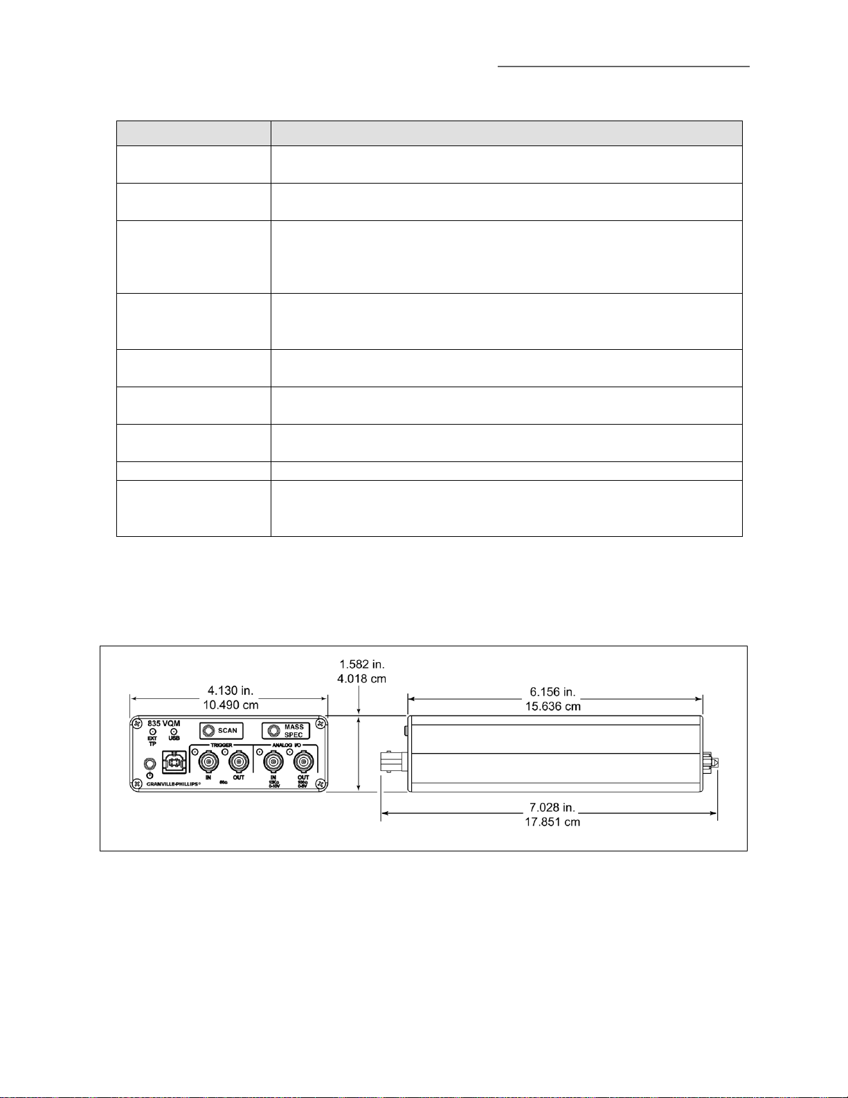
The VQM Controller is a
benchtop mount unit.
Table 2-1 Acronyms and Definitions
Ter m Definition
PP or partial pressure The partial pressure of a component in a gas mixture is the pressure that the gas
would exert on the vacuum system if all other gases were removed from the chamber.
Ratiometric partial
pressure
Resolution Resolution measures the ability to distinguish peaks of very similar mass-to-charge
Resolving power (m/Δm) Resolution is measured as resolving power, which is a given mass-to-charge (m/Q)
Session Interactive monitor/control transactions occurring between the Host and a specific
Total Pressure
Measurement Gauge
TP or Total Pressure Total pressure is equal to the sum of the partial pressures. Total pressure can be
Trend A plot of a single or multiple values against time.
TM
VQI
A partial-pressure display of gases in a chamber, showing the contribution of each gas
relative to the others. Units: %, parts-per-million, etc.
ratio. The resolution at a specific mass-to-charge m/Q is measured as the FWHM
(50% peak height) for its mass peak in the spectrum. Higher resolution values are
desirable.
ratio and the FWHM, ΔM 50%, R=M/ΔM. Large resolution power is desirable to fully
differentiate the mass peaks.
VQM Controller.
See Micro-Ion Gauge.
provided to the box via the Micro-Ion Gauge or Analog Input (configurable).
Vacuum Quality IndexTM: allows the creation of Boolean expressions to trigger audio
alerts and drive the trigger out on the Controller in response to real-time data from the
Controller.
2.4 Specifications
2.4.1 Dimensional Illustrations
Figure 2-4 VQM Controller Dimensions
Series 835 Vacuum Quality Monitor
Instruction Manual - 835000 - Rev. E
21
2 Introduction & Specifications
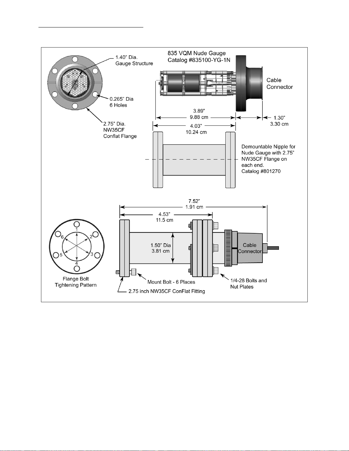
For the Nude Gauge
configuration, the inside
diameter of the vacuum port to
which the Gauge is mounted
MUST be 1.430 inches (3.632
mm) or larger. Damage to the
gauge will result if the inside
diameter is less than specified.
Figure 2-5 VQM Mass Spectrometer Gauge Dimensions
22
Series 835 Vacuum Quality Monitor
Instruction Manual - 835000 - Rev. E
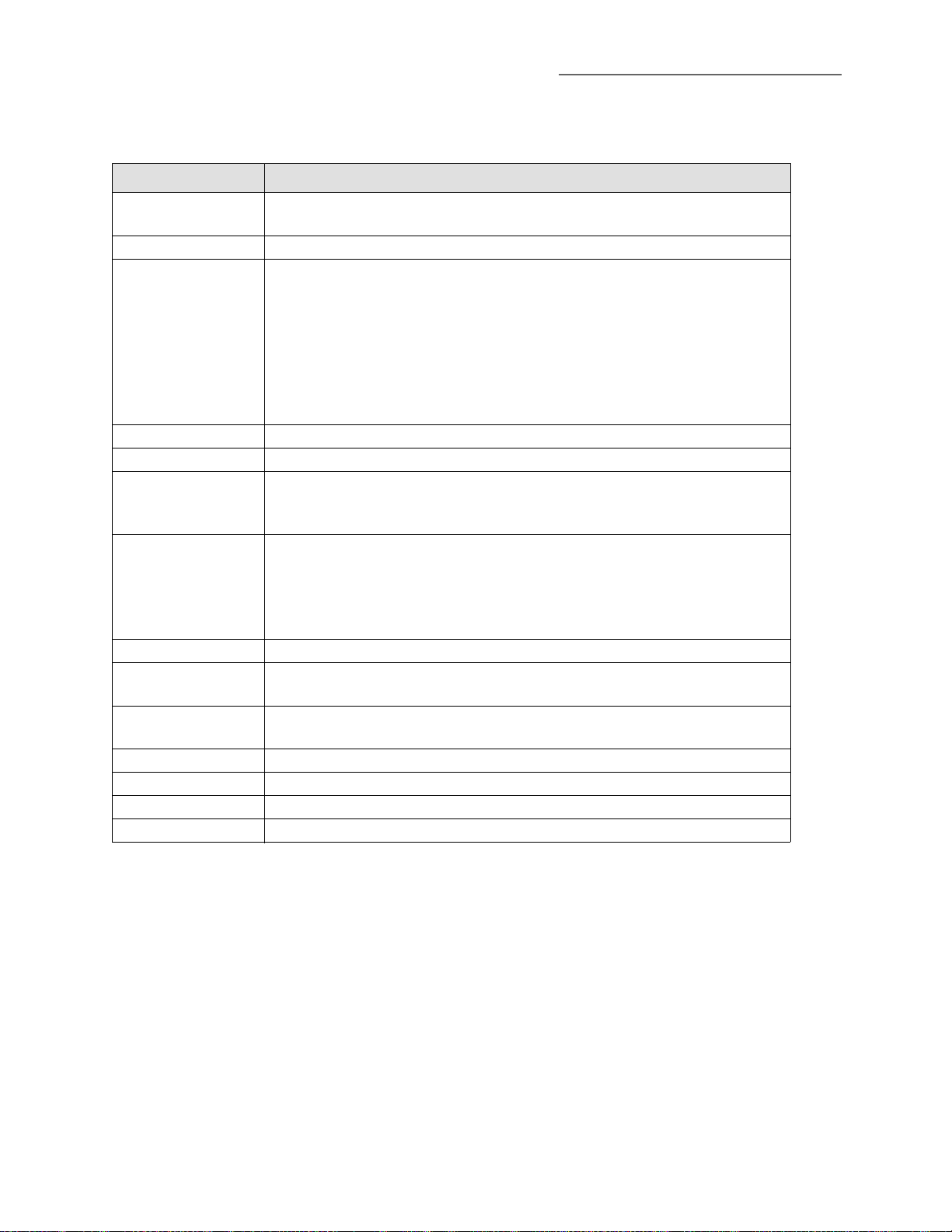
2.4.2 VQM Controller Specifications
Table 2-2 VQM Controller Specifications
Parameter Specification
Mass Range/Scan
Time
Scan RF Frequency 2.65 MHz to ~147 kHz
Inputs and Outputs
1. Trigger In (BNC)
2. Trigger Out (BNC)
3. Analog In (BNC)
4. Analog Out (BNC)
5. USB (Type B)
6. MS Gauge
7. Ext TP Gauge
LEDs on front panel EXT TP, USB, Trigger IN, Trigger OUT, Analog IN, Analog OUT
Buttons on front panel Power, Scan, Mass Spec
Input Power -
Controller and MS
Gauge Only
Input power when
using the optional
Series 390802
Micro-Ion ATM
Gauge
Input Power Plug DC power jack, 5.5 mm OD x 2.5 mm ID x 11 mm long
Operating
Temperature
Non-operating
Temperature
Relative Humidity < 90%, non-condensing
Physical Dimensions See Figure 2-5
Weight 720 grams (25 ounces)
IP Rating IP20
1 - 145 amu in 85 ms, or 1 - 300 amu in 125 msec
Analog I/O, Trigger I/O, USB, Mass Spec Gauge, External Total Pressure Gauge
Ω, positive TTL, 1 msec, minimum pulse width
1. 50
Ω, Active High, TTL frame scan, or VQI output
2. 50
3. 10K Ω, 0-10 V, 12 bit resolution
4. 0 V to +5 V with 30 KHz 3 db bandwidth
5. 2.0, full speed, 12 Mb/sec **
6. 14-Pin connector for the Mass Spectrometer Gauge
7. 15-Pin "D" connector for the optional Total Pressure Measurement Kit
24 Vdc, 15 Watts required, 8 Watts typical
NOTE: The System MUST be properly grounded. See Section 3.8 and Figure 3-15 on
page 43.
24 Vdc, 75 Watts maximum
NOTE: The System MUST be properly grounded. See Section 3.8 and Figure 3-15 on
page 43.
o
C to 40 oC (32 oF to 104 oF)
0
o
0
C to 80 oC (32 oF to 176 oF)
2 Introduction & Specifications
Specifications and dimensions are subject to change without notice.
** USB cable must meet the specifications for USB 2.0, USB-IF.
Series 835 Vacuum Quality Monitor
Instruction Manual - 835000 - Rev. E
23

2 Introduction & Specifications
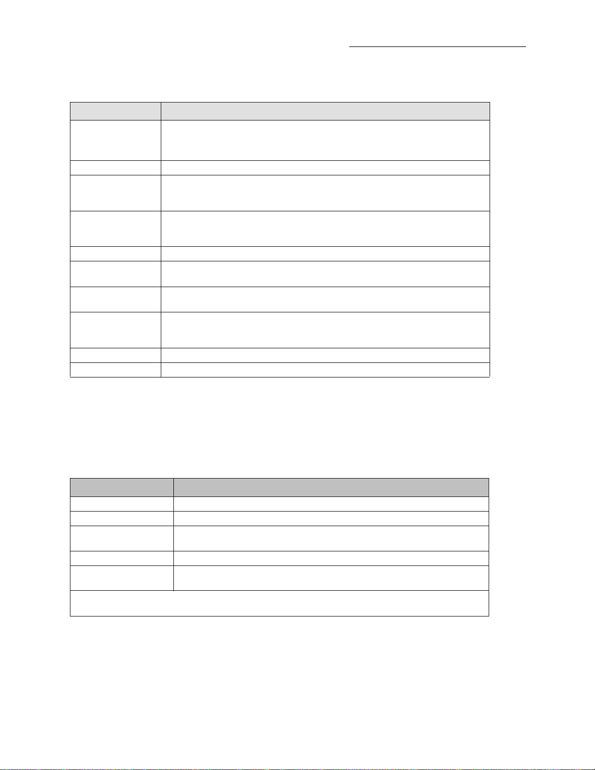
2.4.3 Mass Spectrometer Gauge Specifications
Table 2-3 VQM MS Gauge Specifications
Parameter Specification
Measurement Range
Partial Pressure: 1 x 10
Total Pressure with the optional Micro-Ion Total Pressure Measurement Gauge: ATM to
-9
1 x 10
Torr. For total pressure measurement below 1 x 10⁻⁹ Torr, use a
Granville-Phillips Series 370 Vacuum Gauge Controller.
Mass Range 1 to 145 amu, or 1 to 300 amu (Relative Partial Pressure or Partial Pressure)
Mass Separator Type Autoresonant Ion Trap
Resolution (m/
Δm )
150 typical, 100 minimum *
Dynamic Range 2 decades for single scan, >3 decades with averaging
Response Time ~125 msec for 1-300 amu at default VQM Controller settings
Filament Single Yttria coated Iridium, field replaceable
Operating
o
C to 50 oC (32 oF to 122 oF), non-condensing
0
Temperature
Detector Type Continuous Dynode Electron Multiplier, field replaceable
Bakeout Temperature
o
C maximum, non-operating, with the cable disconnected, degas not required
200
Mounting Flange NW35CF 2.75 inch ConFlat type
Interconnect cable 1, 3, or 20 meters long
Physical Dimensions See Figure 2-5
Weight 420 grams (14.8 ounces)
Materials exposed to
process environment
304L Stainless Steel, 316L Stainless Steel, Alumina Ceramic, Al2O3 98% Min., Nickel,
Molybdenum, Ag/Cu eutectic braze, Gold, Iridium, Yttria, Y2O3 99.95%, Lead Glass
(multiplier body), Chromium
Heater Jacket for the
120 VAC, 34 W or 240 VAC, 34 W
MS Gauge
-5
Torr to UHV
* Measured at 28 amu, N
24
Specifications and dimensions are subject to change without notice.
at 2 x10⁻⁷ Torr at default VQM Controller settings. Δm measured at FWHM.
2
Series 835 Vacuum Quality Monitor
Instruction Manual - 835000 - Rev. E
2.4.4 Viewer Software Specifications
Table 2-4 VQM Viewer Software Specifications
Parameter Specification
Top Ten Gase s
Display Table
Gas Recipe Fit Correlation fit against expected gas spectrum
Total Pressure Trend
Graph
Pressure Trend of
User Selected Gases
or Masses
Sensor Spectrum Displayed, 1-145 or 1- 300 amu
Capture, Display
Information
Logging, VQM Data Comma separated variable (csv) (MS Excel Compatible)
VQM Controller
Configuration
Leak Detection User assigned limit and leak gas detection, audible tone
Software interface API, LabVIEW VIs
Automatic listing by species or amu. The Viewer Application software has a library of
10 gases; Hydrogen, Helium, Nitrogen, Oxygen, Water, Carbon Monoxide, Argon,
Carbon Dioxide, Krypton, and Neon.
-9
Range: ATM to 10
analog input from another pressure source, such as a Granville-Phillips Series 370
Stabil-Ion Gauge Controller.)
User selection in display table. Maximum of 10 displayed.
1-300 amu scan, total pressure, timestamp
1-300 amu scan, total pressure, timestamp, status per scan
Mass Spec Mode: ON / OFF
Acquisition: via application control or external trigger control
Mass Spectrometer Calibration: single gas/mass, manual
Torr (Requires Micro-Ion ATM Gauge Total Pressure Gauge or
2 Introduction & Specifications
Specifications and dimensions are subject to change without notice.
2.4.5 Host/PC Requirements
The VQM System can be used without a Host/PC. A Host/PC is required (1) to use the VQM Viewer
Application Software, (2) control the VQM Controller from a remote location, or (3) program
additional control functions that provide process automation or input/output data.
Table 2-5 Host/PC Requirements
Parameter Requirements
Processor/Memory Intel Core 2 Duo T7250@2Ghz with 2.56G of Ram or equivalent
Display Resolution Minimum: 1024 x 768 pixels, larger to take advantage of resizing
Operating System Windows 7 (32 or 64 bit)/ Windows XP (32 bit) SP2, .NET 3.5 Framework SP1
(provided)
Disk Space Minimum: 1.6 GB. (More will be needed for large log files.)
Optional Development
Environment
Minimum requirements are for one PC connected to one VQM Controller. Four or Eight core systems are
recommended when driving multiple Controllers.
LabVIEW 2011 required to use LabVIEW VIs.
.NET development platform required to use API. (tested with Visual Studio 2010.)
Series 835 Vacuum Quality Monitor
Instruction Manual - 835000 - Rev. E
25
2 Introduction & Specifications
2.4.6 Trigger Input/Output Specifications
Table 2-6 Trigger Input and Output Connections
Port Specification
Trigger IN port (BNC) • Input Impedance: 50
• Trigger Logic: Edge Trigger, Low to High, TTL Levels
• Minimum Pulse Width: 1 msec
Trigger OUT port (BNC) • Output Impedance: 50
• Trigger Logic: Low to High, TTL Levels
Trigger IN
Use the Trigger IN port to deliver valid external trigger pulses to the VQM Controller to execute
single mass spectrometry scans synchronous with external events. See Section 5.5.1 for more
information.
Trigger OUT
Use the Trigger OUT port to access the output trigger pulses available to time frame the MS analog
out signal available from the VQM Controller or driven by VQI. See Section 5.5.2 and Section
8.4.11 for more information.
Ω
Ω
Logic Level Outputs
Trigger Logic: TTL Active HIGH. The output level becomes High as the MS scan is initiated. The
output becomes Low again at the end of the scan. Use the rising edge to trigger external DAQ
systems. Use the length of the pulse to frame the scan. The output trigger pulse remains low
between completion of the previous scan and the start of a new scan (in continuous scan mode).
2.4.7 Analog Input/Output Specifications
Table 2-7 Analog Input/Output Connections
Port Specification
Analog IN port (BNC) • Input Impedance: 10K
• Voltage Range: 0-10 V
• ADC Specs: 12 bit resolution
Analog OUT port (BNC) • Output Impedance:100
• Voltage Range: 0-5 V
• Trans-impedance Gain: 2X electrometer voltage
output with 30kHz low pass filter
Analog IN
Use the Analog IN port to connect sensors with analog voltage signal outputs to the VQM
Controller. This functionality allows sensor integration and signal synchronization. The Analog IN
port is electrically connected to a 12-bit ADC converter and can be treated as a total pressure input
by the VQM Viewer Software. See Section 5.5.3.
Ω
Ω
Analog OUT
Use the Analog OUT port to monitor the voltage output of the electrometer during MS Scans. The
Analog OUT port is electrically connected to the voltage output of the electrometer via a gain=2X
voltage amplifier which also has a 30 kHz low pass filter attached to its output. The MS analog out
signal is available for each executed MS scan. See Section 5.5.4.
26
Series 835 Vacuum Quality Monitor
Instruction Manual - 835000 - Rev. E

2 Introduction & Specifications
2.5 Compliance
All components of the Vacuum Quality Measurement System are compliant with the following:
EMC......................... EN61326-1
Safety....................... EN61010-1
Environmental.......... RoHS Compliant
IP Rating .................. IP20
* Brooks Automation/Granville-Phillips recommends the use of interconnect cables of 3 meters or
less in length for connection to the VQM Controller. The attachment of any cable greater than 3
meters in length will result in failure of the system to meet CE Compliance specifications; more
specifically, the ability to meet the Conducted RF Immunity standard IEC 61000-4-6. The test for
this standard couples RF into I/O cables over the same RF frequency range that is injected into the
Ion Trap, directly affecting the signal. This includes all generic cables such as USB and BNC cables
that are connected to the VQM Controller. Use of cables longer than 3 meters should not affect the
performance of the system, but the system will not be CE Compliant.
2.6 Warranty Information
Brooks Automation, Inc. warrants that new 835 Series VQM Products shall be free of defects in
material and workmanship for a period of 18 months (excluding consumables) from the date of
shipment from the manufacturer or from a Brooks Automation, Inc. regional office or supply center.
The gauge filament and electron multiplier are consumables and are not warranted against wear
due to use, accelerated failures in harsh environments, or misuse through improper handling or
configuration.
Series 835 Vacuum Quality Monitor
Instruction Manual - 835000 - Rev. E
27

2 Introduction & Specifications
Notes:
28
Series 835 Vacuum Quality Monitor
Instruction Manual - 835000 - Rev. E

Chapter 3
3 Hardware Installation
3.1 Introduction
Initial installation and setup requires mounting the VQM® Mass Spectrometer Gauge (MS Gauge) to
your vacuum chamber and making the necessary interconnections to the bench-top mounted VQM
Controller. This chapter describes the process of unpacking, checking and installing the VQM
System on a vacuum chamber. Initial installation and setup requires mounting the MS Gauge and
the optional Micro-Ion Total Pressure Measurement Gauge on a vacuum chamber and making the
necessary interconnections to the bench-top mounted VQM Controller. Read and follow all
installation instructions and safety procedures listed in this chapter to assure operator safety and
optimum performance for the instrument.
NOTE: Do not apply power to the instrument (Controller) until specifically directed in
NOTE: Do not operate the VQM System if the pressure in the vacuum system exceeds
3.2 Terms used in this chapter
Table 3-1 Term and Definitions
the Initial Operation Procedure in Chapter 8.
−5
Torr. Use a Pressure Reduction System if higher pressures are present.
1x10
Ter m Definition
Controller The VQM Mass Spectrometer Gauge Controller. See Figure 3-1.
Micro-Ion Gauge The Series 390802 Micro-Ion ATM Total Pressure Measurement Gauge. See Figure 2-3,
Figure 3-2, and Figure 3-6. Separate instruction manuals (p/n 390001 & p/n 390015)
are provided with the Micro-Ion Gauge.
MS Gauge The Mass Spectrometer Gauge that is connected to the vacuum chamber. The MS
Gauge can be configured as a nude gauge (see below) or mounted inside a
demountable envelope (full-nipple). See Figure 2-5, Figure 3-3 and Figure 3-4.
Nude Gauge The Mass Spectrometer Gauge that is connected to the vacuum chamber, but the
sensors of the gauge are inside the chamber rather inside a nipple that is mounted to the
chamber. See Figure 2-5, Figure 3-3, and Figure 6-2.
T-Flange An optional mounting flange for the purpose of mounting the MS Gauge and the
Micro-Ion Gauge at the same port on the vacuum chamber. See Figure 2-3 and Figure
3-2.
UHV
VQM Vacuum Quality Monitor - refers to the VQM System, which consists of the VQM
Ultra High Vacuum - usually referring to pressures below 10
Controller and the VQM Mass Spectrometer Gauge.
-9
Torr.
Series 835 Vacuum Quality Monitor
Instruction Manual - 835000 - Rev. E
29

3 Hardware Installation
3.3 Unpacking the Components
3.3.1 Before You Open the Boxes
• Adhere to good high vacuum practices throughout the Mass Spectrometer Gauge installation
procedure.
• Select a clean and dust free area next to the vacuum port before the Mass Spectrometer
Gauge installation process begins.
• To reduce the chances of contamination and to maximize the lifetime of the electron
®
multiplier detector, do not break the seal of the metalized Mylar
mass spectrometer gauge until you are ready to install it on the vacuum chamber.
• Take a moment at this time to review the Electron Multiplier Detector in Section 7.6
• Inspect all components of the VQM System upon unpacking. Report any damage or missing
components to Brooks Automation, Inc.
3.3.2 Checklist of Components
3.3.2.1 Standard Equipment - See Figure 3-1
• VQM Mass Spectrometer Gauge (in a vacuum-sealed metalized Mylar® bag)
• VQM Controller Unit, bench-top mount
• Cable, interconnect, VQM Controller-to-Mass Spectrometer Gauge
• Cable, interconnect, USB, VQM Controller-to-Computer
• Universal Power Supply for VQM System (AC to 24 Vdc)
• CD, VQM Viewer Application Software
bag used to package the
3.3.2.2 Optional Equipment
• Micro-Ion ATM Total Pressure Measurement Gauge
• Cable, interconnect, VQM Controller-to-Micro-Ion ATM Module
• Cable for Log/Linear analog pressure output from a Granville-Phillips Series 370 Ion Gauge
Controller
• Heater Jacket for the Mass Spectrometer Gauge
• Field replacement Filament Assembly Kit
• Field replacement Electron Multiplier
• Demountable envelope (Full-Nipple) for the Nude Mass Spectrometer Gauge
• T-Flange adapter
• Hardware bolt kit
30
Series 835 Vacuum Quality Monitor
Instruction Manual - 835000 - Rev. E
 Loading...