

Granville-Phillips 500 CCG Series Instruction Manual

Series 500
Granville-Phillips® Series 500 Cold Cathode
Gauge with Analog Output, 2 Setpoint Relays,
and optional RS-485 Digital Interface
Instruction Manual
Instruction manual part number 500001
Revision F - November 2016

Granville-Phillips Series 500 CCG Module

Series 500
Granville-Phillips® Series 500 Cold Cathode
Gauge with Analog Output, 2 Setpoint Relays,
and optional RS-485 Digital Interface
This instruction manual is for use with Granville-Phillips
Series 500 Cold Cathode Gauge with RS-485 Digital
Interface. A list of applicable catalog numbers is provided
on the following page.
Customer Service / Technical Support:
MKS Pressure and Vacuum Measurement Solutions
MKS Instruments, Inc., Granville-Phillips® Division
6450 Dry Creek Parkway
Longmont, Colorado 80503 USA
Tel: 303-652-4400
Fax: 303-652-2844
Email: mks@mksinst.com
MKS Corporate Headquarters
MKS Instruments, Inc.
2 Tech Drive, Suite 201
Andover, MA 01810 USA
Tel: 978-645-5500
Fax: 978-557-5100
Email: mks@mksinst.com
Instruction Manual
© 2016 MKS Instruments, Inc. All rights reserved.
Granville-Phillips
MKS Instruments, Inc. All other trademarks and registered trademarks are the
properties of their respective owners.
®
is a registered trademark, and mksinstTM is a trademark of

Granville-Phillips® Series 500 Cold Cathode Gauge
with optional RS-485 Digital Interface
Catalog numbers for Series 500 Cold Cathode Gauges
Gauge Assembly
Gauge with analog output, 2 setpoints, no display 500100 - ## - ### - #
Gauge with analog output, 2 setpoints, digital display 500101 - ## - ### - #
UHV Gauge with analog output, 2 setpoints, digital display 500501 - ## - ### - #
Setpoint Relays
2 relays 2
Calibration
Calibrated (Higher Accuracy) C
Standard S
Interface
RS-485 R4
Vacuum Connection
NW25KF E
NW40KF K
NW35CF (2.75 inch Conflat-type) G
Measurement Units
Tor r T
mBar M
Pascal P
Replacement Gauge (Sensor) 500200- # #
Calibration
Calibrated (Higher Accuracy) C
Standard S
Vacuum Connection
NW25KF E
NW40KF K
NW35CF (2.75 inch Conflat-type) G
Gauge Repair Kit (Field replaceable maintenance kit) 500600- K

Table of Contents
Chapter 1 General Information . . . . . . . . . . . . . . . . . . . . . . . . . . . . . . . . . . . . . . . . . . . . . . . . . . . . . . . . . . . . . . . 9
1.1 Receiving Inspection . . . . . . . . . . . . . . . . . . . . . . . . . . . . . . . . . . . . . . . . . . . . . . . . . . . . . . . . . . . . . . . . . 9
1.2 International Shipment . . . . . . . . . . . . . . . . . . . . . . . . . . . . . . . . . . . . . . . . . . . . . . . . . . . . . . . . . . . . . . . 9
1.3 Warranty . . . . . . . . . . . . . . . . . . . . . . . . . . . . . . . . . . . . . . . . . . . . . . . . . . . . . . . . . . . . . . . . . . . . . . . . . 9
1.4 Certification . . . . . . . . . . . . . . . . . . . . . . . . . . . . . . . . . . . . . . . . . . . . . . . . . . . . . . . . . . . . . . . . . . . . . . . 9
1.5 Service Guidelines . . . . . . . . . . . . . . . . . . . . . . . . . . . . . . . . . . . . . . . . . . . . . . . . . . . . . . . . . . . . . . . . . . 10
Chapter 2 Safety . . . . . . . . . . . . . . . . . . . . . . . . . . . . . . . . . . . . . . . . . . . . . . . . . . . . . . . . . . . . . . . . . . . . . . . . . . 11
2.1 Safety Introduction . . . . . . . . . . . . . . . . . . . . . . . . . . . . . . . . . . . . . . . . . . . . . . . . . . . . . . . . . . . . . . . . . 11
2.2 Magnets . . . . . . . . . . . . . . . . . . . . . . . . . . . . . . . . . . . . . . . . . . . . . . . . . . . . . . . . . . . . . . . . . . . . . . . . . 12
2.3 Grounding Requirements . . . . . . . . . . . . . . . . . . . . . . . . . . . . . . . . . . . . . . . . . . . . . . . . . . . . . . . . . . . . 13
2.4 High Voltage . . . . . . . . . . . . . . . . . . . . . . . . . . . . . . . . . . . . . . . . . . . . . . . . . . . . . . . . . . . . . . . . . . . . . 14
2.5 Over Pressure Conditions . . . . . . . . . . . . . . . . . . . . . . . . . . . . . . . . . . . . . . . . . . . . . . . . . . . . . . . . . . . . 14
2.6 System and Environment . . . . . . . . . . . . . . . . . . . . . . . . . . . . . . . . . . . . . . . . . . . . . . . . . . . . . . . . . . . . 15
2.7 Safety Interlocks . . . . . . . . . . . . . . . . . . . . . . . . . . . . . . . . . . . . . . . . . . . . . . . . . . . . . . . . . . . . . . . . . . . 16
2.8 Responsibility . . . . . . . . . . . . . . . . . . . . . . . . . . . . . . . . . . . . . . . . . . . . . . . . . . . . . . . . . . . . . . . . . . . . . 16
2.9 Damage Requiring Service . . . . . . . . . . . . . . . . . . . . . . . . . . . . . . . . . . . . . . . . . . . . . . . . . . . . . . . . . . . 16
Chapter 3 Introduction . . . . . . . . . . . . . . . . . . . . . . . . . . . . . . . . . . . . . . . . . . . . . . . . . . . . . . . . . . . . . . . . . . . . 19
3.1 General Description . . . . . . . . . . . . . . . . . . . . . . . . . . . . . . . . . . . . . . . . . . . . . . . . . . . . . . . . . . . . . . . . 19
3.2 Intended Use . . . . . . . . . . . . . . . . . . . . . . . . . . . . . . . . . . . . . . . . . . . . . . . . . . . . . . . . . . . . . . . . . . . . . 19
3.2.1 Improper Use . . . . . . . . . . . . . . . . . . . . . . . . . . . . . . . . . . . . . . . . . . . . . . . . . . . . . . . . . . . . . . . 19
3.3 Transportation . . . . . . . . . . . . . . . . . . . . . . . . . . . . . . . . . . . . . . . . . . . . . . . . . . . . . . . . . . . . . . . . . . . . 20
3.4 Storage . . . . . . . . . . . . . . . . . . . . . . . . . . . . . . . . . . . . . . . . . . . . . . . . . . . . . . . . . . . . . . . . . . . . . . . . . . 20
3.5 Specifications . . . . . . . . . . . . . . . . . . . . . . . . . . . . . . . . . . . . . . . . . . . . . . . . . . . . . . . . . . . . . . . . . . . . . 20
3.5.1 Dimensions . . . . . . . . . . . . . . . . . . . . . . . . . . . . . . . . . . . . . . . . . . . . . . . . . . . . . . . . . . . . . . . . 21
3.6 Electronics Enclosure . . . . . . . . . . . . . . . . . . . . . . . . . . . . . . . . . . . . . . . . . . . . . . . . . . . . . . . . . . . . . . . 22
3.6.1 Control Panel LEDs . . . . . . . . . . . . . . . . . . . . . . . . . . . . . . . . . . . . . . . . . . . . . . . . . . . . . . . . . . 22
3.6.2 Input/Output Connectors . . . . . . . . . . . . . . . . . . . . . . . . . . . . . . . . . . . . . . . . . . . . . . . . . . . . . 23
3.6.3 USB Service Port . . . . . . . . . . . . . . . . . . . . . . . . . . . . . . . . . . . . . . . . . . . . . . . . . . . . . . . . . . . . 23
Chapter 4 Installation . . . . . . . . . . . . . . . . . . . . . . . . . . . . . . . . . . . . . . . . . . . . . . . . . . . . . . . . . . . . . . . . . . . . . 25
4.1 Introduction . . . . . . . . . . . . . . . . . . . . . . . . . . . . . . . . . . . . . . . . . . . . . . . . . . . . . . . . . . . . . . . . . . . . . . 25
4.2 Vacuum Gauge Connection (mechanical) . . . . . . . . . . . . . . . . . . . . . . . . . . . . . . . . . . . . . . . . . . . . . . . . 25
4.2.1 Mounting Location and Orientation . . . . . . . . . . . . . . . . . . . . . . . . . . . . . . . . . . . . . . . . . . . . . 26
4.2.2 Dimensions . . . . . . . . . . . . . . . . . . . . . . . . . . . . . . . . . . . . . . . . . . . . . . . . . . . . . . . . . . . . . . . . 27
4.2.3 Attach the Gauge to the Vacuum Chamber . . . . . . . . . . . . . . . . . . . . . . . . . . . . . . . . . . . . . . . . 27
4.3 Power and Input/Output Cable Connections . . . . . . . . . . . . . . . . . . . . . . . . . . . . . . . . . . . . . . . . . . . . . 31
4.3.1 Power & Communications Connector . . . . . . . . . . . . . . . . . . . . . . . . . . . . . . . . . . . . . . . . . . . . 32
4.3.2 Process Control & Diagnostics Connector . . . . . . . . . . . . . . . . . . . . . . . . . . . . . . . . . . . . . . . . . 33
4.4 Grounding the Gauge to the Vacuum Chamber . . . . . . . . . . . . . . . . . . . . . . . . . . . . . . . . . . . . . . . . . . . 34
Chapter 5 Initial Activation of the Module . . . . . . . . . . . . . . . . . . . . . . . . . . . . . . . . . . . . . . . . . . . . . . . . . . . . . 35
5.1 Activating the Cold Cathode Gauge/Electronics . . . . . . . . . . . . . . . . . . . . . . . . . . . . . . . . . . . . . . . . . . . 35
5.2 On-Board Diagnostics . . . . . . . . . . . . . . . . . . . . . . . . . . . . . . . . . . . . . . . . . . . . . . . . . . . . . . . . . . . . . . 37
5.2.1 Diagnostic Test Details . . . . . . . . . . . . . . . . . . . . . . . . . . . . . . . . . . . . . . . . . . . . . . . . . . . . . . . . 37
5.2.2 Power-On Self-Test (POST) . . . . . . . . . . . . . . . . . . . . . . . . . . . . . . . . . . . . . . . . . . . . . . . . . . . . 38
5.2.3 High-Voltage Timeout . . . . . . . . . . . . . . . . . . . . . . . . . . . . . . . . . . . . . . . . . . . . . . . . . . . . . . . . 38
5.2.4 Diagnostic Digital Input . . . . . . . . . . . . . . . . . . . . . . . . . . . . . . . . . . . . . . . . . . . . . . . . . . . . . . . 39
Chapter 6 Theory of Operation . . . . . . . . . . . . . . . . . . . . . . . . . . . . . . . . . . . . . . . . . . . . . . . . . . . . . . . . . . . . . . 41
6.1 Basic Theory of Operation . . . . . . . . . . . . . . . . . . . . . . . . . . . . . . . . . . . . . . . . . . . . . . . . . . . . . . . . . . . 41
6.2 Starting the Plasma . . . . . . . . . . . . . . . . . . . . . . . . . . . . . . . . . . . . . . . . . . . . . . . . . . . . . . . . . . . . . . . . . 41
6.3 Starting at Low Pressure . . . . . . . . . . . . . . . . . . . . . . . . . . . . . . . . . . . . . . . . . . . . . . . . . . . . . . . . . . . . . 41
6.4 Contamination . . . . . . . . . . . . . . . . . . . . . . . . . . . . . . . . . . . . . . . . . . . . . . . . . . . . . . . .
6.4.1 Process Gas Contamination . . . . . . . . . . . . . . . . . . . . . . . . . . . . . . . . . . . . . . . . . . . . . . . . . . . . 42
6.4.2 Line of Site By-Products . . . . . . . . . . . . . . . . . . . . . . . . . . . . . . . . . . . . . . . . . . . . . . . . . . . . . . . 42
6.4.3 Pressure Dose and Gauge Lifetime . . . . . . . . . . . . . . . . . . . . . . . . . . . . . . . . . . . . . . . . . . . . . . . 42
6.5 Electronics Description . . . . . . . . . . . . . . . . . . . . . . . . . . . . . . . . . . . . . . . . . . . . . . . . . . . . . . . . . . . . . . 42
Series 500 Cold Cathode Vacuum Gauge
Instruction Manual - 500001
. . . . . . . . . . . . 41
5

6.5.1 High Voltage Power Supply . . . . . . . . . . . . . . . . . . . . . . . . . . . . . . . . . . . . . . . . . . . . . . . . . . . . 42
6.5.2 Electrometer . . . . . . . . . . . . . . . . . . . . . . . . . . . . . . . . . . . . . . . . . . . . . . . . . . . . . . . . . . . . . . . . 43
6.5.3 Calculating Pressure . . . . . . . . . . . . . . . . . . . . . . . . . . . . . . . . . . . . . . . . . . . . . . . . . . . . . . . . . . 43
6.5.4 Analog I/O . . . . . . . . . . . . . . . . . . . . . . . . . . . . . . . . . . . . . . . . . . . . . . . . . . . . . . . . . . . . . . . . . 43
6.5.4.1 Analog Output . . . . . . . . . . . . . . . . . . . . . . . . . . . . . . . . . . . . . . . . . . . . . . . . . . . . . . . 43
6.5.5 Digital I/O . . . . . . . . . . . . . . . . . . . . . . . . . . . . . . . . . . . . . . . . . . . . . . . . . . . . . . . . . . . . . . . . . 44
6.5.6 Setpoint Relays . . . . . . . . . . . . . . . . . . . . . . . . . . . . . . . . . . . . . . . . . . . . . . . . . . . . . . . . . . . . . . 44
6.5.7 Microprocessor . . . . . . . . . . . . . . . . . . . . . . . . . . . . . . . . . . . . . . . . . . . . . . . . . . . . . . . . . . . . . . 44
6.6 Pressure Correction Factors . . . . . . . . . . . . . . . . . . . . . . . . . . . . . . . . . . . . . . . . . . . . . . . . . . . . . . . . . . 45
6.6.1 Gas Species Correction . . . . . . . . . . . . . . . . . . . . . . . . . . . . . . . . . . . . . . . . . . . . . . . . . . . . . . . . 45
6.6.2 Pressure Correction Factor Multiplier . . . . . . . . . . . . . . . . . . . . . . . . . . . . . . . . . . . . . . . . . . . . . 45
6.6.3 Sensitivity Factor . . . . . . . . . . . . . . . . . . . . . . . . . . . . . . . . . . . . . . . . . . . . . . . . . . . . . . . . . . . . 45
Chapter 7 G-P Connect Software . . . . . . . . . . . . . . . . . . . . . . . . . . . . . . . . . . . . . . . . . . . . . . . . . . . . . . . . . . . . . 47
7.1 GP Connect Application . . . . . . . . . . . . . . . . . . . . . . . . . . . . . . . . . . . . . . . . . . . . . . . . . . . . . . . . . . . . 47
7.2 GP Connect Software Installation . . . . . . . . . . . . . . . . . . . . . . . . . . . . . . . . . . . . . . . . . . . . . . . . . . . . . . 47
7.3 Starting the GP Connect Software . . . . . . . . . . . . . . . . . . . . . . . . . . . . . . . . . . . . . . . . . . . . . . . . . . . . . 51
7.4 Connecting to the CCG Electronics . . . . . . . . . . . . . . . . . . . . . . . . . . . . . . . . . . . . . . . . . . . . . . . . . . . . 52
7.5 Getting CCG Electronics Status Information . . . . . . . . . . . . . . . . . . . . . . . . . . . . . . . . . . . . . . . . . . . . . 53
7.6 Configuring the CCG Electronics . . . . . . . . . . . . . . . . . . . . . . . . . . . . . . . . . . . . . . . . . . . . . . . . . . . . . 54
7.6.1 Changing the Communication Settings . . . . . . . . . . . . . . . . . . . . . . . . . . . . . . . . . . . . . . . . . . . 55
7.6.2 Setting Pressure Units and Factors: . . . . . . . . . . . . . . . . . . . . . . . . . . . . . . . . . . . . . . . . . . . . . . . 55
7.6.3 Naming the Sensor . . . . . . . . . . . . . . . . . . . . . . . . . . . . . . . . . . . . . . . . . . . . . . . . . . . . . . . . . . . 57
7.6.4 Setting the Gauge Auto ON Behavior . . . . . . . . . . . . . . . . . . . . . . . . . . . . . . . . . . . . . . . . . . . . 57
7.6.5 Setting the Gauge Auto Off Behavior . . . . . . . . . . . . . . . . . . . . . . . . . . . . . . . . . . . . . . . . . . . . . 59
7.6.6 Setting the Date and Time on the Electronics . . . . . . . . . . . . . . . . . . . . . . . . . . . . . . . . . . . . . . . 59
7.6.7 Disabling Further Commands or Disabling HV button presses . . . . . . . . . . . . . . . . . . . . . . . . . 60
7.6.8 Configuring the Analog Output Settings . . . . . . . . . . . . . . . . . . . . . . . . . . . . . . . . . . . . . . . . . . 60
7.6.9 Configuring the Relays . . . . . . . . . . . . . . . . . . . . . . . . . . . . . . . . . . . . . . . . . . . . . . . . . . . . . . . . 61
7.6.9.1 Manual Control of Relays . . . . . . . . . . . . . . . . . . . . . . . . . . . . . . . . . . . . . . . . . . . . . . . 61
7.6.9.2 Automatic Relay Based on Internal Pressure . . . . . . . . . . . . . . . . . . . . . . . . . . . . . . . . . 61
7.6.9.3 Automatic Relay Based on External Voltage . . . . . . . . . . . . . . . . . . . . . . . . . . . . . . . . . 62
7.6.9.4 Automatic Relay Based on Service Error . . . . . . . . . . . . . . . . . . . . . . . . . . . . . . . . . . . . 63
7.6.9.5 Digital IN Disable of Automatic Relay Set Points . . . . . . . . . . . . . . . . . . . . . . . . . . . . . 64
7.6.9.6 Restoring Factory Defaults . . . . . . . . . . . . . . . . . . . . . . . . . . . . . . . . . . . . . . . . . . . . . . 65
7.7 Turning the Cold Cathode Gauge ON or OFF . . . . . . . . . . . . . . . . . . . . . . . . . . . . . . . . . . . . . . . . . . . 65
7.8 Resetting the Gauge . . . . . . . . . . . . . . . . . . . . . . . . . . . . . . . . . . . . . . . . . . . . . . . . . . . . . . . . . . . . . . . . 65
7.9 Viewing the Pressure Trend . . . . . . . . . . . . . . . . . . . . . . . . . . . . . . . . . . . . . . . . . . . . . . . . . . . . . . . . . . 65
7.10 Viewing VacTrac Statistics . . . . . . . . . . . . . . . . . . . . . . . . . . . . . . . . . . . . . . . . . . . . . . . . . . . . . . . . . . . 66
7.10.1 VacTrac Simple Statistics . . . . . . . . . . . . . . . . . . . . . . . . . . . . . . . . . . . . . . . . . . . . . . . . . . . . . 66
7.10.1.1 Event Counts . . . . . . . . . . . . . . . . . . . . . . . . . . . . . . . . . . . . . . . . . . . . . . . . . . . . . . . 66
7.10.1.2 Duration Times . . . . . . . . . . . . . . . . . . . . . . . . . . . . . . . . . . . . . . . . . . . . . . . . . . . . . 67
7.10.1.3 Pressure Dose . . . . . . . . . . . . . . . . . . . . . . . . . . . . . . . . . . . . . . . . . . . . . . . . . . . . . . . 67
7.10.1.4 Ranges . . . . . . . . . . . . . . . . . . . . . . . . . . . . . . . . . . . . . . . . . . . . . . . . . . . . . . . . . . . . 67
7.10.2 VacTrac Histograms . . . . . . . . . . . . . . . . . . . . . . . . . . . . . . . . . . . . . . . . . . . . . . . . . . . . . . . . . 68
7.11 Saving VacTrac Statistics to a File . . . . . . . . . . . . . . . . . . . . . . . . . . . . . . . . . . . . . . . . . . . . . . . . . . . . . . 69
7.12 Saving the Device Configuration to a File . . . . . . . . . . . . . . . . . . . . . . . . . . . . . . . . . . . . . . . . . . . . . . . . 70
7.13 Downloading the Settings in the File to the Device . . . . . . . . . . . . . . . . . . . . . . . . . . . . . . . . . . . . . . . . 70
7.14 Entering Commands Directly . . . . . . . . . . . . . . . . . . . . . . . . . . . . . . . . . . . . . . . . . . . . . . . . . . . . . . . . . 70
7.15 Updating the Cold Cathode Gauge Electronics . . . . . . . . . . . . . . . . . . . . . . . . . . . . . . . . . . . . . . . . . . . 71
7.15.1 Update Firmware Version . . . . . . . . . . . . . . . . . . . . . . . . . . . . . . . . . . . . . . . . . . . . . . . .
. . . . . 71
7.15.2 Update Specific Calibration Curve . . . . . . . . . . . . . . . . . . . . . . . . . . . . . . . . . . . . . . . . . . . . . . 72
7.15.3 New Sensor . . . . . . . . . . . . . . . . . . . . . . . . . . . . . . . . . . . . . . . . . . . . . . . . . . . . . . . . . . . . . . . 72
6
Series 500 Cold Cathode Vacuum Gauge
Instruction Manual - 500001

Chapter 8 Service & Maintenance . . . . . . . . . . . . . . . . . . . . . . . . . . . . . . . . . . . . . . . . . . . . . . . . . . . . . . . . . . . . 75
8.1 Introduction . . . . . . . . . . . . . . . . . . . . . . . . . . . . . . . . . . . . . . . . . . . . . . . . . . . . . . . . . . . . . . . . . . . . . . 75
8.2 Gauge Bake-out Procedure . . . . . . . . . . . . . . . . . . . . . . . . . . . . . . . . . . . . . . . . . . . . . . . . . . . . . . . . . . . 75
8.3 Replace the Components of the Cold Cathode Gauge . . . . . . . . . . . . . . . . . . . . . . . . . . . . . . . . . . . . . . 78
8.4 Service Guidelines . . . . . . . . . . . . . . . . . . . . . . . . . . . . . . . . . . . . . . . . . . . . . . . . . . . . . . . . . . . . . . . . . . 81
Chapter 9 Troubleshooting . . . . . . . . . . . . . . . . . . . . . . . . . . . . . . . . . . . . . . . . . . . . . . . . . . . . . . . . . . . . . . . . . 83
9.1 Troubleshooting Procedures . . . . . . . . . . . . . . . . . . . . . . . . . . . . . . . . . . . . . . . . . . . . . . . . . . . . . . . . . . 83
Chapter 10 Digital Interface Specifications and Protocol . . . . . . . . . . . . . . . . . . . . . . . . . . . . . . . . . . . . . . . . . . . . 89
10.1 Introduction . . . . . . . . . . . . . . . . . . . . . . . . . . . . . . . . . . . . . . . . . . . . . . . . . . . . . . . . . . . . . . . . . . . . . . 89
10.2 Power and RS-485 Cable Connections . . . . . . . . . . . . . . . . . . . . . . . . . . . . . . . . . . . . . . . . . . . . . . . . . . 89
10.3 RS-485 Serial Protocols . . . . . . . . . . . . . . . . . . . . . . . . . . . . . . . . . . . . . . . . . . . . . . . . . . . . . . . . . . . . . 90
10.3.1 RS-485 Command Structure . . . . . . . . . . . . . . . . . . . . . . . . . . . . . . . . . . . . . . . . . . . . . . . . . . 90
10.3.2 RS-485 Response Structure . . . . . . . . . . . . . . . . . . . . . . . . . . . . . . . . . . . . . . . . . . . . . . . . . . . 91
10.3.3 USB Command and Response Structures . . . . . . . . . . . . . . . . . . . . . . . . . . . . . . . . . . . . . . . . . 91
10.4 Communication Setup Command Effect . . . . . . . . . . . . . . . . . . . . . . . . . . . . . . . . . . . . . . . . . . . . . . . . 91
10.5 Error Responses . . . . . . . . . . . . . . . . . . . . . . . . . . . . . . . . . . . . . . . . . . . . . . . . . . . . . . . . . . . . . . . . . . . 91
10.6 General Responses . . . . . . . . . . . . . . . . . . . . . . . . . . . . . . . . . . . . . . . . . . . . . . . . . . . . . . . . . . . . . . . . . 92
10.7 List of Series 500 CCG Module User Commands . . . . . . . . . . . . . . . . . . . . . . . . . . . . . . . . . . . . . . . . . 92
10.8 User Command Descriptions . . . . . . . . . . . . . . . . . . . . . . . . . . . . . . . . . . . . . . . . . . . . . . . . . . . . . . . . . 94
Chapter 11 Index . . . . . . . . . . . . . . . . . . . . . . . . . . . . . . . . . . . . . . . . . . . . . . . . . . . . . . . . . . . . . . . . . . . . . . . . . 131
Series 500 Cold Cathode Vacuum Gauge
Instruction Manual - 500001
7

8
Series 500 Cold Cathode Vacuum Gauge
Instruction Manual - 500001

1 General Information
Chapter 1
1General Information
1.1 Receiving Inspection
On receipt of the equipment, inspect all material for damage. Confirm that the shipment includes
all items ordered. If items are missing or damaged, submit a claim as stated below for a domestic or
international shipment, whichever is applicable.
If materials are missing or damaged, the carrier that made the delivery must be notified within 15
days of delivery, or in accordance with Interstate Commerce regulations for the filing of a claim.
Any damaged material including all containers and packaging should be held for carrier inspection.
Contact MKS, Granville-Phillips Division Customer Support for assistance if your shipment is not
correct for reasons other than shipping damage.
1.2 International Shipment
Inspect all materials received for shipping damage and confirm that the shipment includes all items
ordered. If items are missing or damaged, the airfreight forwarder or airline making delivery to the
customs broker must be notified within 15 days of delivery. The following illustrates to whom the
claim is to be directed.
• If an airfreight forwarder handles the shipment and their agent delivers the shipment to customs,
the claim must be filed with the airfreight forwarder.
• If an airfreight forwarder delivers the shipment to a specific airline and the airline delivers the
shipment to customs, the claim must be filed with the airline.
Any damaged material including all containers and packaging should be held for carrier inspection.
Contact MKS, Granville-Phillips Division Customer Support for assistance if your shipment is not
correct for reasons other than shipping damage.
1.3 Warranty
MKS Instruments, Inc. provides an eighteen (18) month warranty from the date of shipment for new
Granville-Phillips Products. The MKS Instruments, Inc. General Terms and Conditions of Sale
provides the complete and exclusive warranty for Granville-Phillips products. This document is
located on our web site at www.mksinst.com, or may be obtained by contacting an MKS, GranvillePhillips Division Customer Service Representative.
1.4 Certification
MKS, Granville-Phillips Division certifies that this product met its published specifications at the
time of shipment from the factory.
Series 500 Cold Cathode Gauge
Instruction Manual - 500001
9

1 General Information
1.5 Service Guidelines
Some minor problems are readily corrected on site. If the product requires service, contact the MKS,
Granville-Phillips Division Technical Support Department at 1-303-652-4400 or 1-800-776-6543
for troubleshooting help over the phone.
If the product must be returned to the factory for service, request a Return Material Authorization
(RMA) from Granville-Phillips. Do not return products without first obtaining an RMA. In some
cases a hazardous materials disclosure form may be required. The MKS/Granville-Phillips Customer
Service Representative will advise you if the hazardous materials document is required.
When returning products to Granville-Phillips, be sure to package the products to prevent shipping
damage. Shipping damage on returned products as a result of inadequate packaging is the Buyer's
responsibility.
For Customer Service / Technical Support:
MKS Pressure and Vacuum Measurement Solutions
MKS Instruments, Inc., Granville-Phillips
6450 Dry Creek Parkway
Longmont, Colorado 80503 USA
Tel: 303-652-4400
Fax: 303-652-2844
Email: mks@mksinst.com
MKS Corporate Headquarters
MKS Instruments, Inc.
2 Tech Drive, Suite 201
Andover, MA 01810 USA
Tel: 978-645-5500
Fax: 978-557-5100
Email: mks@mksinst.com
®
Division
10
Series 500 Cold Cathode Gauge
Instruction Manual - 500001
2 Safety
Chapter 2
2Safety
2.1 Safety Introduction
START BY READING THESE IMPORTANT SAFETY INSTRUCTIONS AND NOTES collected here
for your convenience and repeated with additional information at appropriate points throughout
this instruction manual.
These safety alert symbols in this manual or on the Product mean caution - personal safety, property
damage or danger from electric shock. Read these instructions carefully.
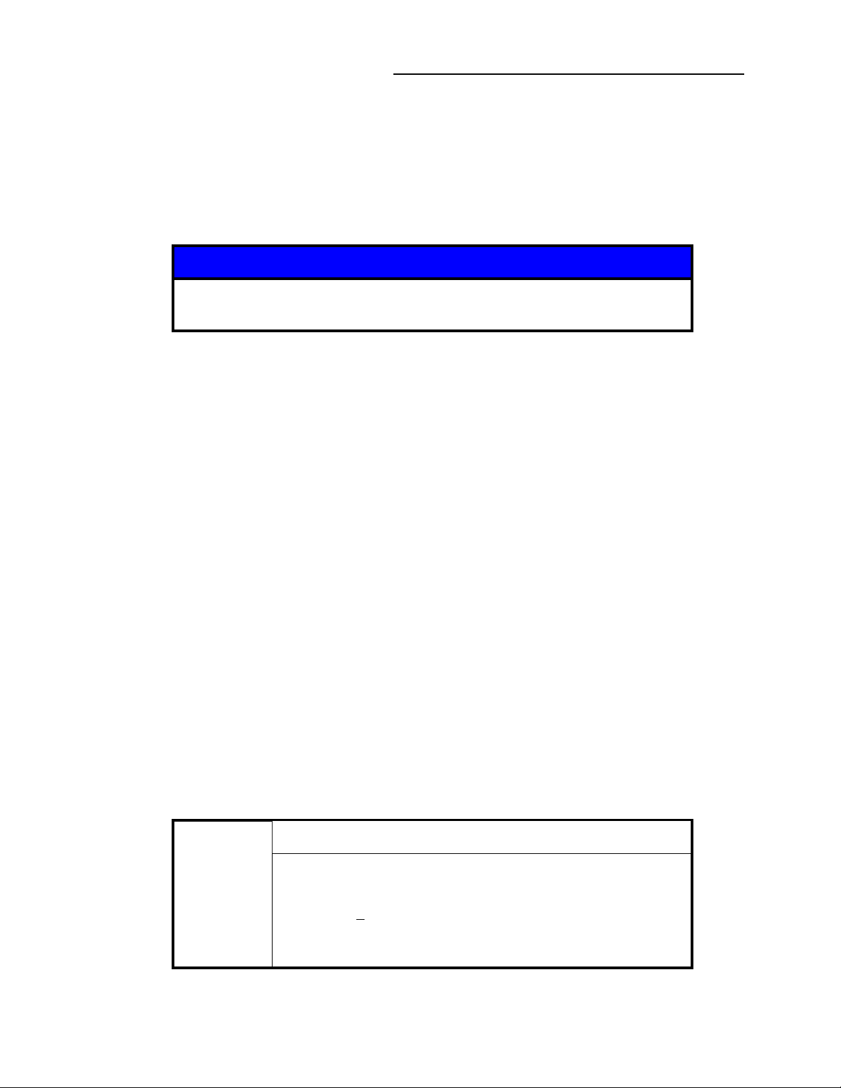
Danger indicates a hazardous situation which, if not
avoided, will result in death or serious injury.
Warning indicates a hazardous situation which, if not
avoided, could result in death or serious injury.
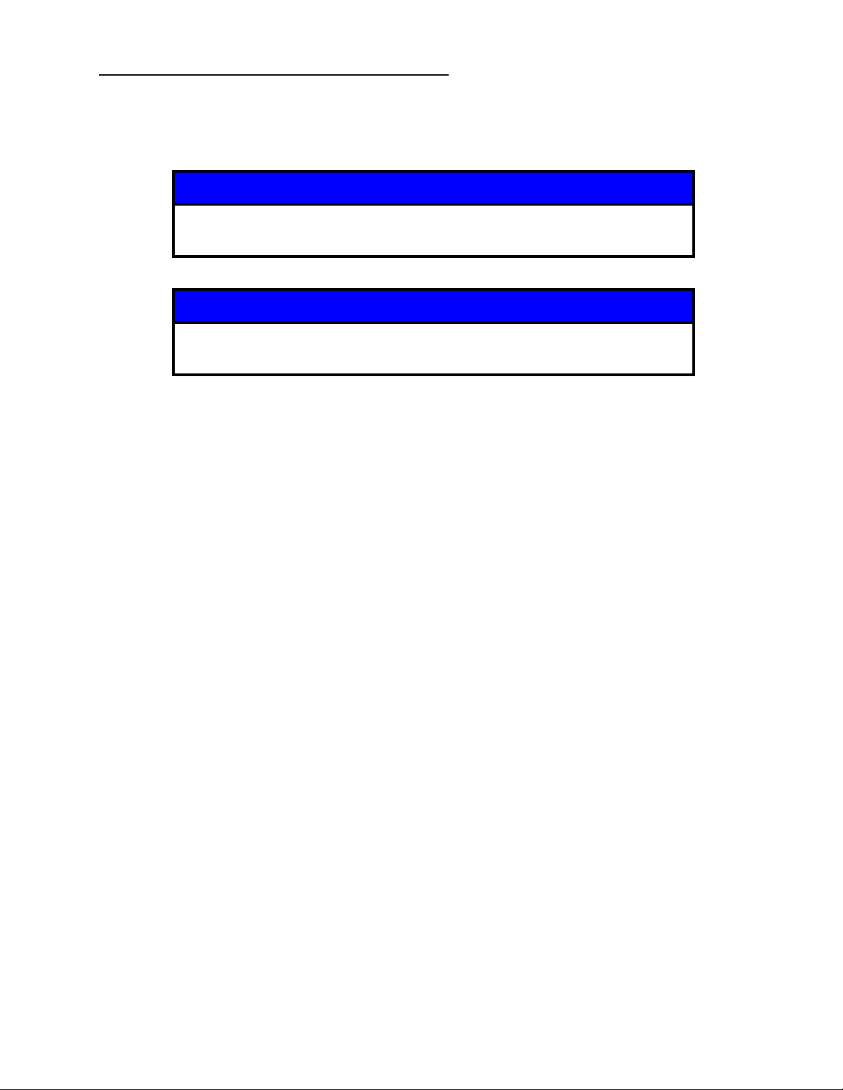
Caution indicates a hazardous situation or unsafe
practice which, if not avoided, may result in minor or
moderate personal injury.
Indicates a situation or unsafe practice which, if not
avoided, may result in equipment damage.
Notice
These instructions do not and cannot provide for every contingency that
may arise in connection with the installation, operation, or maintenance of
this product. If you require further assistance, contact MKS, GranvillePhillips Division at the address on the title page of this instruction manual.
This product was designed and tested to offer reasonably safe service provided it is installed,
operated, and serviced in strict accordance with these safety instructions.
Safety Precautions
Failure to comply with these instructions may result in serious
personal injury, including death, or property damage.
Always observe and follow all safety notices that are
provided throughout this instruction manual and on the
product.
Series 500 Cold Cathode Gauge
Instruction Manual - 500001
11
2 Safety
These safety precautions must be observed during all phases of operation, installation, and service
of this product. Failure to comply with these precautions or with specific warnings elsewhere in this
manual violates safety standards of design, manufacture, and intended use of the instrument. MKS
Instruments, Inc./Granville-Phillips disclaims all liability for the customer's failure to comply with
these requirements.
• Read Instructions – Read all safety and operating instructions before operating the product.
• Retain Instructions – Retain the Safety and Operating Instructions for future reference.
• Heed Warnings – Adhere to all warnings on the product and in the operating instructions.
• Follow Instructions – Follow all operating and maintenance instructions.
• Accessories – Do not use accessories not recommended in this manual as they may be
hazardous.
Electrical Shock or Personal Injury
The service and repair information in this manual is for the use
of Qualified Service Personnel. To avoid possible electrical
shock or personal injury, do not perform any procedures in
this manual or perform any servicing on this product unless
you are qualified to do so.
Electrical Shock or Fire
To reduce the risk of fire or electric shock, do not expose this
product to rain or moisture.
Objects and Liquid Entry - Never push objects of any kind into
this product through openings as they may touch dangerous
voltage points or short out parts that could result in a fire or
electric shock. Be careful not to spill liquid of any kind onto the
products.
2.2 Magnets
The Series 500 Cold Cathode Gauge assembly contains a very strong rare-Earth magnet assembly.
Keep it away from magnetic storage material, pacemakers, credit cards, metal objects, or any
material sensitive to magnetic fields. Care and caution must be used when handling, installing,
removing or storing the magnets as they may attract metal objects or damage material sensitive to
magnetic fields.
12
Series 500 Cold Cathode Gauge
Instruction Manual - 500001
2 Safety
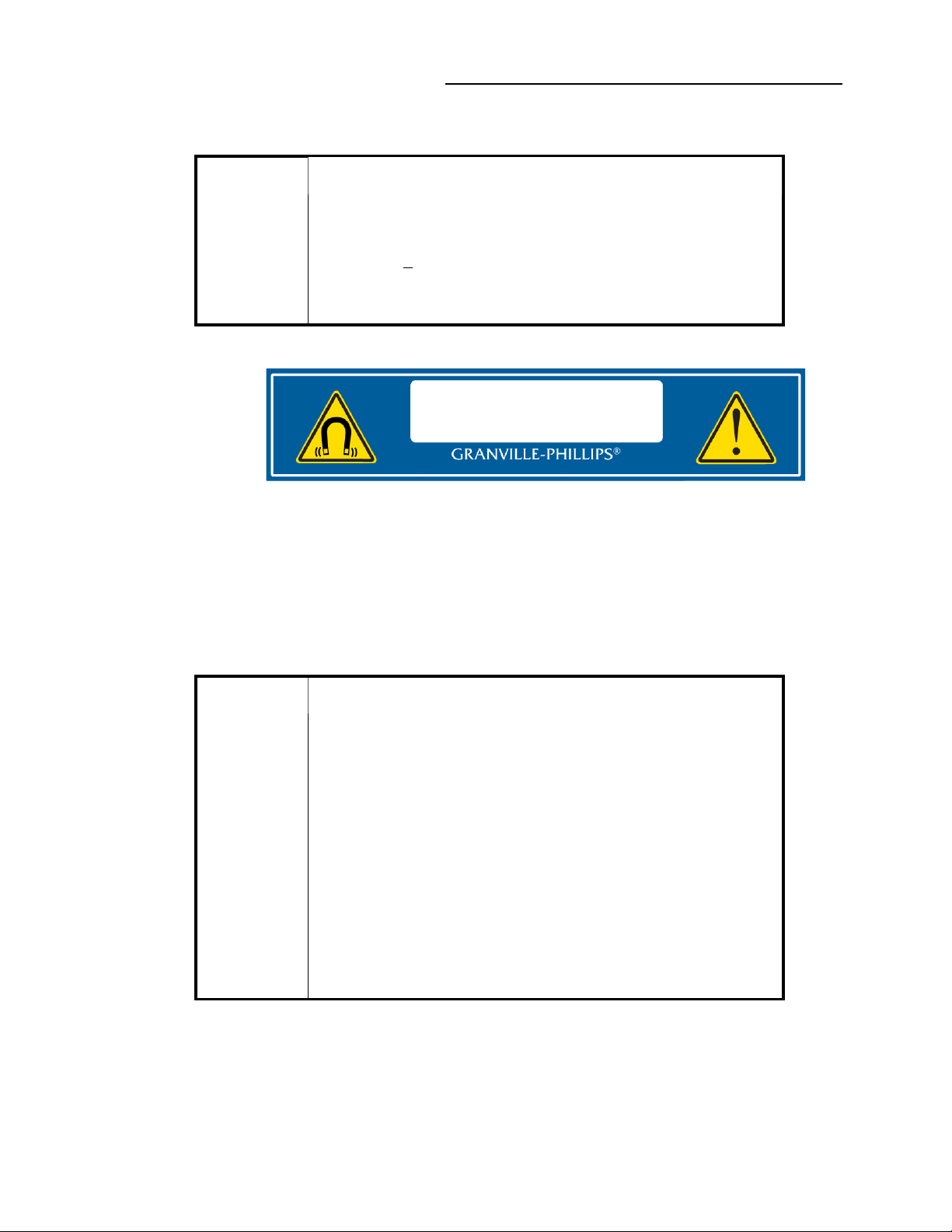
The following Safety Warning is used throughout this instruction manual where exposure to the
magnet assembly could possibly affect persons that are subject to the effects of magnets.
Strong Magnetic Field
Strong magnetic fields can disturb electronic devices like heart
pacemakers, or can impair their function. Maintain a safe
distance of >
pacemaker.
Keep tools and other metallic objects away from the magnet.
10 cm between the magnet and a heart
Figure 2-1: Magnet Assembly and Product Label
2.3 Grounding Requirements
See Grounding, Section 4.2 in the Installation chapter for more detailed requirements regarding
gauge and system grounding.
Proper Grounding
All components of a vacuum system used with this or any
similar high voltage product must be maintained at Earth
ground for safe operation.
Be aware that grounding this product does not guarantee that
other components of the vacuum system are maintained at
Earth ground.
Verify that the vacuum port to which the Series 500 Cold
Cathode Gauge is mounted is electrically grounded. It is
essential for personnel safety as well as proper operation that
the envelope of the gauge be connected to a facility ground.
See Section 4.4 for detailed grounding instructions.
Connect power cords only to properly grounded outlets or
sources.
Series 500 Cold Cathode Gauge
Instruction Manual - 500001
13
2 Safety
2.4 High Voltage
High Voltage is present in the unit when the electronics enclosure is connected to the Cold Cathode
Gauge, powered ON, and the HV ON/OFF LED is flashing or steady green. Hazardous voltages
may still be present in the module for some time after disconnecting power to the electronics
enclosure. Refer to the Installation and Service chapters for more information.
High Voltage
Be aware that when high voltage is present in any vacuum
system, a life threatening electrical shock hazard may exist
unless all exposed conductors are maintained at Earth ground.
This hazard is not unique to this product.
High Voltage
All conductors in, on, or around the vacuum system that are
exposed to potential high voltage electrical discharges must
either be shielded at all times to protect personnel or must be
connected to Earth ground at all times.
High Voltage
Be aware that an electrical discharge through a gas may
couple dangerous high voltage directly to an ungrounded
conductor almost as effectively as would a copper wire
connection. A person may be seriously injured or even killed
by merely touching an exposed ungrounded conductor at high
potential.
This hazard is not unique to this product.
2.5 Over Pressure Conditions
Notice
These instructions do not and cannot provide for every contingency that
may arise in connection with the installation, operation, or maintenance of
this product. If you require further assistance, please contact MKS,
Granville-Phillips Division at the address on the title page of this instruction
manual.
Suppliers of pressure relief valves and pressure relief disks can be located via an online search, and
are listed on ThomasNet.com under “Relief Valves” and “Rupture Discs. Confirm that these safety
devices are properly installed before installing and operating the product.
14
Series 500 Cold Cathode Gauge
Instruction Manual - 500001
Ensure the following precautions are complied with at all times:
(1) the proper gas cylinders are installed
(2) the gas cylinder valve positions are correct on manual systems
(3) the automation is correct on automated gas delivery systems
Vacuum gauges with compression fittings may be forcefully ejected if the vacuum system is
pressurized.
2.6 System and Environment
Explosive Environment
Do not use the Series 500 Cold Cathode Gauge in an
environment of explosive or combustible gases or gas
mixtures. Operation of any electrical instrument in such an
environment constitutes a definite safety hazard. Do not use
the product to measure the pressure of explosive gases or gas
mixtures.
2 Safety
Chemical Fumes / Explosive Environment
The fumes from solvents such as trichloroethylene,
perchloroethylene, toluene, and acetone can be dangerous to
health if inhaled. Use only in well ventilated areas exhausted
to the outdoors.
Acetone and toluene are highly flammable and should not be
used near an open flame or energized electrical equipment.
Potential Automatic Operation
It is the installer's responsibility to ensure that the automatic
signals provided by the product are always used in a safe
manner. Carefully check the system programming before
switching to automatic operation.
Vacuum Chamber High Pressures
Where an equipment malfunction could cause a hazardous
situation, always provide for fail-safe operation. As an
example, in an automatic backfill operation where a
malfunction might cause high internal pressures, provide an
appropriate pressure relief device.
Series 500 Cold Cathode Gauge
Instruction Manual - 500001
15
2 Safety
2.7 Safety Interlocks
Safety interlocks protect personal safety.
High Voltage
Do not attempt to defeat the safety interlock that disables the
high voltage when the electronics and sensor are not
assembled together.
High voltage is supplied to the gauge during operation.
The 500 Series Cold Cathode Gauge electronics are designed with a safety interlock to prevent
activation of the high voltage supply until the cold cathode sensor is installed in the electronics
enclosure. A gauge detection circuit is internal to the electronics enclosure.
During installation or maintenance of the Cold Cathode Gauge, it is important to fully engage the
interlock to allow the electronics to operate the gauge. See Section 4.2.3 and Section 8.3 for
detailed instructions regarding the safety interlock.
2.8 Responsibility
It is the responsibility of the Customer to comply with all local, state, and federal ordinances,
regulations, and laws applicable to the installation, operation and service of this equipment.
It is the responsibility of the end user to provide sufficient lighting at work to meet local regulations.
Operation and Service of this equipment in strict accordance with the methods and procedures
supplied by MKS, Granville-Phillips Division is the responsibility of the Customer.
MKS Instruments, Inc. assumes no liability, whatsoever, for any personal injuries or damages
resulting from the operation or service of this equipment in any manner inconsistent or contrary to
the methods supplied in Granville-Phillips literature including, but not limited to, manuals,
instructions, bulletins, communications, and recommendations.
For emergencies and for product safety related matters, contact the MKS, Granville-Phillips Division
Customer Service Department. See Section 1.5 or Section 8.4 for detailed information regarding
how to contact MKS, Granville-Phillps Division Customer Service Representatives.
2.9 Damage Requiring Service
Disconnect the product from all power sources and refer servicing to Qualified Service Personnel
under the following conditions:
a. When any cable or plug is damaged.
b. If any liquid has been spilled onto, or objects have fallen into the product.
c. If the product has been exposed to rain or water.
d. If the product does not operate normally even if you follow the operating instructions.
Adjust only those controls that are covered by the operation instructions. Improper
adjustment of other controls may result in damage and will often require extensive work
by a qualified technician to restore the product to its normal operation.
16
Series 500 Cold Cathode Gauge
Instruction Manual - 500001
2 Safety
If the product has been dropped or the enclosure has been damaged.
e.
f. When the product exhibits a distinct change in performance. This indicates a need for
service.
Notice
Do not substitute parts or modify the instrument.
Because of the danger of introducing additional hazards, do not install
substitute parts or perform any unauthorized modification to the product.
Return the product to a service facility designated by Granville-Phillips for
service and repair to ensure that safety features are maintained. Do not use
this product if it has unauthorized modifications.
Notice
Safety Check - Upon completion of any service or repairs to this product,
ask the Qualified Service Person to perform safety checks to determine that
the product is in safe operating order.
Notice
Finite Lifetime - After ten years of normal use or even non-use, the electrical
insulation in this product may become less effective at preventing electrical
shock. Under certain environmental conditions which are beyond the
manufacturer’s control, some insulation material may deteriorate sooner.
Therefore, periodically inspect all electrical insulation for cracks, crazing, or
other signs of deterioration. Do not use if the electrical insulation has
become unsafe.
See Service Guidelines, Section 1.5 for detailed information regarding how to contact MKS,
Granville-Phillps Division Customer Service Representatives.
Series 500 Cold Cathode Gauge
Instruction Manual - 500001
17

2 Safety
Notes:
18
Series 500 Cold Cathode Gauge
Instruction Manual - 500001

3 Introduction
Chapter 3
3Introduction
3.1 General Description
The Series 500 Cold Cathode Gauge (CCG) Module, shown on page 2 and in Figure 3-1, is a
modular instrument consisting a cold cathode gauge and electronics enclosure capable of
measuring vacuum pressures from 1 x 10
Benefits of the design include:
• Compact, Convenient, Cost Saving Vacuum Measurement
• No hot filament, eliminating filament burnout
• Designed for simple disassembly and cleaning or replacement of key components
• Cool, low-power operation
• Easily removable electronics and magnets for bake out
• Optional Digital I/O or optional RS-485 compatibility with computer controlled processes
• USB service port interface for offline programming and diagnostics download
-9
Torr to 1 x 10⁻² Tor r.
• An internal guard ring provides longer life by reducing contamination on critical components
and isolating leakage current from the measurement.
• Field emission starter provides faster and more predictable start times.
• Lifetime reading that indicates when gauge maintenance is needed.
The RS-485 digital interface version provides industry-standard digital RS485 communications over
networks as well as direct connections to a personal computer. The setpoint relays can be easily
controlled via the RS-485 digital interface.
The setpoint relays can be used to control various devices such as safety interlock, valve, digital
input for a scanner, or programmable logic controller. The setpoint relay trip points can be set to
customized pressure settings to turn power ON or OFF to the appropriate device.
3.2 Intended Use
The intended use of this instrument is to measure vacuum pressure in the range of 1 x 10⁻⁹ Torr
to 1 x 10
manual.
-2
Torr. This device is to be used only in accordance with the instructions in this operation
3.2.1 Improper Use
• Removal of any factory installed components.
• Modifying any factory installed components.
• Removal of any labeling or warranty seals.
• Using any of the individual components outside the Series 500 Cold Cathode Gauge.
• Operation of this device in any condensing vapor or liquid.
• CE Conformity: The manufacturer’s declaration becomes invalid if the operator modifies the
original product or installs additional components.
Series 500 Cold Cathode Gauge
Instruction Manual - 500001
19

3 Introduction
3.3 Transportation
• Reuse the original shipping container.
• Replace all of the dust caps on all ports prior to shipping.
3.4 Storage
• Store the CCG Module assembly indoors between -25 0C and 55 0C.
• Bag the CCG Module assembly in a sealed or shrink wrapped bag with desiccant.
• All of the components should be bagged and boxed together along with the instructions for
future reference.
3.5 Specifications
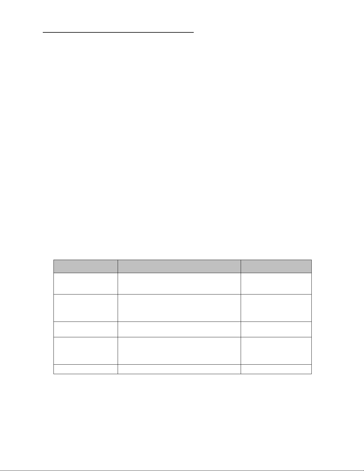
Table 3-1 Specifications for the Series 500 CCG Modules
Parameter Specification
Measurement Range for N2 / Air
1,2
Tor r
mbar
pascal
Accuracy - standard (typical)
Accuracy - calibrated gauge
Repeatability - (typical)
Display Vacuum Fluorescent
Update rate Every 0.5 sec.
Input power
Weight
3, 4
4
Operating temperature
Operation humidity
Non-operating temperature
Gauge bake out temperature with
magnet and electronics removed
Mounting orientation Any. However, avoid mounting the gauge directly below the
CE Compliance
EMC EN61326-1
Safety EN61010-1
Environmental RoHS and REACH
Setpoint relays Two, single-pole, double-throw (SPDT)
Contact rating 1 A @ 30 Vdc, Min. 5ma at 5 Vdc, max. ripple 1 Vpp
RS-485 Communication Interface
See notes 1 and 2, below
-10
1x10
1.33x10
1.33x10
to 1x10⁻² Tor r (UHV #500501: 5x10
-10
to 1.33x10⁻² mbar (UHV #500501: 6.67x10
-8
to 1.33 pa (UHV #500501: 6.67x10⁻⁹)
+/- 30% (1x10
+/- 10% (1x10
+/- 5% (1x10
-8
to 1x10⁻⁴ Torr )
-8
to 1x10⁻⁴ Torr )
-8
to 1x10⁻⁴ Torr )
-11
)
-11
13.5 to 36 Vdc, 2 W continuous (see note 3, below)
652 gr. (23 oz.)
o
0
C to +50 oC (32 0F to 122 0F) ambient, indoor use only,
ordinary protection from moisture
0 to 90% (accuracy may be affected below 1x10
o
-40
C to +70 oC (-40 0F to 158 0F)
o
250
C maximum (482 0F)
-8
Torr )
chamber to prevent sputtered material or other debris falling into
the gauge.
)
20
Series 500 Cold Cathode Gauge
Instruction Manual - 500001
3 Introduction
Table 3-1 Specifications for the Series 500 CCG Modules
Parameter Specification
Data format ASCII, software selectable:
8 bits, no parity, 1 stop bit
8 bits, even parity, 1 stop bit
8 bits, odd parity, 1 stop bit
Baud rate Software selectable, 1200 to 115200
Analog output signal
Output voltage (log) 0 to 11 Vdc
Min. output impedance 200 Ohm
Min. load impedance 10k Ohm
Min. update rate 40 Hz
Analog input signal 0 to 11 Vdc
Overpressure protection Internal and/or external at upper pressure limit
Materials exposed to gas 304 Stainless Steel, 17-7 stainless steel, ceramic, Ag/Cu brazing
material, Kovar, alumina, and molybdenum
Specifications and dimensions are subject to change without notice.
1. Measurements will change with different gases and mixtures. Correction parameters must be used for gases
other than N2 or Air.
2. Do NOT use Cold Cathode Gauges with flammable or explosive gases. See Section 2.6.
3. The 13.5 to 36 Vdc input power must be supplied from a power supply certified to IEC Standard with a
safety extra low voltage certified output.
4. RS-485 version - other versions may vary slightly.
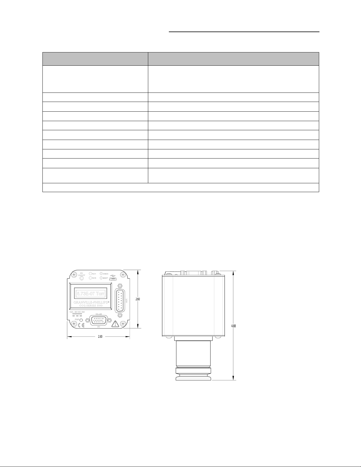
3.5.1 Dimensions
Figure 3-1: Series 500 Cold Cathode Module Dimensions
Series 500 Cold Cathode Gauge
Instruction Manual - 500001
21
3 Introduction
Note: RS-485
version shown
3.6 Electronics Enclosure
The control panel of the Series 500 Cold Cathode Module with optional RS-485 Digital Interface is
shown in Figure 3-2 and described in the following paragraphs.
Figure 3-2: Cold Cathode Module Control Panel
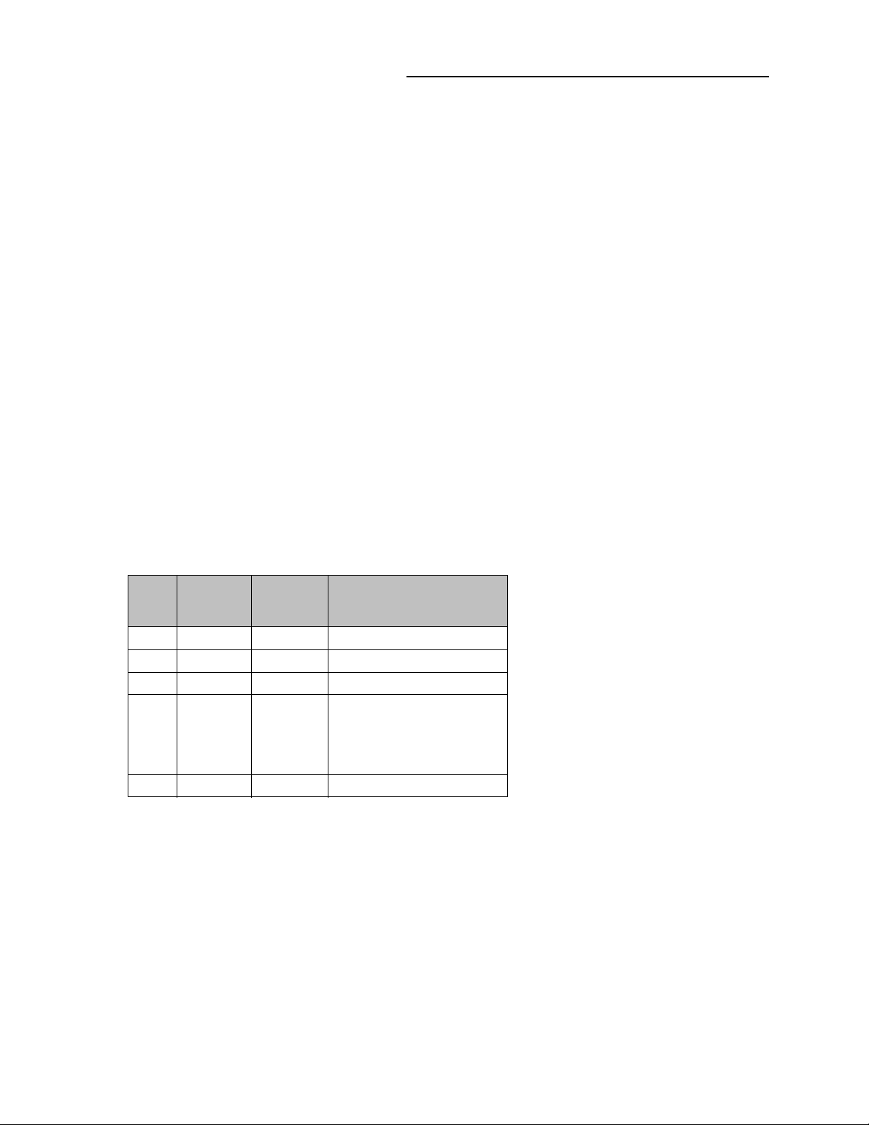
3.6.1 Control Panel LEDs
Table 3-2: Control Panel LED
Feature Conditions Color/Behavior
HV (High Voltage)
ON/OFF Button and
LED
Power LED +24V input power applied, running POST
Check LED Error/Fault condition
Maint LED Maintenance report generated (relay count,
RLY 1 or RLY 2 Relay 1 or 2 is active Solid Green
HV ON, no discharge current
HV ON, Discharge current detected
No HV ON
+24V ON, diagnostics complete
Input power OFF or below range or USB
power only
No diagnostic report present
dosing, leakage current)
Service report generated
No diagnostic report present
Blinking Green
Solid Green
OFF
Blinking Green
Solid Green
OFF
Green
OFF
Amber
Red
OFF
22
Series 500 Cold Cathode Gauge
Instruction Manual - 500001
3 Introduction
3.6.2 Input/Output Connectors
The Input/Output Connectors provide connection to the CCG Module assembly for input power
and various gauge signals. See Section 4.3 and Section 10.1for detailed pin assignments and
connection information.
3.6.3 USB Service Port
The Micro-AB socket is capable of accepting both Micro-A and Micro-B plugs. Standard operating
mode will be as a USB Slave device.
The CCG electronics enclosure can be powered through the USB Service Port when connected to a
PC for setup and diagnostics. When powered by only USB, the gauge will not be operational and
does not need to be attached to the controller.
Figure 3-3: Micro AB USB Port
Table 3-3: Micro USB Pin Connections
Pin
#
1Vdc Red +5 Vdc
2 D White Data -
3 D Green Data +
4 ID Mode Detect. May be N/
5 Gnd Black Ground
Name
Cable
Color
Description
C, GND or used as an
attached device presence
indicator (shorted to GND
with resistor)
Series 500 Cold Cathode Gauge
Instruction Manual - 500001
23

3 Introduction
Notes:
24
Series 500 Cold Cathode Gauge
Instruction Manual - 500001
4 Installation
Chapter 4
4Installation
4.1 Introduction
This section provides the information required to install the Series 500 Cold Cathode Gauge (CCG)
assembly on a vacuum system and prepare the product for use.
Notice
Disconnect all cables and sources of power from the Cold Cathode Gauge
(CCG) electronics prior to installation or maintenance.
Terms used in this chapter
• CCG Module = The Series 500 Cold Cathode Gauge Assembly - consisting of the gauge
(sensor), the magnet, and the electronics.
• CCG Gauge = the cold cathode gauge (sensor).
• CCG Electronics = the extruded aluminum enclosure that houses the electronics and firmware
for the CCG Module assembly.
• GP Connect = the software application provided with the CCG product.
4.2 Vacuum Gauge Connection (mechanical)
Use the following procedure to install the Cold Cathode Gauge on the vacuum system.
Strong Magnetic Field
Strong magnetic fields can disturb electronic devices like heart
pacemakers, or can impair their function. Maintain a safe
distance of >
pacemaker.
Keep tools and other metallic objects away from the magnet.
10 cm between the magnet and a heart
Series 500 Cold Cathode Gauge
Instruction Manual - 500001
25
4 Installation
Notice
Install the gauge on the vacuum chamber where it is protected from
physical damage and high heat.
Notice
See Section 2.5, Over Pressure Conditions, and Section 2.6, System and
Environment, for important safety information before mounting the gauge.
4.2.1 Mounting Location and Orientation
The Series 500 CCG Module can be mechanically mounted anywhere on the vacuum system in any
attitude. It should be mounted in a location with free air flow and ambient temperature less than 50
0
C (122 0F). The gauge is mounted to the vacuum system by the flange only. Be sure to use common
vacuum practices when mounting the gauge on the vacuum system.
Care should be taken when mounting near any other device that may be sensitive to magnetic fields
such as, hot cathode gauges, residual gas analyzers (quadrupoles), mag-lev turbo pumps. The
double inverted design of the Cold Cathode Gauge has a low external magnetic field, however it is
up to the user to determine if there is interference with another device and relocate one or the other
to a different location.
Adhere to good vacuum practices throughout the installation of the gauge onto a vacuum system.
• Locate the CCG Module assembly away from devices sensitive to magnetic fields such as
RGA's, hot cathodes and mag lev turbo pumps.
• Locate the CCG Module where it can be easily accessed.
• For greatest accuracy and repeatability, locate the CCG Module in a stable, room-temperature
environment. Ambient temperature should never exceed 50 °C (122 °F) operating, noncondensing, or 85 °C (185 °F) non-operating. Bake out temperature with the electronics and
magnet removed from the gauge is 250 °C (482 °F).
• Locate the CCG Module away from internal and external heat sources and in an area where
ambient temperature remains reasonably constant.
• Do not locate the CCG Module near the pump, where gauge pressure might be lower than
normal vacuum pressure.
• Do not locate the CCG Module near a gas inlet or other source of contamination.
• Do not locate the CCG Module where it will be exposed to corrosive gases such as mercury
vapor or fluorine.
• Do not locate the CCG Module directly below the vacuum chamber which may allow
sputtering particles or other contamination to fall into the gauge.
26
Series 500 Cold Cathode Gauge
Instruction Manual - 500001

4 Installation
Electronics Enclosure
Release Tab (shown
fully depressed)
4.2.2 Dimensions
• See Figure 3-1 in the Introduction Chapter.
4.2.3 Attach the Gauge to the Vacuum Chamber
Connect the CCG Gauge to the vacuum system flange using the appropriate gasket and mounting
hardware.
For an NW25KF or NW40KF flange:
1. The NW##KF style flange requires a self-centering O-ring between mating flanges. Use a metal
clamp and tighten the clamp to compress the mating flanges together. Do Not use a plastic
clamp. See Grounding in Section 4.4.
2. Attach the CCG Gauge to the mating NW-style connector on the vacuum chamber. Use a new
seal and the appropriate tools to tighten the metal clamp.
For an NW35CF (2-3/4 inch) flange:
1. Remove the electronics enclosure and the magnet from the gauge.
a. Press the electronics module release tab on the side of the module to remove the gauge
from the electronics module. See Figure 4-1.
Figure 4-1: Remove the Electronics Enclosure from the Gauge
b. Remove the magnet assembly and store it in a safe location away from magnetic media
and metal objects, as they may be damaged by, or cause damage to the magnet.
Series 500 Cold Cathode Gauge
Instruction Manual - 500001
27

4 Installation
Gauge Tube
Latch Groove
Figure 4-2: Remove the Magnet Assembly
2. Attach the gauge to the mating 2-3/4 inch flange on the vacuum chamber. Use a new copper
seal between the flanges - do not use a previously used seal. If the flanges have leak test
grooves, be sure they are properly aligned.
NOTE: Hardware recommendations for 2-3/4 inch flanges: Granville-Phillips recommends
using new, non-magnetic, Silver plated, high-strength Stainless Steel bolts, nuts, and
flat washers for mounting the Cold Cathode Gauge to the vacuum chamber. Check the
hardware, especially the bolts, with a magnet to be sure they are non-magnetic.
It is also recommended that the bolt heads be toward the gauge, and the nuts be toward
the vacuum chamber. See Figure 4-3.
3. Finger tighten all 6 bolts.
4. Use the appropriate tools to tighten the 6 bolts. Tighten the bolts in a circular pattern (such as
1, 3, 5, 2, 6, 4, 1, 3, 5, 2, 6, 4) until the flanges are in contact. After contact, torque each bolt
to 12 lb ft.
NOTE: Granville-Phillips recommends using a 12-point socket on a calibrated torque wrench to
tighten the bolts.
28
Series 500 Cold Cathode Gauge
Instruction Manual - 500001
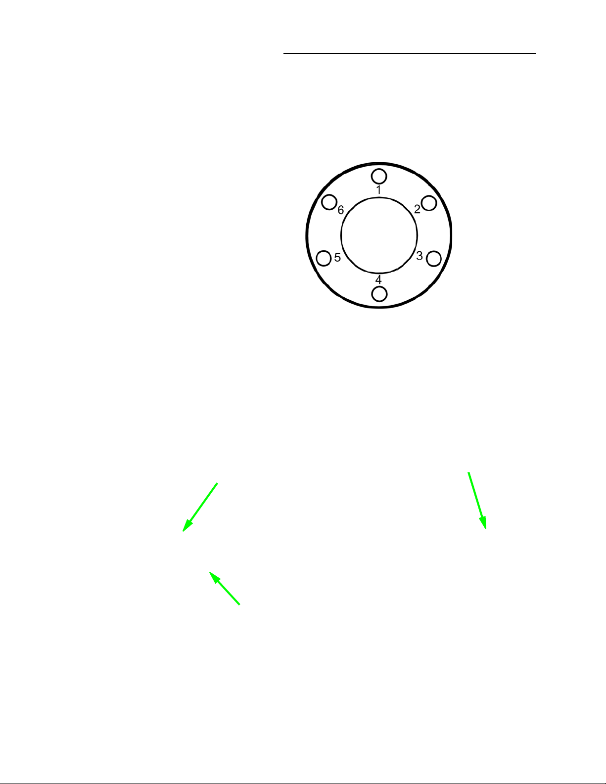
Figure 4-3: Mount the Cold Cathode Gauge to the Vacuum Chamber
Gauge Tube
Latch Groove
Alignment Hole
4 Installation
Re-assemble the CCG Module.
NOTE: During re-assembly of the module, make sure the serial numbers match for the CCG
sensor (gauge), the magnet, and the CCG electronics.
5. Install the magnet onto the gauge with the alignment hole towards the vacuum chamber, and
matched to the alignment pin on the flange. When properly aligned, the magnet will seat flush
to the flange.
Figure 4-4: Install the Magnet Assembly
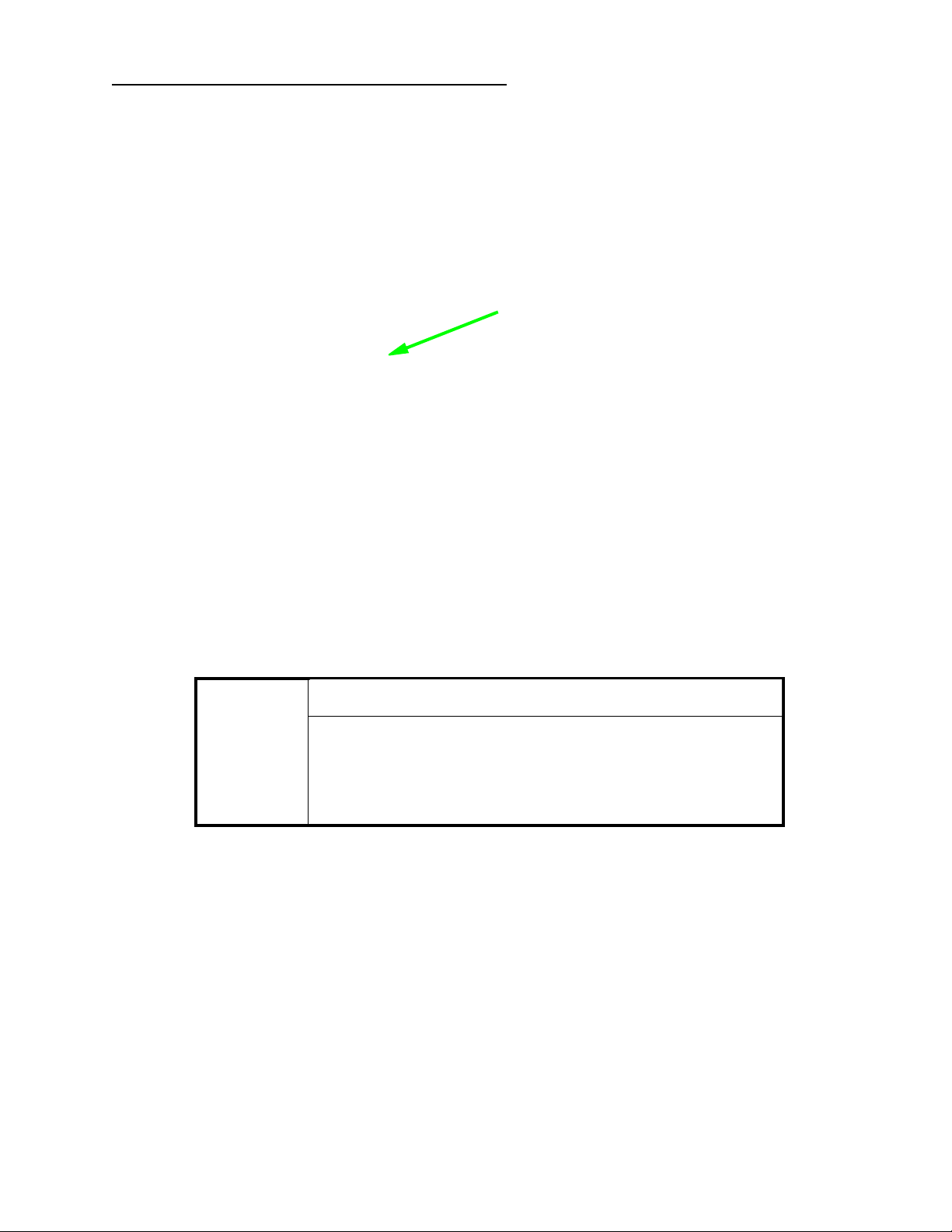
6. Re-install the electronics enclosure to the gauge by pressing in AND holding in the electronics
enclosure release tab to clear the gauge tube, then release the tab. The latch inside the
electronics enclosure will engage the latch groove on the gauge tube, locking the electronics
Series 500 Cold Cathode Gauge
Instruction Manual - 500001
29
4 Installation
Electronics Enclosure
Release Tab (shown
fully depressed)
enclosure onto the gauge. Check to make sure the electronics enclosure is fully seated by
gently pulling on the enclosure. Repeat this step if necessary and add forward pressure to
compress the gasket on the electronics enclosure.
Figure 4-5: Install the Electronics Enclosure onto the Gauge
NOTE: The gauge electronics enclosure is designed with a safety interlock that prevents the
electronics from turning ON the high voltage supply unless the gauge is fully inserted
into the electronics housing. This interlock closes an electrical contact when the gauge is
installed. To fully engage the interlock and allow the electronics to operate the gauge, it
is important to firmly and completely install the enclosure onto the gauge, making sure
the mechanical latch that holds the gauge and enclosure together is completely engaged.
Safety Interlock
High voltage is supplied to the gauge during operation. Do not
attempt to defeat the safety interlock that disables the high
voltage when the electronics and sensor are not assembled
together.
30
Series 500 Cold Cathode Gauge
Instruction Manual - 500001
 Loading...