

Granville-Phillips 475 Series Instruction Manual

Series 475
Granville-Phillips® Series 475 Convectron
Vacuum Measurement Controller
®
Instruction Manual
Instruction manual part number 475101
Revision G - January 2015

Series 475
Granville-Phillips® Series 475 Convectron
®
Vacuum Measurement Controller
This Instruction Manual is for use with all Granville-Phillips
Series 475 Vacuum Measurement Controllers. A list of
applicable catalog numbers is provided on the following page.
This product is RoHS compliant.
Customer Service/Support
For Customer Service or Technical Support 24 hours per day,
7 days per week, every day of the year including holidays:
Phone: +1-800-227-8766 or +1-303-652-4691
MKS, Granville-Phillips Division
6450 Dry Creek Parkway
Longmont, CO 80503 USA
Phone: 1-303-652-4691 or 1-800-776-6543
FAX: 1-303-652-2844
Email: gp-csr@mksinst.com
Corporate Office
MKS Instruments, Inc.
2 Tech Drive, Suite 201
Andover, MA 01810 USA
Phone: 1-978-645-5500
www.mksinst.com
Instruction Manual
© 2015, MKS Instruments, Inc. All rights reserved. Granville-Phillips® and Convectron
are registered trademarks of MKS Instruments, Inc. All other trademarks and registered
trademarks are the properties of their respective owners.
®

Granville-Phillips Series 475 Convectron
Vacuum Measurement Controller
Catalog numbers for Series 475 Convectron Vacuum Measurement Controller with Graphic Display
1/8 DIN Panel Mount or Benchtop Mount
Controller:
1/8 DIN Panel Mount or Benchtop Mount 475001 - X X - X
Interface:
None 0
RS-232 A
RS-485/422 B
Setpoints:
No setpoints 0
Two setpoints 2
Measurement Units:
Tor r T
mbar M
Pascal P
Power Supply:
Universal, CE Compliant
Power Cords:
North American 115 VAC & Japan 100 VAC 1
North American 240 VAC 2
Universal Europe 220 VAC 3
United Kingdom 240 VAC 4
475008 - X
Convectron Gauges
Gold-Plated Tungsten Sensor
275071 1/8 inch NPT / 1/2 inch compression fitting
275185 1/4 inch VCR-type female fitting
275233 3/8 inch VCO-type male fitting
275282 1/2 inch VCR-type female fitting
275256 1.33 inch (NW16CF) rotatable ConFlat-type flange
275238 2.75 inch (NW35CF) rotatable ConFlat-type flange
275203 NW16KF flange
275196 NW25KF flange
275316 NW40KF flange
Platinum Sensor
275320-PP 1/8 inch NPT, ½ inch compression fitting
275320-PQ 1/4 inch VCR-type female fitting
275320-PR 1/2 inch VCR-type female fitting
275320-PF 1.33 inch CF (NW16CF) rotatable ConFlat-type flange
275320-PG 2.75 inch CF (NW35CF) rotatable ConFlat-type flange
275320-PD NW16KF flange
275320-PE NW25KF flange
275320-PK NW40KF flange
275320-PB 15 mm OD tubulation, metric O-ring compression fitting

Table of Contents
Chapter 1 Safety & Introduction . . . . . . . . . . . . . . . . . . . . . . . . . . . . . . . . . . . . 9
1.1 Caution and Warning Statements . . . . . . . . . . . . . . . . . . . . . 9
1.2 Reading and Following Instructions . . . . . . . . . . . . . . . . . . . 9
1.3 System Grounding . . . . . . . . . . . . . . . . . . . . . . . . . . . . . . . . 10
1.4 Explosive Gases . . . . . . . . . . . . . . . . . . . . . . . . . . . . . . . . . . 10
1.5 Explosion / Implosion . . . . . . . . . . . . . . . . . . . . . . . . . . . . . . 10
1.6 Overpressure Conditions . . . . . . . . . . . . . . . . . . . . . . . . . . . 10
1.7 Operation . . . . . . . . . . . . . . . . . . . . . . . . . . . . . . . . . . . . . . . 11
1.8 Certification . . . . . . . . . . . . . . . . . . . . . . . . . . . . . . . . . . . . . 11
1.9 Extended Warranty . . . . . . . . . . . . . . . . . . . . . . . . . . . . . . . . 11
1.10 Service Guidelines . . . . . . . . . . . . . . . . . . . . . . . . . . . . . . . . 11
1.11 Damage Requiring Service . . . . . . . . . . . . . . . . . . . . . . . . . . 12
1.12 Specifications & Compliance . . . . . . . . . . . . . . . . . . . . . . . . 13
Chapter 2 Installation . . . . . . . . . . . . . . . . . . . . . . . . . . . . . . . . . . . . . . . . . . . 15
2.1 System Components . . . . . . . . . . . . . . . . . . . . . . . . . . . . . . . 15
2.2 Pre-Installation Considerations . . . . . . . . . . . . . . . . . . . . . . . 17
2.3 Installation Procedure . . . . . . . . . . . . . . . . . . . . . . . . . . . . . . 18
2.4 Install Pressure Relief Devices . . . . . . . . . . . . . . . . . . . . . . . . 18
2.5 Mount the Controller . . . . . . . . . . . . . . . . . . . . . . . . . . . . . . 18
2.6 Install the Convectron Gauge . . . . . . . . . . . . . . . . . . . . . . . . 20
Install Vacuum Chamber Fittings . . . . . . . . . . . . . . . . . . . . . 21
Ground the Convectron Gauge . . . . . . . . . . . . . . . . . . . . . . . 22
2.7 Connect the Wiring . . . . . . . . . . . . . . . . . . . . . . . . . . . . . . . 23
2.8 Connectors . . . . . . . . . . . . . . . . . . . . . . . . . . . . . . . . . . . . . . 25
2.9 Configure the Relays for the Application . . . . . . . . . . . . . . . . 26
2.10 Requirements for Process Control Option . . . . . . . . . . . . . . . 26
Chapter 3 Operation . . . . . . . . . . . . . . . . . . . . . . . . . . . . . . . . . . . . . . . . . . . . 27
3.1 Preparing for Pressure Measurement . . . . . . . . . . . . . . . . . . . 27
3.2 Button Overview . . . . . . . . . . . . . . . . . . . . . . . . . . . . . . . . . 27
3.3 Initial Power Up . . . . . . . . . . . . . . . . . . . . . . . . . . . . . . . . . . 27
3.4 Menu Overview . . . . . . . . . . . . . . . . . . . . . . . . . . . . . . . . . . 28
Product Information . . . . . . . . . . . . . . . . . . . . . . . . . . . . . . . 29
Keypad . . . . . . . . . . . . . . . . . . . . . . . . . . . . . . . . . . . . . . . . . 29
Diagnose . . . . . . . . . . . . . . . . . . . . . . . . . . . . . . . . . . . . . . . 29
Calibrate . . . . . . . . . . . . . . . . . . . . . . . . . . . . . . . . . . . . . . . . 30
3.5 Configure . . . . . . . . . . . . . . . . . . . . . . . . . . . . . . . . . . . . . . . 31
Setpoint Parameters . . . . . . . . . . . . . . . . . . . . . . . . . . . . . . . 31
RS-232 Parameters . . . . . . . . . . . . . . . . . . . . . . . . . . . . . . . . 32
RS-485/422 Parameters . . . . . . . . . . . . . . . . . . . . . . . . . . . . . 32
Analog Output . . . . . . . . . . . . . . . . . . . . . . . . . . . . . . . . . . . 33
Pressure Units . . . . . . . . . . . . . . . . . . . . . . . . . . . . . . . . . . . . 34
Display Options . . . . . . . . . . . . . . . . . . . . . . . . . . . . . . . . . . 34
Gas Species . . . . . . . . . . . . . . . . . . . . . . . . . . . . . . . . . . . . . 35
Pressure Filtering . . . . . . . . . . . . . . . . . . . . . . . . . . . . . . . . . 36
Restore Configuration . . . . . . . . . . . . . . . . . . . . . . . . . . . . . . 37
Save Configuration . . . . . . . . . . . . . . . . . . . . . . . . . . . . . . . . 37
Gauge Sensor Type . . . . . . . . . . . . . . . . . . . . . . . . . . . . . . . . 37
Series 475 Convectron Gauge Controller Instruction Manual 475101 - Rev. G 5

Table of Contents
Correction Factor Parameters . . . . . . . . . . . . . . . . . . . . . . . . 38
3.6 Error Codes . . . . . . . . . . . . . . . . . . . . . . . . . . . . . . . . . . . . . . 39
3.7 Preparing For Convectron Gauge Operation . . . . . . . . . . . . . 40
3.8 Convectron Gauge Theory of Operation . . . . . . . . . . . . . . . . 40
3.9 Convectron Gauge Sensors . . . . . . . . . . . . . . . . . . . . . . . . . . 41
3.10 Using Gases Other than N2 or Air . . . . . . . . . . . . . . . . . . . . 41
Effects on User Calibration . . . . . . . . . . . . . . . . . . . . . . . . . . 41
Indicated vs. True Pressure for Gases Other Than N
or Air . 42
2
Examples . . . . . . . . . . . . . . . . . . . . . . . . . . . . . . . . . . . . . . . 43
3.11 Calibration . . . . . . . . . . . . . . . . . . . . . . . . . . . . . . . . . . . . . . 51
Calibration Ranges for Different Gas Species . . . . . . . . . . . . 51
Vacuum Calibration . . . . . . . . . . . . . . . . . . . . . . . . . . . . . . . 51
Atmosphere Calibration . . . . . . . . . . . . . . . . . . . . . . . . . . . . 51
Convectron Gauge Use Below 10
-3
Torr . . . . . . . . . . . . . . . . 52
NIST Traceable System Calibration . . . . . . . . . . . . . . . . . . . . 52
3.12 Convectron Gauge Analog Output Signal . . . . . . . . . . . . . . . 53
Default Analog Output of 0 to 7 V . . . . . . . . . . . . . . . . . . . . 55
Optional Analog Output of 1 to 8 V . . . . . . . . . . . . . . . . . . . 55
Optional Nonlinear Analog Output “S Curve” . . . . . . . . . . . 55
3.13 Analog Output Mode Programming . . . . . . . . . . . . . . . . . . . 56
3.14 Process Control Setpoints & RS-232 or RS-485 Interface . . . . 56
Chapter 4 Process Control . . . . . . . . . . . . . . . . . . . . . . . . . . . . . . . . . . . . . . . . 57
4.1 Process Control Setup . . . . . . . . . . . . . . . . . . . . . . . . . . . . . . 57
4.2 Connecting Process Control Relays . . . . . . . . . . . . . . . . . . . . 58
4.3 Setpoint Display and Adjustment . . . . . . . . . . . . . . . . . . . . . 58
4.4 Process Control Tips . . . . . . . . . . . . . . . . . . . . . . . . . . . . . . . 59
4.5 Process Control Factory Default Settings . . . . . . . . . . . . . . . . 59
4.6 Process Control Relay Trip Points . . . . . . . . . . . . . . . . . . . . . 60
Chapter 5 RS-232 Interface . . . . . . . . . . . . . . . . . . . . . . . . . . . . . . . . . . . . . . . 61
5.1 RS-232 Theory of Operation for the 475 Controller . . . . . . . 61
5.2 Connecting the RS-232 Computer Interface . . . . . . . . . . . . . 61
5.3 RS-232 Handshake . . . . . . . . . . . . . . . . . . . . . . . . . . . . . . . . 62
5.4 Command-Response Timing . . . . . . . . . . . . . . . . . . . . . . . . . 64
5.5 Preparing the RS-232 Computer Interface . . . . . . . . . . . . . . . 64
5.6 RS-232 Command Syntax . . . . . . . . . . . . . . . . . . . . . . . . . . . 65
5.7 RS-232 Troubleshooting . . . . . . . . . . . . . . . . . . . . . . . . . . . . 75
RS-232 Error Messages . . . . . . . . . . . . . . . . . . . . . . . . . . . . . 75
Chapter 6 RS-485 Interface . . . . . . . . . . . . . . . . . . . . . . . . . . . . . . . . . . . . . . . 77
6.1 RS-485/422 Computer Interface Setup . . . . . . . . . . . . . . . . . 77
6.2 RS-485/422 Computer Interface Factory Default Settings . . . 77
6.3 RS-485/422 Computer Interface Settings . . . . . . . . . . . . . . . . 77
Baud Rate . . . . . . . . . . . . . . . . . . . . . . . . . . . . . . . . . . . . . . . 77
Data Format . . . . . . . . . . . . . . . . . . . . . . . . . . . . . . . . . . . . . 77
Address . . . . . . . . . . . . . . . . . . . . . . . . . . . . . . . . . . . . . . . . . 78
Bus Type . . . . . . . . . . . . . . . . . . . . . . . . . . . . . . . . . . . . . . . . 78
Transceiver Mode . . . . . . . . . . . . . . . . . . . . . . . . . . . . . . . . . 78
6.4 RS-485/422 Physical Configurations . . . . . . . . . . . . . . . . . . . 78
Connecting the RS-485/422 Computer Interface . . . . . . . . . . 80
6.5 Communications Protocol . . . . . . . . . . . . . . . . . . . . . . . . . . 81
6.6 RS-485/422 Command Syntax . . . . . . . . . . . . . . . . . . . . . . . 81
6.7 RS-485/422 Response Syntax . . . . . . . . . . . . . . . . . . . . . . . . 81
6 Series 475 Convectron Gauge Controller Instruction Manual 475101 - Rev. G

Table of Contents
Command Descriptions . . . . . . . . . . . . . . . . . . . . . . . . . . . . 82
6.8 Command-Response Timing . . . . . . . . . . . . . . . . . . . . . . . . . 93
6.9 RS-485 Troubleshooting . . . . . . . . . . . . . . . . . . . . . . . . . . . . 94
RS-485 Error Messages . . . . . . . . . . . . . . . . . . . . . . . . . . . . . 94
Chapter 7 Diagnostics . . . . . . . . . . . . . . . . . . . . . . . . . . . . . . . . . . . . . . . . . . . 95
7.1 Continuous Diagnostics . . . . . . . . . . . . . . . . . . . . . . . . . . . . 96
7.2 Diagnostics Requiring User Interaction . . . . . . . . . . . . . . . . . 96
Analog Output . . . . . . . . . . . . . . . . . . . . . . . . . . . . . . . . . . . 96
Measurement Circuits . . . . . . . . . . . . . . . . . . . . . . . . . . . . . . 96
7.3 Convectron Gauge Simulator . . . . . . . . . . . . . . . . . . . . . . . . 97
Simulate a Process Operation Prior to Full System Integration 97
Analog Output Tests . . . . . . . . . . . . . . . . . . . . . . . . . . . . . . . 98
Controller Calibration Verification . . . . . . . . . . . . . . . . . . . . 98
Chapter 8 Service and Maintenance . . . . . . . . . . . . . . . . . . . . . . . . . . . . . . . . . 99
8.1 Customer Service . . . . . . . . . . . . . . . . . . . . . . . . . . . . . . . . . 99
8.2 Service Guidelines . . . . . . . . . . . . . . . . . . . . . . . . . . . . . . . . 99
8.3 Damage Requiring Service . . . . . . . . . . . . . . . . . . . . . . . . . . 100
8.4 Error Codes and Possible Solutions . . . . . . . . . . . . . . . . . . . . 101
8.5 Convectron Gauge Test Procedure . . . . . . . . . . . . . . . . . . . . 103
8.6 Cleaning Contaminated Convectron Gauges . . . . . . . . . . . . . 103
8.7 Reset to Factory Defaults . . . . . . . . . . . . . . . . . . . . . . . . . . . 104
Index . . . . . . . . . . . . . . . . . . . . . . . . . . . . . . . . . . . . . . . . . . . . . . . . . . . . . . . . . . . . . 105
Series 475 Convectron Gauge Controller Instruction Manual 475101 - Rev. G 7

Table of Contents
8 Series 475 Convectron Gauge Controller Instruction Manual 475101 - Rev. G
Chapter 1 Safety & Introduction
CAUTION
WARNING
1.1 Caution and Warning Statements
This manual contains caution and warning statements with which you must
comply to prevent inaccurate measurement, property damage, or personal
injury.
Caution statements alert you to hazards or unsafe
practices that could result in minor personal injury or
property damage.
Each caution statement explains what you must do to
prevent or avoid the potential result of the specified
hazard or unsafe practice.
Warning statements alert you to hazards or unsafe
practices that could result in severe personal injury or
death due to electrical shock, fire, or explosion.
Each warning statement explains what you must do
to prevent or avoid the potential result of the
specified hazard or unsafe practice.
Each caution or warning statement explains:
1. The specific hazard that you must prevent or unsafe practice that you
must avoid,
2. The potential result of your failure to prevent the specified hazard or
avoid the unsafe practice, and
3. What you must do to prevent the specified hazardous result.
1.2 Reading and Following Instructions
Series 475 Convectron Gauge Controller Instruction Manual 475101 - Rev. G 9
You must comply with all instructions while you are installing, operating, or
maintaining the Controller. Failure to comply with the instructions violates
standards of design, manufacture, and intended use of the Controller.
Granville-Phillips and Brooks Automation disclaim all liability for the
customer's failure to comply with the instructions.
• Read instructions – Read all instructions before installing or operating the
Controller.
• Retain instructions – Retain the instructions for future reference.
• Follow instructions – Follow all installation, operating and maintenance
instructions.
• Heed warnings and cautions – Adhere to all warnings and caution
statements on the Controller and in these instructions.
• Parts and accessories – Install only those replacement parts and
accessories that are recommended by Granville-Phillips. Substitution of
parts is hazardous.

Chapter 1
WARNING
Read these safety notices and warnings before
installing, using, or servicing this equipment. If you
have any doubts regarding the safe use of this
equipment, contact the Granville−Phillips Customer
Service department at the address listed in this user
manual.
Each warning statement explains what you must do
to prevent or avoid the potential result of the
specified hazard or unsafe practice.
1.3 System Grounding Ion producing equipment, such as ionization gauges, mass spectrometers, sputtering systems, etc., from many manufacturers may, under some conditions, provide sufficient electrical conduction via a plasma to couple a high voltage electrode potential to the vacuum chamber. If exposed conductive parts of the gauge, Controller, and chamber are not properly grounded, they may attain a potential near that of the high voltage electrode during this coupling. Potential fatal electrical shock could then occur because of the high voltage between these exposed conductors and ground.
All components in a vacuum system used with this or any similar high
voltage product must be maintained at Earth ground for safe operation.
Connect power cords only to properly grounded outlets or sources.
1.4 Explosive Gases Do not use the Series 475 Controller or a Series 275 Convectron Gauge in an environment of explosive or combustible gases or gas mixtures. Operation of any electrical instrument in such an environment constitutes a definite safety hazard. Do not use the product to measure the pressure of explosive gases or gas mixtures. The sensor wire of a Convectron Gauge normally operates at 125 degrees Centigrade. If a malfunction causes the sensor wire to reach a higher temperature, it could raise the sensor wire temperature to above the ignition point of combustible materials or gases.
Danger of explosion or inadvertent venting to atmosphere exists in all
vacuum systems which incorporate gas sources or involve processes capable
of pressuring the system above safe limits.
1.5 Explosion / Implosion Danger of injury to personnel and damage to equipment exists on all vacuum systems that incorporate gas sources or involve processes capable of pressuring the system above the limits it can safely withstand.
For example, danger of explosion in a vacuum system exists during
backfilling from pressurized gas cylinders because many vacuum devices
such as ionization gauge tubes, glass windows, glass belljars, etc., are not
designed to be pressurized.
1.6 Overpressure
Conditions
Do NOT subject Series 275 Convectron Gauges to pressures above 1000
Torr.
Install suitable devices that will limit the pressure from external gas sources
to the level that the vacuum system can safely withstand. In addition, install
suitable pressure relief valves or rupture disks that will release pressure at a
10 Series 475 Convectron Gauge Controller Instruction Manual 475101 - Rev. G

Safety & Introduction
level considerably below that pressure which the system can safely
withstand.
Suppliers of pressure relief valves and pressure relief disks are listed in
Thomas Register under "Valves, Relief", and "Discs, Rupture".
Confirm that these safety devices are properly installed before installing the
Series 275 Convectron Gauge. In addition, check that (1) the proper gas
cylinders are installed, (2) gas cylinder valve positions are correct on manual
systems, and (3) the automation is correct on automated systems.
Using the N
calibration to pressurize a vacuum system above 1 Torr with
2
certain other gases can cause dangerously high pressures which can cause
explosion of the system. See Indicated vs. True Pressure for Gases Other
Than N
or Air on page 42.
2
If used improperly, Convectron Gauges can supply misleading pressure
indications that can result in dangerous overpressure conditions within the
system.
1.7 Operation It is the installer's responsibility to ensure that the automatic signals provided by the process control module are always used in a safe manner.
Carefully check manual operation of the system and the setpoint
programming before switching to automatic operation. Where an equipment
malfunction could cause a hazardous situation, always provide for fail-safe
operation. As an example, in an automatic backfill operation where a
malfunction might cause high internal pressures, provide an appropriate
pressure relief device.
1.8 Certification MKS Instruments, Inc. certifies that this product met its published specifications at the time of shipment from the factory. MKS Instruments further certifies that its calibration measurements are traceable to the National Institute of Standards and Technology to the extent allowed by the Institute's calibration facility. See the CE Declaration of Conformity inside envelope for the CE tests performed.
1.9 Extended Warranty MKS Instruments, Inc. provides an extended warranty period to five (5) years from the date of shipment for the Granville-Phillips Series 475 Controllers. The MKS Instruments, Inc. General Terms and Conditions of Sale provides the complete and exclusive warranty for Granville-Phillips products. This document is located on our web site at www.mksinst.com, or may be obtained by contacting a Granville-Phillips Customer Service Representative.
1.10 Service Guidelines Some minor problems are readily corrected on site. If the product requires service, contact the MKS, Granville-Phillips Division Customer Service Department at +1-800-227-8766 or +1-303-652-4691 for troubleshooting help over the phone.
If the product must be returned to the factory for service, request a Return
Material Authorization (RMA) from Granville-Phillips. Do not return
products without first obtaining an RMA. In some cases a hazardous
materials document may be required. The MKS/Granville-Phillips Customer
Service Representative will advise you if the hazardous materials document
is required.
Series 475 Convectron Gauge Controller Instruction Manual 475101 - Rev. G 11

Chapter 1
When returning a products to Granville-Phillips, be sure to package the
products to prevent shipping damage. Circuit boards and modules separated
from the gauge assembly must be handled using proper anti-static protection
methods and must be packaged in anti-static packaging. Granville-Phillips
will supply return packaging materials at no charge upon request. Shipping
damage on returned products as a result of inadequate packaging is the
Buyer's responsibility.
For Customer Service or Technical Support 24 hours per day, 7 days per
week, every day of the year including holidays:
Phone: +1-800-227-8766 or +1-303-652-4691
Email: gp-csr@mksinst.com
MKS, Granville-Phillips Division
6450 Dry Creek Parkway
Longmont, CO 80503 USA
Phone: 1-303-652-4691 or 1-800-776-6543
FAX: 1-303-652-2844.
1.11 Damage Requiring
Service
Turn OFF power to the Controller and refer servicing to qualified service
personnel under the following conditions:
• If any liquid has been spilled onto, or objects have fallen into the
Controller.
• If a circuit board is faulty.
• If the Convectron Gauge sensing wire is open or the gauge is
contaminated.
• If the Controller has been exposed to moisture.
• If the Controller does not operate normally even if you follow the
operating instructions. Adjust only those controls that are explained in this
instruction manual. Improper adjustment of other controls may result in
damage and will often require extensive work by a qualified technician to
restore the Controller to its normal operation.
• If the Controller has been dropped or the enclosure has been damaged.
• If the Controller exhibits a distinct change in performance.
12 Series 475 Convectron Gauge Controller Instruction Manual 475101 - Rev. G
Safety & Introduction
1.12 Specifications
& Compliance
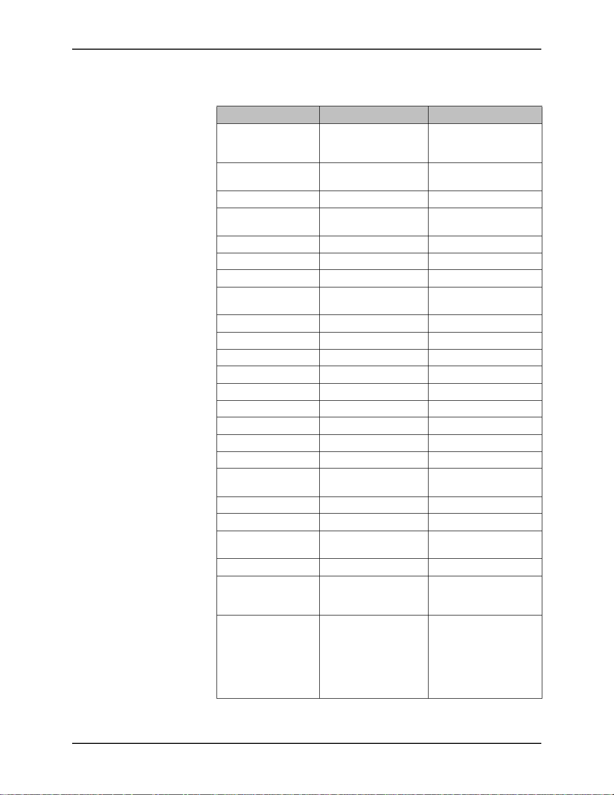
Table 1-1 Specifications & Compliance for the Series 475 Controller and 275 Convectron Gauge
Parameter Specification
Measurement Range for N2 / Air
1,2
Torr
mbar
pascal
Resolution
Display Vacuum Fluorescent
Update rate Every 0.5 sec.
Input power
3
Weight 720 gr. (25 oz.)
Operating environment
Operating conditions Suitable for continuous operation, category 1 for insulation overvoltage,
Non-operating temperature
Compliance
EMC EN61326-1
Safety EN61010-1
IP rating IP20
Environmental RoHS compliant
Setpoint relays (Optional) (2) single-pole, double-throw (SPDT) (Limit overvoltage to <2.4kv)
Contact rating 5 A @ 250 VAC resistive load
Range
Resolution 1 significant digit in the 10
Communication Interface
(Optional)
RS-232
Data format ASCII, software selectable:
Baud rate Software selectable, 1200, 2400, 4800, 9600, 14400, 19200, 28800, 38400
Hardware Handshake RTS / CTS
RS-485
Data format ASCII, software selectable:
Baud rate Software selectable, 1200, 2400, 4800, 9600, 14400, 19200, 28800, 38400
Bus type Software selectable: two-wire or four-wire configurations
Convectron Gauge
Sensor material Gold-plated tungsten, platinum
See notes 1 and 2, below
-4
to 999 Torr
1x10
-4
to 1333 mbar
1x10
-2
to 133.3 kpa
1x10
-4
Torr, 1x10⁻⁴ mbar, 1x10⁻² Pascal
1x10
12 to 24 Vdc, 6 W continuous (Inrush <1.4A for <7 msec) (see note 3, below)
o
C to 40 oC ambient, indoor use only, ordinary protection from moisture,
0
maximum altitude 3000 meters
pollution degree 2, Class 1
o
-40
C to 85 oC
-4
1x10
to 1000 Torr, 0.1 to 1333 mbar, 0.01 to 133.3 kPa
-4
range
2 significant digits in the 10
3 significant digits in the 10
-3
range
-2
range and above
"8 bits, no parity, 1 stop bit
"7 bits, even parity, 1 stop bit
"7 bits, odd parity, 1 stop bit
selectable hardware handshake
"8 bits, no parity, 1 stop bit
"7 bits, even parity, 1 stop bit
"7 bits, odd parity, 1 stop bit
Series 475 Convectron Gauge Controller Instruction Manual 475101 - Rev. G 13
Chapter 1
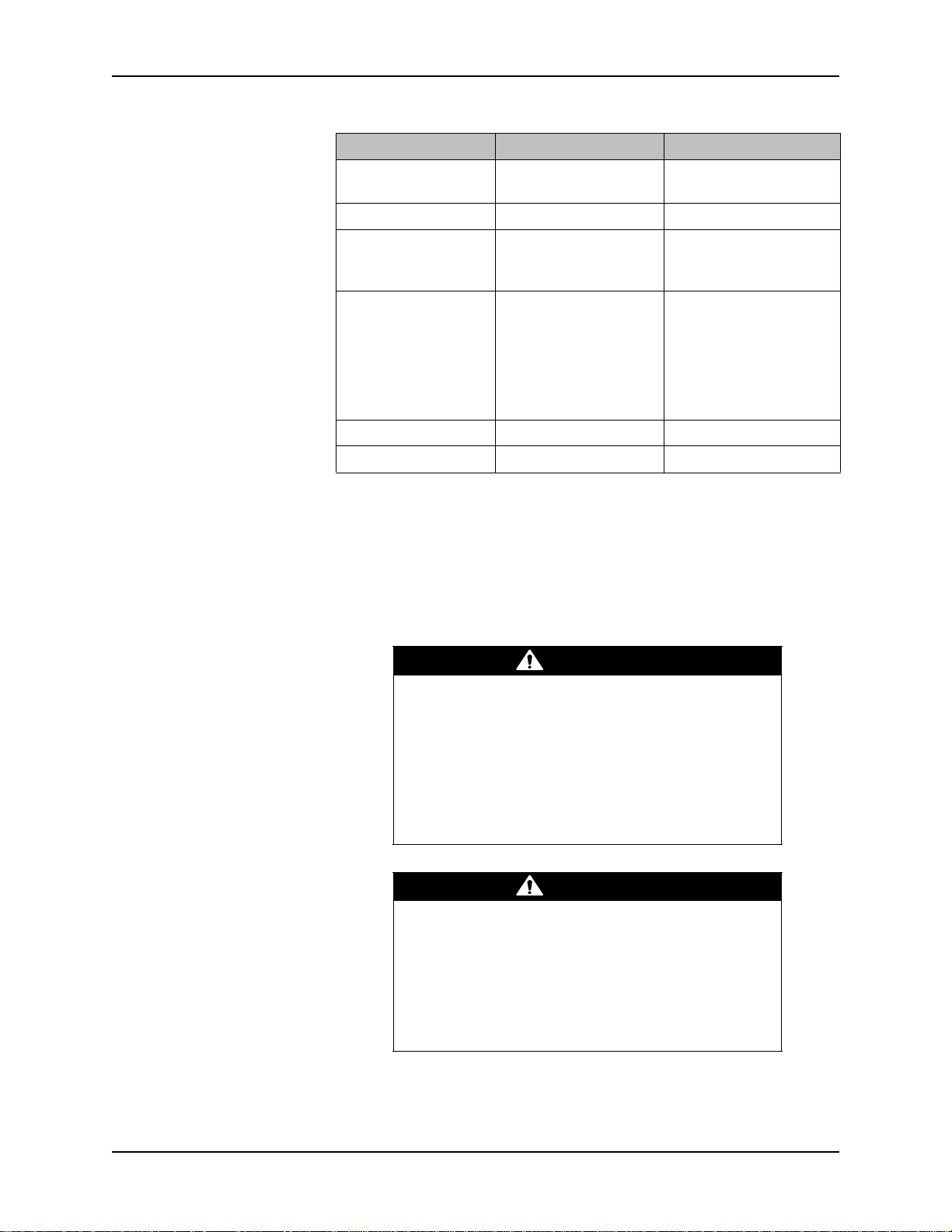
Table 1-1 Specifications & Compliance for the Series 475 Controller and 275 Convectron Gauge
Parameter Specification
Other materials exposed to gas 304 stainless steel, borosilicate glass, Kovar, alumina, NiFe alloy, polymide
Internal volume
Weight 85 gm (3 oz.)
Mounting orientation Horizontal preferred
Gauge operating temperature
Gauge bakeout temperature
Cable bakeout temperature
3
(2.5 in.3)
40 cm
o
0
C to 50 oC ambient
o
C maximum, non-operating, cable disconnected
150
o
C maximum
105
1. Measurements will change with different gases and mixtures. Correction
parameters must be used for gases other than N2 or Air.
2. Do NOT use Convectron Gauges with flammable or explosive gases. See
Section 1.4.
3. The 24 Vdc input power must be supplied from a power supply certified to
IEC Standard with a safety extra low voltage certified output.
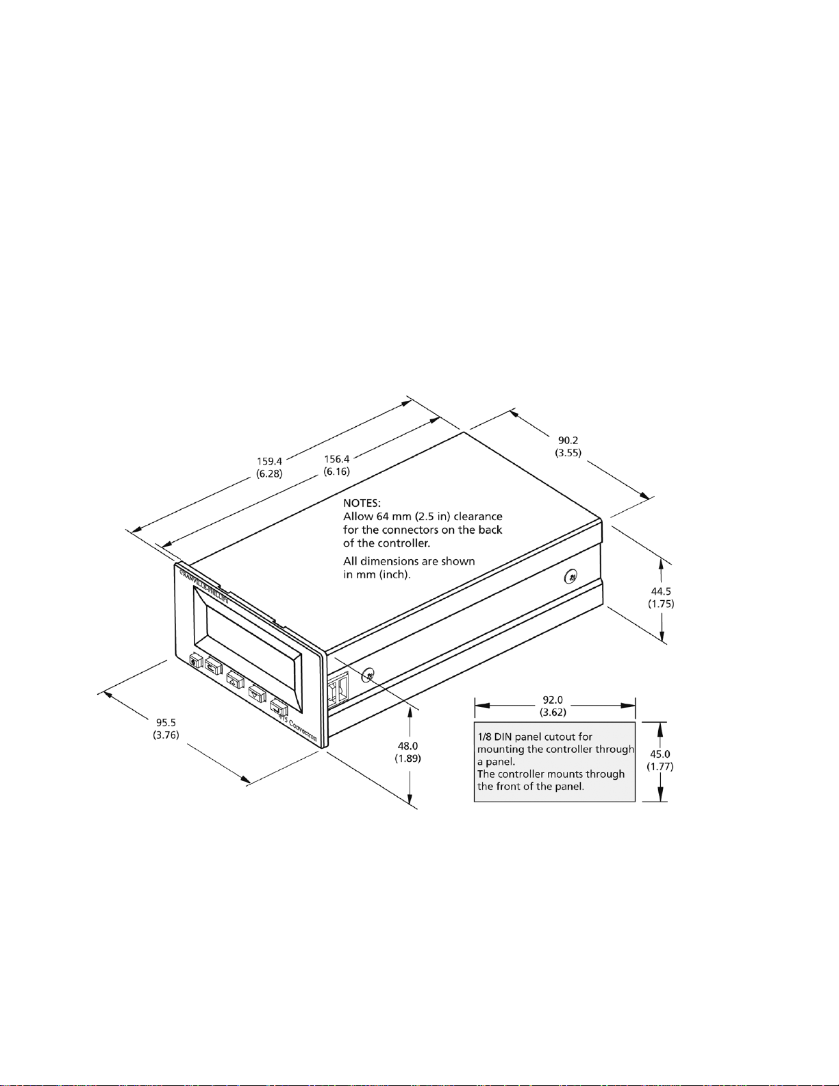
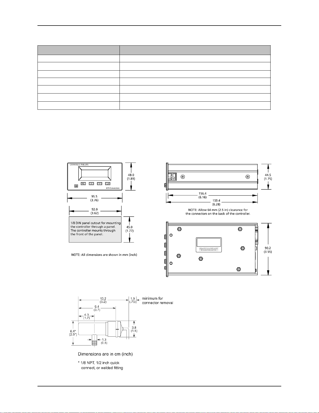
Figure 1-1 475 Convectron Gauge Controller Dimensions
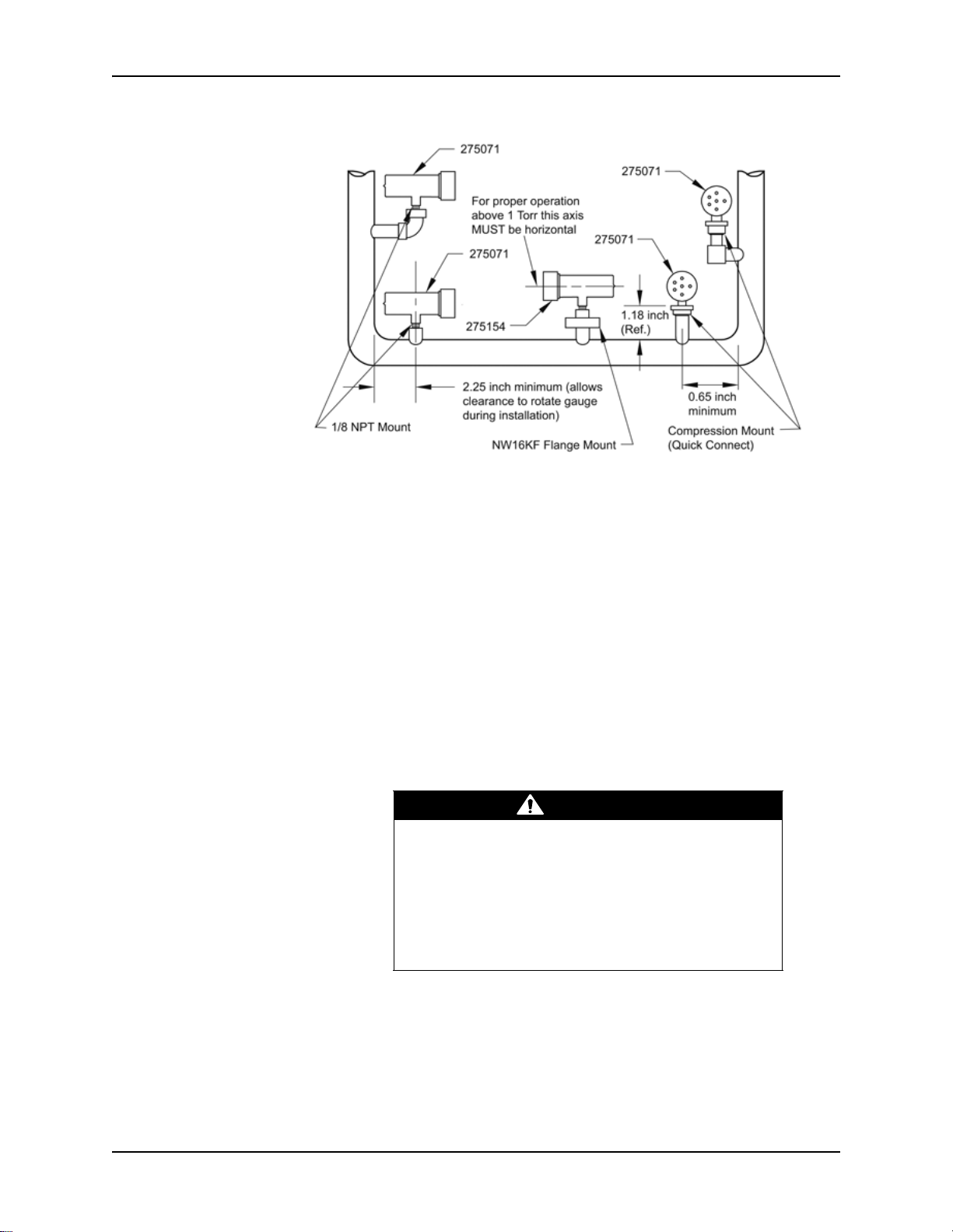
Figure 1-2 Series 275 Convectron Gauge Dimensions
14 Series 475 Convectron Gauge Controller Instruction Manual 475101 - Rev. G
Chapter 2 Installation
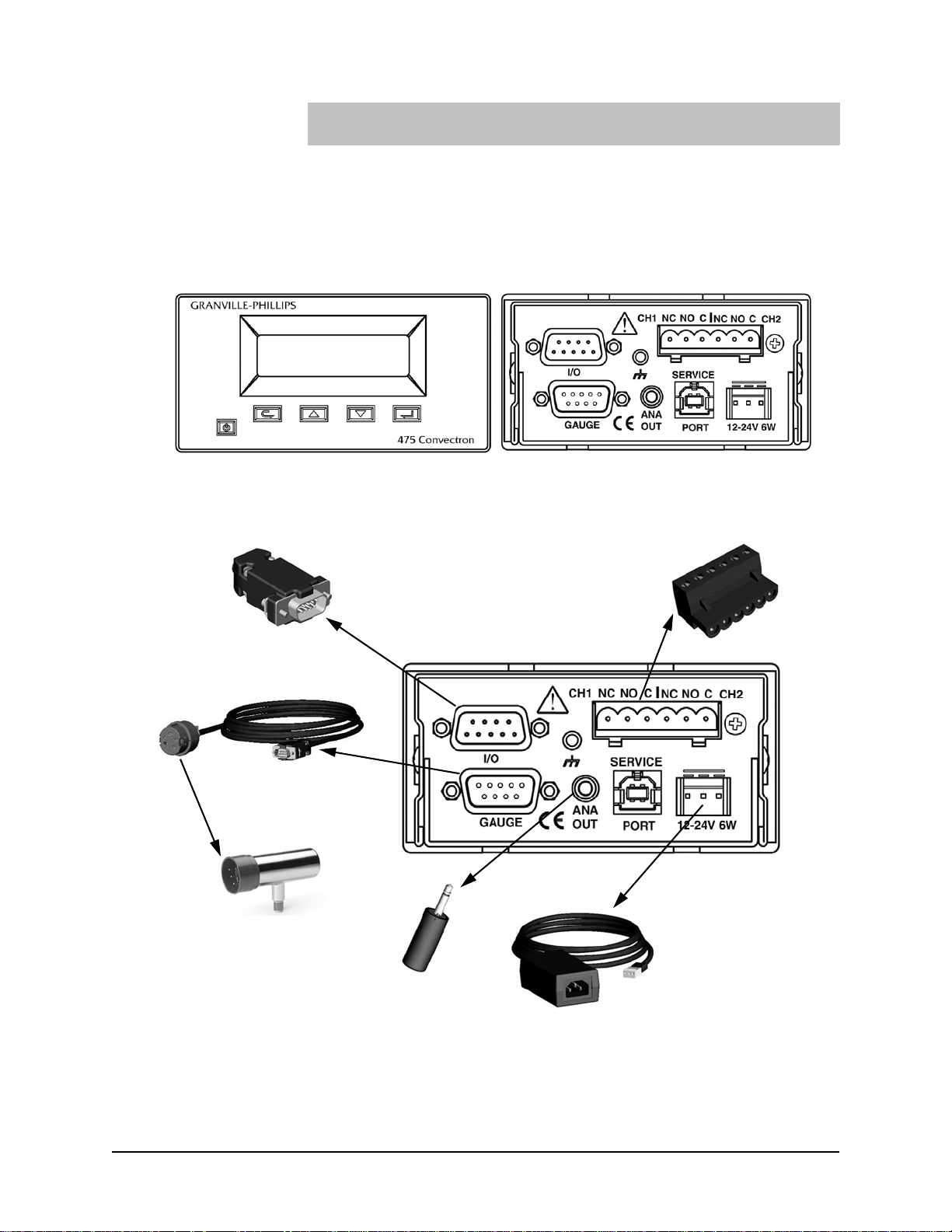
Analog output
connector
I/O output connector
2-channel process
control connector
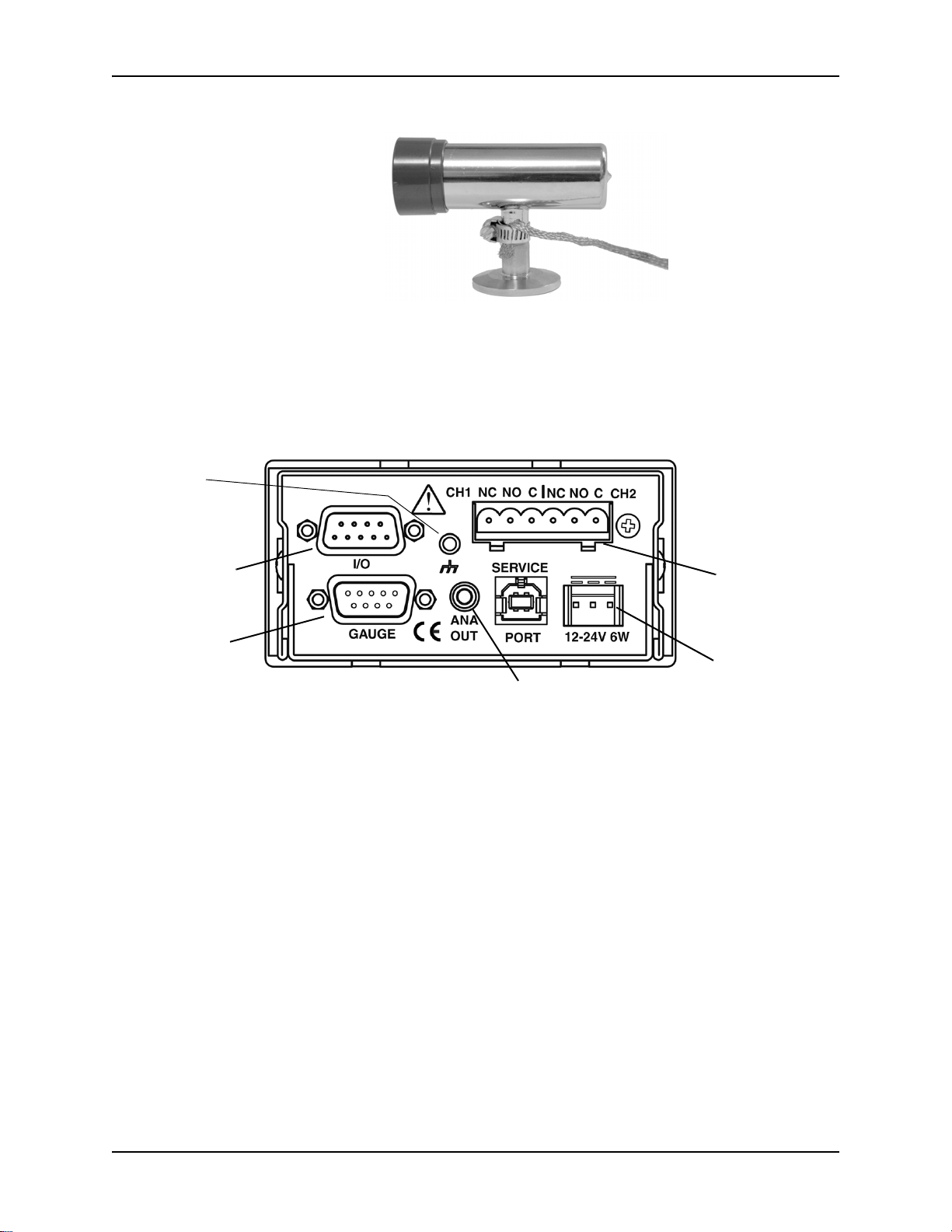
Convectron Gauge
24 Vdc power supply
cable and converter
Gauge cable
NOTE: The Service Port is
for factory use only.
2.1 System Components Figure 2-1 and Figure 2-2 illustrate all available options and system capabilities, including Controllers with process control and RS-232 or RS-485 computer interface options.
Figure 2-1 Series 475 Convectron Controller Front and Rear Panels
Figure 2-2 Convectron Vacuum Measurement System Components
Series 475 Convectron Gauge Controller Instruction Manual 475101 - Rev. G 15
Chapter 2
Table 2-1 475 Controller Factory Defaults
Setting Range or Selection Factory Default Setting
Units of Measure Torr, mbar, pascal Torr, mbar, or pascal as
selected when the
Controller was purchased.
Gas Species N
, Ar, O2, He, CO2,
2
N
2
FS, CF
Correction Factor 0.1 to 1.5 None
Correction Factor
1E-3 Torr to 999 Torr 999 Torr
Maximum Pressure
Front Panel Display
• Brightness 1, 2, or 3 3 (Bright)
• Setpoints displayed Yes, No No
Gauge Sensor Gold-Plated Tungsten,
Gold-Plated Tungsten
Platinum
SetPoints/Outputs
• SP1 Pressure 1E-4 Torr to 1000 Torr 1.00E-4
• SP2Pressure 1E-4 Torr to 1000 Torr 1.00E-4
• SP1 Hysteresis 5 to 1000 percent 10
• SP2 Hysteresis 5 to 1000 percent 10
• SP1 Polarity Normal, Reverse Normal
• SP2 Polarity Normal, Reverse Normal
• SP1 Enable Disable, Enable Disable
• SP2 Enable Disable, Enable Disable
• Analog Out Mode Log 0-7V, Log 1-8V,
Log 0 V-7 V
S-curve
• Analog Out Offset 0.0V to 5.0V 0V
Low-Pass Filter (LPF) Disable, Enable Enable
Pressure Response
0 to 200 ms 0 ms
Delay (ms)
RS-232
• Baud Rate Baud Rate: 1200, 2400,
19200 baud
4800, 9600, 14400,
19200, 28800, 38400
• Data Format Bits:
• 8N1 (8 data bits,
8 data bits, No parity, 1
stop bit
No parity, 1 stop bit)
• 7E1 (7 data bits,
Even parity, 1 stop bit)
• 7O1 (7 data bits,
Odd parity, 1 stop bit)
16 Series 475 Convectron Gauge Controller Instruction Manual 475101 - Rev. G
Installation
WARNING
WARNING
Table 2-1 475 Controller Factory Defaults
Setting Range or Selection Factory Default Setting
• Hardware
Handshake
RS-485
• Baud Rate Baud Rate: 1200, 2400,
• Data Format Bits:
• Bus Type Two-wire or four-wire Four-wire
• Transceiver Mode Fast or Slow Fast
RTS / CTS or None None
19200 baud
4800, 9600, 14400,
19200, 28800, 38400
8 data bits, No parity, 1
• 8N1 (8 data bits,
No parity, 1 stop bit)
• 7E1 (7 data bits,
Even parity, 1 stop bit)
• 7O1 (7 data bits,
Odd parity, 1 stop bit)
stop bit
2.2 Pre-Installation
Considerations
This chapter guides you through the basic setup procedures for the 475
Controller, including mounting the Controller, installing a Convectron
Gauge, connecting vacuum chamber fittings, and connecting wiring.
If your application requires different settings than the factory defaults listed
in Table 2-1, see Chapters 3, 4, and 5 for instructions on changing the
settings. You can reconfigure options before or after completing the basic
setup procedures described in this chapter.
Installing, removing, or replacing the 475 Controller
in a high-voltage environment can cause an electrical
discharge through a gas or plasma, resulting in
property damage or personal injury due to electrical
shock or fire.
Vent the vacuum chamber to atmospheric pressure
and shut OFF power to the Controller before you
install, remove, or replace the Controller.
Exposing the Controller to moisture can cause fire or
electrical shock resulting in product damage or
personal injury.
To avoid exposing the Controller to moisture, install
the Controller in an indoor environment. Do not
install the Controller in any outdoor environment. Do
not spill any liquid onto the Controller.
Series 475 Convectron Gauge Controller Instruction Manual 475101 - Rev. G 17
Chapter 2
CAUTION
2.3 Installation Procedure The Controller installation procedure includes the following steps:
1. Install the appropriate pressure relief devices in the vacuum system.
2. Establish the desired location and orientation for the Series 475
Controller.
3. Install the Convectron Gauge that connects to the Controller.
4. Assemble and connect the Controller wiring.
5. Adjust the process control relays for the process pressures that will be
used.
2.4 Install Pressure Relief Devices
2.5 Mount the Controller To locate and orient the Controller, refer to Figure 2-3 and follow the
Before you install the Controller, install appropriate pressure relief devices in
the vacuum system.
Granville-Phillips does not supply pressure relief valves or rupture disks.
Suppliers of pressure relief valves and pressure relief disks can be located via
an on-line search, and are listed on ThomasNet.com under “Relief Valves”
and “Rupture Discs. Confirm that these safety devices are properly installed
before installing and operating the product.
Operating the Controller above 1000 Torr (1333
mbar, 133 kPa) true pressure could cause pressure
measurement error or product failure.
To avoid measurement error or product failure due to
overpressurization, install pressure relief valves or
rupture disks in the system if pressure exceeds 1000
Torr (1333 mbar, 133 kPa).
instructions below.
• For greatest accuracy and repeatability, locate the Controller in a stable,
room-temperature environment. Ambient temperature should never
exceed 40 °C (104 °F) operating, non-condensing, or 85 °C (185 °F)
non-operating.
• Provide adequate ventilation for the Controller to dissipate 6 Watts.
• Locate the Controller away from internal and external heat sources and in
an area where ambient temperature remains reasonably constant.
• Do not locate the Controller where it will be exposed to corrosive gases
such as mercury vapor or fluorine.
See Install the Convectron Gauge on page 20 for Convectron Gauge
installation instructions.
18 Series 475 Convectron Gauge Controller Instruction Manual 475101 - Rev. G
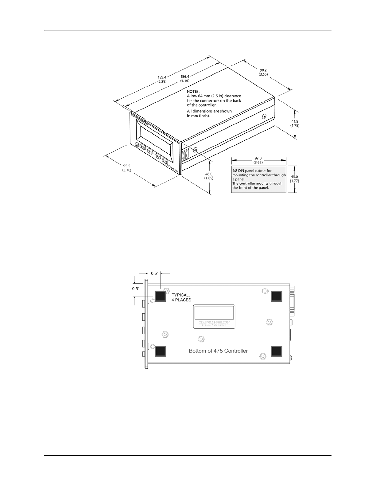
Figure 2-3 Controller Dimensions
Installation
The Controller may be free-standing or panel-mounted. For free standing
(benchtop) use, install the provided self-adhesive rubber feet on the bottom
of the Controller.
To use the Controller in a free-standing (benchtop) configuration:
1. Apply the four provided adhesive rubber mount feet on the bottom of the
Controller.
Figure 2-4 Mount Feet on the Bottom of the Controller
To mount the Controller in a panel, refer to Figure 2-5 and Figure 2-6, and
follow these steps:
• Panel opening dimensions are 92 mm x 45 mm (3.6 inches x 1.77 inch).
• Panel thickness is 3 mm (1/8 inch).
• Provide a minimum of 64 mm (2.5 inch) clearance behind the Controller
to allow for cables.
1. Prepare the panel opening per the dimensions listed on Figure 2-3 and
Series 475 Convectron Gauge Controller Instruction Manual 475101 - Rev. G 19

Chapter 2
the bullet points listed above.
2. Remove the Front Panel (bezel) as shown in Figure 2-5. Hold the
Controller in your hands and use your thumbs to push on the bezel. Push
the bottom of the bezel loose, then the top.
Figure 2-5 Remove the Front Panel (bezel)
3. Insert the Controller through the front of the panel.
2.6 Install the Convectron Gauge
Figure 2-6 Pawl Screw Used to Secure Controller to Panel
4. Use a Phillips head screwdriver to rotate the Pawl Screw to lock the
Controller to the panel. See Figure 2-6.
5. Replace the bezel by aligning it with the keys and push the top and the
bottom of the bezel to snap it into place.
To install Convectron Gauges, refer to Figure 2-7 and follow the instructions
below.
• Orient the Convectron Gauge to prevent condensation of process vapors
on the internal surfaces through line-of-sight access to its interior. If vapor
condensation is likely, orient the port downward to help liquids drain out.
• For proper operation above about 1 Torr, install Convectron Gauges with
the gauge axis horizontal.
20 Series 475 Convectron Gauge Controller Instruction Manual 475101 - Rev. G
Installation
WARNING
Figure 2-7 Convectron Gauge Installation
• Do not locate the Convectron Gauge near the pump, where gauge
pressure might be lower than normal vacuum pressure.
• Do not locate the gauge near a gas inlet or other source of contamination,
where inflow of gas or particulates causes atmospheric pressure to be
higher than system atmosphere.
• Do not locate the gauge where it will be subjected to vibration, which
causes convection cooling, resulting in inaccurate high pressure readings.
• Do not locate the gauge where it will subjected to extreme temperature
fluctuations. For greatest accuracy and repeatability the gauge should be
located in a stable room temperature environment.
Install Vacuum Chamber Fittings
Do not use a compression mount/quick connect fitting for positive pressure
applications. The gauge may be forcefully ejected. The gauge port fits a
standard 1/2-inch compression/quick connect mounting such as an
®
Ultra-Torr
fitting.
Failure to install appropriate pressure relief devices
for high-pressure applications can cause product
damage or personal injury.
For automatic backfilling and other applications in
which malfunction or normal process conditions can
cause high pressures to occur, install appropriate
pressure relief devices.
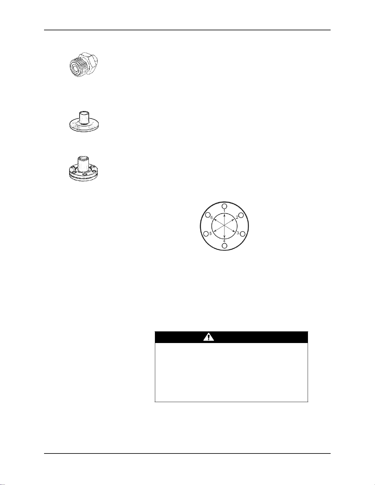
1/8 NPT Pipe Thread The 1/8 NPT pipe thread accommodates a standard 1/8 NPT female fitting.
1. Wrap the threads of the port to the vacuum chamber with thread sealant
tape.
2. Tighten the gauge just enough to achieve a seal. Do NOT over tighten.
Series 475 Convectron Gauge Controller Instruction Manual 475101 - Rev. G 21
Chapter 2
WARNING
VCR Type Fitting 1. Remove the plastic or metal bead protector cap from the fitting.
2. If a gasket is used, place the gasket into the female nut.
3. Assemble the components and tighten them to finger–tight.
4. While holding a back-up wrench stationary, tighten the female nut 1/8
turn past finger-tight on 316 stainless steel or nickel gaskets, or 1/4 turn
past finger-tight on copper or aluminum gaskets.
KF Flange The KF mounting system requires O-rings and centering rings between
mating flanges.
1. Tighten the clamp wing nut to compress the mating flanges together.
2. Seal the O-ring.
ConFlat Flange To minimize the possibility of leaks with ConFlat flanges, use high strength
stainless steel bolts and a new, clean OFHC copper gasket. Avoid scratching
the seal surfaces. To avoid contamination, install metal gaskets.
1. Finger tighten all bolts.
2. Use a wrench to continue tightening 1/8 turn at a time in criss-cross
order (1, 4, 2, 5, 3, 6) until the flange faces make contact. Further tighten
each bolt about 1/16 turn.
Ground the Convectron Gauge
22 Series 475 Convectron Gauge Controller Instruction Manual 475101 - Rev. G
• If the Convectron Gauge has a VCR type fitting or ConFlat flange, it will
be properly grounded via the vacuum chamber connection.
• If the Convectron Gauge has a KF flange or an NPT fitting, use a length of
#12 AWG braided copper wire which connects to the Convectron Gauge
and to the vacuum chamber ground connection. See Figure 3.
Improper grounding could cause product failure or
personal injury.
• Follow ground network requirements for the facility.
• Maintain all exposed conductors at earth ground.
• Make sure the vacuum port to which the gauge is
mounted is properly grounded.
Installation
Analog output connector
I/O (RS-232
or RS-485)
connector
2-channel
process control
(setpoint)
connector
Convectron
Gauge
connector
Power supply
connector
NOTE: The Service Port is
for factory use only.
Chassis
ground
connection
Figure 2-8 Convectron Gauge to Vacuum Chamber Ground Connection
2.7 Connect the Wiring The 475 Controller has connectors for Convectron Gauge cable, RS-232,
RS-485/422, setpoints, analog output cable, and power supply wiring, as
illustrated in Figure 2-9 (
Figure 2-9 Convectron Gauge, Output, and Power Connections
shown with the optional RS-232 and setpoint connectors).
• Connect a #12 AWG ground wire to the chassis ground connection on the
rear of the Controller and to a known Earth ground. Do NOT connect a
ground wire from the Controller directly to the vacuum chamber or system
Series 475 Convectron Gauge Controller Instruction Manual 475101 - Rev. G 23

Chapter 2
WARNING
Locking Tab
ground.
Improper grounding can cause product damage or
personal injury.
Follow ground network requirements for the facility.
• Maintain all exposed conductors at earth ground.
• Connect the power cord to a properly grounded
outlet.
• Make sure the vacuum port to which the gauge is
mounted is properly grounded.
• Connect the gauge envelope to a facility ground or
shield the envelope. If necessary, use a ground lug on
the flange bolt. Ground the gauge envelope by using
a metal hose clamp on the gauge connected by a #12
AWG (minimum size) copper wire to the grounded
vacuum chamber.
• Connect the Convectron Gauge cable between the gauge and the
Controller. See Figure 2-9.
• Connect the power supply by inserting the power cord with the locking
tab up. See Figure 2-10.
NOTE: The 475 Controller is internally limited to 28 Vdc maximum
and 1.4 A. Do not connect the input to high voltage.
Power supply wiring depends on the power supply voltage and the type of
mounting. There are two ways to supply power to the 475 Controller:
1. Use a CE-compliant power supply: 90 to 250 VAC input, 24 Vdc output,
with connection plugs to accommodate the local AC plug type (catalog
number 475008-1 through -4 -- See page 4 of this Instruction Manual).
2. User supplied power to the Controller using a wire adapter and plug to
connect to a 12 to 24 Vdc supply voltage (Granville-Phillips part number
167820). If you use the wire adapter, the wires to be connected to the
user supplied power are marked on the end of the cable:
Outside: Supply ground for 12 to 24 Vdc power supply
Center: +12 to 24 Vdc power < 0.5 A @ 12 V (i.e. < 6 Watts) continuous
(Inrush limited to <1.4 A for <7 msec)
Colored End: Safety chassis ground.
Both options accommodate the same orientation and connection plug. The
locking tab mechanism is on the top side of the connector when you plug it
into the rear panel. See Figure 2-10.
Figure 2-10 Locking Tab for Power Supply Cord
24 Series 475 Convectron Gauge Controller Instruction Manual 475101 - Rev. G
Installation
See Convectron Gauge Analog
Output Signal
on page 53
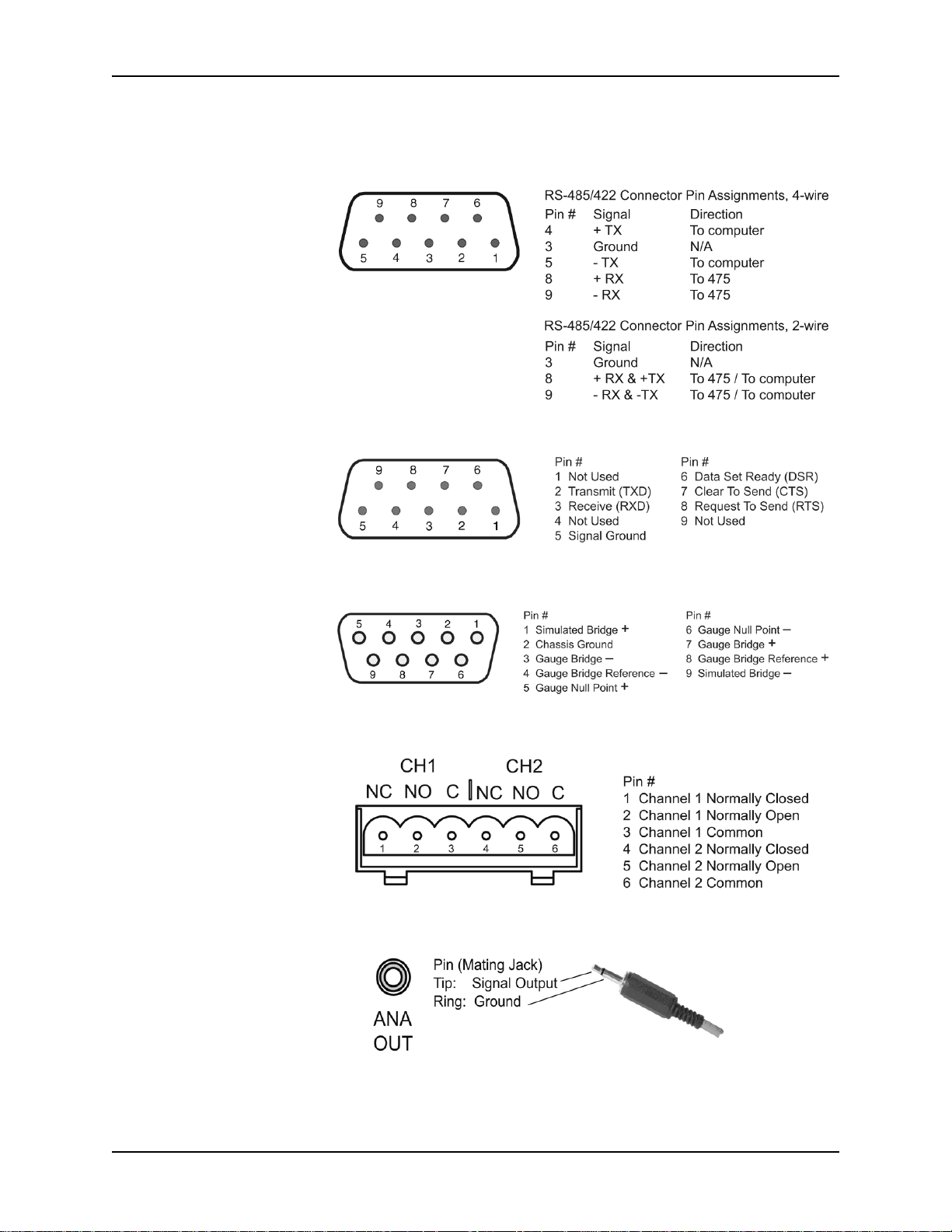
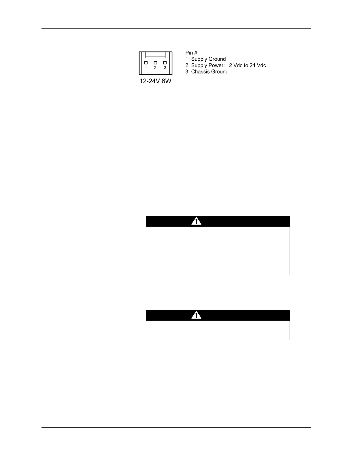
2.8 Connectors The following figures illustrate the connectors on the back of the 475 Controller.
Figure 2-11 I/O (RS-485/RS-422) 9-Pin Connector (pins)
Figure 2-12 I/O (RS-232) 9-Pin Connector (pins)
Figure 2-13 Convectron Gauge 9-Pin Connector (sockets)
Figure 2-14 2-Channel Process Control Connector (pins)
Figure 2-15 Analog Output Connector (socket)
Series 475 Convectron Gauge Controller Instruction Manual 475101 - Rev. G 25
Chapter 2
WARNING
CAUTION
Figure 2-16 3-Pin Power Supply Connector
2.9 Configure the Relays
for the Application
• To configure the setpoint relays for the process control option, see
page 57.
• To configure the setpoint relays using the RS-232 option, see PCE Relays
on page 69.
• To configure the setpoint relays using the RS-485 option, see PCE Relays
on page 87.
If the Controller will measure the pressure of a gas other than N
or air, you
2
must adjust relay setpoints for the process gas. The true pressure of a gas
other than N
or air may be substantially different from the pressure that the
2
output indicates. For example, outputs might indicate a pressure of 10 Torr
(13.3 mbar, 1.33 kPa) for argon, although the true pressure of the argon is
250 Torr (333 mbar, 33.3 kPa). Such a substantial difference between
indicated pressure and true pressure can cause over pressurization resulting
in an explosion. See Using Gases Other than N2 or Air on page 41 and Gas
Species on page 35.
Failure to use accurate pressure conversion data for
or air to other gases can cause an explosion due to
N
2
overpressurization.
If the Controller will measure any gas other than N
2
or air, before putting the Controller into operation,
adjust relays for the process gas that will be used.
2.10 Requirements for
Process Control
Option
If you are using the process control option, you must prepare for process
control operation before turning ON the Controller. See Chapter 4 for
complete process control setup instructions.
Failure to check system setup configuration before
switching to automatic operation can cause errors.
26 Series 475 Convectron Gauge Controller Instruction Manual 475101 - Rev. G
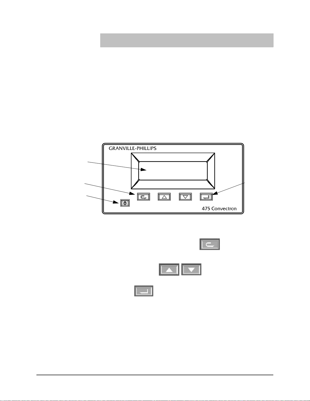
Chapter 3 Operation
Power ON/OFF
Button
Vacuum Fluorescent
Display Screen
Back Button
Enter
Button
3.1 Preparing for
Pressure
Measurement
Figure 3-1 Series 475 Convectron Gauge Controller Front Panel
Before you prepare for process measurement, make sure:
• The Controller was properly set up and installed per the instructions in
Chapter 2.
• The gas in your vacuum system is air or N
you must follow the instructions in Using Gases Other than N2 or Air on
page 41 and Indicated vs. True Pressure for Gases Other Than N
on page 42.
• You are reasonably familiar with the general theory of operation of
thermal conductivity gauges. See Convectron Gauge Theory of Operation
on page 40.
. If you are using other gases
2
or Air
2
3.2 Button Overview • The POWER button is press ON, press OFF. In case of power failure, the
3.3 Initial Power Up 1. Press the Power ON/OFF button (see Figure 3-1). The display screen will
Series 475 Convectron Gauge Controller Instruction Manual 475101 - Rev. G 27
Controller will restart if it was ON when power was interrupted.
• Use the BACK button to exit menus.
• Use the UP and DOWN buttons to make menu selections and change
parameter settings.
• Use the ENTER button to enter menus and to execute parameter changes.
Figure 3-2 page 28 illustrates the button menu flow.
illuminate.
2. Run the self diagnostics tests to allow the 475 Controller to perform a self
diagnostics test. See Diagnose beginning on page 29 to run the tests.

Chapter 3
Figure 3-2 Series 475 Convectron Gauge Controller System Menu Flowchart
3.4 Menu Overview All functions, settings, and options can be accessed and displayed by using
the four buttons on the front panel of the Controller. Some of the displayed
settings are for information only, and others can be changed and saved. Use
either the UP or DOWN button to scroll through the menu selections.
The five main menu selections are Calibrate, Configure, Diagnose, Keypad,
and Product Info. See Figure 3-2. Each of these menu selections and their
relevant sub-selections are explained in the following sections of this
chapter.
When using a PC and the RS-232 option, additional information is provided
in the Process Control Chapter and the RS-232 Chapter.
When using a PC and the RS-485 option, additional information is provided
in the Process Control Chapter and the RS-485 Chapter.
28 Series 475 Convectron Gauge Controller Instruction Manual 475101 - Rev. G

Operation
3.4.1 Product Information
Product information allows the user to read the product revision and
installed options.
1. Press the UP or DOWN button to scroll to “Product Info” and press the
ENTER button.
2. Press the UP or DOWN button to browse the product information.
3. “Code Version” displays the software part number and revision.
4. “Setpoints” displays the number of relays.
5. “Serial Number” is the same as the label on the product.
6. “NIST Calibration” displays “Yes” if the gauge and Controller have been
calibrated on NIST traceable instrumentation, or displays “No” if there’s
no NIST calibration or it has been voided. See NIST Traceable System
Calibration on page 52 for more detailed information.
7. “Serial Interface” displays if the RS-232 or RS-485 serial interface is
installed.
8. Press the BACK button a few times or wait one minute to return to
pressure display.
3.4.2 Keypad The keypad consists of five momentary switches; one is used as a power switch, four are used for user interaction with the display menu.
The keypad can be enabled or disabled.
Disabling the keypad prevents unwanted key presses. When disabled, any
key press (EXCEPT the Power key) causes a "keypad disabled" notification to
be shown for two seconds. The "current pressure screen" is shown by default.
1. Press the UP or DOWN button to scroll to “Keypad” and press the
ENTER button.
2. Press the UP or DOWN button to select “Enable” or “Disable” and press
the ENTER button.
3. Press the BACK button a few times or wait one minute to return to
pressure display.
4. To re-enable the keypad, enter the sequence Up, Down, Back, Enter
within five seconds.
3.4.3 Diagnose During the diagnostics “Test Measurement” function, pressure reporting is
suspended and the Convectron simulator is switched ON. (See Convectron
Gauge Simulator beginning on page 97.) For the "Auto Test”, the Convectron
simulator simulates five different equally-spaced Analog to Digital (A/D)
voltages across the whole range (0.317 to 5.635V). These voltages are
measured and compared by the external A/D and the internal
microcontroller A/D. The Convectron simulator is switched OFF, pressure
reporting resumed, and a pass/fail is reported to the user. See Chapter 7 for
more information on the diagnostics.
The same process is used for the "Manual Test", except the user can enter
either pressure or bridge voltage and pass/fail criteria is not determined by
the microcontroller.
During the Analog Output diagnostic function, pressure reporting is
suspended to the analog output, and the analog output is tested at discrete
points between 0 V and 10.5 V.
1. Press the UP or DOWN button to scroll to “Diagnose” and press the
Series 475 Convectron Gauge Controller Instruction Manual 475101 - Rev. G 29

Chapter 3
ENTER button.
2. Press the UP or DOWN button to select “Auto Test”, “Meas. Circuit”, or
“Analog Output” and press the ENTER button.
• Auto Test All
Performs the “Auto Test” described above.
1. Press the ENTER button to allow the 475 Controller to automatically
perform a self diagnostics test.
• Test Measurement Circuit
The “Auto Test” mode automatically tests the Measurement Circuits. In the
“Manual Test” mode, you can enter a voltage signal for the Bridge Voltage,
or a pressure rating to simulate system pressure.
1. Press the UP or DOWN button to select “Auto Test” or “Manual Test”
and press the ENTER button.
2. In the “Auto Test” mode, press the ENTER button to allow the 475
Controller to perform the diagnostics check.
3. In the “Manual Test” mode, use the UP or DOWN button to select either
Bridge Voltage or “Pressure” and press the Enter button.
4. Press the UP or Down button to enter the desired voltage in the “Bridge
Voltage” mode, or the desired pressure in the “Pressure” mode.
• Test Analog Output
The “Auto Test” mode automatically tests the Analog Output Circuits. In the
“Manual Test” mode, you can enter a voltage to apply to the Analog Output
to simulate system pressure or for system setup.
1. Press the UP or DOWN button to select “Auto Test” or “Manual Test”
and press the ENTER button.
2. In the “Auto Test” mode, press the ENTER button to allow the 475
Controller to perform the diagnostics check.
3. In the “Manual Test” mode, press the UP or Down button to enter the
desired voltage to be output.
4. Press ENTER to perform the diagnostics check.
3.4.4 Calibrate When the Calibrate function is selected, the 475 Controller reads the current pressure in the vacuum chamber and determines whether you can calibrate at atmosphere or vacuum based on the current pressure.
See Calibration and NIST Traceable System Calibration on page 52 for more
detailed information.
1. Press the UP or DOWN button to scroll to “Calibrate” and press the
ENTER button.
Either “Calibrate Vacuum” or “Calibrate Atmosphere” will be shown
depending on the current reported pressure.
NOTE: “Invalid Pressure for Cal” will be displayed if the pressure is
out of range to perform the calibration.
• Calibrate Atmosphere
1. Press the UP or DOWN button to select the desired calibration setting
and press the ENTER button.
2. Press the BACK button a few times or wait one minute to return to
30 Series 475 Convectron Gauge Controller Instruction Manual 475101 - Rev. G
 Loading...