


HPAW65
Grant Aerona Air Source Heat Pump
Air to Water Heat Pump Range
Installation & User Instructions
Part No. DOC.87 Rev.00 January 2010
Tested to BS EN 14511

i
STOP
STOP!
Has a heat loss calculation been carried out? kW
Is this system designed for Mono or Bivalent
If Mono, total heating capacity? kW
If Bivalent, what is the load capacity of Heat Pump? kW
If Bivalent, what is/are additional heat source(s)?
i) kW
ii) kW
iii) kW
Type of system design?
i) S-plan
ii) Y-plan
iii) Other
Will a buffer be used? Yes/No
If yes, what is the capacity of Buffer? litres
Has cavity wall insulation been installed? Yes/No
Has loft insulation of 270mm been installed? Yes/No
Have all system pipes been lagged correctly? Yes/No
Are the existing controls being upgraded? Yes/No
Before continuing with the installation of your new Aerona Heat pump, please spend
a few minutes confirming the suitability of the Heat Pump to your system. Failure to
do so may result in poor performance and wasted time.
If any of the above questions cannot be answered accurately, please do NOT
proceed with the installation. While any errors made now may be able to be
compensated for after the installation is completed, you will incur unnecessary
delays and additional costs.

Legislation
ii
All work that is required regarding the refrigerant circuit must be carried out by an
F-gas registered (or equivalent) refrigeration Engineer. On no account should
maintenance or repair be carried out on the refrigerant circuit by unqualified
personnel.
LEGISLATION
The installation of the Grant Aerona Heat Pump requires a power supply cable from
the customer’s consumer unit to an external isolation switch and from this switch to
the heat pump. It will require a final connection to an individual MCB or RHBO within
the existing consumer unit or from a newly installed consumer unit.
This work MUST be carried out by a qualified electrician or by a Part-P competent
installer who has passed an examination proving their competency in these works.
Failure to follow this legislation will invalidate all warranties.
Please seek advice from a competent person before commencing any electrical
work.
Legislation
Information regarding the refrigerant used in this Heat Pump. R407c
R407C is a mixture of three refrigerants, each of which boil at different temperatures. R407C has a range or glide of approximately
5ºC. The lubricating oils used in this heat pump are known as Polyolester or POE oils. They are considered to be superior oils, less
liable to breakdown however they are more hygroscopic – they must therefore be kept from contact with air as far as is practical.
Information regarding the charging / recharging of the unit.
Always add R407C as a liquid to ensure that the correct mix is added.
Charge the heat pump with the correct weight of refrigerant. See data plate for this information.
Never ‘top-up’ refrigerant. Always recover the remaining refrigerant first for recycling.
Information regarding a refrigerant leak or if the circuit is opened accidentally.
Recover the remaining refrigerant as quickly as possible for recycling.
Avoid entry of air into the heat pump as much as possible.
Replace or install a drier if necessary.

iii
Contents
Contents
Stop! i
Legislation ii
Contents iii
1 Introduction 1
1.1 General Information 1
1.2 Warranty 1
1.3 Important Advice 1
1.4 Immersion Heater 1
2 Specifications and Controls 2
2.1 Specifications 2
2.2 Dimensions 2
2.3 Main Components 3
2.4 Heat Pump Curves 4
2.5 Pump Curves 5
2.6 Operating Sequences 5
2.7 Controls 6
3 Siting the Heat Pump 7
3.1 Position 7
3.2 Orientation 8
4 Hydraulic Diagrams 9
4.1 S-Plan Type - Monovalent 9
4.2 Extended S-Plan Type - Monovalent 9
4.3 S-Plan Type - Bivalent 10
4.4 Extended S-Plan Type - Bivalent 11
4.5 Buffer Tanks 12
4.6 S-Plan with Buffer - Monovalent 12
4.7 Extended S-Plan with Buffer - Monovalent 13
5 System Design Criteria 14
6 Calculating Radiator Sizes 15
7 Sealed Systems 16
8 Electrical 17
8.1 General 17
8.2 Basic Circuits – Making the Connection 17
8.3 Controller 19
8.4 Mains Supply Cable 19
8.5 Heat Pump Wiring Diagram 20
8.6 System Control Wiring Diagrams 22
8.7 Wiring Diagrams 23
8.8 Bivalent Systems 25
8.9 Extending the Electrics 25
9 Domestic Hot Water 26
9.1 Temperature Control 26
9.2 Heat Pump Cylinders 26
9.3 Temperature Boost 26
10 Filling the System 28
10.1 Filling and Venting - Sealed Systems 28
10.2 Flushing and Corrosion Protection 28
10.3 Antifreeze 28
11 Commissioning 29
11.1 Switching on First Time 29
11.2 Setting the ATC Controller 30
11.3 Setting the BTC Controller 32
11.4 Record of ATC and BTC Settings 34
12 Servicing & Maintenance 35
12.1 General 35
12.2 Air Inlet and Outlet 35
12.3 Condensate Disposal 35
12.4 Heating System Connections 35
12.5 Heat Pump Controls 35
12.6 Refrigerant 35
13 Fault Finding 36
14 Spare Parts 40
15 Accessories 41
15.1 Sealed System Kits 41
15.2 Immersion Heater Kits 41
16 Glossary Of Terms 42
17 Warranty 43

Introduction &
General Information
1
1.1 General Information
The Grant Aerona Heat Pump is a low
water content – low temperature heat
source, designed to be highly efficient
when installed and used in line with
these installation and user instructions.
It is important that these installation
instructions are understood and
followed to ensure reliable operation in
all weather conditions. Failure to do so
will result in erratic temperature swings,
poor efficiency and an unhappy
customer.
It is not within the scope of this manual
to design the heating system or provide
any advice regarding the layout of the
system or any of the controls required
for any individual heating system.
These instructions do not replace the
installation or users manuals for any
additional components used in the
design of your system e.g. cylinders,
motorised valves, programmers, solar
thermal devices, buffers, etc.
Grant Engineering UK Ltd offer a design
service for an additional fee – please
contact info@grantuk.com for more
information or visit our website at
www.grantuk.com Note: this service
is subject to the terms and conditions in
force at the time of the design.
These instructions must be left with the
householder for their reference.
1.2 Warranty
This appliance is guaranteed for two
years, covering parts and labour. When
making a claim against this warranty,
the following information must be
provided at the initial point of contact.
• Appliance model number
• Appliance Serial number
• Date of Installation
• Date of Commissioning (if different)
• Evidence of Heat Loss calculation
• Description of fault together with any
relevant fault codes
Please ensure that the caller is
on site to assist us in providing
a fast response.
The warranty will begin only when a
completed registration card is returned
to Grant, or when the registration is
completed online at www.grantuk.com.
Failure to complete the registration at
the time of installation will result in the
warranty being suspended. This does
not affect the consumer’s statutory
rights.
If a Grant Engineer is required to visit
the site and no fault is found with the
heat pump, a charge will be made for
this visit. The original caller will be
responsible for this charge.
Refer to Section 17 for full details of the
Grant Heat Pump warranty.
1.3 Important Advice
1. It is essential that the full layout of
the system is understood before the
installation of any component is
undertaken. If you are in any doubt,
please stop and seek advice from a
qualified heating engineer or from
Grant Engineering UK Ltd. Please
note that Grant Engineering will not
be able to offer specific advice
about your system unless we
designed it. In this case, we will
always refer you to seek the advice
of a qualified system designer.
2. The Heat Pump must be installed
and commissioned in accordance
with these installation instructions.
Deviations of any kind will invalidate
the warranty and may cause an
unsafe situation to occur. Please
seek advice from Grant Engineering
UK Ltd if any of these installation
instructions cannot be followed for
whatever reason.
3. The heat pump contains high
pressures and high temperatures
during normal working conditions.
Care must be taken when
accessing the internal workings of
the heat pump.
4. The heat pump contains an
electrically driven fan which rotates
at high speed. Disconnect the heat
pump from the electrical supply
before removing the top cover.
1.4 Immersion Heater
All Grant Aerona Heat pumps are
supplied with a factory fitted 3kW
immersion element. This is designed to
operate at low ambient air temperatures
to increase the output of the unit to
meet the design heat load. Refer to
Section 11 of these instructions for
details of the automatic operation of the
immersion element.
If required, all Grant Aerona Heat
pumps are available with a 6kW backup immersion element (in place of the
standard 3kW unit).
This is a factory fitted option ONLY and
must be specified when ordering the
heat pump.
For the starting and running current,
along with the required MCB rating/type
for units with either the 3kW or 6kW
immersion elements refer to Section 8
(page 21) of these instructions.
1 Introduction & General Information
IMPORTANT
Grant Aerona heat pumps should be stored and
transported in an upright position. If not, the heat
pump MUST be positioned in an upright position for
at least 4 hours before being operated.
2
Specifications and
Controls
2 Specifications and Controls
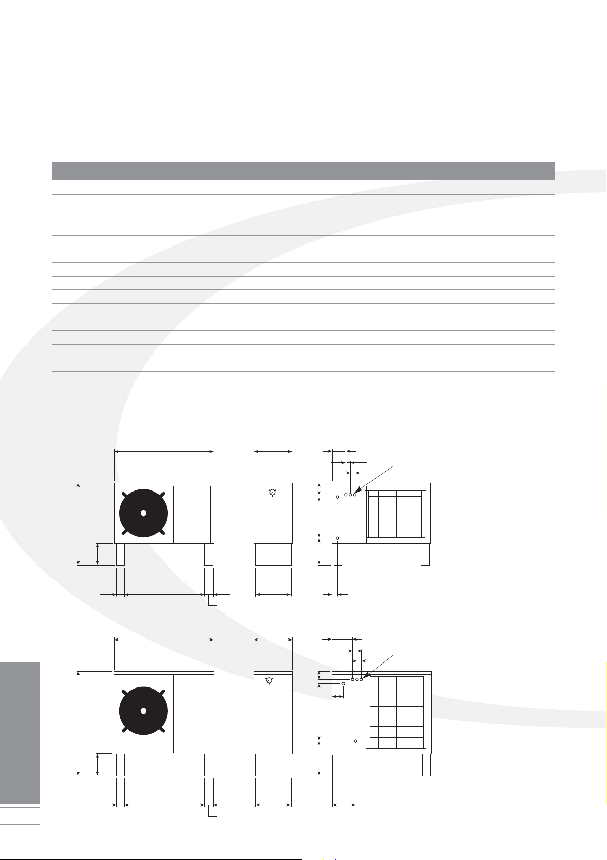
2.1 Specifications
2.2 Dimensions
Model HPAW65 HPAW85 HPAW110 HPAW130 HPAW155
Heating Capacity kW 6.78 8.73 11.32 12.58 15.5
Input Power kW 1.62 2.20 2.61 2.59 2.77
Running Current A 7.36 10.0 11.7 11.8 12.6
Power supply V 230 230 230 230 230
Phase Single Single Single Single Single
Frequency Hz5050505050
Mechanical Protection IP X4 IP X4 IP X4 IP X4 IP X4
Refrigerant R407c R407c R407c R407c R407c
Mass of R407c g 1300 1750 1900 2200 2300
Built In Immersion kW 3 3333
Circulating Pump m head 6 6 6 6 15
Flow Rate litres/sec 0.311 0.422 0.54 0.61 0.724
Sound Level at 1m dB(A) 52 52 52 52 58
Water Connections BSPF
3
/4"
3
/4"1" 1" 1"
COP @ Air 7˚C/Water 35˚C 4.1 3.9 4.3 4.8 5.8
Weight (empty) kg 94 115 138 152 172
Weight (full) kg 111 134 156 170 191
1120 430 165
Electrical inlet
glands
50
50
900
Front View Rear View
90
90
920
250
125485307
400 70
1120 430
200
110
Electrical inlet
glands
Flow
Return
Flow
Return
50
50
900
Front View Rear View
90
90
1165
250
85690395
400
265
Figure 2-1: HPAW65 model
Figure 2-2: HPAW85, HPAW110 & HPAW130 models
Specifications and
Controls
3
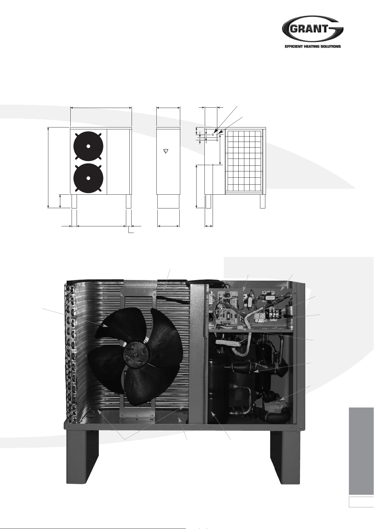
2.2 Dimensions
1120 430
235
Electrical inlet
glands
Flow
Return
900
Front View
Fan
Rear View
90
90
1470
250
130
50
50
555
788
400
145
2.3 Main Components
Figure 2-3: HPAW155 model
Figure 2-4: Main internal components
Evaporator coil Control panel
(cover removed)
Position of Immersion
heater with Auto air vent
Condensate
drain holes
in base
Trace heater
element in
base of unit
(not shown)
Notes: Condensate deflector omitted
from below heat pump casing controller
BTC controller omitted from control
panel for clarity
Condensor
Circulating
pump
Compressor
ATC controller
connection
plug
Mains supply
terminals
Heating
controls
terminals

4
Specifications and
Controls
2 Specifications and Controls
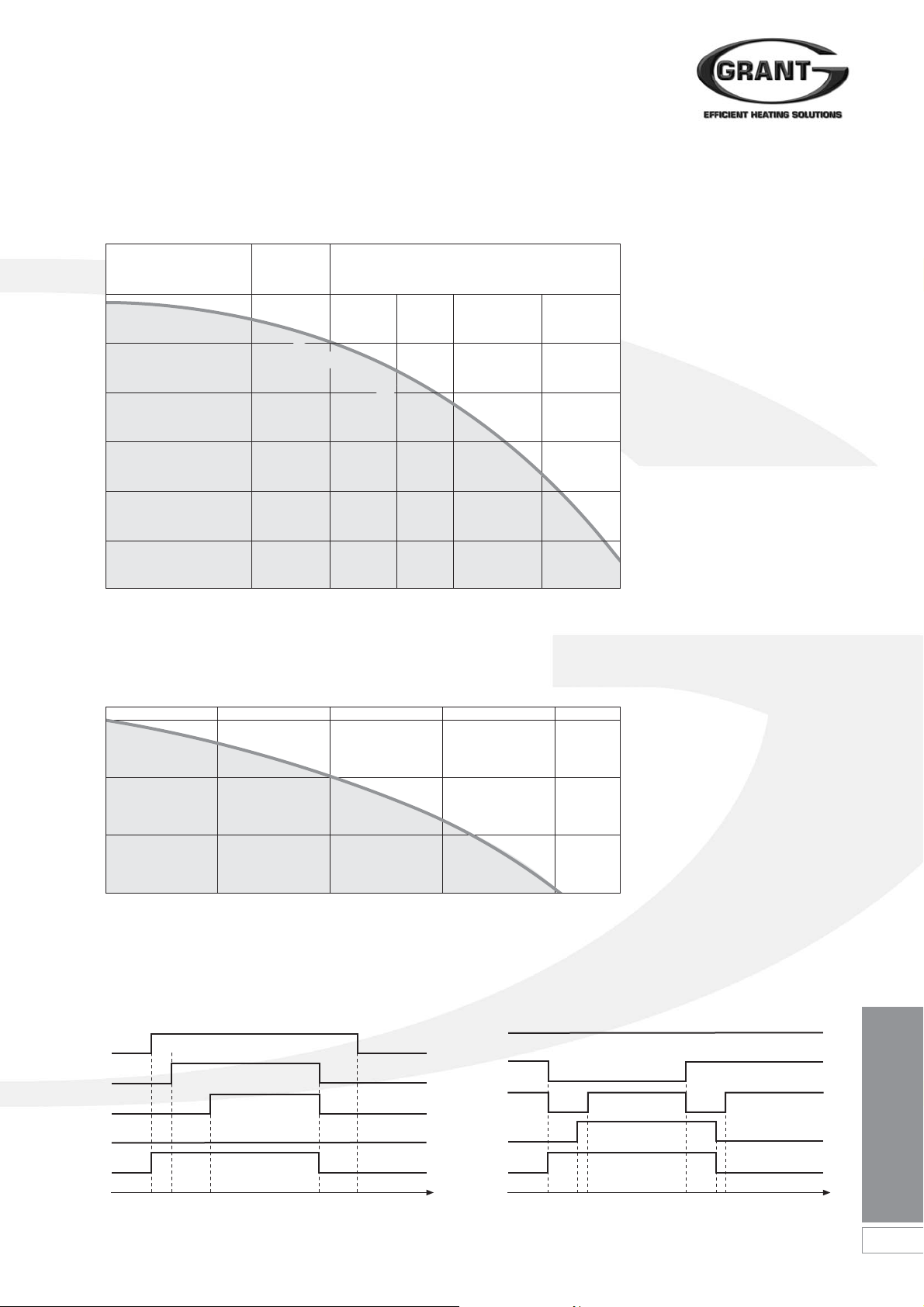
2.4 Heat Pump Curves
Water Flow
Temperature
35˚C
50˚C
Air Temperature in ˚C
Heat Pump Output in kW
-10 0 10 20 30 40
16
14
12
10
8
6
4
2
0
COP
4.1
COP
4.8
COP
3.9
COP
4.3
COP
5.8
Water Flow
Temperature
35˚C
50˚C
Air Temperature in ˚C
Heat Pump Output in kW
-10 0 10 20 30 40
16
14
12
10
8
6
4
2
0
16
14
12
10
8
6
4
2
0
Water Flow
Temperature
35˚C
50˚C
Air Temperature in ˚C
Heat Pump Output in kW
-10 0 10 20 30 40
16
14
12
10
8
6
4
2
0
Water Flow
Temperature
35˚C
50˚C
Air Temperature in ˚C
Heat Pump Output in kW
-10 0 10 20 30 40
Water Flow
Temperature
35˚C
50˚C
Air Temperature in ˚C
Heat Pump Output in kW
-10 0 10 20 30 40
16
14
12
10
8
6
4
2
0
All Grant Aerona heat pumps have
been independently third party
tested to BS EN 14511. The COP
data given above is based on 7˚C
ambient air and 35˚C water
temperature. This information should
be used as guidance only and not to
estimate the COP at other
temperatures.
!
NOTE
Figure 2-5: Grant HPAW65 Figure 2-8: Grant HPAW130
Figure 2-6: Grant HPAW85
Figure 2-7: Grant HPAW110
Figure 2-9: Grant HPAW155
Specifications and
Controls
5
2.5 Pump Curves
Pump Head (metres)Pump Head (metres)
6
5
4
3
2
1
0
Wilo-Classic Star
0 0.5 1 1.5 2 3)
Flow (m
3
/h)
Flow (m
3
/h)
S
t
a
r
-
R
S
1
5
/
6
.
2
5
/
6
2.6 Heat Pump Operating Sequences
Pump OFF
ON
ON
ON
ON
OFF
OFF
OFF
OFF
0
(on)
0
(off)
25 30 25 30
Fan
Comp
Demand
Fan
Pump
OFF OFF
OFF
OFF
ON
ON ON
ON ON
OFF
OFF
ON
ON
ON
Comp
4-way
valve
Defrost
signal
0
(on)
10 60 off BTC
Pump delay
time
Time secs Time secs
15.5kW Pump Curve
15
10
5
0
0 1.2 2.4 3.6 4.8
PUN-200E
Figure 2-10: Pump curve for HPAW65, HPAW85, HPAW110 & HPAW130
Figure 2-12: Normal operating sequence Figure 2-13: Defrost cycle
Figure 2-11: Pump curve for HPAW155
6
Specifications and
Controls
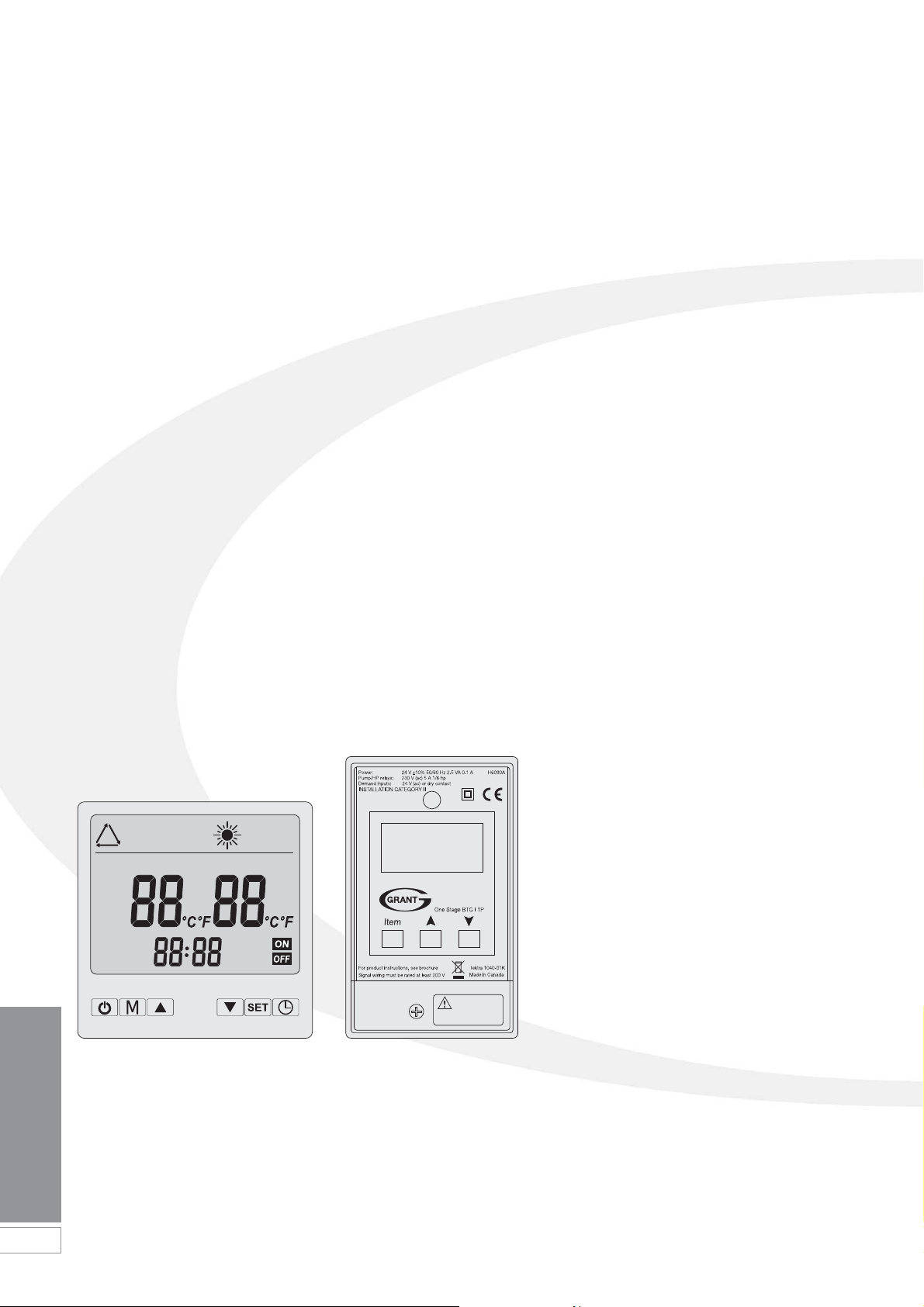
All Grant Aerona Heat Pumps are
supplied with 2 controllers. 1 x heat
pump controller (ATC) and 1 x
temperature controller (BTC).
The ATC is positioned inside the
house/building and is normally used in
an automatic condition. There are a few
parameters that can be adjusted
including time and maximum water
temperature. The details of these
settings can be found in Section 11 of
this manual.
The BTC is a split temperature
controller located inside the heat pump.
For many installations, the DHW
temperature and the CH temperature
will be different. The BTC allows for 2
different design temperatures to be
entered, maximising the efficiency of the
Grant Aerona heat pump. The details of
these settings can be found in Section
11 of this manual.
All other controls (programmers,
motorised valves, thermostats, etc) are
not supplied but their use is covered in
Sections 4 and 8 of this installation
manual.
2.7 Controls
2 Specifications and Controls
Figure 2-11: ATC Controller Figure 2-12: BTC Controller
Siting the Heat Pump
7
3 Siting the Heat Pump
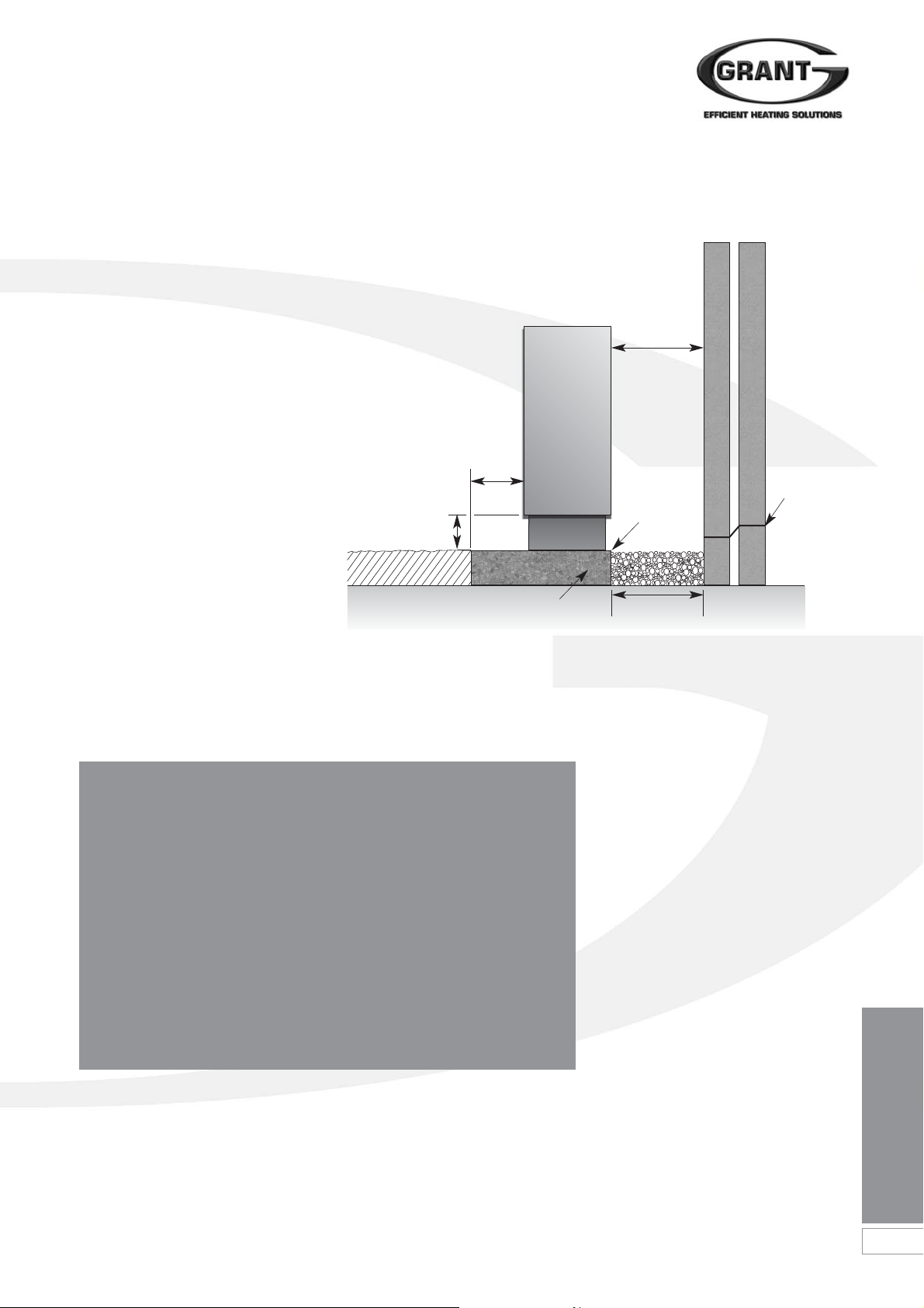
1. Base
The heat pump should be installed
on a flat trowelled finished concrete
base 150mm thick. This base
should extend at least 100mm
beyond the unit on three sides. The
edge of the concrete base on the
side closest to the building should
be flush with that face of the heat
pump. Refer to Figure 3-1.
To avoid bridging the DPC, leave a
gap of at least 300mm between the
concrete base and the wall of the
house.
The Underside of the heat pump is
fitted with a condensate deflector
that directs the condensate to the
rear of the unit. To allow this
condensate to safely drain away,
there should be a shallow trench at
least 150mm wide, filled with stone
chippings, along the rear edge of
the concrete base. This trench can
extend across the gap between the
concrete base and the house
(minimum distance 300mm) but the
chippings must be below the
building DPC level.
3.1 Position
300mm
Figure 3-1: Installation details
100mm
min
200mm min above
ground level
150mm
minimum
Trench with chippings
Edge of base
flush with rear of
heat pump
Concrete base
DPC
IMPORTANT
It is essential that the condensate is able to drain
away and not allowed to run onto any adjacent
paths or driveways where, in winter, this will result
in icing and a potential hazard for anyone walking
near the heat pump.
The top of the concrete base must be either level with,
or above, the surrounding ground level. Always ensure
at least 200mm vertical clearance between the
surrounding ground level and the underside of the
heat pump to allow for adequate air movement. Refer
to Figure 3-1 for details.
2. Clearances
The Heat pump should have a
minimum of 300mm from the rear
of the unit to any wall and not have
any obstruction within 1000mm
from the front or either side of the
unit. Do not rest objects on top or
against any part of the heat pump
under any circumstances. Do not
insert objects into the fan guard.
3. Noise Level
All heat pumps make a noise.
Discuss the potential nuisance
factor with the end-user when
considering the final position of the
heat pump. Take opening windows
and doors into account. It is not
essential for the heat pump to be
positioned next to a wall of the
house. Behind an out-building may
be more suitable so discuss the
options with the end-user.
4. Insulation
Remember, all pipe work,
irrespective of length, must be well
insulated to prevent heat loss. The
use of barrier plastic pipe together
with double thick insulation is
strongly recommended, particularly
when considering longer pipe runs.
8
Siting the Heat Pump
3 Siting the Heat Pump
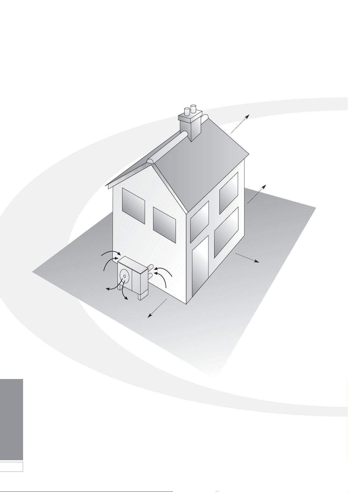
The North face of a building will usually
have colder ambient air than any other
side. To ensure maximum efficiency
from the Grant Aerona heat pump,
position the unit on a warmer side. In
order of preference, site the unit on a
South face followed by either South
East or South West, then by East or
West. Only install on a North face if
there is no other alternative.
3.2 Orientation
North
Cooler ambient air
East
South
Figure 3-2: Location of air source heat pump

Hydraulic Diagrams
9
4 Hydraulic Diagrams
4.1 S-Plan Type - Monovalent
4.2 Extended S-Plan Type - Monovalent
Heat Pump
ATC
Heat Pump
ATC
Flow
Flexible
pipe
Auto
Bypass
Isolating
valve
Isolating
valve
Return
CH Flow
DHW Flow
CH Return
DHW Return
CH Return
DHW Return
Cylinder
Stat
Room
Stat
Internal wiring
centre
Heating Load
Heating Load
Heating Load
Programmer
Grant Aerona
Heat Pump
Primary
Pump
Condenser
CH Flow
DHW Flow
Cylinder
Stat
Room
Stat
Internal wiring
centre
Programmer
Figure 4-1: Monovalent system - with S-Plan type controls
Figure 4-2: Monovalent system - with extended S-Plan type controls
Outside
wall
Outside
wall
Flow
Flexible
pipe
Auto
Bypass
Isolating
valve
Isolating
valve
Return
Grant Aerona
Heat Pump
Primary
Pump
Condenser
The following are examples of suitable systems
IMPORTANT
The following system diagrams
are only concept drawings and
not detailed engineering
drawings. They are not intended
to describe complete systems,
nor any particular system.
It is the responsibility of the
system designer, not Grant
Engineering UK Ltd., to
determine the necessary
components for and
configuration of the particular
system being designed including
any additional equipment and
safety devices to ensure
compliance with building and
safety code requirements.
10
Hydraulic Diagrams
4 Hydraulic Diagrams
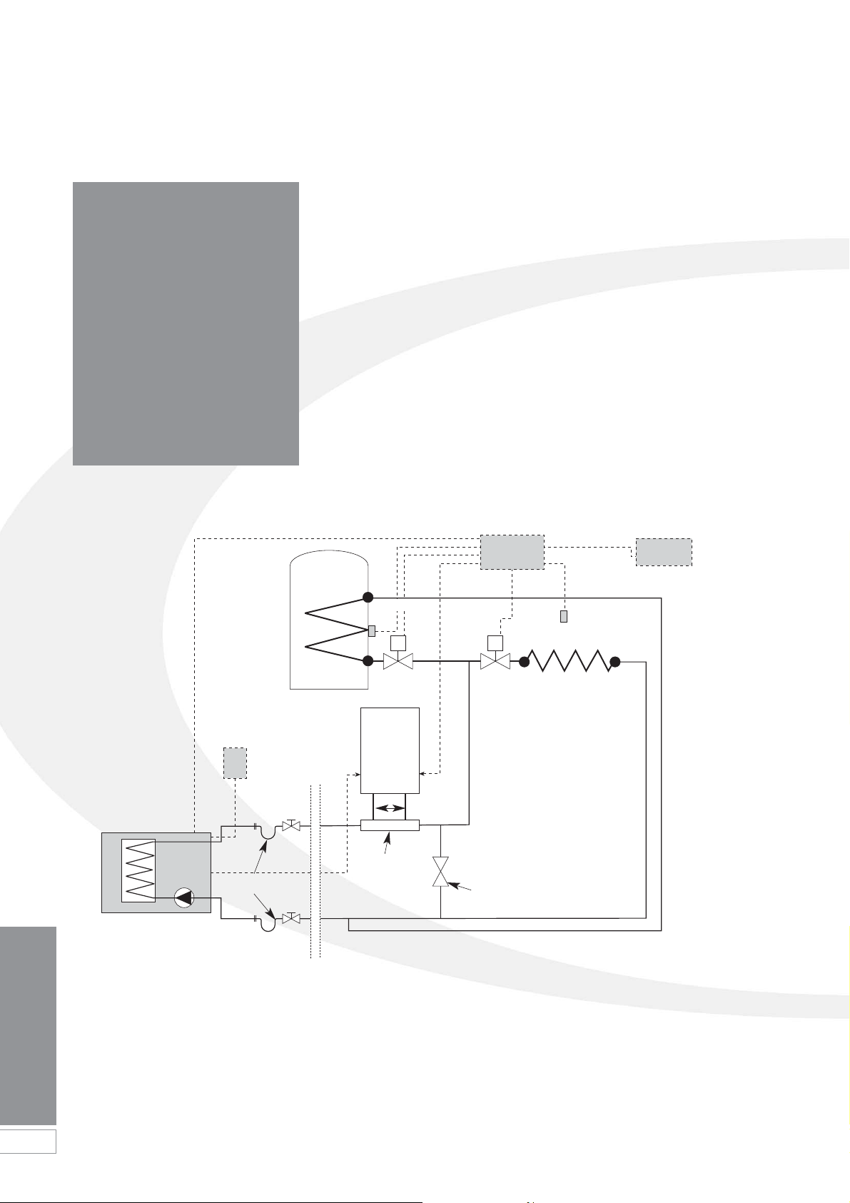
4.3 S-Plan Type - Bivalent
CH Flow
DHW Flow
Heating Load
DHW Return
CH Return
Room
Stat
Internal wiring
centre
Programmer
Boiler
200mm
minimum
R F
Cylinder
Stat
The following are examples of suitable systems
Figure 4-4: Bivalent system - with boiler manifold and S-Plan type controls
Outside
wall
Auto Bypass
Boiler
manifold
Flow
Flexible
pipe
Isolating
valve
Isolating
valve
Return
Grant Aerona
Heat Pump
Primary
Pump
Condenser
Heat Pump
ATC
IMPORTANT
The following system diagrams are
only concept drawings and not
detailed engineering drawings.
They are not intended to describe
complete systems, nor any
particular system.
It is the responsibility of the system
designer, not Grant Engineering UK
Ltd., to determine the necessary
components for and configuration of
the particular system being
designed including any additional
equipment and safety devices to
ensure compliance with building
and safety code requirements.
Hydraulic Diagrams
11
200mm
minimum
CH Flow
DHW Flow
Outside
wall
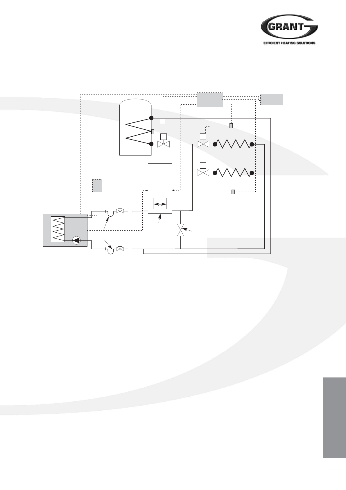
4.4 Extended S-Plan Type - Bivalent
Heating Load
Heating Load
DHW Return
CH Return
Room
Stat
Room
Stat
Internal wiring
centre
Programmer
Boiler
R F
Cylinder
Stat
Figure 4-6: Bivalent system - with boiler manifold and extended S-Plan type controls
Auto Bypass
Flow
Flexible
pipe
Isolating
valve
Isolating
valve
Return
Grant Aerona
Heat Pump
Primary
Pump
Condenser
Heat Pump
ATC
Boiler
manifold
 Loading...