

Page 1
Telescopic rod projector lift installation manual
Model: GPCD58 Series
Grandciew Crystal Screen Guangzhou Co.,Ltd.
Guangzhou Jude Intelligent Audiovisua l Equipment Co., Ltd.
No.43 S, Guomao Ave. H ualong, Panyu, Guangzhou, Guangdong, P.R.C
http://www.grandviewscreen.com
After-sales service T el:0 20-84899499
Tha nk yo u for pu rch asin g thi s prod uct . Plea se re ad the m anu al car efu lly be for e use.
Ple ase r ead th e col lect ion a fter r ead ing fo r fut ure re fer ence .
Page 2
FAQ
The d esi gn of th is pr oduc t can b e used w ith out fa ilu re for m any y ears , man y prob lem s are ca use d by sim ple t hing s.
If so met hing g oes w rong , che ck out o ur si mple f ix li st.I f the p robl em co ntin ues , plea se co ntac t the a utho riz ed dea ler
or ca ll th e afte r-s ales s erv ice nu mbe r: 020 -84 8994 99- 509
The cause of the trouble
The elevator is fully
installed but not
working properly
Remote c ontr ol
doesn' t resp ond
Positioning confusion
Layer board
Close the door shake
Open the door shake
Positive and negative electrode of generator battery is
installed backward or the battery power is insufficient
The p owe r cord i s not p rope rly c onne cte d
Bad rece ptio n/T he sig nal b lock Restar t the li ft po wer su ppl y
Line problem
Motor heating protection
The adjustment screw becomes loose during transportation
The adjustment screw becomes loose during transportation
Ch eck w heth er th e bat tery is ins tall ed bac kwar d acc ordi ng to t he
in stru ctio n. If t he fau lt is n ot re move d, pl ease repl ace t he ba tter y
Connec t the po wer c ord ac cor ding t o the i nstr uct ion
Contact factory or distributor
Wait for motor cooling
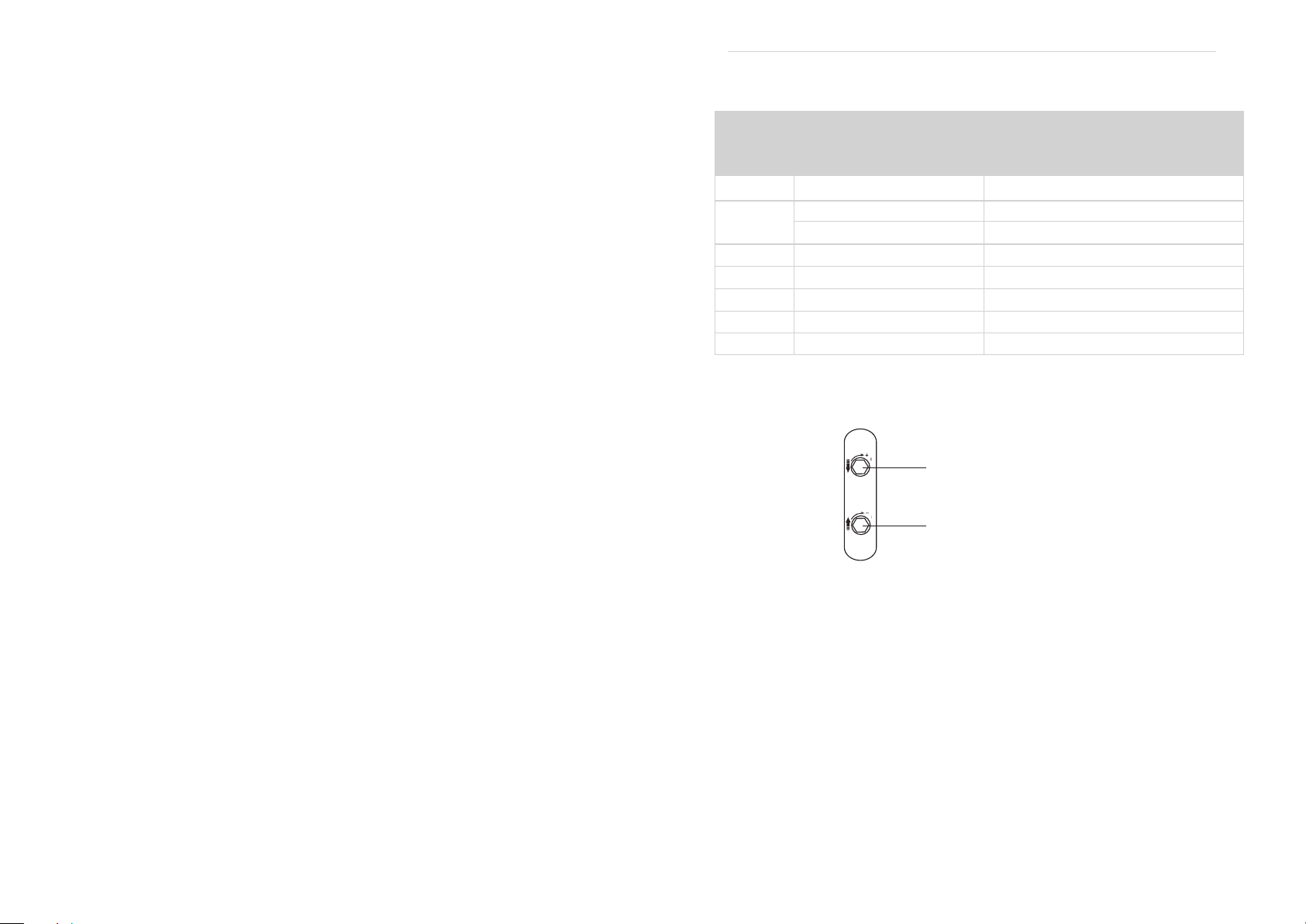
Refer to p ictu re 9 fo r a slig ht cl ockw ise h alf tu rn
Refer to the yellow mark in picture 9 and turn it clockwise slightly for half a turn
Left and right corresponding door panel adjustment indication diagram:
Gre en la bel ad jus tmen t hol e-th e doo r shut ter ed
as it clos ed(clo ckw ise)
Yell ow lab el ad just men t hole -th e door s hut tere d
as it clos ed(clo ckw ise)
Figure 9
The solutionTrouble
Page 3
Caution
1.Please ensure the installation ceiling be secure enough to avoid fa lls , The l oad ing c apa cit y
must be 4 times of the projector lift and the projector.
2.Please tighten all the screws and check whether it become loose regularly, to en sur e saf ety u se.
3.Please do some regular maintenance.
A.When dirty mark there, please gave the lift a polish with a soft duster.
B.When dust there, please remove with soft brush.
4.Kindly suggest a specialist to manage this device, then ensure security and smooth use.
5.Please ensure the lift up and down via Remote control, no pulling with hands.
6.Always retract the lift to the ceiling after use.
7.Ensure the power outlet is connecting with grounding wire.
8.There is no need to add the lubricant to the motor. Do not regulate the motor by yourself, the motor
is already in the right position before delivery, Ple ase c all a s pec ial ist t o hel p you o n thi s whe n it is
in needed.
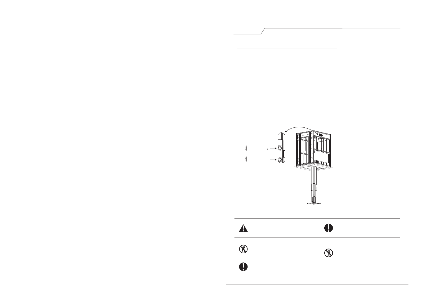
Lower limitation
Upper limitation
Please do read the caution, incorrect
operation will cause accident and product
damage.
When the lift is fully lowered, the bottom
of the lift should be no less than 1.8 meters
away from the ground to avoid being touched
by children。
Please always retract the lift to the ceiling
after use, prevent the dust entering.
Please i nsta ll th e lift i n the p lace w ith
str ong er loa din g capa cit y, oth erw ise
accide nt may h app en and f all ing ri sk
the re.
Do not take apart the lift by yourself,
Please call a specialist to help you on
this when Fix and regulating job in needed
1
Page 4
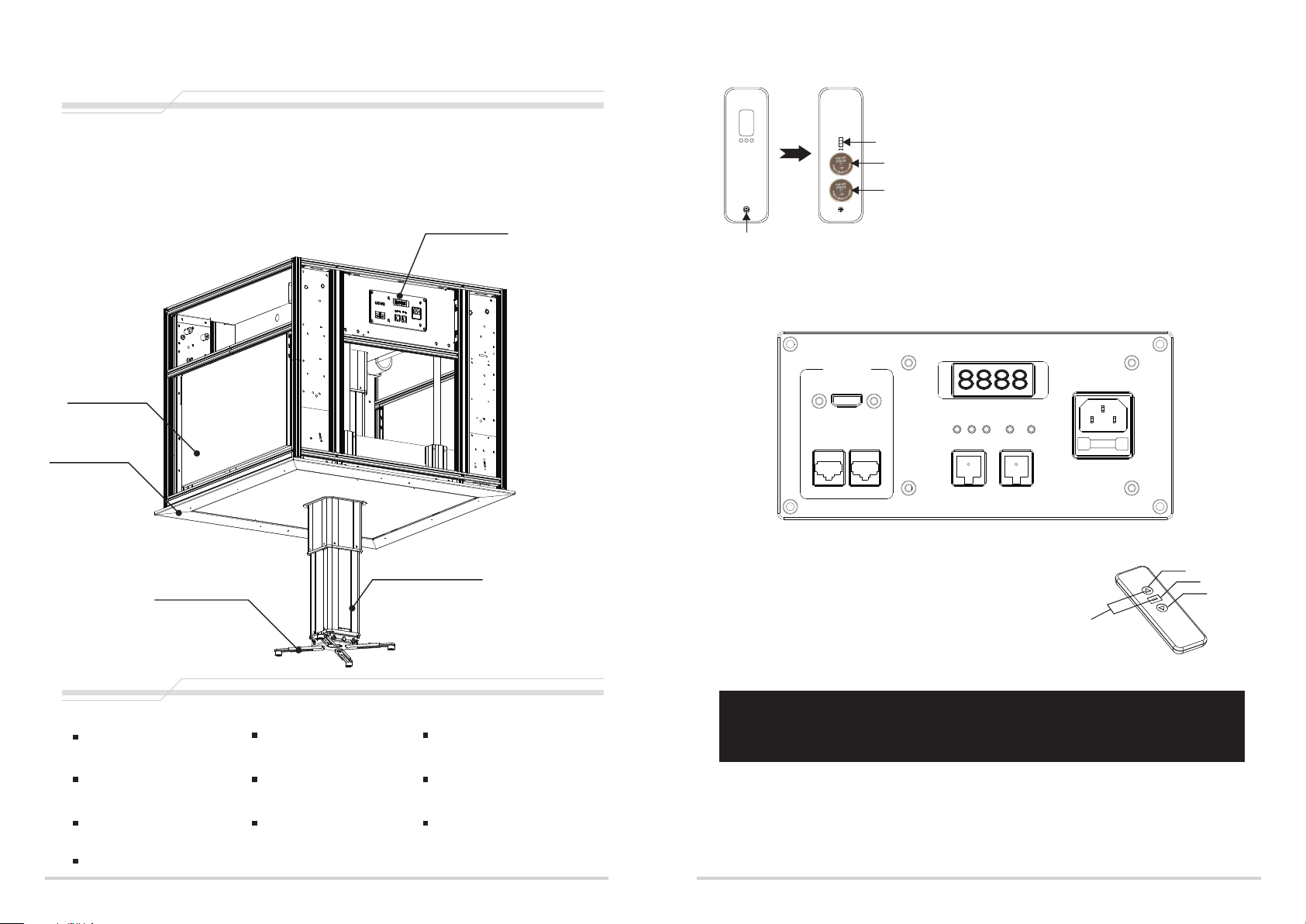
Components
GPAD64 Seri es Proj ect or Lift
1.Cont rol p ane l
2.Elec tri c cei ling door
3.Ceil ing b eze l
4.Telesc opi c Arm s
5.Proj ect or mo unting Bra cke t
Contr ol pa nel
Traction wire electronic
positioning setting button
Batter y
Batter y
and cover
Remote control backRemove the screw
Remote co ntrol lea rning mod e
Remot e control No tes
1.Wo rki ng te mpe rat ure : -2 0℃ to + 70℃
2. Battery: 2 pcs of RC2032 button battery
3.Requires replacement battery when given
signal weak
Battery installation:
When remote control signal weak, please replace
it as following:
1.Remove screw and cover on the back of remote
2.Install battery in correct direction of positive and
negative pole according to picture.
3.Reinstall cover and screw
Electric ceiling
door
Ceili ng be zel
Telesco pic A rms
Proje cto r mou nting Brac ket
Accessories
1pcA C 0 9 7 r em ot e
Certification 1pc
Manual 1pc 4x25 Cross head screw 4pc 5x 25 Cr os s head screw 4p c
6x 25 Cr os s head screw 4p c
Φ20 x10 washe r 4个
War ran ty Ca rd 1p c
Hexagonal Adjuster 1pc
INPUT
HDM I2.0
CAT6 CAT6
CONTROLLER G1
up
stop
Down
Dry contact
Reset
RS- 485
memory
IN-22 0V
50Hz 80W
Picture 8
Up
Sto p
Down
Pre ss up a nd sto p tog ethe r
GPAD58 Series projector lift remote control pairing notice:
This product has learning and pairing function. Please enable learning function when first use
remote to control the projector lift.
(This product has been paired and learned before EXW)
1.Picture 8, when projector lift is under loading status, long press stop on the control panel within 5 seconds
after switched on. When number display screen flicker, this product is under learning mode.
2.Press up and stop on the remote control until the projector lift slight move upwards and downwards.
3.Test if the remote could control the product properly, if not, try to pair again.
Sa fe ty rope 4 pc
112
Page 5
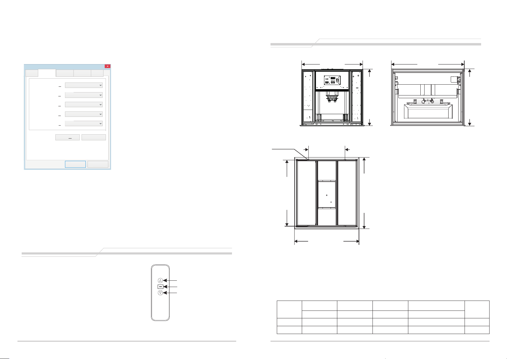
Rs485 P ort Settin g:
Bit Rate: 2400
Data bit: 8 bit
Odd check: N/A
Stopping position: 1
USB Serial Port (COM 3) 属性
端口设置
常规
常规 端口设置 驱动程序 详细信息 事件
驱动程序 详细信息
Baud Rat e:
位/秒(B) :
Baud Rat e:
Data Bit s:
数据位(D) :
奇偶校验(P):
Parity :
奇偶校验(P) :
Stop Bits:
停止位(S) :
Flow Con trol:
流控制(F) :
位/秒(B):
2400
数据位(D):
8
无
停止位(S):
1
流控制(F):
无
高级 A( )
高级
2400
8
无
1
无
( )
A
…
…
事件
还原默认值(R)
还原默认值(R)
Specifi cation
Front Vi ew
φ10mm
760mm 760mm
Detail in Parameter List
Side Vie w
453mm
Detail in Parameter List
取消
确定
确定
取消
Hexadecimal control code:
UP:ff,ee,ee,ee,dd
STOP:ff,ee,ee,ee,cc
DOWN:ff,ee,ee,ee,ee
Some center console need setting address:ff,ee,ee,ee,aa
Notice:
1.When connecting via RS232 or RS485, if any control fails, please switch two controlling cable.
2.Connecting Loop Resistance Tester should not be over 20Ω
3.Prohibit parallel line with strong interference source
Remote controller
Contr ol button in struc tion
1.Pres s UP to lift
2.Pres s STO P to stop
3.Pres s DOWN to lowe r
Front Vi ew
UP
STO P
DOWN
740mm
Screw Rod Installation Size
Produ ct size
Model
GPCD5804
GPCD5809
(W*D*H)mm (W*D)mm (W*D)mm (W*D*H)mm
760x760x 590 550x580x 240453x740 775x775
800mm
Model: GPCD58 Series
Biggest negative heavy:25kg
:
Ceiling Ho le Op eni ng Size
:
Screw R od In sta lla tio n Size
Ceiling door Dimension:
:
Rated Vo lta ge
:
Rated P owe r
Suitable for projector size:
800mm
Including wiring and lens
( )
The noise
Running speed:1m/min
Operation accuracy:<2mm
Control mode: weak electric dry contact, 485 Control
Required smallpox height:H+50mm
Mounti ng Ho le Ceiling opening size
:
≤55dB
775x775760x760x 860 550x580x 240453x740
220V 50Hz
800x800 mm
120W
Sugges tio n Pro jector
Size Ran ge
775x775 mm
453x740 mm
W550XD580XH240 mm
Quantity of
Telescopic
Arms
4
4
10
3
Page 6
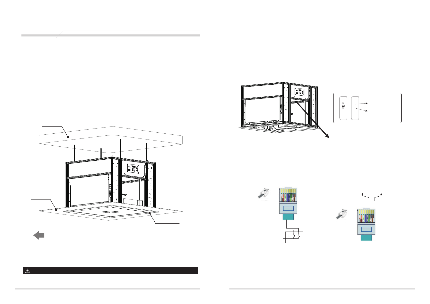
Installation
Insta llation in struc tions
This projector lift needs to be recessed into the ceiling,a nd th is in str uct ion t ake s the g ril le- cei lin g
as the example. Please install the projector lift according to diffe ren t app lic ati on. The projector lift
needs to be recessed at the best viewing angle in order to improve the image. Take ou t all t he pa rts
from the packaging and follow the installation instructions as below.
For the convenience and safety, ple ase r ead t his i nst ruc tio n man ual c are ful ly an d cho ose a
*
installation according to your requirement.
Concreted-Ceiling
Remote Localizer
When it is necessary to set the lower limit, open the electric double door. When the laminate reaches the ceiling,
press the pause button to use the keyhole on the back of the remote controlWhen the needle is inserted into the
blue light, the hanger will enter the preset state and reach the position required by the customer. Press the stop
button and insert the needle into the back of the remote control againWhen the small hole light is off and the
hanger moves slightly up and down once, the setting is completed.
light on enters preset
state
Insert a needle into
the hole
This sink plate will be automatically lowered down
when the light is on.
Ceiling la yer
Ceiling decoration frame
Pro jec tor Direc tion
(Note: C ontrol pa nel oppos ite d irec tio n project or direct ion)
(Installation diagram)
Warning: The top plate must be kept parallel when installing, otherwise it will cause damage to the lift.
安装时必须保证顶 板保持 水平,否则容易造成机械臂的损坏!
4
Central Control Instruction : requires a professional installation or contact us.
RS-485 plug: 7为+ / 8为-
5A 3B
Rj4 5 plug
down stop up
Central Control box
2
1 3 4 65 7 8
Rj4 5 plug
1
2
3
4
5
6
7
8
RJ45 wiri ng instru ction
Central control RJ45 plug
wiring instruction
NO.1 --GND
NO.2--DOWN
NO.3--STOP
NO.4--UP
others maintain
Rj4 5 plug
45 plug
485-RJ
wiring instruction
NO.7——join485A
NO.8——join接485B
others maintain
9
orange and white
、
orange
green and white
、
blue
blue and white
、
green
brown and white
brown
、
、
、
、
Page 7
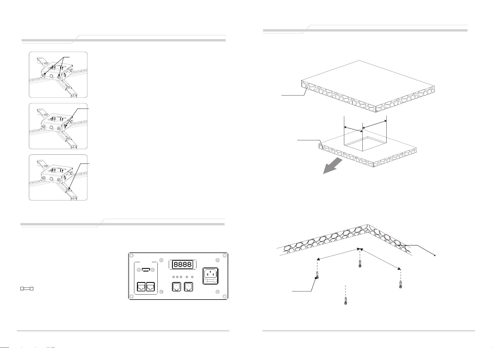
Angle adjustment
Rotate left and right ±3°
fig ure 1
fig ure 2
Rotate left and right
1.
Use a hex wrench to loosen the two screws on the front end.
As shown by the arrow in Figure 1, the universal joint can be
adjusted to the left and right by ±3°.
1° vertically upwards and 8° vertically downwards
vertical up and down adjustment
2.
As shown in Figure 2, use the hex wrench to loosen the two
screws on the left and right. The universal joint can be adjusted
vertically upward by 1° and vertically downward by 8°.
Installation steps
1.determine the direction of the projector and the installation position, according to the size
of the opening in the ceiling layer.
Concrete base
m
m
7
7
。
Ceilin g dec ora tive laye r
775
5
m
m
Adjust the length of the mounting feet
The installation foot adjustment
3.
Use a hex wrench to loosen the screws on the mounting feet.
As shown in Figure 3, adjust the screws to the desired length
fig ure 3
and retighten the screws.
Electrical, product instructions
Control panel description
Up: Electric hanger rises
Stop: electric hanger stops
Down: electric hanger drop
Communication port: Category 6 network port
Dry contact: dry contact interface RS485: RS485 interface
Power input: power input interface
Fuse: F6. 3A 250V
Reset: long press the reset button to adjust the height
Memory: electric hanger memory position height
HDMI 2.0: 19+1 2.0 HD interface
Digital display: electric hanger current screw telescopic height
INP UT
HDMI 2.0
CAT6 CAT6
CONTROLLER G1
up
stop
Down
Dry contact
Reset
RS-4 85
memory
IN- 220V
50H z 80W
Projection direction
2.Punch the concrete base and install the Tapping screws.
m
453m
Tapping screws
7
40mm
(Ceiling opening size diagram)
Concrete base
8
5
Page 8
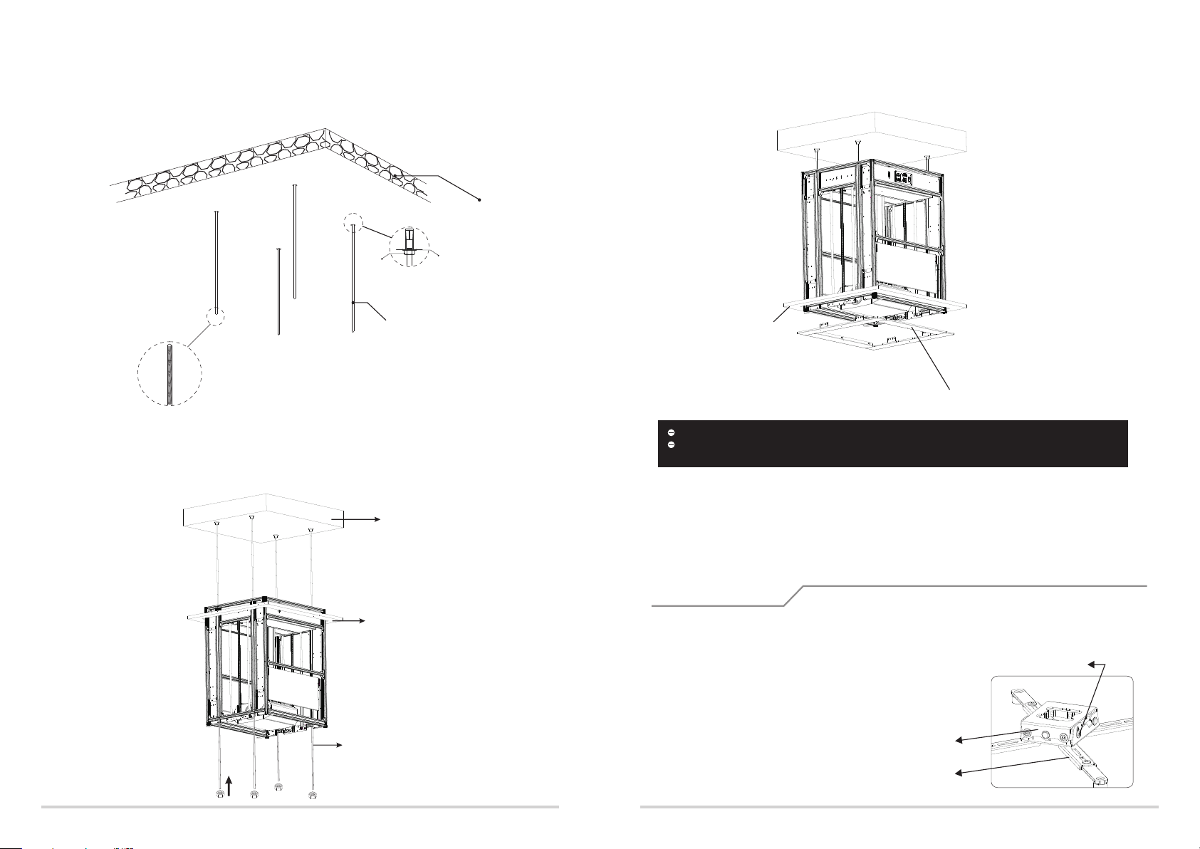
3.After checking that the tapping screw is fixed, install the screw rod and fix it. (In order to
make the screw rod easier to pass through the lifter, we recommend that the end of the
screw rod be tapered, and the length between each two lead rods can differ by 10-20mm.
Concrete base
5.Install the decorative frame so that the decorative frame fits on the ceiling layer and the
installation is completed.
Cushion
recommended to sharpen the end of the screw into
a taper that makes it easier to pass through the
screw hole of the lift
screw nut
screw rod
4.Lift the lifter to the height of the installation position by using the lifting equipment, and
pass the screw rod through the four holes of the lifter. Adjust the height of the lifter with the
screw nut so that it is flush with the height of the ceiling layer. Remove the excess screw rod.
Concrete base
Grille ceiling
Grille ceiling
make the decorative frame fits on the ceiling layer
Please note that you must touch the upper limit switch to stop the projector lift from rising!
The level above the electric lift must be adjusted to the level, Tilting can cause the electric hanger to
malfunction.
For the convenience of installation, the side plates of the cage can be removed first. After the installation is
completed, the installer can stand in the cage and reinstall the side panels. At this time, the side panels must
be turned over and installed.
If it is necessary to adjust the limit height due to the installation environment or the limitations of the site, it
must be adjusted by a special technician or call after-sales.
Projector installation
1. Lower the bamboo joint of the lift to the height suitable for the installer to install the projector, and remove
the mounting feet on the bamboo joint.
2. After the mounting feet are fixed on the projector, re-attach the projector and the mounting feet to the angle
adjuster and tighten the screws.
(Note: Be sure to confirm that the screws are securely locked, be
careful to prevent the projector from accidentally falling!)
Tighten the screws
screw nut
Screw rod
projector mounting Bracket
6
Angle adjuster
7
 Loading...