

Page 1
GRANDVIEW REPRODUCING GENUINE COLORS
GRANDVIEW REPRODUCING GENUINE COLORS
Installation Guide for
Portable Series X-Press
Screen
Grandview Crystal Screen Canada Ltd.
#11- 3751 North Fraser Way,
Marine Way Business Centre,
Burnaby, BC, Canada V5J 5G4
Tel: 1-604-412-9777 Fax: 1-604-412-9796
Website: www.grandviewscreen.ca
Guangzhou Grandview Crystal Screen Co., Ltd.
P.O. 511400 Federal Ind. Zone No. 363, Yushan West Road,
Shiqiao, Panyu District, Guangzhou, Guangdong, China
Tel: +8620-8489-9499 Fax: +8620-8480-3343
Website: www.grandviewscreen.com
ISO9001:2000
International Certification
Model: CB-UXxx
Thank you for purchasing a Grandview projection screen.
Before use, please read instructions carefully. After installation, store instructions for future reference.
Page 2
Description
Warning
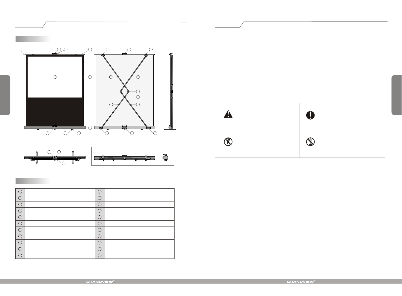
1
Illustration
Part name
34 75 6 8
1
13
Front view Back view
9
Top view
12
5
6
2
10
11
16
17
21
Screen retraction
1. Don't expose the screen in wind.
2. For the flatness of the fabric, remember:
9
a) Don't touch the screen surface with hands.
b) Don't write or draw on the screen surface.
C)
Don't poke screen fabric with finger or edge tools.
d) Clean the fabric with soft cloth and lukewarm water. Don't use any detergent or any diluent cleanser.
3. Lift up and retract the screen with even speed and force.
14
4. Retract fabric into the casing after display.
5. When retracting the screen, make sure the support lever joint is fasten into the support lever pipe.
6. Make sure the handle base is fastened and locked before carry.
18
19
15
22
20
Side view
7. In case of damage, the screen is recommended to be managed and operated by adults.
Ignoring the safety warnings may
lead to injuries and/or damaging
the product.
Retract the screen after every use.
Leave it hanging for a long period may
cause screen fabric loose
Please contact your local dealer for
repair s or maintenance. Please contact
Avoid hanging anything on the screen
as it may cause the screen to fall down.
our company if you have any further
questions. Avoid taking apart the
6
fixtures yourself. Loose parts may
cause the screen to fall.
Do not take apart and replace with unknown parts. If there are any problems, please contact your local dealer.
Product specifications are subject to change.
1
Fabric
2
Fabric black border
3
Semicircle tube
4
Rod
5
Tube lock
6
Handle
7
Left bracket
Right bracket
8
9
Handle base
Casing
10
11
Foot
12
Foot wheel
13
Front base
Support lever
14
Support lever
15
Support lever
16
Support lever
17
Support lever joint
18
Support lever pipe
19
20
Seat
21
Seat
22
Rear base
Page 3
Specifications
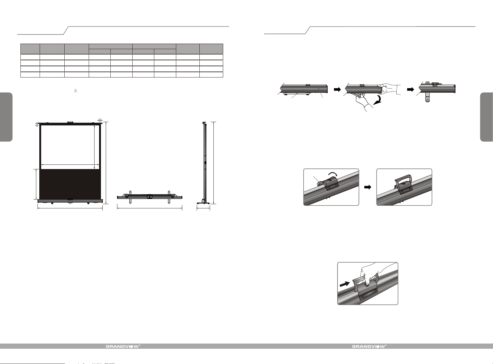
Open Screen
Format Model
4:3
CB-U70
16:9
CB-U80
CB-U70
CB-U80
Specification
(In)
70"
80"
70"
80"
Viewing area
W (mm) L (mm) H (mm) A (mm)
1422
1625 1220 1785 2553
1550 871 1710 2204
1770 995 1916 2328 28
1067 1582 2400
Screen dimension
Note: Sizes and specifications are subject to change at any time. Refer to real product for exact data.
The tolerance for L is 5mm.
5
25
W
800
L
Front view Top view
B1
H
A
L
B1 (mm)
Measurement unit: mm
Net weight
35
35
35
320mm
Side view
(kg)
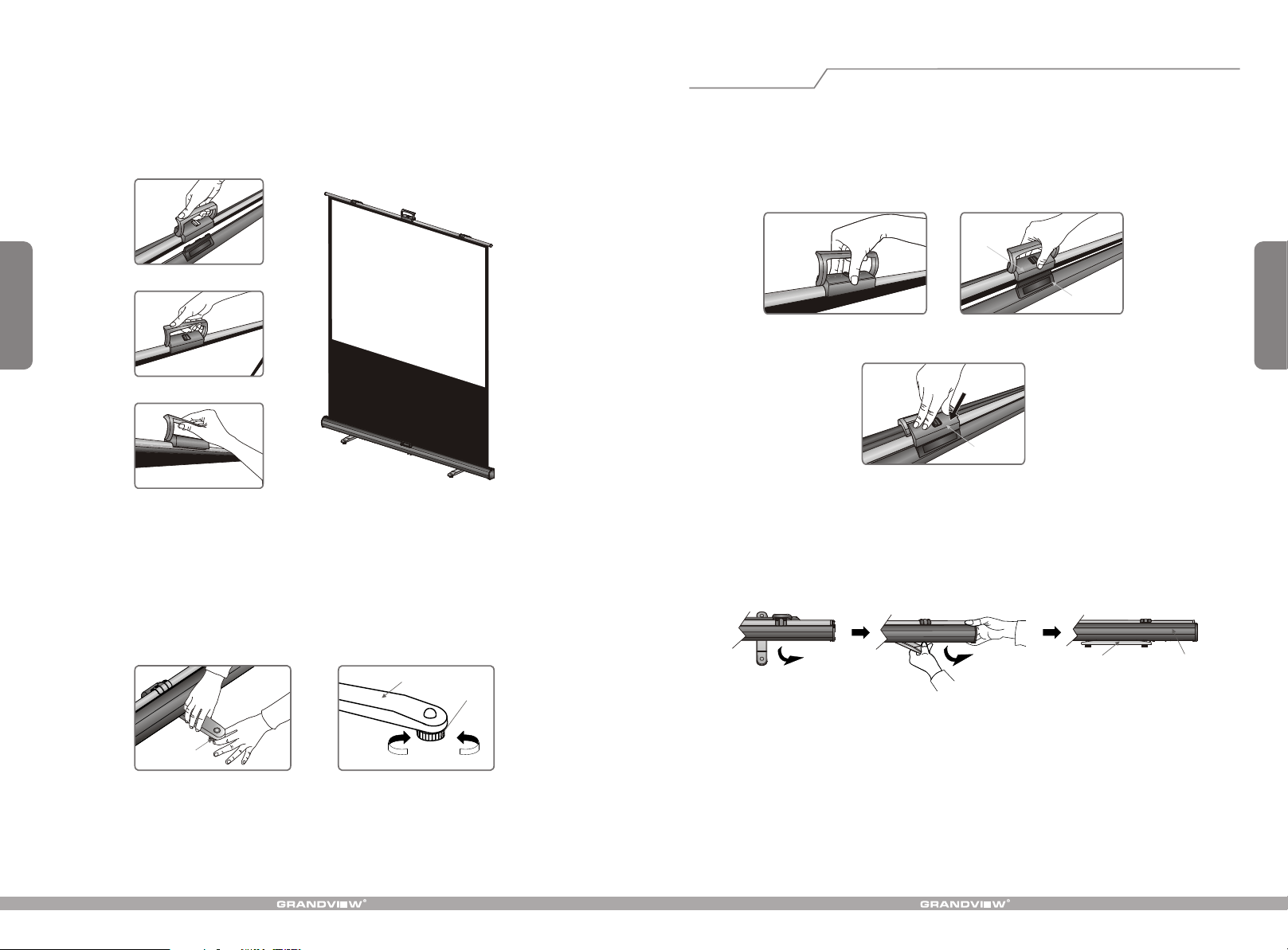
1. Put the screen on the ground, in a proper position facing the projector. Turn the feet out until they are
perpendicular to the screen casing . ( Figure 1 - 3 )
CasingFoot
Figure 1 Figure 2 Figure 3
2
2. Pull up the handle as the arrow indicates below .( Figure 4 - 5 )
A
Handle
Figure 4 Figure 5
3. Pull up the handle while using the thumb to release the tube lock as arrow indicates .( Figure 6 )
Figure 6
Page 4
Retract screen
4. Pull up the screen with constant speed and stop at desired position for three minutes so that the screen
can be installed .( Figure 7 - 10 )
Figure 7
3
Figure 8
Figure 9 Figure 10
5. Adjust the foot wheel when the ground is not even. To be exact, clockwise rotation raises the foot while
counterclockwise rotation lowers the foot, with limits of five circles or within 8mm . ( Figure 11 - 12 )
1. Grasp the handle and retract the screen into the casing till the handle base is firmly fastened in the tube lock
.( Figure 13 - 15 )
Handle base
Front base
4
Figure 13 Figure 14
Press gently
Handle base
Figure 15
2. Rotate the feet in line with the casing. Retraction is completed . ( Figure 16 - 18 )
foot wheel
Figure 11 Figure 12
Foot
foot wheel
Raise Lower
Foot
Figure 16 Figure 17 Figure 18
Casing
 Loading...