

Page 1
GRANDVIEW REPRODUCING GENUINE COLORS
ISO9001:2000
International Certification
Grandview Crystal Screen Canada Ltd.
#11- 3751 North Fraser Way,
Marine Way Business Centre,
Burnaby, BC, Canada V5J 5G4
Tel: 1-604-412-9777 Fax: 1-604-412-9796
Website: www.grandviewscreen.ca
Guangzhou Grandview Crystal Screen Co., Ltd.
P.O. 511400 Federal Ind. Zone No. 363, Yushan West Road,
Shiqiao, Panyu District, Guangzhou, Guangdong, China
Tel: +8620-8489-9499 Fax: +8620-8480-3343
Website: www.grandviewscreen.com
www.grandviewscreen.com.cn
GRANDVIEW REPRODUCING GENUINE COLORS
Thank you for purchasing a Grandview projection screen.
Before use, please read instructions carefully. After installation, store instructions for future reference.
Instruction Manual of
Mini Recessed Motorized Screen
Mo de l: CB -M RC
Page 2
Please read the below att ention points before using
1- 2m m >4 mm
Warnings
Adjustment
Warning
Constraint
Forbidden
1. Ple ase hand o ver the s creen to q ualified p rofessiona l for ins tallation, non-quali fied indiv idual cou ld cause d amage
to the pro duct or injury o f people.
2. Pl ease make sure th at the i nstallation positio n can su ffer from at least 50 Kg, otherwise there c ould be a potenti al
droppi ng problem caus ing damage to th e product or inj ury of people.
3. It is fo rbidden to connect the power befor e the inst allation is finished , oth erwise it could cause damage to the
produc t or injury of peo ple.
4. Wro ng wiring of malfun ction of t he wire co uld cause damage to the produ ct or inq uiry of pe ople, ple ase hand o ver
the elec tric work to ele ctric profess ionals.
5. The product is using Single-ph ase AC p ower, ple ase use a socket with earth wire an d make su re the e arth wire is
well con nected.
6. Pleas e make sure the sc reen is install ed in a level stat us, otherwis e it could cause d amage to the pro duct.
7. F or scree n with IR cont rol, ple ase do not use it in places with s trong li ght or laser. For scre en with remote control,
please do no t get close t o fluore scent l amp, led lamp or othe r device or e nvironment with strong e lectromagn etic
radiat ion, to avoid da mage to the produ ct.
8. In orde r to lower down th e possibilit y of fire or electr ic shock, plea se do not expose t he product in da mp places.
9. Pleas e keep the screen a way from heati ng device such a s heater, stov e, etc.
10. As long as t he plug is st ill in socket, the s creen i s still connect ed with AC po wer, pl ease rem ove the plug during
lighte ning, thunde rstorm or not us ed for extended p eriods.
11. Plea se retract the fa bric fully in th e case after usi ng to avoid dama ge to the fabric b y dust and dirt.
12. If the s urface of fabri c is dirty or bein g cut, it will aff ect the image qu ality, so plea se pay attenti on to below poin ts:
A. Pleas e do not touch the f abric with you r hand
B. Pleas e do not write or dra w on the fabric
C. Pleas e do not cut or poke t he fabric to avoi d damages
D. Pleas e do not clean the s urface with ch emical cleane r, you can use dry c loth and soap wa ter instead.
13. To avo id unnecessa ry damage, plea se use and manag e the product by a dult.
14. Plea se choose only t he accessori es from origin al factory.
15. Plea se do not hang any i tems under the ca se to avoid pote ntial damage s.
16. Ther e are no spare part s inside for rep lace or repair , please conta ct the after sal es team for afte r sales servic e.
17. Lubr icant is not req uired for the mot or.
Warning
Constraint
Warning
Warning
Warning
Warning
Warning
Warning
Warning
Warning
Warning
Warning
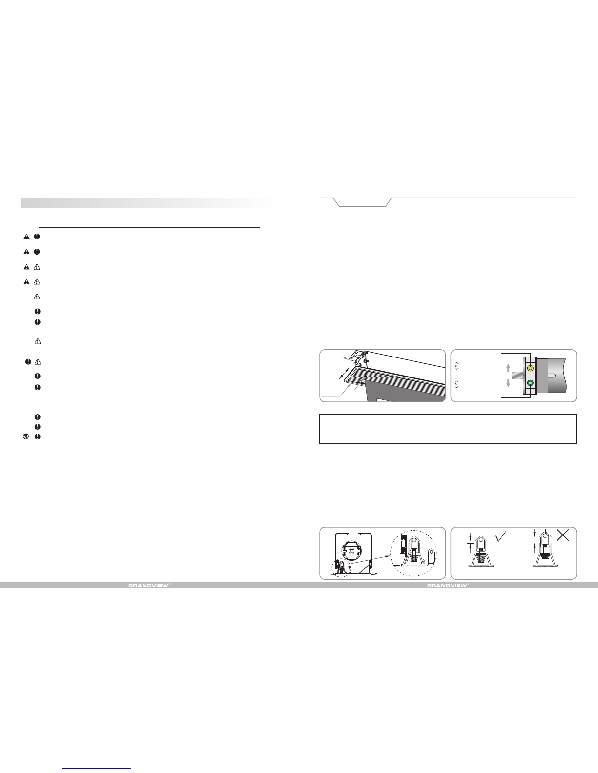
Instr uction of a djusting the retr action an d extension limit
1. The de fault retrac tion limits a re perfect set tings, we do no t recommend a djustment to a void potenti al damage to
the prod uct, please ta lk to after sale s team for furth er advice.
2. If y ou do need a djust the e xtension li mit, you ca n do that th rough the s lot underne ath the rig ht hand side of the
screen , with below ins tructions:
WARNI NG
Please pay attent ion wh en adj usting retractio n. Ove r-retracti on is avoide d in order not to s poil t he mot or and
screen ; pleas e also pay att ention when adj usting e xtension. The f abric sh ould be rolled at lea st one and a half
rounds onto the shaft to a void t he fab ric fa ll off . Afte r the adjust ment is done, the differe nce of retra ction and
extens ion limit migh t not be found at on ce until the scr een is operate d for several ti mes.
Adjus tment of re traction (upper l imit).
Press t he "up" butt on of the con troller and t he screen wo uld retract . When the fa bric rod goes nearby or en ters the
case, p lease inser t the adjuste r key (slight a djustment o n direction i s needed when i nsert adjus ter key until t he key
enter correctly into the g reen hole) into the p ositioner a djusting h ole in gre en color on motor to make adjust ment.
Stand opposite to pos itioner a djusting hole and turn a djuster key clock wise to make fa bric exte nd sligh tly, whil e
turn cou nter clockwi se to make fabri c a little retra ction for adju stment.
Note on u pper limi t adjustment:
The dec oration boa rd of this pr oduct can com pletely cov er the exit o f the case and there is spr ings instal led on the
integr ation of fabri c rod, which is di fferent from o ther series of s creens.
When a djusting t he upper li mit, pleas e make sure decoratio n board cou ld be comp letely clos ed. Enough space is
needed for decoratio n board to move fr eely. S etting the upp er limi t to be too high would come t o damag e the
fabric o r motor.
Adjus tment of ex tension (lower li mit).
Press the "dow n" button of the controller and the screen w ould exte nd. Inser t the adj uster key into th e positio ner
adjust ing hole in yellow color on motor to m ake adjus tment. Sta nd opposit e to posi tioner adj usting hol e and turn
adjust er key cloc kwise to ma ke fabric r etract slig htly, whil e turn coun ter clockwi se to make fabric a lit tle extens ion
for adju stment.
Due t o the spe cial stru cture of the produc t, defaul t of "r etraction limit" ha s been pe rfectly s et and it is not
recomm ended to m ake adjust ment by use r so as no t to damag e the scree n because of imp roper
adjust ment on retrac tion limit. An y damage out of th is operation i s not under warr anty for the pro duct.
Diagra m 32 Diagra m 33
Ceilin g bracket
Yellow k ey hole
Front
Rear
Positi on of extensio n ( lower limit)
Adjust cloc kwise to move upw ard
Adjust cloc kwise to move do wnward
Adjust coun ter clockwis e to
move upward
Adjust coun ter clockwis e to
move downwar d
Positi on of retracti on (upper limi t)
Green ke y hole
Left
decora tion
cap
Lower lim it
adjusti ng
hole
Front
Rear
Diagra m 34
Proper
height
Improp er
height
(upper
limit is s et
too high )
Status o f lower bar when r etraction
(seen fr om side view)
Diagra m 35
Page 3
AC 220 ~230V
50~6 0Hz,115 W
M
K1
78 mm
12 8m m
18
上升
停止
下降
上升
停止
下降
Accessories Pack(s)
Optional Accessories
Operation Instruction
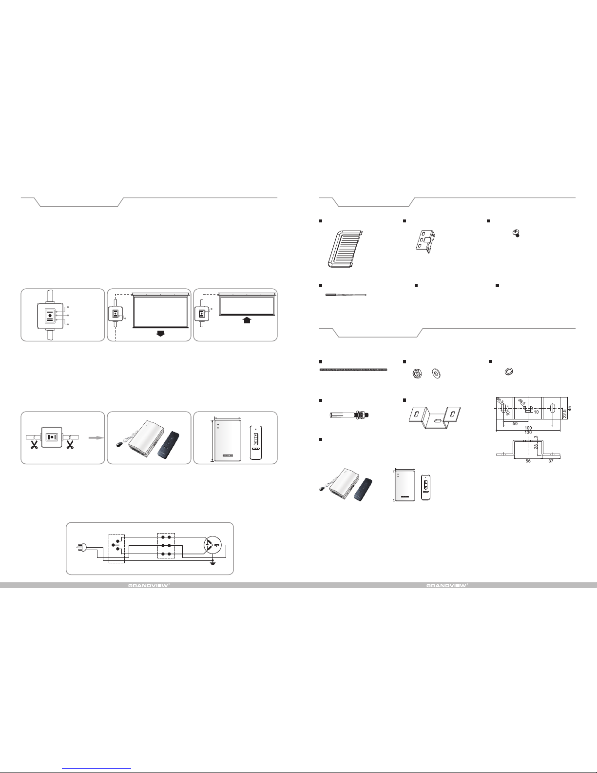
The moto rized screen i s standard wit h inline switc h control, whi le external re mote control i s for your optio n.
1. Inlin e switch cont rol (diagram 25 )
Extens ion (diagram 2 6) Press "down " button on inli ne switch then t he fabric woul d extend slowl y till it reache s
the defa ult position b efore it stops a utomatical ly.
Retrac tion (diagra m 27) Press "up" b utton on inlin e switch then th e fabric would r etract slowl y till it comple tely
enters t he case before i t stops automa tically.
Stop Pre ss "stop" butt on on inline swi tch in the cours e of retractio n or extension t o make
fabric s top at the posit ion required .
2. Exter nal remote con trol and RS232 /485 control :
If remot e control or RS2 32/485 contr ol is needed, pl ease upgrade t he control sys tem by install ing external r emote
contro l kits (need to cu t off the inline s witch and rein stall the exte rnal remote co ntrol kits man ually for alte rnative),
see diag ram 28-30. Ple ase turn to the ma nual for exter nal remote con trol kits to kno w more details o n usage and
wiring c onnection me thod.
Model av ailable: Ext ernal IR remot e control kits ( Third Genera tion)---Mo del: 1GD-IRA nⅢ
Extern al RF remote con trol kits (Thi rd Generatio n)—Model: 1G D-868MnⅢ.
;
Note:
Make sur e the fabric is cl ean before ret raction.
It is not re commended th at continuou s operation of r etraction or e xtension be ov er 50 seconds. O ver heat of the
motor du e to operated co ntinuously a bove 4 minutes w ould result th e screen in prot ection statu s (stop workin g for
a while) . In this situat ion, please st op operating t he screen for a mo ment until mot or is cool.
3. Circu it diagram
3. Circu it diagram
Decora tion cap*2 pcs
(left an d right)
Ceilin g bracket*2 pc s M5*10 th umb head screw *4 pcs
M4 hexag onal adjuste r key*1 pc
M8*500 e xtended bolt *2 pcs
M8*60 Ex pansion bolt *4 pcs
Spring g asket*6 pcs
Extern al remote cont rol kits ( with RS 232/485 cont rol function )
Extern al IR remote con trol kits (Thi rd Generation )---Model: 1 GD-IRAnⅢ;
Extern al RF remote con trol kits (Thi rd Generation )—Model: 1GD -868MnⅢ.
Hook*2 pcs
Dimens ion for instal lation of hook
M8 nut*8 p cs, gasket*8 p cs
Qualif ication cert ificate*1 co py Manual *1 set
Diagra m 25
Up
Stop
Down
Diagra m 27Diagra m 26
Down
Up
Diagra m 28 Diagra m 30
Diagra m 31
Diagra m 29
Up
Common
Down
Yellow g reen
Brown
Blue
Black
78m m
128 mm
Page 4
72
Product structure Installation Instruction
Case
Instal lation plate
Right tr estle
Right ca p
Left tre stle
Power li ne
Left cap
Limit
adjust ing
Fabric
Instal lation plate
Instal lation
plate
Power li ne
Left cap
lower li mit
adjust ing hole
Mounti ng hole
Left cap
Fabric r od
integr ation
Instal lation plate
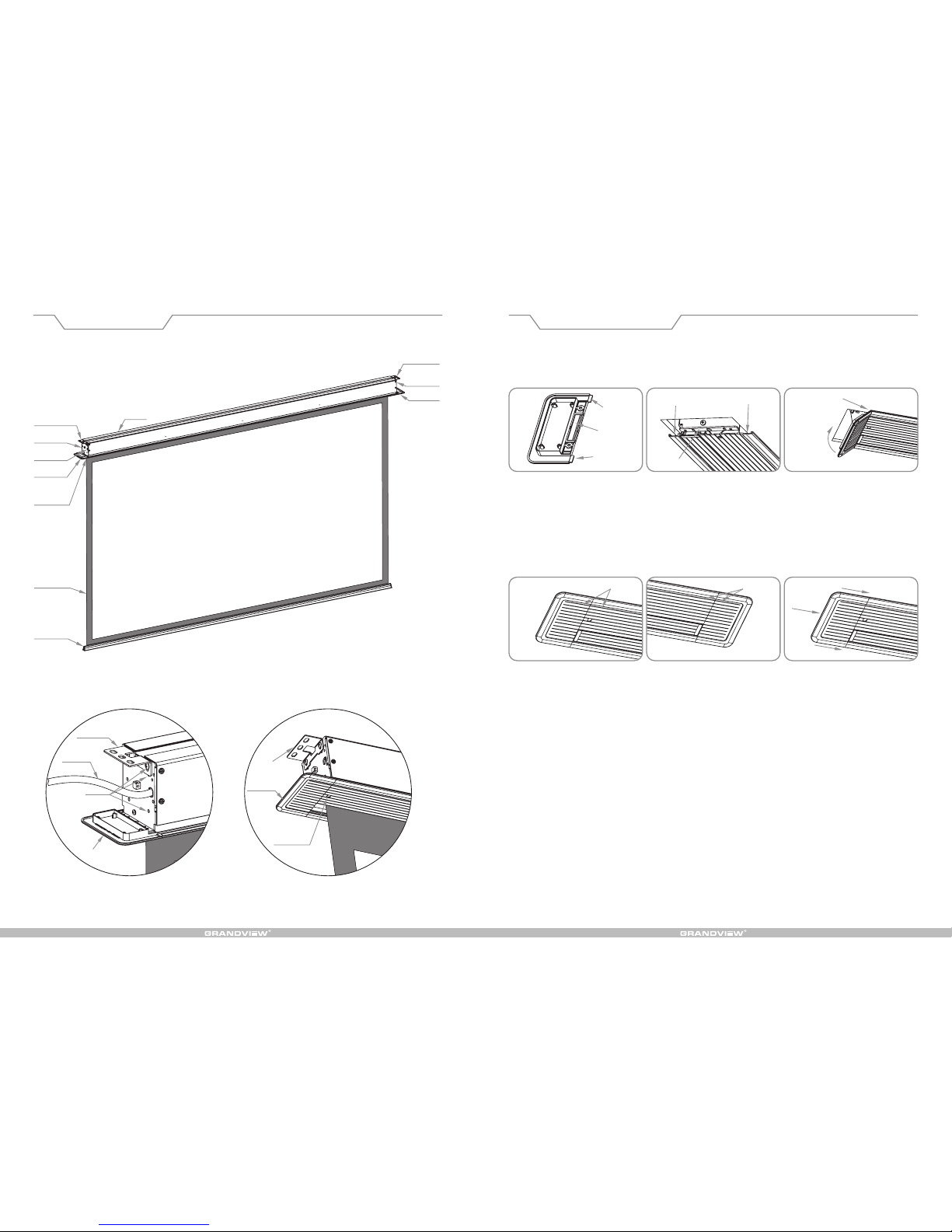
10. Installati on of left/right decorat ion cap. Insert the fix ing legs (diagra m 19) of decor ation ca p aslope into s lots
from th e two edges of de coration boa rd (diagram 20 ). Please pus h upward tight ly (diagram 2 1) and the decor ation
cap woul d be attached to l eft/right tr estles by magn et (see diagra m 19-21).
Note:
Please make it clear the left and right decorat ion ca ps. P lease pay attention to the decoratio n str ip. A fter the
decora tion caps are f ixed, the de coration str ips should be i n line with th ose on the deco ration boar d (diagram 22 -
23)
If the sea m seems too big at t he joint, plea se push the deco ration cap tow ard the screen t o make it in posit ion.
Fixing l eg
Slot
1.Inse rtion into slo t
2.Push
upward
tightl y
left/r ight
trestl es
Slot
Magnet
Fixing l eg
Decora tion strips in l ine Decora tion strips in l ine
Push the m iddle forwar d if seam is
too big at
the join t
Left dec oration cap Right de coration cap
Diagra m 19
Diagra m 22
Diagra m 21
Diagra m 24
Diagra m 20
Diagra m 23
Page 5
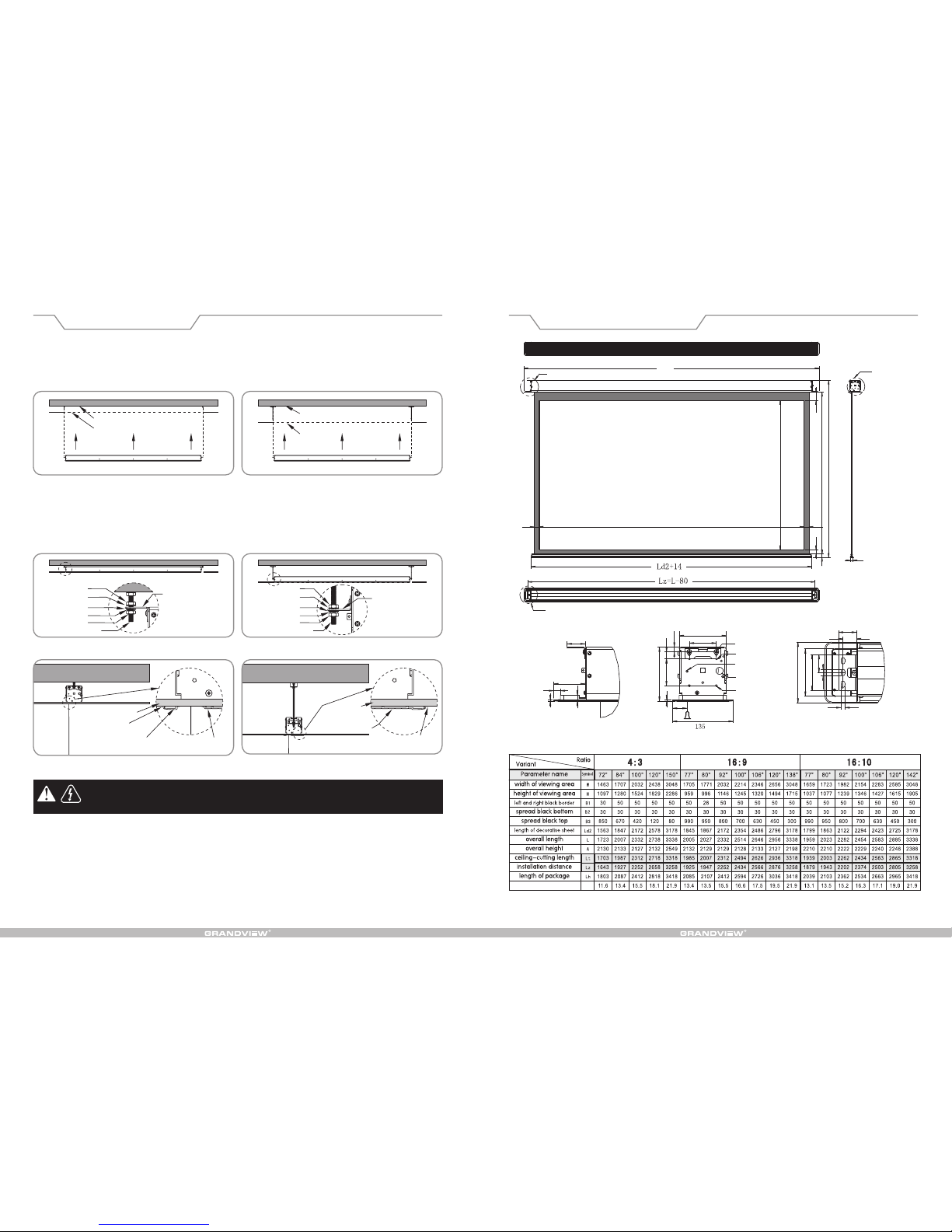
W
H
B1 B1
B3 B2
A
34
30
Ht=H+B2+B3
14
15
70
4
40
40
30
105
135
80
40
8.5
14.5
105
60
15
60
10.5
120
4
36
Installation Instruction Framework and Dimension
6. Li ft the s creen and put it into the mounting holes p re-drilled. The fix ing holes on two ends of installat ion plate
should a lign to the expa nsion bolts or e xtended bolt s on ceiling, se e diagram 13-1 4.
Note: Thi s st ep m ust be completed by two insta llers who should hold two end s o f sc reen respectiv ely when
instal lation.
7. Please put gasket, spring gasket and nut through the b olt, t wist t he nut for several round s but not fasten it
(diagr am 15-1 6), and adjust the po sition o f the nuts a bove and below the in stallation plate to get the front an d
back part of deco ration board close eno ugh to t he d ecoration ceil ing. Then please faste n th e nu t be low the
instal lation plate , see diagram 15 -18.
Warnin g:
Any ins tallation o f the screen re lated to ele ctrical oper ation must be done by quali fied electr ician,
or it is lik ely to damage th e product or pro perty lost and c asualty.
Note:
Before connecti ng the p roducts to power s upply, ple ase make sure the put-in v oltage is in confo rmity wit h rated
voltag e of the prod uct. It is re commended that supply p ower sho uld be 2 time s or above as much as the rated
power of t he product. An y improper pow er supply woul d lead to abnorm al performan ce or even spoil t he product.
8. Ple ase fix the i nline switc h or externa l remote con trol receiv ing box wher e it is conve nient to ge t access to. Then
plug in th e socket to conn ect to power sup ply.
9. Ope rate the scr een to compl ete retract ion and exte nsion for o nce or twice to see if it is working n ormally bef ore
moving t o next step of ins tallation.
Note:T he screen m ust be opera ted in leve l condition . Please mak e necessar y adjustmen t for screen to be
horizo ntal when inst alling, or it wo uld be likely to d o damage to the sc reen.
Concre te ceiling
Mounti ng hole
Lift upw ard
Fabric
Nut
Decora tion ceiling
Decora tion ceiling
Back par t of
decora tion board
Front pa rt of
decora tion board
Front pa rt of
decora tion board
Adjust t o be flat
and smoo th
Adjust t o be flat
and smoo th
Nut
Instal lation plate
Instal lation plate
Nut Nut
Expans ion bolt Extend ed bolt
Gasket Gasket
Gasket Gasket
Spring g asket Spring g asket
Fabric
Mounti ng hole
Lift upw ard
Concre te ceiling
L
Check to d etails A
Check to d etails B
Check to d etails C
Instal lation dista nce: Lz=over all length(L )-80mm
Ceilin g-cutting di mension: len gth (Lt)=ove rall length( L)-20, 115mm i n width, 120mm p lus in height
Electr ical data: AC2 20-230V/50 -60Hz, 0.48A , 115W.
Any cha nge on functio n, structure or s pecificati on is without pr ior notice due t o improvemen ts on the produc t.
Please r efer to the spec ific product i ncluded.
Detail s B
Detail s A
Detail s C
Mounti ng hole-1
Mounti ng hole-2
GND hole
Power ca ble
Mounti ng hole-3
33(reference range
changed according
to height of fabric)
Diagra m 13 Diagra m 14
Diagra m 15
Diagra m 17
Diagra m 16
Diagra m 18
Gross Weight (kg)
Page 6
H
H
54
Installation Instruction Installation Instruction
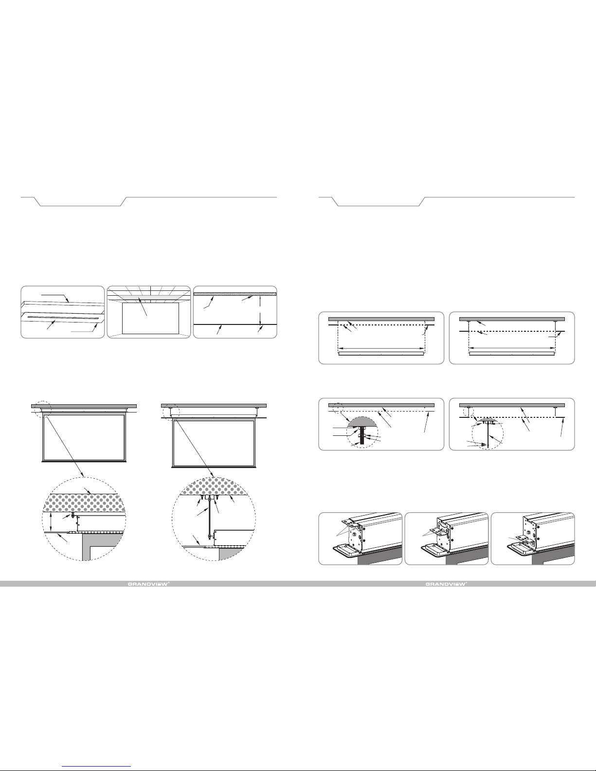
This p roduct is fi t to instal l into all t ypes of dec oration cei lings. User could inst all the pro duct accord ing to diff erent
enviro nments. Th e screen sho uld be inst alled at the most proper place wher e it can work with proje ctor. It is m ore
conven ient and safer f or use when the sc reen is instal led right and co rrectly.
Please unpack th e packages and check if the fitt ings are c orrect in n umber and types. Plea se install the scree n at
proper p lace accordi ng to the instal lation instr uctions belo w.
1.Ceil ing-cuttin g should be don e at the positio n where the scr een would be ins talled (diag ram 1). The dime nsion of
ceilin g-cutting is 115mm in widt h, while it is 2 0mm short er than the overa ll length . As to the gril le ceilin g, please
take some piece s out of the ceilin g (di agram 2) a nd cu t th em in to pi eces that would fit to t he ce iling for reinstal lation after i nstallatio n of the screen is f inished.
2.Plea se measure the heigh t between s urfaces of concrete ceiling and decoratio n ceiling (diagram 3 ) for optio nal
instal lation modes :
A. If the “H ” is about 120mm , please insta ll the screen di rectly onto co ncrete ceili ng, see diagra m 4;
B. If the “H ” is above 120mm , optional acc essories inc luding the hoo k and extended b olt are needed
to compl ete installa tion, see diag ram 5.
Concre te ceiling
Ceilin g-cutting
Concre te ceiling
Expans ion bolt
Concre te ceiling
Extend ed bolt
(optio nal
access ory)
Extend ed bolt
and hook
(optio nal accessor y)
Expans ion
bolt
Decora tion
ceilin g
Screen
Diagra m 4 For installa tion to low ceil ing Diagra m 5 For installa tion to high cei ling
Diagra m 1
Screen
Decora tion ceiling
Removi ng some pieces
of decor ation ceilin g
Surfac e of ceiling
Surfac e of
decora tion ceiling
Decora tion ceiling
Concre te ceiling
Diagra m 2 Diagra m 3
Decora tion
ceilin g
Note: Pleas e make sure the concret e cei ling i s str ong en ough t o be bear the weight of 50kg or abo ve be fore
starti ng in stallation in order to avoid any damage on product or property lost and casualty due to insuffic ient
bearin g.
Note: Ins tallation of the pro duct must be complet ed b y q ualified tech nician(s), or it wou ld r esult in damage,
proper ty lost and casu alty.
3.According to the installation mod es, please dr ill holes on concrete ceil ing and fix e xpansion bolt (
not i ncluded) in m odel of M8*80 or longer one into the holes, see d iagram 6 and 8; for high ceil ing
insta llation , hooks and extended bolts are needed to work with M8*60 expansi on blot (optional
acces sories) , see diagram 7 and 9;
4.Both of the inst allation modes nee d to put the ext ra M 8 nu ts a nd g askets for adjustm ent on t he h eight of
instal lation, see di agram 8-9;
5.Choo se the set s of mount ing holes f or fixture according to the ins tallation mode select ed. Please use the M5 *10
screws included i n fitting pa ck to fix the screen. If t he extended bolts are no t needed in i nstallatio n, please ch oose
the fi rst set o f mounting holes for fixture, see diagra m 10; for installati on to high ceiling w here exten ded bolts are
applie d, please choose the seco nd o r th ird set of m ounting holes acc ording to installa tion environme nt. It i s
recomm ended to cho ose the thir d set of mount ing holes if the extended bolts are lo ng enough to r each becaus e it
is easie r for installa tion, see diag ram 11-12.
Note: Th e center dist ance of two hol es drilled for s uspending p urpose shoul d strictly fo llow the actua l dimension o f the product , or the
instal lation i s not likely to be done; th e dista nce from the t wo hole s drille d for suspending purpos e to b oth ends of t he decor ation
ceilin g should be the same. The suspendi ng (insta llation) distance equals o verall le ngth of screen mi nus 80mm, please refer to the
specif ication diag ram for details .
Concre te ceiling
Concre te ceiling
Ceilin g-cutting (s lot)
Ceilin g-cutting (s lot)
Suspen ding (instal lation) dist ance Suspen ding (instal lation) dist ance
Decora tion
ceilin g
Decora tion
ceilin g
Diagra m 6 Use screws for i nstallatio n to low ceiling Diagra m 7 Use hook for ins tallation to h igh ceiling
Gasket
Spring g asket
Nut
Expans ion bolt
Nut
Nut
Concre te ceiling
Expans ion
bolt
Hook and
bolt
(optio nal
access ory)
Concre te ceiling
Ceilin g-cutting
(slot)
Extend ed bolt
(optio nal accessor y)
Ceilin g-cutting
(slot)
Decora tion ceiling
The firs t set
of mount ing
holes
The seco nd set
of mount ing
holes
The thir d set
of mount ing
holes
Gasket
Gasket
Diagra m 8 Use screen for i nstallatio n to low ceiling
Diagra m 10 Diagra m 12Diagra m 11
Diagra m 9 Use hook for ins tallation to h igh ceiling
Decora tion
ceilin g
 Loading...