

Page 1

CALLROUTES
OUTBOUNDROUTES
In the UCM6200, an outgoing calling rule pairs an extension pattern with a trunk used to dial the pattern.
This allows different patterns to be dialed through different trunks (e.g., "Local" 7-digit dials through a FXO
while "Long distance" 10-digit dials through a low-cost SIP trunk). Users can also set up a failover trunk to
be used when the primary trunk fails.
Go to Web GUI->PBX->Basic/Call Routes->Outbound Routes to add and edit outbound rules.
Click on "Create New Outbound Rule" to add a new outbound route.
Click on
Click on
On the UCM6200, the outbound route priority is based on “Best matching pattern”. For example, the
UCM6200 has outbound route A with pattern 1xxx and outbound route B with pattern 10xx configured.
When dialing 1000 for outbound call, outbound route B will always be used first. This is because
pattern 10xx is a better match than pattern 1xxx. Only when there are multiple outbound routes with
the same pattern configured, users can click on
arrange the priority among those outbound routes.
Calling Rule Name
Pattern
to edit the outbound route.
to delete the outbound route.
to move the outbound route up/down to
Table 56: Outbound Route Configuration Parameters
Configure the name of the calling rule (e.g., local, long_distance, and etc).
Letters, digits, _ and - are allowed.
All patterns are prefixed with the "_".
Special characters:
X: Any Digit from 0-9.
Z: Any Digit from 1-9.
N: Any Digit from 2-9.
".": Wildcard. Match one or more characters.
"!": Wildcard. Match zero or more characters immediately.
Example: [12345-9] - Any digit from 1 to 9.
Password
Call Duration Limit
Firmware Version 1.0.0.1 UCM6200 Series IP PBX User Manual Page 170 of 320
Configure the password for users to use this rule when making outbound
calls.
Enable to configure the maximum duration for the call using this outbound
route.
Page 2

Maximum Call Duration
Warning Time
Warning Repeat Interval
Privilege Level
Configure the maximum duration of the call (in seconds). The default
setting is 0, which means no limit.
Configure the warning time for the call using this outbound route. If set to
x seconds, the warning tone will be played to the caller when x seconds
are left to end the call.
Configure the warning repeat interval for the call using this outbound
route. If set to x seconds, the warning tone will be played every x seconds
after the first warning.
Select privilege level for the outbound rule.
Internal: The lowest level required. All users can use this rule.
Local: Users with Local, National, or International level are allowed to
use this rule.
National: Users with National or International level are allowed to use
this rule.
International: The highest level required. Only users with international
level can use this rule.
Disable: The default setting is "Disable". If selected, only the matched
source caller ID will be allowed to use this outbound route.
Please be aware of the potential security risks when using "Internal" level,
which means all users can use this outbound rule to dial out from the
trunk.
Enable Filter on Source
Caller ID
When enabled, users could specify extensions allowed to use this
outbound route. "Privilege Level" is automatically disabled if using
"Enable Filter on Source Caller ID".
The following two methods can be used at the same time to define the
extensions as the source caller ID.
1. Select available extensions/extension groups from the left to the right.
This allows users to specify arbitrary single extensions available in
the PBX.
2. Custom Dynamic Route: define the pattern for the source caller ID.
This allows users to define extension range instead of selecting them
one by one.
All patterns are prefixed with the "_".
Special characters:
X: Any Digit from 0-9.
Z: Any Digit from 1-9.
N: Any Digit from 2-9.
".": Wildcard. Match one or more characters.
"!": Wildcard. Match zero or more characters immediately.
Firmware Version 1.0.0.1 UCM6200 Series IP PBX User Manual Page 171 of 320
Page 3

Send This Call Through Trunk
Example: [12345-9] - Any digit from 1 to 9.
Use Trunk
Strip
Prepend
Use Failover Trunk
Failover Trunk
Select the trunk for this outbound rule.
Allows the user to specify the number of digits that will be stripped from
the beginning of the dialed string before the call is placed via the selected
trunk.
Example:
The users will dial 9 as the first digit of a long distance calls. However, 9
should not be sent out via analog lines and the PSTN line. In this case, 1
digit should be stripped before the call is placed.
Specify the digits to be prepended before the call is placed via the trunk.
Those digits will be prepended after the dialing number is stripped.
Failover trunks can be used to make sure that a call goes through an
alternate route, when the primary trunk is busy or down. If "Use Failover
Trunk" is enabled and "Failover trunk" is defined, the calls that cannot be
placed via the regular trunk may have a secondary trunk to go through.
Example:
The user's primary trunk is a VoIP trunk and the user would like to use the
PSTN when the VoIP trunk is not available. The PSTN trunk can be
configured as the failover trunk of the VoIP trunk.
Allows the user to specify the number of digits that will be stripped from
the beginning of the dialed string before the call is placed via the selected
trunk.
Strip
Example:
The users will dial 9 as the first digit of a long distance calls. However, 9
should not be sent out via analog lines and the PSTN line. In this case, 1
digit should be stripped before the call is placed.
Prepend
Specify the digits to be prepended before the call is placed via the trunk.
Those digits will be prepended after the dialing number is stripped.
INBOUNDROUTES
Inbound routes can be configured via Web GUI->PBX->Basic/Call Routes->Inbound Routes.
Click on "Create New Inbound Rule" to add a new inbound route.
Click on "Blacklist" to configure blacklist for all inbound routes.
Click on
to edit the inbound route.
Firmware Version 1.0.0.1 UCM6200 Series IP PBX User Manual Page 172 of 320
Page 4

Click on to delete the inbound route.
INBOUNDRULECONFIGURATIONS
Table 57: Inbound Rule Configuration Parameters
Trunks
DID Pattern
Prepend Trunk Name
Alert-Info
Inbound Multiple Mode
Select the trunk to configure the inbound rule.
All patterns are prefixed with the "_".
Special characters:
X: Any Digit from 0-9.
Z: Any Digit from 1-9.
N: Any Digit from 2-9.
".": Wildcard. Match one or more characters.
"!": Wildcard. Match zero or more characters immediately.
Example: [12345-9] - Any digit from 1 to 9.
The pattern can be composed of two parts, divided by a ‘/’ character.
The first part is used to specify the dialed number the second part is
used to specify the caller ID and it is optional, if set it means only the
extension with the specific caller ID is allowed to call in or call out.
For example, patter '_2XXX/1234' means the only extension with the
caller ID '1234' is allowed to use this rule.
Prepend trunk name to display
Configure the Alert-Info, when UCM6200 receives an INVITE request, the
Alert-Info header field specifies an alternative ring tone to the UAS.
Multiple mode allows user to switch between destinations of the inbound
rule by feature codes. Configure related feature codes in the “Feature
Codes” page. If this option is enabled, user can use feature code to
switch between different destinations.
Select the default destination for the inbound call.
Extension
Voicemail
Conference Room
Queue
Default Destination
Ring Group
Paging/Intercom
Voicemail Group
Fax
DISA
IVR
Dial By Name
Firmware Version 1.0.0.1 UCM6200 Series IP PBX User Manual Page 173 of 320
Page 5

External Number
By DID
When "By DID" is used, the UCM6200 will look for the destination
based on the number dialed, which could be local extensions,
conference, call queue, ring group, paging/intercom group, IVR,
voicemail groups and Fax extension as configured in "DID
destination". If the dialed number matches the DID pattern, the call
will be allowed to go through.
Strip
Prepend
Dial Trunk
DID Destination
Configure the number of digits to be stripped from the beginning of the
DID. This option shows up only when "By DID" is selected.
Configure the number of digits to be prepended to an inbound DID
pattern, with strip taking precedence over prepend.
This option shows up only when "By DID" is selected. If enabled, the
external users dialing in to the trunk via this inbound route can dial
outbound call using the UCM6200’s trunk.
This option shows up only when "By DID" is selected. This controls the
destination that can be reached by the external caller via the inbound
route. The DID destination are:
Extension
Conference
Call Queue
Ring Group
Paging/Intercom Groups
IVR
Voicemail Groups
Fax Extension
Dial By Name
All
Time Condition
Time Conditions
Destination
Select the time condition for the inbound rule.
Select the destination for the inbound call during the specified time
condition.
INBOUNDROUTE:PREPENDEXAMPLE
UCM6200 now allows user to prepend digits to an inbound DID pattern, with strip taking precedence over
prepend. With the ability to prepend digits in inbound route DID pattern, user no longer needs to create
multiple routes for the same trunk in order to route calls to different extensions.
Firmware Version 1.0.0.1 UCM6200 Series IP PBX User Manual Page 174 of 320
Page 6
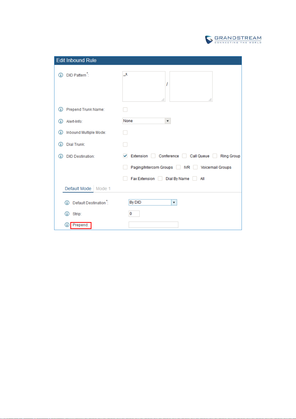
Figure 104: Inbound Route feature: Prepend
The following example demonstrates the process,
1. If Trunk provides a DID pattern of 18005251163.
2. If Strip is set to 8, UCM6200 will strip the first 8 digits.
3. If Prepend is set to 2, UCM6200 will then prepend a 2 to the stripped number, now the number
become 2163.
4. UCM6200 will now forward the incoming call to extension 2163.
INBOUNDROUTE:MULTIPLEMODE
In the UCM6200, the user can configure inbound route to enable multiple mode to switch between different
destinations. The inbound multiple mode can be enabled under Inbound Route settings.
Firmware Version 1.0.0.1 UCM6200 Series IP PBX User Manual Page 175 of 320
Page 7
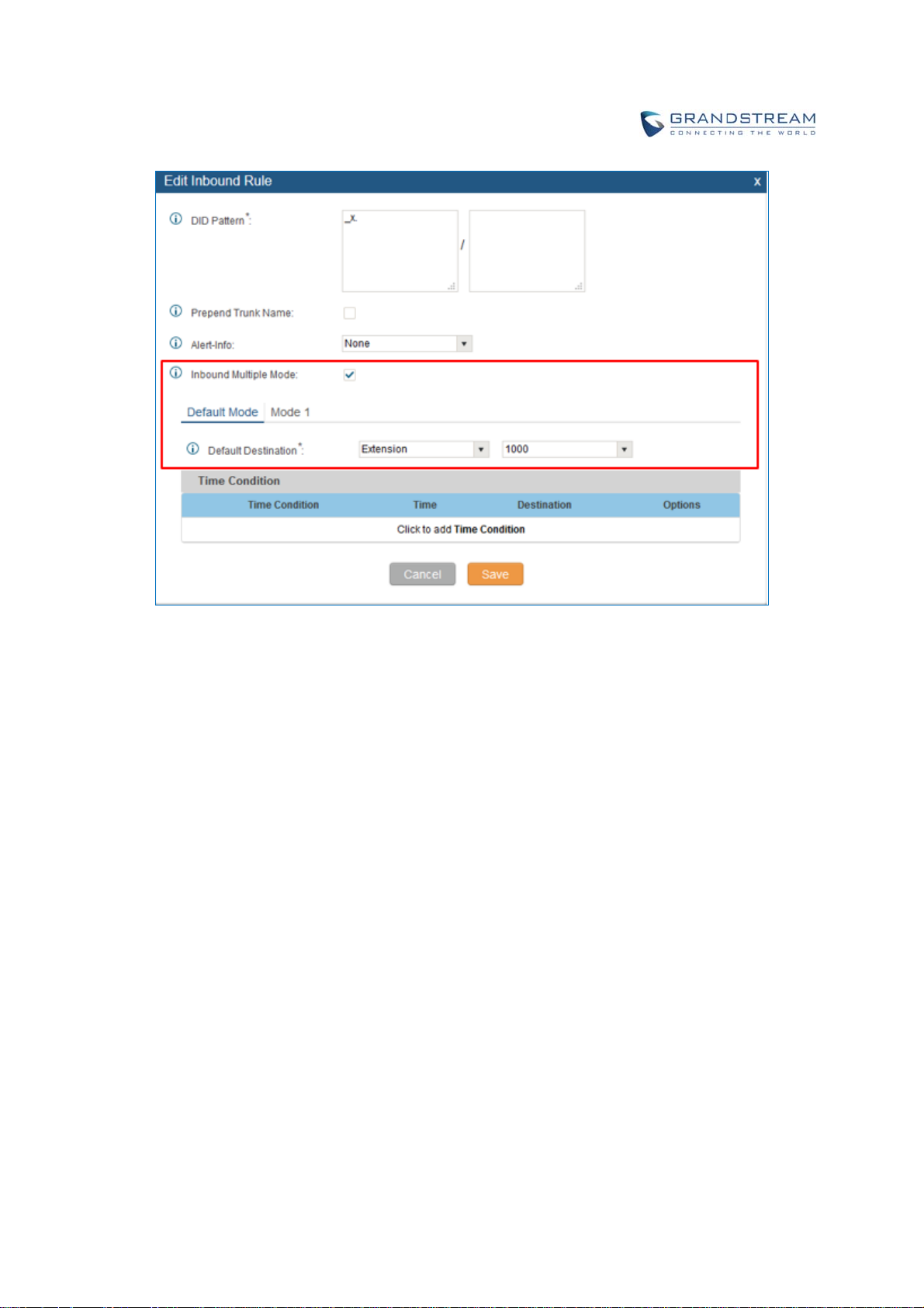
Figure 105: Inbound Route - Multiple Mode
When Multiple Mode is enabled for the inbound route, the user can configure a “Default Destination” and a
“Mode 1” destination for this route. By default, the call coming into this inbound route will be routed to the default
destination.
SIP end devices that have registered on the UCM6200 can dial feature code *62 to switch to inbound route
“Mode 1” and dial feature code *61 to switch back to “Default Destination”. Switching between different mode
can be easily done without web UI login.
For example, the customer service hotline destination has to be set to a different IVR after 7PM. The user can
dial *62 to switch to “Mode 1” with that IVR set as the destination before off work.
FAXINTELLIGENTROUTE
The UCM6200 can automatically detect Fax and phone signal coming from the FXO port, and then forward Fax
or phone signal to the right destination. For example, when a regular phone call is coming, the UCM6200 will be
able to detect the phone signal and forward it through the correct inbound route to the destination; if Fax signal is
coming, the UCM6200 will be able to forward it to the FXS extension where the Fax machine is connected.
Firmware Version 1.0.0.1 UCM6200 Series IP PBX User Manual Page 176 of 320
Page 8
FAXWITHTWOMEDIA
The UCM6200 supports Fax re-invite with multiple codec negotiation. If a Fax re-invite contains both T.38 and
PCMA/PCMU codec, UCM6200 will choose T.38 codec over PCMA/PCMU.
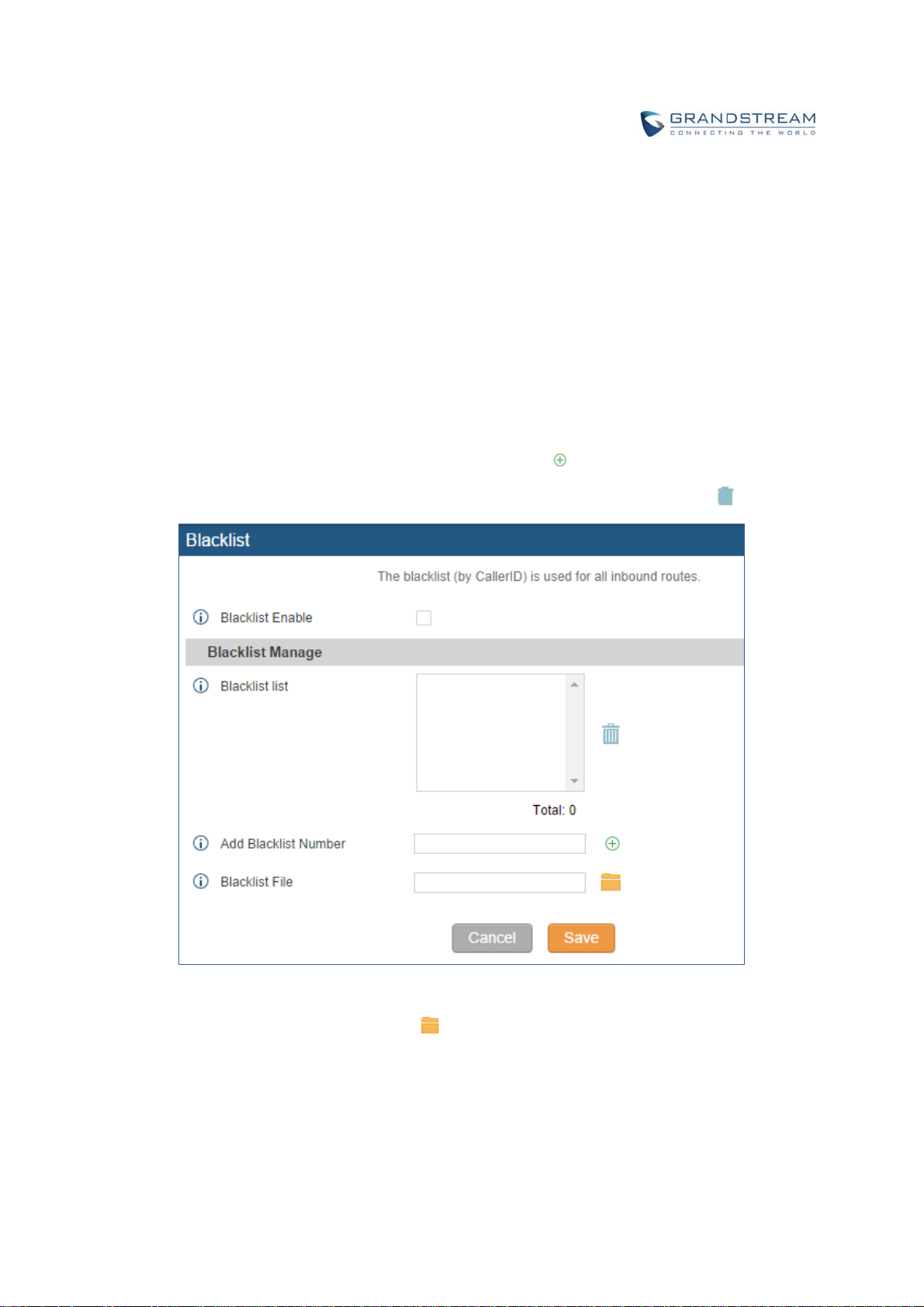
BLACKLISTCONFIGURATIONS
In the UCM6200, Blacklist is supported for all inbound routes. Users could enable the Blacklist feature and
manage the Blacklist by clicking on "Blacklist".
Select the checkbox for "Blacklist Enable" to turn on Blacklist feature for all inbound routes. Blacklist is
disabled by default.
Enter a number in "Add Blacklist Number" field and then click
to add to the list.
To remove a number from the Blacklist, select the number in "Blacklist list" and click on
.
Figure 106: Blacklist Configuration Parameters
To add blacklist number in batch, click on
to upload blacklist file in csv format. The supported csv
format is as below.
Firmware Version 1.0.0.1 UCM6200 Series IP PBX User Manual Page 177 of 320
Page 9
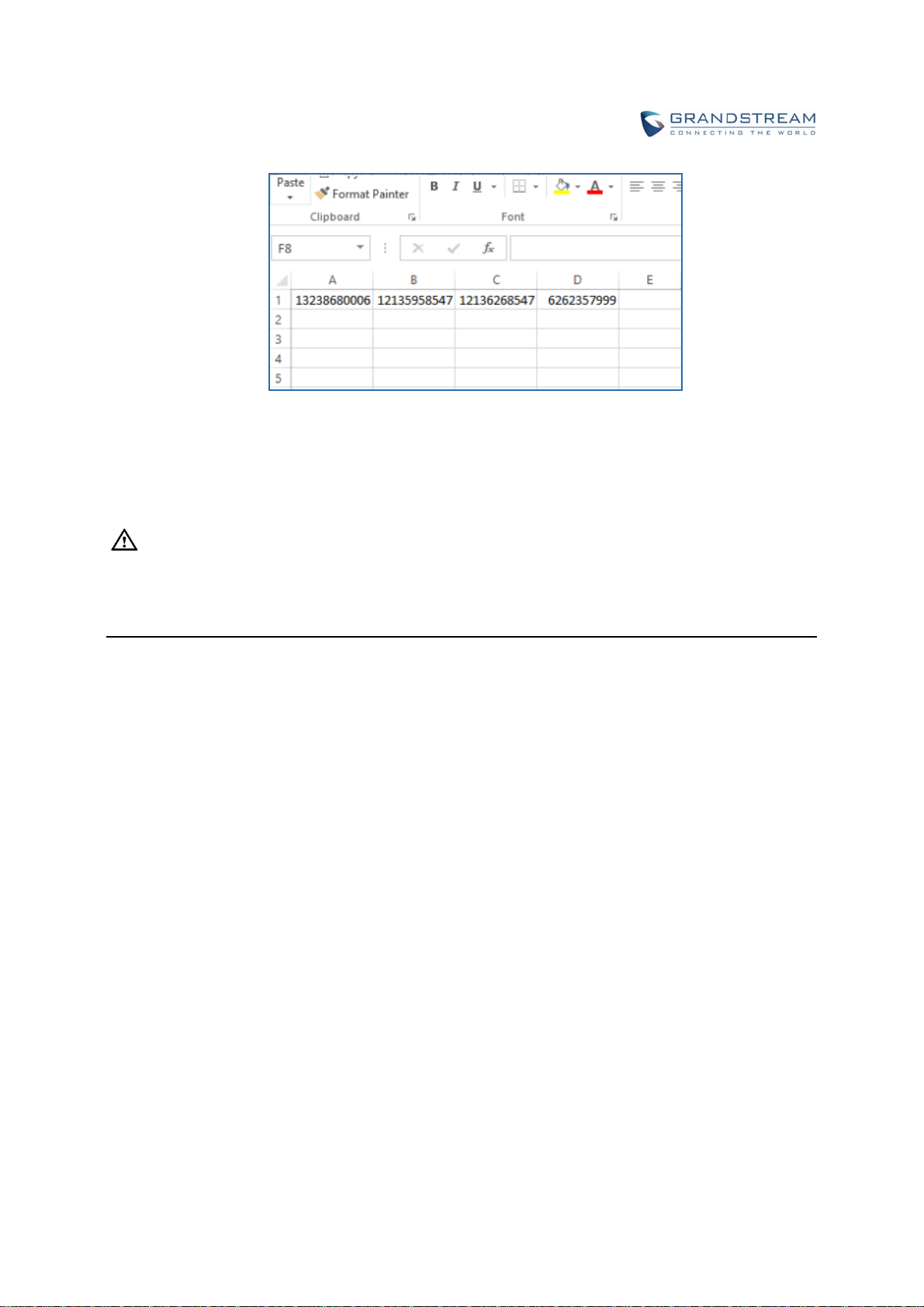
Figure 107: Blacklist csv File
--------------------------------------------------------------------------------------------------------------------------------------------
Note:
Users could also add a number to the Blacklist or remove a number from the Blacklist by dialing the feature
code for "Blacklist Add' (default: *40) and "Blacklist Remove" (default: *41) from an extension. The feature
code can be configured under Web GUI->PBX->Internal Options->Feature Codes.
Firmware Version 1.0.0.1 UCM6200 Series IP PBX User Manual Page 178 of 320
Page 10

Firmware Version 1.0.0.1 UCM6200 Series IP PBX User Manual Page 179 of 320
Page 11

CONFERENCEBRIDGE
The UCM6200 supports conference bridge allowing multiple bridges used at the same time:
UCM6202/6204 supports up to 3 conference bridges allowing up to 25 simultaneous PSTN or IP
participants.
UCM6208 supports up to 6 conference bridges allowing up to 32 simultaneous PSTN or IP participants.
The conference bridge configurations can be accessed under Web GUI->PBX->Call
Features->Conference. In this page, users could create, edit, view, invite, manage the participants and
delete conference bridges. The conference bridge status and conference call recordings (if recording is
enabled) will be displayed in this web page as well.
CONFERENCEBRIDGECONFIGURATIONS
Click on "Create New Conference Room" to add a new conference bridge.
Click on
Click on
Extension
Password
Admin Password
to edit the conference bridge.
to delete the conference bridge.
Table 58: Conference Bridge Configuration Parameters
Configure the conference number for the users to dial into the
conference.
When configured, the users who would like to join the conference call
must enter this password before accessing the conference bridge.
Note:
If "Public Mode" is enabled, the password is not required to join the
conference bridge thus this field is invalid.
The password has to be at least 4 characters.
Configure the password to join the conference bridge as administrator.
Conference administrator can manage the conference call via IVR (if
"Enable Caller Menu" is enabled) as well as invite other parties to join the
conference by dialing "0" (permission required from the invited party) or
"1" (permission not required from the invited party) during the conference
call.
Firmware Version 1.0.0.1 UCM6200 Series IP PBX User Manual Page 180 of 320
Page 12

Enable Caller Menu
Record Conference
Quiet Mode
Wait For Admin
Note:
If "Public Mode" is enabled, the password is not required to join the
conference bridge thus this field is invalid.
The password has to be at least 4 characters.
If enabled, conference participant could press the * key to access the
conference bridge menu. The default setting is "No".
If enabled, the calls in this conference bridge will be recorded
automatically in a .wav format file. All the recording files will be displayed
and can be downloaded in the conference web page. The default setting
is "No".
If enabled, if there are users joining or leaving the conference, voice
prompt or notification tone won't be played. The default setting is "No".
Note:
"Quiet Mode" and "Announce Callers" cannot be enabled at the same
time.
If enabled, the participants will not hear each other until the conference
administrator joins the conference. The default setting is "No".
Note:
If "Quiet Mode" is enabled, the voice prompt for "Wait For Admin" will not
be announced.
Enable User Invite
Announce Callers
Public Mode
Play Hold Music
If enabled, users could press 0 to invite other users (with the users'
permission) or press 1 to invite other users (without the user's permission)
to join the conference. The default setting is "No".
Note:
Conference administrator can always invite other users without enabling
this option.
If enabled, the caller will be announced to all conference participants
when there the caller joins the conference. The default setting is "No".
Note:
"Quiet Mode" and "Announce Callers" cannot be enabled at the same
time.
If enabled, no authentication will be required when joining the conference
call. The default setting is "Yes".
If enabled, the UCM6200 will play Hold music when there is only one user
in the conference. The default setting is "No".
Firmware Version 1.0.0.1 UCM6200 Series IP PBX User Manual Page 181 of 320
Page 13
Music On Hold
Select the music on hold class to be played in conference call. Music On
Hold class can be set up under web UI->PBX->Internal Options->Music
On Hold.
Skip Authentication When
Inviting User via Trunk from
Web GUI
If enabled, the invitation from Web GUI for a conference bridge with
password will skip the authentication for the invited users. The default
setting is "No".
JOINACONFERENCECALL
Users could dial the conference bridge extension to join the conference. If password is required, enter the
password to join the conference as a normal user, or enter the admin password to join the conference as
administrator.
INVITEOTHERPA RTIESTOJOINCONFERENCE
When using the UCM6200 conference bridge, there are two ways to invite other parties to join the
conference.
Invite from Web GUI.
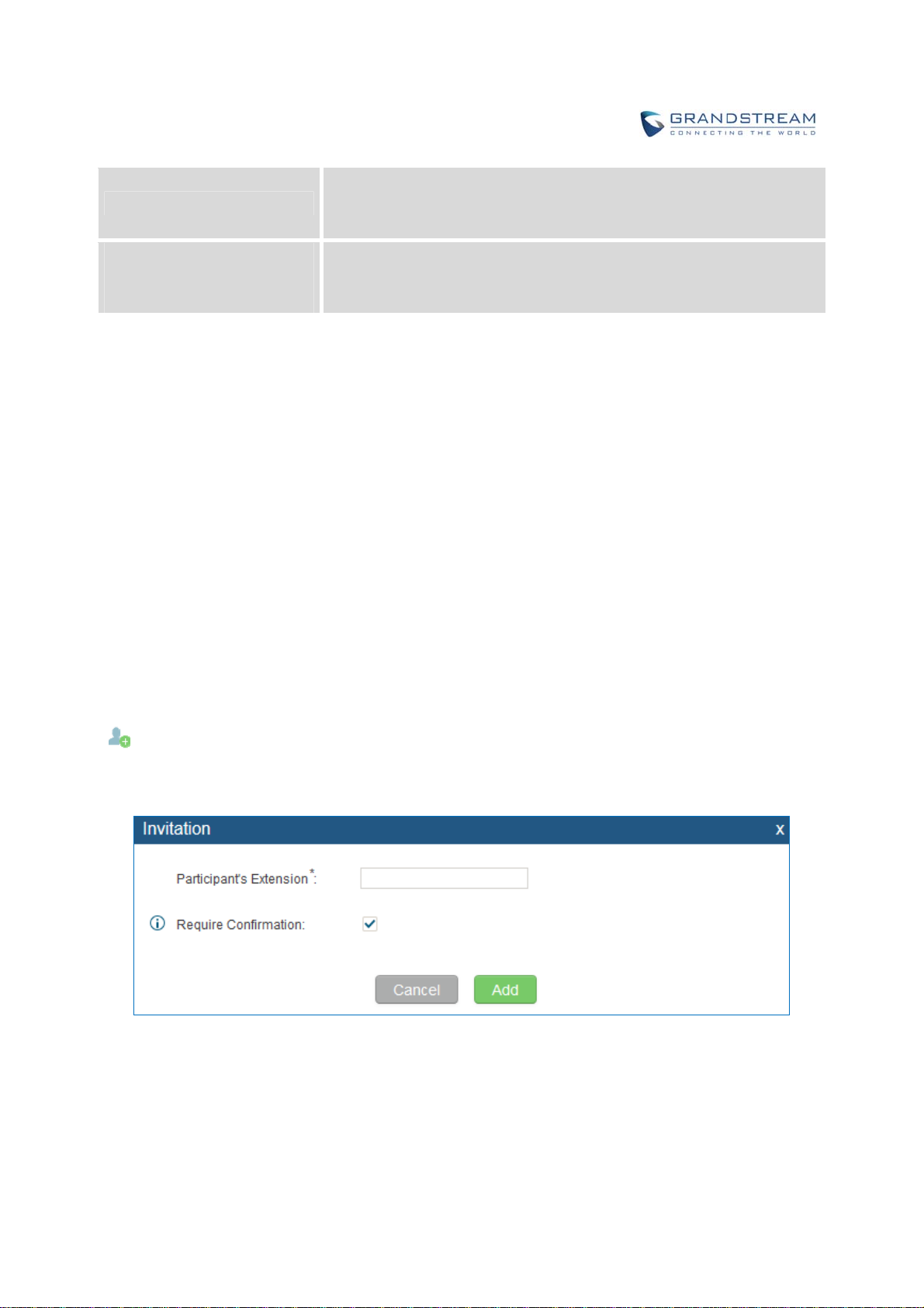
For each conference bridge in UCM6200 Web GUI->PBX->Call Features->Conference, there is an icon
for option "Invite a participant". Click on it and enter the number of the party you would like to invite.
Then click on "Add". A call will be sent to this number to join it into the conference.
Figure 108: Conference Invitation From Web GUI
Invite by dialing 0 or 1 during conference call.
Firmware Version 1.0.0.1 UCM6200 Series IP PBX User Manual Page 182 of 320
Page 14

A conference participant can invite other parties to the conference by dialing from the phone during the
conference call. Please make sure option "Enable User Invite" is turned on for the conference bridge first.
Enter 0 or 1 during the conference call. Follow the voice prompt to input the number of the party you would
like to invite. A call will be sent to this number to join it into the conference.
0: If 0 is entered to invite other party, once the invited party picks up the invitation call, a permission will be
asked to "accept" or "reject" the invitation before joining the conference.
1: If 1 is entered to invite other party, no permission will be required from the invited party.
--------------------------------------------------------------------------------------------------------------------------------------------
Note:
Conference administrator can always invite other parties from the phone during the call by entering 0 or 1.
To join a conference bridge as administrator, enter the admin password when joining the conference. A
conference bridge can have multiple administrators.
--------------------------------------------------------------------------------------------------------------------------------------------
DURINGTHECONFERENCE
During the conference call, users can manage the conference from web GUI or IVR.
Manage the conference call from Web GUI.
Log in UCM6200 web GUI during the conference call, the participants in each conference bridge will
be listed.
1. Click on
2. Click on
3. Click on
4. Click on
to kick a participant from the conference.
to mute the participant.
to lock this conference bridge so that other users cannot join it anymore.
to invite other users into the conference bridge.
Manage the conference call from IVR.
If "Enable Caller Menu" is enabled, conference participant can input * to enter the IVR menu for the
conference. Please see options listed in the table below.
Firmware Version 1.0.0.1 UCM6200 Series IP PBX User Manual Page 183 of 320
Page 15

Table 59: Conference Caller IVR Menu
Conference Administrator IVR Menu
1
2
3
4
5
6
7
8
1
4
5
6
Mute/unmute yourself.
Lock/unlock the conference bridge.
Kick the last joined user from the conference.
Decrease the volume of the conference call.
Decrease your volume.
Increase the volume of the conference call.
Increase your volume.
More options.
1: List all users currently in the conference call.
2: Kick all non-Administrator participants from the conference call.
3: Mute/Unmute all non-Administrator participants from the conference call.
4: Record the conference call.
8: Exit the caller menu and return to the conference.
Conference User IVR Menu
Mute/unmute yourself.
Decrease the volume of the conference call.
Decrease your volume.
Increase the volume of the conference call.
7
8
Increase your volume.
Exit the caller menu and return to the conference.
--------------------------------------------------------------------------------------------------------------------------------------------
Note:
When there is participant in the conference, the conference bridge configuration cannot be modified.
--------------------------------------------------------------------------------------------------------------------------------------------
RECORDCONFERENCE
The UCM6200 allows users to record the conference call and retrieve the recording from web
GUI->PBX->Call Features->Conference.
Firmware Version 1.0.0.1 UCM6200 Series IP PBX User Manual Page 184 of 320
Page 16
To record the conference call, when the conference bridge is in idle, enable "Record Conference" from the
conference bridge configuration dialog. Save the setting and apply the change. When the conference call
starts, the call will be automatically recorded in .wav format.
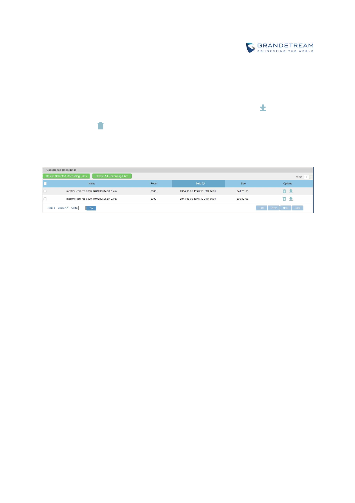
The recording files will be listed as below once available. Users could click on
recording or click on
to delete the recording. Users could also delete all recording files by clicking on
to download the
“Delate All Recording Files”, or delete multiple recording files at once by clicking on “Delete Selected
Recording Files” after selecting the recording files.
Figure 109: Conference Recording
Firmware Version 1.0.0.1 UCM6200 Series IP PBX User Manual Page 185 of 320
Page 17

CONFERENCESCHEDULE
CONFERENCESCHEUDLECONFIGURATION
Conference Schedule can be found under UCM6200 web UI->PBX->Call Features->Conference Schedule.
Users can create, edit, view and delete a Conference Schedule.
Click on “Create New Conference Schedule” to add a new Conference Schedule.
Click on the scheduled conference to edit or delete the event.
After the user configures UCM6200 with Google Service Settings [GOOGLE SERVICE SETTINGS SUPPORT]
and enables Google Calendar for Conference Schedule, the conference schedule on the UCM6200 can be
synchronized with Google Calendar for authorized Google account.
Table 60: Conference Schedule Parameters
Schedule Options
Conference Topic
Conference Room
Kick Time(m)
Description
Repeat
Schedule Time
Enable Google Calendar
Configure the name of the scheduled conference. Letters, digits, _ and are allowed.
Select a conference room for this scheduled conference.
Set kick time before conference starts. When kick time is reached, a
warning prompt will be played for all attendees in the conference room.
After 5 minutes, this conference room will be cleared and locked for the
scheduled conference to begin.
Note: Kick Time cannot be less than 6 minutes in order to clear the
conference room.
The description of scheduled conference.
Repeat interval of scheduled conference. By default it’s set to single
event.
Configure the beginning date and duration of scheduled conference.
Note: Please pay attention to avoid time conflict on schedules in the
same conference room.
Select this option to sync scheduled conference with Google Calendar.
Note: Google Service Setting OAuth2.0 must be configured on the
UCM6200. Please refer to section [GOOGLE SERVICE SETTINGS
SUPPORT].
Firmware Version 1.0.0.1 UCM6200 Series IP PBX User Manual Page 186 of 320
Page 18

Conference Administrator
Select the administrator of scheduled conference from selected
extensions.
Note:
“Public Mode” must be disabled from Conference Room Options tab.
Local Extension
Remote Extension
Special Extension
Remote Conference
Conference Room Options
Password
Admin Password
Enable Caller Menu
Record Conference
Select available extensions from the list to attend scheduled conference.
Select available extensions from the remote peer PBX.
Note: “LDAP Sync” must be enabled on the UCM6200 in order to view
remote extensions here.
Add extensions that are not in the list (both local and remote list). If the
user wishes to add the special extension, please match the pattern on the
outbound route.
Invite a remote conference.
Configure conference room password. Please note that if “Public Mode” is
enabled, this option is automatically disabled.
Configure the password to join as conference administrator. Please note
that if “Public Mode” is enabled, this option is automatically disabled.
If this option is enabled, conference participants will be able to access
conference bridge menu by pressing the * key.
If this option is enabled, conference call will be recorded in .wav format.
The recorded file can be found from Conference page.
If this option is enabled, the notification tone or voice prompt for joining or
leaving the conference won’t be played.
Quiet Mode
Note: Option “Quiet Mode” and option “Announce Caller” cannot be
enabled at the same time.
If this option is enabled, the participants in the conference won’t be able to
hear each other until conference administrator joins the conference.
Wait For Admin
Note: If “Quiet Mode” is enabled, voice prompt for this option won’t be
played.
If this option is enabled, the user can:
Press ‘0’ to invite others to join the conference with invited party’s
Enable User Invite
permission
Press ‘1’ to invite without invited party’s permission
Press ‘2’ to create a multi-conference bridge to another conference
room
Firmware Version 1.0.0.1 UCM6200 Series IP PBX User Manual Page 187 of 320
Page 19

Announce Callers
Public Mode
Play Hold Music
Press ‘3’ to drop all current multi-conference bridges
Note: Conference Administrator is always allowed to access this menu.
If this option is enabled, when a participant joins the conference room,
participant’s name will be announced to all members in the conference
room.
Note: Option “Quiet Mode” and option “Announce Caller” cannot be
enabled at the same time.
If this option is enabled, no authentication is required for entering the
conference room.
Note: Please be aware of the potential security risks when turning on this
option.
If this option is enabled, UCM6200 will play Hold Music while there is only
one participant in the conference room or the conference is not yet
started.
If this option is enabled, the invitation from Web GUI via a trunk with
Skip Authentication When
Inviting Users via Trunk from
Web GUI
password won’t require authentication.
Note: Please be aware of the potential security risks when turning on this
option.
Cleaner Options
Cleaner Options
Enable Conference
Schedules Cleaner
Conference Schedules Clean
Time
Clean Interval
If this option is enabled, conference schedules will be automatically
cleaned as configured.
Enter the clean time (in hours). The valid range is from 0 to 23.
Enter the clean interval (in days). The valid range is from 1 to 30.
Show/hide Conference Schedule Table
Enable this option will allow web UI to display scheduled conference in Conference Schedule Table. Please
see figure below.
Firmware Version 1.0.0.1 UCM6200 Series IP PBX User Manual Page 188 of 320
Page 20
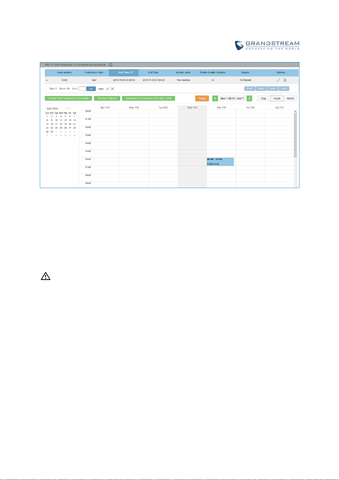
Figure 110: Conference Schedule
Once the conference room is scheduled, at the kick time, all users will be removed from conference room
and no extension is allowed to join the conference room anymore. At the scheduled conference time,
UCM6200 will send INVITE to the extensions that have been selected for conference.
--------------------------------------------------------------------------------------------------------------------------------------------
Note:
Please make sure that outbound route is properly configured for remote extensions to join the
conference.
Once Kick Time is reached, Conference Schedule is locked and cannot be modified.
--------------------------------------------------------------------------------------------------------------------------------------------
Firmware Version 1.0.0.1 UCM6200 Series IP PBX User Manual Page 189 of 320
Page 21

IVR
CONFIGUREIVR
IVR configurations can be accessed under the UCM6200 Web GUI->PBX->Call Features->IVR. Users
could create, edit, view and delete an IVR.
Click on "Create New IVR" to add a new IVR.
Click on
Click on
Basic Settings
Name
Extension
DID Destination
to edit the IVR configuration.
to delete the IVR.
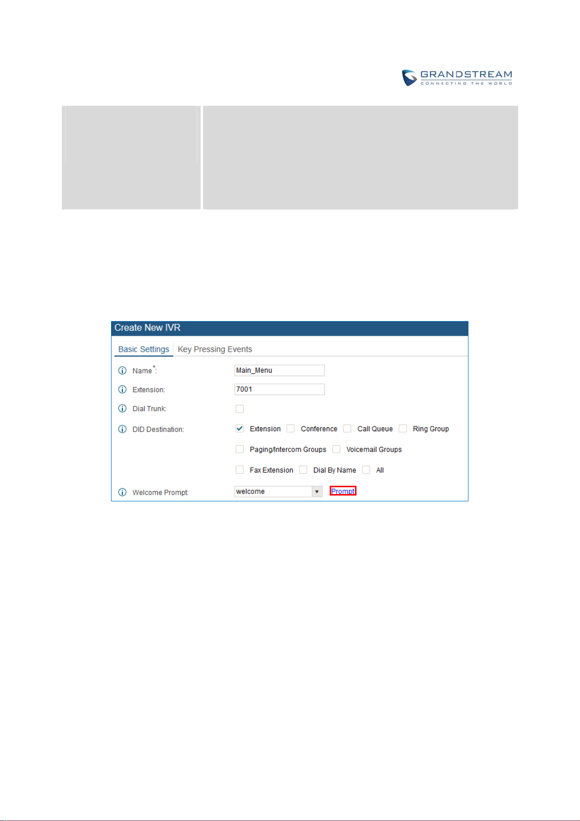
Table 61: IVR Configuration Parameters
Configure the name of the IVR. Letters, digits, _ and - are allowed.
Enter the extension number for users to access the IVR.
This option shows up only when "By DID" is selected. This controls the
destination that can be reached by the external caller via the inbound
route. The DID destination are:
Extension
Conference
Call Queue
Ring Group
Paging/Intercom Groups
Voicemail Groups
Fax Extension
Dial By Name
All
If enabled, all callers to the IVR is allowed to use trunk. The permission
Dial Trunk
Permission
Firmware Version 1.0.0.1 UCM6200 Series IP PBX User Manual Page 190 of 320
must be configured for the users to use the trunk first. The default setting
is "No".
Assign permission level for outbound calls if "Dial Trunk" is enabled. The
available permissions are "Internal", "Local", "National" and
"International" from the lowest level to the highest level. The default
setting is "Internal". If the user tries to dial outbound calls after dialing into
the IVR, the UCM6200 will compared the IVR's permission level with the
outbound route's privilege level. If the IVR's permission level is higher
than (or equal to) the outbound route's privilege level, the call will be
Page 22

Welcome Prompt
Digit Timeout
Response Timeout
allowed to go through.
Select an audio file to play as the welcome prompt for the IVR. Click on
"Prompt" to add additional audio file under web GUI->Internal
Options->IVR Prompt.
Configure the timeout between digit entries. After the user enters a digit,
the user needs to enter the next digit within the timeout. If no digit is
detected within the timeout, the UCM6200 will consider the entries
complete. The default timeout is 3 seconds.
After playing the prompts in the IVR, the UCM6200 will wait for the DTMF
entry within the timeout (in seconds). If no DTMF entry is detected within
the timeout, a timeout prompt will be played. The default setting is 10
seconds.
Response Timeout Prompt
Invalid Prompt
Response Timeout Repeat
Loops
Invalid Repeat Loops
Language
Key Pressing Events
Key Press Event:
Press 0
Press 1
Press 2
Press 3
Press 4
Press 5
Press 6
Press 7
Press 8
Select the prompt message to be played when timeout occurs.
Select the prompt message to be played when an invalid extension is
pressed.
Configure the number of times to repeat the prompt if no DTMF input is
detected. When the loop ends, it will go to the timeout destination if
configured, or hang up. The default setting is 3.
Configure the number of times to repeat the prompt if the DTMF input is
invalid. When the loop ends, it will go to the invalid destination if
configured, or hang up. The default setting is 3.
Select the voice prompt language to be used for this IVR. The default
setting is "Default" which is the selected voice prompt language under
web GUI->PBX->Internal Options->Language. The dropdown list
shows all the current available voice prompt languages on the UCM6200.
To add more languages in the list, please download voice prompt
package by selecting "Check Prompt List" under web
GUI->PBX->Internal Options->Language.
Select the event for each key pressing for 0-9, *, Timeout and Invalid. The
event options are:
Extension
Voicemail
Conference Rooms
Voicemail Group
IVR
Ring Group
Queues
Page Group
Firmware Version 1.0.0.1 UCM6200 Series IP PBX User Manual Page 191 of 320
Page 23
Press 9
Press *
Timeout
Invalid
Fax
Custom Prompt
Hangup
DISA
Dial By Name
External Number
Callback
CREATECUSTOMPROMPT
To record new IVR prompt or upload IVR prompt to be used in IVR, click on “Prompt” next to the “Welcome
Prompt” option and the users will be redirected to Custom Prompt page. Or users could go to Web
GUI->PBX->Internal Options->Custom Prompt page directly.
Figure 111: Click on Prompt to Create IVR Prompt
Once the IVR prompt file is successfully added to the UCM6200, it will be added into the prompt list
options for users to select in different IVR scenarios.
RECORDNEWCUSTOMPROMPT
Settings
In the UCM6200 web UI->PBX->Internal Options->Custom Prompt page, click on “Record New Custom
Prompt” and follow the steps below to record new IVR prompt.
Firmware Version 1.0.0.1 UCM6200 Series IP PBX User Manual Page 192 of 320
Page 24
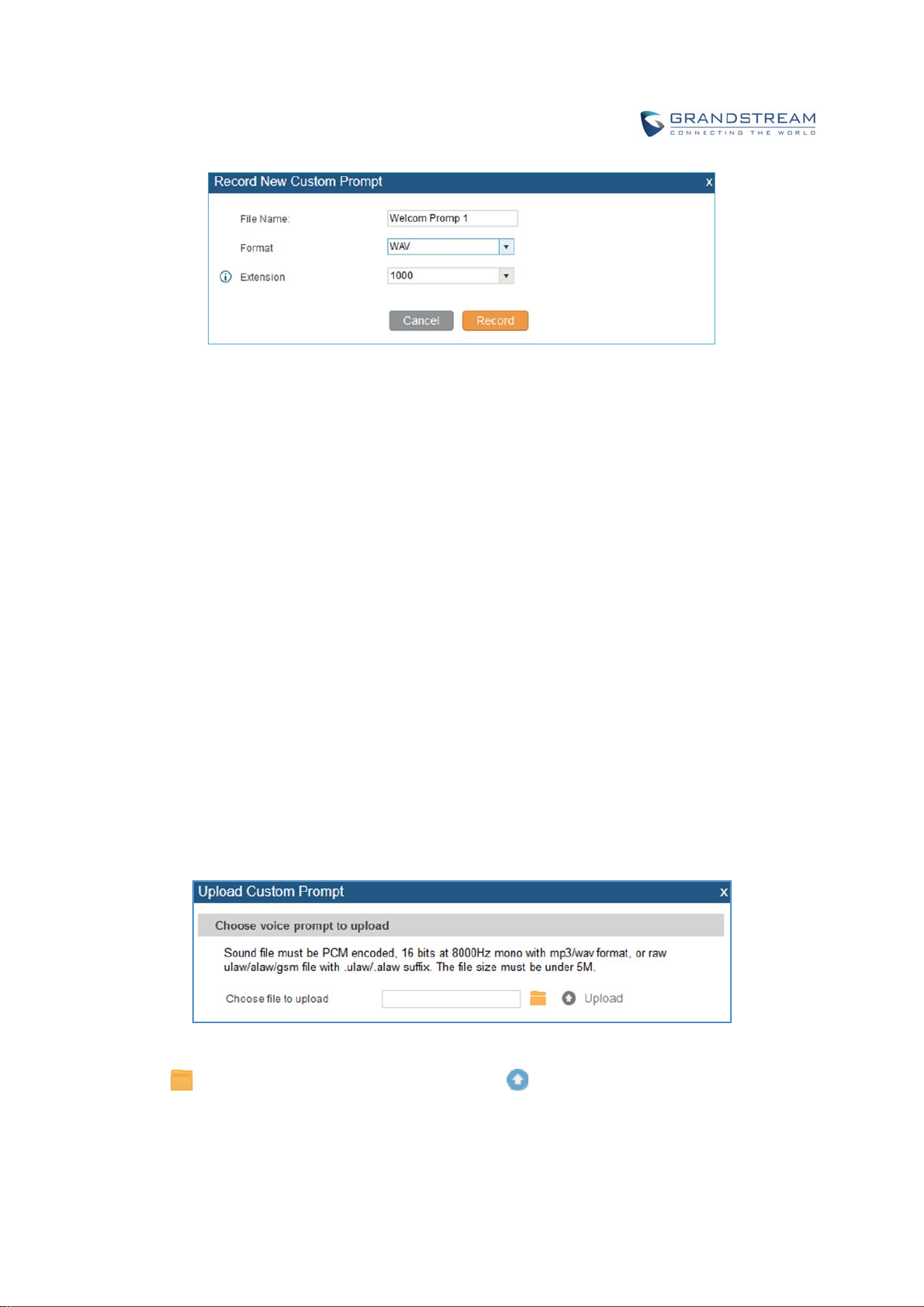
Figure 112: Record New Custom Prompt
Specify the IVR file name.
Select the format (GSM or WAV) for the IVR prompt file to be recorded.
Select the extension to receive the call from the UCM6200 to record the IVR prompt.
Click the “Record” button. A request will be sent to the UCM6200. The UCM6200 will then call the
extension for recording the IVR prompt from the phone.
Pick up the call from the extension and start the recording following the voice prompt.
The recorded file will be listed in the IVR Prompt web page. Users could select to re-record, play or
delete the recording.
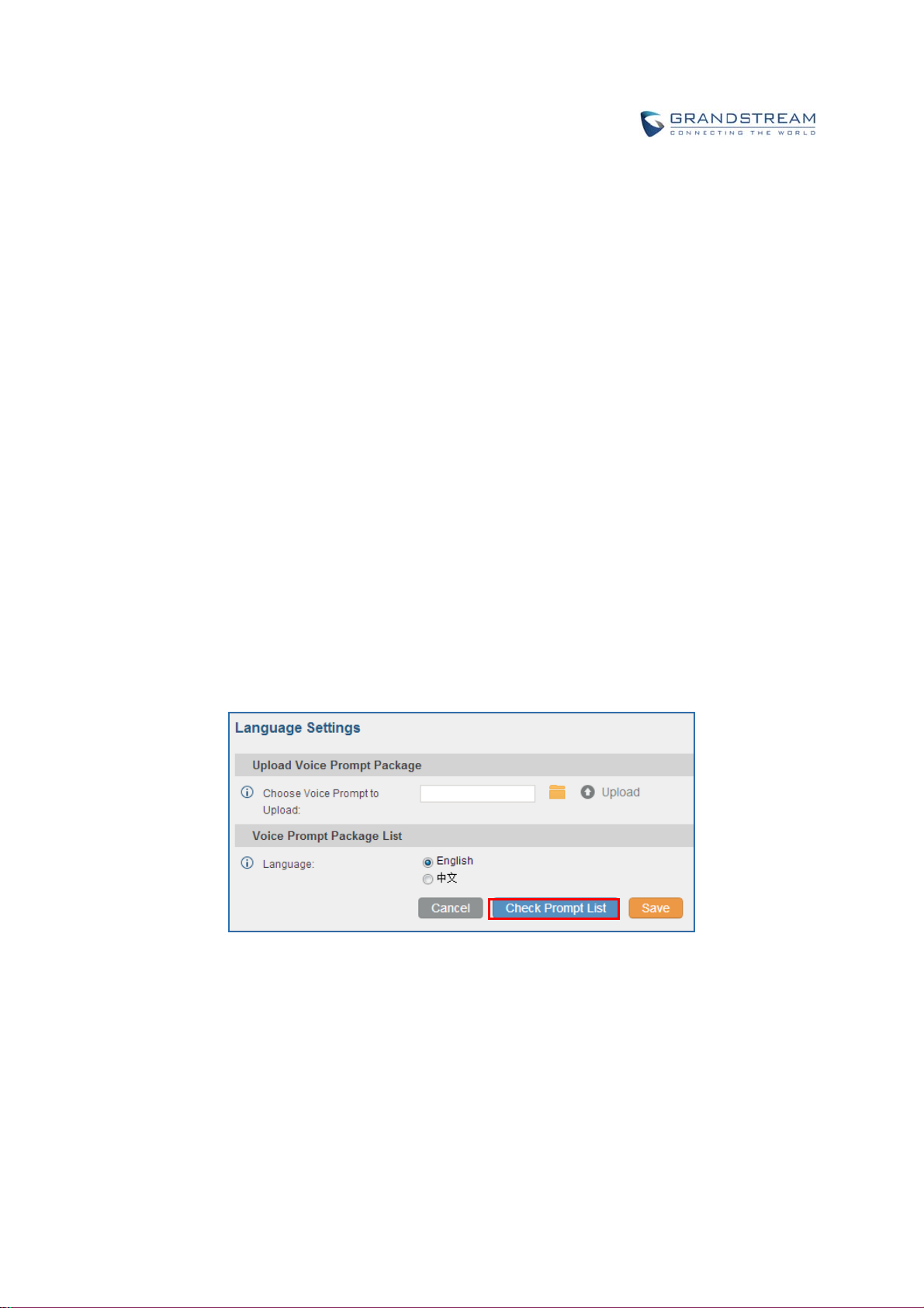
UPLOADCUSTOMPROMPT
If the user has a pre-recorded IVR prompt file, click on “Upload Custom Prompt” in Web
GUI->PBX->Internal Options->Custom Prompt page to upload the file to the UCM6200. The following
are required for the IVR prompt file to be successfully uploaded and used by the UCM6200:
PCM encoded.
16 bits.
8000Hz mono.
In .mp3 or .wav format; or raw/ulaw/alaw/gsm file with .ulaw or .alaw suffix.
File size under 5M.
Figure 113: Upload Custom Prompt
Click on to select audio file from local PC and click on to start uploading. Once uploaded, the file
will appear in the Custom Prompt web page.
Firmware Version 1.0.0.1 UCM6200 Series IP PBX User Manual Page 193 of 320
Page 25
LANGUAGESETTINGSFORVOICEPROMPT
The UCM6200 supports multiple languages in web GUI as well as system voice prompt. Currently, there
are 16 languages supported in system voice prompt: English (United States), Arabic, Chinese, Dutch,
English (United Kingdom), French, German, Greek, Hebrew, Italian, Polish, Portuguese, Russian,
Spanish, Swedish and Turkish.
English (United States) and Chinese voice prompts are built in with the UCM6200 already. The other
languages provided by Grandstream can be downloaded and installed from the UCM6200 web GUI
directly. Additionally, users could customize their own voice prompts, package them and upload to the
UCM6200.
Language settings for voice prompt can be accessed under Web GUI->PBX->Internal
Options->Language.
DOWNLOADANDINSTALLVOICEPROMPTPACK AGE
To download and install voice prompt package in different languages from UCM6200 web GUI, click on
"Check Prompt List" button.
Figure 114: Language Settings for Voice Prompt
A new dialog window of voice prompt package list will be displayed. Users can see the version number
(latest version available V.S. current installed version), package size and options to upgrade or download
the language.
Firmware Version 1.0.0.1 UCM6200 Series IP PBX User Manual Page 194 of 320
Page 26
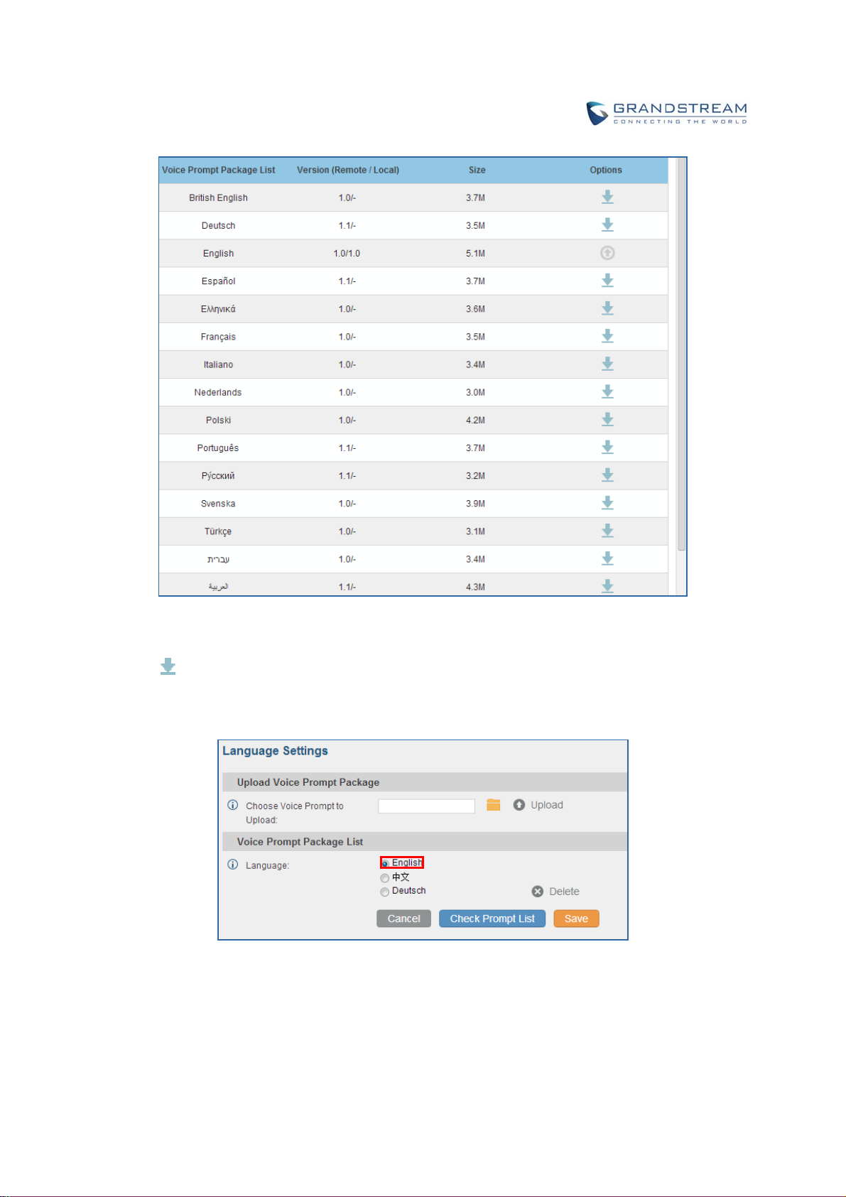
Figure 115: Voice Prompt Package List
Click on
to download the language to the UCM6200. The installation will be automatically started
once the downloading is finished.
Figure 116: New Voice Prompt Language Added
A new language option will be displayed after successfully installed. Users then could select it to apply in
the UCM6200 system voice prompt or delete it from the UCM6200.
Firmware Version 1.0.0.1 UCM6200 Series IP PBX User Manual Page 195 of 320
Page 27
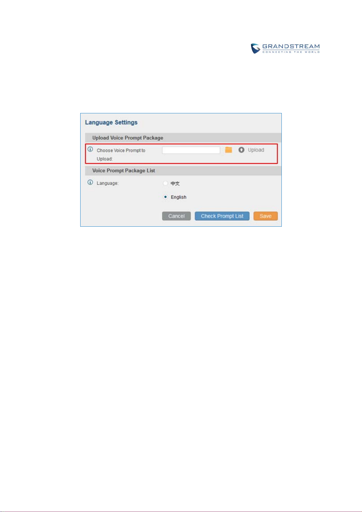
CUSTOMIZESPECIFICPROMPT
On the UCM6200, if the user needs to replace some specific customized prompt, the user can upload a single
specific customized prompt from web UI->PBX->Internal Options->Language instead of the entire language
pack.
Figure 117: Upload Single Voice Prompt for Entire Language Pack
Firmware Version 1.0.0.1 UCM6200 Series IP PBX User Manual Page 196 of 320
Page 28

Firmware Version 1.0.0.1 UCM6200 Series IP PBX User Manual Page 197 of 320
Page 29

VOICEMAIL
CONFIGUREVOICEMAIL
If the voicemail is enabled for UCM6200 extensions, the configurations of the voicemail can be globally set
up and managed under Web GUI->PBX->Call Features->Voicemail.
Table 62: Voicemail Settings
Max Greeting
Dial ‘0’ For Operator
Max Messages Per Folder
Max Message Time
Min Effective Message Time
Configure the maximum number of seconds for the voicemail greeting.
The default setting is 60 seconds.
If enabled, the caller can press 0 to exit the voicemail application and
connect to the configured operator’s extension. The operator extension
can be configured under web GUI->PBX->Internal Options->General.
Configure the maximum number of messages per folder in users’
voicemail. The valid range 10 to 1000. The default setting is 50.
Select the maximum duration of the voicemail message. The message
will not be recorded if the duration exceeds the max message time. The
default setting is 15 minutes. The available options are:
1 minute
2 minutes
5 minutes
15 minutes
30 minutes
Unlimited
Configure the minimum duration (in seconds) of a voicemail message.
Messages will be automatically deleted if the duration is shorter than the
Min Message Time. The default setting is 3 seconds. The available
options are:
No minimum
1 second
2 seconds
3 seconds
4 seconds
5 seconds
Note:
Silence and noise duration are not counted in message time.
Announce Message Caller-ID
Firmware Version 1.0.0.1 UCM6200 Series IP PBX User Manual Page 198 of 320
If enabled, the caller ID of the user who has left the message will be
announced at the beginning of the voicemail message. The default setting
Page 30

is "No".
Announce Message Duration
If enabled, the message duration will be announced at the beginning of
the voicemail message. The default setting is "No".
If enabled, a brief introduction (received time, received from, and etc) of
Play Envelope
each message will be played when accessed from the voicemail
application. The default setting is "Yes".
Play from Last
Allow User Review
If enabled, UCM will play from the voice message left most recently; if
disabled, UCM will play from the earliest left voice message
If enabled, users can review the message following the IVR before
sending the message out. The default setting is "No".
ACCESSVOICEMAIL
If the voicemail is enabled for UCM6200 extensions, the users can dial the voicemail access feature code
(by default *98 or *97) to access the extension’s voicemail. The users will be prompt to enter the voicemail
password and then can enter digits from the phone keypad to navigate in the IVR menu for different
options.
Table 63: Voicemail IVR Menu
Main Menu Sub Menu 1 Sub Menu 2
1 - New
messages
2 - Change
folders
3 - Advanced options
5 - Repeat the current message
7 - Delete this message
8 - Forward the message to another user
9 – Save
* - Help
# - Exit
0 - New messages
1 - Old messages
2 - Work messages
3 - Family messages
4 - Friend messages
# - Cancel
1 - Send a reply
2 - Call the person who sent this message
3 - Hear the message envelop
4 - Leave a message
* - Return to the main menu
Firmware Version 1.0.0.1 UCM6200 Series IP PBX User Manual Page 199 of 320
Page 31

1 - Send a reply
3 Advanced
options
0 - Mailbox
options
2 - Call the person who sent this message
3 - Hear the message envelop
4 - Leave a message
* - Return to the main menu
1 - Record your unavailable message
2 - Record your busy message
3 - Record your name
4 - Record temporary greeting
5 - Change your password
1 - Accept this recording
2 - Listen to it
3 - Re-record your message
1 - Accept this recording
2 - Listen to it
3 - Re-record your message
1 - Accept this recording
2 - Listen to it
3 - Re-record your message
1 - Accept this recording
2 - Listen to it
3 - Re-record your message
* - Return to the main menu
VOICEMAILEMAILSETTINGS
The UCM6200 can be configured to send the voicemail as attachment to Email. Click on "Voicemail Email
Settings" button to configure the Email attributes and content.
Table 64: Voicemail Email Settings
Attach Recordings to E-Mail
Keep Recordings
Template For Voicemail Emails
If enabled, voicemails will be sent to user's Email address. The default
setting is "Yes".
If enabled, voicemail will be stored in the UCM6200 after the email is sent.
The default setting is “Yes”.
Fill in the "Subject:" and "Message:" content, to be used in the Email
when sending to the user.
The template variables are:
\t: TAB
${VM_NAME}: Recipient's first name and last name
Firmware Version 1.0.0.1 UCM6200 Series IP PBX User Manual Page 200 of 320
Page 32

${VM_DUR}: The duration of the voicemail message
${VM_MAILBOX}: The recipient's extension
${VM_CALLERID}: The caller ID of the person who has left the
message
${VM_MSGNUM}: The number of messages in the mailbox
${VM_DATE}: The date and time when the message is left
Figure 118: Voicemail Email Settings
Click on "Load Default Settings" button to view the default template as an example.
CONFIGUREVOICEMAILGROUP
The UCM6200 supports voicemail group and all the extensions added in the group will receive the
voicemail to the group extension. The voicemail group can be configured under Web GUI->PBX->Call
Features->V oicemail Group. Click on "Create New Voicemail Group" to configure the group.
Firmware Version 1.0.0.1 UCM6200 Series IP PBX User Manual Page 201 of 320
Page 33

Figure 119: Voicemail Group
Table 65: Voicemail Group Settings
Extension
Name
Voicemail Password
Enter the Voicemail Group Extension. The voicemail messages left to this
extension will be forwarded to all the voicemail group members.
Configure the Name to identify the voicemail group. Letters, digits, _ and are allowed.
Configure the voicemail password for the users to check voicemail
messages.
Email Address Configure the Email address for the voicemail group extension.
Select available mailboxes from the left list and add them to the right list.
Voicemail Group Mailboxes
The extensions need to have voicemail enabled to be listed in available
mailboxes list.
Firmware Version 1.0.0.1 UCM6200 Series IP PBX User Manual Page 202 of 320
Page 34

Firmware Version 1.0.0.1 UCM6200 Series IP PBX User Manual Page 203 of 320
Page 35

RINGGROUP
The UCM6200 supports ring group feature with different ring strategies applied to the ring group members.
This section describes the ring group configuration on the UCM6200.
CONFIGURERINGGROUP
Ring group settings can be accessed via Web GUI->PBX->Call Features->Ring Group.
Figure 120: Ring Group
Click on “Create New Ring Group” to add ring group.
Click on
Click on
Ring Group Name
Extension Configure the ring group extension.
Ring Group Members
Selected LDAP Numbers
Ring Strategy
to edit the ring group. The following table shows the ring group configuration parameters.
to delete the ring group.
Table 66: Ring Grou p Para meters
Configure ring group name to identify the ring group. Letters, digits, _ and
– are allowed.
Select available users from the left side to the ring group member list on
the right side. Click on to arrange the order.
Select available remote users from the left side to the ring group member
list on the right side. Click on to arrange the order. Note:
LDAP Sync must be enabled first.
Select the ring strategy. The default setting is “Ring in order”.
Ring simultaneously.
Ring all the members at the same time when there is incoming call to
the ring group extension. If any of the member answers the call, it will
stop ringing.
Ring in order.
Ring the members with the order configured in ring group list. If the
first member doesn’t answer the call, it will stop ringing the first
member and start ringing the second member.
Firmware Version 1.0.0.1 UCM6200 Series IP PBX User Manual Page 204 of 320
Page 36

Custom Prompt
Ring Timeout on Each Member
Auto Record
Enable Destination
Secret
This option is to set a custom prompt for a ring group to announce to
caller. Click on ‘Prompt’, it will direct to the page PBX->Internal
Options->Custom Prompt, where users could record new prompt or
upload prompt files.
Configure the number of seconds to ring each member. If set to 0, it will
keep ringing. The default setting is 30 seconds.
Note:
The actual ring timeout might be overridden by users if the phone has ring
timeout settings as well.
If enabled, calls on this ring group will be automatically recorded. The
default setting is No. The recording files can be accessed from web
GUI->CDR->Recording Files .
If enabled, users could select extension, voicemail, ring group, IVR, call
queue, voicemail group as the destination if the call to the ring group has
no answer. Secret and Email address are required if voicemail is selected
as the destination.
Configure the password to access the ring group extension's voicemail.
Note:
The password has to be at least 4 characters.
Email Address
Configure the Email address of the ring group extension's voicemail. If
"Attach Recordings to E-mail" is enabled from Web
GUI->PBX->Voicemail->Voicemail Email Settings, the voicemail can
be sent to the ring group's Email address as attachment.
Firmware Version 1.0.0.1 UCM6200 Series IP PBX User Manual Page 205 of 320
Page 37

Figure 121: Ring Group Configuration
REMOTEEXTENSIONINRINGGROUP
Remote extensions from the peer trunk of a remote UCM6200 can be included in the ring group with local
extension. An example of Ring Group with peer extensions is presented in the following:
1. Creating SIP Peer Trunk between both UCM6200_A and UCM6200_B. SIP Trunk can be found under
web UI-> PBX-> Basic/Call Routes-> VoIP Trunks. Also, please configure their Inbound/Outbound
routes accordingly.
2. Click edit button in the menu
option will allow UCM6200_A update remote LDAP server automatically from peer UCM6200_B. In
addition, Sync LDAP Password must match for UCM6200_A and UCM6200_B in order to sync LDAP
contact automatically. Port number can be anything between 0~65535, and use the outbound rule
created in step 1 for the LDAP Outbound Rule option.
, and check if Sync LDAP Enable is selected, this
Firmware Version 1.0.0.1 UCM6200 Series IP PBX User Manual Page 206 of 320
Page 38

Figure 122: Sync LDAP Server option
3. In case if LDAP server doesn’t sync automatically, user can manually sync LDAP server. Under VoIP
Trunks page, click sync button shown in the following figure to manually sync LDAP contacts from
peer UCM6200.
Figure 123: Manually Sync LDAP Server
Firmware Version 1.0.0.1 UCM6200 Series IP PBX User Manual Page 207 of 320
Page 39

4. Under Ring Groups setting page, click . Ring Groups can be found
under web UI-> PBX-> Call Features-> Ring Groups.
5. If LDAP server is synced correctly, Available LDAP Numbers box will display available remote
extensions that can be included in the current ring group. Please also make sure the extensions in the
peer UCM6200 can be included into that UCM6200’s LDAP contact.
Figure 124: Ring Group Remote Extension
Firmware Version 1.0.0.1 UCM6200 Series IP PBX User Manual Page 208 of 320
Page 40

Firmware Version 1.0.0.1 UCM6200 Series IP PBX User Manual Page 209 of 320
Page 41

PAG I NGANDINTERCOMGROUP
Paging and Intercom Group can be used to make an announcement over the speaker on a group of
phones. Targeted phones will answer immediately using speaker. The UCM6200 paging and intercom can
be used via feature code to a single extension or a paging/intercom group. This sections describes the
configuration of paging/intercom group under Web GUI->PBX->Call Features->Paging/Intercom.
CONFIGUREPAGI NG/ IN T ERC OMGROUP
Click on "Create New Paging/Intercom Group" to add paging/intercom group.
Figure 125: Paging/Intercom Group
Table 67: Paging/Intercom Group Configuration Parameters
Name Configure paging/intercom group name.
Extension Configure the paging/intercom group extension.
Type Select "2-way Intercom" or "1-way Page".
This option is to set a custom prompt for a paging/intercom group to
Custom Prompt
announce to caller. Click on ‘Prompt’, it will direct to the page
PBX->Internal Options->Custom Prompt, where users could record
new prompt or upload prompt files.
Page/Intercom Group
Members
Firmware Version 1.0.0.1 UCM6200 Series IP PBX User Manual Page 210 of 320
Select available users from the left side to the paging/intercom group
member list on the right.
Page 42

Click on to edit the paging/intercom group.
Click on
to delete the paging/intercom group.
Click on "Paging/Intercom Group Settings" to edit Alert-Info Header. This header will be included in the
SIP INVITE message sent to the callee in paging/intercom call.
Figure 126: Page/Intercom Group Settings
The UCM6200 has pre-configured paging/intercom feature code. By default, the Paging Prefix is *81
and the Intercom Prefix is *80. To edit page/intercom feature code, click on "Feature Codes" in the
"Paging/Intercom Group Settings" dialog. Or users could go to Web GUI->PBX->Internal
Options->Feature Codes directly.
Firmware Version 1.0.0.1 UCM6200 Series IP PBX User Manual Page 211 of 320
Page 43

CALLQUEUE
The UCM6200 supports call queue by using static agents or dynamic agents. Call Queue system can
accept more calls than the available agents. Incoming calls will be held until next representative is
available in the system. This section describes the configuration of call queue under Web GUI->PBX->Call
Features->Call Queue.
CONFIGURECALLQUEUE
Call queue settings can be accessed via Web GUI->PBX->Call Features->Call Queue.
Figure 127: Call Queue
Click on "Create New Queue" to add call queue.
Click on
below.
Extension Configure the call queue extension.
Name Configure the call queue name to identify the call queue.
Strategy
Firmware Version 1.0.0.1 UCM6200 Series IP PBX User Manual Page 212 of 320
to edit the call queue. The call queue configuration parameters are listed in the table
Table 68: Call Queue Configuration Parameters
Select the strategy for the call queue.
Ring All
Ring all available Agents simultaneously until one answers.
Linear
Ring agents in the specified order.
Page 44

Music On Hold
Leave When Empty
Least Recent
Ring the agent who has been called the least recently.
Fewest Calls
Ring the agent with the fewest completed calls.
Random
Ring a random agent.
Round Robin
Ring the agents in Round Robin scheduling with memory.
The default setting is "Ring All".
Select the Music On Hold class for the call queue.
Note:
Music On Hold classes can be managed from Web GUI-> PBX->Internal
Options->Music On Hold.
Configure whether the callers will be disconnected from the queue or not
if the queue has no agent anymore. The default setting is "Strict".
Yes
Callers will be disconnected from the queue if all agents are paused
or invalid.
No
Never disconnect the callers from the queue when the queue is
empty.
Strict
Callers will be disconnected from the queue if all agents are paused,
invalid or unavailable.
Configure whether the callers can dial into a call queue if the queue has
no agent. The default setting is "No".
Yes
Callers can always dial into a call queue.
Dial in Empty Queue
No
Callers cannot dial into a queue if all agents are paused or invalid.
Strict
Callers cannot dial into a queue if the agents are paused, invalid or
unavailable.
Dynamic Login Password
Ring Time Out
If enabled, the configured PIN number is required for dynamic agent to
log in. The default setting is disabled.
Configure the number of seconds an agent will ring before the call goes to
the next agent. The default setting is 15 seconds.
Wrapup Time Configure the number of seconds before a new call can ring the queue
Firmware Version 1.0.0.1 UCM6200 Series IP PBX User Manual Page 213 of 320
Page 45

Max Queue Length
Report Hold Time
Wait Time
after the last call on the agent is completed. If set to 0, there will be no
delay between calls to the queue. The default setting is 15 seconds.
Configure the maximum number of calls to be queued at once. This
number does not include calls that have been connected with agents. It
only includes calls not connected yet. The default setting is 0, which
means unlimited. When the maximum value is reached, the caller will be
treated with busy tone followed by the next calling rule after attempting to
enter the queue.
If enabled, the UCM6200 will report (to the agent) the duration of time of
the call before the caller is connected to the agent. The default setting is
"No".
If enabled, users will be disconnected after the configured number of
seconds. The default setting is "No".
Note:
It is recommended to configure "Wait Time" longer than the "Wrapup
Time".
Auto Record
Enable Destination
Queue Timeout
Failover Destination
Enable Feature Codes
Agents
Click on
to delete the call queue.
If enabled, the calls on the call queue will be automatically recorded. The
recording files can be accessed in Queue Recordings under web
GUI->PBX->Call Features->Call Queue.
If enabled, the incoming call for the call queue will be routed to the
destination configured in the next field if none of the agents answers the
call after ringing for a time of “Ring Timeout”.
Configure the global timeout (in seconds) of call queue. It must be bigger
than the value of ring timeout. The call in the queue will be transferred to
the failover destination directly if this time is exceeded.
Configure the call destination for the call to be routed to if no agent in this
call queue answers the call.
Enable feature codes option for call queue. For example, *83 is used for
“Agent Pause”
Select the available users to be the static agents in the call queue.
Choose from the available users on the left to the static agents list on the
right. Click on to arrange the order.
Click on "Agent Login Settings" to configure Agent Login Extension Postfix and Agent Logout
Extension Postfix. Once configured, users could log in the call queue as dynamic agent.
Firmware Version 1.0.0.1 UCM6200 Series IP PBX User Manual Page 214 of 320
Page 46

Figure 128: Agent Login Settings
For example, if the call queue extension is 6500, Agent Login Extension Postfix is * and Agent Logout
Extension Postfix is **, users could dial 6500* to login to the call queue as dynamic agent and dial
6500** to logout from the call queue. Dynamic agent doesn't need to be listed as static agent and can
log in/log out at any time.
Call queue feature code "Agent Pause" and "Agent Unpause" can be configured under Web
GUI->PBX->Internal Options->Feature Codes. The default feature code is *83 for "Agent Pause"
and *84 for "Agent Unpause".
Queue recordings are shown on the Call Queue page. Click on
in .wav format; click on
to delete the recording file. To delete multiple recording files by one click,
to download the recording file
select several recording files to be deleted and click on “Delete Selected Recording Files” or click on
“Delete All Recording Files” to delete all recording files.
Firmware Version 1.0.0.1 UCM6200 Series IP PBX User Manual Page 215 of 320
Page 47

EXTENSIONGROUPS
The UCM6200 extension group feature allows users to assign and categorize extensions in different
groups to better manage the configurations on the UCM6200. For example, when configuring "Enable
Filter on Source Caller ID", users could select a group instead of each person's extension to assign. This
feature simplifies the configuration process and helps manage and categorize the extensions for business
environment.
CONFIGUREEXTENSIONGROUPS
Extension group can be configured via Web GUI->PBX->Call Features->Extension Groups.
Click on "Create New Extension Group" to create a new extension group.
Click on
Select extensions from the list on the left side to the right side.
Click on
to edit the extension group.
Figure 129: Edit Extension Group
to delete the extension group.
Firmware Version 1.0.0.1 UCM6200 Series IP PBX User Manual Page 216 of 320
Page 48

USINGEXTENSIONGROUPS
Here is an example where the extension group can be used. Go to Web GUI->PBX->Basic/Call
Routes->Outbound Routes and select "Enable Filter on Source Caller ID". Both single extensions and
extension groups will show up for users to select.
Figure 130: Select Extension Group in Outbound Route
Firmware Version 1.0.0.1 UCM6200 Series IP PBX User Manual Page 217 of 320
Page 49

PICKUPGROUPS
The UCM6200 supports pickup group feature which allows users to pick up incoming calls for other
extensions if they are in the same pickup group, by dialing "Pickup Extension" feature code (by default *8).
CONFIGUREPICKUPGROUPS
Pickup groups can be configured via Web GUI->PBX->Call Features->Pickup Groups.
Click on "Create New Pickup Group" to create a new pickup group.
Click on
Select extensions from the list on the left side to the right side.
Click on
to edit the pickup group.
Figure 131: Edit Pickup Group
to delete the pickup group.
CONFIGUREPICKUPFEATURECODE
When picking up the call for the pickup group member, the user only needs to dial the pickup feature code.
It’s not necessary to add the extension number after the pickup feature code. The pickup feature code is
configurable under Web GUI->PBX->Internal Options->Feature Codes.
The default pickup feature code is *8.
Firmware Version 1.0.0.1 UCM6200 Series IP PBX User Manual Page 218 of 320
Page 50

Figure 132: Edit Pickup Feature Code
Firmware Version 1.0.0.1 UCM6200 Series IP PBX User Manual Page 219 of 320
Page 51

MUSICONHOLD
Music On Hold settings can be accessed via Web GUI->PBX->Internal Options->Music On Hold. In this
page, users could configure music on hold class and upload music files. The "default" Music On Hold class
already has 5 audio files defined for users to use.
Figure 133: Music On Hold Default Class
Click on "Create New MOH Class" to add a new Music On Hold class.
Click on
Click on
Firmware Version 1.0.0.1 UCM6200 Series IP PBX User Manual Page 220 of 320
to configure the MOH class sort method to be "Alpha" or "Random" for the sound files.
next to the selected Music On Hold class to delete this Music On Hold class.
Page 52

Click on to select music file from local PC and click on to start uploading. The music file
uploaded has to be 8 KHz Mono format with size smaller than 5M.
Click on
Select the sound files and click on
next to the sound file to delete it from the selected Music On Hold Class.
to delete all selected music on
hold files.
--------------------------------------------------------------------------------------------------------------------------------------------
Note:
Once the MOH file is deleted, there are two ways to recover the music files.
Users could download the MOH file from this link:
http://downloads.asterisk.org/pub/telephony/sounds/releases/asterisk-moh-opsound-wav-2.03.tar.gz
After downloading and unzip the pack, users could then upload the music files to UCM.
Factory reset could also recover the MOH file on the UCM.
--------------------------------------------------------------------------------------------------------------------------------------------
Firmware Version 1.0.0.1 UCM6200 Series IP PBX User Manual Page 221 of 320
Page 53

FAX /T.38
The UCM6200 supports T.30/T.38 Fax and Fax Pass-through. It can convert the received Fax to PDF
format and send it to the configured Email address. Fax/T.38 settings can be accessed via Web
GUI->PBX->Internal Options->FAX/T.38. The list of received Fax files will be displayed in the same web
page for users to view, retrieve and delete.
CONFIGUREFAX/T.38
Click on "Create New Fax Extension". In the popped up window, fill the extension, name and Email
address to send the received Fax to.
Click on "Fax Settings" to configure the Fax parameters.
Table 69: FAX/T.38 Settings
Enable Error Correction Mode
Maximum Transfer Rate
Minimum Transfer Rate
Max Concurrent Sending Fax
Fax Queue Length
Configure to enable Error Correction Mode (ECM) for the Fax. The default
setting is "Yes".
Configure the maximum transfer rate during the Fax rate negotiation. The
possible values are 2400, 4800, 7200, 9600, 12000 and 14400. The
default setting is 14400.
Configure the minimum transfer rate during the Fax rate negotiation. The
possible values are 2400, 4800, 7200, 9600, 12000 and 14000. The
default setting is 2400.
Configure the concurrent fax that can be sent by UCM6200. Two mode
“Only” and “More” are supported.
Only
Under this mode, the UCM6200 allows only single user to send fax at
a time.
More
Under this mode, the UCM6200 supports multiple concurrent fax
sending by the users.
By default, this option is set to “only”.
Configure the maximum length of Fax Queue from 6 to 10. The default
setting is 6.
Configure the Email address to send the received Fax to if user's Email
Default Email Address
Firmware Version 1.0.0.1 UCM6200 Series IP PBX User Manual Page 222 of 320
address cannot be found.
Note:
Page 54

Template Variables
The extension's Email address or the Fax's default Email address needs
to be configured in order to receive Fax from Email. If neither of them is
configured, Fax will be not be received from Email.
Fill in the "Subject:" and "Message:" content, to be used in the Email
when sending the Fax to the users.
The template variables are:
${CALLERIDNUM} : Caller ID Number
${CALLERIDNAME} : Caller ID Name
${RECEIVEEXTEN} : The extension to receive the Fax
${FAXPAGES} : Number of pages in the Fax
${VM_DATE} : The date and time when the Fax is received
Click on
Click on
to edit the Fax extension.
to delete the Fax extension.
SAMPLECONFIGURATIONTORECEIVEFAXFROMPSTNLINE
The following instructions describe how to use the UCM6200 to receive Fax from PSTN line on the Fax
machine connected to the UCM6200 FXS port.
1. Connect Fax machine to the UCM6200 FXS port.
2. Connect PSTN line to the UCM6200 FXO port.
3. Go to web GUI->PBX->Analog Trunks page.
4. Create or edit the analog trunk for Fax as below.
Fax Mode: Make sure "Fax Mode" option is set to "None".
Firmware Version 1.0.0.1 UCM6200 Series IP PBX User Manual Page 223 of 320
Page 55

Figure 134: Configure Analog Trunk without Fax Detection
5. Go to UCM6200 web GUI->PBX->Basic/Call Routes->Extensions page.
6. Create or edit the extension for FXS port.
Analog Station: Select FXS port to be assigned to the extension. By default, it's set to "None".
Once selected, analog related settings for this extension will show up in "Analog Settings"
section.
Figure 135: Configure Extension for Fax Machine: FXS Extension
Firmware Version 1.0.0.1 UCM6200 Series IP PBX User Manual Page 224 of 320
Page 56

Figure 136: Configure Extension for Fax Machine: Analog Settings
7. Go to web GUI->PBX->Basic/Call Routes->Inbound Routes page.
8. Create an inbound route to use the Fax analog trunk. Select the created extension for Fax machine in
step 4 as the default destination.
Figure 137: Configure Inbound Rule for Fax
Firmware Version 1.0.0.1 UCM6200 Series IP PBX User Manual Page 225 of 320
Page 57

Now the Fax configuration is done. When there is an incoming Fax calling to the PSTN number for the
FXO port, it will send the Fax to the Fax machine.
SAMPLECONFIGURATIONFORFA X‐TO‐EMAIL
The following instructions describe a sample configuration on how to use Fax-to-Email feature on the
UCM6200.
1. Connect PSTN line to the UCM6200 FXO port.
2. Go to UCM6200 web GUI->Internal Options->Fax/T.38 page. Create a new Fax extension.
Figure 138: Create Fax Extension
3. Go to UCM6200 web GUI->Basic/Call Routes->Analog Trunks page. Create a new analog trunk.
Please make sure "Fax Detection" is set to "No".
4. Go to UCM6200 web GUI->Basic/Call Routes->Inbound Routes page. Create a new inbound route
and set the default destination to the Fax extension.
Firmware Version 1.0.0.1 UCM6200 Series IP PBX User Manual Page 226 of 320
Page 58

Figure 139: Inbound Route to Fax Extension
5. Once successfully configured, the incoming Fax from external Fax machine to the PSTN line number
will be converted to PDF file and sent to the Email address Faxtest@ucm6200mycompany.com as
attachment.
Firmware Version 1.0.0.1 UCM6200 Series IP PBX User Manual Page 227 of 320
Page 59

ASTERISKMANAGERINTERFACE(RESTRICTEDACCESS)
The UCM6200 supports Asterisk Manager Interface (AMI) with restricted access. AMI allows a client
program to connect to an Asterisk instance commands or read events over a TCP/IP stream. It’s
particularly useful when the system admin tries to track the state of a telephony client inside Asterisk.
User could configure AMI parameters on UCM6200 web GUI->PBX->Internal Options->AMI. For details
on how to use AMI on UCM6200, please refer to the following AMI guide:
http://www.grandstream.com/sites/default/files/Resources/ucm6200_AMI_guide.pdf
--------------------------------------------------------------------------------------------------------------------------------------------
Warning:
Please do not enable AMI on the UCM6200 if it is placed on a public or untrusted network unless you have
taken steps to protect the device from unauthorized access. It is crucial to understand that AMI access can
allow AMI user to originate calls and the data exchanged via AMI is often very sensitive and private for
your UCM6200 system. Please be cautious when enabling AMI access on the UCM6200 and restrict the
permission granted to the AMI user. By using AMI on UCM6200 you agree you understand and
acknowledge the risks associated with this.
--------------------------------------------------------------------------------------------------------------------------------------------
Firmware Version 1.0.0.1 UCM6200 Series IP PBX User Manual Page 228 of 320
Page 60

Firmware Version 1.0.0.1 UCM6200 Series IP PBX User Manual Page 229 of 320
Page 61

BUSYCAMP‐ON
The UCM6200 supports busy camp-on/call completion feature that allows the PBX to camp on a called
party and inform the caller as soon as the called party becomes available given the previous attempted call
has failed.
The configuration and instructions on how to use busy camp-on/call completion feature can be found in the
following guide:
http://www.grandstream.com/sites/default/files/Resources/ucm6200_busy_camp_on_guide.pdf
Firmware Version 1.0.0.1 UCM6200 Series IP PBX User Manual Page 230 of 320
Page 62

Firmware Version 1.0.0.1 UCM6200 Series IP PBX User Manual Page 231 of 320
Page 63

FOLLOWME
Follow Me is a feature on the UCM6200 that allows users to direct calls to other phone numbers and have
them ring all at once or one after the other. Calls can be directed to users’ home phone, office phone,
mobile and etc. The calls will get to the user no matter where they are. Follow Me option can be found
under web GUI-> PBX-> Call Features->Follow Me.
To configure follow me:
Click on "Create New Follow Me" and then select an extension to be configured with Follow Me.
Figure 140: Create Follow Me
Click on “Next” to continue editing Follow Me configuration.
Figure 141: Edit Follow Me
Firmware Version 1.0.0.1 UCM6200 Series IP PBX User Manual Page 232 of 320
Page 64

Click on “Add Follow Me Number” to add local extensions or external numbers to be called after
ringing the extension selected in the first step.
Once created, it will be displayed on the follow me web page list. Click on
configuration. Click on
to delete the Follow Me.
to edit the Follow Me
The following table shows the Follow Me configuration parameters.
Table 70: Follow Me Settings
Enable Configure to enable or disable Follow Me for this user.
If external number is added in the Follow Me, please make sure this
Skip Trunk Auth
option is enabled or the “Skip Trunk Auth” option of the extension is
enabled, otherwise the external Follow Me number cannot be reached.
Music On Hold Class
Configure the Music On Hold class that the caller would hear while
tracking the user.
By default it is enabled and user will be asked to press 1 to accept the call
Confirm When Answering
or to press 2 to reject the call after answering a Follow Me call.
If it is disabled, the Follow Me call will be established once after the user
answers it.
Enable Destination
When enabled, the call will be routed to the default destination if no one in
the Follow Me extensions answers the call.
Default Destination
Follow Me Numbers
New Follow Me Number
Dialing Order
Configure the destination if no one in the Follow Me extensions answers
the call. The available options are:
Extension
Voicemail
Queues
Ring Group
Voicemail Group
IVR
External Number
The added numbers are listed here. Click on to arrange the
order. Click on to delete the number. Click on to add new
numbers.
Add a new Follow Me number which could be a ‘Local Extension’ or
‘External Number’. The selected dial plan should have permissions to dial
the defined external number.
Select the order in which the Follow Me destinations will be dialed to
reach the user: ring all at once or ring one after the other.
Firmware Version 1.0.0.1 UCM6200 Series IP PBX User Manual Page 233 of 320
Page 65

Click on “Follow Me Options” to enable or disable the options listed in the following table.
Table 71: Follow Me Options
Playback Incoming Status
Message
Record the Caller’s Name
Playback Unreachable Status
Message
If enabled, the PBX will playback the incoming status message before
starting the Follow Me steps.
If enabled, the PBX will record the caller’s name from the phone so it can
be announced to the callee in each step.
If enabled, the PBX will playback the unreachable status message to the
caller if the callee cannot be reached.
Firmware Version 1.0.0.1 UCM6200 Series IP PBX User Manual Page 234 of 320
Page 66

Firmware Version 1.0.0.1 UCM6200 Series IP PBX User Manual Page 235 of 320
Page 67

ONE‐KEYDIAL
The UCM6200 supports One-Key Dial that allows users to call a certain destination by pressing one digit 0
to 9 on the keypad. This creates a system-wide speed dial access for all the extensions on the UCM6200.
To enable One-Key Dial, on the UCM6200 web GUI, go to page PBX->Call Features->One-Key Dial.
Figure 142: Configure One-Key Dial
User should first decide a digit used for One-Key Dial and check the option “Enable Destination” for the
digit. Then select a dial destination from “Default Destination”. The supported destinations include
extension, voicemail, conference room, voicemail group, IVR, ring group, call queue, page group, fax,
DISA, Dial by Name and external number.
Firmware Version 1.0.0.1 UCM6200 Series IP PBX User Manual Page 236 of 320
Page 68

Figure 143: One-Key Dial Destinations
Firmware Version 1.0.0.1 UCM6200 Series IP PBX User Manual Page 237 of 320
Page 69

DISA
In many situations the user will find the need to access his own IP PBX resources but he is not physically
near one of his extensions. However, he does have access to his own cell phone. In this case we can use
what is commonly known as DISA (Direct Inward System Access). Under this scenario the user will be able
to call from the outside, whether it’s using his cell phone, pay phone, regular PSTN, etc. After calling into
UCM6200, the user can then dial out via the SIP trunk or PSTN trunk connected to UCM6200 as it is an
internal extension.
The UCM6200 supports DISA to be used in IVR or inbound route. Before using it, create new DISA under
web GUI->Call Features->DISA.
Click on "Create New IVR" to add a new DISA.
Click on
Click on
to edit the DISA configuration.
to delete the DISA.
Figure 144: Create New DISA
Table 72: DISA Settings
Name Configure DISA name to identify the DISA.
Configure the password (digit only) required for the user to enter before
using DISA to dial out.
Password
Note:
The password has to be at least 4 digits.
Firmware Version 1.0.0.1 UCM6200 Series IP PBX User Manual Page 238 of 320
Page 70

Permission
Response Timeout
Configure the permission level for DISA. The available permissions are
"Internal", "Local", "National" and "International" from the lowest level to
the highest level. The default setting is "Internal". If the user tries to dial
outbound calls after dialing into the DISA, the UCM6200 will compared
the DISA's permission level with the outbound route's privilege level. If the
DISA's permission level is higher than (or equal to) the outbound route's
privilege level, the call will be allowed to go through.
Configure the maximum amount of time the UCM6200 will wait before
hanging up if the user dials an incomplete or invalid number. The default
setting is 10 seconds.
Digit Timeout
Configure the maximum amount of time permitted between digits when
the user is typing the extension. The default setting is 5 seconds.
If enabled, during an active call, users can enter the UCM6200 hangup
Allow Hangup
feature code (by default it's *0) to disconnect the call or hang up directly. A
new dial tone will be heard shortly for the user to make a new call. The
default setting is "No".
Once successfully created, users can configure the inbound route destination as "DISA" or IVR key event
as "DISA". When dialing into DISA, users will be prompted with password first. After entering the correct
password, a second dial tone will be heard for the users to dial out.
Firmware Version 1.0.0.1 UCM6200 Series IP PBX User Manual Page 239 of 320
Page 71

CALLBACKFEATURE
Callback is mainly designed for users who often use their mobile phones to make long distance or
international calls which may have high service charges. The callback feature provides an economic
solution for reduce the cost from this.
The callback feature works as follows:
1. Configure a new callback on the UCM6200.
2. On the UCM6200, configure destination of the inbound route for analog trunk to callback.
3. Save and apply the settings.
4. The user calls the PSTN number of the UCM6200 using the mobile phone, which goes to callback
destination as specified in the inbound route.
5. Once the user hears the ringback tone from the mobile phone, hang up the call on the mobile phone.
6. The UCM6200 will call back the user.
7. The user answers the call.
8. The call will be sent to DISA or IVR which directs the user to dial the destination number.
9. The user will be connected to the destination number.
In this way, the calls are placed and connected through trunks on the UCM6200 instead of to the mobile
phone directly. Therefore, the user will not be charged on mobile phone services for long distance or
international calls.
To configure callback on the UCM6200, go to web GUI->PBX->Call Features->Callback page and click
on
Name Configure a name to identify the Callback.
CallerID Pattern
Outbound Prepend
Firmware Version 1.0.0.1 UCM6200 Series IP PBX User Manual Page 240 of 320
. Configuration parameters are listed in the following table.
Table 73: Callback Configuration Parameters
Configure the pattern of the callers allowed to use this callback. The caller
who places the inbound call needs to have the callerID match this pattern
so that the caller can get callback after hanging up the call.
Note:
If leaving as blank, all numbers are allowed to use this callback.
Configure the prepend digits to be added at before dialing the outside
number. The number with prepended digits will be used to match the
outbound route. ‘-’ is the connection character which will be ignored.
Page 72

Delay Before Callback
Destination
Configure the number of seconds to be delayed before calling back the
user.
Configure the destination which the callback will direct the caller to. Two
destinations are available:
IVR
DISA
The caller can then enter the desired number to dial out via UCM6200
trunk.
Firmware Version 1.0.0.1 UCM6200 Series IP PBX User Manual Page 241 of 320
Page 73

BLFANDEVENTLIST
BLF
The UCM6200 supports BLF monitoring for extensions, ring group, call queue, conference room and
parking lot. For example, on the user's phone, configure the parking lot number 701 as the BLF monitored
number. When there is a parked call on 701, the LED for this BLF key will light up in red, meaning a call is
parked against this parking lot. Pressing this BLF key can pick up the call from this parking lot.
--------------------------------------------------------------------------------------------------------------------------------------------
Note:
On the Grandstream GXP series phones, the MPK supports "Call Park" mode, which can be used to park
the call by configuring the MPK number as call park feature code (e.g., 700). MPK "Call Park" mode can
also be used to monitor and pickup parked call if the MPK number is configured as parking lot (e.g., 701).
--------------------------------------------------------------------------------------------------------------------------------------------
EVENTLIST
Besides BLF, users can also configure the phones to monitor event list. In this way, both local extensions
on the same UCM6200 and remote extensions on the VOIP trunk can be monitored. The event list setting
is under web GUI->Call Features->Event List.
Click on "Create New Event List" to add a new event list.
Click on
Click on
URI
Local Extensions
Remote Extensions
to edit the event list configuration.
to delete the event list.
Table 74: Event List Settings
Configure the name of this event list (for example, office_event_list).
Please note the URI name cannot be the same as the extension name on
the UCM6200. The valid characters are letters, digits, _ and -.
Select the available extensions/Extension Groups listed on the local
UCM6200 to be monitored in the event list.
If LDAP sync is enabled between the UCM6200 and the peer UCM6200,
the remote extensions will be listed under "Available Extensions". If not,
Firmware Version 1.0.0.1 UCM6200 Series IP PBX User Manual Page 242 of 320
Page 74

Special Extensions
manually enter the remote extensions under "Special Extensions" field.
Manually enter the remote extensions in the peer/register trunk to be
monitored in the event list.
Valid format: 5000,5001,9000
Figure 145: Create New Event List
Remote extension monitoring works on the UCM6200 via event list BLF, among Peer SIP trunks or
Register SIP trunks (register to each other). Therefore, please properly configure SIP trunks on the
UCM6200 first before using remote BLF feature. Please note the SIP end points need support event list
BLF in order to monitor remote extensions.
When an event list is created on the UCM6200 and remote extensions are added to the list, the UCM6200
will send out SIP SUBSCIRBE to the remote UCM6200 to obtain the remote extension status. When the
SIP end points registers and subscribes to the local UCM6200 event list, it can obtain the remote extension
status from this event list. Once successfully configured, the event list page will show the status of total
extension and subscribers for each event list. Users can also select the event URI to check the monitored
extension's status and the subscribers' details.
Firmware Version 1.0.0.1 UCM6200 Series IP PBX User Manual Page 243 of 320
Page 75

--------------------------------------------------------------------------------------------------------------------------------------------
Note:
To configure LDAP sync, please go to UCM6200 web GUI->PBX->Basic/Call Routes->VoIP Trunk.
You will see "Sync LDAP Enable" option. Once enabled, please configure password information for the
remote peer UCM6200 to connect to the local UCM6200. Additional information such as port number,
LDAP outbound rule, LDAP Dialed Prefix will also be required. Both the local UCM6200 and remote
UCM6200 need enable LDAP sync option with the same password for successful connection and
synchronization.
Currently LDAP sync feature only works between two UCM6200s.
(Theoretically) Remote BLF monitoring will work when the remote PBX being monitored is
non-UCM6200 PBX. However, it might not work the other way around depending on whether the
non-UCM6200 PBX supports event list BLF or remote monitoring feature.
--------------------------------------------------------------------------------------------------------------------------------------------
Firmware Version 1.0.0.1 UCM6200 Series IP PBX User Manual Page 244 of 320
Page 76

Firmware Version 1.0.0.1 UCM6200 Series IP PBX User Manual Page 245 of 320
Page 77

DIALBYNAME
Dial By Name is a feature on the PBX that allows caller to search a person by first or last name via his/her
phone's keypad. The administrator can define the Dial By Name directory including the desired extensions
in the directory and the searching type by "first name" or "last name". After dialing in, the PBX IVR/Auto
Attendant will guide the caller to spell the digits to find the person in the Dial By Name directory. This
feature allows customers/clients to use the guided automatic system to get in touch with the enterprise
employees without having to know the extension number, which brings convenience and improves
business image for the enterprise.
DIALBYNAMECONFIGURATION
The administrators can create the dial by name group under web GUI->PBX->Call Features->Dial By
Name.
Figure 146: Create Dial By Name Group
Firmware Version 1.0.0.1 UCM6200 Series IP PBX User Manual Page 246 of 320
Page 78

1. Group Name
Enter the Group Name. This is to identify the Dial By Name group. The Dial By Name group can be
used as the destination for inbound route and key pressing event for IVR. The group name defined
here will show up in the destination list when configuring IVR and inbound route. If Dial By Name is set
as a key pressing event for IVR, user could use ‘*’ to exit from Dial By Name, then re-enter IVR and
start a new event. The following example shows how to use this option.
Figure 147: Dial By Name Group In IVR Key Pressing Events
Firmware Version 1.0.0.1 UCM6200 Series IP PBX User Manual Page 247 of 320
Page 79

Figure 148: Dial By Name Group In Inbound Rule
2. Extension
Configure the direct dial extension for the Dial By Name group.
3. Available Extensions/Selected Extensions
Select available extensions from the left side to the right side as the directory for the Dial By Name
group. Only the selected extensions here can be reached by the Dial By Name IVR when dialing into
this group. The extensions here must have a valid first name and last name configured under web
GUI->PBX->Basic/Call Routes->Extensions in order to be searchable in Dial By Name directory
through IVR. By specifying the extensions here, the administrators can make sure unscreened calls
will not reach the company employee if he/she doesn't want to receive them directly.
Firmware Version 1.0.0.1 UCM6200 Series IP PBX User Manual Page 248 of 320
Page 80

Figure 149: Configure Extension First Name and Last Name
4. Query Type
Specify the query type. This defines how the caller will need to enter to search the directory.
By First Name
By Last Name
By Full Name
: enter the first 3 digits of the first name to search the directory.
: enter the first 3 digits of the last name to search the directory.
: enter the first 3 digits of the first name or last name to search the directory.
5. Select Type
Specify the select type on the searching result. The IVR will confirm the name/number for the party the
caller would like to reach before dialing out.
By Order
: After the caller enters the digits, the IVR will announce the first matching party's name and
number. The caller can confirm and dial out if it's the destination party, or press * to listen to the next
matching result if it's not the desired party to call.
By Menu
: After the caller enters the digits, the IVR will announce 8 matching results. The caller can
press number 1 to 8 to select and call, or press 9 for results in next page.
Firmware Version 1.0.0.1 UCM6200 Series IP PBX User Manual Page 249 of 320
Page 81

ACTIVECALLSANDMONITOR
The active calls on the UCM6200 are displayed in web UI->Status->Active Calls page. Users can monitor
the status, hang up the call as well as barge in the active calls in real time manner.
ACTIVECALLSSTATUS
To view the status of active calls, navigate to web GUI->Status->Active Calls. The following figure shows
extension 1000 is calling 1001. 1001 is ringing.
Figure 150: Status->PBX Status->Active Calls - Ringing
The following figure shows the call between 1000 and 1001 is established.
Figure 151: Status->PBX Status ->Acti ve Calls – Call Established
Firmware Version 1.0.0.1 UCM6200 Series IP PBX User Manual Page 250 of 320
Page 82

In active call web page, click on to refresh the active call status.
HANGUPACTIVECALLS
To hang up an active call, click on icon in the active call dialog. Users can also click on
to hang up all active calls.
CALLMONITOR
During an active call, click on icon and the monitor dialog will pop up.
Figure 152: Configure to Monitor an Active Call
In the “Monitor” dialog, configure the following to monitor an active call:
1. Enter an available extension for “Monitor’s Extension” which will be used to monitor the active call.
2. “Monitored Extension” must be one of the parties in the active call to be monitored.
3. Select spy mode. There are three options in “Spy Mode”.
Listen
In “Listen” mode, the extension monitoring the call can hear both parties in the active call but the
audio of the user on this extension will not be heard by either party in the monitored active call.
Whisper
In “Whisper” mode, the extension monitoring the call can hear both parties in the active call. The
user on this extension can only talk to the selected monitored extension and he/she will not be
heard by the other party in the active call. This can be usually used to supervise calls.
Barge
In “Barge” mode, the extension monitoring the call can talk to both parties in the active call. The
call will be established similar to three-way conference.
Firmware Version 1.0.0.1 UCM6200 Series IP PBX User Manual Page 251 of 320
Page 83

4. Enable or disable “Require Confirmation” option. If enabled, the confirmation of the invited monitor’s
extension is required before the active call can be monitored. This option can be used to avoid adding
participant who has auto-answer configured or call forwarded to voicemail.
5. Click on “Add”. An INVITE will be sent to the monitor’s extension. The monitor can answer the call and
start monitoring. If “Require Confirmation” is enabled, the user will be asked to confirm to monitor the
call.
Another way to monitor active calls is to dial the corresponding feature codes from an extension. Please
refer to [Table 75: UCM6200 Feature Codes] and [ENABLE SPY] section for instructions.
Firmware Version 1.0.0.1 UCM6200 Series IP PBX User Manual Page 252 of 320
Page 84

Firmware Version 1.0.0.1 UCM6200 Series IP PBX User Manual Page 253 of 320
Page 85

CALLFEATURES
The UCM6200 supports call recording, transfer, call forward, call park and other call features via feature
code. This section lists all the feature codes in the UCM6200 and describes how to use the call features.
FEATURECODES
Table 75: UCM6200 Feature Codes
Feature Maps
Default code: #1.
Enter the code during active call. After hearing "Transfer", you
will hear dial tone. Enter the number to transfer to. Then the
user will be disconnected and transfer is completed.
Blind Transfer
Options
Disable
Allow Caller: Enable the feature code on caller side only.
Allow Callee: Enable the feature code on callee side only.
Allow Both: Enable the feature code on both caller and callee.
Attended Transfer
Disconnect
Default code: *2.
Enter the code during active call. After hearing "Transfer", you
will hear the dial tone. Enter the number to transfer to and the
user will be connected to this number. Hang up the call to
complete the attended transfer.
Options
Disable
Allow Caller: Enable the feature code on caller side only.
Allow Callee: Enable the feature code on callee side only.
Allow Both: Enable the feature code on both caller and callee.
Default code: *0.
Enter the code during active call. It will disconnect the call.
Options
Disable
Allow Caller: Enable the feature code on caller side only.
Allow Callee: Enable the feature code on callee side only.
Allow Both: Enable the feature code on both caller and callee.
Firmware Version 1.0.0.1 UCM6200 Series IP PBX User Manual Page 254 of 320
Page 86

Call Park
Audio Mix Record
Default code: #72.
Enter the code during active call to park the call.
Options
Disable
Allow Caller: Enable the feature code on caller side only.
Allow Callee: Enable the feature code on callee side only.
Allow Both: Enable the feature code on both caller and callee.
Default code: *3.
Enter the code followed by # or SEND to start recording the
audio call and the UCM6200 will mix the streams natively on
the fly as the call is in progress.
Options
Disable
Allow Caller: Enable the feature code on caller side only.
Allow Callee: Enable the feature code on callee side only.
Allow Both: Enable the feature code on both caller and callee.
DND/Call Forward
Do Not Disturb (DND) Activate
Do Not Disturb (DND) Deactivate
Call Forward Busy Activate
Call Forward Busy Deactivate
Call Forward No Answer Activate
Call Forward No Answer
Deactivate
Call Forward Unconditional
Activate
Call Forward Unconditional
Deactivate
Default code: *77.
Default code: *78.
Default Code: *90.
Enter the code and follow the voice prompt. Or enter the code
followed by the extension to forward the call.
Default Code: *91.
Default Code: *92.
Enter the code and follow the voice prompt. Or enter the code
followed by the extension to forward the call.
Default Code: *93.
Default Code: *72.
Enter the code and follow the voice prompt. Or enter the code
followed by the extension to forward the call.
Default Code: *73.
Feature Misc
Firmware Version 1.0.0.1 UCM6200 Series IP PBX User Manual Page 255 of 320
Page 87

Feature Code Digits Timeout
Call Park
Parked Lots
Use Parklot as Extension
Parking Timeout (s)
Default Setting: 1000.
Configure the maximum interval (in milliseconds) between the
digits input to activate the feature code.
Default Extension: 700.
During an active call, initiate blind transfer and then enter this
code to park the call.
Default Extension: 701-720.
These are the extensions where the calls will be parked, i.e.,
parking lots that the parked calls can be retrieved.
If checked, the parking lot number can be used as extension.
The user can transfer the call to the parking lot number to park
the call. Please note this parking lot number range might
conflict with extension range.
Default setting: 300.
This is the timeout allowed for a call to be parked. After the
timeout, if the call is not picked up, the extension who parks the
call will be called back.
Feature Codes
Voicemail Access Code
My Voicemail
Agent Pause
Agent Unpause
Paging Prefix
Intercom Prefix
Default Code: *98.
Enter *98 and follow the voice prompt. Or dial *98 followed by
the extension and # to access the entered extension's
voicemail box.
Default Code: *97.
Press *97 to access the voicemail box.
Default Code: *83.
Pause the agent in all call queues.
Default Code: *84.
Unpause the agent in all call queues.
Default Code: *81.
To page an extension, enter the code followed by the extension
number.
Default Code: *80.
To intercom an extension, enter the code followed by the
extension number.
Firmware Version 1.0.0.1 UCM6200 Series IP PBX User Manual Page 256 of 320
Page 88

Blacklist Add
Blacklist Remove
Call Pickup on Ringing
Pickup Extension
Default Code: *40.
To add a number to blacklist for inbound route, dial *40 and
follow the voice prompt to enter the number.
Default Code: *41.
To remove a number from current blacklist for inbound route,
dial *41 and follow the voice prompt to remove the number.
Default Code: **.
To pick up a call for any extension xxxx, enter the code followed
by the extension number xxxx.
Default Code: *8.
This code is for the pickup group which can be assigned for
each extension on the extension configuration page.
If there is an incoming call to an extension, the other
extensions within the same pickup group can dial *8 directly to
pick up the call.
Default Code: *
This code is for the user to directly dial or transfer to an
extension's voicemail.
Direct Dial Voicemail Prefix
For example, directly dial *5000 will have to call go into the
extension 5000's voicemail. If the user would like to transfer the
call to the extension 5000's voicemail, enter *5000 as the
transfer target number.
Default Code: *11
Call Completion Request
This code is for the user who wants to use Call Completion to
complete a call.
Default Code: *12
Call Completion Cancel
This code is for the user who wants to cancel Call Completion
request.
Enable Spy Check this box to enable spy feature codes.
This is the feature code to listen in on a call to monitor
Listen Spy
performance. Monitor’s line will be muted, and neither party will
hear from the monitor’s extension. The default setting is *54.
This is the feature code to speak to one side of the call (for
Whisper Spy
example, whisper to employees to help them handle a call). Only
one side will be able to hear from the monitor’s extension. The
default setting is *55.
Firmware Version 1.0.0.1 UCM6200 Series IP PBX User Manual Page 257 of 320
Page 89

Barge Spy
Enable Inbound Multiple Mode
Inbound Default Mode
Inbound Mode 1
This is the feature code to join in on the call to assist both parties.
The default setting is *56.
If enabled, user can switch between different inbound route modes
with feature code. By default, this option is disabled.
This feature code is used to switch inbound route mode to default
mode. The default setting is *61.
This feature code is used to switch inbound route mode to mode 1.
The default setting is *62.
CALLRECORDING
The UCM6200 allows users to record audio during the call. If "Auto Record" is turned on for an extension,
ring group, call queue or trunk, the call will be automatically recorded when there is established call with it.
Otherwise, please follow the instructions below to manually record the call.
1. Make sure the feature code for "Audio Mix Record" is configured and enabled.
2. After establishing the call, enter the "Audio Mix Record" feature code (by default it's *3) followed by #
or SEND to start recording.
3. To stop the recording, enter the "Audio Mix Record" feature code (by default it's *3) followed by # or
SEND again. Or the recording will be stopped once the call hangs up.
4. The recording file can be retrieved under Web GUI->Status->CDR. Click on
or click on
to download the recording file.
to play the recording
Figure 153: Download Recording File from CDR Page
Firmware Version 1.0.0.1 UCM6200 Series IP PBX User Manual Page 258 of 320
Page 90

The above recorded call's recording files are also listed under the UCM6200 web GUI->CDR->Recording
Files.
Figure 154: Download Recording File from Recording Files Page
CALLPA RK
The UCM6200 provides call park and call pickup features via feature code.
PARKACALL
There are two feature codes that can be used to park the call.
Feature Maps->Call Park (Default code #72)
During an active call, press #72 and the call will be parked. Parking lot number (default range 701 to
720) will be announced after parking the call.
Feature Misc->Call Park (Default code 700)
During an active call, initiate blind transfer (default code #1) and then dial 700 to park the call. Parking
lot number (default range 701 to 720) will be announced after parking the call.
RETRIEVETHEPARK E D CALL
To retrieve the parked call, simply dial the parking lot number and the call will be established. If a parked
call is not retrieved after the timeout, the original extension who parks the call will be called back.
ENABLESPY
If “Enable Spy” option is enabled, feature codes for Listen Spy, Whisper Spy and Barge Spy are available
for users to dial from any extension to perform the corresponding actions.
Firmware Version 1.0.0.1 UCM6200 Series IP PBX User Manual Page 259 of 320
Page 91

Assume a call is on-going between extension A and extension B, user could dial the feature code from
extension C to listen on their call (*54 by default), whisper to one side (*55 by default), or barge into the call
(*56 by default). Then the user will be asked to enter the number to call, which should be either side of the
active call, extension A or B in this example.
--------------------------------------------------------------------------------------------------------------------------------------------
Caution:
“Enable Spy” allows any user to listen to any call by feature codes. This may result in the leakage of user
privacy.
--------------------------------------------------------------------------------------------------------------------------------------------
Firmware Version 1.0.0.1 UCM6200 Series IP PBX User Manual Page 260 of 320
Page 92

Firmware Version 1.0.0.1 UCM6200 Series IP PBX User Manual Page 261 of 320
Page 93

INTERNALOPTIONS
This section describes internal options that haven't been mentioned in previous sections yet. The settings
in this section can be applied globally to the UCM6200, including general configurations, jitter buffer, RTP
settings, ports config and STUN monitor. The options can be accessed via Web GUI->PBX->Internal
Options-> General.
INTERNALOPTIONS/GENERAL
Table 76: Internal Options/General
General Preferences
Configure the global CallerID used for all outbound calls when no other
Global OutBound CID
CallerID is defined with higher priority. If no CallerID is defined for
extension or trunk, the global outbound CID will be used as CallerID.
Configure the global CallerID Name used for all outbound calls. If
Global OutBound CID Name
Operator Extension
Ring Timeout
Call Duration Limit Configure the maximum duration of call-blocking.
Record Prompt
Extension Preferences
Enforce Strong Passwords
configured, all outbound calls will have the CallerID Name set to this
name. If not, the extension's CallerID Name will be used.
Specify the operator extension, which will be dialed when users press 0 to
exit voicemail application. The operator extension can also be used in
IVR option.
Configure the number of seconds to ring an extension before the call
goes to the user's voicemail box. The default setting is 60.
Note:
This is the global value used for each extension if "Ring Timeout" field is
left empty on the extension configuration page.
If enabled, users will hear voice prompt before recording is started or
stopped. For example, before recording, the UCM6200 will play voice
prompt "The call will be recorded". The default setting is "No".
If enabled, strong password will be enforced for the password created on
the UCM6200. The default setting is enabled.
Strong Password Rules:
1. Password for voicemail, voicemail group, outbound route, DISA, call
queue and conference requires non-repetitive and non-sequential
Firmware Version 1.0.0.1 UCM6200 Series IP PBX User Manual Page 262 of 320
Page 94

Enable Random Password
digits, with a minimum length of 4 digits. Repetitive digits pattern
(such as 0000, 1111, 1234, 2345, and etc), or common digits pattern
(such as 111222, 321321 and etc) are not allowed to be configured as
password.
2. Password for extension registration, web GUI admin login, LDAP and
LDAP sync requires alphanumeric characters containing at least two
categories of the following, with a minimum length of 4 characters.
Numeric digits
Lowercase alphabet characters
Uppercase alphabet characters
Special characters
If enabled, random password will be generated when the extension is
created. The default setting is "Yes". It is recommended to enable it for
security purpose.
Enable Auto Email To User
Disable Extension Range
Extension Ranges
If enabled, UCM6200 will send Email notification to user automatically
after editing extension settings or adding a new extension.
If set to "Yes", users could disable the extension range
pre-configured/configured on the UCM6200. The default setting is "No".
Note:
It is recommended to keep the system assignment to avoid inappropriate
usage and unnecessary issues.
The default extension range assignment is:
User Extensions: 1000-6299
User Extensions is referring to the extensions created under web
UI->PBX->Basic/Call Routes->Extensions page.
Pick Extensions: 4000-4999
This refers to the extensions that can be manually picked from end
device when being provisioned by the UCM6200. There are two
related options in zero config page->Auto Provision Settings, "Pick
Extension Segment" and "Enable Pick Extension". If "Enable Pick
Extension" under zero config settings is selected, the extension list
defined in "Pick Extension Segment" will be sent out to the device
after receiving the device's request. This "Pick Extension Segment"
should be a subset of the "Pick Extensions" range here. This feature
is for the GXP series phones that support selecting extension to be
provisioned via phone's LCD.
Firmware Version 1.0.0.1 UCM6200 Series IP PBX User Manual Page 263 of 320
Page 95

Auto Provision Extensions: 5000-6299
This sets the range for "Zero Config Extension Segment" which is the
extensions can be assigned on the UCM6200 to provision the end
device.
Conference Extensions: 6300-6399
Ring Group Extensions: 6400-6499
Queue Extensions: 6500-6599
Voicemail Group Extensions: 6600-6699
IVR Extensions: 7000-7100
Dial By Name Extensions: 7101-7199
Fax Extensions: 7200-8200
INTERNALOPTIONS/JITTERBUFFER
SIP Jitter Buffer
Enable Jitter Buffer
Jitter Buffer Size
Max Jitter Buffer
Implementation
Table 77: Internal Options/Jitter Buffer
Select to enable jitter buffer on the sending side of the SIP channel. The
default setting is "No".
Configure the time (in ms) to buffer. This is the jitter buffer size used in
"Fixed" jitter buffer, or used as the initial time for "adaptive" jitter buffer.
The default setting is 100.
Configure the maximum time (in ms) to buffer for "Adaptive" jitter buffer
implementation, or used as the jitter buffer size for "Fixed" jitter buffer
implementation. The default setting is 200.
Configure the jitter buffer implementation on the sending side of a SIP
channel. The default setting is "Fixed".
Fixed
The size is always equal to the value of "Max Jitter Buffer".
Adaptive
The size is adjusted automatically and the maximum value equals to
the value of "Max Jitter Buffer".
Firmware Version 1.0.0.1 UCM6200 Series IP PBX User Manual Page 264 of 320
Page 96

INTERNALOPTIONS/RTPSETTINGS
Table 78: Internal Options/RTP Settings
RTP Start Configure the RTP port starting number. The default setting is 10000.
RTP End Configure the RTP port ending address. The default setting is 20000.
Configure to enable or disable strict RTP protection. If enabled, RTP
Strict RTP
packets that do not come from the source of the RTP stream will be
dropped. The default setting is "Disable".
RTP Checksums
ICE Support
STUN Server
Configure to enable or disable RTP Checksums on RTP traffic. The
default setting is "Disable".
Configure whether to support ICE. The default setting is enabled.
ICE is the integrated use of STUN and TURN structure to provide reliable
VoIP or video calls and media transmission, via a SIP request/ response
model or multiple candidate endpoints exchanging IP addresses and
ports, such as private addresses and TURN server address.
Configure STUN server address. STUN protocol is a Client/Server and
also a Request/Response protocol. It’s used to check the connectivity
between the two terminals, such as maintaining a NAT binding entries
keep-alive agreement. The default STUN Server is stun.ipvideotalk.com.
Valid format:
[(hostname | IP-address) [':' port]
The default port number is 3478 if not specified.
INTERNALOPTIONS/PAYLOAD
The UCM6200 payload type for audio codecs and video codes can be configured here.
Table 79: Internal Options/Payload
AAL2-G.726
DTMF Configured payload type for DTMF. The default setting is 101.
Firmware Version 1.0.0.1 UCM6200 Series IP PBX User Manual Page 265 of 320
Configure payload type for ADPCM (G.726, 32kbps, AAL2 codeword
packing). The default setting is 112.
Page 97

G.721 Compatible Configure to enable/disable G.721 compatible. The default setting is Yes.
G. 72 6
Configure the payload type for G.726 if "G.721 Compatible" is disabled.
The default setting is 111.
iLBC Configure the payload type for iLBC. The default setting is 97.
H.264 Configure the payload type for H.264. The default setting is 99.
H.263P Configure the payload type for H.263+. The default setting is 100 103.
VP8 Configure the payload type for VP8. The default settings is 108.
Firmware Version 1.0.0.1 UCM6200 Series IP PBX User Manual Page 266 of 320
Page 98

Firmware Version 1.0.0.1 UCM6200 Series IP PBX User Manual Page 267 of 320
Page 99

IAXSETTINGS
The UCM6200 IAX global settings can be accessed via Web GUI->PBX->IAX Settings.
IAXSETTINGS/GENERAL
Table 80: IAX Settings/General
Bind Port
Bind Address
IAX1 Compatibility Select to configure IAX1 compatibility. The default setting is "No".
No Checksums
Delay Reject
ADSI Select to enable ADSI phone compatibility. The default setting is "No".
Music On Hold Interpret
Music On Hold Suggest
Bandwidth Configure the bandwidth for IAX settings. The default setting is "Low".
Configure the port number that the IAX2 will be allowed to listen to. The
default setting is 4569.
Configure the address that the IAX2 will be forced to bind to. The default
setting is 0.0.0.0, which means all addresses.
If selected, UDP checksums will be disabled and no checksums will be
calculated/checked on systems supporting this features. The default
setting is "No".
If enabled, the IAX2 will delay the rejection of calls to avoid DOS. The
default setting is "No".
Specify which Music On Hold class this channel would like to listen to
when being put on hold. This music class is only effective if this channel
has no music class configured and the bridged channel putting the call on
hold has no "Music On Hold Suggest" setting.
Specify which Music On Hold class to suggest to the bridged channel
when putting the call on hold.
IAXSETTINGS/REGISTRATION
Table 81: IAX Settings/Registration
IAX Registration Options
Min Reg Expire
Max Reg Expire
IAX Thread Count Configure the number of IAX helper threads. The default setting is 10.
IAX Max Thread Count
Firmware Version 1.0.0.1 UCM6200 Series IP PBX User Manual Page 268 of 320
Configure the minimum period (in seconds) of registration. The default
setting is 60.
Configure the maximum period (in seconds) of registration. The default
setting is 3600.
Configure the maximum number of IAX threads allowed. The default
setting is 100.
Page 100

Auto Kill
If set to "yes", the connection will be terminated if ACK for the NEW
message is not received within 2000ms. Users could also specify number
(in milliseconds) in addition to "yes" and "no". The default setting is "yes".
Authentication Debugging
If enabled, authentication traffic in debugging will not show. The default
setting is "No".
Configure codec negotiation priority. The default setting is "Reqonly".
Caller
Consider the callers preferred order ahead of the host's.
Host
Consider the host's preferred order ahead of the caller's.
Codec Priority
Disabled
Disable the consideration of codec preference all together.
Reqonly
This is almost the same as "Disabled", except when the requested
format is not available. The call will only be accepted if the requested
format is available.
Type of Service Configure ToS bit for preferred IP routing.
IAX Trunk Options
Trunk Frequency
Trunk Time Stamps
Configure the frequency of trunk frames (in milliseconds). The default
setting is 20.
If enabled, time stamps will be attached to trunk frames. The default
setting is "No".
IAXSETTINGS/STATICDEFENSE
Table 82: IAX Settings/Static Defense
Call Token Optional
Max Call Numbers Configure the maximum number of calls allowed for a single IP address.
Max Unvalidated Call Numbers Configure the maximum number of unvalidated calls for all IP addresses.
Call Number Limits Configure to limit the number of calls for a give IP address of IP range.
IP or IP Range
Firmware Version 1.0.0.1 UCM6200 Series IP PBX User Manual Page 269 of 320
Enter a single IP address (e.g., 11.11.11.11) or a range of IP addresses
(11.11.11.11/22.22.22.22) for which call token validation is not required.
Enter the IP address (11.11.11.11) or a range of IP addresses
(11.11.11.11/22.22.22.22) to be considered for call number limits.
 Loading...