

Page 1

Grandstream Networks, Inc.
UCM6200 Series IP PBX
User Manual
Page 2

Firmware Version 1.0.0.1
UCM6200 Series IP PBX User Manual
Page 1 of 321
UCM6200 Series IP PBX User Manual
Table of Content
GNU GPL INFORMATION ........................................................................ 17
CHANGE LOG ......................................................................................... 18
FIRMWARE VERSION 1.0.0.1 ............................................................................................................ 18
WELCOME ............................................................................................... 19
PRODUCT OVERVIEW ............................................................................ 21
TECHNICAL SPECIFICATIONS ......................................................................................................... 21
INSTALLATION ........................................................................................ 25
EQUIPMENT PACKAGING ................................................................................................................. 25
CONNECT YOUR UCM6200 .............................................................................................................. 25
CONNECT THE UCM6202 ........................................................................................................... 25
CONNECT THE UCM6204 ........................................................................................................... 26
CONNECT THE UCM6208 ........................................................................................................... 27
SAFETY COMPLIANCES ................................................................................................................... 28
WARRANTY ........................................................................................................................................ 28
GETTING STARTED ................................................................................ 31
USE THE LCD MENU ......................................................................................................................... 31
USE THE LED INDICATORS .............................................................................................................. 33
USE THE WEB GUI ............................................................................................................................ 34
ACCESS WEB GUI ...................................................................................................................... 34
SETUP WIZARD ........................................................................................................................... 36
WEB GUI CONFIGURATIONS ..................................................................................................... 37
WEB GUI LANGUAGES ............................................................................................................... 37
SAVE AND APPLY CHANGES ..................................................................................................... 38
MAKE YOUR FIRST CALL .................................................................................................................. 38
SYSTEM SETTINGS ................................................................................ 39
USER MANAGEMENT ........................................................................................................................ 39
USER PRIVILEGES ..................................................................................................................... 39
CREATE NEW WEB UI USER ..................................................................................................... 40
USER PORTAL ............................................................................................................................. 42
CONCURRENT MULTI-USER LOGIN ......................................................................................... 43
Page 3

Firmware Version 1.0.0.1
UCM6200 Series IP PBX User Manual
Page 2 of 321
OPERATION LOG ........................................................................................................................ 43
CHANGE PASSWORD ....................................................................................................................... 45
CHANGE BINDNG EMAIL ........................................................................................................... 46
NETWORK SETTINGS ....................................................................................................................... 47
BASIC SETTINGS ........................................................................................................................ 47
802.1X .......................................................................................................................................... 52
STATIC ROUTES.......................................................................................................................... 53
PORT FORWORDING.................................................................................................................. 56
DDNS SETTINGS ......................................................................................................................... 58
FIREWALL ........................................................................................................................................... 60
STATIC DEFENSE ....................................................................................................................... 60
DYNAMIC DEFENSE ................................................................................................................... 63
FAIL2BAN ..................................................................................................................................... 64
LDAP SERVER .................................................................................................................................... 65
LDAP SERVER CONFIGURATIONS ........................................................................................... 66
LDAP PHONEBOOK .................................................................................................................... 67
LDAP CLIENT CONFIGURATIONS ............................................................................................. 70
HTTP SERVER .................................................................................................................................... 72
EMAIL SETTINGS ............................................................................................................................... 73
TIME SETTINGS ................................................................................................................................. 74
AUTO TIME UPDATING ............................................................................................................... 74
SET TIME MANUALLY ................................................................................................................. 76
OFFICE TIME ............................................................................................................................... 76
HOLIDAY ...................................................................................................................................... 78
NTP SERVER ...................................................................................................................................... 80
RECORDINGS STORAGE .................................................................................................................. 80
LOGIN TIMEOUT SETTINGS ............................................................................................................. 82
GOOGLE SERVICE SETTINGS SUPPORT ....................................................................................... 83
PROVISIONING ....................................................................................... 87
OVERVIEW ......................................................................................................................................... 87
CONFIGURATION ARCHITECTURE FOR END POINT DEVICE ...................................................... 87
AUTO PROVISIONING SETTINGS .................................................................................................... 88
DISCOVERY ........................................................................................................................................ 91
GLOBAL CONFIGURATION ............................................................................................................... 92
GLOBAL POLICY ......................................................................................................................... 92
GLOBAL TEMPLATES ............................................................................................................... 100
MODEL CONFIGURATION ............................................................................................................... 102
MODEL TEMPLATES ................................................................................................................. 102
MODEL UPDATE ........................................................................................................................ 104
DEVICE CONFIGURATION .............................................................................................................. 105
Page 4

Firmware Version 1.0.0.1
UCM6200 Series IP PBX User Manual
Page 3 of 321
CREATE NEW DEVICE .............................................................................................................. 105
MANAGE DEVICES ................................................................................................................... 106
SAMPLE APPLICATION .................................................................................................................... 113
EXTENSIONS ......................................................................................... 119
CREATE NEW USER ........................................................................................................................ 119
CREATE NEW SIP EXTENSION ............................................................................................... 119
CREATE NEW IAX EXTENSION ............................................................................................... 125
CREATE NEW FXS EXTENSION .............................................................................................. 129
BATCH ADD EXTENSIONS .............................................................................................................. 134
BATCH ADD SIP EXTENSIONS ................................................................................................ 134
BATCH ADD IAX EXTENSIONS ................................................................................................ 137
SEARCH AND EDIT EXTENSION .................................................................................................... 139
EXPORT EXTENSIONS .................................................................................................................... 141
IMPORT EXTENSIONS..................................................................................................................... 141
EMAIL TO USER ............................................................................................................................... 142
MULTIPLE REGISTRATIONS PER EXTENSION ............................................................................. 144
SMS MESSAGE SUPPORT .............................................................................................................. 145
TRUNKS ................................................................................................. 147
ANALOG TRUNKS ............................................................................................................................ 147
ANALOG TRUNK CONFIGURATION ........................................................................................ 147
PSTN DETECTION .................................................................................................................... 150
VOIP TRUNKS .................................................................................................................................. 153
DIRECT OUTWARD DIALING (DOD) ........................................................................................ 164
SLA STATION ........................................................................................ 167
CREATE/EDIT SLA STATION ........................................................................................................... 167
SAMPLE CONFIGURATION ............................................................................................................. 168
CALL ROUTES ...................................................................................... 171
OUTBOUND ROUTES ...................................................................................................................... 171
INBOUND ROUTES .......................................................................................................................... 173
INBOUND RULE CONFIGURATIONS ....................................................................................... 174
INBOUND ROUTE: PREPEND EXAMPLE ................................................................................ 175
INBOUND ROUTE: MULTIPLE MODE ...................................................................................... 176
FAX INTELLIGENT ROUTE ....................................................................................................... 177
FAX WITH TWO MEDIA ............................................................................................................. 178
BLACKLIST CONFIGURATIONS ............................................................................................... 178
CONFERENCE BRIDGE ........................................................................ 181
Page 5

Firmware Version 1.0.0.1
UCM6200 Series IP PBX User Manual
Page 4 of 321
CONFERENCE BRIDGE CONFIGURATIONS .......................................................................... 181
JOIN A CONFERENCE CALL .................................................................................................... 183
INVITE OTHER PARTIES TO JOIN CONFERENCE ................................................................. 183
DURING THE CONFERENCE ................................................................................................... 184
RECORD CONFERENCE .......................................................................................................... 185
CONFERENCE SCHEDULE .................................................................. 187
CONFERENCE SCHEUDLE CONFIGURATION .............................................................................. 187
IVR ......................................................................................................... 191
CONFIGURE IVR .............................................................................................................................. 191
CREATE CUSTOM PROMPT ........................................................................................................... 193
RECORD NEW CUSTOM PROMPT .......................................................................................... 193
UPLOAD CUSTOM PROMPT .................................................................................................... 194
LANGUAGE SETTINGS FOR VOICE PROMPT .................................... 195
DOWNLOAD AND INSTALL VOICE PROMPT PACKAGE ............................................................... 195
CUSTOMIZE SPECIFIC PROMPT ................................................................................................... 197
VOICEMAIL ............................................................................................ 199
CONFIGURE VOICEMAIL ................................................................................................................ 199
ACCESS VOICEMAIL ....................................................................................................................... 200
VOICEMAIL EMAIL SETTINGS ........................................................................................................ 201
CONFIGURE VOICEMAIL GROUP .................................................................................................. 202
RING GROUP ......................................................................................... 205
CONFIGURE RING GROUP ............................................................................................................. 205
REMOTE EXTENSION IN RING GROUP ........................................................................................ 207
PAGING AND INTERCOM GROUP ....................................................... 211
CONFIGURE PAGING/INTERCOM GROUP .................................................................................... 211
CALL QUEUE ........................................................................................ 213
CONFIGURE CALL QUEUE ............................................................................................................. 213
EXTENSION GROUPS ........................................................................... 217
CONFIGURE EXTENSION GROUPS .............................................................................................. 217
USING EXTENSION GROUPS ......................................................................................................... 218
PICKUP GROUPS .................................................................................. 219
CONFIGURE PICKUP GROUPS ...................................................................................................... 219
Page 6

Firmware Version 1.0.0.1
UCM6200 Series IP PBX User Manual
Page 5 of 321
CONFIGURE PICKUP FEATURE CODE.......................................................................................... 219
MUSIC ON HOLD ................................................................................... 221
FAX/T.38 ................................................................................................. 223
CONFIGURE FAX/T.38 ..................................................................................................................... 223
SAMPLE CONFIGURATION TO RECEIVE FAX FROM PSTN LINE ............................................... 224
SAMPLE CONFIGURATION FOR FAX-TO-EMAIL .......................................................................... 227
ASTERISK MANAGER INTERFACE (RESTRICTED ACCESS) ............ 229
BUSY CAMP-ON .................................................................................... 231
FOLLOW ME .......................................................................................... 233
ONE-KEY DIAL ...................................................................................... 237
DISA ....................................................................................................... 239
CALLBACK FEATURE .......................................................................... 241
BLF AND EVENT LIST ........................................................................... 243
BLF .................................................................................................................................................... 243
EVENT LIST ...................................................................................................................................... 243
DIAL BY NAME ...................................................................................... 247
DIAL BY NAME CONFIGURATION................................................................................................... 247
ACTIVE CALLS AND MONITOR ........................................................... 251
ACTIVE CALLS STATUS .................................................................................................................. 251
HANG UP ACTIVE CALLS ................................................................................................................ 252
CALL MONITOR ................................................................................................................................ 252
CALL FEATURES .................................................................................. 255
FEATURE CODES ............................................................................................................................ 255
CALL RECORDING ........................................................................................................................... 259
CALL PARK ....................................................................................................................................... 260
PARK A CALL ............................................................................................................................. 260
RETRIEVE THE PARKED CALL ................................................................................................ 260
ENABLE SPY .................................................................................................................................... 260
INTERNAL OPTIONS ............................................................................. 263
Page 7

Firmware Version 1.0.0.1
UCM6200 Series IP PBX User Manual
Page 6 of 321
INTERNAL OPTIONS/GENERAL ..................................................................................................... 263
INTERNAL OPTIONS/JITTER BUFFER ........................................................................................... 265
INTERNAL OPTIONS/RTP SETTINGS ............................................................................................ 266
INTERNAL OPTIONS/PAYLOAD ...................................................................................................... 266
IAX SETTINGS ....................................................................................... 269
IAX SETTINGS/GENERAL................................................................................................................ 269
IAX SETTINGS/REGISTRATION ...................................................................................................... 269
IAX SETTINGS/STATIC DEFENSE .................................................................................................. 270
SIP SETTINGS ....................................................................................... 271
SIP SETTINGS/GENERAL ................................................................................................................ 271
SIP SETTINGS/MISC ........................................................................................................................ 271
SIP SETTINGS/SESSION TIMER ..................................................................................................... 272
SIP SETTINGS/TCP AND TLS .......................................................................................................... 272
SIP SETTINGS/NAT .......................................................................................................................... 273
SIP SETTINGS/TOS.......................................................................................................................... 274
PORTS CONFIG .................................................................................... 277
VALUE-ADDED FEATURES .................................................................. 279
FAX SENDING .................................................................................................................................. 279
ANNOUNCEMENTS CENTER ......................................................................................................... 279
ANNOUNCEMENTS CENTER SETTINGS ............................................................................... 280
GROUP SETTINGS .................................................................................................................... 280
STATUS AND REPORTING ................................................................... 283
PBX STATUS ..................................................................................................................................... 283
TRUNKS ..................................................................................................................................... 283
EXTENSIONS ............................................................................................................................. 284
QUEUES ..................................................................................................................................... 285
CONFERENCE ROOMS ............................................................................................................ 286
INTERFACES STATUS............................................................................................................... 287
PARKING LOT ............................................................................................................................ 288
SYSTEM STATUS ............................................................................................................................. 289
GENERAL ................................................................................................................................... 289
NETWORK ................................................................................................................................. 290
STORAGE USAGE ..................................................................................................................... 290
RESOURCE USAGE .................................................................................................................. 291
SYSTEM EVENTS ............................................................................................................................ 292
ALERT EVENTS LIST ................................................................................................................ 292
Page 8

Firmware Version 1.0.0.1
UCM6200 Series IP PBX User Manual
Page 7 of 321
ALERT LOG ................................................................................................................................ 294
ALERT CONTACT ...................................................................................................................... 295
CDR ................................................................................................................................................... 295
CDR IMPROVEMENT ................................................................................................................ 298
DOWNLOADED CDR FILE ........................................................................................................ 299
STATISTICS ................................................................................................................................ 301
RECORDING FILES ................................................................................................................... 301
API CONFIGURATION ............................................................................................................... 302
UPGRADING AND MAINTENANCE ...................................................... 305
UPGRADING ..................................................................................................................................... 305
UPGRADING VIA NETWORK .................................................................................................... 305
UPGRADING VIA LOCAL UPLOAD ........................................................................................... 306
NO LOCAL FIRMWARE SERVERS ........................................................................................... 308
BACKUP ............................................................................................................................................ 308
BACKUP/RESTORE ................................................................................................................... 308
DATA SYNC ................................................................................................................................ 311
RESTORE CONFIGURATION FROM BACKUP FILE ............................................................... 312
CLEANER .......................................................................................................................................... 313
RESET AND REBOOT ...................................................................................................................... 314
SYSLOG ............................................................................................................................................ 315
TROUBLESHOOTING ...................................................................................................................... 315
ETHERNET CAPTURE .............................................................................................................. 315
IP PING ....................................................................................................................................... 316
TRACEROUTE ........................................................................................................................... 317
ANALOG RECORD TRACE ....................................................................................................... 317
SERVICE CHECK ...................................................................................................................... 318
NETWORK STATUS ................................................................................................................... 318
REMOTE ACCESS ............................................................................................................................ 319
SSH ACCESS ............................................................................................................................. 319
EXPERIENCING THE UCM6200 SERIES IP PBX ................................. 321
Page 9

Firmware Version 1.0.0.1
UCM6200 Series IP PBX User Manual
Page 8 of 321
Table of Tables
UCM6200 Series IP PBX User Manual
Table 1: Technical Specifications................................................................................................................. 21
Table 2: UCM6202/UCM6204 Equipment Packaging ................................................................................. 25
Table 3: LCD Menu Options ........................................................................................................................ 32
Table 4: UCM6202/UCM6204 LED INDICATORS ...................................................................................... 33
Table 5: UCM6208 LED INDICATORS ....................................................................................................... 34
Table 6: User Management->Create New User .......................................................................................... 41
Table 7: Operation Log Column Header ..................................................................................................... 44
Table 8: Change Binding Email option ........................................................................................................ 47
Table 9: UCM6202/UCM6204 Network Settings->Basic Settings .............................................................. 47
Table 10: UCM6208 Network Settings->Basic Settings .............................................................................. 49
Table 11: UCM6200 Network Settings->802.1X ......................................................................................... 53
Table 12: UCM6200 Network Settings->Static Routes ............................................................................... 54
Table 13: UCM6202/UCM6204 Network Settings->Port Forwarding .......................................................... 56
Table 14: UCM6200 Firewall->Static Defense->Current Service ................................................................ 61
Table 15: Typical Firewall Settings .............................................................................................................. 61
Table 16: Firewall Rule Settings .................................................................................................................. 62
Table 17: UCM6200 Firewall Dynamic Defense ......................................................................................... 63
Table 18: Fail2Ban Settings ........................................................................................................................ 64
Table 19: HTTP Server Settings .................................................................................................................. 73
Table 20: Email Settings .............................................................................................................................. 73
Table 21: Time Auto Updating ..................................................................................................................... 75
Table 22: Create New Office Time .............................................................................................................. 77
Table 23: Create New Holiday..................................................................................................................... 79
Table 24: Auto Provision Settings ............................................................................................................... 90
Table 25: Global Policy Parameters->Localization ..................................................................................... 93
Table 26: Global Policy Parameters->Phone Settings ................................................................................ 94
Table 27: Global Policy Parameters->Contact List ..................................................................................... 95
Table 28: Global Policy Parameters->Maintenance .................................................................................... 97
Table 29: Global Policy Parameters->Network Settings ............................................................................. 98
Table 30: Global Policy Parameters->Customization.................................................................................. 99
Table 31: Create New Template ................................................................................................................ 100
Table 32: Create New Model Template ..................................................................................................... 102
Table 33: SIP Extension Configuration Parameters->Basic Settings ....................................................... 120
Table 34: SIP Extension Configuration Parameters->Media..................................................................... 121
Table 35: SIP Extension Configuration Parameters->Features ................................................................ 122
Table 36: SIP Extension Configuration Parameters->Specific Time ......................................................... 125
Table 37: IAX Extension Configuration Parameters->Basic Settings ....................................................... 125
Table 38: IAX Extension Configuration Parameters->Media .................................................................... 126
Page 10

Firmware Version 1.0.0.1
UCM6200 Series IP PBX User Manual
Page 9 of 321
Table 39: IAX Extension Configuration Parameters->Features ................................................................ 127
Table 40: IAX Extension Configuration Parameters->Specific Time ......................................................... 129
Table 41: FXS Extension Configuration Parameters->Basic Settings ...................................................... 130
Table 42: FXS Extension Configuration Parameters->Media ................................................................... 131
Table 43: FXS Extension Configuration Parameters->Features ............................................................... 132
Table 44: FXS Extension Configuration Parameters->Specific Time ........................................................ 134
Table 45: Batch Add SIP Extension Parameters ....................................................................................... 135
Table 46: Batch Add IAX Extension Parameters ....................................................................................... 137
Table 47: Analog Trunk Configuration Parameters ................................................................................... 147
Table 48: PSTN Detection for Analog Trunk ............................................................................................. 152
Table 49: Create New SIP Trunk ............................................................................................................... 154
Table 50: SIP Register Trunk Configuration Parameters .......................................................................... 155
Table 51: SIP Peer Trunk Configuration Parameters ................................................................................ 158
Table 52: Create New IAX Trunk ............................................................................................................... 161
Table 53: IAX Register Trunk Configuration Parameters .......................................................................... 161
Table 54: IAX Peer Trunk Configuration Parameters ................................................................................ 162
Table 55: SLA Station Configuration Parameters ...................................................................................... 167
Table 56: Outbound Route Configuration Parameters .............................................................................. 171
Table 57: Inbound Rule Configuration Parameters ................................................................................... 174
Table 58: Conference Bridge Configuration Parameters .......................................................................... 181
Table 59: Conference Caller IVR Menu .................................................................................................... 185
Table 60: Conference Schedule Parameters ............................................................................................ 187
Table 61: IVR Configuration Parameters .................................................................................................. 191
Table 62: Voicemail Settings ..................................................................................................................... 199
Table 63: Voicemail IVR Menu .................................................................................................................. 200
Table 64: Voicemail Email Settings ........................................................................................................... 201
Table 65: Voicemail Group Settings .......................................................................................................... 203
Table 66: Ring Group Parameters ............................................................................................................ 205
Table 67: Paging/Intercom Group Configuration Parameters ................................................................... 211
Table 68: Call Queue Configuration Parameters ...................................................................................... 213
Table 69: FAX/T.38 Settings ...................................................................................................................... 223
Table 70: Follow Me Settings .................................................................................................................... 234
Table 71: Follow Me Options ..................................................................................................................... 235
Table 72: DISA Settings ............................................................................................................................ 239
Table 73: Callback Configuration Parameters........................................................................................... 241
Table 74: Event List Settings ..................................................................................................................... 243
Table 75: UCM6200 Feature Codes ......................................................................................................... 255
Table 76: Internal Options/General ........................................................................................................... 263
Table 77: Internal Options/Jitter Buffer ...................................................................................................... 265
Table 78: Internal Options/RTP Settings ................................................................................................... 266
Table 79: Internal Options/Payload ........................................................................................................... 266
Page 11

Firmware Version 1.0.0.1
UCM6200 Series IP PBX User Manual
Page 10 of 321
Table 80: IAX Settings/General ................................................................................................................. 269
Table 81: IAX Settings/Registration .......................................................................................................... 269
Table 82: IAX Settings/Static Defense ...................................................................................................... 270
Table 83: SIP Settings/General ................................................................................................................. 271
Table 84: SIP Settings/Misc ...................................................................................................................... 271
Table 85: SIP Settings/Session Timer ....................................................................................................... 272
Table 86: SIP Settings/TCP and TLS ........................................................................................................ 272
Table 87: SIP Settings/NAT ....................................................................................................................... 273
Table 88: SIP Settings/ToS ........................................................................................................................ 274
Table 89: Internal Options/Ports Config .................................................................................................... 277
Table 90: Announcements Center Settings ............................................................................................... 280
Table 91: Group Settings ........................................................................................................................... 280
Table 92: Trunk Status ............................................................................................................................... 283
Table 93: Extension Status ........................................................................................................................ 285
Table 94: Agent Status .............................................................................................................................. 286
Table 95: Interface Status Indicators ......................................................................................................... 287
Table 96: Parking Lot Status ..................................................................................................................... 288
Table 97: System Status->General ........................................................................................................... 289
Table 98: System Status->Network ........................................................................................................... 290
Table 99: CDR Filter Criteria ..................................................................................................................... 296
Table 100: CDR Statistics Filter Criteria .................................................................................................... 301
Table 101: API Configuration Files ............................................................................................................ 302
Table 102: Network Upgrade Configuration .............................................................................................. 306
Table 103: Data Sync Configuration ......................................................................................................... 311
Table 104: Cleaner Configuration ............................................................................................................. 313
Page 12

Firmware Version 1.0.0.1
UCM6200 Series IP PBX User Manual
Page 11 of 321
Table of Figures
UCM6200 Series IP PBX User Manual
Figure 1: UCM6202 Front View ................................................................................................................... 25
Figure 2: UCM6202 Back View ................................................................................................................... 26
Figure 3: UCM6204 Front View ................................................................................................................... 26
Figure 4: UCM6204 Back View ................................................................................................................... 27
Figure 5: UCM6208 Front View ................................................................................................................... 28
Figure 6: UCM6208 Back View ................................................................................................................... 28
Figure 7: UCM6204 Web GUI Login Page .................................................................................................. 34
Figure 8: UCM6200 Setup Wizard .............................................................................................................. 36
Figure 9: UCM6200 Web GUI Language .................................................................................................... 37
Figure 10: User Management Page Display ............................................................................................... 39
Figure 11: Create New User ........................................................................................................................ 41
Figure 12: User Management – New Users ................................................................................................ 41
Figure 13: Edit User Information by Super Admin....................................................................................... 42
Figure 14: User Portal Login ....................................................................................................................... 42
Figure 15: User Portal Layout ..................................................................................................................... 43
Figure 16: Multiple User Operation Error Prompt ....................................................................................... 43
Figure 17: Operation Logs .......................................................................................................................... 44
Figure 18: Operation Logs Filter ................................................................................................................. 45
Figure 19 : Change Password..................................................................................................................... 46
Figure 20: Change Binding Email ............................................................................................................... 46
Figure 21: UCM6200 Network Interface Method: Route ............................................................................. 50
Figure 22: UCM6200 Network Interface Method: Switch ............................................................................ 51
Figure 23: UCM6200 Network Interface Method: Dual ............................................................................... 52
Figure 24: UCM6200 Using 802.1X as Client ............................................................................................. 52
Figure 25: UCM6200 Using 802.1X EAP-MD5 ........................................................................................... 53
Figure 26: UCM6204 Static Route Sample ................................................................................................. 55
Figure 27: UCM6204 Static Route Configuration ........................................................................................ 55
Figure 28: UCM6202/UCM6204 Port Forwarding Configuration ................................................................ 57
Figure 29: GXP2160 Web Access Using UCM6202 Port Forwarding ........................................................ 58
Figure 30: Register Domain Name on noip.com ......................................................................................... 59
Figure 31: UCM6200 DDNS Setting ........................................................................................................... 59
Figure 32: Using Domain Name to Connect to UCM6200 .......................................................................... 60
Figure 33: Create New Firewall Rule .......................................................................................................... 62
Figure 34: Configure Dynamic Defense ...................................................................................................... 64
Figure 35: LDAP Server Configurations ...................................................................................................... 66
Figure 36: Default LDAP Phonebook DN .................................................................................................... 66
Figure 37: Default LDAP Phonebook Attributes .......................................................................................... 67
Figure 38: LDAP Server->LDAP Phonebook .............................................................................................. 67
Page 13

Firmware Version 1.0.0.1
UCM6200 Series IP PBX User Manual
Page 12 of 321
Figure 39: Add LDAP Phonebook ............................................................................................................... 68
Figure 40: Edit LDAP Phonebook ............................................................................................................... 68
Figure 41: Import Phonebook...................................................................................................................... 69
Figure 42: Phonebook CSV File Format ..................................................................................................... 69
Figure 43: LDAP Phonebook After Import ................................................................................................... 70
Figure 44: Export Selected LDAP Phonebook ............................................................................................ 70
Figure 45: LDAP Client Configurations ....................................................................................................... 71
Figure 46: GXP2200 LDAP Phonebook Configuration ............................................................................... 72
Figure 47: UCM6200 Email Settings ........................................................................................................... 74
Figure 48: Set Time Manually ..................................................................................................................... 76
Figure 49: Create New Office Time ............................................................................................................. 77
Figure 50: Settings->Time Settings->Office Time ....................................................................................... 78
Figure 51: Create New Holiday ................................................................................................................... 78
Figure 52: Settings->Time Settings->Holiday ............................................................................................. 79
Figure 53: Settings->Recordings Storage ................................................................................................... 80
Figure 54: Recordings Storage Prompt Information ................................................................................... 81
Figure 55: Recording Storage Category ..................................................................................................... 81
Figure 56: Login Timeout Settings .............................................................................................................. 82
Figure 57: Google Service Settings->OAuth2.0 Authentication .................................................................. 83
Figure 58: Google Service->New Project ................................................................................................... 84
Figure 59: Google Service->Create New Credential .................................................................................. 84
Figure 60: Google Service->OAuth2.0 Login .............................................................................................. 85
Figure 61: Zero Config Configuration Architecture for End Point Device ................................................... 88
Figure 62: UCM6200 Zero Config ............................................................................................................... 89
Figure 63: Auto Provision Settings .............................................................................................................. 90
Figure 64: Auto Discover ............................................................................................................................. 92
Figure 65: Discovered Devices ................................................................................................................... 92
Figure 66: Global Policy Categories ........................................................................................................... 93
Figure 67: Edit Global Template ................................................................................................................ 101
Figure 68: Edit Model Template ................................................................................................................ 103
Figure 69: Template Management ............................................................................................................ 104
Figure 70: Upload Model Template Manually ............................................................................................ 105
Figure 71: Create New Device .................................................................................................................. 106
Figure 72: Manage Devices ...................................................................................................................... 106
Figure 73: Edit Device ............................................................................................................................... 107
Figure 74: Edit Customize Device Settings ............................................................................................... 109
Figure 75: Add P Value in Customize Device Settings ............................................................................. 110
Figure 76: Modify Selected Devices - Same Model .................................................................................. 111
Figure 77: Modify Selected Devices - Different Models ............................................................................ 112
Figure 78: Device List in Zero Config ........................................................................................................ 113
Figure 79: Zero Config Sample - Global Policy......................................................................................... 114
Page 14

Firmware Version 1.0.0.1
UCM6200 Series IP PBX User Manual
Page 13 of 321
Figure 80: Zero Config Sample - Device Preview 1 .................................................................................. 115
Figure 81: Zero Config Sample - Device Preview 2 .................................................................................. 116
Figure 82: Zero Config Sample - Device Preview 3 .................................................................................. 117
Figure 83: Create New Device .................................................................................................................. 119
Figure 84: Manage Extensions ................................................................................................................. 140
Figure 85: Export Extensions .................................................................................................................... 141
Figure 86: Import Extensions .................................................................................................................... 141
Figure 87: Email To User - Prompt Information ......................................................................................... 142
Figure 88: Account Registration Information and QR Code ...................................................................... 143
Figure 89: LDAP Client Information and QR Code ................................................................................... 143
Figure 90: Multiple Registrations per Extension ....................................................................................... 144
Figure 91: Extension - Concurrent Registration ........................................................................................ 144
Figure 92: SMS Message Support ............................................................................................................ 145
Figure 93: UCM6200 FXO Tone Settings ................................................................................................. 150
Figure 94: UCM6200 PSTN Detection ...................................................................................................... 151
Figure 95: UCM6200 PSTN Detection: Auto Detect ................................................................................. 151
Figure 96: UCM6200 PSTN Detection: Semi-Auto Detect ....................................................................... 152
Figure 97: DOD extension selection ......................................................................................................... 164
Figure 98: Edit DOD .................................................................................................................................. 165
Figure 99: SLA Station .............................................................................................................................. 167
Figure 100: Enable SLA Mode for Analog Trunk ....................................................................................... 169
Figure 101: Analog Trunk with SLA Mode Enabled .................................................................................. 169
Figure 102: SLA Example - SLA Station ................................................................................................... 169
Figure 103: SLA Example - MPK Configuration ........................................................................................ 170
Figure 104: Inbound Route feature: Prepend ........................................................................................... 176
Figure 105: Inbound Route - Multiple Mode.............................................................................................. 177
Figure 106: Blacklist Configuration Parameters........................................................................................ 178
Figure 107: Blacklist csv File..................................................................................................................... 179
Figure 108: Conference Invitation From Web GUI .................................................................................... 183
Figure 109: Conference Recording ........................................................................................................... 186
Figure 110: Conference Schedule............................................................................................................. 190
Figure 111: Click on Prompt to Create IVR Prompt .................................................................................. 193
Figure 112: Record New Custom Prompt ................................................................................................. 194
Figure 113: Upload Custom Prompt .......................................................................................................... 194
Figure 114: Language Settings for Voice Prompt ..................................................................................... 195
Figure 115: Voice Prompt Package List .................................................................................................... 196
Figure 116: New Voice Prompt Language Added ..................................................................................... 196
Figure 117: Upload Single Voice Prompt for Entire Language Pack ........................................................ 197
Figure 118: Voicemail Email Settings ........................................................................................................ 202
Figure 119: Voicemail Group ..................................................................................................................... 203
Figure 120: Ring Group ............................................................................................................................. 205
Page 15

Firmware Version 1.0.0.1
UCM6200 Series IP PBX User Manual
Page 14 of 321
Figure 121: Ring Group Configuration ...................................................................................................... 207
Figure 122: Sync LDAP Server option ...................................................................................................... 208
Figure 123: Manually Sync LDAP Server ................................................................................................. 208
Figure 124: Ring Group Remote Extension .............................................................................................. 209
Figure 125: Paging/Intercom Group .......................................................................................................... 211
Figure 126: Page/Intercom Group Settings .............................................................................................. 212
Figure 127: Call Queue ............................................................................................................................. 213
Figure 128: Agent Login Settings .............................................................................................................. 216
Figure 129: Edit Extension Group ............................................................................................................. 217
Figure 130: Select Extension Group in Outbound Route .......................................................................... 218
Figure 131: Edit Pickup Group .................................................................................................................. 219
Figure 132: Edit Pickup Feature Code ...................................................................................................... 220
Figure 133: Music On Hold Default Class ................................................................................................. 221
Figure 134: Configure Analog Trunk without Fax Detection ..................................................................... 225
Figure 135: Configure Extension for Fax Machine: FXS Extension ......................................................... 225
Figure 136: Configure Extension for Fax Machine: Analog Settings ........................................................ 226
Figure 137: Configure Inbound Rule for Fax ............................................................................................. 226
Figure 138: Create Fax Extension ............................................................................................................ 227
Figure 139: Inbound Route to Fax Extension ........................................................................................... 228
Figure 140: Create Follow Me ................................................................................................................... 233
Figure 141: Edit Follow Me ....................................................................................................................... 233
Figure 142: Configure One-Key Dial ......................................................................................................... 237
Figure 143: One-Key Dial Destinations ..................................................................................................... 238
Figure 144: Create New DISA................................................................................................................... 239
Figure 145: Create New Event List ........................................................................................................... 244
Figure 146: Create Dial By Name Group .................................................................................................. 247
Figure 147: Dial By Name Group In IVR Key Pressing Events ................................................................ 248
Figure 148: Dial By Name Group In Inbound Rule ................................................................................... 249
Figure 149: Configure Extension First Name and Last Name .................................................................. 250
Figure 150: Status->PBX Status->Active Calls - Ringing .......................................................................... 251
Figure 151: Status->PBX Status->Active Calls – Call Established ........................................................... 251
Figure 152: Configure to Monitor an Active Call ....................................................................................... 252
Figure 153: Download Recording File from CDR Page ............................................................................ 259
Figure 154: Download Recording File from Recording Files Page ........................................................... 260
Figure 155: FXS Ports Signaling Preference ............................................................................................ 277
Figure 156: FXO Ports ACIM Settings ...................................................................................................... 277
Figure 157: Fax Sending in Web UI .......................................................................................................... 279
Figure 158: Announcements Center ......................................................................................................... 280
Figure 159: Announcements Center Group Configuration ........................................................................ 281
Figure 160: Announcements Center Code Configuration ......................................................................... 282
Figure 161: Announcements Center Example .......................................................................................... 282
Page 16

Firmware Version 1.0.0.1
UCM6200 Series IP PBX User Manual
Page 15 of 321
Figure 162: Status->PBX Status ............................................................................................................... 283
Figure 163: Trunk Status ........................................................................................................................... 283
Figure 164: Extension Status .................................................................................................................... 284
Figure 165: Queue Status ......................................................................................................................... 286
Figure 166: Conference Room Status ....................................................................................................... 287
Figure 167: UCM6204 Interfaces Status ................................................................................................... 287
Figure 168: Parking Lot Status .................................................................................................................. 288
Figure 169: System Status->Storage Usage ............................................................................................. 291
Figure 170: System Status->Resource Usage .......................................................................................... 291
Figure 171: System Events->Alert Events Lists: Disk Usage ................................................................... 292
Figure 172: System Events->Alert Events Lists: Memory Usage ............................................................. 293
Figure 173: System Events->Alert Events Lists: System Reboot ............................................................. 293
Figure 174: System Events->Alert Events Lists: System Crash ............................................................... 293
Figure 175: System Events->Alert Log ..................................................................................................... 294
Figure 176: Filter for Alert Log .................................................................................................................. 295
Figure 177: CDR Filter .............................................................................................................................. 296
Figure 178: Call Report ............................................................................................................................. 297
Figure 179: Call Report Entry with Audio Recording File .......................................................................... 297
Figure 180: Automatic Download Settings ................................................................................................ 298
Figure 181: CDR Report ........................................................................................................................... 298
Figure 182: Detailed CDR Information ...................................................................................................... 299
Figure 183: Downloaded CDR File Sample - Call To Shows "s" .............................................................. 299
Figure 184: Downloaded CDR File Sample - Source Channel and Dest Channel 1 ................................ 300
Figure 185: Downloaded CDR File Sample - Source Channel and Dest Channel 2 ................................ 300
Figure 186: Downloaded CDR File Sample - Source Channel and Dest Channel 3 ................................ 300
Figure 187: CDR Statistics ........................................................................................................................ 301
Figure 188: CDR->Recording Files ........................................................................................................... 302
Figure 189: Network Upgrade ................................................................................................................... 305
Figure 190: Local Upgrade........................................................................................................................ 306
Figure 191: Upgrading Firmware Files ...................................................................................................... 307
Figure 192: Reboot UCM6200 .................................................................................................................. 307
Figure 193: Create New Backup ............................................................................................................... 309
Figure 194: Backup / Restore ................................................................................................................... 310
Figure 195: Local Backup ......................................................................................................................... 310
Figure 196: Data Sync .............................................................................................................................. 311
Figure 197: Restore UCM6200 from Backup File ..................................................................................... 312
Figure 198: Cleaner .................................................................................................................................. 313
Figure 199: Reset and Reboot .................................................................................................................. 314
Figure 200: Ethernet Capture.................................................................................................................... 316
Figure 201: PING ...................................................................................................................................... 316
Figure 202: Traceroute .............................................................................................................................. 317
Page 17

Firmware Version 1.0.0.1
UCM6200 Series IP PBX User Manual
Page 16 of 321
Figure 203: Troubleshooting Analog Trunks ............................................................................................. 318
Figure 204: Service Check ........................................................................................................................ 318
Figure 205: Network Status ....................................................................................................................... 319
Figure 206: SSH Access ........................................................................................................................... 320
Page 18

Firmware Version 1.0.0.1
UCM6200 Series IP PBX User Manual
Page 17 of 321
GNU GPL INFORMATION
UCM6200 firmware contains third-party software licensed under the GNU General Public License (GPL).
Grandstream uses software under the specific terms of the GPL. Please see the GNU General Public
License (GPL) for the exact terms and conditions of the license.
Grandstream GNU GPL related source code can be downloaded from Grandstream web site from:
http://www.grandstream.com/support/faq/gnu-general-public-license/gnu-gpl-information-download
Page 19

Firmware Version 1.0.0.1
UCM6200 Series IP PBX User Manual
Page 18 of 321
CHANGE LOG
This section documents significant changes from previous versions of the UCM6200 user manuals. Only
major new features or major document updates are listed here. Minor updates for corrections or editing are
not documented here.
FIRMWARE VERSION 1.0.0.1
This is the initial version.
Page 20

Firmware Version 1.0.0.1
UCM6200 Series IP PBX User Manual
Page 19 of 321
WELCOME
Thank you for purchasing Grandstream UCM6200 series IP PBX appliance. The UCM6200 series IP PBX
appliance is designed to bring enterprise-grade voice, video, data, and mobility features to
small-to-medium businesses (SMBs) in an easy-to-manage fashion. This IP PBX series allows businesses
to unify multiple communication technologies, such comprehensive voice, video calling, video
conferencing, video surveillance, data tools and facility access management onto one common network
that that can be managed and/or accessed remotely. The UCM6200 series supports a dual core 1GHz
ARM CortexTM A9 and 400Mhz VINETICTM A8 processors, 1GB RAM and 4GB flash. The secure and
reliable UCM6200 series delivers enterprise-grade features without any licensing fees, costs-per-feature
or recurring fees.
---------------------------------------------------------------------------------------------------- ----------------------------------------
Caution:
Changes or modifications to this product not expressly approved by Grandstream, or operation of this
product in any way other than as detailed by this User Manual, could void your manufacturer warranty.
Warning:
Please do not use a different power adaptor with the UCM6200 as it may cause damage to the products
and void the manufacturer warranty.
------------------------------------------------------------------------------------------------------------ --------------------------------
This document is subject to change without notice. The latest electronic version of this user manual is
available for download here:
http://www.grandstream.com/support
Reproduction or transmittal of the entire or any part, in any form or by any means, electronic or print, for
any purpose without the express written permission of Grandstream Networks, Inc. is not permitted.
Page 21

Firmware Version 1.0.0.1
UCM6200 Series IP PBX User Manual
Page 20 of 321
Page 22

Firmware Version 1.0.0.1
UCM6200 Series IP PBX User Manual
Page 21 of 321
TECHNICAL SPECIFICATIONS
Interfaces
Analog Telephone FXS Ports
2 ports (both with lifeline capability in case of power outage)
PSTN Line FXO Ports
UCM6202: 2 ports
UCM6204: 4 ports
UCM6208: 8 ports
Network Interfaces
UCM6202/6204: Dual Gigabit RJ45 ports with integrated PoE Plus
(IEEE 802.3at-2009)
UCM6208: Single Gigabit RJ45 port with integrated PoE Plus (IEEE
802.3at-2009)
NAT Router
Yes, UCM6204/UCM6208 only
Peripheral Ports
USB, SD
LED Indicators
Power/Ready, Network, PSTN Line, USB, SD
LCD Display
128x32 graphic LCD with DOWN and OK button
Reset Switch
Yes
Voice/Video Capabilities
Voice-over-Packet
Capabilities
LEC with NLP Packetized Voice Protocol Unit, 128ms-tail-length carrier
grade Line Echo Cancellation, Dynamic Jitter Buffer, Modem detection
and auto-switch to G.711
Voice and Fax Codecs
G.711 A-law/U-law, G.722, G.723.1 5.3K/6.3K, G.726, G.729A/B, iLBC
(30ms only), GSM, AAL2-G.726-32, ADPCM; T.38
Video Codecs
H.264, H.263, H.263+, VP8
QoS
Layer 3 QoS, Layer 2 QoS
Signaling and Control
DTMF Methods
In Audio, RFC2833, and SIP INFO
Provisioning Protocol and
Plug-and-Play
TFTP/HTTP/HTTPS, auto-discovery and auto-provisioning of
Grandstream IP endpoints via ZeroConfig (DHCP Option 66/multicast SIP
SUBSCRIBE/mDNS), eventlist between local and remote trunk
Network Protocols
TCP/UDP/IP, RTP/RTCP, ICMP, ARP, DNS, DDNS, DHCP, NTP, TFTP,
SSH, HTTP/HTTPS, PPPoE, SIP (RFC3261), STUN, SRTP, TLS
Disconnect Methods
Call Progress Tone, Polarity Reversal, Hook Flash Timing, Loop Current
Disconnect, Busy Tone
PRODUCT OVERVIEW
Table 1: Technical Specifications
Page 23

Firmware Version 1.0.0.1
UCM6200 Series IP PBX User Manual
Page 22 of 321
Security
Media
SRTP, TLS, HTTPS, SSH
Physical
Universal Power Supply
Output: 12VDC, 1.5A
Input: 100-240VAC, 50-60Hz
Dimensions
UCM6202/6204: 226mm (L) x 155mm (W) x 34.5mm (H)
UCM6208: 440mm (L) x 185mm (W) x 44mm (H)
Environmental
Operating: 32 - 104oF / 0 - 40oC, 10-90% (non-condensing)
Storage: 14 - 140oF / -10 - 60oC
Mounting
UCM6202/6204: Wall mount and Desktop
UCM6208: Rack mount and Desktop
Weight
UCM6202: Unit weight 0.51kg, Package weight 0.94kg
UCM6204: Unit weight 0.51kg, Package weight 0.94kg
UCM6208: Unit weight 2.23kg, Package weight 3.09kg
Additional Features
Multi-language Support
English/Simplified Chinese/Traditional Chinese/Spanish/French/
Portuguese/German/Russian/Italian/Polish/Czech for Web UI;
Customizable IVR/voice prompts for English, Chinese, British English,
German, Spanish, Greek, French, Italian, Dutch, Polish, Portuguese,
Russian, Swedish, Turkish, Hebrew, Arabic;
Customizable language pack to support any other languages
Caller ID
Bellcore/Telcordia, ETSI-FSK, ETSI-DTMF, SIN 227 - BT
Polarity Reversal/ Wink
Yes, with enable/disable option upon call establishment and termination
Call Center
Multiple configurable call queues, automatic call distribution (ACD)
based on agent skills/availability busy level, in-queue announcement
Customizable Auto Attendant
Up to 5 layers of IVR (Interactive Voice Response)
Maximum Call Capacity
UCM6202: Concurrent audio calls up to 50, concurrent WebRTC
calls up to 25
UCM6204: Concurrent audio calls up to 75, concurrent WebRTC
calls up to 35
UCM6208: Concurrent audio calls up to 100, concurrent WebRTC
calls up to 50
Or up to 66% performance if calls are SRTP encrypted
Conference Bridges
UCM6202/6204: Up to 3 password-protected conference bridges
allowing up to 25 simultaneous PSTN or IP participants
UCM6208: Up to 6 password-protected conference bridges allowing
up to 32 simultaneous PSTN or IP participants
Page 24

Firmware Version 1.0.0.1
UCM6200 Series IP PBX User Manual
Page 23 of 321
Call Features
Call park, call forward, call transfer, DND, ring/hunt group,
paging/intercom and etc
Compliance
FCC: Part 15 (CFR 47) Class B, Part 68
CE: EN55022 Class B, EN55024, EN61000-3-2, EN61000-3-3,
EN60950-1, TBR21, RoHS
A-TICK: AS/NZS CISPR 22 Class B, AS/NZS CISPR 24, AS/NZS
60950, AS/ACIF S002 and ITU-T K.21 (Basic Level)
UL 60950 (power adapter)
----------------------------------------------------------------------------------------------------------------------------- ---------------
Note:
UCM6200 FXS ports lifeline functionality:
The UCM6200 FXS interfaces are metallic through to the FXO interfaces. If there is power outage,
FXS1 port will fail over to FXO 1 port, FXS 2 port will fail over to FXO 2 port. The user can still access
the PSTN connected with the FXO interfaces from FXS interfaces.
Page 25

Firmware Version 1.0.0.1
UCM6200 Series IP PBX User Manual
Page 24 of 321
Page 26
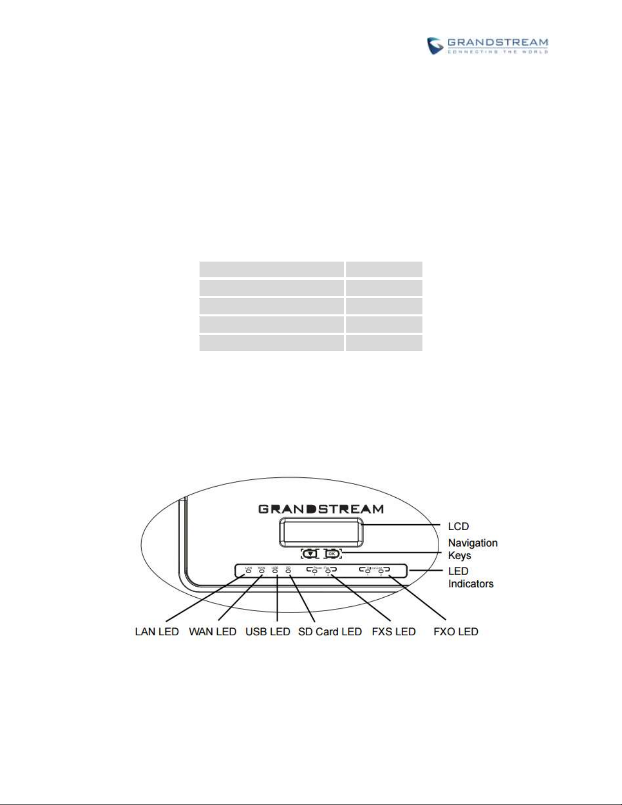
Firmware Version 1.0.0.1
UCM6200 Series IP PBX User Manual
Page 25 of 321
INSTALLATION
Main Case
Yes (1)
Power Adaptor
Yes (1)
Ethernet Cable
Yes (1)
Quick Installation Guide
Yes (1)
GPL License
Yes (1)
Before deploying and configuring the UCM6200 series, the device needs to be properly powered up and
connected to network. This section describes detailed information on installation, connection and warranty
policy of the UCM6200 series.
EQUIPMENT PACKAGING
Table 2: UCM6202/UCM6204 Equipment Packaging
CONNECT YOUR UCM6200
CONNECT THE UCM6202
Figure 1: UCM6202 Front View
Page 27
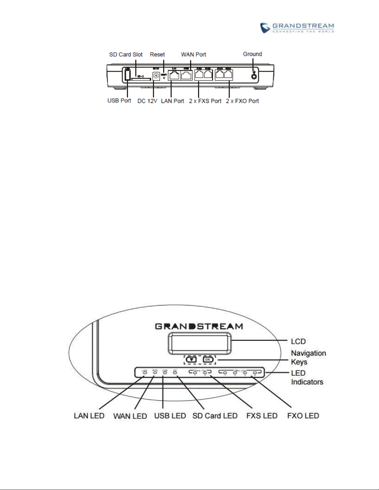
Firmware Version 1.0.0.1
UCM6200 Series IP PBX User Manual
Page 26 of 321
Figure 2: UCM6202 Back View
To set up the UCM6202, follow the steps below:
1. Connect one end of an RJ-45 Ethernet cable into the WAN port of the UCM6202.
2. Connect the other end of the Ethernet cable into the uplink port of an Ethernet switch/hub.
3. Connect the 12V DC power adapter into the 12V DC power jack on the back of the UCM6202. Insert
the main plug of the power adapter into a surge-protected power outlet.
4. Wait for the UCM6202 to boot up. The LCD in the front will show the device hardware information
when the boot process is done.
5. Once the UCM6202 is successfully connected to network, the LED indicator for WAN in the front will
be in solid green and the LCD shows up the IP address.
6. (Optional) Connect PSTN lines from the wall jack to the FXO ports; connect analog lines (phone and
Fax) to the FXS ports.
CONNECT THE UCM6204
Figure 3: UCM6204 Front View
Page 28

Firmware Version 1.0.0.1
UCM6200 Series IP PBX User Manual
Page 27 of 321
Figure 4: UCM6204 Back View
To set up the UCM6204, follow the steps below:
1. Connect one end of an RJ-45 Ethernet cable into the WAN port of the UCM6204.
2. Connect the other end of the Ethernet cable into the uplink port of an Ethernet switch/hub.
3. Connect the 12V DC power adapter into the 12V DC power jack on the back of the UCM6204.
Insert the main plug of the power adapter into a surge-protected power outlet.
4. Wait for the UCM6204 to boot up. The LCD in the front will show the device hardware information
when the boot process is done.
5. Once the UCM6204 is successfully connected to network, the LED indicator for WAN in the front
will be in solid green and the LCD shows up the IP address.
6. (Optional) Connect PSTN lines from the wall jack to the FXO ports; connect analog lines (phone
and Fax) to the FXS ports.
CONNECT THE UCM6208
To set up the UCM6208, follow the steps below:
1. Connect one end of an RJ-45 Ethernet cable into the LAN port of the UCM6208.
2. Connect the other end of the Ethernet cable into the uplink port of an Ethernet switch/hub.
3. Connect the 12V DC power adapter into the 12V DC power jack on the back of the UCM6 208. Insert
the main plug of the power adapter into a surge-protected power outlet.
4. Wait for the UCM6208 to boot up. The LCD in the front will show the device hardware information
when the boot process is done.
5. Once the UCM6208 is successfully connected to network, the LED indicator for NETWORK in the front
will be in solid green and the LCD shows up the IP address.
Page 29
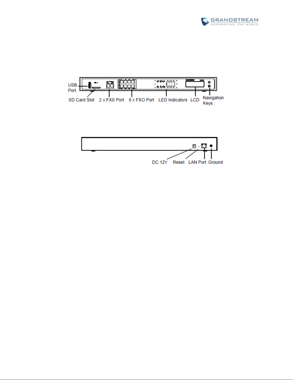
Firmware Version 1.0.0.1
UCM6200 Series IP PBX User Manual
Page 28 of 321
6. (Optional) Connect PSTN lines from the wall jack to the FXO ports; connect analog lines (phone and
Fax) to the FXS ports.
Figure 5: UCM6208 Front View
Figure 6: UCM6208 Back View
SAFETY COMPLIANCES
The UCM6200 series IP PBX complies with FCC/CE and various safety standards. The UCM6200 power
adapter is compliant with the UL standard. Use the universal power adapter provided with the UCM6200
package only. The manufacturer’s warranty does not cover damages to the device caused by unsupported
power adapters.
WARRANTY
If the UCM6200 series IP PBX was purchased from a reseller, please contact the company where the
device was purchased for replacement, repair or refund. If the device was purchased directly from
Grandstream, contact our Technical Support Team for a RMA (Return Materials Authorization) number
before the product is returned. Grandstream reserves the right to remedy warranty policy without prior
notification.
---------------------------------------------------------------------------------------------- ----------------------------------------------
Page 30

Firmware Version 1.0.0.1
UCM6200 Series IP PBX User Manual
Page 29 of 321
Warning:
Use the power adapter provided with the UCM6200 series IP PBX. Do not use a different power adapter as
this may damage the device. This type of damage is not covered under warranty.
--------------------------------------------------------------------------------------------------------------------------------------------
Page 31

Firmware Version 1.0.0.1
UCM6200 Series IP PBX User Manual
Page 30 of 321
Page 32

Firmware Version 1.0.0.1
UCM6200 Series IP PBX User Manual
Page 31 of 321
GETTING STARTED
The UCM6200 series provides LCD interface, LED indication and web GUI configuration interface.
The LCD displays hardware, software and network information. Users could also navigate in the LCD
menu for device information and basic network configuration.
The LED indication at the front of the device provides interface connection and activity status.
The web GUI gives users access to all the configurations and options for UCM6200 series setup.
This section provides step-by-step instructions on how to use the LCD menu, LED indicators and Web GUI
of the UCM6200 series. Once the basic settings are done, users could start making calls from UCM6200
extension registered on a SIP phone as described at the end of this section.
USE THE LCD MENU
Default LCD Display
When the device is powered up, the LCD will show device model (e.g., UCM6204), hardware version
(e.g., V1.0A) and IP address. Press "Down" button and the system time will be displayed as well.
Menu Access
Press "OK" button to start browsing menu options. Please see menu options in [Table 3: LCD Menu
Options].
Menu Navigation
Press the "Down" arrow key to browser different menu options. Press the "OK" button to select an
entry.
Exit
If "Back" option is available in the menu, select it to go back to the previous menu. For "Device Info"
"Network Info" and "Web Info" which do not have "Back" option, simply press the "OK" button to go
back to the previous menu. Also, the LCD will display default idle screen after staying in menu option
for 15 seconds.
LCD Backlight
The LCD backlight will be on upon key pressing. The backlight will go off after the LCD stays in idle for
30 seconds.
Page 33

Firmware Version 1.0.0.1
UCM6200 Series IP PBX User Manual
Page 32 of 321
Table 3: LCD Menu Options
View Events
Critical Events
Other Events
Device Info
Hardware: Hardware version number
Software: Software version number
P/N: Part number
WAN MAC: WAN side MAC address (UCM6202/UCM6204 only)
LAN MAC: LAN side MAC address
Uptime: System up time
Network Info
For UCM6208:
LAN Mode: DHCP, Static IP, or PPPoE
LAN IP: IP address
LAN Subnet Mask
For UCM6202/UCM6204:
WAN Mode: DHCP, Static IP, or PPPoE
WAN IP: IP address
WAN Subnet Mask
LAN IP: IP address
LAN Subnet Mask
Network Menu
For UCM6208:
LAN Mode: Select LAN mode as DHCP, Static IP or PPPoE
Static Route Reset: Click to reset the static route setting
For UCM6202/UCM6204:
WAN Mode: Select WAN mode as DHCP, Static IP or PPPoE
Static Route Reset: Click to reset the static route setting
Factory Menu
Reboot
Factory Reset
LCD Test Patterns
Press "OK" to start. Then press "Down" button to test different LCD
patterns. When done, press "OK" button to exit.
Fan Mode
Select "Auto" or "On".
LED Test Patterns
Page 34

Firmware Version 1.0.0.1
UCM6200 Series IP PBX User Manual
Page 33 of 321
Select "All On" "All Off" or "Blinking" and check LED status.
RTC Test Patterns
Select "2022-02-22 22:22" or "2011-01-11 11:11" to start the RTC
(Real-Time Clock) test pattern. Then check the system time from LCD idle
screen by pressing "DOWN" button, or from web GUI->System
Status->General page. Reboot the device manually after the RTC test is
done.
Hardware Testing
Select "Test SVIP" to perform SVIP test on the device. This is mainly for
factory testing purpose which verifies the hardware connection inside the
device. The diagnostic result will display in the LCD after the test is done.
Web Info
Protocol: Web access protocol. HTTP or HTTPS. By default it's HTTPS
Port: Web access port number. By default it's 8089
SSH Switch
Enable SSH: Enable SSH access.
Disable SSH: Disable SSH access.
By default the SSH access is disabled.
LED Indicator
LED Status
LAN
WAN
USB
SD
FXS (Phone/Fax)
FXO (Telco Line)
Solid: Connected
Flashing: Data Transferring
OFF: Not Connected
USE THE LED INDICATORS
The UCM6200 has LED indicators in the front to display connection status. The following table shows the
status definitions.
Table 4: UCM6202/UCM6204 LED INDICATORS
Page 35

Firmware Version 1.0.0.1
UCM6200 Series IP PBX User Manual
Page 34 of 321
Table 5: UCM6208 LED INDICATORS
LED
LED Status
NETWORK
Solid: Connected
OFF: Not Connected
ACT
USB
SD
Phone (FXS)
Line (FXO)
Solid: Connected
Flashing: Data Transferring
OFF: Not Connected
USE THE WEB GUI
ACCESS WEB GUI
The UCM6200 embedded Web server responds to HTTP/HTTPS GET/POST requests. Embedded HTML
pages allow users to configure the device through a Web browser such as Microsoft IE, Mozilla Firefox,
Google Chrome and etc.
Figure 7: UCM6204 Web GUI Login Page
Page 36

Firmware Version 1.0.0.1
UCM6200 Series IP PBX User Manual
Page 35 of 321
To access the Web GUI:
1. Connect the computer to the same network as the UCM6200.
2. Ensure the device is properly powered up and shows its IP address on the LCD.
3. Open a Web browser on the computer and enter the web GUI URL in the following format:
http(s)://IP-Address:Port
where the IP-Address is the IP address displayed on the UCM6200 LCD.
By default, the protocol is HTTPS and the Port number is 8089.
For example, if the LCD shows 192.168.40.167, please enter the following in your web browser:
https://192.168.40.167:8089
4. Enter the administrator’s login and password to access the Web Configuration Menu. The default
administrator's username and password is "admin" and "admin". It is highly recommended to change
the default password after login for the first time.
----------------------------------------------------------------------------------------------------------------------------- ---------------
Note:
By default, the UCM6200 has "Redirect From Port 80" enabled. Therefore, if users type in the UCM6200 IP
address in the web browser, the web page will be automatically redirected to the page using HTTPS and
port 8089. For example, if the LCD shows 192.168.40.167, please enter 192.168.40.167 in your web
browser and the web page will be redirected to:
https://192.168.40.167:8089
The option "Redirect From Port 80" can be configured under the UCM6200 web GUI->Settings->HTTP
Server.
--------------------------------------------------------------------------------------------------------------------------------------------
Page 37

Firmware Version 1.0.0.1
UCM6200 Series IP PBX User Manual
Page 36 of 321
SETUP WIZARD
When the user logs in the UCM6200 web UI for the first time, a setup wizard will guide the user to set up basic
configuration. Configurations in setup wizard includes: Time zone, Change password, Network settings,
Extensions, Trunk and routes.
During the wizard, the user can quit the setup wizard at any time to start over with manual configuration. At
the last step of the wizard, the user will be provided with summary for review, before the configuration is
loaded. Once the setup is completed, the system is ready to go.
Figure 8: UCM6200 Setup Wizard
Page 38

Firmware Version 1.0.0.1
UCM6200 Series IP PBX User Manual
Page 37 of 321
WEB GUI CONFIGURATIONS
There are four main sections in the Web GUI for users to view the PBX status, configure and manage the
PBX.
Status: Displays PBX status, System Status, System Events and CDR.
PBX: To configure extensions, trunks, call routes, zero config for auto provisioning, call features,
internal options, IAX settings and SIP settings.
Settings: To configure user management, network settings, firewall settings, change password,
LDAP Server, HTTP Server, Email Settings, Time Settings, NTP server, recording storage and login
timeout.
Maintenance: To perform firmware upgrade, backup configurations, cleaner setup, reset/reboot,
syslog setup and troubleshooting.
WEB GUI LANGUAGES
Currently the UCM6200 series web GUI supports English, Simplified Chinese, Traditional Chinese,
Spanish, French, Portuguese, Russian, Italian, Polish, German and etc.
Users can select the displayed language in web GUI login page, or at the upper right of the web GUI after
logging in.
Figure 9: UCM6200 Web GUI Language
Page 39

Firmware Version 1.0.0.1
UCM6200 Series IP PBX User Manual
Page 38 of 321
SAVE AND APPLY CHANGES
Click on "Save" button after configuring the web GUI options in one page. After saving all the changes,
make sure click on "Apply Changes" button on the upper right of the web page to submit all the changes. If
the change requires reboot to take effect, a prompted message will pop up for you to reboot the device.
MAKE YOUR FIRST CALL
Power up the UCM6200 and your SIP end point phone. Connect both devices to the network. Then follow
the steps below to make your first call.
1. Log in the UCM6200 web GUI, go to PBX->Basic/Call Routes->Extensions.
2. Click on "Create New SIP Extension" to create a new extension. You will need User ID, Password and
Voicemail Password information to register and use the extension later.
3. Register the extension on your phone with the SIP User ID, SIP server and SIP Password information.
The SIP server address is the UCM6200 IP address.
4. When your phone is registered with the extension, dial *97 to access the voicemail box. Enter the
Voicemail Password once you hear "Password" voice prompt.
5. Once successfully logged in to the voicemail, you will be prompted with the Voice Mail Main menu.
6. You are successfully connected to the PBX system now.
Page 40

Firmware Version 1.0.0.1
UCM6200 Series IP PBX User Manual
Page 39 of 321
SYSTEM SETTINGS
This section explains configurations for system-wide parameters on the UCM6200. System settings are
under “Settings” tag on UCM6200 web GUI. System settings include User Management, Network Settings,
Firewall, Change Password, LDAP server, HTTP server, Email settings, Time Settings, NTP Server,
Recordings Storage and Login Timeout settings.
USER MANAGEMENT
User management is on web GUI->Settings->User Management page. User could create multiple
accounts for different administrators to log in the UCM6200 web GUI. Additionally, the system will
automatically create user accounts along with creating new extensions for extension users to login to the
web UI using their extension number and password. All existing user accounts for web UI login will be
displayed on User Management page as shown in the following figure.
USER PRIVILEGES
Three privilege levels are supported:
Super Admin
Figure 10: User Management Page Display
Page 41

Firmware Version 1.0.0.1
UCM6200 Series IP PBX User Manual
Page 40 of 321
- This is the highest privilege. Super Admin can access all pages on UCM6200 web GUI, change
configuration for all options and execute all the operations.
- Super Admin can create, edit and delete one or more users with “Admin” privilege
- Super Admin can edit and delete one or more users with “Consumer” privilege
- Super Admin can view operation logs generated by all users.
- By default, the user account “admin” is configured with “Super Admin” privilege and it’s the only
user with “Super Admin” privilege. The User Name and Privilege level cannot be changed or
deleted.
- Super Admin could change its own login password on web UI->Settings->Change Password
page.
- Super Admin could view operations done by all the users in web UI->Settings->User
Management->Operation Log.
Admin
- Users with “Admin” privilege can only be created by “Super Admin” user.
- “Admin” privilege users are not allowed to access the following pages:
Maintenance->Upgrade
Maintenance->Backup
Maintenance->Cleaner
Maintenance->Reset/Reboot
Settings->User Management->Operation Log
- “Admin” privilege users cannot create new users for login.
Consumer
- A user account for web UI login is created automatically by the system when a new extension is
created.
- The user could log in the web UI with the extension number and password to access user
information, extension configuration and CDR of that extension.
CREATE NEW WEB UI USER
When logged in as Super Admin, click on to create a new account for web UI user. The
following dialog will prompt. Configure the parameters as shown in below table.
Page 42

Firmware Version 1.0.0.1
UCM6200 Series IP PBX User Manual
Page 41 of 321
User Name
Configure a username to identify the user which will be required in web UI login.
Letters, digits and underscore are allowed in the user name.
User Password
Configure a password for this user which will be required in web UI login. Letters,
digits and underscore are allowed.
Privilege
This is the role of the web UI user. Currently only “Admin” is supported when
Super Admin creates a new user.
Department
Enter the necessary information to keep a record for this user.
Fax
Email Address
First Name
Last Name
Home Number
Phone Number
Figure 11: Create New User
Table 6: User Management->Create New User
Once created, the Super Admin can edit the users by clicking on or delete the user by clicking on .
Figure 12: User Management – New Users
Page 43

Firmware Version 1.0.0.1
UCM6200 Series IP PBX User Manual
Page 42 of 321
USER PORTAL
The user could log in web UI user portal using the extension number and password. When there is an
extension created in the UCM6200, the corresponding user account for the extension is automatically
created. The user portal allows limited access including user information, extension configuration and CDR
information of the extension. The login username is the extension number and the password is configured
by Super Admin. The following figure shows the dialog of editing the account information by Super Admin.
The User Name must be the extension number and it’s not configurable.
Figure 13: Edit User Information by Super Admin
The following figure shows an example of login page using extension number 1000 as the username.
After login, the web UI displays is shown as below.
Figure 14: User Portal Login
Page 44

Firmware Version 1.0.0.1
UCM6200 Series IP PBX User Manual
Page 43 of 321
Figure 15: User Portal Layout
For the configuration parameter information in each page, please refer to [Table 6: User
Management->Create New User] for options in User Portal->Basic Information->User Information page;
please refer to [EXTENSIONS] for options in User Portal->Basic Information->Extension page; please
refer to [CDR] for User Portal->Basic Information->CDR page.
CONCURRENT MULTI-USER LOGIN
When there are multiple web UI users created, concurrent multi-user login is supported on the UCM6200.
Multiple users could edit options and have configurations take effect simultaneously. However, if different
users are editing the same option or making the same operation (by clicking on “Apply Changes”), a
prompt will pop up as shown in the following figure.
Figure 16: Multiple User Operation Error Prompt
OPERATION LOG
Super Admin has the authority to view operation logs on UCM6200 web GUI->Settings->User
Management->Operation Log page. Operation logs list operations done by all the web UI users, for
example, web UI login, creating trunk, creating outbound rule and etc. There are 6 columns to record the
operation details “Date”, “User Name”, “IP Address”, “Results”, “Page Operation” and “Specific Operation”.
Page 45

Firmware Version 1.0.0.1
UCM6200 Series IP PBX User Manual
Page 44 of 321
Figure 17: Operation Logs
Date
The date and time when the operation is executed.
User Name
The username of the user who performed the operation.
IP Address
The IP address from which the operation is made.
Results
The result of the operation.
Page Operation
The page where the operation is made. For example, login, logout, delete user,
create trunk and etc.
Specific Operation
Click on to view the options and values configured by this operation.
The operation log can be sorted and filtered for easy access. Click on the header of each column to sort.
For example, clicking on "Date" will sort the logs according to operation date and time. Clicking on "Date"
again will reverse the order.
Table 7: Operation Log Column Header
User could also filter the operation logs by time condition, IP address and/or username. Configure these
conditions and then click on .
Page 46

Firmware Version 1.0.0.1
UCM6200 Series IP PBX User Manual
Page 45 of 321
Figure 18: Operation Logs Filter
The above figure shows an example that operations made by user “support” on device with IP
192.168.40.173 from 2014-11-01 00:00 to 2014-11-06 15:38 are filtered out and displayed.
To delete operation logs, users can perform filtering first and then click on to
delete the filtered result of operation logs. Or users can click on to delete all
operation logs at once.
CHANGE PASSWORD
After logging in the UCM6200 web UI for the first time, it is highly recommended for users to change the
default password "admin" to a more complicated password for security purpose. Follow the steps below to
change the Web UI access password.
1. Go to Web UI->Settings->User Management-> Change Password page.
2. Enter the old password first.
3. Enter the new password and re-type the new password to confirm. The new password has to be at
least 4 characters. The maximum length of the password is 30 characters.
4. Configure the Email Address that is used when login credential is lost.
5. Click on "Save" and the user will be automatically logged out.
6. Once the web page comes back to the login page again, enter the username "admin" and the new
password to login.
Page 47

Firmware Version 1.0.0.1
UCM6200 Series IP PBX User Manual
Page 46 of 321
Enter Old Password
Enter the Old Password for UCM6200
Enter New Password
Enter the New Password for UCM6200
Retype New
Password
Retype the New Password for UCM6200
Email Address
Configure the Email address for UCM6200. In case login credential is lost, Email
address is used to retrieve login credential
Figure 19 : Change Password
CHANGE BINDNG EMAIL
UCM6200 allows user to configure binding email in case login password is lost. UCM6200 login credential
will be sent to the designated email address. The feature can be found under web UI->Settings->User
Management->Change Binding Email.
Figure 20: Change Binding Email
Page 48

Firmware Version 1.0.0.1
UCM6200 Series IP PBX User Manual
Page 47 of 321
Table 8: Change Binding Email option
Enter the password
of the account
Enter the current login user credential for UCM6200
Email Address
Email Address is used to retrieve password when password is lost
Method
Select "Route", "Switch" or "Dual" mode on the network interface of UCM6200.
The default setting is "Route".
Route
WAN port interface will be used for uplink connection. LAN port interface will
be used to serve as router.
Switch
WAN port interface will be used for uplink connection. LAN port interface will
be used as bridge for PC connection.
Dual
Both ports can be used for uplink connection. Users will need assign LAN 1 or
LAN 2 as the default interface in option "Default Interface" and configure
"Gateway IP" for this interface.
NETWORK SETTINGS
After successfully connecting the UCM6200 to the network for the first time, users could login the Web GUI
and go to Settings->Network Settings to configure the network parameters for the device.
Additional network functions and settings are available for UCM6202 and UCM6204:
UCM6202/UCM6204 supports Route/Switch/Dual mode functions.
In this section, all the available network setting options are listed for all models. Select each tab in web
GUI->Settings->Network Settings page to configure LAN settings, WAN settings (UCM6202/UCM6204
only), 802.1X and Port Forwarding (UCM6202/UCM6204 only).
BASIC SETTINGS
Please refer to the following tables for basic network configuration parameters on UCM6202/UCM6204,
and UCM6208 respectively.
Table 9: UCM6202/UCM6204 Network Settings->Basic Settings
Page 49

Firmware Version 1.0.0.1
UCM6200 Series IP PBX User Manual
Page 48 of 321
Preferred DNS Server
Enter the preferred DNS server address. If Preferred DNS is used, UCM will try to
use it as Primary DNS server.
WAN (when "Method" is set to "Route")
IP Method
Select DHCP, Static IP, or PPPoE. The default setting is DHCP.
IP Address
Enter the IP address for static IP settings. The default setting is 192.168.0.160.
Subnet Mask
Enter the subnet mask address for static IP settings. The default setting is
255.255.0.0.
Gateway IP
Enter the gateway IP address for static IP settings. The default setting is 0.0.0.0.
DNS Server 1
Enter the DNS server 1 address for static IP settings. The default setting is
0.0.0.0.
DNS Server 2
Enter the DNS server 2 address for static IP settings.
User Name
Enter the user name to connect via PPPoE.
Password
Enter the password to connect via PPPoE.
Layer 2 QoS
802.1Q/VLAN Tag
Assign the VLAN tag of the layer 2 QoS packets for WAN port. The default value
is 0.
Layer 2 QoS 802.1p
Priority Value
Assign the priority value of the layer 2 QoS packets for WAN port. The default
value is 0.
LAN (when Method is set to "Route")
IP Address
Enter the IP address assigned to LAN port. The default setting is 192.168.2.1.
Subnet Mask
Enter the subnet mask. The default setting is 255.255.255.0.
DHCP Server Enable
Enable or disable DHCP server capability. The default setting is "Yes".
DNS Server 1
Enter DNS server address 1. The default setting is 8.8.8.8.
DNS Server 2
Enter DNS server address 2. The default setting is 208.67.222.222.
Allow IP Address
From
Enter the DHCP IP Pool starting address. The default setting is 192.168.2.100.
Allow IP Address To
Enter the DHCP IP Pool ending address. The default setting is 192.168.2.254.
Default IP Lease Time
Enter the IP lease time (in seconds). The default setting is 43200.
LAN (when Method is set to "Switch")
IP Method
Select DHCP, Static IP, or PPPoE. The default setting is DHCP.
IP Address
Enter the IP address for static IP settings. The default setting is 192.168.0.160.
Subnet Mask
Enter the subnet mask address for static IP settings. The default setting is
255.255.0.0.
Gateway IP
Enter the gateway IP address for static IP settings. The default setting is 0.0.0.0.
DNS Server 1
Enter the DNS server 1 address for static IP settings. The default setting is
0.0.0.0.
DNS Server 2
Enter the DNS server 2 address for static IP settings.
Page 50

Firmware Version 1.0.0.1
UCM6200 Series IP PBX User Manual
Page 49 of 321
User Name
Enter the user name to connect via PPPoE.
Password
Enter the password to connect via PPPoE.
Layer 2 QoS
802.1Q/VLAN Tag
Assign the VLAN tag of the layer 2 QoS packets for LAN port. The default value is
0.
Layer 2 QoS 802.1p
Priority Value
Assign the priority value of the layer 2 QoS packets for LAN port. The default
value is 0.
LAN 1 / LAN 2 (when Method is set to "Dual")
Default Interface
If "Dual" is selected as "Method", users will need assign the default interface to be
LAN 1 (mapped to UCM6202 WAN port) or LAN 2 (mapped to UCM6202 LAN
port) and then configure network settings for LAN 1/LAN 2. The default interface is
LAN 2.
IP Method
Select DHCP, Static IP, or PPPoE. The default setting is DHCP.
IP Address
Enter the IP address for static IP settings. The default setting is 192.168.0.160.
Subnet Mask
Enter the subnet mask address for static IP settings. The default setting is
255.255.0.0.
Gateway IP
Enter the gateway IP address for static IP settings when the port is assigned as
default interface. The default setting is 0.0.0.0.
DNS Server 1
Enter the DNS server 1 address for static IP settings. The default setting is
0.0.0.0.
DNS Server 2
Enter the DNS server 2 address for static IP settings.
User Name
Enter the user name to connect via PPPoE.
Password
Enter the password to connect via PPPoE.
Layer 2 QoS
802.1Q/VLAN Tag
Assign the VLAN tag of the layer 2 QoS packets for LAN port. The default value is
0.
Layer 2 QoS 802.1p
Priority Value
Assign the priority value of the layer 2 QoS packets for LAN port. The default
value is 0.
Preferred DNS Server
Enter the preferred DNS server address. If Preferred DNS is used, UCM will try to
use it as Primary DNS server.
IP Method
Select DHCP, Static IP, or PPPoE. The default setting is DHCP.
IP Address
Enter the IP address for static IP settings.
Subnet Mask
Enter the subnet mask address for static IP settings.
Gateway IP
Enter the gateway IP address for static IP settings.
Table 10: UCM6208 Network Settings->Basic Settings
Page 51

Firmware Version 1.0.0.1
UCM6200 Series IP PBX User Manual
Page 50 of 321
DNS Server 1
Enter the DNS server 1 address for static IP settings.
DNS Server 2
Enter the DNS server 2 address for static IP settings.
User Name
Enter the user name to connect via PPPoE.
Password
Enter the password to connect via PPPoE.
Layer 2 QoS
802.1Q/VLAN Tag
Assign the VLAN tag of the layer 2 QoS packets for LAN port. The default value is
0.
Layer 2 QoS 802.1p
Priority Value
Assign the priority value of the layer 2 QoS packets for LAN port. The default
value is 0.
Method: Route
When the UCM6200 has method set to Route in network settings, WAN port interface is used for
uplink connection and LAN port interface is used as a router. Please see a sample diagram below.
Figure 21: UCM6200 Network Interface Method: Route
Page 52

Firmware Version 1.0.0.1
UCM6200 Series IP PBX User Manual
Page 51 of 321
Method: Switch
WAN port interface is used for uplink connection; LAN port interface is used as bridge for PC
connection.
Figure 22: UCM6200 Network Interface Method: Switch
Method: Dual
Both WAN port and LAN port are used for uplink connection. Users will need assign LAN 1 or LAN 2 as
the default interface in option "Default Interface" and configure "Gateway IP" if static IP is used for this
interface.
Page 53

Firmware Version 1.0.0.1
UCM6200 Series IP PBX User Manual
Page 52 of 321
Figure 23: UCM6200 Network Interface Method: Dual
802.1X
IEEE 802.1X is an IEEE standard for port-based network access control. It provides an authentication
mechanism to device before the device is allowed to access Internet or other LAN resources. The
UCM6200 supports 802.1X as a supplicant/client to be authenticated. The following diagram and figure
show UCM6200 uses 802.1X mode “EAP-MD5” on WAN port as client in the network to access Internet.
Figure 24: UCM6200 Using 802.1X as Client
Page 54

Firmware Version 1.0.0.1
UCM6200 Series IP PBX User Manual
Page 53 of 321
802.1X Mode
Select 802.1X mode. The default setting is "Disable". The supported 802.1X
mode are:
EAP-MD5
EAP-TLS
EAP-PEAPv0/MSCHAPv2
Identity
Enter 802.1X mode identity information.
MD5 Password
Enter 802.1X mode MD5 password information.
802.1X Certificate
Select 802.1X certificate from local PC and then upload.
802.1X Client
Certificate
Select 802.1X client certificate from local PC and then upload.
Figure 25: UCM6200 Using 802.1X EAP-MD5
The following table shows the configuration parameters for 802.1X on UCM6200. Identity and MD5
password are required for authentication, which should be provided by the network administrator obtained
from the RADIUS server. If “EAP-TLS” or “EAP-PEAPv0/MSCHAPv2” is used as the 802.1X mode, users
will also need upload 802.1X CA Certificate and 802.1X Client Certificate, which should be also generated
from the RADIUS server.
Table 11 : UCM6200 Network Settings->802.1X
STATIC ROUTES
The UCM6200 provides users static routing capability that allows the device to use manually configured
routes, rather than information only from dynamic routing or gateway configured in the UCM6200 web
GUI->Network Settings->Basic Settings to forward traffic. It can be used to define a route when no other
routes are available or necessary, or used in complementary with existing routing on the UCM6200 as a
failover backup, and etc.
Page 55

Firmware Version 1.0.0.1
UCM6200 Series IP PBX User Manual
Page 54 of 321
Click on to create a new static route. The configuration parameters are listed
Destination
Configure the destination IP address or the destination IP subnet for the
UCM6200 to reach using the static route.
Example:
IP address - 192.168.66.4
IP subnet - 192.168.66.0
Netmask
Configure the subnet mask for the above destination address. If left blank, the
default value is 255.255.255.255.
Example:
255.255.255.0
Gateway
Configure the gateway address so that the UCM6200 can reach the destination
via this gateway. Gateway address is optional.
Example:
192.168.40.5
Interface
Specify the network interface on the UCM6200 to reach the destination using the
static route.
LAN interface is eth0; WAN interface is eth1.
in the table below.
Once added, users can select to edit the static route.
Select to delete the static route.
Table 12: UCM6200 Network Settings->Static Routes
Static routes configuration can be reset from LCD menu->Network Menu.
The following diagram shows a sample application of static route usage on UCM6204.
Page 56

Firmware Version 1.0.0.1
UCM6200 Series IP PBX User Manual
Page 55 of 321
Figure 26: UCM6204 Static Route Sample
The network topology of the above diagram is as below:
Network 192.168.69.0 has IP phones registered to UCM6204 LAN 1 address
Network 192.168.40.0 has IP phones registered to UCM6204 LAN 2 address
Network 192.168.66.0 has IP phones registered to UCM6204 via VPN
Network 192.168.40.0 has VPN connection established with network 192.168.66.0
In this network, by default the IP phones in network 192.168.69.0 are unable to call IP phones in network
192.168.66.0 when registered on different interfaces on the UCM6204. Therefore, we need configure a
static route on the UCM6204 so that the phones in isolated networks can make calls between each other.
Figure 27: UCM6204 Static Route Configuration
Page 57

Firmware Version 1.0.0.1
UCM6200 Series IP PBX User Manual
Page 56 of 321
PORT FORWORDING
WAN Port
Specify the WAN port number or a range of WAN ports. Up to 8 ports can be
configured.
Note:
When it is set to a range, WAN port and LAN port must be configured with the
same range, such as WAN port: 1000-1005 and LAN port: 1000-1005, and access
from WAN port will be forwarded to the LAN port with the same port number, for
example, WAN port 1000 will be port forwarding to LAN port 1000.
LAN IP
Specify the LAN IP address.
LAN Port
Specify the LAN port number or a range of LAN ports.
Note:
When it is set to a range, WAN port and LAN port must be configured with the
same range, such as WAN port: 1000-1005 and LAN port: 1000-1005, and access
from WAN port will be forwarded to the LAN port with the same port number, for
example, WAN port 1000 will be port forwarding to LAN port 1000.
Protocol Type
Select protocol type "UDP Only", "TCP Only" or "TCP/UDP" for the forwarding in
the selected port. The default setting is "UDP Only".
The UCM network interface supports router function which provides users the ability to do port forwarding.
If the UCM6202/UCM6204 LAN mode is set to "Route" under web GUI->Settings->Network
Settings->Basic Settings page, port forwarding is available for configuration.
The port forwarding configuration is under web GUI->Settings->Network Settings->Port Forwarding
page. Please see related settings in the table below.
Table 13: UCM6202/UCM6204 Network Settings->Port Forwarding
The following figures demonstrate a port forwarding example to provide phone’s web UI access to public
side.
The UCM6202/UCM6204 network mode is set to “Route”
The UCM6202/UCM6204 WAN port is connected to uplink switch, with a public IP address configured,
e.g. 1.1.1.1.
The UCM6202/UCM6204 LAN port provides DHCP pool that connects to multiple phone devices in the
LAN network 192.168.2.x. The UCM6202/UCM6204 is used as a router, with gateway address
192.168.2.1
Page 58

Firmware Version 1.0.0.1
UCM6200 Series IP PBX User Manual
Page 57 of 321
There is a GXP2160 connected under the LAN interface network of the UCM6202/UCM6204. It
obtains IP address 192.168.2.100 from UCM6200 DHCP pool
On the UCM6202/UCM6204 web UI->Settings->Network Settings->Port Forwarding, configure a
port forwarding entry as the figure shows below.
WAN Port: This is the port opened up on the WAN side for access purpose.
LAN IP: This is the GXP2160 IP address, under the LAN interface network of the
UCM6202/UCM6204.
Protocol Type: We select TCP here for web UI access using HTTP.
Figure 28: UCM6202/UCM6204 Port Forwarding Configuration
This will allow users to access the GXP2160 web UI from public side, by typing in address “1.1.1.1:8088”.
Page 59

Firmware Version 1.0.0.1
UCM6200 Series IP PBX User Manual
Page 58 of 321
Figure 29: GXP2160 Web Access Using UCM6202 Port Forwarding
DDNS SETTINGS
DDNS setting allows user to access UCM6200 via domain name instead of IP address.
The UCM supports DDNS service from the following DDNS provider:
dydns.org
noip.com
freedns.afraid.org
zoneedit.com
oray.net
Here is an example of using noip.com for DDNS.
1. Register domain in DDNS service provider. Please note the UCM6200 needs to have public IP access.
Page 60

Firmware Version 1.0.0.1
UCM6200 Series IP PBX User Manual
Page 59 of 321
Figure 30: Register Domain Name on noip.com
2. On web UI->Settings->Network Settings->DDNS Settings, enable DDNS service and configure
username, password and host name.
3. Now you can use domain name instead of IP address to connect to the UCM6200 web UI.
Figure 31: UCM6200 DDNS Setting
Page 61

Firmware Version 1.0.0.1
UCM6200 Series IP PBX User Manual
Page 60 of 321
Figure 32: Using Domain Name to Connect to UCM6200
FIREWALL
The UCM6200 provides users firewall configurations to prevent certain malicious attack to the UCM6200
system. Users could configure to allow, restrict or reject specific traffic through the device for security and
bandwidth purpose. The UCM6200 also provides Fail2ban feature for authentication errors in SIP
REGISTER, INVITE and SUBSCRIBE. To configure firewall settings in the UCM6200, go to Web
UI->Settings->Firewall page.
STATIC DEFENSE
Under Web GUI->Settings->Firewall->Static Defense page, users will see the following information:
Current service information with port, process and type.
Typical firewall settings.
Custom firewall settings.
The following table shows a sample current service status running on the UCM6200.
Page 62

Firmware Version 1.0.0.1
UCM6200 Series IP PBX User Manual
Page 61 of 321
Table 14: UCM6200 Firewall->Static Defense->Current Service
Port
Process
Type
Protocol or Service
7777
Asterisk
tcp/IPv4
SIP
389
Slapd
tcp/IPv4
LDAP
22
Dropbear
tcp/IPv4
SSH
80
Lighthttpd
tcp/IPv4
HTTP
8089
Lighthttpd
tcp/IPv4
HTTPS
69
Opentftpd
udp/IPv4
TFTP
9090
Asterisk
udp/IPv4
SIP
6060
zero_config
udp/IPv4
UCM6200 zero_config service
5060
Asterisk
udp/IPv4
SIP
4569
Asterisk
udp/IPv4
SIP
5353
zero_config
udp/IPv4
UCM6200 zero_config service
37435
Syslogd
udp/IPv4
Syslog
Ping Defense
Enable
If enabled, ICMP response will not be allowed for Ping request. The default
setting is disabled. To enable or disable it, click on the check box for the LAN or
WAN (UCM6202/UCM6204) interface.
Ping-of-Death
Defense Enable
Enable to prevent Ping-of-Death attack to the device. The default setting is
disabled. To enable or disable it, click on the check box for the LAN or WAN
(UCM6202/UCM6204) interface.
For typical firewall settings, users could configure the following options on the UCM6200.
Table 15: Typical Firewall Settings
Under "Custom Firewall Settings", users could create new rules to accept, reject or drop certain traffic
going through the UCM6200. To create new rule, click on "Create New Rule" button and a new window will
pop up for users to specify rule options.
Right next to "Create New Rule" button, there is a checkbox for option "Reject Rules". If it’s checked, all
the rules will be rejected except the firewall rules listed below. In the firewall rules, only when there is a rule
that meets all the following requirements, the option "Reject Rules" will be allowed to check:
Action: "Accept"
Type "In"
Destination port is set to the system login port (e.g., by default 8089)
Protocol is not UDP
Page 63

Firmware Version 1.0.0.1
UCM6200 Series IP PBX User Manual
Page 62 of 321
Rule Name
Specify the Firewall rule name to identify the firewall rule.
Action
Select the action for the Firewall to perform.
ACCEPT
REJECT
DROP
Type
Select the traffic type.
IN
If selected, users will need specify the network interface "LAN" or "WAN"
(for UCM6202/UCM6204) for the incoming traffic.
OUT
Service
Select the service type.
FTP
SSH
Telnet
TFTP
HTTP
LDAP
Custom
If "Custom" is selected, users will need specify Source (IP and port),
Destination (IP and port) and Protocol (TCP, UDP or Both) for the service.
Please note if the source or the destination field is left blank, it will be used
as "Anywhere".
Figure 33: Create New Firewall Rule
Table 16: Firewall Rule Settings
Save the change and click on "Apply" button. Then submit the configuration by clicking on "Apply
Changes" on the upper right of the web page. The new rule will be listed at the bottom of the page with
sequence number, rule name, action, protocol, type, source, destination and operation. More operations
below:
Page 64

Firmware Version 1.0.0.1
UCM6200 Series IP PBX User Manual
Page 63 of 321
Click on to edit the rule
Dynamic Defense
Enable
Enable dynamic defense. The default setting is disabled.
Periodical Time
Interval
Configure the dynamic defense periodic time interval (in minutes). If the
number of TCP connections from a host exceeds the connection threshold
within this period, this host will be added into Blacklist. The valid value is
between 1 and 59 when dynamic defense is turned on. The default setting is
59.
Blacklist Update
Interval
Configure the blacklist update time interval (in seconds). The default setting is
120.
Connection
Threshold
Configure the connection threshold. Once the number of connections from the
same host reaches the threshold, it will be added into the blacklist. The default
setting is 100.
Dynamic Defense
Whitelist
Configure the dynamic defense whitelist.
For example,
192.168.1.3
192.168.1.4
Click on to delete the rule
DYNAMIC DEFENSE
Dynamic defense is supported on the UCM6200 series. It can blacklist hosts dynamically when the LAN
mode is set to "Route" under web GUI->Settings->Network Settings->Basic Settings page. If enabled,
the traffic coming into the UCM6200 can be monitored, which helps prevent massive connection attempts
or brute force attacks to the device. The blacklist can be created and updated by the UCM6200 firewall,
which will then be displayed in the web page. Please refer to the following table for dynamic defense
options on the UCM6200.
Table 17: UCM6200 Firewall Dynamic Defense
The following figure shows a configuration example like this:
If a host at IP address 192.168.40.7 initiates more than 20 TCP connections to the UCM6200 within 1
minute, it will be added into UCM6200 blacklist.
This host 192.168.40.7 will be blocked by the UCM6200 for 300 seconds.
Page 65

Firmware Version 1.0.0.1
UCM6200 Series IP PBX User Manual
Page 64 of 321
Since IP address 192.168.40.5 is in whitelist, if the host at IP address 192.168.40.5 initiates more than
Global Settings
Enable Fail2Ban
Enable Fail2Ban. The default setting is disabled. Please make sure both "Enable
Fail2Ban" and "Asterisk Service" are turned on in order to use Fail2Ban for SIP
authentication on the UCM6200.
Banned Duration
Configure the duration (in seconds) for the detected host to be banned. The
default setting is 300. If set to -1, the host will be always banned.
Max Retry Duration
Within this duration (in seconds), if a host exceeds the max times of retry as
defined in "MaxRetry", the host will be banned. The default setting is 5.
MaxRetry
Configure the number of authentication failures during "Max Retry Duration"
before the host is banned. The default setting is 10.
Fail2Ban Whitelist
Configure IP address, CIDR mask or DNS host in the whiltelist. Fail2Ban will not
20 TCP connections to the UCM6200 within 1 minute, it will not be added into UCM6200 blacklist. It
can still establish TCP connection with the UCM6200.
Figure 34: Configure Dynamic Defense
FAIL2BAN
Fail2Ban feature on the UCM6200 provides intrusion detection and prevention for authentication errors in
SIP REGISTER, INVITE and SUBSCRIBE. Once the entry is detected within "Max Retry Duration", the
UCM6200 will take action to forbid the host for certain period as defined in "Banned Duration". This feature
helps prevent SIP brute force attacks to the PBX system.
Table 18: Fail2Ban Settings
Page 66

Firmware Version 1.0.0.1
UCM6200 Series IP PBX User Manual
Page 65 of 321
ban the host with matching address in this list. Up to 5 addresses can be added
into the list.
Local Settings
Asterisk Service
Enable Asterisk service for Fail2Ban. The default setting is disabled. Please make
sure both "Enable Fail2Ban" and "Asterisk Service" are turned on in order to use
Fail2Ban for SIP authentication on the UCM6200.
Protocol
Configure the listening port number for the service. Currently only 5060 (for UDP)
is supported.
MaxRetry
Configure the number of authentication failures during "Max Retry Duration"
before the host is banned. The default setting is 10. Please make sure this option
is properly configured as it will override the "MaxRetry" value under "Global
Settings".
LDAP SERVER
The UCM6200 has an embedded LDAP server for users to manage corporate phonebook in a centralized
manner.
By default, the LDAP server has generated the first phonebook with PBX DN
"ou=pbx,dc=pbx,dc=com" based on the UCM6200 user extensions already.
Users could add new phonebook with a different Phonebook DN for other external contacts. For
example, "ou=people,dc=pbx,dc=com".
All the phonebooks in the UCM6200 LDAP server have the same Base DN "dc=pbx,dc=com".
Term Explanation:
cn= Common Name
ou= Organization Unit
dc= Domain Component
These are all parts of the LDAP data Interchange Format, according to RFC 2849, which is how the LDAP
tree is filtered.
If users have the Grandstream phone provisioned by the UCM6200, the LDAP directory will be set up on
the phone and can be used right away for users to access all phonebooks.
Additionally, users could manually configure the LDAP client settings to manipulate the built-in LDAP
server on the UCM6200. If the UCM6200 has multiple LDAP phonebooks created, in the LDAP client
configuration, users could use "dc=pbx,dc=com" as Base DN to have access to all phonebooks on the
Page 67

Firmware Version 1.0.0.1
UCM6200 Series IP PBX User Manual
Page 66 of 321
UCM6200 LDAP server, or use a specific phonebook DN, for example "ou=people,dc=pbx,dc=com", to
access to phonebook with Phonebook DN "ou=people,dc=pbx,dc=com " only.
UCM can also act as a LDAP client to download phonebook entries from other LDAP server.
To access LDAP server and client settings, go to Web GUI->Settings->LDAP Server.
LDAP SERVER CONFIGURATIONS
The following figure shows the default LDAP server configurations on the UCM6200.
Figure 35: LDAP Server Configurations
The UCM6200 LDAP server supports anonymous access (read-only) by default. Therefore the LDAP client
doesn't have to configure username and password to access the phonebook directory. The "Root DN" and
"Root Password" here are for LDAP management and configuration where users will need provide for
authentication purpose before modifying the LDAP information.
The default phonebook list in this LDAP server can be viewed and edited by clicking on for the first
phonebook under LDAP Phonebook.
Figure 36: Default LDAP Phonebook DN
Page 68

Firmware Version 1.0.0.1
UCM6200 Series IP PBX User Manual
Page 67 of 321
Figure 37: Default LDAP Phonebook Attributes
LDAP PHONEBOOK
Users could use the default phonebook, edit the default phonebook, add new phonebook, import
phonebook on the LDAP server as well as export phonebook from the LDAP server. The first phonebook
with default phonebook dn "ou=pbx,dc=pbx,dc=com" displayed on the LDAP server page is for extensions
in this PBX. Users cannot add or delete contacts directly. The contacts information will need to be modified
via Web GUI->PBX->Basic/Call Routes->Extensions first. The default LDAP phonebook will then be
updated automatically.
Figure 38: LDAP Server->LDAP Phonebook
Page 69

Firmware Version 1.0.0.1
UCM6200 Series IP PBX User Manual
Page 68 of 321
Add new phonebook
A new sibling phonebook of the default PBX phonebook can be added by clicking on "Add" under
"LDAP Phonebook" section.
Figure 39: Add LDAP Phonebook
Configure the "Phonebook Prefix" first. The "Phonebook DN" will be automatically filled in. For example, if
configuring "Phonebook Prefix" as "people", the "Phonebook DN" will be filled with
"ou=people,dc=pbx,dc=com".
Once added, users can select to edit the phonebook attributes and contact list (see figure below), or
select to delete the phonebook.
Figure 40: Edit LDAP Phonebook
Page 70

Firmware Version 1.0.0.1
UCM6200 Series IP PBX User Manual
Page 69 of 321
Import phonebook from your computer to LDAP server
Click on “Import Phonebook” and a dialog will prompt as shown in the figure below.
Figure 41: Import Phonebook
The file to be imported must be a CSV file with UTF-8 encoding. Users can open the CSV file with
Notepad and save it with UTF-8 encoding.
Here is how a sample file looks like. Please note “Account Number” and “Phonebook DN” fields are
required. Users could export a phonebook file from the UCM6200 LDAP phonebook section first and
use it as a sample to start with.
The Phonebook DN field is the same “Phonebook Prefix” entry as when the user clicks on “Add” to
create a new phonebook. Therefore, if the user enters “phonebook” in “Phonebook DN” field in the
CSV file, the actual phonebook DN “ou=phonebook,dc=pbx,dc=com” will be automatically created by
the UCM6200 once the CSV file is imported.
In the CSV file, users can specify different phonebook DN fields for different contacts. If the phonebook
DN already exists on the UCM6200 LDAP Phonebook, the contacts in the CSV file will be added into
the existing phonebook. If the phonebook DN doesn’t exist on the UCM6200 LDAP Phonebook, a new
phonebook with this phonebook DN will be created.
The sample phonebook CSV file in above picture will result in the following LDAP phonebook in the
Figure 42: Phonebook CSV File Format
Page 71

Firmware Version 1.0.0.1
UCM6200 Series IP PBX User Manual
Page 70 of 321
UCM6200.
Figure 43: LDAP Phonebook After Import
As the default LDAP phonebook with DN “ou=pbx,dc=pbx,dc=com” cannot be edited or deleted in
LDAP phonebook section, users cannot import contacts with Phonebook DN field “pbx” if existed in the
CSV file.
Export phonebook to your computer from UCM6200 LDAP server
Select the checkbox for the LDAP phonebook and then click on “Export Selected Phonebook” to
export the selected phonebook. The exported phonebook can be used as a record or a sample CSV
file for the users to add more contacts in it and import to the UCM6200 again.
LDAP CLIENT CONFIGURATIONS
The configuration on LDAP client is similar when you use other LDAP servers. Here we provide an
example on how to configure the LDAP client on the SIP end points to use the default PBX phonebook.
Assuming the server base dn is "dc=pbx,dc=com", configure the LDAP clients as follows (case
insensitive):
Server Address: LDAP server IP address
Figure 44: Export Selected LDAP Phonebook
Page 72

Firmware Version 1.0.0.1
UCM6200 Series IP PBX User Manual
Page 71 of 321
Base DN: dc=pbx,dc=com
User Name: cn= “LDAP server login name”, dc=pbx, dc=com [matching LDAP server format]
Password: “LDAP server login password”
Filter: (|(CallerIDName=%)(AccountNumber=%))
Port: 389
The following figure gives a sample configurations for UCM6200 acting as a LDAP client.
Figure 45: LDAP Client Configurations
To configure Grandstream IP phones as the LDAP client, please refer to the following example:
Server Address: The IP address or domain name of the UCM6200
Base DN: dc=pbx,dc=com
User Name: Please leave this field empty
Password: Please leave this field empty
LDAP Name Attribute: CallerIDName Email Department FirstName LastName
LDAP Number Attribute: AccountNumber MobileNumber HomeNumber Fax
LDAP Number Filter: (AccountNumber=%)
LDAP Name Filter: (CallerIDName=%)
LDAP Display Name: AccountNumber CallerIDName
LDAP Version: If existed, please select LDAP Version 3
Port: 389
The following figure shows the configuration information on a Grandstream GXP2200 to successfully use
the LDAP server as configured in Figure 35: LDAP Server Configurations.
Page 73

Firmware Version 1.0.0.1
UCM6200 Series IP PBX User Manual
Page 72 of 321
HTTP SERVER
The UCM6200 embedded web server responds to HTTP/HTTPS GET/POST requests. Embedded HTML
pages allow the users to configure the PBX through a Web browser such as Microsoft IE, Mozilla Firefox
and Google Chrome. By default, the PBX can be accessed via HTTPS using Port 8089 (e.g.,
https://192.168.40.50:8089). Users could also change the access protocol and port as preferred under
Web GUI->Settings->HTTP Server.
Figure 46: GXP2200 LDAP Phonebook Configuration
Page 74

Firmware Version 1.0.0.1
UCM6200 Series IP PBX User Manual
Page 73 of 321
Table 19: HTTP Server Settings
Redirect From Port 80
Enable or disable redirect from port 80. On the PBX, the default access
protocol is HTTPS and the default port number is 8089. When this option
is enabled, the access using HTTP with Port 80 will be redirected to
HTTPS with Port 8089. The default setting is "Enable".
Protocol Type
Select HTTP or HTTPS. The default setting is "HTTPS". This is also the
protocol used for zero config when the end point device downloads the
config file from the UCM6200.
Port
Specify port number to access the HTTP server. The default port number
is 8089.
TLS Enable
Enable or disable TLS during transferring/submitting your Email to other
SMTP server. The default setting is "Yes".
Type
Select Email type.
MTA: Mail Transfer Agent. The Email will be sent from the configured
domain. When MTA is selected, there is no need to set up SMTP
server for it or no user login is required. However, the Emails sent
from MTA might be considered as spam by the target SMTP server.
Client: Submit Emails to the SMTP server. A SMTP server is required
and users need login with correct credentials.
Domain
Specify the domain name to be used in the Email when using type "MTA".
Server
Specify the SMTP server when using type "Client".
Username
Username is required when using type "Client". Normally it's the Email
address.
Password
Password to login for the above Username (Email address) is required
when using type "Client".
Display Name
Specify the display name in the FROM header in the Email.
Sender
Specify the sender's Email address.
For example, pbx@example.mycompany.com.
Once the change is saved, the web page will be redirected to the login page using the new URL. Enter the
username and password to login again.
EMAIL SETTINGS
The Email application on the UCM6200 can be used to send out alert event Emails, Fax (Fax-To -Email),
Voicemail (Voicemail-To-Email) and etc. The configuration parameters can be accessed via Web
GUI->Settings->Email Settings.
Table 20: Email Settings
Page 75

Firmware Version 1.0.0.1
UCM6200 Series IP PBX User Manual
Page 74 of 321
The following figure shows a sample Email settings on the UCM6200, assuming the Email is using
smtp.gmail.com as the SMTP server.
Figure 47: UCM6200 Email Settings
Once the configuration is finished, click on "Test". In the prompt, fill in a valid Email address to send a test
Email to verify the Email settings on the UCM6200.
TIME SETTINGS
AUTO TIME UPDATING
The current system time on the UCM6200 is displayed on the upper right of the web page. It can also be
found under Web GUI->Status->System Status->General.
To configure the UCM6200 to update time automatically, go to Web GUI->Settings->Time
Settings->Time Auto Updating.
----------------------------------------------------------------------------------------------------------------------------- ---------------
Note:
The configurations under Web GUI->Settings->Time Settings->Time Auto Updating page require
reboot to take effect. Please consider configuring auto time updating related changes when setting up the
UCM6200 for the first time to avoid service interrupt after installation and deployment in production.
----------------------------------------------------------------------------------------------------------------------------- ---------------
Page 76

Firmware Version 1.0.0.1
UCM6200 Series IP PBX User Manual
Page 75 of 321
Table 21: Time Auto Updating
Remote NTP Server
Specify the URL or IP address of the NTP server for the UCM6200 to
synchronize the date and time. The default NTP server is
ntp.ipvideotalk.com.
Enable DHCP Option 2
If set to "Yes", the UCM6200 is allowed to get provisioned for Time Zone
from DHCP Option 2 in the local server automatically. The default setting
is "Yes".
Enable DHCP Option 42
If set to "Yes", the UCM6200 is allowed to get provisioned for NTP Server
from DHCP Option 42 in the local server automatically. This will override
the manually configured NTP Server. The default setting is "Yes".
Time Zone
Select the proper time zone option so the UCM6200 can display correct
time accordingly.
If "Self-Defined Tome Zone" is selected, please specify the time zone
parameters in "Self-Defined Time Zone" field as described in below
option.
Self-Defined Time Zone
If "Self-Defined Time Zone" is selected in "Time Zone" option, users will
need define their own time zone following the format below.
The syntax is: std offset dst [offset], start [/time], end [/time]
Default is set to: MTZ+6MDT+5,M4.1.0,M11.1.0
MTZ+6MDT+5
This indicates a time zone with 6 hours offset and 1 hour ahead for DST,
which is U.S central time. If it is positive (+), the local time zone is west of
the Prime Meridian (A.K.A: International or Greenwich Meridian); If it is
negative (-), the local time zone is east.
M4.1.0,M11.1.0
The 1st number indicates Month: 1,2,3.., 12 (for Jan, Feb, .., Dec).
The 2nd number indicates the nth iteration of the weekday: (1st Sunday,
3rd Tuesday…). Normally 1, 2, 3, 4 are used. If 5 is used, it means the
last iteration of the weekday.
The 3rd number indicates weekday: 0,1,2,..,6 ( for Sun, Mon,
Tues, ... ,Sat).
Therefore, this example is the DST which starts from the First Sunday of
April to the 1st Sunday of November.
Page 77

Firmware Version 1.0.0.1
UCM6200 Series IP PBX User Manual
Page 76 of 321
SET TIME MANUALLY
To manually set the time on the UCM6200, go to Web UI->Settings->Time Settings->Set Time Manually.
The format is YYYY-MM-DD HH:MI:SS.
Figure 48: Set Time Manually
--------------------------------------------------------------------------------------------------------------------------------------------
Note:
Manually setup time will take effect immediately after saving and applying change in the web UI. If users
would like to reboot the UCM6200 and keep the manually setup time setting, please make sure "Remote
NTP Server", "Enable DHCP Option 2" and "Enable DHCP Option 42" options under Web
GUI->Settings->Time Settings->Time Auto Updating page are unchecked or set to empty. Otherwise,
time auto updating settings in this page will take effect after reboot.
----------------------------------------------------------------------------------------------------------------------------- ---------------
OFFICE TIME
On the UCM6200, the system administrator can define "office time", which can be used to configure time
condition for extension call forwarding schedule and inbound rule schedule. To configure office time, go to
Web UI->Settings->Time Settings->Office Time. Click on "Create New Office Time" to create an office
time.
Page 78

Firmware Version 1.0.0.1
UCM6200 Series IP PBX User Manual
Page 77 of 321
Start Time
Configure the start time for office hour.
End Time
Configure the end time for office hour
Week
Select the work days in one week.
Show Advanced Options
Check this options to show advanced options. Once selected, please
specify "Month" and "Day" below.
Month
Select the months for office time.
Day
Select the work days in one month.
Figure 49: Create New Office Time
Table 22: Create New Office Time
Select "Start Time", "End Time" and the day for the "Week" for the office time. The system administrator
can also define month and day of the month as advanced options. Once done, click on "Save" and then
"Apply Change" for the office time to take effect. The office time will be listed in the web page as the figure
shows below.
Page 79

Firmware Version 1.0.0.1
UCM6200 Series IP PBX User Manual
Page 78 of 321
Figure 50: Settings->Time Settings->Office Time
Click on to edit the office time.
Click on to delete the office time.
Click on "Delete Selected Office Times" to delete multiple selected office times at once.
HOLIDAY
On the UCM6200, the system administrator can define "holiday", which can be used to configure time
condition for extension call forwarding schedule and inbound rule schedule. To configure holiday, go to
Web UI->Settings->Time Settings->Holiday. Click on "Create New Holiday" to create holiday time.
Figure 51: Create New Holiday
Page 80

Firmware Version 1.0.0.1
UCM6200 Series IP PBX User Manual
Page 79 of 321
Table 23: Create New Holiday
Name
Specify the holiday name to identify this holiday.
Holiday Memo
Create a note for the holiday.
Month
Select the month for the holiday.
Day
Select the day for the holiday.
Show Advanced Options
Check this option to show advanced options. If selected, please specify
the days as holiday in one week below.
Week
Select the days as holiday in one week.
Enter holiday "Name" and "Holiday Memo" for the new holiday. Then select "Month" and "Day". The
system administrator can also define days in one week as advanced options. Once done, click on "Save"
and then "Apply Change" for the holiday to take effect. The holiday will be listed in the web page as the
figure shows below.
Figure 52: Settings->Time Settings->Holiday
Click on to edit the holiday.
Click on to delete the holiday.
Click on "Delete Selected Holidays" to delete multiple selected holidays at once.
----------------------------------------------------------------------------------------------------------------------------- ---------------
Note:
For more details on how to use office time and holiday, please refer to the link below:
http://www.grandstream.com/sites/default/files/Resources/How_to_use_office_time_and_holiday_UCM62
00.pdf
----------------------------------------------------------------------------------------------------------------------------- ---------------
Page 81

Firmware Version 1.0.0.1
UCM6200 Series IP PBX User Manual
Page 80 of 321
NTP SERVER
The UCM6200 can be used as a NTP server for the NTP clients to synchronize their time with. To
configure the UCM6200 as the NTP server, set "Enable NTP server" to "Yes" under web
GUI->Settings->NTP Server. On the client side, point the NTP server address to the UCM6200 IP
address or host name to use the UCM6200 as the NTP server.
RECORDINGS STORAGE
The UCM6200 supports call recordings automatically or manually and the recording files can be saved in
external storage plugged in the UCM6200 or on the UCM6200 locally. To manage the recording storage,
users can go to UCM6200 web GUI->Settings->Recordings Storage page and select whether to store
the recording files in USB Disk, SD card or locally on the UCM6200.
If “Enable Auto Change” is selected, the recording files will be automatically saved in the available
USB Disk or SD card plugged into the UCM6200. If both USB Disk and SD card are plugged in, the
recording files will be always saved in the USB Disk.
If “Local” is selected, the recordings will be stored in UCM6200 internal storage.
If “USB Disk” or “SD Card” is selected, the recordings will be stored in the corresponding plugged in
external storage device. Please note the options “USB Disk” and “SD Card” will be displayed only if
they are plugged into the UCM6200.
Figure 53: Settings->Recordings Storage
Page 82

Firmware Version 1.0.0.1
UCM6200 Series IP PBX User Manual
Page 81 of 321
Once “USB Disk” or “SD Card” is selected, click on “OK”. The user will be prompted to confirm to copy
the local files to the external storage device.
Figure 54: Recordings Storage Prompt Information
Click on “OK” to continue. The users will be prompted a new dialog to select the categories for the files
to be copied over.
On the UCM6200, recording files are generated and exist in 3 categories: normal call recording files,
conference recording files, and call queue recording files. Therefore users have the following options
when select the categories to copy the files to the external device:
- Recording Files: Copy the normal recording files to the external device.
- Conference: Copy the conference recording files to the external device.
- Queue: Copy the call queue recording files to the external device.
- All: Copy all recording files to the external device.
Figure 55: Recording Storage Category
Page 83

Firmware Version 1.0.0.1
UCM6200 Series IP PBX User Manual
Page 82 of 321
LOGIN TIMEOUT SETTINGS
After the user logs in the UCM6200 web UI, the user will be automatically logged out after certain timeout.
This timeout value can be specified under UCM100 web GUI->Settings->Login Timeout Settings page.
The “User Login Timeout” value is in minute and the default setting is 10 minutes. If the user doesn’t make
any operation on web UI within the timeout, the user will be logged out automatically. After that, the web UI
will be redirected to the login page and the user will need to enter username and password to log in.
If set to 0, there is no timeout for the web UI login session and the user will not be automatically logged out.
Figure 56: Login Timeout Settings
Page 84

Firmware Version 1.0.0.1
UCM6200 Series IP PBX User Manual
Page 83 of 321
GOOGLE SERVICE SETTINGS SUPPORT
UCM6200 now supports Google OAuth 2.0 authentication. This feature is used for supporting UCM6200
conference scheduling system. Once OAuth 2.0 is enabled, UCM6200 conference system can access Google
calendar to schedule or update conference.
Google Service Settings can be found under web GUI-> Settings-> Google Service Settings-> Google
Service Settings.
Figure 57: Google Service Settings->OAuth2.0 Authentication
If you already have OAuth2.0 project set up on Google Developers web page, please use your existing
login credential for “OAuth2.0 Client ID” and “OAuth2.0 Client Secret” in the above figure for the UCM6200
to access Google Service.
If you do not have OAuth2.0 project set up yet, please following the steps below to create new project and
obtain credentials:
1. Go to Google Developers page https://console.developers.google.com/start Create a New Project in
Google Developers page.
Page 85

Firmware Version 1.0.0.1
UCM6200 Series IP PBX User Manual
Page 84 of 321
Figure 58: Google Service->New Project
2. Enable Calendar API from API Library.
3. Click “Credentials” on the left drop down menu to create new OAuth2.0 login credentials.
4. Use the newly created login credential to fill in “OAuth2.0 Client ID” and “OAuth2.0 Client Secret”.
5. Click “Get Authentication Code” to obtain authentication code from Google Service.
Figure 59: Google Service->Create New Credential
Page 86

Firmware Version 1.0.0.1
UCM6200 Series IP PBX User Manual
Page 85 of 321
Figure 60: Google Service->OAuth2.0 Login
6. Now UCM6200 is connected with Google Service.
Page 87

Firmware Version 1.0.0.1
UCM6200 Series IP PBX User Manual
Page 86 of 321
Page 88

Firmware Version 1.0.0.1
UCM6200 Series IP PBX User Manual
Page 87 of 321
PROVISIONING
OVERVIEW
Grandstream SIP Devices can be configured via Web interface as well as via configuration file through
TFTP/HTTP/HTTPS download. All Grandstream SIP devices support a proprietary binary format
configuration file and XML format configuration file. The UCM6200 provides a Plug and Play mechanism to
auto-provision the Grandstream SIP devices in a zero configuration manner by generating XML config file
and having the phone to download it within LAN area. This allows users to finish the installation with ease
and start using the SIP devices in a managed way.
To provision a phone, three steps are involved, i.e., discovery, configuration and provisioning. This section
explains how Zero Config works on the UCM6200. The settings for this feature can be accessed via Web
UI->PBX->Zero Config.
CONFIGURATION ARCHITECTURE FOR END POINT DEVICE
Started from firmware version 1.0.7.10, the end point device configuration in zero config is divided into the
following three layers with priority from the lowest to the highest:
Global
This is the lowest layer. Users can configure the most basic options that could apply to all
Grandstream SIP devices during provisioning via Zero config.
Model
In this layer, users can define model-specific options for the configuration template.
Device
This is the highest layer. Users can configure device-specific options for the configuration for individual
device here.
Each layer also has its own structure in different levels. Please see figure below. The details for each layer
are explained in sections [GLOBAL CONFIGURATION], [MODEL CONFIGURATION] and [DEVICE
CONFIGURATION].
Page 89

Firmware Version 1.0.0.1
UCM6200 Series IP PBX User Manual
Page 88 of 321
Figure 61: Zero Config Configuration Architecture for End Point Device
The configuration options in model layer and device layer have all the option in global layers already, i.e.,
the options in global layer is a subset of the options in model layer and device layer. If an option is set in all
three layers with different values, the highest layer value will override the value in lower layer. For example,
if the user selects English for Language setting in Global Policy and Spanish for Language setting in
Default Model Template, the language setting on the device to be provisioned will use Spanish as model
layer has higher priority than global layer. To sum up, configurations in higher layer will always
override the configurations for the same options/fields in the lower layer when presented at the
same time.
After understanding the zero config configuration architecture, users could configure the available options
for end point devices to be provisioned by the UCM6200 by going through the three layers. This
configuration architecture allows users to set up and manage the Grandstream end point devices in the
same LAN area in a centralized way.
AUTO PROVISIONING SETTINGS
By default, the Zero Config feature is enabled on the UCM6200 for auto provisioning. Three methods of
auto provisioning are used.
Page 90

Firmware Version 1.0.0.1
UCM6200 Series IP PBX User Manual
Page 89 of 321
Figure 62: UCM6200 Zero Config
SIP SUBSCRIBE
When the phone boots up, it sends out SUBSCRIBE to a multicast IP address in the LAN. The
UCM6200 discovers it and then sends a NOTIFY with the XML config file URL in the message body.
The phone will then use the path to download the config file generated in the UCM6200 and take the
new configuration.
DHCP OPTION 66
This method should be used on the UCM6202/UCM6204 because only the UCM6202/UCM6204 have
WAN and LAN port with LAN port supporting the router function. When the phone restarts (by default
DHCP Option 66 is turned on), it will send out a DHCP DISCOVER request. The UCM6202 receives it
and returns DHCP OFFER with the config server path URL in Option 66, for example,
https://192.168.2.1:8089/zccgi/. The phone will then use the path to download the config file generated
in the UCM6200.
mDNS
Page 91

Firmware Version 1.0.0.1
UCM6200 Series IP PBX User Manual
Page 90 of 321
When the phone boots up, it sends out mDNS query to get the TFTP server address. The UCM6200
Enable Zero Config
Enable or disable the zero config feature on the PBX. The default setting
is enabled.
Enable Automatic
Configuration Assignment
By default, this is disabled. If disabled, when SIP device boots up, the
UCM6200 will not send the SIP device the URL to download the config file
and therefore the SIP device will not be automatically provisioned by the
UCM6200.
Note:
When disabled, SIP devices can still be provisioned by manually sending
NOTIFY from the UCM6200 which will include the XML config file URL for
the SIP device to download.
Automatically Assign
Extension
If enabled, when the device is discovered, the PBX will automatically
assign an extension within the range defined in "Zero Config Extension
Segment" to the device. The default setting is disabled.
Zero Config Extension
Click on the link "Zero Config Extension Segment" to specify the
will respond with its own address. The phone will then send TFTP request to download the XML config
file from the UCM6200.
To start the auto provisioning process, under Web GUI->PBX->Zero Config->Zero Config Settings, fill in
the auto provision information.
Figure 63: Auto Provision Settings
Table 24: Auto Provision Settings
Page 92

Firmware Version 1.0.0.1
UCM6200 Series IP PBX User Manual
Page 91 of 321
Segment
extension range to be assigned if "Automatically Assign Extension" is
enabled. The default range is 5000-6299. Zero Config Extension
Segment range can be defined in web UI->PBX->Internal
Options->General page->Extension Preference section: "Auto Provision
Extensions".
Enable Pick Extension
If enabled, the extension list will be sent out to the device after receiving
the device's request. This feature is for the GXP series phones that
support selecting extension to be provisioned via phone's LCD. The
default setting is disabled.
Pick Extension Segment
Click on the link "Pick Extension Segment" to specify the extension list to
be sent to the device. The default range is 4000 to 4999. Pick Extension
Segment range can be defined in web UI->PBX->Internal
Options->General page->Extension Preference section: "Pick
Extensions".
Pick Extension Period
(hour):
Specify the number of minutes to allow the phones being provisioned to
pick extensions.
Please make sure an extension is manually assigned to the phone or "Automatically Assign Extension" is
enabled during provisioning. After the configuration on the UCM6200 web GUI, click on "Save" and "Apply
Changes". Once the phone boots up and picks up the config file from the UCM6200, it will take the
configuration right away.
DISCOVERY
Users could manually discover the device by specifying the IP address or scanning the entire LAN network.
Three methods are supported to scan the devices.
PING
ARP
SIP Message (NOTIFY)
Click on "Auto Discover" under web UI-> PBX-> Zero Config->Zero Config, fill in the "Scan Method" and
"Scan IP". The IP address segment will be automatically filled in based on the network mask detected on
the UCM6200. If users need scan the entire network segment, enter 255 (for example, 192.168.40.255)
instead of a specific IP address. Then click on "Save" to start discovering the devices within the same
network. To successfully discover the devices, "Zero Config" needs to be enabled on the UCM6200 web
GUI->PBX->Zero Config->Auto Provisioning Settings.
Page 93

Firmware Version 1.0.0.1
UCM6200 Series IP PBX User Manual
Page 92 of 321
Figure 64: Auto Discover
The following figure shows a list of discovered phones. The MAC address, IP Address, Extension (if
assigned), Version, Vendor, Model, Connection Status, Create Config, Options (Edit/Delete/Update) are
displayed in the list.
Figure 65: Discovered Devices
GLOBAL CONFIGURATION
GLOBAL POLICY
Global configuration will apply to all the connected Grandstream SIP end point devices in the same LAN
with the UCM6200 no matter what the Grandstream device model it is. It is divided into two levels:
Web UI->PBX->Zero Config->Global Policy
Web UI->PBX->Zero Config->Global Templates.
Global Templates configuration has higher priority to Global Policy configuration.
Global Policy can be accessed in web GUI->PBX->Zero Config->Global Policy page. On the top of the
configuration table, users can select category in the "Options" dropdown list to quickly navigate to the
category. The categories are:
Page 94

Firmware Version 1.0.0.1
UCM6200 Series IP PBX User Manual
Page 93 of 321
Localization: configure display language, data and time.
Language settings
Language
Select the LCD display language on the SIP end device.
Date and Time
Date Format
Configure the date display format on the SIP end device’s LCD.
Time Format
Configure the time display in 12-hour or 24-hour format on the SIP end
device’s LCD.
NTP Server
Configure the URL or IP address of the NTP server. The SIP end device
may obtain the date and time from the server.
Time Zone
Configure the time zone used on the SIP end device.
Phone Settings: configure dial plan, call features, NAT, call progress tones and etc.
Contact List: configure LDAP and XML phonebook download.
Maintenance: configure upgrading, web access, Telnet/SSH access and syslog.
Network Settings: configure IP address, QoS and STUN settings.
Customization: customize LCD screen wallpaper for the supported models.
Select the checkbox on the left of the parameter you would like to configure to active the dropdown list for
this parameter.
Figure 66: Global Policy Categories
The following tables list the Global Policy configuration parameters for the SIP end device.
Table 25: Global Policy Parameters->Localization
Page 95

Firmware Version 1.0.0.1
UCM6200 Series IP PBX User Manual
Page 94 of 321
Table 26: Global Policy Parameters->Phone Settings
Default Call Settings
Dial Plan
Configure the default dial plan rule. For syntax and examples, please
refer to user manual of the SIP devices to be provisioned for more details.
Enable Call Features
When enabled, “Do Not Disturb”, “Call Forward” and other call features
can be used via the local feature code on the phone. Otherwise, the ITSP
feature code will be used.
Use # as Dial Key
If set to “Yes”, pressing the number key “#” will immediately dial out the
input digits.
Auto Answer by Call-info
If set to "Yes", the phone will automatically turn on the speaker phone to
answer incoming calls after a short reminding beep, based on the SIP
Call-Info header sent from the server/proxy.
The default setting is enabled.
NAT Traversal
Configure which NAT traversal mechanism will be enabled on the
endpoint device.
If set to "STUN" and STUN server is configured, the phone system will
periodically send STUN message to the SUTN server to get the public IP
address of its NAT environment and keep the NAT port open. STUN will
not work if the NAT is symmetric type.
If set to “Keep-alive”, the phone system will send the STUN packets to
maintain the connection that is first established during registration of the
phone. The “Keep-alive” packets will fool the NAT device into keeping the
connection open and this allows the host server to send SIP requests
directly to the registered phone.
If it needs to use OpenVPN to connect host server, it needs to set it to
“VPN”.
If the firewall and the SIP device behind the firewall are both able to use
UPNP, it can be set to “UPNP”. The both parties will negotiate to use
which port to allow SIP through.
The default setting is "Keep-alive".
Use Random Port
Configure whether to allow the endpoint device to use random ports for
both SIP and RTP messages. This is usually necessary when multiple
phones are behind the same full cone NAT. The default setting is "No".
Note: This parameter must be set to "No" for Direct IP Calling to work.
General Settings
Call Progress Tones
Configure call progress tones including ring tone, dial tone, second dial
tone, message waiting tone, ring back tone, call waiting tone, busy tone
and reorder tone using the following syntax:
f1=val, f2=val[, c=on1/ off1[- on2/ off2[- on3/ off3]]];
Page 96

Firmware Version 1.0.0.1
UCM6200 Series IP PBX User Manual
Page 95 of 321
Frequencies are in Hz and cadence on and off are in 10ms).
“on” is the period (in ms) of ringing while “off” is the period of silence.
Up to three cadences are supported.
Please refer to user manual of the SIP devices to be provisioned for
more details
HEADSET Key Mode
Select “Default Mode” or “Toggle Headset/Speaker” for the Headset key.
Please refer to user manual of the SIP devices to be provisioned for more
details.
LDAP Phonebook
Source
Select "Manual" or "PBX" as the LDAP configuration source.
If "Manual" is selected, the LDAP configuration below will be applied
to the SIP end device.
If "PBX" is selected, the LDAP configuration built-in from UCM6200
web UI->Settings->LDAP Server will be applied.
Address
Configure the IP address or DNS name of the LDAP server.
Port
Configure the LDAP server port. The default value is 389.
Base DN
This is the location in the directory where the search is requested to
begin. Example:
dc=grandstream, dc=com
ou=Boston, dc=grandstream, dc=com
User Name
Configure the bind "Username" for querying LDAP servers. The field can
be left blank if the LDAP server allows anonymous binds.
Password
Configure the bind "Password" for querying LDAP servers. The field can
be left blank if the LDAP server allows anonymous binds.
Number Filter
Configure the filter used for number lookups. Please refer to user manual
for more details.
Name Filter
Configure the filter used for name lookups. Please refer to user manual
for more details.
Version
Select the protocol version for the phone to send the bind requests. The
default value is 3.
Name Attribute
Specify the "name" attributes of each record which are returned in the
LDAP search result. Example:
gn
cn sn description
Number Attribute
Specify the "number" attributes of each record which are returned in the
Table 27: Global Policy Parameters->Contact List
Page 97

Firmware Version 1.0.0.1
UCM6200 Series IP PBX User Manual
Page 96 of 321
LDAP search result. Example:
telephoneNumber
telephoneNumber Mobile
Display Name
Configure the entry information to be shown on phone's LCD. Up to 3
fields can be displayed. Example:
%cn %sn %telephoneNumber
Max Hits
Specify the maximum number of results to be returned by the LDAP
server. Valid range is 1 to 3000. The default value is 50.
Search Timeout
Specify the interval (in seconds) for the server to process the request and
client waits for server to return. Valid range is 0 to 180. The default value
is 30.
Sort Results
Specify whether the searching result is sorted or not. The default setting is
No.
Incoming Calls
Configure to enable LDAP number searching when receiving calls. The
default setting is No.
Outgoing Calls
Configure to enable LDAP number searching when making calls. The
default setting is No.
Lookup Display Name
Configures the display name when LDAP looks up the name for incoming
call or outgoing call. It must be a subset of the LDAP Name Attributes.
XML Phonebook
Phonebook XML Server
Select the source of the phonebook XML server.
Disable
Disable phonebook XML downloading.
Manual
Once selected, users need specify downloading protocol HTTP,
HTTPS or TFTP and the server path to download the phonebook
XML file. The server path could be IP address or URL, with up to 256
characters.
Local UCM Server
Once selected, click on the Server Path field to upload the phonebook
XML file. Please note: after uploading the phonebook XML file to the
server, the original file name will be used as the directory name and
the file will be renamed as phonebook.xml under that directory.
Phonebook Download
Interval
Configure the phonebook download interval (in Minute). If set to 0,
automatic download will be disabled. Valid range is 5 to 720.
Remove manually-edited
entries on download
If set to "Yes", when XML phonebook is downloaded, the entries added
manually will be automatically removed.
Page 98

Firmware Version 1.0.0.1
UCM6200 Series IP PBX User Manual
Page 97 of 321
Table 28: Global Policy Parameters->Maintenance
Upgrade and Provision
Firmware Source
Firmware source via ZeroConfig provisioning could a URL for external
server address, local UCM directory or USB media if plugged in to the
UCM6200.
Select a source to get the firmware file:
URL
If select to use URL to upgrade, complete the configuration for the
following four parameters: “Upgrade Via”, “Server Path”, “File Prefix”
and “File Postfix”.
Local UCM Server
Firmware can be uploaded to the UCM6200 internal storage for
firmware upgrade. If selected, click on “Manage Storage” icon next to
“Directory” option, upload firmware file and select directory for the
end device to retrieve the firmware file.
Local USB Media
If selected, the USB storage device needs to be plugged into the
UCM6200 and the firmware file must be put under a folder named
“ZC_firmware” in the USB storage root directory.
Local SD Card Media
If selected, an SD card needs to be plugged into the UCM6200 and
the firmware file must be put under a folder named “ZC_firmware” in
the USB storage root directory.
Upgrade via
When URL is selected as firmware source, configure upgrade via TFTP,
HTTP or HTTPS.
Server Path
When URL is selected as firmware source, configure the firmware
upgrading server path.
File Prefix
When URL is selected as firmware source, configure the firmware file
prefix. If configured, only the firmware with the matching encrypted prefix
will be downloaded and flashed into the phone, if URL is selected as
firmware source.
File Postfix
When URL is selected as firmware source, configure the firmware file
postfix. If configured, only the configuration file with the matching
encrypted postfix will be downloaded and flashed into the phone.
Allow DHCP Option 43/66
If DHCP option 43 or 66 is enabled on the LAN side, the TFTP server can
be redirected.
Automatic Upgrade
If enabled, the endpoint device will automatically upgrade if a new
firmware is detected. Users can select automatic upgrading by day, by
week or by minute.
Page 99

Firmware Version 1.0.0.1
UCM6200 Series IP PBX User Manual
Page 98 of 321
By week
Once selected, specify the day of the week to check HTTP/TFTP
server for firmware upgrades or configuration files changes.
By day
Once selected, specify the hour of the day to check the HTTP/TFTP
server for firmware upgrades or configuration files changes.
By minute
Once selected, specify the interval X that the SIP end device will
request for new firmware every X minutes.
Firmware Upgrade Rule
Specify how firmware upgrading and provisioning request to be sent.
Web Access
Admin Password
Configure the administrator password for admin level login.
End-User Password
Configure the end-user password for the end user level login.
Web Access Mode
Select HTTP or HTTPS as the web access protocol.
Web Server Port
Configure the port for web access. The valid range is 1 to 65535.
Security
Disable Telnet/SSH
Enable Telnet/SSH access for the SIP end device. If the SIP end device
supports Telnet access, this option controls the Telnet access of the
device; if the SIP end device supports SSH access, this option controls
the SSH access of the device.
Syslog
Syslog Server
Configure the URL/IP address for the syslog server.
Syslog Level
Select the level of logging for syslog.
Send SIP Log
Configure whether the SIP log will be included in the syslog message.
Basic Settings
IP Address
Configure how the SIP end device shall obtain the IP address. DHCP or
PPPoE can be selected.
DHCP
Once selected, users can specify the Host Name (option 12) of the
SIP end device as DHCP client, and Vendor Class ID (option 60)
used by the client and server to exchange vendor class ID
information.
PPPoE
Once selected, users need specify the Account ID, Password and
Service Name for PPPoE.
Advanced Setting
Table 29: Global Policy Parameters->Network Settings
Page 100

Firmware Version 1.0.0.1
UCM6200 Series IP PBX User Manual
Page 99 of 321
Layer 3 QoS
Define the Layer 3 QoS parameter. This value is used for IP Precedence,
Diff-Serv or MPLS. Valid range is 0-63.
Layer 2 QoS Tag
Assign the VLAN Tag of the Layer 2 QoS packets. Valid range is 0 -4095.
Layer 2 QoS Priority Value
Assign the priority value of the Layer 2 QoS packets. Valid range is 0-7.
STUN Server
Configure the IP address or Domain name of the STUN server. Only
non-symmetric NAT routers work with STUN.
Keep Alive Interval
Specify how often the phone will send a blank UDP packet to the SIP
server in order to keep the "ping hole" on the NAT router to open. Valid
range is 10-160.
Wallpaper
Screen Resolution 1024 x
600
Check this option if the SIP end device shall use 1024 x 600 resolution for
the LCD screen wallpaper.
Source
Configure the location where wallpapers are stored.
File
If "URL" is selected as source, specify the URL of the wallpaper file. If
"Local UCM Server" is selected as source, click to upload wallpaper
file to the UCM6200.
Screen Resolution 800 x 400
Check this option if the SIP end device shall use 800 x 400 resolution for
the LCD screen wallpaper.
Source
Configure the location where wallpapers are stored.
File
If "URL" is selected as source, specify the URL of the wallpaper file. If
"Local UCM Server" is selected as source, click to upload wallpaper
file to the UCM6200.
Screen Resolution 480 x 272
Check this option if the SIP end device shall use 480 x 272 resolution for
the LCD screen wallpaper.
Source
Configure the location where wallpapers are stored.
File
If "URL" is selected as source, specify the URL of the wallpaper file. If
"Local UCM Server" is selected as source, click to upload wallpaper
file to the UCM6200.
Screen Resolution 320 x 240
Check this option if the SIP end device supports 320 x 240 resolution for
the LCD screen wallpaper.
Source
Table 30: Global Policy Parameters->Customization
 Loading...