

Page 1

Grandstream Networks, Inc.
HT–286
Analog Telephone Adaptor
HT–286 User Manual www.grandstream.com
Firmware Version 1.1.0.31 support@grandstream.com
Page 2

TABLE OF CONTENTS
HT-286 User Manual
WELCOME....................................................................................................................................................4
SAFETY COMPLIANCES.................................................................................................................................4
WARRANTY..................................................................................................................................................4
INSTALLATION.............. ............................................. .................................................................................5
EQUIPMENT PACKAGING...............................................................................................................................5
CONNECTING YOUR ATA........................................................................................................................... ..5
FIGURE 1: CONNECTING THE HT286............................................................................................................5
THREE EASY STEPS TO INSTALL THE HT–286................................................................................................6
FIGURE 2: HT286 CONNECTION DIAGRAM ...................................................................................................6
PRODUCT OVERVIEW................................................................................................................................7
KEY FEATURES............................................................................................................................................7
BASIC OPERATIONS.................................................................... ..............................................................9
GET FAMILIAR WITH VOICE PROMPT .............................................................................................................9
PLACING A PHONE CALL.................................................................................... .........................................10
Phone or Extension Numbers............ ..... ... ..... ...... .. ...... ..... ... ..... ..... ... ..... ... ..... ...... .. ...... ...10
Direct IP Calls ....................... ... ......................................................................................11
CALL HOLD................................................................................................................................................11
CALL WAITING ...........................................................................................................................................11
CALL TRANSFER .................................................................... ....................................................................11
3-WAY CONFERENCING ..............................................................................................................................12
CALL FEATURES......................................................................................................................................13
T.38 FAX.....................................................................................................................................................13
LED LIGHT PATTERN INDICATION.........................................................................................................13
CONFIGURATION GUIDE .........................................................................................................................15
CONFIGURING HT–286 THROUGH VOICE PROMPT.......................................................................................15
CONFIGURING HT–286 WITH WEB BROWSER .............................................................................................15
Access the Web Configuration Menu........................................... .. .................................15
End User Configuration..................................................................................................15
Advanced User Configuration........................... ... ...........................................................18
SAVING THE CONFIGURATION CHANGES ................................................ .....................................................25
REBOOTING THE HT–286 FROM REMOTE ................................... ................................................................25
CONFIGURATION THROUGH A CENTRAL SERVER..........................................................................................25
SOFTWARE UPGRADE.............................................................................................................................26
FIRMWARE UPGRADE THROUGH TFTP/HTTP.............................................................................................26
CONFIGURATION FILE DOWNLOAD..............................................................................................................27
FIRMWARE AND CONFIGURATION FILE PREFIX AND POSTFIX........................................................................27
MANAGING FIRMWARE AND CONFIGURATION FILE DOWNLOAD .....................................................................27
RESTORE FACTORY DEFAULT SETTING..............................................................................................28
TABLE O F FIGURES
HT-286 User Manual
Figure 1: Connecting the HT286 ............ ..... ... ..... ...... .. ...... ..... ... ..... ... ..... ..... ... ..... ... ..... ...... .. ...... . ...5
Figure 2: HT286 Connection Diagram ..........................................................................................6
Grandstream Networks, Inc. HT–286 User Manual Page 2 of 28
Firmware 1.1.0.31 Last Updated: 1/2009
Page 3

T
ABLE OF TABLES
HT-286 User Manual
T
ABLE 1: DEFINITIONS OF THE HT–286 CONNECTORS .....................................................................................5
ABLE 2: HT–286 TECHNICAL SPECIFICATIONS ...... .........................................................................................7
T
ABLE 3: HT–286 HARDWARE SPECIFICATIONS...............................................................................................8
T
T
ABLE 4: HT–286 IVR MENU DEFINITIONS......................................................................................................9
ABLE 5: IVR ERROR REPORT......................................................................................................................10
T
T
ABLE 6: HT–286 CALL FEATURE DEFINITIONS .............................................................................................13
ABLE 7: HT–286 LED DEFINITIONS.............................................................................................................14
T
ABLE 8: HT–286 BASIC CONFIGURATION SETTINGS DEFINITIONS.................................................................16
T
T
ABLE 9: HT–286 DEVICE STATUS PAGE DEFINITIONS...................................................................................17
T
ABLE 10: HT–286 ADVANCED CONFIGURATION PAGE DEFINITIONS ............................................... ...............18
C
ONFIGURATION GUI INTERFACE EXAMPLES
HT–286 User Manual
(http://www.grandstream.com/user_manuals/GUI/GUI_HT286.rar
)
1. SCREENSHOT OF LOGIN PAGE
CREENSHOT OF STATUS PAGE
2. S
CREENSHOT OF BASIC SETTINGS CONFIGURATION PAGE
3. S
CREENSHOT OF ADVANCED SETTING1 CONFIGURATION PAGE
4. S
5. S
CREENSHOT OF ADVANCED SETTING2 CONFIGURATION PAGE
6. S
CREENSHOT OF SAVED CONFIGURATION CHANGES
CREENSHOT OF REBOOT PAGE
7. S
Grandstream Networks, Inc. HT–286 User Manual Page 3 of 28
Firmware 1.1.0.31 Last Updated: 1/2009
Page 4

Welcome
Congratulations on becoming an owner of HandyTone-286. You made an excellent choice and we hope
you will enjoy all its capabilities.
Grandstream's award-wining HandyTone-286 is innovative Analog Telephone Adaptor that offers a rich
set of functionality and superb sound quality at ultra-affordable price. They are fully compatible with SIP
industry standard and can interoperate with many other SIP compliant devices and softw are on the
market.
SAFETY COMPLIANCES
The HT–286 complies with FCC/CE and various safety standards. The HT–286 power adaptor is
compliant with UL standard. Only use the universal power adapter provided with the HT–286 package.
The manufacturer’s warranty does not cover damages to the phone caused by unsupported power
adaptors.
ARRANTY
W
If you purchased your HT–286 from a reseller, please contact the company where you purchased your
phone for replacement, repair or refund. If you purchased the product directly from Grandstream, contact
your Grandstream Sales and Service Representative for a RMA (Return Materials Authorization) number
before you return the product. Grandstream reserves the right to remedy warranty policy without prior
notification.
Warning: Please do not use a different power adaptor with the HT–286 as it may cause damage to the
products and void the manufacturer warranty.
• This document is contains links to Grandstream GUI Interfaces. Please download these examples
http://www.grandstream.com/user_manuals/GUI/GUI_HT286.rar
• This document is subject to chang e without notice. The latest electronic version of this user manual
is available for download @:http://www.grandstream.com/user_manuals/HandyTone.pdf
• Reproduction or transmittal of the entire or any part, in any form or by any means, electronic or print,
for any purpose without the express written permission of Grandstream Networks, Inc. is not
permitted.
as your reference.
.
Grandstream Networks, Inc. HT–286 User Manual Page 4 of 28
Firmware 1.1.0.31 Last Updated: 1/2009
Page 5
Installation
EQUIPMENT PACKAGING
The HT–286 ATA package contains:
• One HT–286 Main Case
• One Universal Power Adaptor
• One Ethernet Cable
CONNECTING YOUR ATA
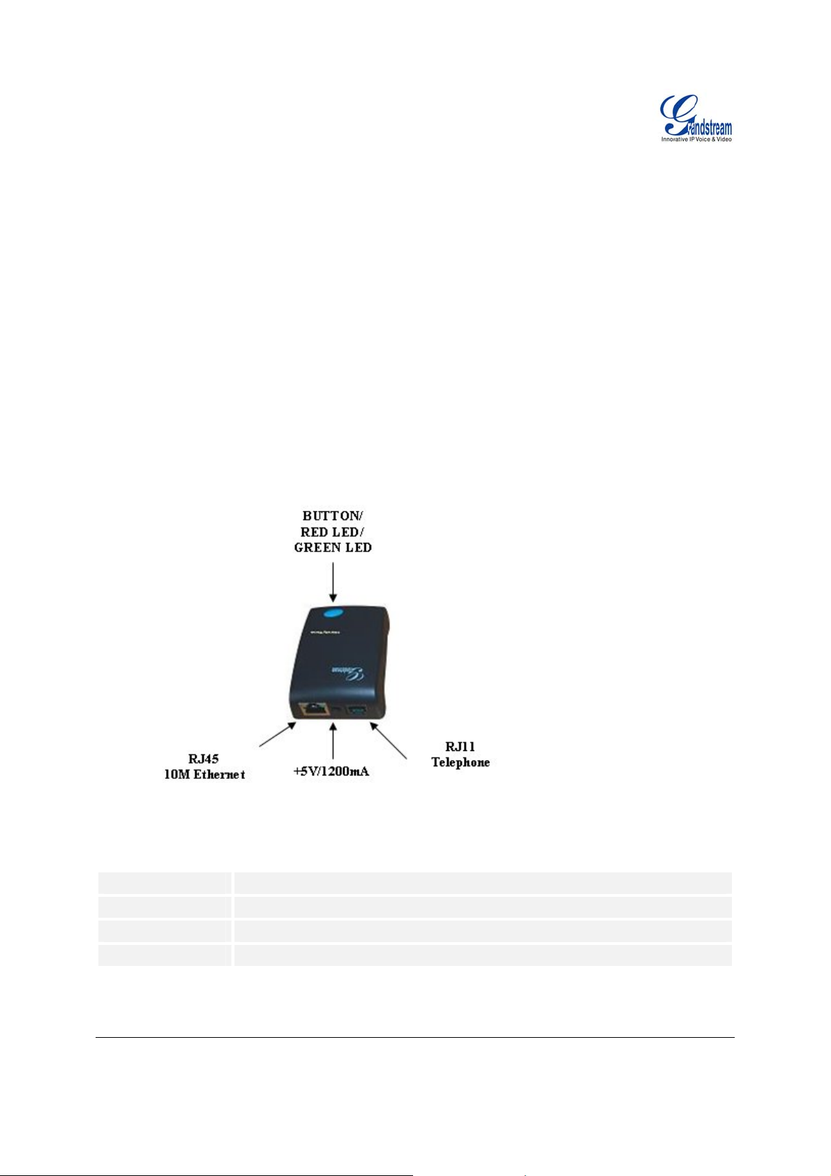
The HT–286 is easy to configure. HandyTone-286 is a VoIP Analog Telephone Adaptor designed to work
with an ordinary analog telephone. The following photo illustrates the appearance of a HandyTone-286.
F
IGURE 1: CONNECTING THE HT286
T
ABLE 1: DEFINITIONS OF THE HT–286 CONNECTORS
Power Cable
LAN Port (RJ-45)
PHONE
BUTTON
Grandstream Networks, Inc. HT–286 User Manual Page 5 of 28
Firmware 1.1.0.31 Last Updated: 1/2009
Power adapter connection
Connect the LAN port with an Ethernet cable to your PC.
FXS port to be connected to analog phones / fax machines.
Button and two colors led indicator.
Page 6
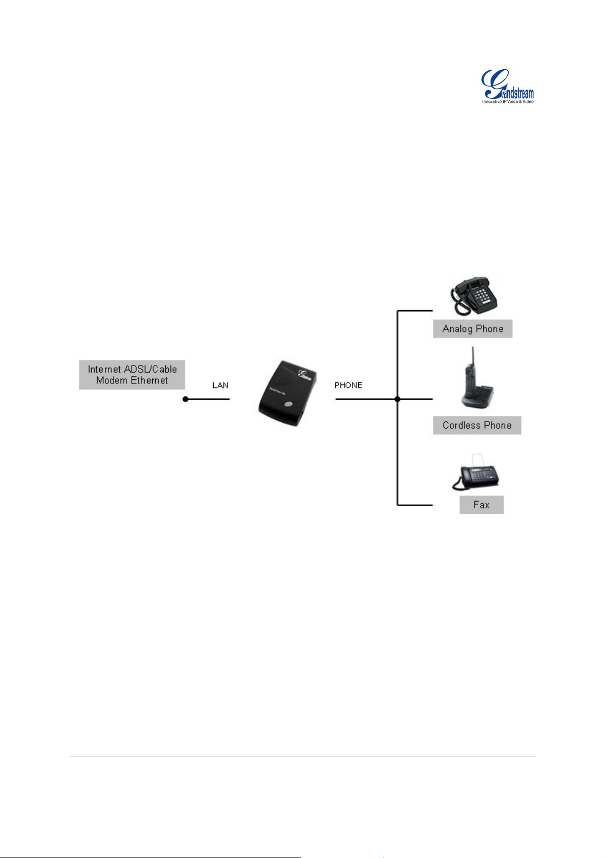
T
HREE EASY STEPS TO INSTALL THE HT–286
1. Connect a standard touch-tone analog telephone (or fax machine) to FXS port.
2. Insert the Ethernet cable into the LAN port of HT–286 and connect the other end of the Ethernet
cable to an uplink port (a router or a modem, etc.)
3. Insert the power adapter into the HT–286 and connect it to a wall outlet.
F
IGURE 2: HT286 CONNECTION DIAGRAM
Grandstream Networks, Inc. HT–286 User Manual Page 6 of 28
Firmware 1.1.0.31 Last Updated: 1/2009
Page 7

Product Overview
HT-286 supports one FXS port for Internet data, voice, and fax.
K
EY FEATURES
Ethernet
Ports
1 RJ45 (LAN) Client 1 No Yes
ABLE 2: HT–286 TECHNICAL SPECIFICATIONS
T
Lines/SIP Accounts
Protocol Support
Feature Keys
LAN Interface
Device Management
Support device configuration via built-in IVR, Web browser or central
Support Layer 2 (802.1Q, VLAN, 802.1p) and Layer 3 QoS (ToS, DiffServ,
Auto/manual provisioning system
NAT-friendly remote software upgrade (via TFTP/HTTP) for deployed devices
Syslog support (on Rev 2.0)
DHCP Server/Client Yes, Client
Audio Features
Call Handling
Features
Network and
DHCP
1 lines / 1 SIP accounts
SIP 2.0 (RFC 3261), TCP/UDP/IP, RTP/RTCP, HTTP, ARP/RARP, ICMP,
DNS, DHCP, NTP, TFTP, PPPoE protocols
1 button
RJ-45 10 Mbps
Web interface or via secure (AES encrypted) central configuration file for mass
deployment
configuration file through TFTP or HTTP
MPLS)
including behind firewall/NAT
Advanced Digital Signal Processing (DSP)
Dynamic negotiation of codec and voice payload length
Support for G.723,1 (5.3K/6.3K), G.729A, G.711 µ/A, G.726, and iLBC codecs
In-band and out-of-band DTMF (in audio, RFC2833, SIP INFO)
Silence Suppression, VAD (voice activity detection), CNG (comfort noise
generation), ANG (automatic gain control), Line Echo Cancellation( G.168)
Adaptive jitter buffer control
Packet delay & loss concealment
Support volume amplification
Support configurable Call Progress Tones
Caller ID display or block, Call waiting caller ID, Call waiting/Flash, Call
transfer, hold, forward, mute, 3-way conferencing(on Rev 2.0)
Manual or dynamic host configuration protocol (DHCP) network setup; RTP
FXS
Port
PSTN
Pass –
through
Voice Mail
Indicator
Voice Codec
iLBC, G.723,
G.711, G.729,
G.726, T.38
Remote
Configuration
TFTP/HTTP
Grandstream Networks, Inc. HT–286 User Manual Page 7 of 28
Firmware 1.1.0.31 Last Updated: 1/2009
Page 8

Provisioning
Fax over IP T.38 compliant Group 3 Fax Relay up to 14.4kpbs and auto-switch to G.711 for
Security
Physical Design
T
ABLE 3: HT–286 HARDWARE SPECIFICATIONS
LAN Interface
FXS phone port
Button
LED
Universal
Switching
Power Adaptor
Dimension
Weight
Temperature
Humidity
Compliance
and NAT support traversal via STUN
Fax Pass-through (pending), Fax Datapump V.17, V.19, V.27ter, V.29 for T.38
fax relay
DIGEST authentication and encryption using MD5 and MD5-sess
Stylish and compact design; small universal power supply, ideal for travel
1 x RJ45 10 Mbps
1 x FXS
1
Green and red / solid state & blinking state
Input: 100-240VAC 50-60 Hz
Output: +5VDC, 1200mA
UL certified
65mm (W) x 93mm (D) x 27mm (H)
0.57 lbs (0.26kg)
32 - 104oF / 0 - 40oC
10% - 90% (non-condensing)
FCC/CE/C-Tick
Grandstream Networks, Inc. HT–286 User Manual Page 8 of 28
Firmware 1.1.0.31 Last Updated: 1/2009
Page 9

Basic Operations
GET FAMILIAR WITH VOICE PROMPT
HT–286 stores a voice prompt menu (Interactive Voice Response or IVR) for quick browsing and simple
configuration.
Pick up the handset and press the button on the HT–286 or
T
ABLE 4: HT–286 IVR MENU DEFINITIONS
Menu Voice Prompt Options
dial “***” to use the IVR menu.
Main Menu
01
02
03
04
05
07
13
14
15
16
17
“Enter a Menu Option” Press “*” for the next menu option
Press “#” to return to the main menu
Enter 01-05, 07,12-17,47 or 99 menu options
“DHCP Mode”,
“Static IP Mode”
“IP Address “ + IP address The current WAN IP address is announce d
“Subnet “ + IP address Same as menu 02
“Gateway “ + IP address Same as menu 02
“DNS Server “ + IP address Same as menu 02
Preferred Vocoder
Firmware Server IP
Address
Configuration Server IP
Address
Upgrade Protocol
Firmware Version
Firmware Upgrade
Press “9” to toggle the selection
If using “Static IP Mode”, configure the IP address
information using menus 02 to 05.
If using “Dynamic IP Mode”, all IP address information
comes from the DHCP server automatically after reboot.
If using “Static IP Mode”, enter 12 digit new IP address.
Press “9” to move to the next selection in the list:
• PCM U
• PCM A
• G.723
• G.729
• iLBC
• G.726
Announces current Firmware Server IP address. Enter
12 digit new IP address.
Announces current Config Server Path IP address. Enter
12 digit new IP address.
Upgrade protocol for firmware and configuration update.
Press “9” to toggle between TFTP / HTTP
Firmware version information.
Firmware upgrade mode. Press “9” to toggle among the
following three options:
- always check
- check when pre/suffix changes
- never upgrade
Grandstream Networks, Inc. HT–286 User Manual Page 9 of 28
Firmware 1.1.0.31 Last Updated: 1/2009
Page 10

47
99
T
ABLE 5: IVR ERROR REPORT
IVR supports error reporting when the following problems occur. User will hear silence when picking
up the handset. After pressing ***, user will hear one or more error codes listed below. User may hear
one or more error codes depending on errors detected such as E104E103E. Upon hearing error code,
user can press # to get into the IVR main menu.
E101E
E102E
E103E
E104E
NOTE:
1. Once the button is pressed, it enters the voice prompt main menu. If the button is pressed again,
while it is already in the voice prompt menu, it jumps to “Direct IP Calling” option and a dial tone is
prompted
*” shifts down to the next menu option
2. “
“
#” returns to the main menu
“
9” functions as the ENTER key in many cases to confirm an option
3. All entered digit sequences have known lengths - 2 digits for menu option and 12 digits for IP address.
For IP address, add 0 before the digits if the digits are less than 3 (like 192.168.0.26 should be key in
like 192168000026, no dot needed while input). Once all of the digits are collected, the input will be
processed.
4. Key entry can not be deleted but the phone may prompt error once it is detected
“Direct IP Calling”
“RESET”
“Invalid Entry”
Enter a 12 digit IP address to make a direct IP call, after
dial tone. (See “Make a Direct IP Call”.)
Press “9” to reboot the device; or
Enter encoded MAC address to restore factory default
setting (See “Restoring Factory Settings”)
Automatically returns to main menu
Ethernet link down
No IP address obtained (DHCP or PPPoE mode)
Device is not registered to SIP server
No STUN responses
PLACING A PHONE CALL
PHONE OR EXTENSION NUMBERS
1. Dial the number directly and wait for 4 seconds (Default “No Key Entry Timeout”); or
2. Dial the number directly and press # (Use # as dial key” must be configured in web configuration).
Examples:
1. Dial an extension directly on the same proxy, (e.g. 1008), and then press the # or wait for 4 seconds.
2. Dial an outside number (e.g. (626) 666-7890), first enter the prefix number (usually 1+ or international
code) followed by the phone number. Press # or wait for 4 seconds. Check with your VoIP service
provider for further details on prefix numbers.
Grandstream Networks, Inc. HT–286 User Manual Page 10 of 28
Firmware 1.1.0.31 Last Updated: 1/2009
Page 11

IRECT IP CALLS
D
Direct IP calling allows two parties with VoIP devices (e.g. a HT–286and another VoIP Device), to talk to
each other in an ad hoc fashion without a SIP proxy. Direct IP calls are possible if:
a) Both VoIP devices use a public IP address; or
b) Both VoIP devices are on the same LAN using private IP addresses, or
c) Both VoIP devices can be connected through a router using public or private IP addresses (with
necessary port forwarding or DMZ).
To make a Direct IP Call, use either the handset or the speakerphone. Access the IVR using “***”, the
button on the HT–286or “47”. After dial tone, enter a 12-digit target IP address to place a call.
Destination ports can be specified by using “*4” (encoding for “:”) followed by the port number.
Examples:
a) If the target IP address is 192.168.0.160, enter the 12 digit IP address (e.g. 1921680160) after
the voice prompt followed by the “#” key or wait for 4 seconds. The default destination port 5060
is used if no port is specified.
b) If the target IP address/port is 192.168.1.20:5062
1921680160*45062) after the voice prompt followed by the “#” key or wait for 4 seconds.
, enter the 12 digit IP address + *45062 (e.g.
CALL HOLD
Press the “flash” button (or hook flash on older models) to place a caller on hold. Press the “flash” button
again to release call hold.
CALL WAITING
If call waiting feature is enabled, call waiting tone (3 short beeps) indicates an incoming call. Toggle
between incoming call and current call by pressing the “flash” button. First call is placed on hold. Press
the “flash” button to toggle between tw o act i ve c alls .
CALL TRANSFER
The HT–286 supports both blind and attended transfer:
1. Blind Transfer: Press “flash” button (or hook flash on older models), dial *87, then dial the
number to transfer call and press the “#” key (or wait 4 seconds) to complete transfer of active
call.
Expected outcomes:
a) A quick confirmation tone
successful. Hang up or place another call.
b) A quick busy tone
indicates the transfer failed.
c) Continuous busy tone
indicate the transfer has been successful, nor does it indicate the transfer has failed. It often
means there was a failure to receive second NOTIFY – check firmware for most recent release.
NOTE: “Enable Call Feature” must be set to “Yes” in web configuration page.
Grandstream Networks, Inc. HT–286 User Manual Page 11 of 28
Firmware 1.1.0.31 Last Updated: 1/2009
followed by a restored call (on supported platforms only). The busy tone
(call waiting tone) followed by a dial tone. This indicates the transfer is
. The phone call has timed out. Note: continuous busy tone does not
Page 12

2. Attended Transfer:
Assuming that call party A and B are in conversation. A wa nts to Attend Transfer B to C:
(1) A presses FLASH (on the analog phone, or Hook Flash for old model phones) to get a
dial tone
(2) A then dial C’s number then # (or wait for 4 seconds).
(3) If C answers the call, A and C are in conversation. Then A can hang up to complete
transfer.
(4) If C does not answer the call, A can press “flash” back to talk to B.
NOTE: If Attended Transfer fails, and party A hangs up, the HandTone-496 will ring party A to remind A
that party B is still on the line. Party A can pick up the phone to resume conversation with party B.
3-WAY CONFERENCING
HT–286 supports Star Code Style or Bellcore Style 3-way Conference.
Star Code Style 3-way Conference
Assuming that call party A and B are in conversation. A (HT-286) wants to bring C in a conference:
1. A presses FLASH (on the analog phone, or Hook Flash for old model phones) to get a dial tone.
2. A dials *23 then C’s number then # (or wait for 4 seconds).
3. If C answers the call, then A presses FLASH to bring B, C in the conference.
4. If C does not answer the call, A can press FLASH back to talk to B.
5. If A presses FLASH during conference, C will be dropped out.
Bellcore Style 3-way Conf erence
Bellcore style 3-way conference is also supported. To do this, user needs to enable “Use Bell-style 3-way
Conference” in ADVANCED SETTINGS web configuration.
Assuming that call party A and B are in conversation. A (HT-286) wants to bring C in a conference:
1. A presses FLASH (on the analog phone, or Hook Flash for old model phones) to get a dial tone.
2. A dials C’s number then # (or wait for 4 seconds).
3. If C answers the call, then A presses FLASH to bring B, C in the conference.
4. If C does not answer the call, A can press FLASH back to talk to B.
5. If A presses FLASH during conference, C will be dropped out.
Grandstream Networks, Inc. HT–286 User Manual Page 12 of 28
Firmware 1.1.0.31 Last Updated: 1/2009
Page 13

Call Features
The HT–286 supports all the traditional and advanced telephony features.
T
ABLE 6: HT–286 CALL FEATURE DEFINITIONS
Key Call Features
*23 3-way conference
*30
*31
*50
*51
*67
*70
*71
*72
*73
*82
*87 Blind Transfer
*90
*91
*92 Delayed Call Forward. Dial “*92”, wait for dial tone. Then dial the
*93
Flash/Hook
Block Caller ID (for all subsequent calls)
Send Caller ID (for all subsequent calls)
Disable Call Waiting (for all subsequent calls)
Enable Call Waiting (for all subsequent calls)
Block Caller ID (per call)
Disable Call Waiting (per call)
Enable Call Waiting (per call)
Unconditional Call Forward. Dial “*72”, wait for dial tone. Dial the
forward number and “#” for a dial tone, then hang up.
Cancel Unconditional Call Forward. To cancel “Unconditional Call
Forward”, dial “*73”, wait for dial tone, then hang up.
Send Caller ID (per call)
Busy Call Forward. Dial “*90” , wait for dial tone. Then dial the
forward number and “#” for a dial tone, then hang up.
Cancel Busy Call Forward. To cancel “Busy Call Forward”, dial “*91”,
wait for dial tone, then hang up.
forward number and “#” for a dial tone, then hang up.
Cancel Delayed Call Forward. To cancel Delayed Call Forward, dial
“*93”, wait for dial tone, then hang up.
Toggles between active call and incomin g call (call waiting tone). If not
in conversation, flash/hook will switch to a new channel for a new call.
T.38 Fax
HT–286 supports fax in two modes: 1) T.38 (Fax over IP) and 2) fax pass through.
T.38 is the preferred method b ec ause it is more reliable and works well in most network conditions. If the
service provider supports T.38, pl eas e use this method by selecting T.38 as fax mode
service provider does not support T.38, pass-through mode may be used.
(default). If the
LED Light Pattern Indication
Following tables show the LED light pattern indication.
Grandstream Networks, Inc. HT–286 User Manual Page 13 of 28
Firmware 1.1.0.31 Last Updated: 1/2009
Page 14

TABLE 7: HT–286 LED DEFINITIONS
RED LED indicates not normal status
Button flashes ev ery 1 seco n d
If Ethernet link is down
Button flashes ever y 2 secon ds.
DHCP Failed or WAN No Cable
(if DHCP is configured)
Button flashes ever y 4 secon ds.
HT–286 fails to register
(if SIP server is configured)
Button flashes ever y 6 secon ds.
Button flashe s bri e f l y
Firmware Upgrading
No STUN responses
Red light steady. Device Malfunctions
GREEN LED indicates normal status
Button flashes ever y 2 secon ds.
Button flashes at 1/10 second.
Button flashes every second.
Green light steady.
Message Waiting Indication
RINGING
RINGING INTERVAL
In Conversation
Grandstream Networks, Inc. HT–286 User Manual Page 14 of 28
Firmware 1.1.0.31 Last Updated: 1/2009
Page 15

Configuration Guide
CONFIGURING HT–286 THROUGH VOICE PROMPT
DHCP Mode
Select voice menu option 01 to enable HT–286 to use DHCP.
STATIC IP Mode
Select voice menu option 01 to enable HT–286 to use STATIC IP mode, then use option 02, 03, 04, 05 to
set up IP address, Subnet Mask, Gateway and DNS server respectively.
Firmware Server IP Address
Select voice menu option 13 to configure the IP address of the firmware server.
Configuration Server IP Address
Select voice menu option 14 to configure the IP address of the configuration server.
Upgrade Protocol
Select voice menu option 15 to choose firmware and configuration upgrade protocol. User can choose
between TFTP and HTTP.
Firmware Upgrade Mode
Select voice menu option 17 to choose firmware upgrade mode among the following three options:
1) always check, 2) check when pre/suffix changes, and 3) never upgrade
CONFIGURING HT–286 WITH WEB BROWSER
HT–286 has an embedded Web server that will respond to HTTP GET/POST requests. It also has
embedded HTML pages that allow users to configure the HT–286 through a Web browser such as
Microsoft’s IE and AOL’s Netscape.
A
CCESS THE WEB CONFIGURATION MENU
HandyTone-286 has embedded HTML pages that allows a user to configure the HandyTone-286 through
a Web browser.
1. Find the IP address of the HT–286 using voice prompt menu option 02.
2. Access the HT–286 Web Configuration page by the following URI via WAN port:
http://HandyTone-IP-Address
NOTE: If using a web browser to enter the configuration page, strip the leading “0”s because the browser
will parse in octet. (i.e. if the IP address is: 192.168.00
(the HandyTone-IP-Address is the IP address for the HT–286).
1.014, please type in: 192.168.1.14).
END USER CONFIGURATION
Once the HTTP request is entered and sent from a Web browser, the user will see a log in screen. There
are two default passwords for the login page:
User Level: Password: Web pages allowed:
End User Level 123 Only Status and Basic Settings
Administrator Level admin Browse all pages
Grandstream Networks, Inc. HT–286 User Manual Page 15 of 28
Firmware 1.1.0.31 Last Updated: 1/2009
Page 16

Only an administrator can access the “ADVANCED SETTING” configuration page.
NOTE: If you cannot log into the configuration page by using default password, please check with the
VoIP service provider. The service provider may have provisioned and configured the device for you. The
Basic Configuration Page is the first web GUI the user will see.
T
ABLE 8: HT–286 BASIC CONFIGURATION SETTINGS DEFINITIONS
End User Password
Web Port
IP Address
DHCP hostname
DHCP domain
DHCP vendor class ID
PPPoE account ID
Password to access the Web Configuration Menu. This field is case
sensitive with a maximum length of 25 chara c ters .
By default, HTTP uses port 80. This field is for customizable web port.
There are two modes to operate the HT–286:
DHCP mode: all the field values for the Static IP mode are not used (even
though they are still saved in the Flash memory.) The HT–286 acquires its
IP address from the first DHCP server it discovers from the LAN it is
connected.
Using the PPPoE feature: set the PPPoE account settings. The HT–286
will establish a PPPoE session if any of the PPPoE fields is set.
Static IP mode: configure the IP address, Subnet Mask, Default Router
IP address, DNS Server 1 (primary), DNS Server 2 (secondary) fields.
These fields are set to zero by default.
This option specifies the name of the client. This field is optional but may
be required by some Internet Service Providers. Default is blank.
This option specifies the domain name that client should use when
resolving hostnames via the Domain Name System. Default is blank.
Used by clients and servers to exchange vendor-specific information.
Default is blank.
PPPoE username. Necessary if ISP requires you to use a PPPoE (Point
to Point Protocol over Ethernet) connection.
PPPoE password
PPPoE Service Name
PPPoE account password.
This field is optional. If your ISP uses a service name for the PPPoE
connection, enter the service name here. Default is blank.
Time Zone
Controls how the date/time displays according to the specified time zone.
Grandstream Networks, Inc. HT–286 User Manual Page 16 of 28
Firmware 1.1.0.31 Last Updated: 1/2009
Page 17

Daylight Savings
Time
Controls whether displayed time is daylight savings time or not. If set to “Yes”
and the Optional Rule is empty, then the displayed time will be 1 hour ahead of
normal time.
• The “Automatic Daylight Saving Time Rule” has the following syntax:
o start-time;end-time;saving. Both start-time and end-time have
the same syntax: month,day,weekday,hour,minute
o month: 1,2,3,..,12 (for Jan, Feb, .., Dec)
o day: [+|-]1,2,3,..,31
o weekday: 1, 2, 3, .., 7 (for Mon, Tue, .., Sun), or 0 indicat ing
daylight savings rule is based on the day of the month.
o hour: hour (0-23),
o minute: minute (0-59)
• If “weekday” is 0, it means the date to start or end daylight savings is
the given date. The “day” value must not be negative.
• If “weekday” is not zero and “day” is positive, then daylight saving starts
on the first “day” of the week (1st Sunday, 3rd Tuesda y etc ).
• If “weekday” is not zero and “day” is negative, then daylight savings
starts on the last “day” of the week (last Sunday, 3rd last Tuesday etc).
• Daylight savings is in minutes. If preceded by a (-), then subtract the
number of minutes.
The default value for “Automatic Daylight Saving Time Rule” is US time:
“04,01,7,02,00;10,-1,7,02,00;60”.
Example: US/Canada, where daylight savings is applicable:
04,01,7,02,00;10,-1,7,02,00;60
Daylight savings starts from the first Sunday of April at 2AM and ends the last
Sunday of October at 2AM.).
In addition to the Basic Settings configuration page, end users also have access to the Device Status
page.
T
ABLE 9: HT–286 DEVICE STATUS PAGE DEFINITIONS
MAC Address
WAN IP Address
Product Model
Software Version
The device ID in HEX format. This is needed for ISP troubleshooting.
Shows WAN IP address of HT–286.
Contains the product model info.
Program: This is the main software release. Boot a nd Loader are seldom
changed.
System Up Time
Registered
Shows system up time since the last reboot.
Indicates whether the HT–286 is registered to the service provider’s
server.
PPPoE Link Up
Indicates whether the PPPoE connection is up if the HT–286 is connected
to DSL modem.
NAT
Indicates the type of NAT the HT–286 is connec te d to v ia its W AN port.
Based on STUN protocol.
Grandstream Networks, Inc. HT–286 User Manual Page 17 of 28
Firmware 1.1.0.31 Last Updated: 1/2009
Page 18

NAT Mapped IP
NAT Mapped Port
Statistical Status
WAN side mapped IP if HandyTone-286 is connected to a NAT router.
WAN side mapped port if HandyTone-286 is connected to a NAT router.
Self-explainable. Please refer to the page displayed.
DVANCED USER CONFIGURATION
A
Log in to the advanced user configuration page the same way as for the basic configuration page. The
password is case sensitive and the factory default password for Advanced User is “admin”.
Advanced User configuration includes the end user configuration and the advanced configurations
including: a) SIP configuration, b) Codec selection, c) NAT Traversal Setting and d) other miscellaneous
configuration.
T
ABLE 10: HT–286 ADVANCED CONFIGURATION PAGE DEFINITIONS
Admin Password
Administrator password. Only administrator can configure the “Advanced
Settings” page. Password field is purposely left blank for security reason after
clicking update and saved. The maximum password length is 25 characters.
SIP Server
This field contains the URI string or the IP address. e.g. sip.my-voipprovider.com; 192.168.1. 2 0 0 :5 066
Outbound Proxy
SIP User ID
Authenticate ID
Authenticate
Password
Name
Home NPA
Preferred Vocoder
G723 Rate:
This field contains the URI string or the IP of the outbound proxy. If there is
no outbound proxy, this field SHOULD be left blank. If it is not blank, all
outgoing requests will be sent to this outbound proxy.
This field contains the user part of the SIP address for this phone. e.g., if the
SIP address is: sip:my_user_id@my_provider.com, then the SIP User ID is:
my_user_id. Please do NOT include the preceding “sip:” scheme or the host
portion of the SIP address in this field. It is given by VoIP service provider.
SIP service subscriber’s Authenticate ID used for authentication. It can be
identical to or different from SIP User ID and given by VoIP service provider.
SIP service subscriber’s account password. It is given by VoIP service
provider.
SIP service subscriber’s name which will be used for Caller ID display.
Local area code for North American Dial Plan.
HandyTone-286 supports up to 7 different vocoder types including G711-
ulaw (PCMU), G711-alaw (PCMA), G723, G729A, G726-32, and iLBC.
Depending on the product model, some of these vocoders may not be
provided in standard release.
A user can configure vocoders in a preference order that will be offered in
SIP INVITE message.
This defines the encoding rate for G723 vocoder. By default, 6.3kbps rate is
chosen.
Grandstream Networks, Inc. HT–286 User Manual Page 18 of 28
Firmware 1.1.0.31 Last Updated: 1/2009
Page 19

iLBC frame size
iLBC payload type
Silence Suppression
Voice Frames per TX
This defines the size of the iLBC codec frame. The defau lt s et ting is 20ms.
This defines the iLBC payload type. The default setting is 97. The valid
range is between 96 and 127.
This controls the silence suppression/VAD feature of G723 and G729. If set
to “Yes”, when a silence is detected, small quantity of VAD packets (instead
of audio packets) will be sent during the period of no talking. If set to “No”,
this feature is disabled.
This field contains the number of voice frames to be transmitted in a single
packet. When setting this value, the user should be aware of the requested
packet time (used in SDP message) as a result of configuring this parameter.
This parameter is associated with the first vocoder in the above vocoder
Preference List or the actual used payload type negotiated between the 2
conversation parties at run time.
e.g., if the first vocoder is configured as G723 and the “Voice Frames per TX”
is set to be 2, then the “ptime” value in the SDP message of an INVITE
request will be 60ms because each G723 voice frame contains 30ms of
audio. Similarly, if this field is set to be 2 and if the first vocoder chosen is
G729 or G711 or G726, then the “ptime” value in the SDP message of an
INVITE request will be 20ms.
If the configured voice frames per TX exceeds the maximum allowed value,
the phone will use and save the maximum allowed value for the
corresponding first vocoder choice. The maximum value for PCM is
10(x10ms) frames; for G726, it is 20 (x10ms) frames; for G723, it is 32
(x30ms) frames; for G729/G728, 64 (x10ms) and 64 (x2.5ms) frames
respectively.
Fax Mode
Layer 3 QoS
Layer 2 QoS
Allow incoming SIP
messages from SIP
proxy only
Use DNS SRV
User ID is phone
number
SIP Registration
Unregister On Reboot
T.38 (Auto Detect) FoIP by default, or Pass-Through (must use codec
PCMU/PCMA)
This field defines the layer 3 QoS parameter which can be the value used for
IP Precedence or Diff-Serv. Def au lt value is 48
This setting includes two fields. The 802.1Q/VLAN Tag contains the value
used for layer 2 VLAN tag. Default setting is blank. And 802.1p priority value
contains the value of the priority value.
If set to “Yes”, the device will ignore any SIP message that does not come
from the IP address (Source IP in the IP header) that it is registered
to. Default is No.
This parameter controls whether the IP phone supports the DNS SRV route
function.
If the HandyTone-286 has an assigned PSTN telephone number, then this
field will be set to “Yes”. Otherwise, set it to “No”. If “Yes” is set, a
“user=phone” parameter will be attached to the “From” header in SIP request.
This parameter controls whether the IP phone needs to send REGISTER
messages to the proxy server. The default setting is “Yes”.
Default is No. If set to yes, the device will first send registration request to
remove previous bindings.
Grandstream Networks, Inc. HT–286 User Manual Page 19 of 28
Firmware 1.1.0.31 Last Updated: 1/2009
Page 20

Registration
Expiration
Early Dial
Allow outgoing call
without Registration
Dial Plan Prefix
No Key Entry
Timeout
Use # as
Send Key
This parameter allows the user to specify the time frequency (in minutes) the
phone will refresh its registration with the specified registrar. The default
interval is 3600 seconds (or 1 hour). The maximum interval is 45 days.
This parameter controls whether the phone will attempt to send an early
INVITE each time a key is pressed when a user dials a number. If set to
“Yes”, an INVITE is sent using the dial-number collected thus far; Otherwise,
no INVITE is sent until the “(Re-)Dial” button is pressed or after about 5
seconds have elapsed if the us er forgets to press the “(Re-)Dial” button.
The “Yes” option should be used ONLY if there is a SIP proxy configured and
the proxy server supports 484 Incomplete Address response. Otherwise, the
call will most likely be rejected by the proxy (with a 404 Not Found error).
Please note that this feature is NOT designed to work with and should NOT
be enabled for direct IP-to-IP calling.
Default is set to “No”.
This value contains the dial plan prefix string (typically an ASCII numeric
string). If it is not blank, then this string will added to the dialed number.
Default is 4 seconds.
This parameter allows the user to configure the “#” key to be used as the
“Send”(or “Dial”) key. Once set to “Yes”, pressing this key will immediately
trigger the sending of dialed string collected so far. In this case, this key is
essentially equivalent to the “(Re)Dial” key. If set to “No”, this # key will then
be included as part of the dial string to be sent out.
Local SIP port
Local RTP port
Use Random Port
SIP Registration
Failure Retry Wait
Time
This parameter defines the local SIP port the IP phone will listen and transmit
on. The default value is 5060.
This parameter defines the local RTP-RTCP port pair the IP phone will listen
and transmit on. It is the base RTP port for channel 0. When configured,
channel 0 will use this port value for RTP and the port_value+1 for its RTCP;
channel 1 will use port_value+2 for RTP and port_value+3 for its RTCP. The
default value is 5004.
This parameter, when set to Yes, will force random generation of both the
local SIP and RTP ports. This is usually necessary when multiple IP phones
are behind the same NAT.
Retry registration if the process failed. Default is 20 seconds.
Grandstream Networks, Inc. HT–286 User Manual Page 20 of 28
Firmware 1.1.0.31 Last Updated: 1/2009
Page 21

NAT Traversal
keep-alive interval
Use NAT IP
Use STUN keep-alive
to detect networks
connectivity
Proxy-Require
SUBSCRIBE for MWI
Off hook
Auto-Dial
This parameter defines whether the phone NAT traversal mechanism will be
activated or not. If activated (by choosing “Yes”) and a STUN server is also
specified, then the phone will behave according to the STUN client
specification. Under this mode, the embedded STUN client inside the phone
will attempt to detect if and what type of firewall/NAT it is behind by sending
appropriate request to the specified STUN server.
If this field is set to “Yes” with no specified STUN server, then the phone will
only periodically (every 20 seconds by default) send a blank UDP packet
(with no payload data) to the SIP server to keep the mapped port open on the
NAT.
The HandyTone-286 sends a UDP package to the SIP server periodically in
order to keep the port open on the router. This parameter defines the interval
time that HT286 send the UDP package. The default setting is 20 second.
NAT IP address is used in SIP/SDP message. Default is blank.
Use STUN keep-alive to detect WAN side network problems. If keep-alive request
does not yield any response for configured number of times, the device will restart the
TCP/IP stack. If the STUN server does not respond when the device boots up, the
feature is disabled.
SIP Extension to notify SIP server that the unit is behind the NAT/Firewall.
Default is “No”. When set to “Yes” a SUBSCRIBE for Message Waiting
Indication will be sent periodically
This parameter allows the user to configure a User ID or extension number to
be automatically dialed upon off hook. Please note that only the user part of a
SIP address needs to be entered here. The phone will automatically append
the “@” and the host portion of the corresponding SIP address.
Enable Call Feature
Default is Yes. If set to “Yes”, call features using star codes are supported
locally.
Use Bell-style 3-way
conference
Disable Call Waiting
Disable Call-Waiting
Conference mode, default option is No. If set to yes, the feature code for
coference *23 would be disabled.
Default is No.
Default is No.
Caller-ID
Send DTMF
This parameter specifies the mechanism to transmit DTMF digit. There are 3
modes supported: in audio which means DTMF is combined in audio signal
(not very reliable with low-bit-rate codec), via RTP (RFC2833), or via SIP
INFO.
DTMF Payload Type
Send Flash Event
Onhook Threshold
This parameter sets the payload type for DTMF using RFC2833
Default is No. If set to yes, flash will be sent as DTMF event.
The amount of time the hookflash is pressed that will cause the device to on
hook. Default is 800ms.
FXS Impedance
Grandstream Networks, Inc. HT–286 User Manual Page 21 of 28
Firmware 1.1.0.31 Last Updated: 1/2009
Selects the impedance of the analog telephone connected to the Phone port.
Page 22

Caller ID Scheme
Onhook Voltage
Polarity Reversal
NTP server
Send Anonymous
Anonymous Method
Select the Caller ID Scheme to suit the standard of differen t area.
• Bellcore (North America)
• CID (Canada)
• DTMF (Brazil)
• DTMF (Denmark)
• DTMF (Sweden)
• ETSI-FSK (France, Germany, Norway, Taiwan, UK-CCA)
• ETSI-DTMF (Finland, Sweden)
The onhook voltage can be selected according to the line voltage depen ding
on the analog phone used. The low power/high power will increase/decrease
the output current. Selecting "low power" will make loop current limit = 20mA,
selecting "high power" make loop current limit = 32mA. The default selection
is 36V (High Power).
Select Polarity Reversal to adapt some call charge/billing system. Default is
No.
This parameter defines the URI or IP address of the NTP server which the IP
phone will use to display the current date/time.
If this parameter is set to “Yes”, the device is employing the mechanism to
block its ID.
If it is set to “Use from header”. Callers’ SIP user ID will be sent as
anonymous, essentially bl ock the Caller ID from displaying. If it is set to “User
privacy header”, the SIP INVITE message contains a “privacy” header, and
the server blocks the caller ID from the called party.
Time to ring
Special Features
CBCOM Encode
CBCOM Encoder 1.1
Key:
Syslog Server
This setting allows user to adjust the ring time of the phone. Default is 60
seconds.
Default is Standard. Choose the selection to meet some special requirements
from Soft Switch vendors like Nortel, Broadsoft, CBCOM etc.
SIP, RT(C)P and T.38 modes, 1.0 and 1.1
Key to be used by CBCOM
The IP address or URL of System log server. This feature is especially useful
for ITSP (Internet Telephone Service Provider)
Grandstream Networks, Inc. HT–286 User Manual Page 22 of 28
Firmware 1.1.0.31 Last Updated: 1/2009
Page 23

Syslog Level
Session Expiration
Select the ATA to report the log level. Default is NONE. The level is one of
DEBUG, INFO, WARNING or ERROR. Syslog messages are sent based on
the following events:
• product model/version on boot up (INFO level)
• NAT related info (INFO level)
• sent or received SIP message (DEBUG level)
• SIP message summary (INFO level)
• inbound and outbound calls (INFO level)
• registration status c hange (INFO level)
• negotiated codec (INFO level)
• Ethernet link up (INFO level)
• SLIC chip exception (WARNING and ERROR levels)
• memory exception (ERROR level)
The Syslog uses USER facility. In addition to standard Syslog payload, it
contains the following components:
GS_LOG: [device MAC address][error code] error message
Here is an example: May 19 02:40:38 192.168.1.14 GS_LOG:
[00:0b:82:00:a1:be][000] Ethernet link is up
Grandstream implemented SIP Session Timer. The session timer extension
enables SIP sessions to be periodically “refreshed” via a re-INVITE request.
Once the session interval expires, if there is no refresh via a re-INVITE
message, the session will be terminated.
Session Expiration is the time (in seconds) at which the session is considered
timed out, if no successful session refresh transaction occurs beforehand.
The default value is 180 seconds.
Min-SE
The minimum session expiration (in seconds). The default value is 90
seconds.
Caller Request Timer
If selecting “Yes” the phone will use session timer when it makes outbound
calls if remote party supports session timer.
Callee Request Timer
If selecting “Yes” the phone will use session timer when it receives inbound
calls with session timer request.
Force Timer
If selecting “Yes” the phone will use session timer even if the remote party
does not support this feature. Selecting “No” will allow the phone to enable
session timer only when the remote party support this feature.
To turn off Session Timer, select “No” for Caller Request Timer, Callee
Request Timer, and Force Timer.
UAC Specify
Refresher
UAS Specify
Refresher
Force INVITE
As a Caller, select UAC to use the phone as the refresher, or UAS to use the
Callee or proxy server as the refresher.
As a Callee, select UAC to use caller or proxy server as the refresher, or
UAS to use the phone as the refresher.
Session Timer can be refreshed using INVITE method or UPDATE method.
Select “Yes” to use INVITE method to refresh the session timer.
Grandstream Networks, Inc. HT–286 User Manual Page 23 of 28
Firmware 1.1.0.31 Last Updated: 1/2009
Page 24

Firmware Upgrade
and Provisioning
Firmware Server Path
Config Server Path
Firmware File Prefix
Firmware File Postfix
Config File Prefix
Config File Postfix
Automatic Upgrade
Firmware Key
Authenticate Conf
File
Default HTTP. Firmware upgrading may take up to 10 minutes depends on
network environment. Do not interrupt the firmware upgrading process.
IP address or domain name of firmware server.
IP address or domain name of configuration server
Default blank. If it is configured, HT286 rev. 3.0 will request the firmware file
with the prefix. Useful for ITSPs. End user should keep it blank.
Default is blank. End user should keep it blank.
Default is blank. End user should keep it blank.
Default is blank. End user should keep it blank.
Choose “Yes” to enable automatic upgrade and provisioning and input the
number, in minutes, you want the HT to check for an update. When set to No,
HT286 will only do upgrade once at boot up. “Always check for New
Firmware at Boot up” will check for new firmware every time the device
reboots. “Check New Firmware only when F/W pre/suffix changes” will check
for updates only when the pre/suffix has been changed.
32 digit in Hexadecimal Representation. Useful for ITSP to encrypt firmware.
End user should keep it blank.
Default No. End user should use default setting.
Lock keypad update
If this parameter is set to “Yes”, except for IVR MENU items 1 to 5, the
configuration update via keypad is disabled.
Allow conf SIP
Account
If set to Yes, these four fields: SIP User ID, Authenticate ID, Authenticate
Password and Name will be included in Basic Settings configuration page.
in Basic Settings
Override MTU size Override the MTU size.
Volume Amplification
Handset volume adjustment. RX is for receiving volume, TX is for
transmission volume. Default values are 0dB for both parameters. +6dB
generates the highest volume and -6dB generates the lowest volume.
Powerline Ring Tone
Call Progress Tones
This setting allows user to configure the ringing frequencies and cadences.
Using these settings, users can configure various call progress tone
frequencies and cadences according to their country standard. By default
they are set to North American standard.
Frequencies should be configured with known v alues to avoid uncomfortable
high pitch sounds. ON is the period of ringing (“On time” in ‘ms’) while OFF is
the period of silence. In order to set a continuous ring, OFF should be zero.
Otherwise it will ring ON ms and a pause of OFF ms and then repeat the
pattern. Up to three cadences are supported.
Disable Line Echo
Default is No. If set to Yes, echo canceller is not used.
Canceller (LEC):
Grandstream Networks, Inc. HT–286 User Manual Page 24 of 28
Firmware 1.1.0.31 Last Updated: 1/2009
Page 25

S
AVING THE CONFIGURATION CHANGES
After making a change, click the “Update” button in the Configuration page. The HT–286 will display a
screen to confirming changes. Reboot or power cycle the HT–286 to enable the changes.
REBOOTING THE HT–286 FROM REMOTE
The administrator of the HT–286 can remotely reboot the HT–286 by clicking the “Reboot” button at the
bottom of the configuration page. When finished, re-login to the HT–286 after waiting about 30 seconds.
CONFIGURATION THROUGH A CENTRAL SERVER
Grandstream HandyTone ATA can be automatically configured from a central provisioning system.
When HandyTone ATA boot up, it will send TFTP or HTTP request to download configuration file
“cfg000b82xxxxxx”, where “000b82xxxxxx” is the MAC address of the HandyTone ATA. The configuration
file can be loaded into devices v ia TFTP or HTTP from the central provisi on ing server, so the service
provider or an enterprise with large deployment of HandyTone ATAs can easily manage the configuration
and service provision to individual devices remotely.
Grandstream has a provisioning system called GAPS (Grandstream Automated Provisioning System) that
is used to support automated configuration of Grandstream devices. GAPS uses enhanced (NAT friendly)
TFTP or HTTP (thus no NAT issues) and other communication protocols to communicate with each
individual Grandstream device for firmware upgrade, remote reboot, etc.
Grandstream provides GAPS service to VoIP service providers. Use GAPS fo r either simple redirection
or with certain special provisioning settings. At boot-up, Grandstream devices by default point to
Grandstream provisioning server GAPS, based on the unique MAC address of each device, GAPS
provision the devices with redirection settings so that they will be redirected to customer’s TFTP or
HTTP/HTTPS server for further provisioning. Grandstream also provide GAPSLite software package
which contains our NAT friendly TFTP server and a configuration tool to facilitate the task of generating
device configuration files.
The GAPSLite configuration tool is now free to end users. The tool and configuration template are
available for download from http://www.grandstream.com/configurationtool.html
Grandstream Networks, Inc. HT–286 User Manual Page 25 of 28
Firmware 1.1.0.31 Last Updated: 1/2009
Page 26

Software Upgrade
Software upgrade can be done via either TFTP o r HTTP. The corresponding configuration se ttings are in
the ADVANCED SETTINGS configuration page.
FIRMWARE UPGRADE THROUGH TFTP/HTTP
To upgrade via TFTP or HTTP, the “Firmware Upgrade an d Provisioning upgrade via” field needs to be
set to TFTP or HTTP, respectively. “Firmware Server Pa th” needs to be set to a valid URL of a TFTP or
HTTP server, server name can be in either FQDN or IP a ddress forma t. Here are examples of some valid
URL.
e.g. firmware.mycompany.com:6688/Grandstream/1.1.0.31
e.g. 168.75.215.189
NOTES:
• Firmware upgrade server in IP address format can be configured via IVR. Please refer to the
CONFIGURATION GUIDE section for instructions. If the server is in FQDN format, it must be set
via the web configuration interface.
• Grandstream recommends end-user use the Grandstream TFTP server. Its address can be found
at
http://www.grandstream.com/firmware.html. Currently the TFTP firmware server IP
address is 168.75.215.189. For large companies, we recommend to maintain their own TFTP/
HTTP/HTTPS server for upgrade and provisioning procedures.
• Once a “Firmware Server Path” is set, user nee ds to u pdate the s ettings a nd r ebo ot th e de vice. I f
the configured firmware server is found and a new code image is available, the HT ATA will
attempt to retrieve the new image files by d ownloading them into the HT ATA’s SRAM. During
this stage, the HT ATA’s LEDs will blink until the checking/downloading process is completed.
Upon verification of checksum, the new code image will then be saved into the Flash. If
TFTP/HTTP fails for any reason (e.g., TFTP/HTTP server is not responding, t here are no code
image files available for upgrade, or checksum test fails, etc), the HT ATA will stop the
TFTP/HTTP process and simply boot using the existing code image in the flash.
• Firmware upgrade may take as long as 1 to 20 minutes over Internet, or just 20+ seconds if it is
performed on a LAN. It is recommended to conduct firmware upgrade in a controlled LAN
environment if possible. For users who do not have a local firmware upgrade server,
Grandstream provides a NAT-friendly TFTP server on the public Internet for firmware upgrade.
Please check the Services section of Grandstream’s Web site to obtain our public TFTP server’s
IP address.
• Grandstream’s latest firmware is available
Oversea users are strongly recommended to download the binary files and upgrade firmware
locally in a controlled LAN environment.
• Alternatively, user can download a free TFTP or HTTP server and conduct local firmware
upgrade. A free windows version TFTP server is available for download from
http://support.solarwinds.net/updates/New-customerFree.cfm
Instructions to download a free TFTP Server
1. Unzip the file and put all of them under the root directory of the TFTP server.
2. Put the PC running the TFTP server and the HT286 device in the same LAN segment.
3. Please go to File -> Configure -> Security to change the TFTP server's default setting from
"Receive Only" to "Transmit Only" for the firmware upgrade.
4. Start the TFTP server, in the phone’s web configuration page
5. Configure the Firmware Server Path with the IP address of the PC
6. Update the change and reboot the unit
http://www.grandstream.com/firmware.html.
.
:
Grandstream Networks, Inc. HT–286 User Manual Page 26 of 28
Firmware 1.1.0.31 Last Updated: 1/2009
Page 27

End users can also choose to download the free HTTP server from http://httpd.apache.org/ or use
Microsoft IIS web server.
CONFIGURATION FILE DOWNLOAD
Grandstream SIP Device can be configured via Web Interface as well as via Configuration File through
TFTP or HTTP. “Config Server Path” is the TFTP or HTTP server path for configuration file. It ne eds to be
set to a valid URL, either in FQDN or IP address format. The “Config Server Path” can be same or
different from the “Firmware Server Path”.
A configuration parameter is associated with each particular field in the web configuration page. A
parameter consists of a Capital letter P and 2 to 3 (Could be extended to 4 in the future) digit numeric
numbers. i.e., P2 is associated with “Admin Password” in the ADVANCED SETTINGS page. For a
detailed parameter list, please refer to the corresponding firmware release configuration template.
When Grandstream Device boots up or reboots, it will issue request for configuration file named
“cfgxxxxxxxxxxxx”, where “xxxxxxxxxxxx” is the MAC address of the device, i.e., “cfg000b820102ab”. The
configuration file name should be in lower cases.
FIRMWARE AND CONFIGURATION FILE PREFIX AND POSTFIX
Firmware Prefix and Postfix allows device to download the firmware name with the matching Prefix and
Postfix. This makes it the possible to store ALL of the firmware with different version in one single
directory. Similarly, Config File Prefix and Postfix allows device to download the configuration file with the
matching Prefix and Postfix. Thus multiple configuration files for the same device can be stored in one
directory.
In addition, when the field “Check New Firmware only when F/W pre/suffix changes” is set to “Yes”, the
device will only issue firmware upgrade request if there are cha nges in the firmware Prefix or Postfix .
M
ANAGING FIRMWARE AND CONFIGURATION FILE DOWNLOAD
When “Automatic Upgrade” is set to “Yes”, Service Provider can use P193 (Auto Check Interval, in
minutes, default and minimum is 60 minutes) to have the devices periodically check with either Firmware
Server or Config Server, whenever they are defined. This allows the device periodically check if there are
any new changes need to be taken on a scheduled time. By defining different intervals in P193 for
different devices, Server Provider can spread the Firmware or Configuration File download in minutes to
reduce the Firmware or Provisioning Server load at any given time.
Grandstream Networks, Inc. HT–286 User Manual Page 27 of 28
Firmware 1.1.0.31 Last Updated: 1/2009
Page 28

Restore Factory Default Setting
WARNING! Restoring the Factory Default Setting will DELETE all conf iguration information of the
phone. Please BACKUP or PRINT out all the settings before you approach to following steps.
Grandstream will not take any responsibility if you lose all the parameters of setting and cannot
connect to your VoIP service provider.
Step 1:
Find the MAC Address of the device. It is a 12 digits HEX number located on the bottom of the
unit.
Step 2:
Encode the MAC address. Please use the following mapping:
0-9: 0-9
A: 22
B: 222
C: 2222
D: 33
E: 333
F: 3333
For example, if the MAC address is 000b8200e395, it should be encoded as
“0002228200333395”.
Step 3:
To perform factory reset:
- Pick up the headset. Dial “***” or press the LED button for voice prompt.
- Enter “99” and get the voice prompt “Reset”.
- Enter the encoded MAC address of the device.
- Wait for 15 seconds. The device will reboot automatically and restore to factory default setting.
NOTE: Factory Reset will be disabled if the “Lock keypad update” is set to “Yes”.
Grandstream Networks, Inc. HT–286 User Manual Page 28 of 28
Firmware 1.1.0.31 Last Updated: 1/2009
 Loading...