

Page 1

Grandstream Networks, Inc.
GDS3710
Hemispheric HD IP Video Door System
User Manual
Page 2

GDS3710 User Manual
Version 1.0.7.23
COPYRIGHT
©2021 Grandstream Networks, Inc. http://www.grandstream.com
All rights reserved. Information in this document is subject to change without notice. Reproduction or
transmittal of the entire or any part, in any form or by any means, electronic or print, for any purpose without
the express written permission of Grandstream Networks, Inc. is not permitted.
The latest electronic version of this user manual is available for download here:
http://www.grandstream.com/support
Grandstream is a registered trademark and Grandstream logo is trademark of Grandstream Networks, Inc.
in the United States, Europe and other countries.
CAUTION
Changes or modifications to this product not expressly approved by Grandstream, or operation of this
product in any way other than as detailed by this User Manual, could void your manufacturer warranty.
WARNING
Please do not use a different power adaptor with your devices as it may cause damage to the products and
void the manufacturer warranty.
P a g e | 2
Page 3

GDS3710 User Manual
Version 1.0.7.23
FCC Compliance Statement
This device complies with part 15 of the FCC Rules. Operation is subject to the following two conditions:
(1) The device may not cause harmful interference, and (2) This device must accept any interference
received, including interference that may cause undesired operation.
Important: Any changes or modification not expressly approved by the party responsible for compliance
could void the user’s authority to operate the equipment.
Note: This equipment has been tested and found to comply with limits for a Class B digital device, pursuant
to Part 15 of the FCC Rules.
These limits are designed to provide reasonable protection against harmful interference in a residential
installation. This equipment generates, uses and can radiate radio frequency energy and, if not installed
and used in accordance with instructions, may cause harmful interference to radio communications.
However, there is no guarantee that interference will not occur in a particular installation.
If this equipment does cause harmful interference to radio or television reception, which can be determined
by turning the equipment off and on, the user is encouraged to try to correct the interference by one or more
of the following measures:
• Reorient or relocate the receiving antenna.
• Increase the separation between the equipment and receiver.
• Connect the equipment into an outlet on a circuit different from that to which the receiver is
connected.
• Consult the dealer or an experienced radio/TV technician for help.
P a g e | 3
Page 4

GDS3710 User Manual
Version 1.0.7.23
CE Declaration of Conformity
This transmitter complies with the essential requirements and provisions of directives 2014/53/EU,
2014/30/EU, 2015/35/EU and subsequent amendments, according to standards
ETSI EN 300 330 V2.1.1 (2017-02);
ETSI EN 301 489-1 V2.1.1 (2017-02); ETSI EN 301 489-3 V2.1.1 (2017-03);
EN 60950-1: 2006+A11:2009+A1:2010+A12:2011+A2:2013: EN 62311: 2008
Manufacturer:
Grandstream Networks, Inc.
126 Brookline Ave, 3
Channel Frequency: 125 KHz
Channel Number: 1
Antenna Type / Gain: Internal
Type of Modulation: ASK
Operation temperature: -30 °C ~ +60 °C
Storage temperature: -35 °C ~ +60 °C
Humidity: 10 ~ 90% non-condensing
rd
Floor Boston, MA 02215, USA
P a g e | 4
Page 5

GDS3710 User Manual
Version 1.0.7.23
GNU GPL INFORMATION
GDS3710 firmware contains third-party software licensed under the GNU General Public License (GPL).
Grandstream uses software under the specific terms of the GPL. Please see the GNU General Public
License (GPL) for the exact terms and conditions of the license.
Grandstream GNU GPL related source code can be downloaded from Grandstream web site from:
http://www.grandstream.com/support/faq/gnu-general-public-license/gnu-gpl-information-download
P a g e | 5
Page 6

GDS3710 User Manual
Version 1.0.7.23
Table of Contents
DOCUMENT PURPOSE ............................................................................................... 15
CHANGE LOG .............................................................................................................. 16
Firmware Version 1.0.7.23 .............................................................................................................. 16
Firmware Version 1.0.7.19 .............................................................................................................. 16
Firmware Version 1.0.7.14 .............................................................................................................. 16
Firmware Version 1.0.7.11 .............................................................................................................. 16
Firmware Version 1.0.7.10 .............................................................................................................. 17
Firmware Version 1.0.7.8 ................................................................................................................ 17
Firmware Version 1.0.7.7 ................................................................................................................ 17
Firmware Version 1.0.7.4 ................................................................................................................ 17
Firmware Version 1.0.5.6 ................................................................................................................ 17
Firmware Version 1.0.5.2 ................................................................................................................ 18
Firmware Version 1.0.4.9 ................................................................................................................ 18
Firmware Version 1.0.3.35 .............................................................................................................. 19
Firmware Version 1.0.3.34 .............................................................................................................. 19
Firmware Version 1.0.3.32 .............................................................................................................. 19
Firmware Version 1.0.3.31 .............................................................................................................. 19
Firmware Version 1.0.3.23 .............................................................................................................. 19
Firmware Version 1.0.3.13 .............................................................................................................. 19
Firmware Version 1.0.2.25 .............................................................................................................. 20
Firmware Version 1.0.2.22 .............................................................................................................. 20
Firmware Version 1.0.2.21 .............................................................................................................. 20
Firmware Version 1.0.2.13 .............................................................................................................. 21
Firmware Version 1.0.2.9 ................................................................................................................ 21
Firmware Version 1.0.2.5 ................................................................................................................ 21
Firmware Version 1.0.1.19 .............................................................................................................. 22
WELCOME ................................................................................................................... 23
P a g e | 6
Page 7

GDS3710 User Manual
Version 1.0.7.23
PRODUCT OVERVIEW ................................................................................................ 24
Feature Highlights ................................ .......................................................................................... 24
Technical Specifications .................................................................................................................. 24
GETTING STARTED ..................................................................................................... 27
Equipment Packaging ..................................................................................................................... 27
Description of the GDS3710 ........................................................................................................... 28
Connecting and Setting up the GDS3710 ........................................................................................ 28
GDS3710 Wiring Connection .......................................................................................................... 29
GDS3710 Back Cover Connections ................................................................................................ 30
Connection Example ....................................................................................................................... 30
Power the unit using PoE ......................................................................................................... 31
Power the unit using PSU ........................................................................................................ 31
GETTING TO KNOW GDS3710 ................................................................................... 33
Connecting GDS3710 to Network with DHCP Server ...................................................................... 33
Windows Platform .................................................................................................................... 33
UPnP.............................................................................................................................................. 33
GS Search ...................................................................................................................................... 34
GDS Manager Utility Tool ................................................................................................................ 35
Apple Platform ......................................................................................................................... 36
Connect to the GDS3710 using Static IP ......................................................................................... 38
GDS3710 APPLICATION SCENARIOS ....................................................................... 40
Peering Mode without SIP Server ................................................................................................... 40
Peering using SIP Server (UCM6XXX) ............................................................................................ 40
Using a Network Video Recorder (NVR).......................................................................................... 41
GDS3710 PERIPHERAL CONNECTIONS ................................................................... 43
Alarm IN/OUT ................................................................................................................................. 44
Protection Diode ............................................................................................................................. 44
Connection Examples ..................................................................................................................... 45
P a g e | 7
Page 8

GDS3710 User Manual
Version 1.0.7.23
Wiring Sample using 3
rd
Party Power Supply ........................................................................... 46
Wiring Sample using Power Supply for both GDS3710 and Electric Strike................................ 46
Wiring Sample using PoE to power GDS3710 and 3
rd
Party Power Supply for Electric Strike.... 47
Good Wiring Sample for Electric Strike and High-Power Device ............................................... 48
Wiegand Module Wiring Examples.................................................................................................. 48
Input example with 3
rd
party power supply for Wiegand device ................................................. 48
Input example with power supply for both GDS3710 and Wiegand device ................................ 49
Output example with 3
rd
party power supply for Wiegand device .............................................. 49
Wiegand RFID Card Reader Example...................................................................................... 50
Siren alarming when door opened abnormally................................................................................. 50
GDS3710 Connection: IN2 set as Normal Close and “Fail Safe” Electric Strike using 3rd Party
Power Supply .......................................................................................................................... 51
GDS3710 Connection: IN2 set as Normal Open and “Fail Secure” Electric Strike using 3rd Party
Power Supply .......................................................................................................................... 51
GDS3710 Connection: IN2 set as Normal Open and “Fail Secure” Electric Strike using 3rd Party
Power Supply with Door sensor ............................................................................................... 52
GSC3570 Secure Open Door via GDS37XX/GSC3570 Peering ...................................................... 53
One-Way Interlocking Mode ............................................................................................................ 55
Open Door via GDS37xx with or without a SIP Call ......................................................................... 59
GDS3710 HOME WEB PAGE....................................................................................... 61
GDS3710 Configuration & Language Page ..................................................................................... 62
GDS3710 SETTINGS .................................................................................................... 64
Live View Page ............................................................................................................................... 64
Live Snapshot .......................................................................................................................... 64
MJPEG Stream........................................................................................................................ 67
Door System Settings ..................................................................................................................... 70
Basic Settings .......................................................................................................................... 70
Using Alarm Out (COM 1) to Control a Second Door ........................................................................ 79
Keep Door Open...................................................................................................................... 82
Emergency PIN............................................................................................................................... 84
Card Management ................................................................................................................... 85
P a g e | 8
Page 9

GDS3710 User Manual
Version 1.0.7.23
Add Users Manually ........................................................................................................................ 85
Add Users Automatically ................................................................................................................. 87
Users Operation .............................................................................................................................. 87
Group ...................................................................................................................................... 87
Schedule ................................................................................................................................. 88
Holiday .................................................................................................................................... 89
System Settings.............................................................................................................................. 90
Date & Time Settings ................................................................ ............................................... 90
Network Settings ..................................................................................................................... 91
OpenVPN® Settings ................................................................................................................ 92
Access Settings ....................................................................................................................... 93
User Management ................................................................................................................... 97
Account .......................................................................................................................................... 98
Account 1 - 4 ........................................................................................................................... 98
Phone Settings ............................................................................................................................. 101
Phone Settings ...................................................................................................................... 101
Account [1-4] White List ......................................................................................................... 103
Click-To-Dial .......................................................................................................................... 104
Video & Audio Settings ................................................................................................................. 105
Video Settings ....................................................................................................................... 106
OSD Settings ......................................................................................................................... 108
CMOS Settings ...................................................................................................................... 108
Audio Settings ....................................................................................................................... 109
Privacy Masks ....................................................................................................................... 110
Alarm Settings ............................................................................................................................... 111
Alarm Events Config ............................................................................................................... 111
Motion Detection ........................................................................................................................... 112
Digital Input .................................................................................................................................. 113
Enable Silent Alarm Mode ............................................................................................................. 114
Hostage Code ............................................................................................................................... 114
Tamper Alarm ............................................................................................................................... 115
Keypad Input Error Alarm .............................................................................................................. 115
P a g e | 9
Page 10

GDS3710 User Manual
Version 1.0.7.23
Non-Scheduled Access Alarm ....................................................................................................... 115
Alarm Action When Illegal Card Swiped ................................................................................. 116
Alarm Action Settings............................................................................................................. 116
Alarm Phone List ................................................................................................................... 118
Email & FTP Settings .................................................................................................................... 119
Email Settings ....................................................................................................................... 119
FTP & Center Storage ........................................................................................................... 120
Maintenance Settings ................................................................ ................................................... 122
Upgrade ................................................................................................................................ 122
Reboot & Reset ..................................................................................................................... 125
Debug Log ............................................................................................................................. 125
Data Maintenance ................................................................ ................................................. 126
System Health Alert ............................................................................................................... 127
Event Notification ................................................................................................................... 128
Event Log .............................................................................................................................. 130
Certificates ............................................................................................................................ 131
Status ........................................................................................................................................... 132
Account Status ...................................................................................................................... 132
System Info ........................................................................................................................... 133
Network Info .......................................................................................................................... 134
CONNECTING GDS3710 WITH GXV32XX ................................................................ 136
CONNECTING GS WAVE WITH GDS3710 DOOR SYSTEM..................................... 137
GDS3710 HTTP API ................................................................................................... 138
FACTORY RESET ...................................................................................................... 139
Restore to Factory Default via Web GUI........................................................................................ 139
Hard Factory Reset....................................................................................................................... 139
Restore to Factory Default Via SIP NOTIFY .................................................................................. 141
Restore factory password via special key combination .................................................................. 142
EXPERIENCING THE GDS3710 ................................................................................ 144
P a g e | 10
Page 11

GDS3710 User Manual
Version 1.0.7.23
Table of Tables
Table 1: GDS3710 Features in a Glance ................................................................................................ 24
Table 2: GDS3710 Technical Specifications ........................................................................................... 24
Table 3: Equipment Packaging ............................................................................................................... 27
Table 4: GDS3710 Wiring Connection .................................................................................................... 29
Table 5: Home Page Description ............................................................................................................ 61
Table 6: Door System Settings ............................................................................................................... 72
Table 7: Immediate Open-Door Table ..................................................................................................... 82
Table 8: Schedule Keep Door Open ....................................................................................................... 83
Table 9: Card Info .................................................................................................................................. 86
Table 10: Add Group ................................................................ .............................................................. 88
Table 11: Date & Time ............................................................................................................................ 90
Table 12: Basic Settings ........................................................................................................................ 91
Table 13: Access Settings ...................................................................................................................... 94
Table 14: User Management .................................................................................................................. 97
Table 15: SIP Account Basic & Advanced Settings ................................................................................. 99
Table 16: Phone Settings ..................................................................................................................... 102
Table 17: White List ............................................................................................................................. 104
Table 18: Video Settings ...................................................................................................................... 106
Table 19: OSD Settings ....................................................................................................................... 108
Table 20: CMOS Settings..................................................................................................................... 109
Table 21: Audio Settings ...................................................................................................................... 110
Table 22: Motion Detection ................................................................ .................................................. 112
Table 23: Digital Input .......................................................................................................................... 113
Table 24: Silently Alarm Mode .............................................................................................................. 114
Table 25: Hostage Code Alarm ............................................................................................................ 114
Table 26: Tamper Alarm ....................................................................................................................... 115
Table 27: Keypad Input Error Alarm...................................................................................................... 115
Table 28 : Non-Scheduled Access Alarm .............................................................................................. 115
Table 29: Alarm action when illegal card swiped ................................................................................... 116
Table 30: Alarm Actions ....................................................................................................................... 117
Table 31: Alarm Phone List .................................................................................................................. 118
Table 32: Email Settings - SMTP.......................................................................................................... 119
Table 33: Picture Storage Settings ....................................................................................................... 120
Table 34: FTP Filenames ..................................................................................................................... 121
Table 35: Upgrade ............................................................................................................................... 123
Table 36: Reset & Reboot .................................................................................................................... 125
Table 37 : Log Manager Settings.......................................................................................................... 129
Table 38: System Info .......................................................................................................................... 133
Table 39: Network Info ......................................................................................................................... 135
P a g e | 11
Page 12

GDS3710 User Manual
Version 1.0.7.23
Table of Figures
Figure 1: GDS3710 Package ................................................................................................................. 27
Figure 2: GDS3710 Front View .............................................................................................................. 28
Figure 3: GDS3710 Back View............................................................................................................... 28
Figure 4: GDS3710 Back Cover Connections ........................................................................................ 30
Figure 5: GDS3710 Back Cover ............................................................................................................. 31
Figure 6: Connection Example ............................................................................................................... 31
Figure 7: Powering the GDS3710 .......................................................................................................... 32
Figure 8: Detecting GDS3710 via UPnP................................................................................................. 33
Figure 9: GDS3710 Login Page ............................................................................................................. 34
Figure 10: GS Search Discovery ................................................................................................ ............ 35
Figure 11: GDS3710 Detection .............................................................................................................. 36
Figure 12: Apple Safari Settings Page .................................................................................................... 37
Figure 13: Bonjour Setting Page ............................................................................................................ 37
Figure 14: Static IP on Windows ............................................................................................................ 39
Figure 15: Peering GDS3710 with UCM6XXX ........................................................................................ 41
Figure 16: Peering GDS3710 with GVR3550 ......................................................................................... 42
Figure 17: Peripheral Connections for GDS3710 .................................................................................... 43
Figure 18: Alarm_In/Out Circuit for GDS3710 ......................................................................................... 44
Figure 19: Protection Diode - Example 1 ................................................................................................ 45
Figure 20: Protection Diode - Example 2 ................................................................................................ 45
Figure 21: 3
Figure 22: Power Supply used for both GDS3710 and Electric Strike ..................................................... 46
Figure 23: Wiring Sample using PoE to power GDS3710 and 3
Figure 24: Example to Avoid when Powering the Electric Strike ............................................................. 47
Figure 25: Electric Strike and High-Power Device Example .................................................................... 48
Figure 26: Wiegand Input Example with 3
Figure 27: Wiegand Input Example with Power Supply for GDS3710 and Wiegand Device .................... 49
Figure 28: Wiegand Output Wiring Example ........................................................................................... 49
Figure 29: Wiegand RFID Card Reader Example ................................................................................... 50
Figure 30: Digital Input set as Normal close ........................................................................................... 51
Figure 31: “Fail safe” Electric Strike using 3rd Party Power Supply ......................................................... 51
Figure 32: Digital Input set as Normal open............................................................................................ 51
Figure 33: “Fail Secure” Electric Strike using 3rd Party Power Supply .................................................... 52
Figure 34: “Fail Secure” Electric Strike using 3rd Party Power Supply with Door Sensor ......................... 52
Figure 35: GSC3570 secure open door via GDS3710 ............................................................................ 53
Figure 36: GSC3570 secure open door via GDS3710-GDS3710 configuration ....................................... 54
Figure 37: GSC3570 secure open door via GDS3710-GSC3570 Door System System configuration ..... 54
Figure 38: GSC3570 secure open door via GDS3710-GSC3570 Digital Input configuration.................... 54
Figure 39: One-Way Interlocking Mode Diagram Example ..................................................................... 56
rd
party Power Supply Wiring Sample .................................................................................. 46
rd
party Power Supply for Electric Strike . 47
rd
party Power Supply ............................................................. 48
P a g e | 12
Page 13

GDS3710 User Manual
Version 1.0.7.23
Figure 40: One-Way Interlocking Mode_GDS3710_Configuration_1 ...................................................... 56
Figure 41: One-Way Interlocking Mode_GDS3710_Configuration_2 ...................................................... 57
Figure 42: GDS37XX Configuration Example ................................................................ ......................... 59
Figure 43: GSC3570 Configuration Example .......................................................................................... 59
Figure 44: Open Door with SIP Call ....................................................................................................... 60
Figure 45: Open Door without SIP Call................................................................................................... 60
Figure 46: Open Door without SIP Call................................................................................................... 60
Figure 47: Home Page: Internet Explorer 11 .......................................................................................... 61
Figure 48: Switch Language Page ......................................................................................................... 63
Figure 49: Live View Page: Google Chrome ........................................................................................... 64
Figure 50: MJPEG Authentication Mode................................................................................................. 65
Figure 51 : Snapshot admin credential ................................................................................................... 65
Figure 52 : Snapshot view using secured MJPEG authentication Mode .................................................. 66
Figure 53: Snapshot view using Basic Authentication Mode ................................................................... 67
Figure 54: MJPEG Authentication Mode................................................................................................. 67
Figure 55 : MJPEG view admin credential .............................................................................................. 68
Figure 56 : MJPEG live view using secured MJPEG Authentication Mode .............................................. 69
Figure 57: MJPEG view using Basic MJPEG Authentication Mode ......................................................... 70
Figure 58: Door System Settings Page .................................................................................................. 71
Figure 59: Alarm_Out1 Feature .............................................................................................................. 79
Figure 60: Universal Local PIN .............................................................................................................. 80
Figure 61: Remote PIN to Open Door .................................................................................................... 81
Figure 62: Right of Card and Private PIN ............................................................................................... 81
Figure 63: Immediate Open Door ........................................................................................................... 82
Figure 64: Schedule Open Door............................................................................................................. 83
Figure 65: Edit Schedule........................................................................................................................ 84
Figure 66: Keep Door Open – Emergency PIN ....................................................................................... 84
Figure 67: Card Management ................................................................................................................ 85
Figure 68: Card Info ............................................................................................................................... 86
Figure 69: Add Group ............................................................................................................................ 88
Figure 70: Groups List ........................................................................................................................... 88
Figure 71: Edit Schedule Time ............................................................................................................... 89
Figure 72: Edit Holiday Time .................................................................................................................. 89
Figure 73: Date & Time Page ................................................................................................................. 90
Figure 74: Basic Settings Page .............................................................................................................. 91
Figure 75: OpenVPN Settings page ....................................................................................................... 92
Figure 76: Access Settings Page ........................................................................................................... 94
Figure 77: User Management Page ....................................................................................................... 97
Figure 78: Password Recovery Email ................................ ................................................................ .... 98
Figure 79: SIP Account Settings Page.................................................................................................... 98
Figure 80: Phone Settings Page .......................................................................................................... 102
Figure 81: White List Page ................................................................................................................... 104
P a g e | 13
Page 14

GDS3710 User Manual
Version 1.0.7.23
Figure 82 : Click-To-Dial....................................................................................................................... 105
Figure 83: Video Settings Page............................................................................................................ 106
Figure 84: OSD Settings Page ............................................................................................................. 108
Figure 85: CMOS Settings Page ................................................................ .......................................... 109
Figure 86: Audio Settings Page ............................................................................................................ 109
Figure 87: Privacy Masks Configuration Page ...................................................................................... 110
Figure 88: Events Page ........................................................................................................................ 111
Figure 89: Region Config ..................................................................................................................... 112
Figure 90: Digital Input ......................................................................................................................... 113
Figure 91: Alarm Schedule ................................................................................................................... 115
Figure 92: Edit Schedule...................................................................................................................... 116
Figure 93: Alarm Action ........................................................................................................................ 117
Figure 94: Edit Alarm Action ................................................................................................................. 117
Figure 95: Alarm Phone List ................................................................................................................. 118
Figure 96: Email Settings - SMTP Page ................................................................ ............................... 119
Figure 97: Picture Storage Settings...................................................................................................... 121
Figure 98 : FTP filenames .................................................................................................................... 122
Figure 99: Upgrade Page..................................................................................................................... 123
Figure 100: Reset & Reboot Page ....................................................................................................... 125
Figure 101: Debug Log Page ............................................................................................................... 126
Figure 102: Data Maintenance Page .................................................................................................... 127
Figure 103: System Health Alert Page ................................................................................................. 127
Figure 104: Log Manager Page ........................................................................................................... 129
Figure 105: Event Logs ........................................................................................................................ 130
Figure 106: Upload Certificate files ...................................................................................................... 131
Figure 107: System Info Page .............................................................................................................. 132
Figure 108: System Info Page .............................................................................................................. 133
Figure 109: Network Info Page ............................................................................................................ 134
Figure 110: Reset via Web GUI ............................................................................................................ 139
Figure 111: Wiegand Interface Cable ................................................................................................... 140
Figure 112: Wiegand Cable Connection ............................................................................................... 140
Table 113: Encoding rule ...................................................................................................................... 142
P a g e | 14
Page 15

GDS3710 User Manual
Version 1.0.7.23
DOCUMENT PURPOSE
This document describes the basic concept and tasks necessary to use and configure your GDS3710. And
it covers the topic of connecting and configuring the GDS3710, making basic operations and the call
features. Please visit http://www.grandstream.com/support to download the latest “GDS3710 User Manual”.
This guide covers following topics:
Product Overview
Getting Started
Getting to Know GDS3710
GDS3710 Application Scenarios
GDS3710 Peripheral Connections
GDS3710 Home Web Page
GDS3710 Settings
Connecting GDS3710 with GXV32XX
Connecting GS Wave with GDS3710 Door System
GDS3710 HTTP API
Factory Reset
Experiencing the GDS3710
P a g e | 15
Page 16

GDS3710 User Manual
Version 1.0.7.23
CHANGE LOG
This section documents significant changes from previous versions of user manual for GDS3710. Only
major new features or major document updates are listed here. Minor updates for corrections or editing are
not documented here.
Firmware Version 1.0.7.23
Added support for Key Sensitivity Options. [Key Sensitivity Level]
Added support for Scheduled Auto Reboot. [Auto Reboot]
Increased whitelist up to 200 per Account. [Account [1-4] White List]
Added support for One-Way Interlocking Mode. [One-Way Interlocking Mode]
Added support for door opening with and without call when paired with GSC3570. [Open Door via
GDS37xx with or without a SIP Call]
Firmware Version 1.0.7.19
Added Alarm Action triggering when illegal card swiped. [Alarm Action When Illegal Card Swiped]
Added Card Number limitation with maximum number to be 2147483647. [Card Number]
Added Secure Open Door with GDS37xx/GSC3570 setup. [GSC3570 Secure Open Door via
GDS37XX/GSC3570 Peering]
Added Web Relay ON/OFF URL configuration field for some 3
[Door Relay Options]
Set “RTSP password” and “GDSManager Configuration Password” initial value to be GDS37xx
default random password. [RTSP Password][GDSManager Configuration Password]
Added Newfoundland/Canada time zone. [Time Zone]
rd
party Web Relay Door Controlling.
Firmware Version 1.0.7.14
Added OpenVPN® support [OpenVPN® Settings]
Added displaying “Unauthorized door opening attempt” in the Event Log when illegal card used
[Event Log]
Added WebRelay Open Door Feature [Door Relay Options]
Added reboot/resync via SIP Notify [Disable SIP NOTIFY Authentication]
Added option to enable PIN/Password display [Enable PIN/Password Display (HTTPS)]
Added support for “UserName” in HTTP Event Notification [Event Notification]
Firmware Version 1.0.7.11
Revised SIP Account Name to Display Name [SIP Basic Settings]
Added support for Cisco QuoVadis/HydrantID CA [Certificates]
P a g e | 16
Page 17

GDS3710 User Manual
Version 1.0.7.23
Firmware Version 1.0.7.10
Increased maximum unlock holding time to 1800 seconds (30 minutes). [Basic Settings]
Added support for anonymous MJPEG stream viewing for each of the three streams. [Enable
Anonymous LiveView]
Firmware Version 1.0.7.8
Enhanced the failover mechanism based on DNS SRV. [DNS Mode]
Include Holidays on Keep Door Open Schedule for Door 2. [Holiday Mode]
Firmware Version 1.0.7.7
Added siren alarming function when door opened abnormally. [Connection Examples]
Added option to only accept incoming SIP call from Proxy/Server. [Accept Incoming SIP from Proxy
Only]
Added support for including Holidays at Keep Door Open schedule. [Keep Door Open]
Added reset/restore factory default password via special keypad combination operations.
[FACTORY RESET]
Firmware Version 1.0.7.4
Added ability to separate webUI credentials from the GDSManager credentials. [GDSManager
Configuration Password]
Added G.729 audio codec support. [Technical Specifications] [Preferred Vocoder]
Added ability to enable multiple audio codecs simultaneously and specify priority of codecs.
[Preferred Vocoder]
Added “Schedule” for firmware upgrade and provisioning. [Upgrade]
Added support for randomize firmware upgrade and provisioning. [Upgrade]
Added support for Voice Frame per TX in the audio settings. [Voice Frame Per TX]
Added option to keep keypad blue light ON/OFF based on schedule. [Door System Settings]
Added support for DHCP Option 120. [Enable DHCP Option 120 Override SIP Server]
Added support for reregister before expiration option. [Re-register before Expiration (s)]
Added support for anonymous RTSP Live View. [Enable Anonymous LiveView]
Added support for DHCP Option 42. [Allow DHCP Option 42 to override NTP server]
Firmware Version 1.0.5.6
Added support for 4 SIP accounts. [Account]
Added option to configure DTMF Payload value. [DTMF Payload Type]
Added option to disable outbound proxy route header. [Outbound Proxy Mode]
Added support for Packetization Mode 0. [SIP Packetization Compatibility Mode]
P a g e | 17
Page 18

GDS3710 User Manual
Version 1.0.7.23
Added support for “Normal Open” or “Normal Close” setting when Alarm Out1 is set to Open Door.
[ALMOUT1 Status]
Added support for System Health Alerts via Email. [System Health Alert]
Added option to upload custom doorbell ringtone. [Enable Custom Doorbell Ringtone]
Added option to set Schedule for “Local PIN to Open Door”. [Local PIN to Open Door Schedule]
Added support for CSV format when Importing/Exporting Card user data. [Card Management]
Added support for Anonymous Snapshot. [Enable Anonymous LiveView]
Enhanced security by only allowing numbers existing under “White List” to open the door remotely
when call is initiated from GDS3710. [Remote PIN to Open the Door]
Added Boot version information into System status. [Boot Version]
Firmware Version 1.0.5.2
Added Alarm_Out port (COM1 interface) be used as Open Door 2. [Using Alarm Out (COM 1) to
Control a Second Door]
Added option to Enable/Disable WebUI access. [Disable Web Access]
Added option to define number of snapshots to be uploaded when opening door. [Number of
Snapshots when Door Opened]
Added option to specify digital input to be normal Open or normal Close. [Input Digit 1 Status]
Added ability to set schedule for Alarm In door opening. [Select Alarm Schedule]
Added support for using Digit Only as Private PIN. [Local PIN Type]
Added option to configure “No Key Entry Timeout”. [No Key Input Timeout]
Added ability to email snapshot when door opened. [Snapshot when Door Opened]
Added option to allow anonymous viewing. [Enable Anonymous LiveView]
Added option to configure payload type for H.264. [H.264 Payload Type]
Extended VLAN tag range from 0 to 4094. [Layer 2 QoS 802.1Q/VLAN Tag]
Added option to use Emergency PIN to overwrite “Keep Door Open” schedule and lockdown.
[Emergency PIN]
Added ability to configure device with custom certificate signed by custom CA certificate.
[Certificates]
Added support for special character “@” in the SIP User ID. [SIP User ID]
Added SIP NOTIFY to factory reset the GDS3710. [Allow Reset Via SIP NOTIFY] [Restore to
Factory Default Via SIP NOTIFY]
Added event log showing the users (Username) opening door via private PIN. [Event Log]
Firmware Version 1.0.4.9
Added support for Parallel Hunting when doorbell pressed [Door Bell Call Mode]
Enhanced HTTP Event Notification details: Added “CARDID” and “SIPNUM” [URL Template]
Add support for TLSv1.2
P a g e | 18
Page 19

GDS3710 User Manual
Version 1.0.7.23
Firmware Version 1.0.3.35
Added option to assign a schedule to the doorbell. [Press Doorbell Schedule]
Added option to set the maximum number of digits dialed. [Maximum Number of Dialed Digits]
Firmware Version 1.0.3.34
Added support for video live view on Chrome/Firefox with no Plugin required. [Live View Page]
Added option to send Snapshot via Email when doorbell pressed. [Snapshot when Doorbell
Pressed]
Added RTCP/RTCP-XR for SIP Call to meet Cloud Solution Service Provider. [Enable RTCP]
Added alarm notification of non-scheduled access users. [Non-Scheduled Access Alarm]
Added Keep Door Open section. [Keep Door Open]
Added MJPEG Authentication Mode. [JPEG Authentication Mode] [Live View Page]
Firmware Version 1.0.3.32
Added LED lighting indication pattern for firmware upgrade process. [Upgrade]
Increased the maximum allowed whitelist numbers to 30 records with 20-digit length for each
number [Account [1-4] White List]
Added Support for HTTP command to Open Door. [Enable HTTP API Remote Open Door]
Added display device logs at GDS web UI. [Event Log]
Added valid start/end dates for Card Management. [Card Management]
Added “Test” button for Alarm Action. [Alarm Action]
Added “Alarm IN/OUT Status” display at GDS “Status” page UI.
[Added Self-defined Even Notification Message. [Event Notification]
Firmware Version 1.0.3.31
Added ability to upload Trusted CA certificate files. [Certificates]
Added support for multi-channel call mode. [Enable Multi-channel Call Mode]
Added option to enable/disable certificate validation. [Certificates]
Firmware Version 1.0.3.23
Added Standard Mode and Broadsoft Mode in SIP Settings, Broadsoft Supported. [Special Feature]
Added card ID number and phone number reported in event log message. [Event Notification]
Added “Click-to-Dial” feature support. [Click-To-Dial]
Firmware Version 1.0.3.13
Added option to disable alarm sound at phone side when event trigger SIP call to the phone.
[Enable two-way SIP Calling]
P a g e | 19
Page 20

GDS3710 User Manual
Version 1.0.7.23
Increased maximum characters to 256 in “Number called when doorbell pressed” to allow serial
hunting of SIP extensions or IP address with port or mixing of both, with each ring several seconds
before going next. [Number Called When Door Bell Pressed]
Added feature to capture snapshot when doorbell pressed. [Snapshot when Doorbell Pressed]
Added feature to disable keypad input (lock keypad) and ONLY doorbell button can be pressed.
[Disable Keypad (except the Doorbell Button)]
Added option to disconnect call automatically after door open event. [Enable On Hook After Remote
Door Opened]
Issuing Mode automatically. [Card issuing State Expire Time(m)]
Added ability for whitelist entries to open door using remote PIN. [Account [1-4] White List]
Firmware Version 1.0.2.25
Added if schedule disabled, GDS3710 will bypass the option to open door. [Group overrides
Schedule]
Implemented the HTTP Upload (RFID card) Log Event support for 3
[Event Notification]
rd
party Software Integration.
Firmware Version 1.0.2.22
No major changes.
Firmware Version 1.0.2.21
Allow config and call IP address format on SIP field when dialing the Virtual Number. [SIP Number]
Added “Silent Alarm” Mode. [Enable Silent Alarm Mode]
Added option Backup/Restore including all passwords like SIP/FTP/Remote Access, etc. [Data
Maintenance]
Added schedule support for Card and PIN. [Schedule]
Added LLDP support. [Enable LLDP]
Added database automatic backup and synchronization.
Modified WebGUI style.
Added card information batch delete option in the WebGUI. [Users Operation]
Added option to enable “Motion Detection”, “Tamper Alarm” and backlight partially light. [Tamper
Alarm] [Motion Detection] [Enable Background Light]
Added card user limitation up to 2000 and group limit to 50. [Card Management] [Group]
Added Card and PIN schedule configuration Central Mode. [Central Mode]
Added LDC Ratio Control and Adjustment. [LDC Ratio]
Expended the range of Ring timeout. [Ring Timeout]
Added option to disable Auto Answer. [Auto Answer]
Updated the “DingDong” tone when doorbell pressed.
Added function to check the default value.
Added Factory Reset via special procedures. [Hard Factory Reset]
P a g e | 20
Page 21

GDS3710 User Manual
Version 1.0.7.23
Added file upload and download (card information, configuration etc.) can be executed after
authentication. [Card Management]
Firmware Version 1.0.2.13
Added support of ONVIF Profile S.
Added “Privacy Mask” support in Motion Detection Setting. [Privacy Masks]
Updated OCX plugin engine to Version 3.1.0.74
Added DTMF Open Door control option in WebGUI [Enable DTMF Open Door]
Added HTTP API support [GDS3710 HTTP API].
Optimized HTTP API for Card Management.
Added “Enable Blue Doorbell Light” option in the webGUI. [Door System Settings]
Added switch on the doorbell blue light by configured time period of the day. [Door System Settings]
Implemented “Silent Alarm” mode. [Enable Silent Alarm Mode]
Firmware Version 1.0.2.9
Added back DTMF Open Door as optional choice, with user acknowledging the security risk.
[Enable DTMF Open Door]
Revised “Alarm Output Duration(s)” choice option as 5/10/15/20/25/30 seconds.
Firmware Version 1.0.2.5
Added folder creation and file arrangement if multiple GDS3710s are uploading snapshots to FTP
server.
Added DTMF audio playing when key be pressed. [Key Tone Type]
Separated volume control under Web GUI -> Audio Settings. [System Volume][Doorbell Volume]
Added “Audio, Snapshot, Recording and File Path Saved” operation with icons at Live View
webpage. [Live View Page]
Added “show password” feature when the eye icon be clicked in the webGUI.
Added prompt popup message when capture button clicked.
Use different email title to separate the Motion Detection and Temperature Out of the Range alarm.
Set initial value of “0” for Virtual Number and SIP number if user leaving the field empty. [Virtual
Number][SIP Number]
Added support open door remotely via GDS Manager utility (after GDS Manager version 1.0.0.78)
Supported GXP color phone JPEG_Over_HTTP with encryption and authentication. This feature is
pending on GXP/UCM6xxx firmware availability. Currently this feature does not support 3rd party
PBX if SIP extension is used in Open Door configuration.
Added SSH support with default TCP port 22. [Enable SSH][SSH Port]
Added GS_Wave (Android/iOS) Application support for Open Door. [CONNECTING GS WAVE
WITH GDS3710 DOOR SYSTEM].
Enhanced webGUI login process and added random default password.
Enhance security by disable the DTMF to open door
P a g e | 21
Page 22

GDS3710 User Manual
Version 1.0.7.23
Added support of sending DTMF tone in SIP calling (RFC2833, SIP INFO). [Enable DTMF]
Firmware Version 1.0.1.19
This is the initial version for GDS3710.
P a g e | 22
Page 23

GDS3710 User Manual
Version 1.0.7.23
WELCOME
Thank you for purchasing Grandstream GDS3710 Hemispheric HD IP Video Door System, an innovative
IP based powerful video door system.
GDS3710 HD IP Video Door System is a hemispheric IP video door phone with an integrated high-definition
IP surveillance camera. GDS3710 is ideal for monitoring from wall to wall without blind spots. Powered by
an advanced Image Sensor Processor (ISP) and state of the art image algorithms, it delivers exceptional
performance in all lighting conditions. The GDS3710 IP video door system features industry-leading
SIP/VoIP for 2-way audio and video streaming to smart phones and SIP phones. It contains integrated PoE,
LEDs, HD loudspeaker, RFID card reader, motion detector, lighting control switch and more.
GDS3710 HD IP Video Door System can be managed by Grandstream’s free windows-based management
software: GDS Manager is a client/server based software which provided RFID card management and
basic reports for the door entrance.
Along with Grandstream videophone, mobile Apps, and Network Video Recorder (NVR), the GDS3710
provides a powerful recording and monitoring solution. It can be managed with GSURF Pro or any ONVIFcompliant video management system. It also offers a flexible HTTP API for easy integration with 3rd party
applications and other surveillance systems.
GDS3710 is ideal for entry places requiring a wide-angle monitoring, such as banks, hotels, schools, office
buildings, retail stores and small warehouses, and for most small to medium sized enclosed environments.
P a g e | 23
Page 24
GDS3710 User Manual
Version 1.0.7.23
PRODUCT OVERVIEW
High-performance streaming server allowing multiple simultaneous
streaming session accesses.
2 Megapixel Progressive Scan CMOS, 1920H x 1080V.
Broad interoperability with most 3
rd
party SIP/VoIP devices and leading
SIP/NGN/IMS platforms.
2 Channels Input/Output alarm.
Wiegand (26 bits) Input and Output.
RFID card reader.
Weatherproof, vandal resistant.
Video Compression
H.264 High Profile / Main Profile / Base Profile, Motion JPEG.
Image Sensor
Resolution
1/2.7”, 2 Megapixel, 1920H x 1080V.
Lens Type
1/2”, F2.5, FOV: 180°(W) x 150°(H).
Day & Night Mode
White LEDs with smart brightness control.
Max Video Resolution
1920x1080.
Max Frame Rate
30 frames per second.
Minimum Illumination
0.5Lux.
Wide Dynamic Range
Yes, up to 120dB.
Embedded Analytics
Motion detection.
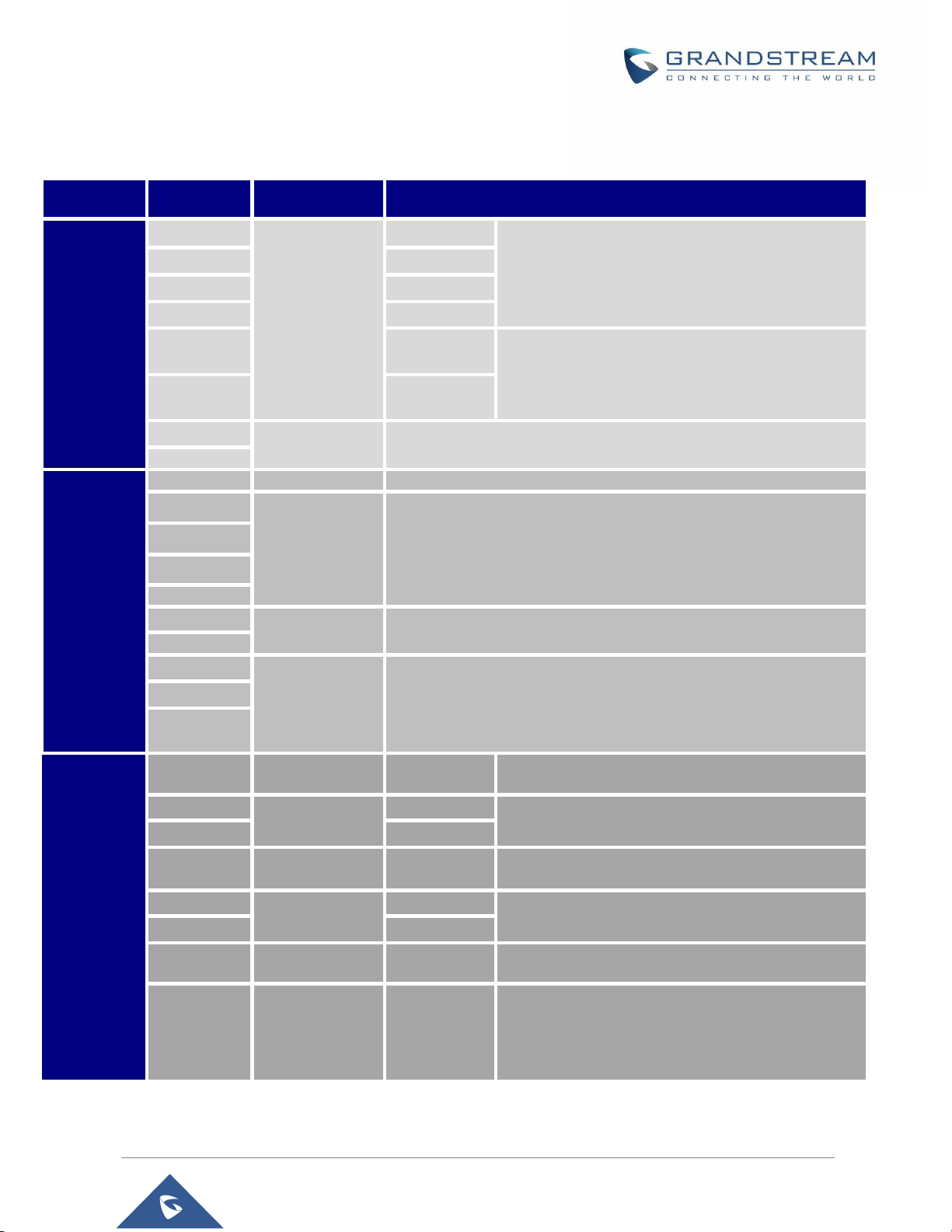
Feature Highlights
The following table contains the major features of the GDS3710.
Table 1: GDS3710 Features in a Glance
Technical Specifications
The following table resumes all the technical specifications including the protocols / standards supported,
voice codecs, telephony features and upgrade/provisioning settings for GDS3710.
Table 2: GDS3710 Technical Specifications
P a g e | 24
Page 25

GDS3710 User Manual
Version 1.0.7.23
Snapshots
Triggered upon events, sent via email and/or FTP.
Multi-stream
Resolution
High-performance streaming server allowing multiple simultaneous accesses:
Primary video stream: 1920 x 1080 resolution for continuous full HD recording.
Secondary video stream: 640 x 480 resolution for SIP/VoIP video calls.
Third video stream: 320 x 240 resolution for smartphone Apps.
Network Protocols
TCP/IP/UDP, RTP/RTCP, HTTP/HTTPS local upload and mass provisioning using
TR-069 (pending), ARP/RARP, ICMP, DNS, DHCP, SSH, SMTP, TFTP, NTP,
STUN, TLS, SRTP.
SIP/VoIP Support
Broad interoperability with most 3rd party SIP/VoIP devices and leading
SIP/NGN/IMS platforms.
Voice Codecs
G.711µ/a-law, G.722, G.729A/B, DTMF (RFC2833, SIP INFO), AEC.
QoS
Layer 2 QoS (802.1Q, 802.1P) and Layer 3 QoS (ToS, DiffServ, MPLS).
Security
User and administrator level access control (pending), MD5 and MD5-sess based
authentication, 256-bit AES encrypted configuration file, TLS, SRTP, HTTPS,
802.1Q.
Upgrade /
Provisioning
Firmware upgrade via TFTP/HTTP/HTTPS, mass provisioning using TR-069
(Pending) or AES encrypted XML configuration file.
Audio Input
Built-in Digital Microphone, up to 1.5m with AEC.
Audio Output
Built-in HD Loudspeaker (2 Watt), sound quality suitable for up to 3 m.
Keypad / Buttons
12-key touchpad plus a capacitive doorbell button, each with individual LED
illumination.
RFID
125KHz: EM4100 (1 RFID card and 1 RFID key fob included).
Alarm Input
Yes, 2 channels, Vin < 15V, for door sensor or other devices.
Alarm Output
Yes, 2 channels, 125VAC/0.5A, 30VDC/2A, Normal Open or Normal Close, for
electric lock, light switch or other devices.
Network Interface
10M/100M auto-sensing.
Expansion Interface
Wiegand (26 bits) input and output.
Dimensions and
Weight
173mm(H) x 80mm(W) x 36mm(D).
0.6 Kg.
Power Supply
PoE (Power over Ethernet) IEEE 802.3af Class 3, or 12VDC/1A connection (AC
power adapter not included).
Interoperability
ONVIF (Profile S).
Ingress Protection
Weatherproof, vandal resistant, with support for extra back reinforcing metal plate
Temperature and
Humidity
Operation: -30°C to 60°C (-22°F to 140°F)
Storage: -35°C to 60°C (-31°F to 140°F)
P a g e | 25
Page 26

GDS3710 User Manual
Version 1.0.7.23
Humidity: 10% to 90% Non-condensing
Protection Class
IP66 (EN60529), IK09 (IEC62262).
Compliance
FCC: Part 15 subpart B Class B; Part 15 C; MPE
CE: EN 55032 Class B; EN 61000-3-2; EN 61000-3-3; EN 50130; EN 60950-1; EN
300330; EN 301489; EN 62311
RCM: AS/NZS CISPR 22; AS/NZS 4268; AS/NZS 60950.1
IC: ICES-003; RSS310
P a g e | 26
Page 27
GDS3710 User Manual
Version 1.0.7.23
GETTING STARTED
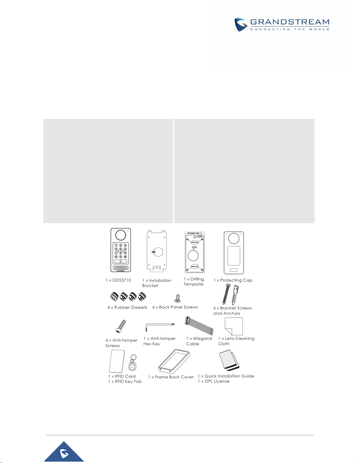
1 x GDS3710
1 x Installation Bracket
1 x Drilling Template
1 x Protecting Cap
4 x Rubber Gaskets (for sealing the
back cable)
6 x Back Panel Screws
6 x Bracket Screws and Anchors
4 x Anti-tamper screws
1 x Anti-Tamper Hex Key
1 x Wiegand Cable
1 x Lens Cleaning Cloth
1 x RFID Card (more can be purchased
from Partner/reseller)
1 x Key Fob (more can be purchased from
Partner/reseller)
1 x Frame Back Cover
1 x Quick Installation Guide
1 x GPL License
This chapter provides basic installation instructions including the list of the packaging contents and
information for obtaining the best performance using the GDS3710 Video Door System.
Equipment Packaging
Table 3: Equipment Packaging
Note: Check the package before installation. If you find anything missing, contact your system administrator
Figure 1: GDS3710 Package
P a g e | 27
Page 28
GDS3710 User Manual
Version 1.0.7.23
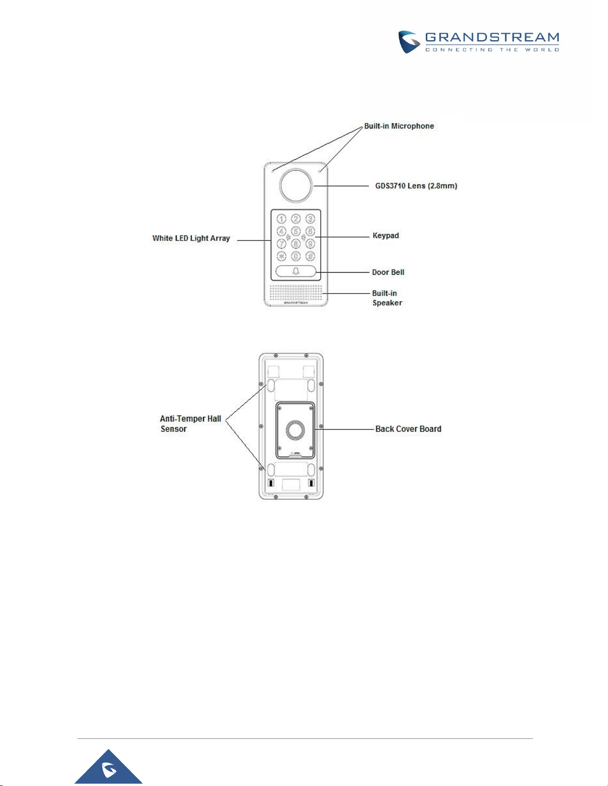
Description of the GDS3710
Below figures show the component of the back and front view of GDS3710 IP Video Door System:
Figure 2: GDS3710 Front View
Figure 3: GDS3710 Back View
Connecting and Setting up the GDS3710
The GDS3710 can be powered using PoE or PSU:
Using PoE as power supply (Suggested)
Connect the other end of the RJ45 cable to the PoE switch.
PoE injector can be used if PoE switch is not available.
Using the power adapter as power supply (PSU not provided)
Connect the other end of the RJ45 cable to network switch or router.
Connect DC 12V power source via related cable to the corrected PIN of the GDS3710.
P a g e | 28
Page 29
GDS3710 User Manual
Version 1.0.7.23
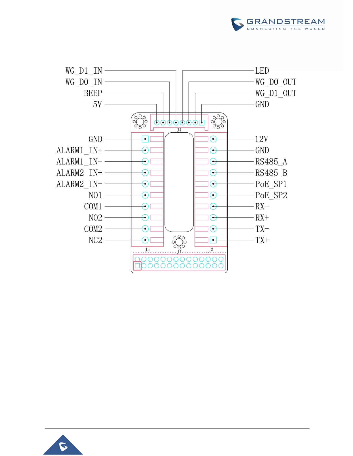
GDS3710 Wiring Connection
Jack
Signal
Function
Note
J2 (Basic)
3.81mm
TX+
Ethernet
PoE 802.3af
Class 3, 12.95W
Orange / White
Data
TX-
Orange
RX+
Green / White
RX-
Green
PoE_SP2
Blue +
Blue/White
Please twist these two wires together and connect to
SP1, SP2 respectively even the PoE NOT used.
PoE_SP1
Brown +
Brown/White
GND
Power Supply
DC 12V, 1A Minimum
12V
J3
(Advanced)
3.81mm
GND
Alarm GND
ALARM1_IN+
Alarm In
Vin<15V
ALARM1_IN-
ALARM2_IN+
ALARM2_IN-
NO1
Alarm Out
Relay: 30VDC/2A; 125VAC/0.5A
COM1
NO2
Electric Lock
For "Fail Secure" (Locked when Power Lost) Strike, connect COM2 &
NO2.
For "Fail Safe" (Open when No Power) Magnetic Lock, connect COM2 &
NC2.
Relay: 30VDC/2A; 125VAC/0.5A
COM2
NC2
J4 (Special)
2.0mm
GND
Wiegand Power
GND
Black
Both Input and Output MUST be connected
WG_D1_OUT
Wiegand Output
Signal
Orange
GDS3710 function as Output of Card Reader, Connect
Pin 1, 2, 3
WG_D0_OUT
Brown
LED
Wiegand Output
LED Signal
Blue
For External Card Reader; Or GDS3710 as Receiver
Only
WG_D1_IN
Wiegand Input
Signal
White
For External Card Reader
Connect Pin 1,4,5,6,7,8
WG_D0_IN
Green
BEEP
Wiegand Output
BEEP Signal
Yellow
For External Reader Only
5V
Wiegand Power
Output
Red
For External Card Reader Only.
12VDC powered External Card Reader must use own
power source, can NOT use this Pin.
Table 4: GDS3710 Wiring Connection
P a g e | 29
Page 30
GDS3710 User Manual
Version 1.0.7.23
GDS3710 Back Cover Connections
Figure 4: GDS3710 Back Cover Connections
Connection Example
To connect the GDS either by using PoE or PSU follow steps below:
Open the Back-Cover Board of the GDS3710 which should look like following figure.
P a g e | 30
Page 31

GDS3710 User Manual
Version 1.0.7.23
Figure 5: GDS3710 Back Cover
Power the unit using PoE
Cut into the plastic sheath of your Ethernet cable, then Unwind and pair as shown below.
Use the TIA/EIA 568-B standard, which define pin-outs for using Unshielded Twisted Pair cable and
RJ-45 connectors for Ethernet connectivity.
Figure 6: Connection Example
Connect each wire of the cable to its associate on the Back Cover of the GDS3710 to power the
unit using PoE.
Power the unit using PSU
To power the unit using PSU, use a multimeter to detect the polarity of your Power Supply, then
connect GND to negative pole and 12V to positive pole of the PSU.
P a g e | 31
Page 32

GDS3710 User Manual
Version 1.0.7.23
Note: If the user doesn’t have PoE switch, there is no need to connect the Blue and Brown wires to the
GDS3710 since these wires are used to power the unit via Ethernet.
Figure 7: Powering the GDS3710
P a g e | 32
Page 33

GDS3710 User Manual
Version 1.0.7.23
GETTING TO KNOW GDS3710
The GDS3710 has an embedded Web server to respond to HTTP/HTTPS GET/POST requests. Embedded
HTML pages allow users to configure the GDS3710 through Microsoft Internet Explorer or Mozilla Firefox.
Download WebControl Plug-in from the GDS3710 WebGUI. For Apple platform OS-X, only MJPEG video
codec supported currently.
Notes:
Please disable temporarily the Antivirus or Internet Security Software when download and install the
Grandstream WebControl Plug-in for Firefox/Chrome or “GSViewerX.cab” for Microsoft Internet
Explorer. Please close Browser to install the downloaded Plug-in or Active-X.
Please trust and install the file downloaded if prompted by the Antivirus or Security software.
Connecting GDS3710 to Network with DHCP Server
The GDS3710 by default has a DHCP client enabled, it will automatically get IP address from DHCP server.
Windows Platform
Two ways exist for Windows user to get access to the GDS3710:
UPnP
By default, the GDS3710 has the UPnP feature turned ON. For customers using Windows network with
UPnP turned on (most SOHO routers support UPnP), it is very easy to access the GDS3710:
1. Find the “Network” icon on the windows Desktop.
2. Click the icon to get into the “Network”, the GDS3710s will list as “Other Devices” shown like below.
Refresh the pages if nothing displayed. Otherwise, the UPnP may not be active in the network.
Figure 8: Detecting GDS3710 via UPnP
P a g e | 33
Page 34

GDS3710 User Manual
Version 1.0.7.23
3. Click on the displayed icon of related GDS3710, the default browser (e.g.: Internet Explorer, Firefox
or Chrome) will open and connect directly to the login webpage.
Figure 9: GDS3710 Login Page
4. Once logged in, the prompt message will display asking for plug-in installation.
5. Disable security or antivirus software, download and install the plug-in, close and open the browser
again, the embedded video will be displayed if clicking the “LiveView” and pressing the stream number.
GS Search
GS search is a program that is used to detect and capture the IP address of Grandstream devices, below
are instructions for using the “GS Search” utility tool:
1. Download the GS Search utility tool from Grandstream website using the following link:
http://www.grandstream.com/sites/default/files/Resources/GS_Search.zip
2. Double click on the downloaded file and the search window will appear.
3. Click on button to start the discovery for Grandstream devices.
4. The detected devices will appear in the output field like below.
P a g e | 34
Page 35

GDS3710 User Manual
Version 1.0.7.23
Figure 10: GS Search Discovery
5. Double click on a device to access its webGUI.
GDS Manager Utility Tool
User can know the IP address assigned to the GDS3710 from DHCP server log or using the Grandstream
GDS Manager after installing this free utility tool provided by Grandstream. User can find instructions below,
for using “GDS Manager” utility tool:
1. Download the GDS Manager utility tool from Grandstream website using the following link:
http://www.grandstream.com/sites/default/files/Resources/gdsmanager.zip
2. Install and run the Grandstream GDS Manager, a client/server architecture application, the server
should be running first, then GDSManager (client) later:
3. On the GDS Manager access to Device Search and Click on the button to start device
detection
4. The detected devices will appear in the output field like below:
P a g e | 35
Page 36

GDS3710 User Manual
Version 1.0.7.23
Figure 11: GDS3710 Detection
5. Double click the column of the detected GDS3710, the browser will automatically open and show the
device’s web configuration page.
6. The browser will ask for plug-in if not installed, please authorize the installation of the plug-in.
7. Enter the administrator user name and password to access the Web Configuration Interface, the default
admin username is “admin” and the default random password can be found at the sticker on the
GDS3710.
8. The plug-in can be downloaded from the GDS3710 Web GUI.
Apple Platform
For Apple users, please turn on Bonjour of Safari to find and access the GDS3710.
1. Open Safari, select “Advanced” to open the Advanced Setting.
2. Click “Include Bonjour in the Bookmarks menu” and “Include Bonjour in the Favorites bar” then close
the setting page and back to Safari.
P a g e | 36
Page 37

GDS3710 User Manual
Version 1.0.7.23
Figure 12: Apple Safari Settings Page
3. Bonjour will now display embedded at Safari. Select “Bonjour” pull-down menu and select “Webpages”,
the related device like GDS3710 will be there.
Figure 13: Bonjour Setting Page
4. Click on the displayed GDS3710 to access to the configuration page of the GDS3710.
5. To see the MJPEG video stream, users should type in the browser the following URL while specifying
the correct protocol (either HTTP or HTTPs and the correct port number) :
http(s)://IP_address_GDS:Port/jpeg/mjpeg.html
Notes:
The instructions provided above are based on Safari/OS-X, other Apple platform like iOS
(iPhone/iPad) can use similar method.
P a g e | 37
Page 38

GDS3710 User Manual
Version 1.0.7.23
iPhone/iPad (iOS) users are recommended to use Applications in Apple Store.
Free or Paid applications from Apple Store like “IP Cam Viewer” is suggested and verified working
with Grandstream GDS3710.
Apple Store applications like “IP Cam Viewer” will support H.264 video codec.
Connect to the GDS3710 using Static IP
If there is no DHCP server in the network, or the GDS3710 does not get IP from DHCP server, user can
connect the GDS3710 to a computer directly, using static IP to configure the GDS3710.
1. The default IP, if no DHCP server, or DHCP request times out (after 3 minutes), is 192.168.1.168
2. Connect the Ethernet cable from GDS3710 to the computer network port directly.
3. Configure the computer using Static IP: 192.168.1.XXX (1<XXX<255, except for 168) and configure
the “Subnet mask” to “255.255.255.0”. Leave the “Default Gateway” to “Blank” like below:
P a g e | 38
Page 39

GDS3710 User Manual
Version 1.0.7.23
Figure 14: Static IP on Windows
4. Power on the GDS3710, using PoE injector or external DC power.
5. Enter 192.168.1.168 in the address bar of the browser, log in to the device with admin credentials. the
default admin username is “admin” and the default random password can be found at the sticker on
the GDS3710.
6. The browser will ask for plug-in or ActiveX if not installed, otherwise it will get to Home page and show
web interface of GDS3710.
7. Access the Web Configuration Interface. Internet Explorer will indicate that “This website wants to
install the following add-on: GSViewerX.cab from Grandstream Networks Inc.”, allow the installation.
Note: Please disable temporarily Antivirus or Internet Security Software and close all browsers when
download and install the Grandstream Plug-in Software.
P a g e | 39
Page 40

GDS3710 User Manual
Version 1.0.7.23
GDS3710 APPLICATION SCENARIOS
The GDS3710 Door System can be used in different scenarios.
Peering Mode without SIP Server
For environment like remote warehouse/storage, grocery store, small (take-out) restaurants, just using
static IP with PoE switch to form a LAN, using Grandstream’s video phone GXV3240 or GXV3275, the
GDS3710 will meet your very basic intercom, open door and surveillance requirement.
This is the solution to upgrade the traditional analogue Intercom and CCTV security system. All you need
is a Power source, Switch or PoE Switch and Grandstream GXV3240 or GXV3275 video phones.
The equipment list can be found below:
GDS3710
GXV3240 or GXV3275
PoE Switch with related Cat5e/Cat6 wiring
Peering using SIP Server (UCM6XXX)
For large deployment, multiple GDS3710 might be required, peered connection will not work in such case
due to multiple connections. Such scenarios require an IPPBX or a SIP Proxy to accomplish the tasks.
If remote access is required, a router with internet access should be added to below needed equipment list:
Several GDS3710
UCM6XXX or another SIP Server
GXV3240 or GXV3275 Video Phones
PoE Switch with related Cat5e/Cat6 wiring
Electronic Lock
If remote access to the GDS3710 is required for viewing live video stream, Internet access is required and
more equipment such as:
Router.
Internet Access (Optical fiber, 3G, 4G, Cable or DSL).
iPhone or Android phone with 3rd party applications (IP Cam Viewer for instance).
P a g e | 40
Page 41

GDS3710 User Manual
Version 1.0.7.23
Figure 15: Peering GDS3710 with UCM6XXX
Using a Network Video Recorder (NVR)
For implementation with more than two GDS3710s, if local video recording is required to store the record,
then a NVR will be added to save all the video stream when people enter the door.
Equipment List:
Several GDS3710
NVR supporting Onvif Profile S.
PoE switches with Cat5e/Cat6 wiring
Router
Internet Access (Optical fiber, 3G, 4G, Cable or DSL).
iPhone or Android phone with 3rd party APP
P a g e | 41
Page 42

GDS3710 User Manual
Version 1.0.7.23
Figure 16: Peering GDS3710 with GVR3550
P a g e | 42
Page 43

GDS3710 User Manual
Version 1.0.7.23
GDS3710 PERIPHERAL CONNECTIONS
Below is the illustration of GDS3710 peripheral connections for related applications.
Figure 17: Peripheral Connections for GDS3710
P a g e | 43
Page 44

GDS3710 User Manual
Version 1.0.7.23
Alarm IN/OUT
Alarm Input
3V<Vin<15V, PINs (1.02KΩ)
Alarm Output
125VAC/0.5A, 30VDC/2A, Normal Open, PINs
Alarm_In could use any 3rd party Sensors (like IR Motion Sensor).
Alarm_Out device could use 3rd party Siren and Strobe Light, or Electric Door Striker, etc.
The figure below shows illustration of the Circuit for Alarm_In and Alarm_Out.
Figure 18: Alarm_In/Out Circuit for GDS3710
Notes:
The Alarm_In and Alarm_Out circuit for the GDS3710 should meet the following requirement:
The Alarm_In circuit, if there is any voltage change between 3V and 15V, as specified in the table
above, the GDS3710 Alarm_In port will detect it and trigger the action and event.
Higher voltage and wrong polarity connection are prohibited because this will damage the devices.
Protection Diode
When connecting the GDS3710 to a door strike it is recommended to set an EMF protection diode in reverse
polarity for a secure use, below examples of deployment for the protection diode.
P a g e | 44
Page 45

GDS3710 User Manual
Version 1.0.7.23
Figure 19: Protection Diode - Example 1
The reverse EMF protection diode must always be installed in reverse polarity across the door strike.
Figure 20: Protection Diode - Example 2
Note: power polarity connection: Diode: SS24 or If>=2A, Vr>=40V.
Connection Examples
Below examples, show how to use wiring on the back cover of the GDS3710 to connect with external
devices. The “NO” (Normal Open) model strike is used as example, “NC” (Normal Closed) should be similar
and users need to decide which model (NO or NC) to be used on the door.
P a g e | 45
Page 46

GDS3710 User Manual
Version 1.0.7.23
Wiring Sample using 3rd Party Power Supply
Figure 21: 3
rd
party Power Supply Wiring Sample
Wiring Sample using Power Supply for both GDS3710 and Electric Strike
Figure 22: Power Supply used for both GDS3710 and Electric Strike
P a g e | 46
Page 47

GDS3710 User Manual
Version 1.0.7.23
Wiring Sample using PoE to power GDS3710 and 3rd Party Power Supply for Electric Strike
Figure 23: Wiring Sample using PoE to power GDS3710 and 3
rd
party Power Supply for Electric Strike
Warning: The following example should be avoided when powering the electric strike.
Figure 24: Example to Avoid when Powering the Electric Strike
P a g e | 47
Page 48

GDS3710 User Manual
Version 1.0.7.23
Good Wiring Sample for Electric Strike and High-Power Device
Figure 25: Electric Strike and High-Power Device Example
Wiegand Module Wiring Examples
GDS3710 package is shipped with one Wiegand cable for Input/Output Wiegand connections. The following
examples shows how to connect the Wiegand Input/Output devices to the GDS3710.
Input example with 3rd party power supply for Wiegand device
Figure 26: Wiegand Input Example with 3
rd
party Power Supply
P a g e | 48
Page 49

GDS3710 User Manual
Version 1.0.7.23
Make sure to connect the GND of the Wiegand device and the GDS3710 Wiegand port.
For Wiegand input mode, LED and Beep pins require that the Wiegand device support those interfaces.
These two pins will not affect the Wiegand bus when not connected.
Input example with power supply for both GDS3710 and Wiegand device
Figure 27: Wiegand Input Example with Power Supply for GDS3710 and Wiegand Device
If power source is 12VDC, Wiegand device can share same power source of GDS3710. However, users
need to check the max power consumption and the max capability of the power source.
If Wiegand device is using 5VDC, GDS3710 Wiegand port can provide 5VDC with max 500mA to power up
Wiegand device.
Output example with 3rd party power supply for Wiegand device
Figure 28: Wiegand Output Wiring Example
P a g e | 49
Page 50

GDS3710 User Manual
Version 1.0.7.23
When the Wiegand output of the GDS3710 is connected, it acts as the signal receiver of the 3rd party
Wiegand device, connecting to door controller. The major wiring is GND, D0, and D1. Because usually the
door controller will consume big current and power, the power supply should be separated.
Wiegand RFID Card Reader Example
Figure 29: Wiegand RFID Card Reader Example
Siren alarming when door opened abnormally
When this feature enabled (special wiring required, see below wiring diagram), abnormal open door will be
detected by DI port (Alarm_In2 or IN2 in below diagram showed) if wired correctly (connecting the COMx
port to DIx port) therefore trigger siren alarm. Once abnormal open door alarm triggered, the siren will sound
non-stop, until manually override by related person.
There are several ways to stop and disable the alarm:
1) Power cycle the GDS37xx
2) Pick up the Alarm Phone Call (if configured)
3) Open Door using PIN (either public PIN or private PIN)
Once alarm triggered, the GDS3710 will take snapshots when the abnormal open door happened, email
and upload the snapshots to FTP or Central Server (when configured); call the configured alarm SIP phone,
send the alarm output (if connected). User will only be able to disable the siren using the 3 methods
mentioned above.
Detailed action information please refer to GDS37xx User Manual, “Alarm Action Settings” configuration.
P a g e | 50
Page 51

GDS3710 User Manual
Version 1.0.7.23
Below are some diagrams showing the correct wiring to enable this new security enhancement feature:
GDS3710 Connection: IN2 set as Normal Close and “Fail Safe” Electric Strike using 3rd Party Power Supply
Figure 30: Digital Input set as Normal close
Figure 31: “Fail safe” Electric Strike using 3rd Party Power Supply
GDS3710 Connection: IN2 set as Normal Open and “Fail Secure” Electric Strike using 3rd Party Power Supply
Figure 32: Digital Input set as Normal open
P a g e | 51
Page 52

GDS3710 User Manual
Version 1.0.7.23
Figure 33: “Fail Secure” Electric Strike using 3rd Party Power Supply
GDS3710 Connection: IN2 set as Normal Open and “Fail Secure” Electric Strike using 3rd Party Power Supply with Door sensor
Figure 34: “Fail Secure” Electric Strike using 3rd Party Power Supply with Door Sensor
P a g e | 52
Page 53

GDS3710 User Manual
Version 1.0.7.23
GSC3570 Secure Open Door via GDS37XX/GSC3570 Peering
This secure open door new feature is a major enhancement to GDS37xx, but need to include GSC3570 to
make it a whole solution. The GDS37xx/GSC3570 will be peering together in LAN/WAN via IP/SIP, the door
lock/strike will be wired to GSC3570Alarm_Out port and controlled by GSC3570. This way the strike control
is inside the building with enhanced security. Below is a setup example:
Figure 35: GSC3570 secure open door via GDS3710
Note:
Minimum firmware required for this to work:
•Outdoor Device: GDS3710(FW1.0.7.19) and GDS3705(FW1.0.1.13)
•Indoor Device: GSC3570(FW1.0.5.2)
The GDS37xx can be powered via PoE; the GSC3570 can connect to same network via PoE or WiFi. For
open door combination with GSC3570 and GDS37xx, if GSC3570 needs to control multiple GDS37xx,it has
to use SIP and the related GDS37xx will control the strike/lock. The different GDS37xxdoorbell call will
have“ One Button Open Door” displayed when in “Preview” (early media support) or when call
established.
The GSC3570 user will press the virtual button on touch screen to remotely open the door controlled by the
related GDS37xx.There is no door limitation for such usage but only ONE DOOR can be opened at one
time. It is just a SIP call open door application, but strike/lock control circuit is located outdoor.
For “Secure Open Door”, the GSC3570 is peering with GDS37xx. The GSC3570 controlling the
relay/strike/lock from inside the building (Unlike GDS37xxinstalled outside), but only ONE door can be
controlled because GSC3570 only has one Relay Control circuit build in.
P a g e | 53
Page 54

GDS3710 User Manual
Version 1.0.7.23
This peering can be via LAN/WAN but LAN is recommended and actually most of the application scene are
in LAN environment because most likely the GSC3570 and GDS37xx are in the same building. Although
SIP/UCM over Internet/WAN also works, it is recommended to use static IP if the GSC3570 (inside) and
GDS37xx(outside) are at same location in the same LAN.
This setup is much simple and reliable in case there is network outage like Internet/UCM is down.
For the GSC3570 and GDS37xxpeering, it can be used via SIP only (Cloud or UCM); IP only (No SIP proxy
or UCM but static IP address) and Mixed (SIP and fallback to IP if Proxy failed).
GDS3710 Web Configuration
This setup can be found under device web UI→Door System Settings →Basic Settings:
Figure 36: GSC3570 secure open door via GDS3710-GDS3710 configuration
GSC3570 Web Configuration
The GSC3570 side also need to be configured according, like below:
Figure 37: GSC3570 secure open door via GDS3710-GSC3570 Door System System configuration
Then we will be configuring the Digital Input on the GSC3570 as the figure below:
Figure 38: GSC3570 secure open door via GDS3710-GSC3570 Digital Input configuration
P a g e | 54
Page 55

GDS3710 User Manual
Version 1.0.7.23
Notes:
If the solution/integration is using static IP address without SIP Proxy, all the devices involved
(GDS/GSC/IP Phone) should choose “NAT Traversal” to “No” and should NOT “Use Random Port”,
otherwise will have problem of ghost call (SIP signaling working but NO media).
The IP phone or GSC3570 can use any empty SIP account, meaning it can be mixed if
Account 1 registered to UCM/Proxy and Account2 (blank) to use IP (but the account has to be
configured as “Active”).
One-Way Interlocking Mode
This feature will allow GDS3710 to control two doors in one direction, with additional 3rd party window/door
sensor installed accordingly (not provided by Grandstream). When configured and wired correctly, the two
doors will operate under a controlling logic as below:
1) Only legal PIN or RFID card can open door when BOTH doors are detected closed.
2) When 1st door opened by valid user, the 2nd door is and will remain closed; the 2nd door will automatically
open once detected the 1
3) When 2nd door opening, the 1
st
door closed and programmed timer reached.
st
door will NOT open even a valid PIN/RFID used.
4) If entering 1st door and after 1st door closed and 2nd door opened, the person failed to enter 2nd door
promptly (after 2nd door opening time out) will be locked in between two doors until next transaction happens
or ask help (e.g.: call posted number or press button if there is one) from security staff to open door remotely
(via SIP call into GDS3710 or GDSManager, for example).
This open door logic will make sure two doors are open in “One-Way” direction, at any given time only one
door can be opened, and only one legal open door request is allowed to execute.
The hallway or scene between two doors could be monitored by installing Grandstream IP cameras.
This feature can be used in application scene like: College Dorm, Bank Branches, Government Offices,
Medical Clinics, Private Clubs, etc., where there are two doors in place, high security and flow control is
required (only one entry per time) but security guard may not be on site always.
Below is the illustrating drawing of the application scene:
P a g e | 55
Page 56

GDS3710 User Manual
Version 1.0.7.23
Figure 39: One-Way Interlocking Mode Diagram Example
Below is the wiring sample to implement this feature:
Note:
If required to use the same two doors for “Exit” direction, another GDS3710 is required and it can be
configured in Door 2 to control “Exit” direction. The wiring/connection will be mirrored.
Web Configuration
This option can be found under device web UI→Door System Settings. Below example configuration
screenshots are for reference only, customers need to test and get own parameters in field:
Figure 40: One-Way Interlocking Mode_GDS3710_Configuration_1
P a g e | 56
Page 57

GDS3710 User Manual
Version 1.0.7.23
Notes:
- Door 2 Delay before Unlock(s): Will be the total transit time from Door 1 to Door 2 right after the
Door 1 is closed (this time will be “Door 1 unlock holding time”).
- In above example, the Door1 unlock holding time is 2 seconds, the transit time of hallway is 6
seconds, therefore the Door 2 Delay before Unlock is set to 8 seconds.
- The transit time and unlock holding time will be decided and adjusted based on actual application
scene by the installer or system integrator.
- COM1 (ALMOUT1) only has two sockets for wiring, and NO ONLY. If the connected strike/lock is a
NO strike, this means ALMOUT1 Status should be set to “Normal Open” then door will be closed
when power is lost.
Digital Input to Check Door Status (Door 1 & Door 2
Figure 41: One-Way Interlocking Mode_GDS3710_Configuration_2
Proceed to Alarm Settings →Alarm Events Config →Digit Input, configured as follow:
- Digit Input 1: Door Status Check. The DI will validate the current status of the Door, whether it is
close or open, based on the sensor signal sending to the “Digit input 1.
- Digit Input 1 Status: If set to Normal Open: Configured door status check will be triggered when
Digital Input Status switch from Close to Open, If set to Normal Close: Configured door status
check will be triggered when Digital Input Status switch from Open to Close. By default, Input Digit
1 Status is “Disabled”.
- Digit Input 2: Door Status Check. The DI will validate the current status of the Door, whether it is
close or open, based on the sensor signal sending to the “Digit input 2”.
P a g e | 57
Page 58

GDS3710 User Manual
Version 1.0.7.23
- Digit Input 2 Status: If set to Normal Open: Configured door status check will be triggered when
Digital Input Status switch from Close to Open, if set to Normal Close: Configured door status
check will be triggered when Digital Input Status switch from Open to Close. By default, Input Digit
2 Status is “Disabled.
Notes:
- “Alarm Schedule” and “Alarm Action Profile” must be configured and selected otherwise the Digit
Input channel will not be activated.
- There are two doors wired with window/door sensor separately, please make sure the door sensor
is wired to correct Digit Input channel and refer to sample wiring diagram for reference [Figure 39:
One-Way Interlocking Mode Diagram Example].
P a g e | 58
Page 59

GDS3710 User Manual
Version 1.0.7.23
Open Door via GDS37xx with or without a SIP Call
This feature needs related matching GDS37XX firmware to work. The minimum firmware version needed:
GDS3710: 1.0.7.19 or higher.
GDS3705: 1.0.1.13 or higher.
From GDS37XX side, the configuration is the same. Only difference is the number of doors be controlled:
If using Local Relay controlled by GDS37XX, TWO DOORS can be controlled.
If using GSC3570 Relay, ONLY ONE DOOR can be controlled. The PIN and other settings are the same
as SIP remote open door or GSC3570 secure open door.
The difference will come out at the touch screen UI operation of GSC3570.
Figure 42: GDS37XX Configuration Example
Figure 43: GSC3570 Configuration Example
P a g e | 59
Page 60

GDS3710 User Manual
Version 1.0.7.23
Door opening with SIP Call:
When GSC3570 established call with GDS37XX, the screen will display virtual open door button(s), and
user will press the button to open door:
Figure 44: Open Door with SIP Call
GSC3570 Open Door NO SIP Call:
At the GSC3570 idle screen, press “Monitor →Door system”, the related GDS37XX will be displayed.
In the blue bar, left is a “Phone”icon and right is the “Open door”icon. The“Phone”icon will
establish SIP call as previous firmware behaved.
Press “Open door” icon, the GSC3570 will open door directly and NO SIP CALL will be established.
Depending on how many doors controlled, if one door configured, the door will open directly; if two doors
configured, another screen will pop up to allow user to choose which door to open, as shown below:
Figure 45: Open Door without SIP Call
When the door is successfully opened the following message will appear:
Figure 46: Open Door without SIP Call
P a g e | 60
Page 61

GDS3710 User Manual
Version 1.0.7.23
GDS3710 HOME WEB PAGE
Number
Fields
Description
1
LiveView
Access to live view stream page.
2
Door System
Settings
Access to “Door System Settings” page.
3
System Settings
Access to “System Settings” page.
4
Account
Access to “Account” configuration page.
5
Phone Settings
Access to “Phone Settings” configuration page.
20
21
Once logged in successfully to the GDS3710, user will see the following page.
Note: the options displayed might differ from browser to another.
Figure 47: Home Page: Internet Explorer 11
Table 5: Home Page Description
P a g e | 61
Page 62

GDS3710 User Manual
Version 1.0.7.23
6
Video & Audio
Settings
Access to “Video & Audio settings” page.
7
Alarm Settings
Access to “Alarm settings” page.
8
Email & FTP Settings
Access to “Email & FTP Settings” page.
9
Maintenance
Access to “Maintenance” page.
10
Status
Click to enter “Status” page.
11
Play/Stop
Start/Stop the video stream in the web page.
(Internet Explorer 11)
12
Stream 1
Play the primary stream.
13
Stream 2
Play the secondary stream.
14
Stream 3
Play the third stream.
15
Window size
Resize the window. (Internet Explorer 11)
16
Audio
Click to mute / unmute the audio. (Internet
Explorer 11)
17
Snapshot
Click to take a snapshot. (Internet Explorer 11)
18
Recording
Click to start recording. (Internet Explorer 11)
19
File Path Saved
Click to access Record and Capture paths.
(Internet Explorer 11)
20
Logout
Logout from the web page.
21
Language
Select the webpage language.
GDS3710 Configuration & Language Page
Once the IP address of the GDS3710 is entered on the user browser, the login web page will pop
up allowing user to configure the GDS3710 parameters.
When clicking on the “Language” drop down, supported languages will be displayed as shown in
Figure below. Click to select the related webpage display language.
P a g e | 62
Page 63

GDS3710 User Manual
Version 1.0.7.23
Figure 48: Switch Language Page
Note: Current firmware supports only English (default) and simplified Chinese.
P a g e | 63
Page 64

GDS3710 User Manual
Version 1.0.7.23
GDS3710 SETTINGS
Live View Page
This page allows users to view the live video of the GDS3710 using popular browsers like Chrome or Firefox
immediately without downloading and installing any plugins.
Figure 49: Live View Page: Google Chrome
Three streams are available:
Primary video stream: 1920*1080 resolution, recommended for continuous full HD recording (If used
with GXV355X NVR).
Secondary video stream: 640*480 resolution, recommended for SIP/VoIP video calls (if used with
GXV3240/GXV3275).
Third video stream: 320*240 resolution, recommended for smartphone or Tablet Apps (IP Cam Viewer
for instance).
Live Snapshot
Users can take view snapshots from GDS3710 live view via HTTP API, this can be used without installing
the any browser plugin. Starting from firmware 1.0.3.34, users can deploy two methods to view snapshots
depending on JPEG Authentication Mode, which can be set under following path:
Web UI System Settings Access Settings
P a g e | 64
Page 65

GDS3710 User Manual
Version 1.0.7.23
Figure 50: MJPEG Authentication Mode
1) Challenge+Response MJPEG Authentication Mode:
Please follow below steps in order to take a snapshot via HTTP commands on this mode:
1. In browser type in: http(s)://IP_Address_GDS:Port/jpeg/view.html
2. The browser will pop up the window above asking for credentials, user needs to enter admin
credential.
Figure 51 : Snapshot admin credential
3. The browser will show one frame of the video (720p) as a snapshot.
P a g e | 65
Page 66

GDS3710 User Manual
Version 1.0.7.23
Figure 52 : Snapshot view using secured MJPEG authentication Mode
Note: This is supported on all browsers without installing any plugin and requires admin user authentication
for more security.
2) Basic MJPEG Authentication Mode:
Please follow below steps in order to take a snapshot via HTTP commands:
1. In browser type in: http(s)://admin:password@IP_Address_GDS:Port/jpeg/view.html
2. The browser will show one frame of the video (720p) as a snapshot.
P a g e | 66
Page 67

GDS3710 User Manual
Version 1.0.7.23
Figure 53: Snapshot view using Basic Authentication Mode
MJPEG Stream
The GDS3710 supports MJPEG Stream live viewing via HTTP API commands, this can be used without
installing the Live view browser plugin. Starting from firmware 1.0.3.34, users can deploy two methods to
retrieve MJPEG stream depending on JPEG Authentication Mode, which can be set under following path:
Web UI System Settings Access Settings
Figure 54: MJPEG Authentication Mode
1) Challenge+Response MJPEG Authentication Mode:
P a g e | 67
Page 68

GDS3710 User Manual
Version 1.0.7.23
In order to get live view stream using MJPEG stream over HTTP command on this mode, please fellow
below steps:
1. In browser type in: http(s)://IP_Address_GDS:Port/jpeg/mjpeg.html
2. The browser will pop up the window above asking for credentials, user needs to enter admin
credential.
Figure 55 : MJPEG view admin credential
P a g e | 68
Page 69

GDS3710 User Manual
Version 1.0.7.23
3. The browser will show MJPEG stream (720p).
Figure 56 : MJPEG live view using secured MJPEG Authentication Mode
Note: This is supported on all browsers without installing any plugin and requires admin user authentication
for more security.
2) Basic MJPEG Authentication Mode:
Please follow below steps in order to take a snapshot via HTTP commands:
1. In browser type in: http(s)://admin:password@IP_Address_GDS:Port/jpeg/mjpeg.html
2. The browser will show MJPEG stream (720p).
P a g e | 69
Page 70

GDS3710 User Manual
Version 1.0.7.23
Figure 57: MJPEG view using Basic MJPEG Authentication Mode
Note: Similar command can be applied to open source application like VLC MediaPlayer to retrieve H.264
video stream with better quality: rtsp://admin:password@IP_GDS3710:Port/X
Where X=0,4,8 corresponded to 1st, 2nd and 3rd video stream (2
nd
recommended).
Door System Settings
Users can configure system operations parameters, like input PIN for the door and manage users’ settings.
Basic Settings
P a g e | 70
Page 71

GDS3710 User Manual
Version 1.0.7.23
Figure 58: Door System Settings Page
P a g e | 71
Page 72

GDS3710 User Manual
Version 1.0.7.23
Table 6: Door System Settings
Door Relay Options
This feature allows customers to integrate GDS37XX with 3rd party web
relay to control door open over network, via script or other applications, to
meet real application scene and enhance security. User need to input web
relay IP address or domain name, as well as authentication information,
to make this to work.
There are two choices in the pull-down selection: Local Relay and
Webrelay.
Local Relay: Local Relay is the GDS3710 controlling the relay.
The strike is wired into the COM2 or COM1 port of the GDS3710
depending 1 door or 2 door need to be controlled.
Webrelay: When Webrelay is selected, customers need to
continue configure the webrelay IP address or domain name,
together with credentials like Username and Password. When
legal open door event happened, the configured web relay will get
the communication from GDS3710, and will operate the strike to
open door for the authenticated open door request.
Note: In web relay mode, the strike is wired to the web relay controller
device.
For more details, please refer to the Webrelay documentation from this
link: webrelay user manual
Webrelay URL ON
When Door relay Option set to Webrelay, then enter the correct URL used
by the third party controller so that the GDS3710 send the command to
activate the relay.
This adds an extra layer of security so when legal open door event
happened, the configured web relay will get the communication from
GDS3710, and will operate the strike to open door for the authenticated
open door request or use that command to operate other industry
application.
Notes:
Now there are two Webrelay URL fields available, with On or Off
URL command allowed or other usage URL command allowed.
Also allow Username and Password configured if the 3rdparty
Webrelay requiring this security feature.
If some 3rdpartyWebrelay only support one URL command, then
just leave another Off URL blank, or put whatever there as long
as it is NOT a URL command.
P a g e | 72
Page 73

GDS3710 User Manual
Version 1.0.7.23
Webrelay URL OFF
When Door relay Option set to Webrelay, then enter the correct URL used
by the third party controller so that the GDS3710 send the command to
disable the relay.
Webrelay Username
Enter the web relay username.
Webrelay Password
Enter the web relay password.
ALMOUT1 Feature
This option allows to choose to use Alarm_Out (COM1) interface for either
as alarm out with 3rd party device, or to control a second door “Door 2”
(the two functions are mutual exclusive).
When option “Open Door” is selected, will enable GDS3710 to control the
operation of two doors via RFID, local and remote PINs.
ALMOUT1 Status
Select Normal Open or Normal Close depending on the lock used.
Delay before Unlock (s)
Device will open door after specified delay (in seconds) when user issuing
the authorization.
Unlock Holding Time (s)
Configures the lock holding time, in seconds (default value is 5 seconds).
Device will hold the door unlocked for this specified duration.
Range: 1-1800 seconds.
Minimum Interval of
Swiping Card (ms)
Defines the interval in ms to swipe consecutive RFID cards. The range
should be between 0ms and 2000ms.
Number of Snapshots
when Door Opened
Define number of snapshot to be sent by the GDS ( vie FTP or Email)
Maximum up to 4 screenshots.
Snapshot when Door
Opened
User can choose to email the snapshot when door is opened without
sending the snapshots via FTP to the FTP server.
Snapshot when Doorbell
Pressed
User can choose to email the snapshot when doorbell pressed without
sending the snapshots via FTP to the FTP server.
Call Mode
Chooses whether to make call to the SIP number or Virtual Number when
dialing from the GDS3710 keypad.
Doorbell Call Out Account
This option sets the account to be used to make call upon the
doorbell trigger. If set to Auto, the GDS will use the first available account.
Doorbell Mode
Configures the action to be taken when the doorbell is pressed, three
options are available:
Call Doorbell Number: when Doorbell is pressed, a call will be
made to the “Number Called When Door Bell Pressed”
P a g e | 73
Page 74

GDS3710 User Manual
Version 1.0.7.23
Control Doorbell Output (Digital Output 1): when Door Bell is
pressed electronic lock for Output 1 is opened.
Both of Above: When selected, both Call Doorbell Number and
Control Doorbell Output options are enabled.
Door Bell Call Mode
Select the ring strategy for the Numbers Called when pressing the Door
Bell button to be either Serial or Parallel:
Serial Hunting: the configured extensions and/or IP addresses
will ring one after one by order.
Parallel Hunting: The configured extensions and/or IP
addresses will ring simultaneously (up to 4 simultaneous SIP
calls).
Number Called When Door
Bell Pressed
Configures SIP extension number (SIP Server mode), or IP address with
port number (peering mode), to be called when the Door Bell is pressed:
SIP Server mode:
- The field can be configured to store multiple one or multiple SIP
extensions, if configured with multiple extensions (ex: 1001, 1002, 1003),
separated with “,” the GDS3710 will ring one extension after the other in
a Serial Hunting Mode (GDS will ring each extension by default 15
seconds, this can be changed on the Ring Timeout) or ring them
simultaneously in Parallel Hunting Mode.
- When using UCM, users can also configure there a Ring Group
extension (6400 for example) that will ring multiple extensions
simultaneously, or one by one depending on the Ring Group ring strategy.
- If all phones are GXP21XX, the phone will stream the video frame by
frame and users can open door either by pressing Remote_PIN# or by
pressing Open Door button if already configured.
- If early medial is enabled on phone side, user can send the PIN code
using the Open-Door button before answering the call (Of course users
can open the door also after answering the call).
Peering mode:
- User should configure multiple IP addresses of phones instead of SIP
extensions, when Door Bell pressed the GDS3710 will ring the configured
IP Addresses in Serial or Parallel Mode according to Doorbell Call Mode
strategy.
P a g e | 74
Page 75

GDS3710 User Manual
Version 1.0.7.23
- If early media is enabled, the GXV32XX will receive the video stream
while it is ringing, and user can open door by pressing the Open-Door
button if already configured (Of course users can open the door also after
answering the call).
- GXP21XX phones receive the GDS3710 video using JPEG streaming
this means that it will receive video if early media is enabled or disabled.
Note: This field supports a Maximum of 256 characters.
Maximum Number of
Dialed Digits
Configure the maximum digits allowed to dial in the keypad. Once the
configured condition satisfied, the device will send out the digit to call
automatically without pressing #. Disabled if set to 0.
No Key Input Timeout(s)
Defines the timeout (in seconds) for no key entry. If no key is pressed after
the timeout, the digits will be sent out without pressing #. The default value
is 4 seconds. The valid range is from 1 to 15.
Press Doorbell Schedule
Configure a schedule for the Doorbell button, once configured, the
doorbell with turn ON/OFF based on configured schedule. Default setting
is “All Day”.
Remote PIN to Open the
Door
Configures PIN code stored in the GDS3710, remote SIP phone needs to
input and match this PIN (the PIN is sent via DTMF while in call) so that
the GDS3710 can open the door.
Note: For enhanced security, when the call is initiated from GDS then only
the numbers existing in “White List” will be able to use DTMF PIN to open
door remotely.
Local PIN Type
Three options are available: Private Card PIN, Unified PIN or Card and
Private PIN.
Private PIN: Means every member has a private PIN, the GDS will
record who unlocked the door every time. Users need to enter the
following sequence from the GDS3710 to open the door [*Virtual
Number*Private PIN#].
Notes:
1. When Local PIN type is set to private PIN, users can also open
the door by swiping their cards.
2. If “Disable Keypad SIP Number Dialing” is checked, users will be
able to open door using private PIN with following sequence
[Private PIN#].
P a g e | 75
Page 76

GDS3710 User Manual
Version 1.0.7.23
Note: Door can still be opened by Card and with the sequence
[*Virtual Number*Private PIN#].
For more details and conditions, refer to [Disable Keypad SIP
Number Dialing].
Unified PIN: Means all members share a same PIN to unlock the
door. Users need to enter the following sequence from the GDS3710
keypad to open the door [*Local PIN to Open the Door#].
Card & Private PIN: Means every member needs to swipe his card
and enter his private PIN to open the door using the following
sequence [Swipe the card + * Private PIN#]
Local PIN to Open the
Door
Configures PIN stored in GDS3710, input locally this PIN on the GDS3710
keypad will unlock the door.
This feature needs Private PIN, means every member has a private PIN,
the GDS will record who unlocked the door every time.
Users need to enter the following sequence from the GDS3710 to open
the door [*Virtual Number*Private PIN#].
Note: When local PIN type is set to private card PIN, users can also open
the door by swiping their cards.
Local PIN to Open Door
Schedule
Configure a schedule for the Local PIN to open the door. Once configured,
the door opening ability using local PIN with turn ON/OFF based on
configured schedule. Default setting is “All Day”.
Enable DTMF Open Door
When enabled, remote SIP phones can open the door while in call by
entering the remote PIN code configured (the PIN code is sent via DTMF).
Default settings is disabled.
Enable Guest PIN
Enables password entry for guests.
Guest PIN
Configures the password that will be used by guests.
Guest PIN Start Time
Selects the start time when the Guest PIN start to take effect.
Guest PIN End Time
Selects the end time when the Guest PIN will stop working.
Disable Auto Answer
If checked, GDS3710 will not answer incoming calls automatically, users
can press any key to answer the call. Default setting in unchecked.
Enable Doorbell Button to
Hang up Call
If checked, Users can hang up an active call when pressing the doorbell
button. Enabled by default.
P a g e | 76
Page 77

GDS3710 User Manual
Version 1.0.7.23
Disable Keypad (except
the Doorbell Button)
When checked the Keypad will be disabled, only Door Bell button can be
pressed.
Enable On Hook After
Remote Door Opened
When checked calls will be disconnected automatically 5 seconds after
the remote open door event.
Enable HTTP API Remote
Open Door
Enabling this option allows to use HTTP API command to open the door
remotely.
Important note: We will not be responsible for any security problems
resulting from opening the HTTP API remote function, this option is
disabled by default and the user should enable it while knowing how to
mitigate the risk.
Disable Keypad SIP
Number Dialing
When Keypad SIP number Dialing disabled, device will interpret each digit
entry as private-password open door request after pressing #.
Notes:
“Local PIN Type” should choose “Private PIN”.
Dial keypad to make SIP call will NOT work (except for doorbell button
call).
Private PIN must be UNIQUE among users, otherwise the door will
still open but log will NOT tell who opened the door due to duplicated
PIN and whoever user last matched in the database with the Private
PIN will be shown in the log.
Enable Card Issuing Mode
Enables RFID card issuing/program into the GDS3710. When selected
sweeping an RFID card into the GDS3710 will add card information into.
[Card Management]
Card issuing State Expire
Time(m)
Card issuing mode will be automatically disabled when timer reached (The
range of value is 1 – 1440, in minutes).
Enable Key Blue Light
When checked, the blue light will be activated when pressing the
GDS3710 Keys.
Enable Background Light
When checked, the background light will turn on once clicking the
GDS3710 Keys.
Enable Doorbell Blue Light
When enabled, Doorbell LED will light based on the configured Start/End
Time. For instance, this option can be used when GDS is deployed on
dark environment, the GDS will be located easily using Doorbell LED.
Enable Keypad Blue Light
When enabled, Keypad LED (except for Doorbell LED) will light based on
the configured Start/End Time. For instance, this option can be used when
GDS is deployed on dark environment, the GDS will be located easily
using Keypad LED.
P a g e | 77
Page 78

GDS3710 User Manual
Version 1.0.7.23
Central Mode
If enabled, Group/Schedule/Holiday can only be synchronized from the
Central (GDS Manager), local configuration will not be allowed.
If disabled, only local configuration from GDS3710 is allowed.
Key Sensitivity Level
Set the sensitivity level:
Default: with this mode, the GDS3710 is using less sensitivity keypad
parameters which applied to most usage scenes, especially in warm and
high humidity places like tropic regions or places near seaside or riverside
wherehigh humidity weather condition exists, especially in Summer.
High: This option is designed for application scenes located in high
latitude regions normally very cold and user might need to press the
keypad with gloves. Due to the sensitivity is high, false positive might
happen if such parameter used in different place like low latitude
environment.
Notes: Most application scenes the Default setting of this firmware is good
enough for application. Please use Default setting unless the usage scene
really needs high keypad lever sensitivity.
If with default or low sensitivity keypad, the false positive ghost call issue
still happens frequently, that might indicate an inappropriate wiring or
installation, or maybe the hardware faulty. Please contact
Our Grandstream Support for assistance to resolve such problem.
Key Tone Type
Configures the key tones for the GDS3710.
Default: Beeps will be played when pressing the GDS3710 keys.
DTMF: Tones will be played when pressing the GDS3710 keys.
Mute: No sound will be played when pressing keys.
Enable Wiegand Input
This option needs to be enabled when GDS is connected to the wiegand.
output device (RFID card reader for example)
Wiegand Output
This option is to be enabled when the GDS is the wiegand output device.
(example: input device is a door controller)
Notes: Remote SIP phone needs password (digits 0-9 only, ended with # key) matching the configuration
on the web page to open the door (via DTMF).
GDS3710 support RFID for multiple users to open door, therefore every user has its own PIN. For
environment with large number of users (limit is 2000), it’s difficult for the GDS3710 to manage all these
users, so a separate PC or Server should be involved for such kind of management and monitoring.
In environments with large number of users (limit is 2000), the GDS3710, another possibility would be to
set one unified Local PIN for opening the door for all the users.
P a g e | 78
Page 79

GDS3710 User Manual
Version 1.0.7.23
Using Alarm Out (COM 1) to Control a Second Door
Starting from firmware 1.0.5.2, user can now set Alarm_Out (COM1) interface to control a second Door, in
additional to the existing Locker/COM2 interface (controlling Door1).
This feature allows GDS3710 to control the operation of two doors via RFID, local and remote PINs.
For example, a 3rd party Wiegand Input device or GDS3710 can be installed at Door2 with related cable
wired into the control GDS3710 installed at Door1. The Door1 and Door2 can be configured to be open by
programmed RFID cards, PINs either separately or both.
Figure 59: Alarm_Out1 Feature
Interface for Door Control (which Door can be OPEN):
If Alarm_Out (COM1) interface is set to control Door 2 opening, “ALMOUT1 Status” can be configured by
choosing “Normal Open” or “Normal Close” based on the strike used.
Unlike default COM2 which is designed for strike control and having three connecting sockets, the COM1
only has two connecting sockets. Therefore correct lock mode has to be configured to make the strike
working as expected.
For above example, the GDS3710 is configured to control Door1 (wiring to COM2 interface); the 3rd party
Wiegand Input is set to control Door2 (wiring to COM1 interface).
In case of a power loss then the DOOR STATUS when power is off will be depending on the following
situations:
P a g e | 79
Page 80

GDS3710 User Manual
Version 1.0.7.23
COM2 has three wiring PINs, corresponding to NO or NC accordingly. Therefor when connecting
NC2 and COM2 (Fail Safe) then strike will open when power is lost and when using a NO2 strike
(connecting COM2 and NO2) then door is “locked” when power is lost (Fail Secure).
COM1 (ALMOUT1) has only two PIN, and NO ONLY. If the connected strike/lock is a NO strike,
this means ALMOUT1 Status should be set to “Normal Open” then door will be closed when
power is lost, while if the strike connected is NC strike, and ALMOUT1 Status is set to “Normal
Close” then door will be open when power is lost.
Universal PIN for Operation of Doors:
Figure 60: Universal Local PIN
If Unified PIN (Universal PIN) is configured to open door, then which door can be controlled by the PIN is
configured in the UI once “Unified PIN” selected.
For example, like above screenshot, if this universal PIN is set to open both Door1 and Door2, but due to
previous “Control Option” set to open Door1, and “Wiegand Control” set to open Door2, therefore the final
result will be the INTERSECT result of both sets with condition qualified.
Remote PIN to Operation of Doors:
For remote PIN to open door, the PIN can be configured in example down below.
The PIN can be different for Door1 and Door2 and has to be configured correctly in related IP Phone which
will be used to operate “One Key Open Door”.
If BOTH doors need to be opened at the same time, then both Door1 and Doo2 has to be configured with
exactly SAME password or PIN as DTMF open door.
P a g e | 80
Page 81

GDS3710 User Manual
Version 1.0.7.23
Note: For enhanced security, When call is initiated from GDS then only the numbers existing in “Number
Called When Door Bell Pressed”, “Account White Lists” or “Card Management” will be able to use DTMF
PIN to open door remotely.
Figure 61: Remote PIN to Open Door
Private PIN or Card & Private PIN:
Figure 62: Right of Card and Private PIN
P a g e | 81
Page 82

GDS3710 User Manual
Version 1.0.7.23
If using RFID card or Private PIN to open door, then which door can be opened by the RFID card or Private
Keep Door Open
Select the Keep Door Open mode.
Interval of Keep Door
Open (min)
Set the amount of time in minutes where the door will keep opened. Click
to open door immediately.
PIN is configured via “Card Management”, see above screenshot.
Notes:
For all the settings, the final result of which door can be opened is the LOGIC INTERSECT OPERATON of
ALL the sets of condition qualified.
Please refer to our Open Door Flow chart for better understanding on how to configure and control 2 Doors
operation: http://firmware.grandstream.com/GDS3710_opendoors_logic.pdf
Keep Door Open
This feature allows users to set either an immediate or scheduled open door, this will allow usage scene
like schools or similar private or public places where the door needs to keep open at specific time window
and closed otherwise. Also handy for buildings or properties where a seminar needs to be hosted for some
period or lunch breaks in a factory or company where the door keeps open and no access log required then
back to locked with authorized entry after that, by default it’s disabled.
There are two modes under this section:
1- Immediate Open Door (One Time Only Action)
Figure 63: Immediate Open Door
Table 7: Immediate Open-Door Table
Note: When Alarm OUT 1 is set to Open Door then this option would be available separately for each
door.
2- Schedule Open Door (Repeated Action)
P a g e | 82
Page 83

GDS3710 User Manual
Version 1.0.7.23
Keep Door Open
Select the Keep Door Open mode (Schedule Open Door on this case).
Valid Schedule Start
Time
Selects the start time when the door will be opened.
Valid Schedule End
Time
Selects the end time when the door will be locked.
Holiday Mode
Selects the holiday schedule to be included into the Keep Door Open
schedule (Supported for Door 1 and Door 2).
Figure 64: Schedule Open Door
Table 8: Schedule Keep Door Open
Click on Edit schedule to select which periods for each day the door will remain open, as shown on below
screenshot.
P a g e | 83
Page 84

GDS3710 User Manual
Version 1.0.7.23
Figure 65: Edit Schedule
Emergency PIN
Figure 66: Keep Door Open – Emergency PIN
When Keep Door Open option is set to “Disabled”, user is offered the possibility to force closing the door
from the device keypad by dialing the Emergency PIN set to be used.
Example:
1. Fill in the password in Emergency PIN to Disable Keep Door Open, in our example: 2018
2. Open the door using either Immediate/Scheduled Keep Door open
3. enter the following Emergency Password sequence: *2018#
4. After entering the sequence *Emergency PIN#, the GDS will close the door, and when entering
the web GUI, the Keep Door Open section is switched automatically to "Disabled" Option.
Note: When ALMOUT1 Feature is set to Open Door then separated Keep Door Open features would be
available on this page for each door.
P a g e | 84
Page 85

GDS3710 User Manual
Version 1.0.7.23
Card Management
This page allows users to add information about RFID cards, two options are possible either add RFID
cards manually or automatically.
Figure 67: Card Management
Notes:
- The GDS3710 can add up to 2000 user cards.
- Press or to import / export users’ configuration file, information
and data stored on the GDS3710.
- Users can export and upload .CSV and .GS files:
- “.gs” format is encrypted database file, it can NOT be edited and the password or PIN inside also can
NOT be viewed.
- “.csv” format is NOT encrypted therefore all the content are viewable and editable.
- System Administrator should be VERY careful when export database in such file format, as
convenience is provided in the cost of security. It is STRONLY suggested system administrator to set
PASSWORD to Safe Guard the exported CSV format database file when edit or revise the file using
Excel.
Add Users Manually
To add users, click on , the following page will pop up.
P a g e | 85
Page 86

GDS3710 User Manual
Version 1.0.7.23
Username
Configures the username to identify the user.
Private PIN
Specifies a PIN to unlock the door for this particular user.
Gender
Selects a gender, either Male or Female.
ID Number
Enters an ID number (This number is set by the admin to identify each user
uniquely).
Card Number
Enters the RFID Card number (this is the number written on the RFID card.
When “card issuing mode” is enabled, this field will be added automatically.
Maximum number that can be entered is 2147483647.
Valid Start Date
Configures the start date of validity of the RFID card.
Valid End Date
Configures the End date of validity of the RFID card.
Virtual Number
When dialing directly from the keypad, the GDS accept only Virtual number
to identify a user, once the Virtual number is typed followed by # key, the
SIP Number will be dialed.
SIP Number
Configures the SIP Number which is mapped with virtual number. Once
the virtual number is dialed the GDS3710 will send an INVITE to the SIP
Number.
Note: The SIP Number can be configured with an extension/phone
number or IP address. Example: 192.168.5.124
Figure 68: Card Info
Table 9: Card Info
P a g e | 86
Page 87

GDS3710 User Manual
Version 1.0.7.23
Call Out Account
Select the Account from which the GDS3710 will call the User SIP Number
when dialing from the keypad. Default is Auto.
Cellphone
Configures cellphone of the user.
Group
Specifies to which group the user will be added.
Schedule
Specifies the schedule that will be assigned to the user.
Right of Card
and Private PIN
Select the doors that can be accessed by user.
Enable
When checked, the user’s RFID and Private PIN will be active for door
opening. If unchecked, the Private PIN nor RFID card swipe won’t take
effect.
Note:
- Group overrides Schedule.
- If Schedule is set as “Disabled” the RFID Card will be accepted when swiped All Day.
- If user disabled, the related Card or PIN will fail to Open Door.
- Private PIN Open Door will not work if “Private PIN” is blank.
Add Users Automatically
If [Enable Card Issuing Mode] is checked, the GDS3710 keypad will start blinking and once an RFID card
is swiped, data stored on the card will be added into the GDS3710 card management page, user can still
edit the entry added automatically by modifying some fields.
Users Operation
- Click on to edit the entry or show details of the entry.
- Select the entries and click on to delete the selected users.
- Click to refresh the data entered to the GDS3710.
- Users can use to navigate through User Management
pages.
Group
The Group page permits to manage the groups which will contains multiple users, click on
to create new groups or to edit existing groups or to delete the group.
P a g e | 87
Page 88

GDS3710 User Manual
Version 1.0.7.23
Note: Users can create up to 50 groups.
Group Name
Configures the name to identify the group.
Schedule
Specifies the schedule that will be used by the group.
Figure 69: Add Group
Table 10: Add Group
The following screenshots display the list of the created groups.
Figure 70: Groups List
Schedule
The Schedule page allows to manage schedule time frames which will be assigned to the users for door
system usage. Out of the configured time intervals, GDS3710 will not allow users to access.
Click on to edit a schedule or for schedule details.
Note: The GDS3710 supports up to 10 schedules.
P a g e | 88
Page 89

GDS3710 User Manual
Version 1.0.7.23
Figure 71: Edit Schedule Time
Holiday
The Holiday page allows to manage holidays which will be assigned to the users for door system usage.
Click on to edit the holidays or for holiday details.
Figure 72: Edit Holiday Time
P a g e | 89
Page 90

GDS3710 User Manual
Version 1.0.7.23
System Settings
System Time
Displays the current system time.
Allow DHCP Option 42
to override NTP server
Defines whether DHCP Option 42 should override NTP server or not. When
enabled, DHCP Option 42 will override the NTP server if it’s set up on the
LAN. The default setting is “Yes”.
Sync PC
Clicks to synchronize current time with the computer.
Time Zone
Selects from drop down menu the preferred time zone.
Enable Daylight Saving
Time
Enables Daylight Saving Time.
Start time
Selects the Start time of DST.
End Time
Selects DST end time.
Enable NTP
Enables NTP to synchronize device time.
NTP Server
Configures the domain name of NTP server.
Update Interval
Configures the Interval (in minutes) to retrieve updates from the NTP server.
This page allows users to configure date and time, network settings as well as access method to the
GDS3710 and password for accessing the Web GUI.
Date & Time Settings
This page allows users to adjust system date and time of the GDS3710.
Figure 73: Date & Time Page
Table 11: Date & Time
P a g e | 90
Page 91

GDS3710 User Manual
Version 1.0.7.23
Network Settings
IP Address Mode
Selects DHCP or Static IP. Default DHCP. (Static recommended)
IP Address
Configures the Static IP of the GDS3710.
Subnet Mask
Configures the Associated Subnet Mask.
Gateway
Configures the Gateway IP address.
DNS Address Type
Specifies the DNS type used: Dynamic DNS or Static DNS.
DNS Server 1
Configures DNS Server 1 IP address.
DNS Server 2
Configures DNS Server 2 IP address.
Enable LLDP
Controls the LLDP (Link Layer Discovery Protocol) service. The default
setting is “Enabled”.
Layer 2 QoS
802.1Q/VLAN Tag
Assigns the VLAN Tag of the Layer 2 QoS packets.
Default value is 0.
Layer 2 QoS 802.1p
Priority Value
Assigns the priority value of the Layer2 QoS packets.
Default value is 0.
This page allows users to set either a static or DHCP IP address to access the GDS3710.
Figure 74: Basic Settings Page
Table 12: Basic Settings
P a g e | 91
Page 92

GDS3710 User Manual
Version 1.0.7.23
Notes:
If the GDS3710 is behind SOHO (Small Office Home Office) router with port forwarding configured
for remote access, static IP should be used to avoid IP address changes after router reboot.
TCP port above 5000 is suggested to Port forward HTTP for remote access, due to some ISP would
block port 80 for inbound traffic. For example, change the default HTTP port from 80 to 8088, to
make sure the TCP port will not be blocked.
In addition to HTTP port, RTSP port is also required to configure via port forwarding, so that the
remote party can view the video stream.
If the default TCP port 80 is changed to port “A”, then RTSP port should be “2000+A” (changed
from default TCP 554). Both TCP port “A” and “2000+A” should be configured for port forwarding
in the router. For example, of the HTTP port is changed to 8088, the RTSP port should be 10088,
both TCP ports 8088 and 10088 should be configured for port forwarding to have remote GDS3710
access: 8088 for web portal, and 10088 for video streaming.
OpenVPN® Settings
This page allows users to configure OpenVPN settings.
Figure 75: OpenVPN Settings page
P a g e | 92
Page 93

GDS3710 User Manual
Version 1.0.7.23
Enable OpenVPN®
Enables/disables OpenVPN® functionality and requires the user to have access
to an OpenVPN® server.
Note: To use OpenVPN® functionalities, users must enable OpenVPN® and
configure all of the settings related to OpenVPN®, including server address, port,
OpenVPN® CA, certificate and key. Additionally, the user must also set the SIP
account to use "VPN" for the "NAT Traversal" (under Account Network Settings).
OpenVPN® Server
Address
Defines the URL/IP address for the OpenVPN® server.
OpenVPN® Port
Defines the network port for the OpenVPN® server. The default setting is 1194.
OpenVPN®
Transport
Determines network protocol used for OpenVPN® (UDP or TCP).
The default setting is TCP.
OpenVPN® CA
OpenVPN® CA file (ca.crt) required by the OpenVPN® server for authentication
purposes. Press "Upload" to upload the corresponding file to the device.
OpenVPN® Client
Certificate
OpenVPN® CA file (ca.crt) required by the OpenVPN® server for authentication
purposes. Press "Upload" to upload the corresponding file to the device.
OpenVPN® Client
Key
OpenVPN® Client key (*.key) required by OpenVPN® server for authentication
purposes. Press "Upload" to upload the corresponding file to the device.
OpenVPN® Cipher
Method
The cipher method of OpenVPN®, must be the same cipher method used by the
OpenVPN® server. Supported methods are: Blowfish, AES-128, AES-256 and
Triple-DES.
OpenVPN®
Username
Configures the OpenVPN® authentication username (optional).
OpenVPN®
Password
Configures the OpenVPN® authentication password (optional).
Additional Options
Additional options to be appended to the OpenVPN® config file, separated by
semicolons. For example, comp-lzo no; auth SHA256
Note: Please use this option with caution. Make sure that the options are
recognizable by OpenVPN® and do not unnecessarily override the other
configurations above.
Access Settings
This page configures the GDS3710 access control parameters.
P a g e | 93
Page 94

GDS3710 User Manual
Version 1.0.7.23
Web Access Mode
Selects the access mode to the webGUI either HTTP or HTTPS.
Web Access Port
Specifies the TCP port for Web Access, default 443.
JPEG
Authentication Mode
Allows 3rd party system integrator or developers to implement related
application for users. By default, this feature is disabled and use more
secured “Challenge+Response” mode.
If enabled, user can send HTTP API with correct credentials to retrieve
MJPEG video stream or JPEG snapshot from GDS3710.
Notes:
1- The MJPEG stream can be retrieved via the following URL
HTML based
http(s)://admin:password@IP_GDS3710:Port/jpeg/mjpeg.html
Stream http(s)://admin:password@ip:port/jpeg/stream
Figure 76: Access Settings Page
Table 13: Access Settings
P a g e | 94
Page 95

GDS3710 User Manual
Version 1.0.7.23
The MJPEG stream retrieved via the methods above is running on the
background and cannot be tuned. If users want more flexibility, they can
use the three configurable video streams.
JPEG Authentication
Mode
Allows 3rd party system integrator or developers to implement related
application for users. By default, this feature is disabled and use more
secured “Challenge+Response” mode.
If enabled, user can send HTTP API with correct credentials to retrieve
MJPEG video stream or JPEG snapshot from GDS3710.
Notes:
2- The MJPEG stream can be retrieved via the following URL
HTML based
http(s)://admin:password@IP_GDS3710:Port/jpeg/mjpeg.html
Stream http(s)://admin:password@ip:port/jpeg/stream
The MJPEG stream retrieved via the methods above is running on the
background and cannot be tuned. If users want more flexibility, they can
use the three configurable video streams as shown on [
Retrieving Video Streams].
RTSP Port
Specifies RTSP port for media stream, default TCP port 554.
User Login Timeout(min)
If no action is made within this time the GDS3710 will logout from the Web
GUI, range is between 3 and 60.
Maximum Number of
Login Attempts
Specifies the allowed login times error limit, if the unsuccessful login
attempts exceed this value, the GDS3710 webGUI will be locked for the
time specified in Login Error Lock Time.
Locking Time of Login
Error (m)
Specifies how long the GDS3710 is locked before a new login attempt is
allowed.
Disable Web Access
Allow or deny the web access to the GDS3710. (HTTP API do not take
effect when this option is enabled).
Note: If both WebUI and SSH are disabled, GDS3710 will get blocked
and not be able to be accessed. Only two ways to get it back:
1. Re-provisioned by ITSP or Service Provider (by adjusting the related
parameters)
2. Hard Reset (GDS3710 has to be offline and uninstalled to perform
this hard reset).
Enable UPnP Discovery
UPnP (or mDNS) function for local discovery. Default setting is enabled.
P a g e | 95
Page 96

GDS3710 User Manual
Version 1.0.7.23
Enable Anonymous
LiveView
1. When enabled, user can display the camera stream from GDS
without admin credentials using the following URL scheme:
http(s)://GDS3710_IP:port/videoview.html
2. User can also retrieve a real-time snapshot without admin
credentials using the following URL:
http(s)://IP:port/anonymous/snapshot/view.html
Or with:
https://IP_GDS3710:Port/anonymous/snapshot/view.jpg
3. To retrieve video stream via RTSP, users can use the following
format: rtsp://IP _GDS3710:Port/X where X=0,4,8 for 1st, 2nd, 3rd
streams respectively.
4. To retrieve Anonymous MJPEG, user can use following URLs to
retrieve the related MJPEG streams:
http(s)://IP:Port/anonymous/jpeg/stream=X (X=0, 1, 2, or default 3)
For example: https://192.168.1.128/anonymous/jpeg/stream=3
Notes:
Except default value 3, the stream 0, 1, 2 mapped to the
stream 1, 2, 3 in the “Video Setting” page.
Unless using default value 3, all other values require to choose
“MJPEG” in the “Preferred Video Codec” in the “Preferred
Video Codec”
Enable SSH
Allows SSH access for remote secured configuration purposes (restart,
upgrade, provision...)
Enable PIN/Password
Display (HTTPS)
If Enabled, this option allows to view system PIN/Password.
Default setting is Disabled.
SSH Port
Specifies the SSH port.
Default setting is 22.
GDSManager
Configuration Password
User can set in this field a custom admin password instead of using
GDS3710 webUI administrator’s credentials, and this custom admin
password will be the one used when adding the GDS3710 unit to
GDSManager database.
Default password is the Admin’s default random password of the
GDS3710.
RTSP Password
This feature enhancement is based on field feedback from customers.
Customer request NOT using admin password to view the RTSP video
stream via 3rdparty applications like VLC Player or own development
Scripts.
P a g e | 96
Page 97

GDS3710 User Manual
Version 1.0.7.23
Now customer can still use admin as username, but NOT use admin
password and configure another RTSP password to view the live stream
via own scripts or 3rdparyt application like VLC Media Player.
For example, using VLC Media Player, if configure the RTSP password to
be “1234” in GDS3710, then using following command can get the video
stream: rtsp://admin:1234@192.168.11.128/4 (here it shows the
2ndstream as “4” used)
FORMAT:
RTSP://admin:rtsp_password@IP_GDS3710:Port/X
(X = 0, 4, 8 correspondent to Stream 1, 2, 3)
The selected live video stream with audio will play out with some delay
based on the computer processing power and network conditions.
Notes:
- Please make sure the environment is secure before using this
feature.
- Please reminder user the privacy when using this feature.
Old Password
Old password must be entered to change new password.
New Password
Fill in the revised new password in this field.
Confirm User Password
Re-enter the new password for verification, must match.
Password Recovery
Email Address
This option is highly recommended, as if the password is lost, you can
recover it on the configured Email address.
Note: Make sure to configure SMTP Email Settings under “Email Settings”
User Management
This page allows users to configure the password for administrator. Since this is a door system which must
be a secure product, the use is only limited to administrator.
Figure 77: User Management Page
Table 14: User Management
P a g e | 97
Page 98

GDS3710 User Manual
Version 1.0.7.23
Note:
When trying to change the password, users need to set the “Password Recovery Email” which should be a
valid Email account configurable under “Email & FTP Settings Email Settings” to retrieve the email
before the new admin password take effect as displayed on the following screenshot.
Figure 78: Password Recovery Email
Account
Starting from version 1.0.5.6, the GDS3710 supports for 4 SIP accounts and 4 lines, this section covers the
configuration of basic and advanced sip settings for each account.
Account 1 - 4
This page allows the administrator to configure the SIP account basic and advanced settings for each SIP
account:
Figure 79: SIP Account Settings Page
P a g e | 98
Page 99

GDS3710 User Manual
Version 1.0.7.23
Table 15: SIP Account Basic & Advanced Settings
SIP Basic Settings
Account Active
This field indicates whether the account is active. Default setting is “Yes”.
SIP Server
Configures the FQDN or IP of the SIP server from VoIP service provider or
local IPPBX.
Outbound Proxy
Configures the IP address or the domain name of the outbound proxy,
media gateway, or session border controller. It's used by the GDS for
firewall or NAT penetration in different network environments.
If a symmetric NAT is detected, STUN will not work and only an outbound
proxy can provide a solution.
Backup Outbound Proxy
Configures the backup outbound proxy to be used when the “Outbound
Proxy” registration fails. By default, this field is left empty.
DNS Mode
Configure which DNS mode will be used to translate the SIP Server FQDN
(Default value is A Record):
A Record.
SRV.
NAPTR/SRV.
SIP User ID
Configures the SIP username or telephone number from ITSP.
Note: Letters, digits and special characters including @ are supported.
Authenticate ID
Configures the Authenticate ID used by SIP proxy.
Password
Sets the Authenticate password used by SIP proxy.
Note: For security reasons, the SIP password is invisible on the web UI.
Display Name
To allow user to input display name to be illustrated in far side SIP device(if
having LCD display or similar hardware) so user will know what extension
or device connected in SIP calling, to increase the usability.
TEL URI
Select “User=Phone” or “Enabled” from the dropdown list.
If the SIP account has an assigned PSTN telephone number, this field
should be set to "User=Phone". Then a "User=Phone" parameter will be
attached to the Request-Line and "TO" header in the SIP request to
indicate the E.164 number. If set to "Enable", "Tel:" will be used instead of
"SIP:" in the SIP request. The default setting is "Disable".
SIP Advanced Settings
Registration Expiration
(m)
Sets the registration expiration time.
Default setting is 60 minutes. Valid range is from 1 to 64800 minutes.
Re-register before
Expiration (s)
Specifies the time frequency (in seconds) that the GDS3710 sends re-
registration request before the Register Expiration. The default value is 0.
P a g e | 99
Page 100

GDS3710 User Manual
Version 1.0.7.23
Range is from 0-64800 seconds.
Local SIP Port
Sets the local SIP port. Default setting is 5060 for Account 1, 5062 for
Account 2, 5064 for Account 3, 5066 for Account 4.
SIP Transport
Chooses the SIP transport protocol. UDP, TCP or TCP/TLS.
Default setting is UDP.
Stream
Select the Video stream to be used by the GDS3710 when call is made
from this SIP Account.
Default is Stream 2.
Enable DTMF
Specifies the mechanism to transmit DTMF digits. There are 2 supported
modes:
RFC2833 sends DTMF with RTP packet. Users can check the RTP
packet to see the DTMFs sent as well as the number pressed.
SIP INFO uses SIP INFO to carry DTMF. Default setting is
"RFC2833"
DTMF Payload Type
Configures the payload type for DTMF using RFC2833.
Default value is 101.
Range: 96~127.
Unregister On Reboot
Allows the SIP user's registration information to be cleared when the GDS
reboots. The SIP REGISTER message will contain “Expires: 0” to unbind
the connection.
NAT Traversal
This parameter configures whether the NAT traversal mechanism is
activated. Users could select the mechanism from No, STUN, Keep-alive,
UPnP, Auto. The default setting is “No”.
If set to “STUN” and STUN server is configured, the GDS will route
according to the STUN server. If NAT type is Full Cone, Restricted Cone or
Port-Restricted Cone, the unit will try to use public IP addresses and port
number in all the SIP&SDP messages.
The GDS will send empty SDP packet to the SIP server periodically to keep
the NAT port open if it is configured to be “Keep-alive”. Configure this to be
“No” if an outbound proxy is used. “STUN” cannot be used if the detected
NAT is symmetric NAT. If the firewall and the SIP device behind the firewall
are both able to use UPNP, it can be set to “UPNP”. Both parties will
negotiate to use which port to allow SIP through.
Enable SRTP
Enable SRTP mode based on your selection from the drop-down menu.
The default setting is “Disabled”, the two other modes are “Enabled but Not
Forced” and “Enabled and Forced”.
P a g e | 100
 Loading...