

Page 1
SERIES / SERIE / SÉRIE
TCamel S
OPERATION MANUAL
MANUAL DE UTILIZACION
MANUEL D´UTILISATION
Page 2

INDEX English
Handle assembly 8
Regulation of the fingerlike 9
Maintenance and repair 10
Refueling 10
Routine maintenance and overhaul 10
Lubricants 10
Safety Guide 10
Debugging method of the forklift scale 11
Standard specifications 13
Troubleshooting 13
Instruction for use 15
Preparing to use the scale 16
Features and specification of indicator 16
Features 16
Specifications 17
Display description 18
Keypad description 19
Operating the scale 20
Simple Counting Mode 20
Hold Weighing Mode 20
Accumulation Mode 21
Manual Accumulation 21
Power selection 21
Power consumption 21
Charging the battery 22
Advanced functions 22
Checking battery voltage 22
Auto Off setup 22
2
Page 3

Division setup 23
Time & Date setting 23
Calibration 24
Division Setting 25
Decimal point setting 25
Maximum capacity setting 25
Zero point calibration 25
Second point calibration 26
Guarantee 27
3
Page 4

ÍNDICE Español
Montaje del conjunto del timón 28
Palanca de regulación 29
Reparación y mantenimiento 30
Comprobación nivel del aceite hidráulico 30
Rutina de mantenimiento y revision 30
Lubricantes 30
Guia de seguridad 30
Método de ajuste del transpalet 31
Especificaciones del transpalet 33
Solución de problemas 34
Instrucciones de utilización 35
Preparación del transpalet para su utilización 36
Especificaciones del indicador 37
Conectores 37
Descripción del display 38
Descripción de las teclas 39
Utilización del transpalet 40
Función cuentapiezas 40
Función Hold 40
Acumulación de pesadas 41
Acumulación manual 41
Alimentación 41
Consumo 41
Carga de la batería 42
Funciones avanzadas 42
Comprobación del voltaje de la batería 42
Autodesconexión 42
Configuración de la división (manual técnico) 43
4
Page 5

Configuración de la fecha y hora 43
Calibración (manual Técnico) 44
Configuración de la división 45
Configuración del punto decimal 45
Configuración de la capacidad máxima 45
Calibración del punto de cero 45
Garantía 47
5
Page 6

SOMMAIRE Français
Montage de la barre de direction 48
Levier de régulation 49
Réparation et maintenance 50
Vérification du niveau d’huile hydraulique 50
Fréquence de maintenance et révision 50
Lubrifiants 50
Guide de sécurité 51
Méthode de réglage du transpalette 52
Specificités du transpalette 53
Resolution de problémes 54
Instructions d’utilisation 55
Preparation du transpalette pour utilisation 56
Spécificités de l’indicateur 56
Connexions 57
Description de l’écran 58
Description des touches 59
Utilisation du transpalette 60
Fonction Compte-pièces 60
Fonction Hold 60
Accumulation de pesées 61
Accumulation manuelle 61
Alimentation 61
Consommation 61
Recharge de la batterie 62
Fonctions avancees 62
Vérification du voltage de la batterie 62
Auto déconnexion 62
Configuration de la resolution 63
6
Page 7

Configuration de la date et de l’heure 63
Calibration 65
Configuration de la résolution 65
Configuration de l’emplacement de la virgule 65
Configuration de la capacité maximale 66
Calibration du point zéro 66
Calibration du Deuxième point 66
Garantie 67
7
Page 8
ENGLISH
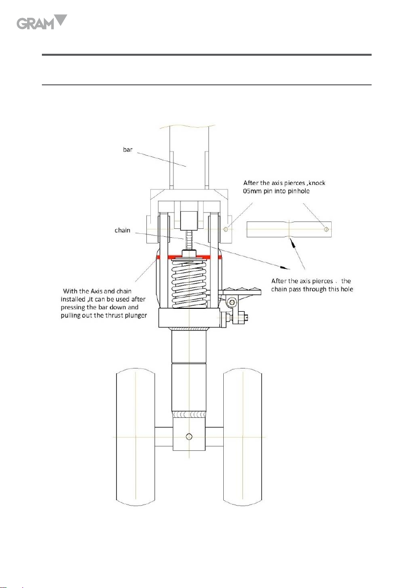
HANDLE ASSEMBLY
8
Page 9

REGULATION OF THE FINGERLIKE
Regulation of the fingerlike handle’s three positions (ascend, middle,
descend).
On the pallet truck, you will see the fingerlike handle, which can be operated
on three positions:
Ascend - Middle - Descend --
When the operation has been completed, the handle should be put on the
middle position. The position of the fingerlike handle has been adjusted
before leaving factory, and if you need to change it, please do as the following
steps:
• If you push the handle down in the “middle” position, the fork rises,
please turn the screw round unloading board clockwise until the fork
does not ascend when you press the handle.
• If you push the handle down in the “middle” position, the fork declines
please turn the screw round on the unloading board anti-clockwise until
the fork does not descend when you press the handle.
• With the fingerlike handle in the “descend” position, the fork does not
descend, please turn the screw round on the unloading board clockwise
until the fork descend with the handle on that position. Then according
to 3.1 and 3.2, Check the middle (running position)to ensure the screw in
the right position.
• With the fingerlike handle in the “ascend” position, the fork does not
rise, please turn the screw round on the unloading board anti-clockwise
until the fork ascend with the handle on that position.
9
Page 10

MAINTENANCE AND REPAIR
Refueling
Check oil every six months. Recommend using hydraulic oil: ISO VG32, at
400C its kinematic viscosity is 32 cSt, the total 0.3 liters.
Because of the transport or inversion, the air is likely to enter the hydraulic
pump, which will result in the fork not rising on the ascend position. The
following methods help exhaust. Move the handle from ascend position to
the descend position several times.
Routine maintenance and overhaul
Routine maintenance is essential .You should focus on wheels and mandrel
and timely remove the foreign body enwinding and pricking into the wheels.
When the removal has been completed, unload items on the fork, and
descend the fork to the lowest position.
Lubricants
In factories, all the bearings and axle have been applied the long life
lubricants; you just need to apply assemblies in a month of intermittent, or
each time a thorough overhaul.
Safety Guide
1. Operating the truck, one should read the operation manual and the
attentions on the truck carefully.
2. Keep in mind that before pulling the truck, raise the fork slightly.
10
Page 11

3. When pulling the truck, please keep the handle on the middle position.
So it is easy to move and reduce the rebound from the piston to handle.
Moreover it protects the liquid seal and piston components and extends
the service life of truck.
4. One without skilled training isn’t allowed to operate it.
5. nspect the truck including the wheels, handles, fork and rocker before
operating.
6. Do not operate it on the slantwise ground.
7. Do not carry man on the fork.
8. It’s better for the operator to dress protective gloves and shoes.
9. In the process of lifting and transporting cargo, all the workers concerned
should keep away from the fork at least 600 mm.
10. Pay attention to the focus of the objects, and avoid inclining and deviating
(see Figure 2 B).
11. Do not overload.
12. Operate it cautiously when in special circumstance and location.
Debugging method of the forklift scale
1. Disconnect the monitor’s plug.
2. Adjust every regulation resistance by digital multimeter “200 Ω” to make
the resistance “10 Ω”.
Debugging method: connect one pen of multimeter to “E +” of the “OUT”,
the other pen, respectively, to “E +” of A, B, C, D then connect the other
11
Page 12

pen, respectively, to “E-” of A, B, C, D. At last, with eight multimeter
debugged, disconnect multimeter.
3. Insert monitor’s plug then begin to demarcate.
4. After the demarcation, put “the weight on the front”, middle, and back of
the fork respectively to see whether the show value is the same, if not,
adjust slightly Group C and Group D on the wiring board, do as follows:
• If the value is wrong when put on the front of the fork, adjust “D +” of
Group D, clockwise for small and counterclockwise for large.
• If the value is wrong when put on the back of the fork, adjust “C +”
of Group C, clockwise for small and counterclockwise for large. Until
the value is the same.
Note: This adjustment method is available when there is little error, if not,
don’t use this method. You Should check whether the sensors are intact and
loose, make sure fork and fork legs are not rubbed and so on. Also when the
value is not accurate, adjust only C group and D group at the wiring board, or
A group and B group on the potentiometer, otherwise, it cannot be adjusted
correctly.
12
Page 13

STANDARD SPECIFICATIONS
Load 2000kg
Fork length 1150mm
Fork width 550mm/685mm
Fork height
≤ 80mm
Weight 95-105kg
TROUBLESHOOTING
No. Malfunction Cause Approach
Fork can’t ascend to
1
the maximum height.
Fork cannot be
2
raised.
-Inadequate hydraulic oil. - Refueling.
- No hydraulic oil.
- Impure oil.
- Keep bolts too close or
screws too tight so that
- Refueling.
- Change oil.
- Adjust bolts or
screws.
the valve remains open.
- There is air in the
Hydraulic oil.
- Vent the air.
13
Page 14

3 Fork cannot descend.
4 Oil spill.
Fork declines,
5
release valve does
not work.
When weighing the
show value on the
6
front is small and the
back big.
- Placing of the goods
one side or overloading
makes the Pistons or
the body of the pump
damaged.
- Fork keep the ascend
position for a very long
time, which makes the
Pistons exposed and rusty,
and blocks the Pistons’
moving.
- Bolt or screw is not on
the correct position.
- Aging or damaged seals.
- Some broken parts.
- The impure hydraulic oil
leads that the release
valve cannot close tightly.
- Some parts of the
hydraulic system
breakdown or damage.
- Air is mixed with oil.
- Seal aging or damaged
parts.
- Bolt or screw is not on
the correct position.
- A phenomena of plate
collision near the sensor
at the front of the fork.
Replacement the
pistons with big ones or
of the pump.
- Please lower the fork to
the minimum position
when unused and
lubricate the rod timely.
- Adjust the bolt or
screw.
- Update.
- Update.
- Change the oil.
- Check and replace waste
parts.
- Vent the air.
- Update.
- Adjust bolt or screw.
- Open the board to
check the collision, if
necessary, polish or
boost the sensor.
14
Page 15

When weighing the
show value on the
7
front is big and the
back small fork.
When weighing the
show value on the front
8
and back different from
each other.
- A phenomena of plate
collision near the sensor
at the back of the fork.
- Resistance on the
terminal board need to be
adjusted.
- Debug as Chapter VI of
the brochure “forklift
debugging method” and
recalibrate.
- Open the board to
check the collision, if
necessary, polish or
boost the sensor.
- A sensor fault.
- Recalibrate after
replacement of the
sensor.
INSTRUCTION FOR USE
1. Please keep the scale in a cool dry place. Do not store it at high
temperature.
2. Do not allow any liquids to come into contact with the scale. If necessary
wipe the scale with a dry soft clothe.
3. Avoid objects impacting with the scale. Do not drop loads onto the scale
or subject the weighing pan to any strong shock loads.
4. The load placed on the weigh pan must not exceed the maximum
weighing capacity of the scale.
5. If the scale is not going to be used for some time, please clean it and
store it in a plastic bag in dry conditions. A desiccant sachet may be
included to prevent any moisture build up.
15
Page 16

PREPARING TO USE THE SCALE
1. Avoid operating the scale in direct sunlight or drafts of any kind.
2. If possible avoid connecting the scale to ac power outlet sockets which
are adjacent to ther appliances to minimize the possibility of interference
affecting the performance of the scale.
3. Remove any weight that might be on the weigh pan before the scale is
switched on and avoid leaving weight on the pan for long periods of time
4. All goods weighed should be placed in the centre of the weigh pan for
accurate weighing. The overall dimensions of the goods being weighed
should not exceed the dimension of the weigh pan.
5. Once the scale has been powered on, it will go through an LCD display
test and it is ready for use when the display shows zero.
6. The scale requires about 15 minutes warm up before operation to ensure
best accuracy.
7. Please note when the battery symbol keeps on the screen, the batteries
need to be charged.
FEATURES AND SPECIFICATION OF INDICATOR
Features
• Large LED display (digit height 30mm x 13mm).
• Kilogram (kg), and pound (lb) weighing modes.
• Application include: simple counting , hold, accumulation.
16
Page 17
• Low power indication and auto power off.
Options:
• Serial printer
Specifications
Minimum 350 ohm load cells
Load Cells
Readability Selectable, 0.0
Tare Function Full
Units of measure Kg , lb
Power supply Rechargeable battery or Charger DC 7.2V 1A
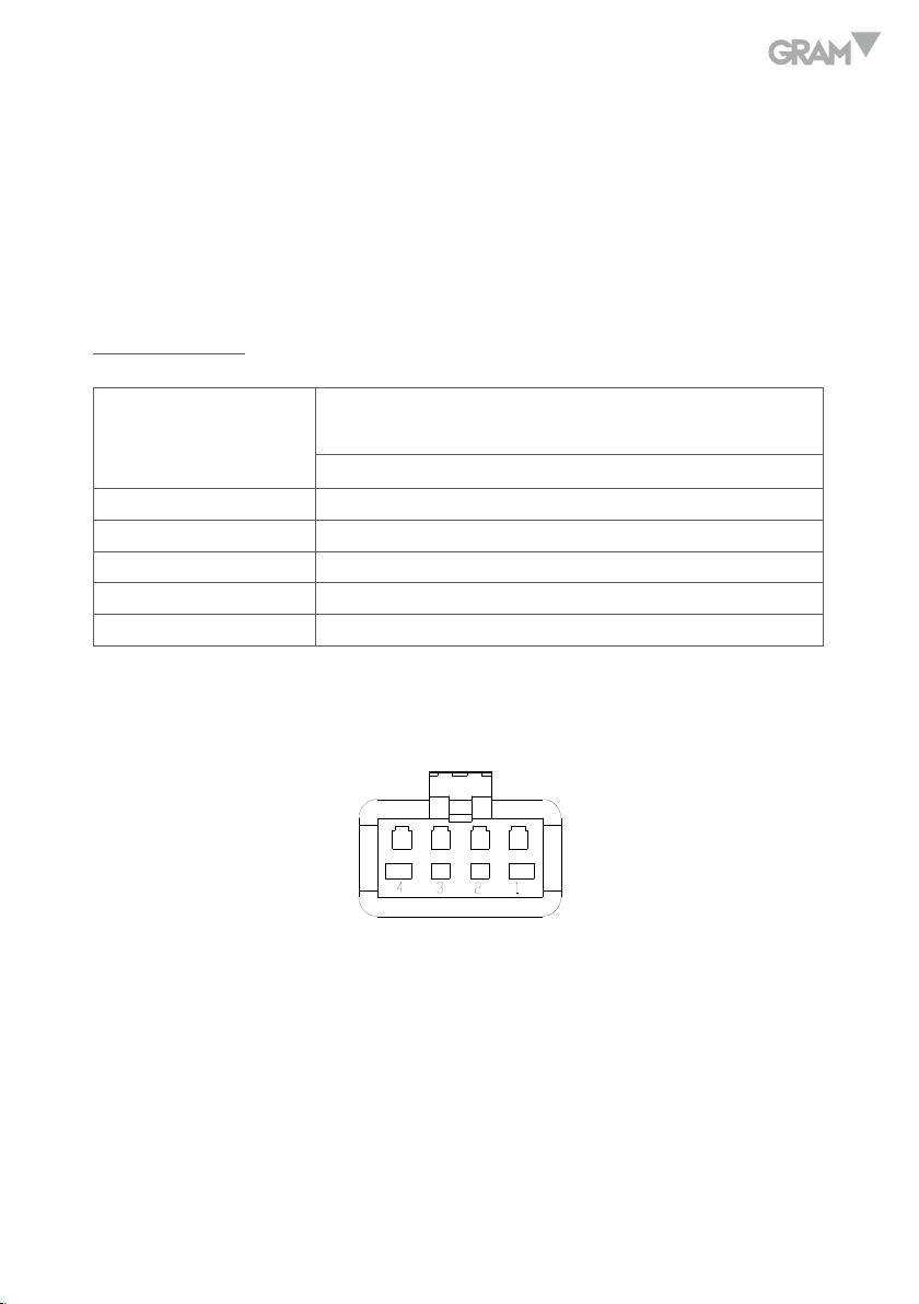
Connector 4 pin d socket
1. Load cell connection:
Maximum 1000 ohm
(Up to 4 load cells of 350 ohm)
Pin 1. Connects with EXC +
Pin 2. Connects with EXC -
Pin 3. Connects with SIG +
Pin 4. Connects with SIG -
17
Page 18
2. RS-232 connection:
2
5
2- pin. Data output (TXD)
5- pin. Ground (GND)
3. Printer connection:
Printer pin 1. Connects with +5V
Printer pin 2. Connects with GND
Printer pin 4. Connects with TXD
Printer pin 5. Connects with GND
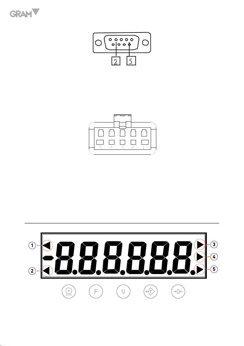
DISPLAY DESCRIPTION
18
Page 19

1. Zero status indication, Displayed when the scale is at the centre
of its zero band.
2. Tare status indication, Displayed when the weight has been tare.
3. Simple counting indication, Displayed when the scale is in simple
counting mode.
4. Unit indication, Displayed when the scale is in g or lb unit.
5. Kg indication, Displayed when the scale is in kg unit.
KEYPAD DESCRIPTION
ZERO key, in the menu use as “UP“ key. When the weigh pan is empty
(free of load) and the display is not showing zero, press the “ZERO” key to
zero the scale.(The weight can be zero is only at the 2% of Max. capacity).
TARE key, in the menu use as “RIGHT“ key. The tare function will not
operate during the following conditions:
• When the scale powers on if the weight is negative and after a
container is placed on the weigh pan if the weight is still below zero.
• The tare value is over the full scale capacity.
UNIT key. Use this key to switch between kg and g or lb units.
FUNCTION key. Use this key to choose the functions: Simple counting,
Check weighing, accumulation…
PRINT key, in the menu use as “confirm“ key. Use this key to print
data when the printer is connected.
19
Page 20
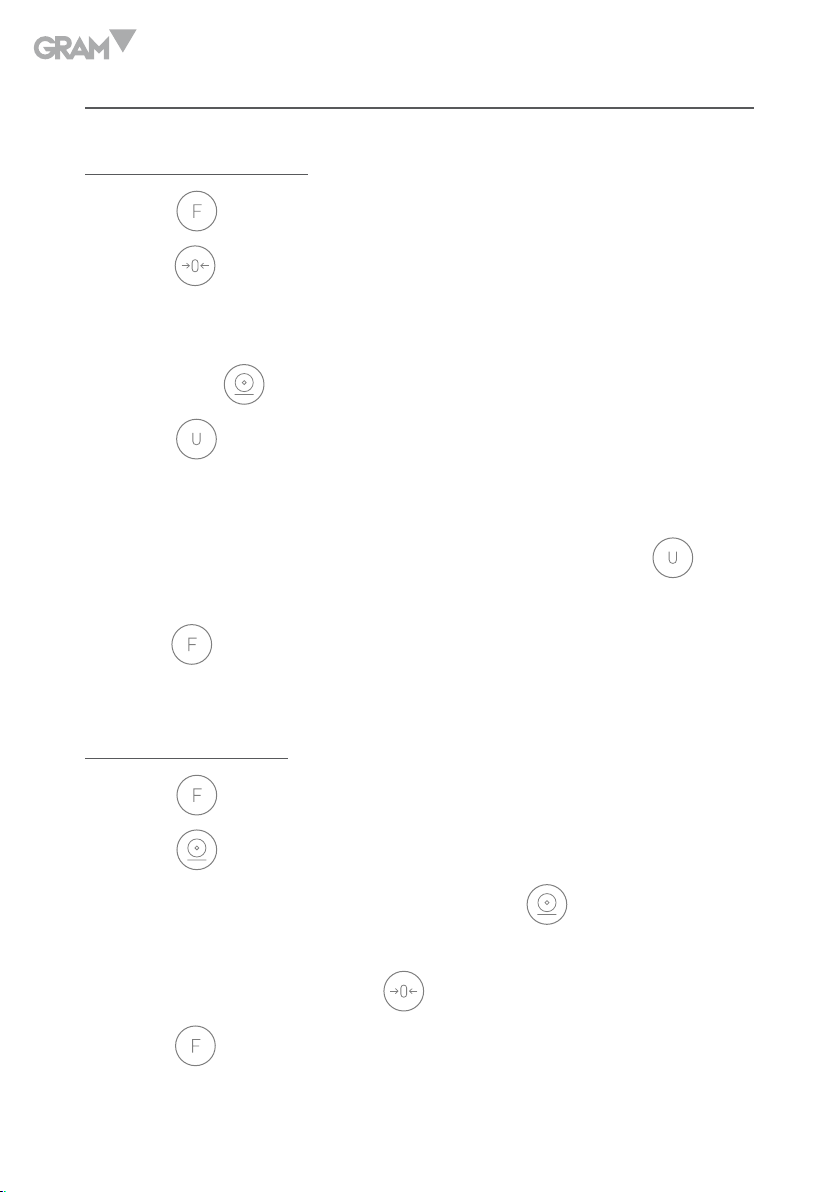
OPERATING THE SCALE
Simple Counting Mode
1. Press
2. Press
place the number of samples on the weighing pan. The number should
match the options for parts counting. i.e., 10, 20, 50, 100, 200 pieces.
3. Then press
4. Press
unit weight and shows total weight then back to simple counting mode.
5. After display shows unit weight and total weight the scale back to simple
counting mode, user can continue use this mode or press
return to weighing mode.
6. Press
key once, the display will show “PCS 10”.
key to choose sample numbers from 10, 20, 50 to 100 pcs, then
key to start the simple counting mode.
key to check the unit weight and total weight, LCD will shows
key to
key to exit simple counting mode and move back to weighing mode.
Hold Weighing Mode
1. Press
2. Press
3. When choose this mode, user needs to press
are put on pan and the scale is stable.
4. Take off the object and press
5. Press
20
key three times, the display will show “Hold”.
key to start the HOLD mode.
key to exit from HOLD mode and move back to weighing mode.
key after the objects
key the until back to zero.
Page 21

Accumulation Mode
1. Press
2. Press
key four times, the display will show “A C C“.
key to confirm.
Manual Accumulation
When choose this mode, user needs to press
put on pan and the scale is stable to accumulate the data; take off the object
and wait until zero, then put other object to continue accumulate data.
Press
accumulated weight; LCD will shows total accumulated numbers then shows
the total accumulated weight.
Scale will back to accumulation mode after shows the total accumulated
numbers and weight.
Press
key to overview the total accumulated numbers and total
key to exit accumulation mode and move back to weighing mode.
key after the objects are
POWER SELECTION
• 6V4Ah rechargeable battery
• 110V or 220V AC/DC adaptor
POWER CONSUMPTION
• Approximately DC 17mA (Scale)
21
Page 22

CHARGING THE BATTERY
• When the low battery symbol is on, it means the power of scale is low
needs to change the battery or plug-in the adaptor to recharge the battery.
• To the right of the display is a LED to indicate the status of battery
charging. When the scale is plugged into the mains power the internal
battery will be charged. If the LED is green the battery is being charged.
If it is red indicates the battery is increasing the charge level. Continue to
charge overnight for a complete re-charge.
ADVANCED FUNCTIONS
Checking battery voltage
When scale is on and at zero and stable, long press
seconds (beeper sounds) then release the key, LCD sill shows the battery
voltage for 3 seconds ten back to weighing mode.
key around 3-5
Auto Off setup
When scale is on and at zero and stable, long press
off setup, use
and back to weighing mode.
On. Enable (scale will turn off after 10 mins haven’t been use; to be
able to use the scale, needs to turn on the on/ff switch).
Off. Disable.
22
key to enable or disable, then press
key enter the auto
key to confirm
Page 23

DIVISION SETUP
When scale is on and at zero and stable, long press
division setup, use
key to select the divisions, then press
key enter the
key to
confirm and back to weighing mode.
TIME & DATE SETTING
Long pressing
press
key (Down) to check Year, Month, Date, Hour, Minute, Second etc.
At this time, press
exchanged.
1. Revising mode: When the time begins to flicker, change related data,
press
2. Checking mode: If the data not saved, the time will not change after back
to checking mode.
Data show as follows:
and
key to save the time and then back to checking mode.
keys together enter time checking mode, then
key, checking mode and revising mode can be
1. Clk 24/12: (clock) choose between 24-hour system and 12-hour system.
Press
key to make change.
2. APM A/P: (am pm) 12-hour system. “a” for “morning”, “p” for “afternoon.
Press
to make a change. In 24-hour system mode, it cannot be set,
showing ”—“.
3. YEA 00: (year) Input number for the accordingly year. “12” for “2012”. The
largest number is 99. Press
Press
key once, the other digit adds by “1”.
key once, the decimal digit adds by “1”.
4. Mon 00: (month) Input number for the accordingly month. “4” for April.
23
Page 24

The largest number is 12. Press
“1”. Press
key once, the other digit adds by “1”.
key once, the decimal digit adds by
5. Dte 00: (date ) Input number for the accordingly date. “15” for the 15th day
of a month. The largest number is 31. Press
digit adds by “1”. Press
key once, the other digit adds by “1”.
key once, the decimal
6. Hou 00: (hour) Input number for the accordingly hour. “8” for 8:00. In 12hour system, the largest number is 12. In 24-hour system, the largest
number is 23. Press
key once, the other digit adds by “1”.
key once, the decimal digit adds by “1”. Press
7. Min 00: (minute) Input number for the accordingly minute. “30” for 30
minutes. The largest number is 59. Press
key once, the decimal digit
adds by “1”. Press key once, the other digit adds by “1”.
8. Sec 00: (second) Input number for the accordingly second. “30” for 30
seconds. The largest number is 59. Press
adds by “1”. Press
key once, the other digit adds by “1”.
key once, the decimal digit
9. Day 00: (day) Input number for the accordingly day. “0” for 30 Sunday. ”1”
for Monday. The largest number is 6.
CALIBRATION
Setting up division, decimal point, max. capacity and calibration.
Press and hold
24
key, then turn on the scale to enter division setting:
Page 25

Division Setting
LCD shows [d x]. Then press
press
Ex. When display shows [d 5]. Press
enter the decimal point setting.
key to confirm and enter the decimal point setting.
key to select 1, 2, 5, 10, 20, 50, and then
key, the division set as 5, then
Decimal point setting
LCD shows [p x]. Then press
and then press
Ex. When display shows [p 0.000], press
then enter the maximum capacity setting.
key to confirm and enter the maximum capacity setting.
key to select 0, 0.0, 0.00, 0.000, 0.0000, P.00000,
key, the division set as 0.000,
Maximum capacity setting
LCD shows [ FULL ], around 2-3 seconds then LCD shows [000.000]. The
decimal point was set as 3 decimal points, then press
flashing digits to the right in circle to select the digits that will increase
the number, then press
appears, then repeat the above moves until LCD shows the maximum
capacity then press
key to increase the number until the number
key to enter calibration setting.
key to move the
Ex. LCD shows [50.000] then press
key to enter calibration setting.
Zero point calibration
LCD shows [CaL 0 ]. Do not put any objects on the pan when display shows
this, then scale will move to next calibration setting.
25
Page 26

Second point calibration (unit is in kg)
LCD shows [00.000]. The decimal point was set as 3 digits. (this depends on
what user sets in the last moves). Put on the weights on the pan which will
be calibrate as second point, then use
the right in circle to select the digits that will increase the number.
key to move the flashing digits to
Press
key to increase the number until the number appears, then repeat
the above moves until LCD shows the numbers which is equal to the weights
put on the pan, then wait until the scale is stable then press
key, scale
will move into the weighing mode then press “calibration” key to confirm
calibration finish.
26
Page 27

GUARANTEE
This balance is guaranteed for one year from the delivery date. The guarantee
covers any fabrication defect of the material.
During this period, GRAM PRECISION, SL, covers the manpower and the
spare parts costs necessary for the reparation of the scale.
This guarantee does not cover the failures caused by an inappropriate use
or overload.
The guarantee does not cover the freight cost (transport) necessary to
repair the balance.
27
Page 28

ESPAÑOL
Palanca
Unavezatravesadoeleje,
Cadena
Unavezinstaladoelejeyla
Unavezatravesadoeleje,la
MONTAJE DEL CONJUNTO DEL TIMÓN
colocarelpasadorde05mm
dentrodelagujero
cadena,sepuedeutilizar
despuésdepresionarlabarra
hacíaabajoytirandohacia
afueradelémbolodeempuje.
cadenapasaráatravésdeeste
agujero
28
Page 29

PALANCA DE REGULACIÓN
La palanca de regulación tiene tres posiciones (subir –reposo-bajar).
Subir - Reposo - Bajar --
Cuando no se utilice la transpaleta, el timón debe ser colocado en posición
reposo. La posición de la palanca de regulación ha sido ajustada en fábrica,
si se precisa cambiarla, seguir los siguientes pasos:
• Si se empuja la palanca hacía abajo en posición reposo, las horquillas se
elevan, girar el tornillo de descarga en el sentido de las agujas del reloj, las
horquillas no se elevarán cuando se presione la palanca.
• Si se empuja la palanca hacía abajo en posición reposo, las horquillas
descenderán, girar el tornillo de descarga en el sentido contrario de las agujas
del reloj hasta que las horquillas no desciendan al presionar la palanca.
• Con la palanca de regulación en posición “bajar”, las horquillas no descienden,
girar el tornillo de descarga en el sentido de las agujas del reloj hasta que las
horquillas desciendan al presionar la palanca. De acuerdo con los apartados
3.1 y 3.2, comprobar el centro (posición de funcionamiento) para garantizar
que el tornillo está en la posición correcta.
• Con la palanca de regulación en posición “subir”, las horquillas no se
elevarán, girar el tornillo de descarga en sentido contrario a las agujas del
reloj hasta que las horquillas se eleven con la palanca en esta posición.
29
Page 30

REPARACIÓN Y MANTENIMIENTO
Comprobación nivel del aceite hidráulico
Comprobar el aceite cada 6 meses. Recomendamos utilizar aceite hidráulico: ISO
VG32, a 400C su viscosidad cinemática es de 32 cSt, Capacidad total, 0.3 litros.
Debido al transporte, es probable que entre aire en la bomba hidráulica,
lo cual puede provocar que las horquillas no se eleven en la posición de
ascenso. El siguiente método puede ayudar a evitarlo: Mover la palanca
desde la posición de “subir” a la posición de “bajar” varias veces.
Rutina de mantenimiento y revision
La rutina de mantenimiento es esencial. Usted debe centrarse en las ruedas
y en el mandril, retirar los cuerpos extraños que se ubiquen en las ruedas
y evitar que éstas se pinchen. Cuando las ruedas queden libres de suciedad
y cuerpos extraños, retirar la carga y descender las horquillas hasta la
posición más baja.
Lubricantes
En fábrica se han aplicado lubricantes de larga vida tanto en los rodamientos
como en el eje, usted solo necesita aplicar lubricante periódicamente (cada
mes) o cada vez que se realice una revisión a fondo.
Guia de seguridad
1. Antes de utilizar la transpaleta, leer detenidamente este manual de
instrucciones.
30
Page 31

2. Tener en cuenta que antes de desplazar el transpalet, se deberá levantar
un poco las horquillas.
3. Al desplazar el transpalet, por favor, mantener la palanca en posición
media. De esta manera, resultará más fácil de mover y se reducirán
los rebotes del pistón de la palanca. Además, también se protegerá el
precinto del líquido y los componentes del pistón, todo ello, alarga la
vida útil de la transpaleta.
4. El transpalet debe ser utilizado por personal con formación cualificada.
5. Antes de utilizar el transpalet, inspeccionar las ruedas, palancas y horquillas.
6. No utilizar la transpaleta sobre superficies oblicuas.
7. No transportar a una persona sobre la horquilla.
8. Se recomienda que el operador lleve guantes y calzado de seguridad.
9. En el proceso de elevación y transporte de carga, todos los trabajadores de
alrededor deben mantenerse alejados de las horquillas al menos 600 mm.
10. Prestar mucha atención en el modo de cargar el palet y evitar la
inclinación y desviación de la carga (ver figura 2 B).
11. No exceder la capacidad maxima del transpalet.
12. Utilizar el transpalet con precaución en circunstancias y ubicaciones especiales.
Método de ajuste del transpalet
1. Desconectar el enchufe del indicador.
2. Ajustar el multímetro digital en la escala de “200 Ω” para medir la
31
Page 32

resistencia de cada grupo a “10 Ω”.
Método de ajuste:
1. Conectar una punta del multímetro a “E+” y con la otra punta comprobar
cada grupo del “E +” A, B, C y D ajustar todos los grupos a “10 Ω”. Ahora
conectar una punta del multímetro a “E-“ y con la otra punta comprobar
cada grupo del “E-“ A, B, C y D. Al menos efectuar ocho medidas y
finalmente desconectar el multímetro.
2. Insertar el enchufe del indicador y conectarlo.
3. Colocar el peso en la parte frontal, en medio y en la parte trasera de
las horquillas, comprobar que el valor del peso es el mismo, si no lo es,
ajustar ligeramente los Grupos C y D de la placa de circuito:
• Si el valor es incorrecto cuando la carga se coloca en la parte frontal
de la horquilla, ajustar “D +” del grupo D, en sentido a las agujas
del reloj para variaciones pequeñas y en sentido contrario para
variaciones más grandes.
• Si el valor es incorrecto cuando la carga se coloca en la parte trasera
de la horquilla, ajustar “C +” del grupo C, en sentido a las agujas
del reloj para variaciones pequeñas y en sentido contrario para
variaciones más grandes.
Nota: Este procedimiento de ajuste es factible solo cuando el error es
pequeño, de lo contrario, no utilizar este método.
Comprobar que las células de carga estén intactas y sueltas, asegurarse que
las horquillas no se rozan. También, cuando el valor no es exacto, ajustar
únicamente los grupos C y D de la placa o los grupos A y B del potenciometro,
de lo contrario, no se podrá ajustar el transpaleta correctamente.
32
Page 33

ESPECIFICACIONES DEL TRANSPALET
Capacidad máxima 2000kg
Longitud de la horquilla 1150mm
Ancho de la horquilla 550mm/685mm
Altura de la horquilla
Peso 95-105kg
≤ 80mm
33
Page 34

SOLUCIÓN DE PROBLEMAS
No. Problema Causa Acción
La horquilla no
1
puede elevarse hasta
la altura máxima.
La horquilla no se
2
eleva.
La horquilla no
3
puede descender.
- Aceite hidráulico
inadecuado.
- Falta de aceite
hidráulico.
- Aceite sucio.
- Mantener los pernos
demasiado cerca o
demasiado apretados los
tornillos, de manera que
la válvula permanezca
abierta.
- Hay aire en la bomba
hidráulica.
- La colocación de la
mercancía en un solo
lado ó la sobrecarga,
provoca que los pistons
o el cuerpo de la bomba
hidráulica se dañen.
- Las horquillas han estado
durante un largo periodo
de tiempo elevadas, lo
que ha provocado que los
bloques de movimiento
de los pistones se han
oxidado.
- El perno o tornillo no está
en la posición correcta.
- Revisar nivel de
aceite.
- Revisar nivel de
aceite.
- Cambiar el aceite.
- Ajustar los pernos o
los tornillos.
- Extraer el aire.
- Reemplazar los
pistones por unos más
grandes.
- Bajar la horquilla a la
posición minima
cuando no se utilice y
lubricar la varilla.
- Ajustar el perno o
tornillo.
34
Page 35

4 Derrame de aceite.
La válvula de
5
descarga no funciona.
- Envejecimiento o
desperfectos en los
precintos.
- Algunas piezas rotas.
- El aceite sucio
provoca que la válvula
no pueda cerrarse
herméticamente.
- Alguna pieza del
sistema hidráulico está
dañada o rota.
- El aire se ha mezclado
con el aceite.
- Precinto envejecido o
piezas dañadas.
- El perno o tornillo no
está en la posición
correcta.
- Actualizar.
- Actualizar.
- Cambiar el aceite.
- Revisar y reemplazar
las piezas gastadas.
- Extraer el aire.
- Actualizar.
- Ajustar el perno o
tornillo.
INSTRUCCIONES DE UTILIZACIÓN
1. Mantener el transpalet en un lugar frio y seco. No almacenarlo en
ambientes con altas temperaturas.
2. Evitar que ningún objeto impacte contra el transpalet. No deje caer
objetos sobre la horquilla y evitar choques fuertes.
3. La carga situada sobre la horquilla no debe exceder la capacidad
máxima del transpalet.
4. Si el transpalet no va a ser utilizado durante un periodo de tiempo,
límpielo y cúbralo con una bolsa de plástico en un ambiente seco. Una
35
Page 36

bolsita desecante se puede incluir para prevenir cualquier acumulación
de humedad.
PREPARACIÓN DEL TRANSPALET PARA SU UTILIZACIÓN
1. Evitar los rayos directos del sol y cualquier tipo de corriente de aire.
2. Si es posible, evitar conectar el transpalet a una toma de corriente
alterna adyacente, para reducir al máximo interferencias alejarlo de
otros aparatos eléctricos.
3. Antes de conectar el transpalet, asegurarse de que no hay ningún objeto
sobre la horquilla.
4. No dejar ningún objeto sobre la horquilla durante un largo periodo de
tiempo, esto puede dañar las células de carga.
5. Todos los productos a pesar, deben ser colocados en el centro de la
horquilla para obtener unos resultados más precisos.
6. Las dimensiones totales de las mercancías no deben exceder la
dimensión de la horquilla.
7. Una vez conectado el transpalet, el display efecturará un auto-test, a su
finalización la lectura quedará a cero y preparado para pesar.
8. Cuando el símbolo de la batería aparece en el display, significa que la
batería necesita ser cargada.
36
Page 37

ESPECIFICACIONES DEL INDICADOR
• Gran display de LED (altura del dígito 30mm x 13mm).
• Unidades de pesada: Kilogram (kg) y libras (lb).
• Funciones: cuentapiezas, hold y acumulación de pesadas.
• Indicador de batería baja.
• Autodesconexión.
Opciones:
• Impresora
CONECTORES
1. Conector célula de carga
Pin 1. Conecta con EXC+
Pin 2. Conecta con EXC-
Pin 3. Contecta con SIG+
Pin 4. Conecta con SIG-
37
Page 38

2. Conector RS-232
2
5
2- pin. Salida de datos (TXD)
5- pin. Ground (GND)
3. Conector impresora
Pin 1. conecta con +5V
Pin 2. conecta con GND
Pin 3. conecta con TXD
Pin 4. conecta con GND
DESCRIPCIÓN DEL DISPLAY
38
Page 39

1. Indicador de cero.
2. Indicador de tara.
3. Indicador de cuentapiezas.
4. Indicador de lb
5. Indicador de Kg.
DESCRIPCIÓN DE LAS TECLAS
Tecla CERO, en el menu de programación utilizar para desplazarse
hacia arriba. Cuando en la horquilla no haya peso y la lectura del
display no sea de cero, pulsar esta tecla para corregir dicha desviación
(rango: 2% de la capacidad máxima).
Tecla TARA, en el menu de programación utilizarla para desplazarse
hacia la derecha. La función de Tara no está disponible en las
siguientes condiciones:
• Cuando el transpalet se conecta y el valor del display es negativo.
• Cuando se ha sustraido el peso de un recipiente y la lectura del
display es de cero.
• Cuando el valor de la tara excede la capacidad máxima.
Tecla UNIDAD. Pulsarla para seleccionar la unidad de pesada
deseada, kg, g o lb.
Tecla FUNCION. Pulsar esta tecla para acceder a las funciones:
cuentapiezas, acumulación de pesadas….
Tecla PRINT, en el menu de programación utilizarla como tecla
de confirmación. Pulsar esta tecla para transmitir los datos a una
impresora (opcional).
39
Page 40

UTILIZACIÓN DEL TRANSPALET
Función cuentapiezas
1. Pulsar la tecla , el display mostrará “PCS 10”.
2. Pulsar la tecla
a 100 pcs, colocar sobre la horquilla el número de piezas seleccionado.
3. Pulsar la tecla
4. Pulsar la tecla
5. Pulsar la tecla
normal de pesaje.
para seleccionar el número de la muestra 10, 20, 50
para comenzar el conteo de piezas.
, el display mostrará el peso unitario y el peso total.
para salir del modo cuentapiezas y volver al modo
Función Hold
1. Pulsar la tecla
2. Pulsar la tecla
3. Colocar el objeto sobre la horquilla y cuando el peso quede estable
pulsar la tecla
4. Retirar el objeto y pulsar la tecla
tres veces, el display mostrará “Hold”.
para acceder al modo HOLD.
.
hasta que la lectura quede a cero.
5. Pulsar la tecla
de pesaje.
40
para salir del modo Hold y volver al modo normal
Page 41

Acumulación de pesadas
1. Pulsar la tecla
2. Pulsar la tecla
cuatro veces, el display mostrará “A C C “.
para confirmar.
Acumulación manual
Colocar el objeto sobre la horquilla, cuando el peso quede estable pulsar la tecla
para memorizar su peso, retirar el objeto y esperar a que la lectura del display
quede a cero, colocar otro objeto para continuar con la acumulación de pesadas.
Pulsar la tecla
peso total acumulado.
Pulsar la tecla
para visualizar el número de acumulaciones efectuadas y el
para salir del modo acumulación y volver al modo normal de pesaje.
ALIMENTACIÓN
• Batería recargable 6V4Ah
• Alimentador 110V o 220V AC/DC
CONSUMO
• Aproximadamente DC 17mA.
• Aproximadamente DC 37mA con la iluminación del display.
41
Page 42

CARGA DE LA BATERÍA
• Cuando aparece el símbolo de batería baja en el display, significa que la batería
necesita ser cargada, conectar el alimentador a la red para efectuar la recarga.
• En la parte derecha del display aparecerá un LED indicando el estado de la
carga. Si el LED es de color verde significa que la batería empieza a cargarse,
si es de color rojo significa que el nivel de la batería está aumentando, esperar
hasta una recarga completa.
FUNCIONES AVANZADAS
Comprobación del voltaje de la batería
Con el display a cero, pulsar la tecla
tecla en el momento que el indicador emita una señal acústica. El display
mostrará el voltaje de la batería durante 3 segundos y v volverá al modo
normal de pesaje.
durante 3-5 segundos, soltar la
Autodesconexión
Con el display a cero, mantener pulsada la tecla
parámetro, pulsar la tecla
Pulsar la tecla
On. El transpalet se desconectará automáticamente después de 10
minutos sin ser utilizado.
Off. Función desactivada.
para confirmar y volver al modo normal de pesaje.
para activar o desactivar la función.
para acceder al
42
Page 43

CONFIGURACIÓN DE LA DIVISIÓN (manual técnico)
Con el display a cero, mantener pulsada la tecla
parámetro, pulsar la tecla
Pulsar la tecla
para confirmar y volver al modo normal de pesaje.
para seleccionar las divisiones.
para acceder al
CONFIGURACIÓN DE LA FECHA Y HORA
Mantener pulsadas al mismo tiempo las teclas
parámetro.
Pulsar la tecla
En este momento, pulsar la tecla
para visualizar el Año, Mes, Día, Hora, Minuto, Segundo, etc.
, para acceder a los modos de
comprobación y modificación.
1. Modo modificación: Cuando la hora empieza a parpadear, cambiar los
datos y pulsar la tecla
para guardar los cambios y pasar al modo
de comprobación.
y
para acceder al
Los datos se muestran así:
1. Clk 24/12: (reloj) elegir entre el sistema 24-horas o el sistema 12-horas.
Pulsar la tecla
para cambiar los datos.
2. APM A/P: (am pm) sistema 12-horas. “a” para mañana, “p” para la tarde.
Pulsar la tecla
para cambiar los datos. En el sistema 24-horas, no
se puede cambiar, mostrando ”—“.
3. YEA 00: (año) Introducir el número “12” para “2012”. El número mayor
es 99. Pulsar la tecla
, el dígito decimal se añade por “1”. Pulsar la
tecla , el otro dígito se añade por “1”.
43
Page 44

4. Mon 00: (mes) Introducir el mes, “4” para Abril. El número mayor es 12.
Pulsar la tecla , el dígito decimal se añade por “1”. Pulsar la tecla
, el otro dígito se añade por “1”.
5. Dte 00: (día) Introducir el número del día. El número mayor es 31. Pulsar
la tecla
, el dígito decimal se añade por “1”. Pulsar la tecla , el
otros dígito se añade por “1”.
6. Hou 00: (hora) Introducir la hora, “8” para las 8:00. En el sistema
12-horas, el número mayor es 12. En el sistema 24-horas, el número
mayor es 23. Pulsar la tecla
, el dígito decimal se añade por “1”.
Pulsar la tecla , el otro dígitos se añade por “1”.
7. Min 00: (minuto) Introducir el minuto, “30” para 30 minutos. El número
mayor es 59. Pulsar la tecla
, el dígito decimal se añade por “1”.
Pulsar la tecla , el otro dígito se añade por “1”.
8. Sec 00: (segundo) Introducir el segundo, “30” para 30 segundos. El
número mayor es 59. Pulsar la tecla
, el dígito decimal se añade por
“1”. Pulsar la tecla , el otro dígito se añade por “1”.
9. Day 00: (día) Introducir el número del día, “0” para Domingo, ”1” para
Lunes…El número mayor es 6.
CALIBRACIÓN (manual Técnico)
Ajuste de la division, punto decimal, capacidad maxima y calibración.
Con el indicador apagado, mantener pulsada la tecla
pulsar la tecla de encendido.
44
y sin soltarla
Page 45

Configuración de la división
El display muestra [d x], pulsar la tecla
Pulsar la tecla
(configuración del punto decimal).
para confirmar y pasar al siguiente parámetro
para seleccionar 1, 2, 5, 10, 20, 50.
Configuración del punto decimal
El display muestra [p x], pulsar la tecla
0.00, 0.000, 0.0000, P.00000. Pulsar la tecla
siguiente parámetro (configuración de la capacidad máxima).
para seleccionar 0, 0.0,
para confirmar y pasar al
Configuración de la capacidad máxima
El display muestra [ FULL ] durante 2-3 segundos, seguidamente muestra
[000.000], (punto decimal configurado a 3 puntos), pulsar la tecla
mover los dígitos parpadeantes hacía la derecha, utilizar la tecla
incrementar el número.
para
para
Una vez introducido el valor de la capacidad máxima, pulsar la tecla
para confirmar y pasar al siguiente parámetro (calibración).
Calibración del punto de cero
El display muestra [CaL 0 ], no colocar ningún objeto sobre la horquilla
cuando el display muestre este mensaje, seguidamente la balanza pasará al
siguiente parámetro de calibración.
45
Page 46

Calibración del Segundo punto (unidad de pesada kg)
El display muestra [00.000] (el punto decimal se configuró a 3 dígitos).
Colocar la(s) pesa(s) de calibración sobre la horquilla, pulsar la tecla
para desplazarse de un dígito a otro y pulsar la tecla
el valor de cada dígito.
El valor introducido debe corresponder con el valor de las pesas colocadas
sobre la horquilla.
para incrementar
Pulsar la tecla
automáticamente.
para confirmar, el transpalet se calibrará
46
Page 47

GARANTÍA
Esta balanza está garantizada contra todo defecto de fabricación y de
material, por un periodo de 1 año a partir de la fecha de entrega.
Durante este periodo, GRAM PRECISION, SL, se hará cargo de la reparación
de la balanza.
Esta garantía no incluye los daños ocasionados por uso indebido o
sobrecargas.
La garantía no cubre los gastos de envío (portes) necesarios para la
reparación de la balanza.
47
Page 48

FRANÇAIS
Levier
Unefoisl’axepercé,placerla
Chaîne
Unefoisl’axeetlachaîne
Unefoisl’axepercé,lachaine
MONTAGE DE LA BARRE DE DIRECTION
brochede5mmdansletrou.
installés,ilpeutêtreutilisé
aprèsavoirtirésurlabarre
jusqu’enbasetentiranten
dehorslevérin.
peutpasseràtraversletrou.
48
Page 49

LEVIER DE RÉGULATION
Le levier de régulation peut occuper trois positions (Elévation – repos – descente).
Elévation - Repos - Descente --
Quand le transpalette n’est pas utilisé, la barre de direction doit être placée
en position repos. La position du levier de régulation a été réglée à l’usine, si
une modification est nécessaire, suivez les étapes suivantes:
• Si le levier est poussé vers le bas en position repos, les fourches se
soulèvent, faites tourner la vis de décharge dans le sens des aiguilles
d’une montre, les fourches ne se soulèveront pas lorsque vous appuierez
sur le levier.
• Si le levier est poussé vers le bas en position repos, les fourches
descendent, faites tourner la vis de décharge dans le sens contraire des
aiguilles d’une montre jusqu’à ce que les fourches ne descendent plus
en appuyant sur le levier.
• Avec le levier en position “descente”, les fourches ne descendent pas,
faites tourner la vis de décharge dans le sens des aiguilles d’une montre
jusqu’à ce que les fourches descendent en appuyant sur le levier.
Conformément aux paragraphes 3.1 y 3.2, vérifier le centre (position de
fonctionnement) pour garantir que la vis est bien positionnée.
• Avec le levier de régulation en position “montée”, les fourches ne se
soulèvent pas, faites tourner la vis de décharge dans le sens contraire
des aiguilles d’une montre jusqu’à ce que les fourches se soulèvent avec
le levier dans cette position.
49
Page 50

RÉPARATION ET MAINTENANCE
Vérification du niveau d’huile hydraulique
Vérifier l’huile tous les 6 mois. Nous vous recommandons d’utiliser de
l’huile hydraulique : ISO VG32, à 400C sa viscosité cinématique est de 32
cSt, Capacité totale, 0.3 litres.
En raison du transport, il est possible que de l’air entre dans la pompe
hydraulique, ce qui peut entrainer que les fourches ne se soulèvent pas
dans la position d’élévation. La méthode suivante peut permettre de l’éviter:
déplacez le levier de la position “Elévation” à la position “descente”
plusieurs fois.
Fréquence de maintenance et révision
Une maintenance fréquente est essentielle. Vous devez vous concentrer
principalement sur les roues et l’axe, retirer les corps étrangers qui se
trouvent dans les roues pour éviter que celles-ci se bloquent. Quand les
roues sont nettoyées, retirer la charge et descendre les fourches jusqu’à la
position la plus basse.
Lubrifiants
A l’usine des lubrifiants ont été appliqués de longue durée de vie sur
les roulements ainsi que sur l’axe, vous devez seulement appliquer le
lubrifiant périodiquement (chaque fois) ou chaque fois que vous réalisez
une révision complète.
50
Page 51

Guide de sécurité
1. Avant d’utiliser le transpalette, lire attentivement ce manuel d’instructions.
2. Prendre en compte qu’avant de déplacer le transpalette, il vous faudra
soulever un peu les fourches.
3. En déplaçant le transpalette, maintenir le levier en position repos. De
cette manière, ce sera plus facile pour le déplacer et cela permettra
aussi de réduire les rebonds du piston du levier. De plus, le joint du
liquide et les composants du piston seront également protégés. Tout
cela permettra de prolonger la durée de vie du transpalette.
4. Le transpalette doit être utilisé par des personnes ayant une formation
professionnelle.
5. Avant d’utiliser le transpalette, vérifier les roues, le levier et les fourches.
6. Ne pas utiliser le transpalette sur des superficies obliques.
7. Ne pas transporter une personne sur les fourches.
8. Il est recommandé que l’utilisateur porte des gants et des chaussures
de sécurité.
9. Pendant le processus d’élévation et le transport de charge, tous les
travailleurs doivent se tenir éloignés des fourches (au moins à 60cm).
10. Prêtez beaucoup d’attention au mode de chargement de la palette et
évitez l’inclinaison et la déviation de la charge (voir figure 2B).
11. Ne pas dépasser la capacité maximale du transpalette.
12. Utiliser le transpalette avec précaution dans les circonstances et les
lieux spéciaux.
51
Page 52

Méthode de réglage du transpalette
1. Débrancher la prise de l’indicateur.
2. Ajuster le multimètre digital à “200 Ω” pour mesurer la résistance de
chaque groupe à “10 Ω”.
Méthode de réglage:
Connecter une pointe du multimètre à “E+” et avec l’autre pointe vérifier
chaque groupe de “E +” A, B, C et D et ajuster tous les groupes à “10 Ω”.
Maintenant connecter une pointe du multimètre à “E-“ et avec l’autre pointe
vérifier chaque groupe de “E-“ A, B, C y D. Effectuer au moins huit mesures
puis déconnecter le multimètre.
1. Introduire la prise de l’indicateur et le connecter.
2. Placer le poids sur la partie avant, au milieu puis sur la partie arrière
des fourches, vérifier que la valeur du poids est la même, si ce n’est pas
le cas, ajuster légèrement les groupes C y D de la boîte de jonction:
• Si la valeur est incorrecte quand la charge est placée sur la partie
avant des fourches, ajuster “D +” du groupe D, dans le sens des
aiguilles d’une montre pour des petites variations et dans le sens
inverse pour des variations plus importantes.
• Si la valeur est incorrecte quand la charge est placée sur la partie
arrière des fourches, ajuster “C +” du groupe C, dans le sens des
aiguilles d’une montre pour des petites variations et dans le sens
inverse pour des variations plus importantes.
Note: Cette procédure de réglage est possible seulement quand l’erreur est
petite, dans le cas contraire ne pas utiliser cette méthode.
Vérifier que les cellules de charge sont intactes et libres, s’assurer que les
52
Page 53

fourches ne frottent pas. De plus, quand la valeur n’est pas exacte, ajuster
seulement les groupes C et D de carte ou les groupes A et B du potentiomètre,
dans le cas contraire, le transpalette ne pourra pas être ajusté correctement.
SPECIFICITÉS DU TRANSPALETTE
Capacité maximale 2000kg
Longueur des fourches 1150mm
Largeur des fourches 550mm/685mm
Hauteur des fourches
Poids 95-105kg
≤ 80mm
53
Page 54

RESOLUTION DE PROBLÉMES
No. Probléme Cause Action
Les fourches ne se
1
lèvent pas jusqu’à la
hauteur maximale.
Les fourches ne se
2
lèvent pas.
Les fourches
3
ne peuvent pas
descendre.
- Huile hydraulique
inadaptée.
- Manque d’huile
hydraulique.
- Huile sale.
- Les boulons ont été
gardés trop proches ou
les vis trop serrées de
telle sorte que la vanne
reste ouverte.
- Il y a de l’air dans le vérin.
- Le placement de
la marchandise
d’un seul côté ou la
surcharge, provoque
l’endommagement des
pistons ou du corps de la
pompe hydraulique.
- Les fourches ont été
relevées pendant un
long laps de temps, ce
qui a provoqué ce qui a
provoqué une oxydation
des blocs de mouvement.
- Le boulon ou la vis
n’est pas dans la bonne
position.
- Vérifier le niveau
d’huile.
- Vérifier le niveau
d’huile.
- Changer l’huile.
- Ajuster les boulons ou
les vis.
- Extraire l’air.
- Remplacer les pistons
par d’autres plus
grands.
- Descendre les fourches
jusqu’à la position la
plus basse quand vous
ne l’utilisez pas et
graisser la barre.
- Régler le boulon ou la
vis.
54
Page 55

- Vieillissement ou
endommagement des
4 Déversements d’huile.
La soupape de
5
décharge ne
fonctionne pas.
joints.
- Certaines pièces
endommagées.
- L’huile sale empêche
la vanne de se fermer
hermétiquement.
- Une pièce du système
hydraulique est cassée
ou endommagée.
- L’air s’est mélangé à l’huile.
- Joint endommagé ou
pièces cassées.
- Le boulon ou la vis n’est pas
dans la bonne position.
INSTRUCTIONS D’UTILISATION
- Mettre à jour.
- Mettre à jour.
- Changer l’huile.
- Contrôler et
remplacer les pièces
usées.
- Extraire l’air.
- Mettre à jour.
- Régler le boulon ou
la vis.
1. Maintenir le transpalette dans un lieu froid et sec. Ne pas le stocker
dans des milieux de hautes températures.
2. Éviter qu’un objet heurte le transpalette. Ne pas laisser tomber d’objets
sur les fourches et éviter les chocs importants.
3. La charge située sur les fourches ne doit pas excéder la capacité
maximale du transpalette.
4. Si le transpalette ne va pas être utilisé pendant une longue période,
le laver et le couvrir d’un plastique dans un endroit sec. Un sachet
déshydratant peut être inclus pour éviter toute accumulation d’humidité.
55
Page 56

PREPARATION DU TRANSPALETTE POUR UTILISATION
1. Éviter les rayons directs du soleil et les courants d’air.
2. Dans la mesure du possible, éviter de connecter le transpalette à une
prise de courant adjacente pour réduire au maximum les interférences
des autres appareils électriques.
3. Avant de connecter le transpalette, s’assurer qu’il n’y ait aucun objet sur
les fourches.
4. Ne laisser aucun objet sur les fourches pendant une longue période,
cela pourrait endommager les capteurs de pesées.
5. Tous les produits à peser doivent être placés au centre des fourches
pour obtenir des résultats plus précis.
6. Les dimensions totales des produits ne doivent pas dépasser la
dimension des fourches.
7. Une fois connecté au transpalette, l’écran effectuera un auto-test. A la
fin il indiquera zéro et sera prêt à l’utilisation.
8. Quand le symbole de la batterie apparaît à l’écran, cela signifie qu’il faut
la charger.
SPÉCIFICITÉS DE L’INDICATEUR
• Grand écran LED (dimensions des chiffres : 30mm x 13mm).
• Unités de pesée: Kilogrammes (kg) y livres (lb).
• Fonctions: compte-pièces, hold et accumulation de pesée.
56
Page 57

• Indicateur de batterie faible.
2
5
• Déconnexion automatique.
Options:
• Imprimante
CONNEXIONS
1. Connexion capteurs de pesées
Pin 1. connecté avec EXC+
Pin 2. connecté avec EXC-
Pin 3. connecté avec SIG+
Pin 4. connecté avec SIG-
2. Connexion RS-232
2- pin. Sortie de données (TXD)
5- pin. Ground (GND)
57
Page 58

3. Connexion imprimante
Pin 1. connecté avec +5V
Pin 2. connecté avec GND
Pin 3. connecté avec TXD
Pin 4. connecté avec GND
DESCRIPTION DE L’ÉCRAN
1. Indicateur du zéro.
2. Indicateur de tare.
3. Indicateur de compte-pièces.
4. Indicateur de livres (lb).
5. Indicateur de kilogrammes (kg).
58
Page 59

DESCRIPTION DES TOUCHES
Touche ZÉRO. Dans le menu de programmation, utiliser cette touche
pour se déplacer jusqu’en haut. Quand il n’y a pas de poids sur les
fourches et que l’écran n’affiche pas zéro, appuyer sur cette touche
pour corriger cette erreur (rang : 2% de la capacité maximale).
Touche TARE. Dans le menu de programmation, utiliser la touche
TARE pour se déplacer sur la droite. La fonction de tare n’est pas
disponible dans les conditions suivantes:
• Quand le transpalette se connecte et que la valeur à l’écran est
négative.
• Quand le poids d’un récipient a été soustrait et que l’écran affiche zéro.
• Quand la valeur de la tare dépasse la capacité maximale.
Touche UNITÉ. Appuyer sur cette touche pour sélectionner l’unité de
pesée souhaitée kg, g o lb.
Touche FONCTION. Appuyer sur cette touche pour accéder aux
fonctions suivantes: compte-pièce, accumulation de pesées.
Touche PRINT. Dans le menu de programmation, utiliser cette
touche comme touche de confirmation. Appuyer cette touche pour
transmettre les données à une imprimante. (Optionnel).
59
Page 60

UTILISATION DU TRANSPALETTE
Fonction Compte-pièces
1. Appuyer sur la touche , l’écran affichera “PCS 10”.
2. Appuyer sur la touche
10, 20, 50 à 100 pièces, placer sur les fourches le numéro de pièces
sélectionné.
3. Appuyer sur la touche
4. Appuyer sur la touche
5. Appuyer sur la touche
retourner au mode de pesée normal.
pour sélectionner le numéro de l’échantillon
pour commencer le calcul des pièces.
, l’écran affichera le poids unitaire et le poids total.
pour sortir du mode compte-pièces y
Fonction Hold
1. Appuyer sur la touche
2. Appuyer sur la touche
3. Placer l’objet sur les fourches et quand le poids est stable, appuyer sur
la touche
.
trois fois, l’écran affichera “Hold”.
pour accéder au mode HOLD.
4. Retirer l’objet et appuyer sur la touche
affiche Zéro.
5. Appuyer sur la touche
mode de pesée normal.
60
pour sortir du mode HOLD y retourner au
jusqu’à ce que l’écran
Page 61

Accumulation de pesées
1. Appuyer sur la touche
2. Appuyer sur la touche
quatre fois, l’écran affichera “A C C“.
pour confirmer.
Accumulation manuelle
Placer l’objet sur les fourches, et lorsque le poids est stable, appuyer sur la
touche
que l’écran affiche zéro, placer un nouvel objet pour continuer l’accumulation
des pesées.
Appuyer sur la touche
effectuées et le poids total accumulé. Appuyer sur la touche
du mode accumulation et retourner au mode normal de pesée.
pour mémoriser son poids. Ensuite, retirer l’objet et attendre
pour visualiser le numéro d’accumulations
pour sortir
ALIMENTATION
• Batterie rechargeable: 6V4Ah
• Alimentation : 110V o 220V AC/DC
CONSOMMATION
• Approximativement DC 17mA.
• Approximativement DC 37mA avec l’éclairage de l’écran.
61
Page 62

RECHARGE DE LA BATTERIE
• Lorsque le symbole de la batterie faible apparait sur l’écran, cela signifie
que la batterie a besoin d’être chargée. Il faut alors connecter le chargeur
sur une prise de courant (110V ou 220V).
• Sur la partie droite de l’écran, une LED apparaitra pour indiquer l’état de
la recharge. Si la LED est de couleur verte, cela signifie que la batterie
commence à se charger. Si la LED est de couleur rouge, cela signifie
que le niveau de la batterie est en train d’augmenter. Il faudra attendre
jusqu’à ce que la recharge de la batterie soit complète.
FONCTIONS AVANCEES
Vérification du voltage de la batterie
Avec l’écran à Zéro, appuyer sur la touche
lâcher la touche au moment où l’indicateur émet un signal sonore. L’écran
affichera le voltage de la batterie pendant 3 secondes y retournera au mode
normal de pesée.
pendant 3-5 secondes,
Auto déconnexion
Lorsque l’écran est à zéro, maintenir la touche
paramètre. Appuyer sur la touche
Ensuite, appuyer sur la touche
normal de pesée.
On. Au bout de 10 minutes sans être utilisé, le transpalette se
déconnectera automatiquement.
Off. Fonction désactivée.
62
pour activer ou désactiver la fonction.
pour confirmer et retourner au mode
pour accéder au
Page 63

CONFIGURATION DE LA RESOLUTION (manuel technique)
Lorsque l’écran est à zéro, maintenir la touche
paramètre. Ensuite, appuyer sur la touche
Appuyer sur la touche
pour confirmer et retourner au mode normal de pesée.
appuyée pour accéder au
pour sélectionner les résolutions.
CONFIGURATION DE LA DATE ET DE L’HEURE
Maintenir appuyées les touches
au paramètre.
Appuyer sur la touche
pour visualiser l’année, le mois, le jour, l’heure,
les minutes, les secondes, etc.
A ce moment, appuyer sur la touche
de vérification et de modification.
1. Mode modification: quand l’heure commence à clignoter, changer les
données et appuyer la touche
passer au mode de vérification.
et
en même temps pour accéder
pour accéder aux différents modes
pour garder les modifications et
Les données sont affichées comme suit:
1. Clk 24/12: (Heure) Choisir entre le mode “24h” ou le mode “12h”.
Appuyer sur la touche
pour changer les données.
2. APM A/P: (am pm) Mode 12 heures. “a” pour le matin, “p” pour l’aprèsmidi. Appuyer sur la touche
pour changer les données. Dans le
mode 24 heures, les données ne peuvent pas être modifiées. Il sera alors
afficher le message suivant: ”—“.
3. YEA 00: (année) Rentrer le numéro respectif ‘ l’année en cours. Par
exemple, inscrire “12” pour l’année 2012. Le numéro maximal est 99.
63
Page 64

Appuyer sur la touche , le chiffre décimal s’ajoutera en utilisant la
touche “1”. Appuyer sur la touche , un autre chiffre s’ajoutera en
utilisant “1”.
4. Mon 00: (mois) Inscrire le chiffre du mois correspondant. Par exemple,
inscrire “4” pour Avril. Le numéro maximal est 12. Appuyer sur la touche
, le chiffre décimal s’ajoutera en utilisant la touche “1”. Appuyer sur
la touche , un autre chiffre s’ajoutera en utilisant “1”.
5. Dte 00: (jour) Inscrire le numéro du jour. Le numéro maximal est 31.
Appuyer sur la touche
, le chiffre décimal s’ajoutera en utilisant la
touche “1”. Appuyer sur la touche , un autre chiffre s’ajoutera en
utilisant “1”.
6. Hou 00: (heure) Inscrire l’heure. Par exemple, “8” pour 8h00. Dans le
mode 12-heures, le numéro maximal est 12. Dans le mode 24-heures, le
numéro est 23. Appuyer sur la touche
, le chiffre décimal s’ajoutera
en utilisant la touche “1”. Appuyer sur la touche , un autre chiffre
s’ajoutera en utilisant “1”.
7. Min 00: (minute) Inscrire les minutes. Par exemple “30” pour 30
minutes. Le numéro maximal est 59. Appuyer sur la touche
chiffre décimal s’ajoutera en utilisant la touche “1”. Appuyer sur la
touche , un autre chiffre s’ajoutera en utilisant “1”.
8. Sec 00: (seconde) Inscrire les secondes, “30” pour 30 secondes. Le
numéro maximal est 59. Appuyer sur la touche
, le chiffre décimal
s’ajoutera en utilisant la touche “1”. Appuyer sur la touche , un
autre chiffre s’ajoutera en utilisant “1”.
9. Day 00: (jour) Inscrire le numéro du jour. Par exemple “0” pour
Dimanche,”1” pour Lundi, etc. Le numéro maximal est 6. Appuyer sur
la touche
Appuyer sur la touche
64
, le chiffre décimal s’ajoutera en utilisant la touche “1”.
, un autre chiffre s’ajoutera en utilisant “1”.
, le
Page 65

CALIBRATION (Manuel Technique)
Ajustement de la résolution, du point décimal, capacité maximale et
calibration.
Lorsque l’indicateur est éteint, maintenir la touche
lâcher, appuyer sur la touche “On” pour allumer l’appareil et entrer dans le
mode Résolution.
appuyée et sans la
Configuration de la résolution
Lorsque l’écran affichera [d x], appuyer sur la touche
1, 2, 5, 10, 20, 50.
Appuyer sur la touche
(Configuration de l’emplacement de la virgule).
pour confirmer et passer au mode suivant,
pour sélectionner
Configuration de l’emplacement de la virgule
Choisir l’emplacement de la virgule pour choisir le nombre de chiffre voulu
après la virgule.
Lorsque l’écran affichera le message [p x], appuyer la touche
sélectionner 0, 0.0 0.00, 0.000, 0.0000, P.00000. Appuyer ensuite sur la touche
pour confirmer et passer au mode suivant, (Configuration de la capacité maximale).
pour
Ex. Lorsque l’écran affiche [p 0.000], appuyer sur la touche
résolution restera à 0.000. Ensuite, entrer dans le mode suivant.
et la
65
Page 66

Configuration de la capacité maximale
L’écran affichera [ FULL ] pendant 2-3 secondes puis affichera le message
[000.000], (emplacement de la virgule était configuré à 3 points). Appuyer
ensuite sur la touche
Utiliser la touche
pour déplacer les chiffres clignotants vers la droite.
pour augmenter le numéro jusqu’à ce qu’il apparaisse.
Une fois la valeur de la capacité maximale entrée, appuyer sur la touche
pour confirmer et passer au mode suivant, (Calibration).
Ex. L’écran affiche [50.000], appuyer sur la touche
de Calibration.
pour passer au mode
Calibration du point zéro
L’écran affichera [CaL 0], ne placer aucun objet sur les fourches quand
l’écran affiche ce message. De suite, la balance passera au mode suivant de
calibration.
Calibration du Deuxième point (unité de pesée kg)
L’écran affichera [00.000] (Le nombre de chiffre après la virgule est de 3).
Placer les poids) de calibrage sur les fourches, appuyer sur la touche
pour se déplacer d’un chiffre à l’autre.
Ensuite, appuyer sur la touche
chiffre. La valeur introduite doit correspondre à la valeur des poids placés
sur les fourches. Appuyer sur la touche
se calibra automatiquement.
66
pour augmenter la valeur de chaque
pour confirmer. Le transpalette
Page 67

GARANTIE
Cette balance est garantie contre les défauts de fabrication ou de pièce,
pendant une année, à partir de la date de livraison.
Durant cette période, GRAM PRECISON, SL, se chargera de la réparation de
la balance.
Cette garantie n’inclut pas les dommages causés par une utilisation
impropre, surcharge, ou par faute de ne pas avoir suivi les recommandations
écrites dans ce manuel (particulièrement de l’aparté CONSEILS POUR
L’ENTRETIEN).
La garantie ne couvre pas les frais d’envoi (transport) nécessaires pour la
réparation de la balance.
67
Page 68

001/08072016
Gram Precision S.L.
Travesía Industrial, 11 · 08907 Hospitalet de Llobregat · Barcelona (Spain)
Tel. +34 902 206 000 · +34 93 300 33 32
Fax +34 93 300 66 98
comercial
@gram.es
www.gram.es
 Loading...