

Page 1

1
Page 2

2
Page 3

3
INDEX
1. KEYPAD AND LCD DISPLAY ........................................................................ 5
2. BEFORE USING THE SCALE ........................................................................ 8
3. ON / OFF .................................................................................................. 10
4. INITIAL RESET TO ZERO ........................................................................... 10
5. OPERATION ............................................................................................. 11
5.1. USE OF THE SCALE ....................................................................... 11
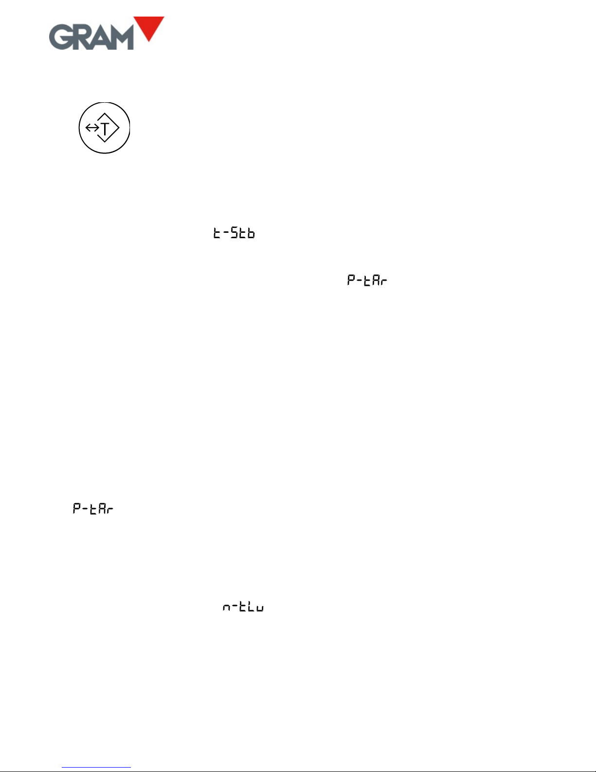
5.2. TARE AND TARE RECORD IN MEMORY ....................................... 12
5.3. ZEROING ...................................................................................... 14
5.4. LCD DISPLAY TEST ........................................................................ 14
5.5. HIGH-RESOLUTION MODE........................................................... 15
5.6. HOLD MODE ................................................................................ 15
5.7. H-L MODE (CONTROL OF UPPER/LOWER LIMITS) ...................... 16
5.8. DOSAGE MODE............................................................................ 17
5.9. PIECE COUNTER MODE ............................................................... 18
5.10. PLU - SELECTION OF PRODUCT CODE ......................................... 20
5.11. PRINTING A WEIGHING TICKET ................................................... 21
6. CONFIGURATION OPTIONS MENU .......................................................... 23
7. AUTO-OFF OPTION ................................................................................. 26
8. BACKLIGHTING THE DISPLAY ................................................................... 26
9. SOUND WHEN PRESSING A KEY ............................................................. 27
10. TARE OPTIONS ........................................................................................ 27
11. Hold MODE ............................................................................................. 27
12. KEYPAD LOCK .......................................................................................... 29
13. COMMUNICATION .................................................................................. 29
13.1. Remote indicator mode .............................................................. 32
13.2. XTREM mode ............................................................................... 32
13.3. PR4/PR6/Q2 printer .................................................................... 33
13.4. Frame format RD3 ....................................................................... 33
13.5. Frame format USB ....................................................................... 34
13.6. Frame format PC0 ....................................................................... 34
13.7. Communication protocol ............................................................ 37
14. TICKET PRINT OPTIONS .......................................................................... 38
15. CONFIGURING THE SCALE ....................................................................... 39
15.1. Settings menu ............................................................................. 40
15.2. Scale calibration .......................................................................... 40
16.3 Table of geographical adjustment values ................................... 42
16. DIGITAL FILTER ........................................................................................ 43
Page 4

4
17. WEIGHING OF LIVE ANIMALS .................................................................. 43
18. MOVEMENT FILTER ................................................................................. 43
19. INFORMATION TO BE VIEWED ................................................................ 44
20. DIGITAL OUTPUTS ................................................................................... 44
21. TECHNICAL SPECS .................................................................................... 46
22. CONNECTIONS ......................................................................................... 48
23. ERROR MESSAGES ................................................................................... 50
24. NOTES ...................................................................................................... 51
Page 5
5
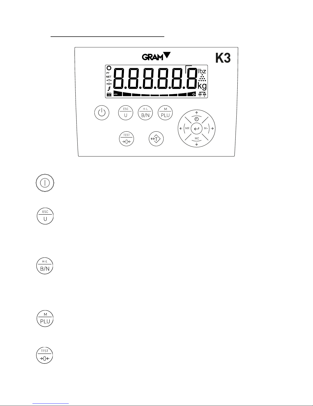
1. KEYPAD AND LCD DISPLAY
Switches the unit On / Off. Pressing it lights up the indicator. With
the indicator on, keeping it pressed for two seconds switches it off.
Piece counter mode. Activates or deactivates the piece counter
mode. Double-pressing it gives access to the options menu of the
piece counter mode. In menu mode you have the function of exiting
the menu and returning to normal mode (Escape).
Gross/Net. When the tare is used, when pressed it shows the gross
weight (total weight on the scale) and when pressed again it shows
the net weight. Keeping it pressed for more than one second
automatically selects the “Weight Limit” mode. Double-pressing it
gives access to the limits configuration menu.
PLU - product code. Pressing it gives access to the product code
memory (PLU). Keeping it pressed for more than one second leads to
the scale configuration and settings menu. Double-pressing it
activates or deactivates the HOLD mode.
Zero / Test / High-resolution. Zeroing the scale. Pressing it for more
than one second shows the display test, capacity, division and
Page 6

6
software version. Double-pressing the key activates the highresolution mode. When editing the value of an alphanumerical data,
it switches between upper case, lower case and numbers / symbols.
Tare. Pressing it once subtracts the weight of any receptacle or box
placed on the platform until the weight is removed from the platform
and this key is pressed again. Keeping it pressed switches between
“fixed tare” and “normal tare” mode. Double-pressing it gives access
to the tare memory, for selecting a record or editing the associated
tare value.
M+ and right arrow. When pressed, it adds the weight indicated in
the display to the total, initiates the accumulated ticket if it was not
yet initiated and sends the ticket data to the printer. In addition, for a
few moments it shows the accumulated total. In menu mode it
displays the next option.
MR and left arrow. When pressing on it on the main screen, it closes
and sends the totalizer ticket data and shows the accumulated weight
total. In menu mode it returns to the previous menu.
Enter. When pressing on it on the main screen, it sends the current
weight data to the printer (single ticket). Keeping it pressed for two
seconds activates the blocking/unblocking of the keypad. In menu
mode it confirms the selection/modification made.
Clock and Up Arrow. A short press displays the accumulated value in
the total. Pressing it for more than a second displays the date and
time. In menu mode, when editing the content of a parameter, it
increases the value (digit) of the display.
MC and Down Arrow. In menu mode, when editing a parameter, the
value (digit) shown in the display decreases. If kept pressed for more
than one second, it runs the “Clear” function: It voids the tare,
cancels the “hold” mode and resets the accumulated weight total.
Page 7

7
Displays the weight on the scale platform.
In HOLD mode, the reading is shown intermittently to signal that it is not indicating the real weight on the scale but the la test
stable weight recorded.
Unit of measurement in which the weight is indicated.
Piece counter mode: The display shows the number of units, not the weight.
Stable weight reading: There is a weight on the platform that is not fluctuating. Intermittent or switched off to indicate
that there is movement in the scale.
Negative sign.
This reading may be negative if a tare is activated (in preset tare mode) or to indicate a problem when setting it to zero.
Indicates net weight. The net weight is the real weight on the scale minus the tare. It is only displayed if a tare has been used.
Tare activated.
The reading flashes when “normal” tare mode has been activated.
A “preset” tare is retained even after the weight is removed from the scale platform.
Tare in memory. The tare being subtracted from the weight is a value recorded in the indicator memory, not necessarily a
measured value.
Scale set to zero: The weight on the load receptor is lower than ¼ interval (division).
Reading in high-resolution mode. It shows a division 10 times smaller than the one defined in the weighing scale range.
In double range mode, it indicates that the scale’s range 1 is being used.
In double range mode, it indicates that the scale’s range 2 is being used.
The weight is below the lower limit.
The 4 segments of this indicator are activated proportionally to the difference between the weight on the scale and the value of
the lower limit. The thickest segment indicates that the weight is lower than the value set as the lower limit in a proportion of 100%
or more.
The weight is within the interval encompassed between the lower limit and the upper limit.
The weight is above the upper limit.
The 4 segments of this indicator are activated proportionally to the difference between the weight on the scale and the value of
the upper limit. The thickest segment indicates that the weight is higher than the value set as the upper limit in a proportion of
100% or more.
Battery-operated. Not connected to the mains. The load level is indicated.
AC/DC supply connected to the power outlet.
Page 8

8
2. BEFORE USING THE SCALE
1. AC/DC adapter, output 12 Vdc – 1 A
2. Space allocated for optional enlargements
3. Connector for the C1 load receptor platform
4. RS-232 data output
5. Connector for the XTREM platform
Connect the AC/DC power source to the unit and to a power outlet suitable
for charging the battery before its first use.
Connect the load receptor platform cable in the C1 connector of the K3
indicator.
Page 9
9
The load receptor platform should be placed on a flat surface free of any
irregularities.
For the proper functioning of the instrument, the platform should be
horizontally levelled. Before using the scale, check the bubble level included
in the actual platform and adjust the levelling feet if necessary.
Both the K3 indicator and the weight sensors included in the platform are
sensitive to changes in ambient temperature. To achieve maximum precision,
we recommend you keep the scale switched on for at least 30 minutes in its
set-up site before using it.
Page 10
10
3. ON / OFF
Press on the key. The display switches on and performs the
following sequence:
1. All segments and symbols switch on for a second on the LCD display
to verify that they are functioning properly.
2. It then shows the unit’s firmware version code during one second.
3. Finally, for one second it displays the scale’s maximum capacity and
the interval.
After the power-up sequence the scale is ready for use.
To switch off the unit, press on the same power-on key and keep it pressed
for 2 seconds. An message will appear to warn that the device will be
switched off when the key is released.
4. INITIAL RESET TO ZERO
When switching on the unit, it will automatically set to zero. This will be
indicated in the display with the message .
Automatically resetting to zero at the start requires the scale to remain
stable for at least 5 seconds. For as long as the scale is moving, the
indication will be maintained for a maximum of 10 seconds.
If this time period is exceeded without obtaining a stable reading, the display
will show an message followed by the weight on the scale.
If the weight on the load receptor is higher than 10% of the scale’s maximum
capacity, the error message will be displayed, followed by the weight
on the scale.
The option in the configuration menu activates or deactivates the
initial zeroing.
Page 11
11
5. OPERATION
5.1. USE OF THE SCALE
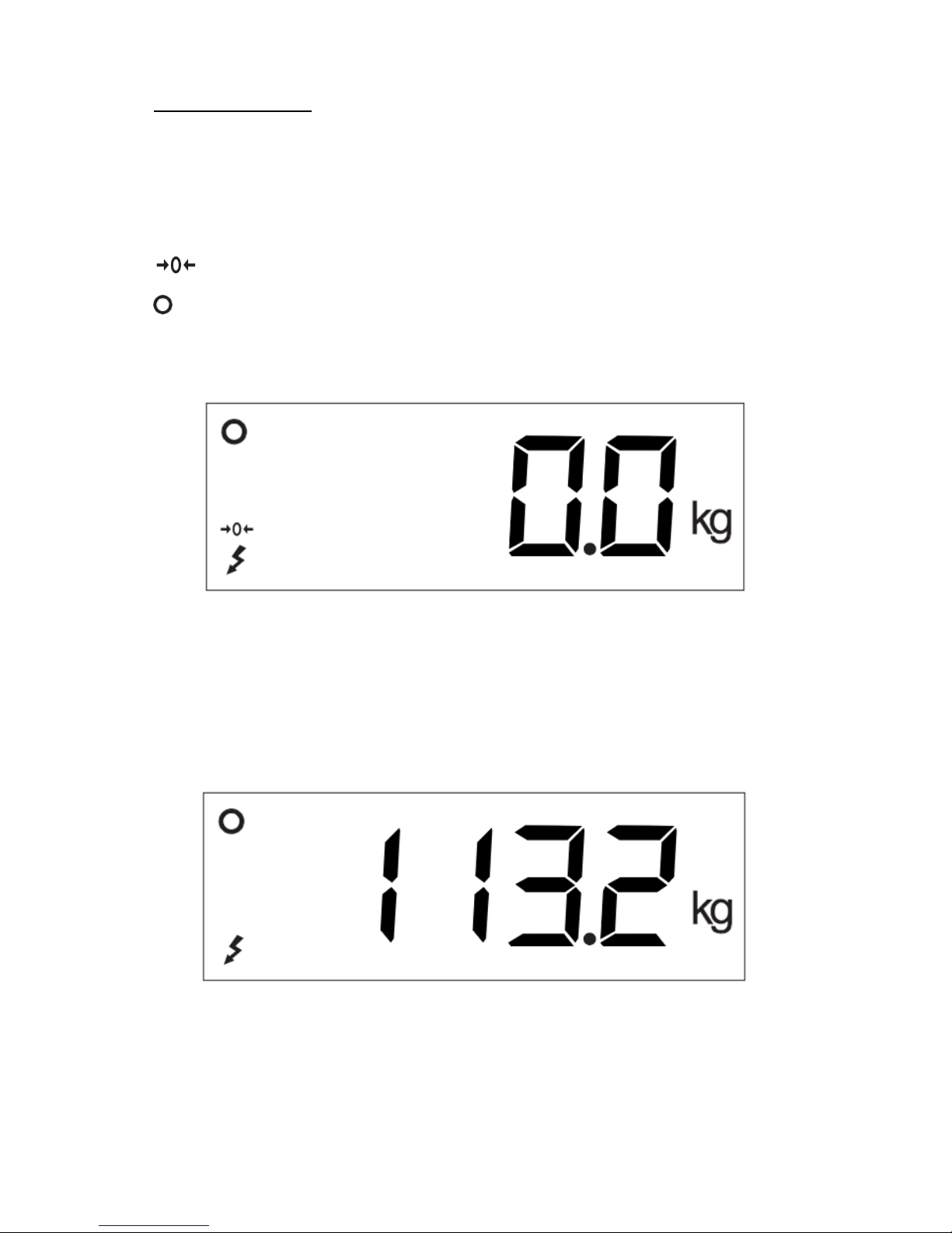
Once the unit is switched on, the weight display will indicate that the scale:
• is set to zero, meaning that there is no load placed on the platform.
• the reading is stable, that is to say, there is no external influencing
factor (such as an air current or the vibration of a nearby engine) that
may be producing significant disruption.
To find out the weight of any object within the scale’s maximum range, place
it on the load receptor platform: The zero reading and the stability reading
disappears from the indicator; the weight value will increase until the
stability reading becomes visible again. The value indicated in the display is
the result of the measurement.
Page 12
12
5.2. TARE AND TARE RECORD IN MEMORY
A short press on this key activates the tare function: The scale
memorizes the weight currently on the load receptor and
subtracts it from the total weight until the tare function is
deactivated or cancelled.
The tare function only operates if the weight is stable. If the stability indicator
is switched off, pressing this key has no effect. It is possible to change this
feature by changing the option in the configuration menu to “NO”.
It can be “Normal Tare” or “Fixed Tare” depending on the operating mode
selected in the configuration menu (see option ).
• Preset tare. The tare remains after emptying the load receptor. The >T<
indication on the display stays constant, non-flashing. When the scale is
emptied, the display shows the tare value with a negative sign. To cancel
the tare, press on the tare button again after emptying the plate.
• Normal tare. The tare is automatically deactivated when the plate is
emptied. The >T< indicator is switched on intermittently in the LCD
display.
Keeping this key pressed for 2 seconds switches the operating mode from
“fixed tare” to “normal tare”. The default operating mode for tare is “preset
tare”, although this value can be changed in the options menu (see option
).
It is possible to apply a tare previously memorized in the unit. The K3
indicator has up to 20 tare records, numbered from 1-20. Double-press the
tare key to access this record and select one of the memorized tares.
The display will show the message; press on the key, enter the tare
record number you wish to select and validate by double-pressing the key.
The display will show for one second the tare value associated to the selected
record. It will then return to the weight reading mode and will apply the tare.
Page 13
13
Should no tare value have been entered previously for the selected record,
the display shows the option of the configuration menu, which allows
the tare value to be entered.
When a memorized tare is used, the display shows the (“preset tare”)
reading.
To add a value to the tare memory or to modify the value associated to a tare
record, follow this procedure:
1. Double-press the tare key and select the desired record in the
option as indicated in the previous paragraph.
2. Once the record is selected, the display will again show the
message. Pressing on the → key on the display will show the
(“value”) option; pressing on the key will display the tare value
associated to the selected record. If no value has previously been
entered for the selected record, the K3 indicator will show the
current weight on the scale in the field for editing.
3. Enter the desired value by using the → arrow keys to change the
next digit and the ↑↓ keys to modify the value of each digit. Doublepress the key to validate the content of the display and store it in
the indicator memory.
To cancel the tare when the operating mode is “fixed tare”, with the load
receptor empty press the tare button again. The “clear” function (keep the
MC button pressed for more than one second) also deactivates the tare. The
scale’s zeroing key also deactivates the tare.
When the tare function is activated, a short press on the “B/N”
key switches between a view of the net weight and gross weight
every time the button is pressed. While net weight is displayed,
the “NET” indication will appear on the LCD display.
Page 14
14
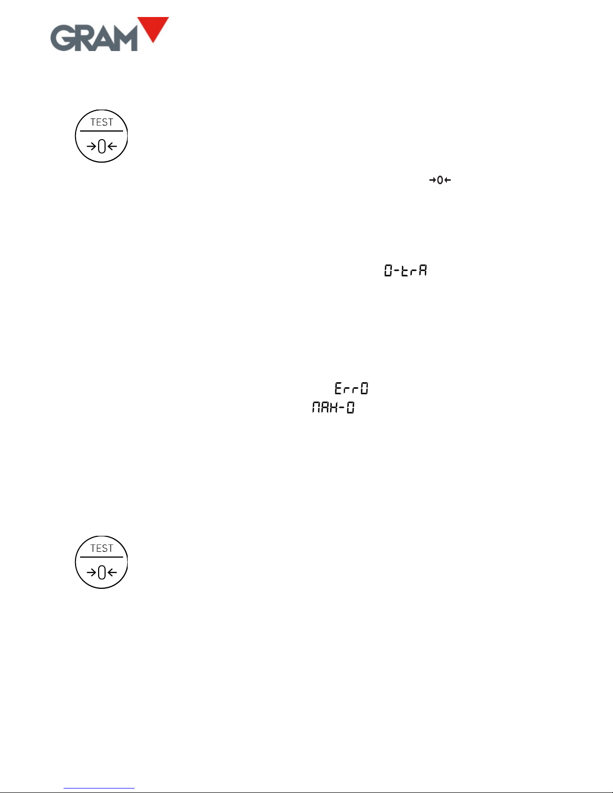
5.3. ZEROING
Zeroing the scale: A short press on this key sets it to zero. The
scale is deemed to be “set to zero” when the weight on the load
receptor is lower than ¼ of division.
While the scale is “set to zero”, the reading is shown in the display.
When the scale is set to >0< the automatic “zero tracking” device is in
operation. This function automatically sets to zero when variations of less
than ¼ division occur if they do not add up to more than ½ division during
one second. This function can be deactivated in the option of the
configuration menu.
Pressing on the >0< key also deactivates the tare if it happens to be
activated.
The zeroing of the scale is limited to 4% of its maximum capacity. Should this
margin be exceeded, the display shows the error message. It is
possible to change this margin with the option in the configuration
menu.
5.4. LCD DISPLAY TEST
Keeping this key pressed for more than one second shows the
LCD display test (all segments and pictograms switched on),
the unit’s firmware version code and, finally, the scale’s
maximum capacity and interval.
Page 15
15
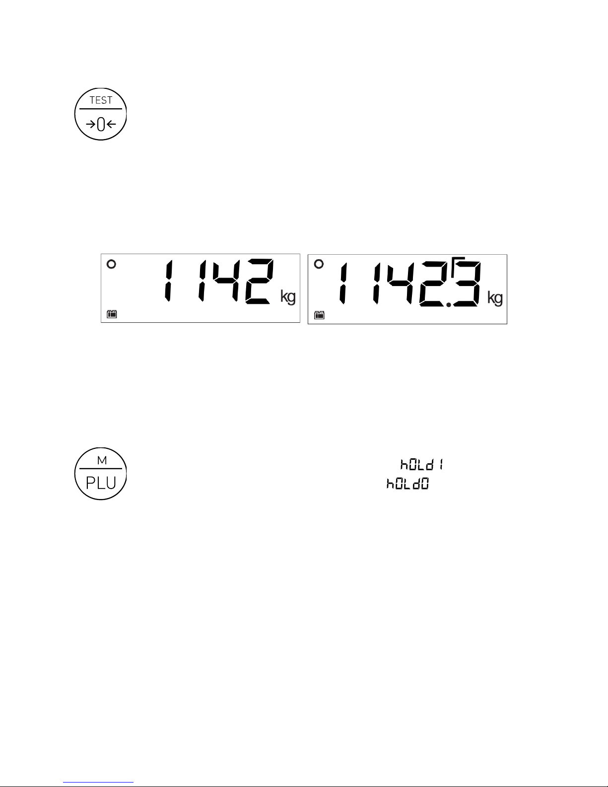
5.5. HIGH-RESOLUTION MODE
Double-pressing the TEST key activates the high-resolution mode.
In this mode the scale’s resolution is enlarged by x10, allowing the
weight to be viewed with a 10-times-smaller division.
An additional digit appears in the weight display, and the decimal point is
shifted to the left by one position. This additional digit is indicated with a
straight angle in its top left corner:
1 Example for a scale with a 1-kg division in normal mode and in high-resolution mode
5.6. HOLD MODE
Double-pressing the PLU key activates / deactivates the “HOLD”
mode. For an instant, the display shows the message to
indicate that it has been activated, or the message to
indicate that it has been deactivated.
When this operating mode is activated, the weight of the last load placed on
the plate always remains on the display. This means that, even when the load
is removed from the plate, the display continues to show the last indicated
weight. If the load has been removed, the weight is shown intermittently to
indicate that the hold mode is in operation.
Page 16
16
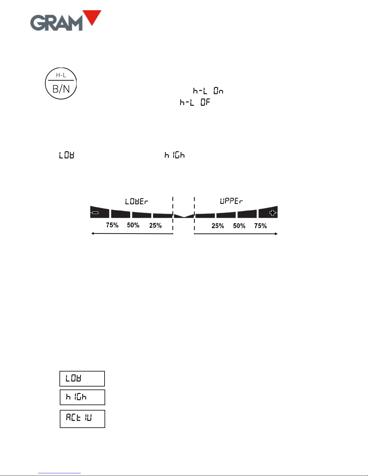
5.7. H-L MODE (CONTROL OF UPPER/LOWER LIMITS)
Keeping this key pressed for more than one second activates or
deactivates the upper and lower limit control mode. For an
instant, the display shows the message to indicate that it
has been activated, or the message to indicate that it has
been deactivated.
When the limit control is activated, a reading lights up in the bottom part of
the LCD display to signal whether the net weight on the plate is lower than
the value or higher than the value. When the weight lies between
the two values, a sign appears indicating that the weight is in the interval
defined by the lower limit and the upper limit.
The colour of the display’s backlighting changes to red when the weight is
outside the interval defined by the upper and lower limit, and changes to
green when the weight is within said interval.
The 4 segments of this reading are activated proportionally to the difference
between the net weight on the scale and the value of the lower or upper
limit. The thicker segment indicates that the weight is below the value set as
the limit in a proportion of 100% or more.
Double-press on the H-L key to access the configuration and change the
lower and upper limits. The possible options are:
Value for the lower limit, including the decimal part.
Value for the upper limit, including the decimal part.
Yes / No: Activating the limit control when switching on
the unit.
Page 17

17
5.8. DOSAGE MODE
The dosage mode is activated and configured by accessing the options menu
in the section (see section 20 in this manual).
Pressing the tare key initiates the dispense cycle, closing the K1
and K3 relay contacts. The display changes to blue to indicate that
the dispense cycle has been initiated.
Upon reaching the weight set point established for (coarse flow),
contact K1 is opened and the display colour changes to indicate that the fine
flow is in operation.
Upon reaching the weight set point established for (fine flow),
contact K3 is opened and contact K2 is closed to indicate that the dispense
cycle has finished. The light of the LCD display changes to green to indicate
that the dispense cycle has finished.
Relay K2 (signalling the end of the dispense cycle) stays closed until the
weight is removed from the scale. It is not possible to initiate a new dispense
cycle if the cycle end outlet (K2 relay contact) stays closed.
To stop and pause a dispense cycle being run, press on the “tare” key. This
action will open the K1 and K3 relay contacts, halting the filling until the tare
key is pressed again.
To cancel a dispense cycle being run, double-press on the tare key.
Page 18

18
5.9. PIECE COUNTER MODE
Pressing the “U” key activates or deactivates the piece counter
mode. In this work mode, the reading shows the number of pieces
on the scale instead of the weight.
The number of pieces is calculated by dividing the net weight on the scale by
a unit weight value.
The K3 indicator has a memory space for 20 unit weight records.
When pressing on the “U” key and changing to piece counter mode, the
message and the message appear for a moment to indicate the
unit weight record number being used (the number at the end of the
message will change from 1 to 20 depending on the selected record). When
deactivating the piece counter mode, the message appears for a
moment before returning to weight reading mode.
If the unit weight value of the selected record is outside the scale’s
measurement range, the indicator will automatically show the
option in the configuration menu of the piece counter mode. This option
allows the unit weight to be automatically calculated from a sample with a
known number of pieces.
In piece counter mode, the measurement unit is the “number of units” and is
indicated by the pictogram.
The number of pieces is always a whole number; there is no decimal fraction.
It can be a negative value if the fixed tare is kept activated and the load
receptor is completely emptied.
Page 19

19
In piece counter mode, all of the scale’s functions remain available: tare and
memorized tare, high resolution, limit control, PLU selection, ticket printing
or adhesive label.
If limit control mode is activated, the value for the lower limit and for the
upper limit refers to the number of pieces, not to the net weight on the scale.
Double-pressing on the “U” key gives access to the piece counter options
menu. The possible options are:
Selecting record number (1-20).
Automatic unit weight calculation from a sample with a
known number of pieces. For the selected record number.
Manual input of the divisor of the A/D converter count
value for calculating the number of pieces for the selected
record number.
For automatically calculating the unit weight of a piece, these are the steps to
follow:
1. Make sure that the scale is set to zero (the reading should
appear on the display). If necessary, place an empty receptacle on
the load receptor to contain the sample of pieces and perform a tare.
2. Double-press on the “U” key. The first option in the piece counter
configuration menu will appear, . Press the key.
3. Enter the piece counter record number with which you wish to work
(1 to 20) and double-press the key to validate.
4. When the message appears again, press the → key to go to
the option and press the key to access it.
5. Use the scroll keys → and . Enter in the display the number of
pieces contained in the prepared sample to calculate the unit weight
(minimum 10 pieces).
6. Double-press on the key to validate. For a few seconds the display
will show the message intermittently while it automatically
calculates the unit weight.
Page 20

20
EdIt
7. Once this process is complete, the unit weight for the selected record
is stored in the unit’s memory and the indicator will automatically
switch to piece counter mode, using the unit weight that has just
been calculated.
If the calculation of the unit weight produces a value outside the indicator’s
measurement range, the message will appear and the operation will
be cancelled.
5.10. PLU - SELECTION OF PRODUCT CODE
When pressing on the PLU key, the indicator jumps to the product
codes configuration menu to select or edit a record.
The K3 indicator has a memory with 85 PLU records.
This memory allows a 6-character alphanumerical information field to be
associated to each one of these records. This information is printed on the
weighing labels if a PLU record has previously been selected.
The possible options are:
Selection of the number of PLU records (1-85).
Inputting the 6-character alphanumerical code associated
to the selected record.
When inputting the content of the alphanumerical field, the “TEST” key
allows switching between upper case, lower case and numbers or symbols.
To cancel the selected PLU, access the option, enter the “0” value and
validate by double-pressing the key.
Page 21

21
5.11. PRINTING A WEIGHING TICKET
In “weight indicator” mode and in “piece counter” mode, the key
acts as a print key.
When pressing this key, a ticket is printed with the weight shown on the LCD
display. The ticket shows print date and time, the ticket’s serial number,
gross weight, tare and net weight. If the indicator is in piece counter mode,
the ticket shows the number of pieces, the unit weight and the tare.
The date and time are only available if the optional real-time clock accessory
is installed.
Additionally you can print a 3-line header and a footer line with constant
information.
1 Weighing ticket in weight indicator mode and in piece counter mode
Page 22

22
The print key will only be effective if the weight on the scale is stable (the
stability indicator is switched on).
This gross/tare/net ticket is only possible provided no ticket with
accumulated total has been initiated, which has a different format.
To initiate a totalizer ticket, weigh the first object to be included in
the ticket and press the M+ key. The weight shown on the display is
printed and added to the accumulated total. Repeat this operation
to add and print each one of the subsequent weighings.
At the end of each weighing sum, the total accumulated sum
appears in the display. To complete the ticket and print the line for
the total, press on the MR key. You can view the total at any time
before completing the ticket by pressing on the key.
2 Example of totalizer ticket
Page 23

23
6. CONFIGURATION OPTIONS MENU
To access the configuration options menu, keep the “M” key
pressed for two seconds. The display shows the message for
½ second to indicate that from then on the indicator will start
showing the different selection options. In “menu” mode, use the arrow keys
to change to the next option or change the value of one digit in the display
when editing the value of a parameter.
Returns to the menu’s previous level without making any
change.
When in the main menu, exit the menu mode and return to
normal operation mode (weight mode).
Moves to the next menu option in the “left” direction or
changes between the different values. It is possible to assign to
a particular option.
Moves to the next level of the options menu or shows the
current value of an option. When changing the selected value
for an option (using the and → keys), pressing this key will
validate the change. In “edition” mode (manual input of a
parameter value), one short press moves you to the next digit
on the display. A long hold or a double-press validates the
entered value.
Moves to the next menu option in the “right” direction or
changes between the different values. It is possible to assign to
a particular option.
To change the value of one digit in the display when inputting a
data item.
Page 24

24
La siguiente tabla resume las diferentes opciones de configuración y ajuste:
•
Options for automatically switching off the unit
•
Options for backlighting the LCD display
•
Activating sound when pressing on a key
•
Activating fixed tare
•
Activating automatic tare
•
Requiring stability for performing a tare
•
Operational style in “hold” mode
•
Activating keypad lock
•
Transmission speed of serial port
•
Serial port 1: Data transmission mode
•
Format of frame data sent
•
Serial port 1: “Wireless” option installed
•
… … …
Serial port 1: Wi-Fi network selection
•
Serial port 2: Data transmission mode
•
Format of frame data sent
Inputting date and time
Editing ticket number
•
Automatic paper cutting
•
Decimal separator for USB keypad adapter
•
Measurement unit of the scale
Maximum capacity (Max1 in the event of 2 ranges and intervals)
•
Division (e1 interval)
•
Position of decimal point
•
Activating double range or double interval option
Max2 in the event of 2 ranges / intervals
•
e2 in the event of double range
•
Activating initial auto-zero
•
Action range of zeroing device
Page 25

25
•
Activating zero-tracking device
•
Activating zero reading
Procedure for calibrating the scale
•
Activating automatic correction depending on geographical location
…
Selecting geographical location
Zero value in AD/C counts
Conversion factor of AD/C counts to measurement units
Printing of the configuration
Resetting the configuration to default values
AD/C pre-calibration procedure
•
Digital filtering level
•
Additional filtering for weighing moving objects or live animals
•
Activating movement filter
•
Selecting information to be viewed on the display
Piece counter: Selecting unit weight record (1-20)
Piece counter: Calculating unit weight from a sample.
Piece counter: Manually inputting the factor for calculating unit weight
•
Digital outputs: Operating mode
Digital outputs: ON/OFF test for each relay
Checkweigher mode: Lower limit
Checkweigher mode: Upper limit
•
Checkweigher mode: Activating limit control
Dosage mode: Set point for speed 1
Dosage mode: Set point for speed 2
•
Dosage mode: Selecting the “filling” or “emptying” mode of a receptacle.
•
Dosage mode: Activating dosage mode
Tares in memory: Selecting record number (1-20)
Tares in memory: Tare value for the selected record number
PLU memory: Selecting record number (1-85)
PLU memory: Alphanumerical description associated to the selected record
Batch number to be printed on the ticket
NOTE: The • symbol in the above table shows the default value for each
configuration parameter.
Page 26

26
7. AUTO-OFF OPTION
This option programs the device’s automatic switch-off after a time on idle
(not being used). The device is understood to be on idle if there is no
variation in the weight indication, and no key is pressed.
The possible options are the following:
The device always remains switched on. Option
selected at source.
The device switches off automatically after 30 minutes
of inactivity.
The device switches off automatically after 1 hour of
inactivity.
The device switches off automatically after 1:30 hours
of inactivity.
8. BACKLIGHTING THE DISPLAY
This option controls the performance of the LCD display backlight. Together
with the Auto-off option, it reduces power consumption and extends battery
life. The unit is deemed to be inactive if the scale is set to zero and there are
no changes in the weight reading and no key is pressed. The possible options
are the following:
The backlight switches off automatically after 10
seconds of inactivity. This is the option selected at
source.
The backlight is always switched off.
The backlight is always switched on.
Page 27

27
9. SOUND WHEN PRESSING A KEY
This function activates (“On”) or deactivates (“Off”) the emission of a sound
when one of the keypad buttons is pressed.
The factory setting for this option is “On”.
10. TARE OPTIONS
The possible options are:
Preset tare: The tare will be kept until the tare key is
pressed again with an empty load receptor platform.
It is the default option.
Auto-tare: When a stable weight is detected, the
indicator sets a tare automatically. When the plate is
emptied, the tare disappears (reverts to zero).
Yes (default option): The weight needs to be stable
to set a tare.
11. Hold MODE
The hold mode is activated by double-pressing the key. When this
operating mode is activated, the weight value for the last load placed on the
platform always remains in the display.
You previously need to select in the options menu the operating mode for
the hold function.
Page 28

28
To select the desired hold mode, keep the key pressed until the LCD
display shows the message giving access to the options in the configuration
menu.
Press the → key until the display shows the option and then press the
key to access this submenu.
It is possible to select three operating styles for the hold mode:
• The mode is disabled (this is the default option).
• The display shows the last stable weight placed on the scale
platform.
• The display shows the highest weight value measured by the
instrument since the last load was placed on the scale platform.
Press the → key to select the desired operating mode and then press to
validate.
The SAVE message will appear to indicate that the configuration has been
stored in the unit’s non-volatile memory. Once this option is selected, it is
recorded in the non-volatile memory and it is no longer necessary to repeat
this operation until you decide to change the mode of use.
Once the operating mode is selected for the hold key, press repeatedly on
the ESC key to return to the weight reading mode.
Double-pressing the key activates or deactivates the hold mode. When
this operating mode is activated, the last stable weight of the load deposited
on the platform will always remain in the display. In other words, even if the
load is removed from the platform, the display will continue to show the last
stable weight reading. If the load has been removed, the weight is viewed
intermittently to indicate that the hold mode is in operation.
Page 29

29
12. KEYPAD LOCK
This function locks the keypad except for the on / off button and access to
the options menu.
When a key is pressed with the keypad lock activated, no action is performed
and the display shows for 1 second. That is to say, while the keypad is
locked it is not possible to set a tare, reset to zero, print a ticket or reset total
accumulated weight.
This option stays in the memory and is not deactivated when the device is
switched off and on.
The keypad lock can be activated / deactivated by keeping the key pressed
for more than 2 seconds .
13. COMMUNICATION
The K3 indicator can be connected to other devices to send and receive
information via an RS-232 interface (standard) or a Wi-Fi 802.11 interface
(optional). The K3 indicator can have up to 2 serial RS232 outputs. The
second serial output is supplied optionally.
In the menu it is possible to configure the different data transmission
options from the indicator.
It allows the speed to be selected at which the serial
interface will be connected. The possible options are:
9600 bauds, 19200 bauds, 38400 bauds, o 57600 bauds.
The transmission format for each byte is 8 bits, without
parity bit, 1 stop bit (“8,n,1”) and it is not configurable.
Page 30

30
Configuration of serial port 1.
Configuration of serial port 2.
Each one of the serial ports is configured independently, allowing different
devices with differentiated running modes to be connected. The
configuration options available are the following:
Mode in which the data transmission will be made:
• When pressing the print key.
• Continuously, at a rate of 5 frames sent per second.
• Automatically every time there is a new stable
weight on the scale.
• Operation as remote indicator (only available for
COM1).
• Operation as a digital weight reading for a scale
equipped with XTREM. This option is only available for
the COM1 port.
• The serial port is deactivated, both for transmitting
and for receiving data.
Format of frame data to be transmitted. Enables selecting
the following options.
Connection to model PR4 printer. A ticket is sent in a format
for this printer model.
Connection to model PR6 printer. A ticket is sent in a format
for this printer model.
Page 31

31
Frame data in a compatible format with the GRAM model
Z3 weight indicator. For connecting to PC with Virtual Key
application.
Frame data in a format for the GRAM USB adapter cable.
Frame data in a format for the GRAM USBFR adapter cable
(emulating “AZERTY” keypad).
Frame data in a format for the GRAM RD3 model weight
repeater display.
Connection to Q2 labeller. A ticket is sent in a format for
this printer model.
Connection to SOLETI labeller. A ticket is sent in a format
for this printer model.
Frame data in a format for connection from another GRAM
weight indicator running as a remote display. (Only
available for COM1).
Wireless mode for use with GRAM wireless adapters. (Only
available for COM1).
“Wi-Fi 802.11” mode for use with Wi-Fi GRAM adapters.
(Only available for COM1).
Page 32

32
13.1. Remote indicator mode
The K3 indicator can operate as a remote display for another scale by using
the “GRAM remote” communication protocol. When a K3 indicator is not
configured as a remote indicator, it obtains the weight information from
another scale via the RS232 serial port. The connection available for load cell
is deactivated.
To configure a K3 indicator as a remote display, select the option in
the section of the options menu for the COM1 serial port.
The scale to which the “remote indicator” will be connected should have the
option selected in the section of the configuration options
menu for the RS232 serial port to which the cable will be connected.
Moreover, in the section of this RS232 communications port, you
should select the option (data transmission in continuous mode).
13.2. XTREM mode
When selecting the option as the operating mode for the serial port
in the options menu , the K3 indicator will operate as the
terminal of a digital scale equipped with the XTREM weight transmitter.
The weight measurement is performed by the XTREM equipment (installed in
the scale’s weight load receptor), whereas the K3 indicator is just a terminal
in which the weight reading is viewed and the instrument’s different
functions (tare, semi-automatic zero, zero-tracking device, printout of results,
piece counter, etc.) are operated.
For as long as the XTREM digital scale is not connected to the COM1 serial
port of the K3 indicator, a communication error occurs and the display shows
the “-“ sign moving along the display. For as long as this error situation is
occurring (there is no communication with the digital scale) it is not possible
to access any K3 indicator function, including the options menu.
Page 33

33
In the event of this error occurring:
• Make sure that the green LED on the XTREM scale is on (fixed or
flashing) and that the red LED that indicates a malfunction is off.
• Check that the cable of the XTREM scale is properly connected to the
COM1 serial port of the K3 indicator.
• Verify that the K3 indicator is configured at the same transmission
speed as the XTREM scale (option → ). The
transmission speed of the serial port configured as a default option in
a new unit is 9600 bauds, both for the K3 indicator and for the
XTREM weight transmitter.
If necessary, to return to the operating mode of the K3 as an analogue weight
indicator and to have access to the options and configuration menu, press
the following keys at the same time: and .
13.3. PR4/PR6/Q2 printer
When selecting this option, the scale will send weight information in a ticket
print format for GRAM PR4, PR6 printers or Q2 labeller.
The ticket can have up to 3 header lines and 1 footer line. The header and
footer content is programmable by the user.
The options for configuring this document are in the section of the
main menu.
If selecting a PR6 printer, the A-Cut (automatic paper cutting) option in the
Ticket menu automatically changes to ON.
13.4. Frame format RD3
Format compatible with GRAM RD3 weight repeater display.
When selecting this transmission format, the weight indicated by the S2 scale
appears simultaneously in the RD3 repeater.
Page 34

34
13.5. Frame format USB
Format compatible with the GRAM USB adapter for PC-type computer with
Microsoft Windows operative system.
From the PC’s point of view, the GRAM USB adapter is a keypad emulation that
transforms the information transmitted by indicator K3 into a keypad input.
This option should be selected to make the data transmission from indicator K3
compatible with a keypad input in the PC. If using a French “AZERTY” keypad,
select the format.
13.6. Frame format PC0
The indicator sends the following byte frames (always 14 bytes in length).
0 1 2 3 4 5 6 7 8 9 10
11
12
13
02h
69h
20h
20h
20h
30h
2Eh
30h
30h
30h
6Bh
67h
0Dh
03h
STX
‘I’
spc
spc
spc
0 . 0 0 0 k g
CR
ETX
0 Start of text.
1 Status (tare, zero, net, stable, unstable).
2 Sign (blank space if value is positive, or ‘-‘ if negative.
3..9 Numerical value (ASCII) of the weight shown on the LCD display, including the
decimal point.
10..11 Measurement unit: ‘g’, ‘kg’, ‘oz’, ‘lb’.
12 Carriage return.
13 End of text.
Page 35

35
The status byte is built from the binary values of the display indications (tare, zero,
gross/net and stability). 20h is added to the result to ensure that the result is
printable.
Bit 0 (01h) The transmitted value is the gross weight.
Bit 1 (02h) A tare is set.
Bit 2 Not used, always 0.
Bit 3 (08h) The indicator is set to zero.
Bit 4 Not used, always 0.
Bit 5 Not used, always 0.
Bit 6 (40h) The weight is stable.
Bit 7 Not used, always 0.
Bit 7
Bit 6
Bit 5
Bit 4
Bit 3
Bit 2
Bit 1
Bit 0
N/A
Stability
N/A
N/A
Zero
N/A
Tare
B / W
Examples:
The status byte is 61h (‘a‘)
61h – 20h = 41h ➔
Bit 7
Bit 6
(stable)
Bit 5
Bit 4
Bit 3
(no zero)
Bit 2
Bit 1
(Tare off)
Bit 0
(Gross)
0 1 0 0 0 0 0
1
The status byte is 69h (‘i‘)
69h – 20h = 49h ➔
Bit 7
Bit 6
(stable)
Bit 5
Bit 4
Bit 3
(zero)
Bit 2
Bit 1
(Tare off)
Bit 0
(Gross)
0 1 0 0 1 0 0
1
The status byte is 62h (‘b‘)
62h – 20h = 42h ➔
Bit 7
Bit 6
(stable)
Bit 5
Bit 4
Bit 3
(no zero)
Bit 2
Bit 1
(Tare on)
Bit 0
(Net)
0 1 0 0 0 0 1
0
Page 36

36
The status byte is 63h (‘c‘)
63h – 20h = 43h ➔
Bit 7
Bit 6
(stable)
Bit 5
Bit 4
Bit 3
(no zero)
Bit 2
Bit 1
(Tare on)
Bit 0
(Gross)
0 1 0 0 0 0 1
1
The status byte is 6Ah (‘j‘)
6Ah – 20h = 4Ah ➔
Bit 7
Bit 6
(stable)
Bit 5
Bit 4
Bit 3
(zero)
Bit 2
Bit 1
(Tare on)
Bit 0
(Net)
0 1 0 0 1 0 1
0
The status byte is 6Bh (‘k‘)
6Ah – 20h = 4Ah ➔
Bit 7
Bit 6
(stable)
Bit 5
Bit 4
Bit 3
(zero)
Bit 2
Bit 1
(Tare on)
Bit 0
(Gross)
0 1 0 0 1 0 1
1
Page 37

37
13.7. Communication protocol
The K3 indicator is equipped with a communication protocol that allows the unit to
be commanded remotely.
The table below lists the available commands and the response of the K3 indicator.
COMMAND
RESPONSE
v
Returns a message with the identification of the “GRAM K3
Vxxxx” firmware version.
$
Weight request. The indicator transmits a frame of weight
information in a PC0 format.
z
The scale performs auto-zeroing.
t
The scale performs a tare.
f
Increases the value of the digital filter (1..4). If the filter is 4,
the ‘f’ command sets the filter to 1.
H1
Programs line 1 of the ticket header and responds “H1 OK”.
H2
Programs line 2 of the ticket header and responds “H2 OK”.
H3
Programs line 3 of the ticket header and responds “H3 OK”.
F1
Programs the ticket’s footer line and responds “F1 OK”.
For commands H1, H2, H3 and F1, the format is the following:
0 1 2 3 4 5 6 … 30
31
32
33
34
35
STX
C C L L L L … L L L L L ETX
Where:
STX = ASCII 2
ETX = ASCII 3
C = Command (2 characters)
L = 32-character ASCII text line
Page 38

38
14. TICKET PRINT OPTIONS
This menu has various options for configuring the information that appears
printed in the tickets generated by the K3 indicator.
Setting the time on the scale’s internal clock. Only if the
optional real-time clock board is installed.
Value of the next ticket number to be printed. It is
automatically increased with each print, whether it is a single
ticket or a ticket with accumulated total.
Automatic paper cutting ON/OFF. This function is only
possible with ESC/Pos printers equipped with paper cutting
device.
Programming the ticket header and footer is not performed via the scale’s
keypad but via the RS-232 serial port. In the downloads zone of our website a
program for PC is available with Microsoft Windows operative system for
performing this function.
Page 39

39
15. CONFIGURING THE SCALE
This menu features the options for parameterizing and setting the measurement
scale of the instrument.
Measurement unit: g, kg, oz, lb.
Maximum capacity of the scale. Enter the value, including
the decimal digits.
Division: The smallest increment that the instrument can
measure. Possible values are 1, 2, 5, 10, 20 or 50.
Position of decimal point.
Configuration menu for the instrument’s options
associated with “zero”.
Initial zero setting at start Yes / No.
Allows you to select the limit of the zero-setting device.
Possible options are MAX (zero is allowed for any weight
on the scale) or OIML (follows established rules by the
OIML R76 / EN 45501 technical regulation).
Zero tracking device activated or deactivated.
Show zero indicator in the display Yes/No.
Settings menu for the instrument.
Page 40

40
15.1. Settings menu
The settings menu can be directly accessed when switching on the unit. To do
this, switch on the unit and, while the LCD test appears with all segments on,
at the same time press on the and keys (a short press, not
sustained).
Calibration using a known weight (automatically sets the
initial zero and pending calibration).
Gravity adjustment depending on the scale’s geographical
location:
ON / OFF correction (activates/deactivates automatic
correction according to geographical location).
Geographical location code (see attached table).
Manual input (keypad) of the initial zero (in ADC accounts).
Manual input of the span slope, 5 digits.
Prints a ticket with the configuration and calibration settings
in the device’s memory.
Resets all configurations to factory settings.
ADC span pre-calibration. Only to be used at factory using the
correct load cell reference.
15.2. Scale calibration
1. With the platform free of any load, select the “ ” option.
2. The display will show that the initial zero value is in progress with the
blinking message “ ”.
Page 41

41
3. Once the zero value has been calibrated, place the calibration weight (a
known mass weight) on the load receptor.
4. Enter the weight value in the indicator, including the decimal positions.
Use the cursor movement keys to move through the different positions
on the display.
5. Once you enter the weight value, double-press on the key to validate
and move to next step. The display will show the blinking message
“ “ while acquiring the calibration value.
6. Lastly, it will show the message “ ” for a few seconds, asking for the
code of the geographical location where you did the calibration. The
geographical location code is a value from 0 to 31, which you have to
choose from the attached table. Use the and → keys to change the
value and validate by pressing on the key.
7. Lastly, the message “ ” will briefly appear, indicating that the
calibration has been saved in the non-volatile memory. The indicator
returns to normal use mode, displaying the weight on the load receptor.
If the automatic correction of weight reading according to geographical
latitude and height (option “ ”) is activated, the next time the scale is
switched on after a calibration, once the display test and the initial welcome
message are completed, the user will be asked to input the value
corresponding to the geographical zone where the scale will be used.
Once the value has been entered for the geographical zone in which the scale
is used, it is recorded in the non-volatile memory and will not be requested
again.
The geographical area where the scale is used can be modified later
whenever you wish by entering the menu with → → →
→ → (for nn {0-31}).
The automatic correction of the setting according to geographical area can be
disabled by entering the menu with → → → →
→ .
Page 42

42
16.3 Table of geographical adjustment values
Geographical latitude in
the northern or southern
hemisphere in degrees
and minutes.
Elevation above sea level in metres
0
325
650
975
1300
1625
1950
2275
2600
2925
3250
325
650
975
1300
1625
1950
2275
2600
2925
3250
3575
Elevation above sea level in feet
0
1060
2130
3200
4260
5330
6400
7460
8530
9600
10660
1060
2130
3200
4260
5330
6400
7460
8530
9600
10660
11730
00°00' - 05°46'
5 4 4 3 3 2 2 1 1 0 0
05°46' - 09°52'
5 5 4 4 3 3 2 2 1 1 0
09°52' - 12°44'
6 5 5 4 4 3 3 2 2 1 1
12°44' - 15°06'
6 6 5 5 4 4 3 3 2 2 1
15° 06' - 17°10'
7 6 6 5 5 4 4 3 3 2 2
17°10' - 19°02'
7 7 6 6 5 5 4 4 3 3 2
19°02' - 20°45'
8 7 7 6 6 5 5 4 4 3 3
20°45' - 22°22'
8 8 7 7 6 6 5 5 4 4 3
22°22' - 23°54'
9 8 8 7 7 6 6 5 5 4 4
23°54' - 25°21'
9 9 8 8 7 7 6 6 5 5 4
25°21' - 26°45'
10 9 9 8 8 7 7 6 6 5 5
26°45' - 28°06'
10
10 9 9 8 8 7 7 6 6 5 28°06' - 29°25'
11
10
10 9 9 8 8 7 7 6 6
29°25' - 30°41'
11
11
10
10 9 9 8 8 7 7 6 30°41' - 31°56'
12
11
11
10
10 9 9 8 8 7 7
31°56' - 33°09'
12
12
11
11
10
10 9 9 8 8 7 33°09' - 34°21'
13
12
12
11
11
10
10 9 9 8 8
34°21' - 35°31'
13
13
12
12
11
11
10
10 9 9 8 35°31' - 36°41'
14
13
13
12
12
11
11
10
10 9 9
36°41' - 37°50'
14
14
13
13
12
12
11
11
10
10 9 37°50' - 38°58'
15
14
14
13
13
12
12
11
11
10
10
38°58' - 40°05'
15
15
14
14
13
13
12
12
11
11
10
40°05' - 41°12'
16
15
15
14
14
13
13
12
12
11
11
41°12' - 42°19'
16
16
15
15
14
14
13
13
12
12
11
42°19' - 43°26'
17
16
16
15
15
14
14
13
13
12
12
43°26' - 44°32'
17
17
16
16
15
15
14
14
13
13
12
44°32' - 45°38'
18
17
17
16
16
15
15
14
14
13
13
45°38' - 46°45'
18
18
17
17
16
16
15
15
14
14
13
46°45' - 47°51'
19
18
18
17
17
16
16
15
15
14
14
47°51' - 48°58'
19
19
18
18
17
17
16
16
15
15
14
48°58' - 50°06'
20
19
19
18
18
17
17
16
16
15
15
50°06' - 51° 13'
20
20
19
19
18
18
17
17
16
16
15
51°13' - 52°22'
21
20
20
19
19
18
18
17
17
16
16
52°22' - 53°31'
21
21
20
20
19
19
18
18
17
17
16
53°31' - 54°41'
22
21
21
20
20
19
19
18
18
17
17
54°41' - 55°52'
22
22
21
21
20
20
19
19
18
18
17
55°52' - 57°04'
23
22
22
21
21
20
20
19
19
18
18
57°04' - 58°17'
23
23
22
22
21
21
20
20
19
19
18
58°17' - 59°32'
24
23
23
22
22
21
21
20
20
19
19
59°32' - 60°49'
24
24
23
23
22
22
21
21
20
20
19
60°49' - 62°09'
25
24
24
23
23
22
22
21
21
20
20
62°09' - 63°30'
25
25
24
24
23
23
22
22
21
21
20
63°30' - 64°55'
26
25
25
24
24
23
23
22
22
21
21
64°55' - 66°24'
26
26
25
25
24
24
23
23
22
22
21
66°24' - 67°57'
27
26
26
25
25
24
24
23
23
22
22
67°57' - 69°35'
27
27
26
26
25
25
24
24
23
23
22
69°35' - 71°21'
28
27
27
26
26
25
25
24
24
23
23
71°21' - 73°16'
28
28
27
27
26
26
25
25
24
24
23
73°16' - 75°24'
29
28
28
27
27
26
26
25
25
24
24
75°24' - 77°52'
29
29
28
28
27
27
26
26
25
25
24
77°52' - 80°56'
30
29
29
28
28
27
27
26
26
25
25
80°56' - 85°45'
30
30
29
29
28
28
27
27
26
26
25
85°45' - 90°00'
31
30
30
29
29
28
28
27
27
26
26
Page 43

43
16. DIGITAL FILTER
Every 100ms, the A/D converter of the S2 scale provides a reading of the
electrical output voltage of the connected load cell.
The digital filter consists of a moving average of these readings.
Possible values are 1 (moving average of 2 readings), 2 (4 readings),
3 (8 readings), or 4 (16 readings).
A smaller filter value implies that rapid oscillations in the weight become
more visible and vice versa.
17. WEIGHING OF LIVE ANIMALS
An additional filtering is available for weighing live animals or persons which,
when moving on the load receptor, cause disruption in the weight reading by
exerting a variable force on the load cells.
By activating this filtering in conjunction with the digital filter, an average
reading is obtained that discards the extreme values caused by the shifting
on the load receptor platform.
18. MOVEMENT FILTER
When activating the movement filter, the indicator does not show
inconsistent changes of more than one division with a duration of less than
100ms.
The result is that the indicator retains the last stable value while the weight
has no consistent movement (in the same direction).
Put another way, a sudden quick blow on the scale does not have any effect
on the reading. Although the weight value shown on the display is not
affected, the stability reading in the top left corner of the display will go off
to indicate this situation.
Page 44

44
19. INFORMATION TO BE VIEWED
Allows you to select the value that should be shown in the LCD display. The
options are the following:
The indicator shows the weight. It is the default option.
Filtered A/D converter counts.
Unfiltered A/D converter counts.
20. DIGITAL OUTPUTS
This section of the options menu allows the operation of the optional 3-relay
board available for the K3 indicator to be configured.
These 3 relay outputs can be used either for controlling an external signalling
of the high/low/ok limits in the running mode as a checkweigher (H-L mode)
or for the dosage of a product at two speeds. Moreover, it is possible to
select whether the dosage is performed for filling a receptacle on the scale
(loading) or for emptying a receptacle (unloading). The options in this section
of the menu are the following:
Running mode for controlling the optional relay board.
The relay outputs will be controlled by the H-L running
mode. The K1 relay closes when the weight on the
scale is greater than the limit . The K2 relay closes
when the weight is between the and limits.
The K3 relay closes when the weight is below the
value.
The relay outputs will be controlled by the dosage
mode.
Page 45

45
Allows each one of the 3 relays to be checked and
operated by the user.
Setting the upper and lower values for running the
“checkweigher” mode.
Value of the lower limit, including the decimal part.
Value for the upper limit, including the decimal
part.
Yes / No: Activating the limits control when
switching on the unit. The H-L key activates or
deactivates the limits control.
Setting of values for dosage.
Weight set point for speed 1.
Weight set point for speed 2.
Type of dosage. Loading (LOAd) or unloading
(unLOAd).
Yes / No: Activating the dosage mode when
switching on the unit.
Page 46

46
21. TECHNICAL SPECS
Load cell connection
Maximum input signal
±4 mV/V
Maximum input voltage
-0.3 to 5.3 V
Internal resolution
AD 20bits converter, 1000000 counts (100000
external)
Measurement frequency
10 samples per second
Linearity error
≤0.01% of the measurement range
Exciting voltage
5 Vdc
Minimum transducer
impedance
· Without relay board: 31,666 Ω
(12 cells x 380 Ω)
· With relay board: 47.5 Ω (8 cells x 380 Ω)
Cable length
30 m/mm2 max. (6 wires)
User interface
Main indicator
6-digit LCD 25.4 mm in height and weight
limits visualizer.
Backlit with 3-LED (RGB) back light panel
Keypad
11-key keypad
Acoustic warning
Piezoelectric intermittent-sound mini-buzzer
(2300±300 Hz y 85 dB)
Communications
Port Tx/Rx: (Port 1)
Two-way RS-232C
Port Tx/Rx: (Port 2)
Transmission-only RS-232C.
Transmission speed
1200, 2400, 4800, 9600, 19200, 38400, 57600,
115200
Number of bits and parity
8 bits, no parity, 1 bit stop
Input / output options
Wi-Fi 802.11 board
Wi-Fi adapter for Ethernet communication via
TCP socket
RTC board
RTC for date and time
3-relay board
240VAC / Max current 15A / 360W
Page 47

47
Power
Network connection
Via 12-V supply; 1 A
Battery
6V-5AH;
Service time 25/60 hours depending on use.
Operating conditions and mechanical data
Operational
temperature range
+5ºC/+35ºC
Size (mm)
220 x 180 x 83
Weight (kg)
1.5 (including battery)
Assembly
Desktop
Optional: Swivel mount wall/column
Tightness
IP-65 (K3); IP-67 (K3i)
Thermal printer (K3iP and MK3P models)
Printer life
6000000 printed lines
Resolution
8 dots/mm
Print speed
30 mm/sec
Paper type
Thermal paper reel (57mm wide, 30 mm ø)
Print width
48 mm
Print sizes
6x8 points, 8x16 points, 12x24 points
Page 48

48
22. CONNECTIONS
C1 connector, load cell
PIN No.
SIGNAL
TYPE A
TYPE B
PIN 1
SIG -
Blue
White
PIN 2
SIG +
Brown
Green
PIN 3
MESH
Mesh
Mesh
PIN 4
EXC -
Black
Black
PIN 5
SENSE -
-
Blue
PIN 6
EXC +
Red
Red
PIN 7
SENSE +
-
Yellow
4 MULTI-PIN MOBILE MALE
(P700) 7 PINES
Page 49

49
5 MULTI-PIN MOBILE MALE
(P700) 8 PINES
6 MULTI-PIN MOBILE MALE (P700)
5 PINES
RS-232 serial output
XTREM scale connector
PIN No.
SIGNAL
PIN 4
RxD
PIN 5
TxD
PIN 6
GND
PIN No.
SIGNAL
PIN 1
+Vcc
PIN 2
TxD
PIN 3
RxD
PIN 4
No conectado
PIN 5
GND
Page 50

50
23. ERROR MESSAGES
ADC fault: No response from
ADC.
Malfunction in scale. Consult
helpdesk.
Sensor input signal too high
(>20mV).
Faulty load cell. Cabling in
poor condition.
Sensor input signal too low
(<-20mV).
Faulty load cell. Cabling in
poor condition.
Dead battery.
Connect the AC/DC adapter
to charge the battery.
a) Auto-zero device out of
range.
b) A stable measurement
could not be obtained when
attempting initial zeroing.
Empty the load receptor
before switching on the scale.
Calibration weight > Max.
Calibration weight should be
< Max.
The division should be >10 ADC
counts.
Resolution is too high.
Change the division to a
higher value.
A stable measurement could
not be obtained for setting the
scale.
Overload: Weight > Max+9·div
The keypad locking function is
activated.
Unlock the keypad by keeping
the key pressed for two
seconds.
The optional RTC is not present
or the circuit is damaged.
Consult helpdesk.
A totalizer ticket has now been
initiated.
Print the total before
initiating a new ticket.
Page 51

51
24. NOTES
_______________________________________________________________
_______________________________________________________________
_______________________________________________________________
_______________________________________________________________
_______________________________________________________________
_______________________________________________________________
_______________________________________________________________
_______________________________________________________________
_______________________________________________________________
_______________________________________________________________
_______________________________________________________________
_______________________________________________________________
_______________________________________________________________
_______________________________________________________________
_______________________________________________________________
_______________________________________________________________
_______________________________________________________________
_______________________________________________________________
_______________________________________________________________
_______________________________________________________________
_______________________________________________________________
_______________________________________________________________
_______________________________________________________________
_______________________________________________________________
_______________________________________________________________
_______________________________________________________________
_______________________________________________________________
_______________________________________________________________
_______________________________________________________________
_______________________________________________________________
_______________________________________________________________
Page 52

52
003/25032019
 Loading...