

Graff G-8021 T Series, G-8038 T Series, G-8044 T Series, G-8039 T Series, G-8034 T Series Installation Instructions Manual
...Page 1
THERMOSTATIC SET
CONJUNTO TERMOSTÁTICO
This faucet complies with NSF61/9, ASME/ANSI A112.18.1
and CSA B 125 Standards.
Este grifo se encuentra conforme con losestandares de NSF61/9,
de ASME/ANSI A112.18.1 y de CSA B 125.
Dear Customer Estimado Cliente
ENGLISH
Thank you for selecting our product. We are confident we can fully satisfy Muchas gracias por elegir nuestro producto. Estamos seguros que podemos
your expectations by offering you a wide range of technologically advanced satisfacer completamente sus expectativas ofreciéndole una amplia variedad
products which directly result from our many years of experience in faucet de productos tecnológicamente avanzados que resultan direct
and fitting production. muchos años de experiencia en grifos y su producción apropiada.
Installation Instructions Instrucciones de Instalación
~
ESPANOL
amente de
ATTENTION!
For care, use soft towel with soap and water only! Under no
circumstances should you use any chemicals.
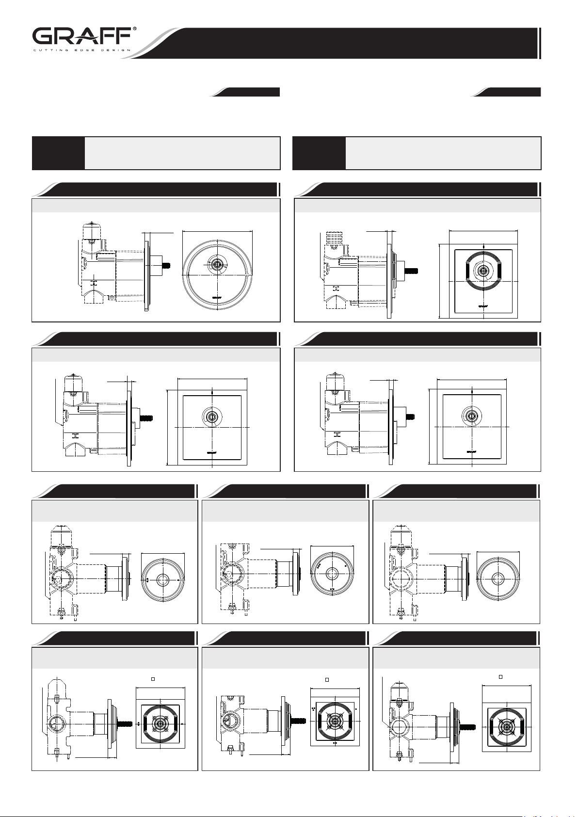
G-8031-**-T
Concealed thermostat module - exposed parts
Ø4-13/16”
(122mm)
- G-8006
Rough
3/8”
(9mm)
G-8144-**-T
Concealed thermostat module - exposed parts
4-3/4”
(120mm)
Rough - G-8006
5/16”
(8mm)
5-1/8”
(130mm)
Para el cuidado, utilice solamente una toalla suave con jabón
ATENCIÓN!
y aqua! Bajo ninguna circunstancia no use productos químicos.
G-8044-**-T
Concealed thermostat module - exposed parts
5/16”
- G-8006
Rough
5-1/8”
(130mm)
G-8021-**-T
Concealed thermostat module - exposed parts
4-3/4”
(120mm)
Rough - G-8006
5/16”
(8mm)
5-1/8”
(130mm)
4-3/4”
(120mm)(8mm)
G-8038-**-T
Concealed 2-way diverter module
Rough - G-8052
- exposed parts
3/8” (9mm)
Ø2-9/16”
(65mm)
OFF
G-8073-**-T
Concealed 2-way diverter module
Rough - G-8052
- exposed parts
5/8” (16mm)
3-1/2”
(89mm)
OFFOFF
G-8039-**-T
Concealed 3-way diverter module
Rough - G-8053
- exposed parts
3/8” (9mm)
Ø2-9/16”
(65mm)
OFF
F
F
O
O
F
F
G-8074-**-T
Concealed 3-way diverter module
Rough - G-8053
- exposed parts
5/8” (16mm)
3-1/2”
(89mm)
OFF
OFF
OFF
OFF
G-8034-**-T
Concealed cut-off valve module
Rough - G-8076
- exposed parts
3/8” (9mm)
Ø2-9/16”
(65mm)
ON
OFF
G-8099-**-T
Concealed cut-off valve module
Rough - G-8076
OFF
OFF
- exposed parts
5/8” (16mm)
3-1/2”
(89mm)
OFFONOFF
ON
IOG 2873.40
1
Rev. 9 July 2018
Page 2
This faucet complies with NSF61/9, ASME/ANSI A112.18.1
and CSA B 125 Standards.
Este grifo se encuentra conforme con losestandares de NSF61/9,
de ASME/ANSI A112.18.1 y de CSA B 125.
THERMOSTATIC SET
CONJUNTO TERMOSTÁTICO
Installation Instructions Instrucciones de Instalación
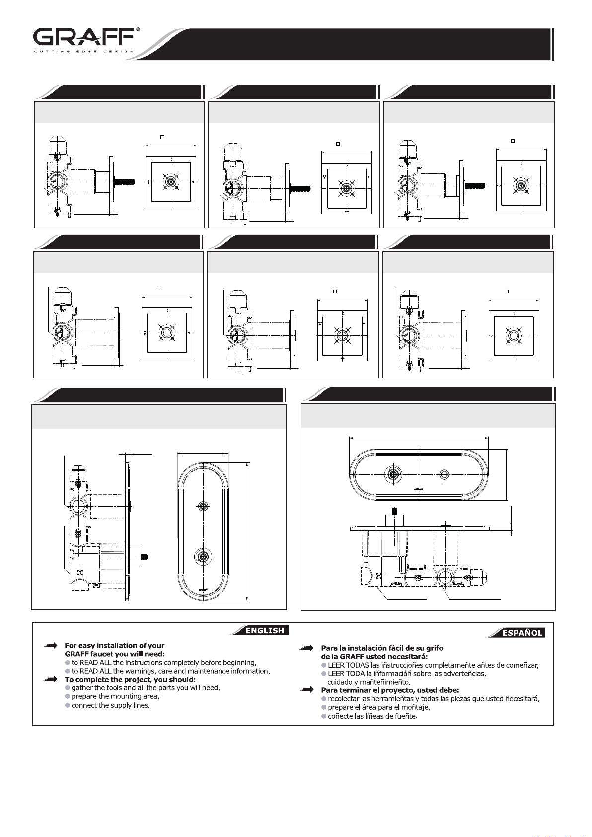
G-8173-**-T
Concealed 2-way diverter module
Rough - G-8052
- exposed parts
5/16” (8mm)
3-1/2”
(89mm)
OFFOFF
G-8028-**-T
Concealed 2-way diverter module
Rough - G-8052
- exposed parts
5/16” (8mm)
3-1/2”
(89mm)
OFFOFF
G-8174-**-T
Concealed 3-way diverter module
Rough - G-8053
- exposed parts
5/16” (8mm)
3-1/2”
(89mm)
OFFOFF
OFF
OFF
G-8029-**-T
Concealed 3-way diverter module
Rough - G-8053
- exposed parts
5/16” (8mm)
3-1/2”
(89mm)
OFFOFF
OFF
OFF
G-8199-**-T
Concealed cut-off valve module
Rough - G-8076
OFF
OFF
- exposed parts
5/16” (8mm)
3-1/2”
(89mm)
OFFOFF
ONON
G-8024-**-T
Concealed cut-off valve module
Rough - G-8076
OFF
OFF
- exposed parts
ONON
5/16” (8mm)
3-1/2”
(89mm)
OFFOFF
G-8086-**-T
Traditional two holes trim plate - exposed parts
Rough - G-8052
or G-8053 or G-8076
Rough - G-8006
3/8”
(9mm)
3-15/16” (100mm)
10-11/16” (272mm)
G-8086H-**-T
Round two holes trim plate - exposed parts
10-11/16” (272mm)
3-15/16” (100mm)
3/8”
(9mm)
Rough -G-8006
Rough -G8052
or G-8053 or G-8076
IOG 2873.40
2
Rev. 9 July 2018
Page 3
This faucet complies with NSF61/9, ASME/ANSI A112.18.1
and CSA B 125 Standards.
Este grifo se encuentra conforme con losestandares de NSF61/9,
de ASME/ANSI A112.18.1 y de CSA B 125.
THERMOSTATIC SET
CONJUNTO TERMOSTÁTICO
Installation Instructions Instrucciones de Instalación
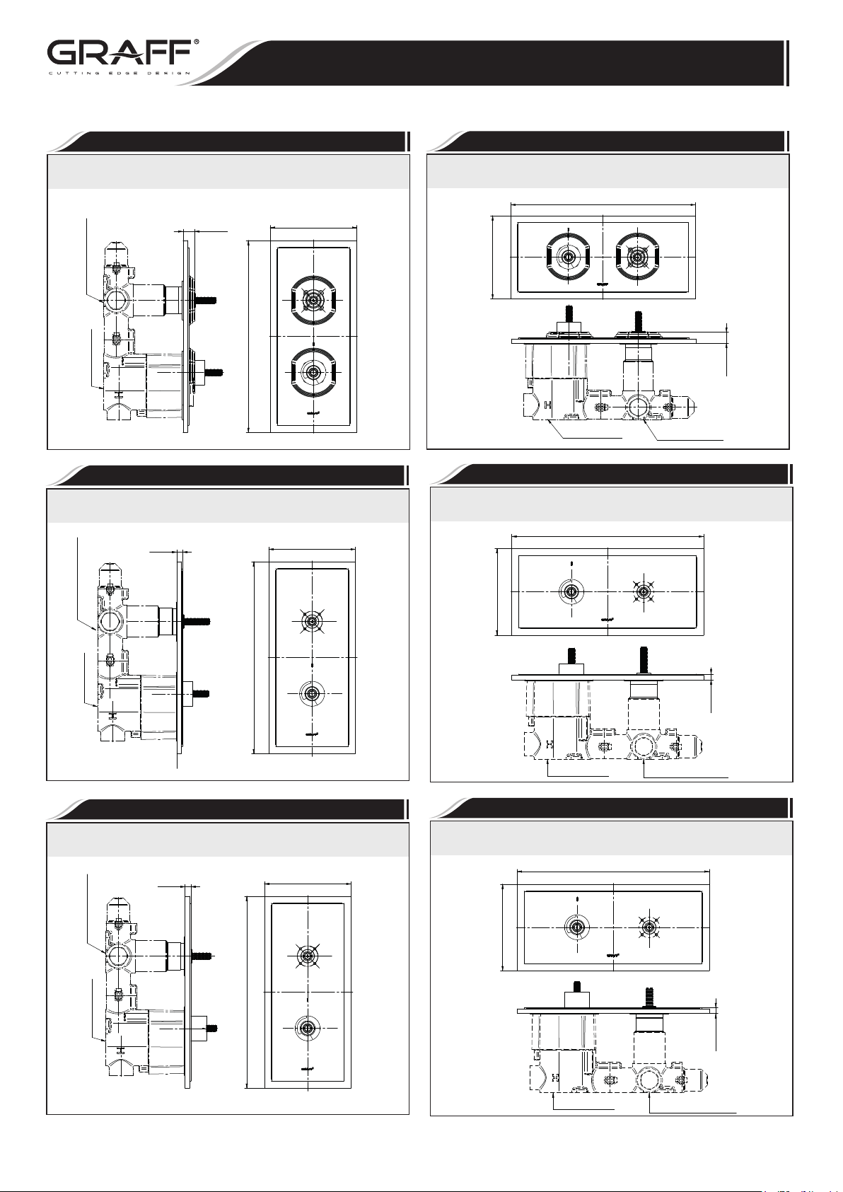
G-8049-**-T
Square two holes trim plate - exposed parts
Rough - G-8052
or G-8053 or G-8076
Rough - G-8006
5/8”
(16mm)
10-1/2” ( 266mm)
4-3/4” ( 120mm)
G-8149-**-T
Round two holes trim plate - exposed parts
5/16”
(8mm)
4-3/4” ( 120mm)
G-8049H-**-T
Square two holes trim plate - exposed parts
10-1/2” ( 266mm)
4-3/4” (120mm)
5/8”
(16mm)
Rough -G-8006
Rough -G8052
or G-8053 or G-8076
G-8149H-**-T
Round two holes trim plate - exposed parts
10-1/2” ( 266mm)
Rough - G-8052
or G-8053 or G-8076
10-1/2” ( 266mm)
Rough - G-8006
G-8081-**-T
Traditional two holes trim plate - exposed parts
Rough - G-8052
or G-8053 or G-8076
5/16”
(8mm)
4-3/4” ( 120mm)
4-3/4” (120mm)
5/16”
(8mm)
Rough -G-8006
Rough -G8052
or G-8053 or G-8076
G-8081H-**-T
Round two holes trim plate - exposed parts
10-1/2” ( 266mm)
4-3/4” (120mm)
Rough - G-8006
IOG 2873.40
10-1/2” ( 266mm)
5/16”
(8mm)
Rough -G-8006
3
Rough -G8052
or G-8053 or G-8076
Rev. 9 July 2018
Page 4
RH1
This faucet complies with NSF61/9, ASME/ANSI A112.18.1
and CSA B 125 Standards.
Este grifo se encuentra conforme con losestandares de NSF61/9,
de ASME/ANSI A112.18.1 y de CSA B 125.
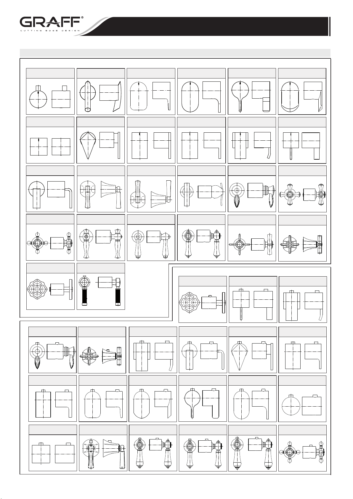
Type of Handles • Tipos de manecillas
Handles for valves.
LM24E1
LM42E1
THERMOSTATIC SET
CONJUNTO TERMOSTÁTICO
Installation Instructions Instrucciones de Instalación
LM44S1
LM46E1
LM45E1
SH1
LM40E1
C2E1
C18E1
LM23E1
LM31E1
LM47E1 LM47E2
LM22E1
LM48E1
LM56E1
LM36E1
LM20E1
LM15E1
LM38E1
LM14E1
C16E1
Handles for thermostatic valves.
C18E
LM39E
LM39E1
C3E1
C15E1
LM38E
IOG 2873.40
LM14E
C14E
SH
C15E
LM42E
LM47E
LM38E
LM45E
LM34E
LM40E
LM46E
LM15E
4
LM23E
LM44E
LC1E
LM31E
RH
C2E
Rev. 9 July 2018
Page 5
This faucet complies with NSF61/9, ASME/ANSI A112.18.1
and CSA B 125 Standards.
Este grifo se encuentra conforme con losestandares de NSF61/9,
de ASME/ANSI A112.18.1 y de CSA B 125.
THERMOSTATIC SET
CONJUNTO TERMOSTÁTICO
Installation Instructions Instrucciones de Instalación
LM22E
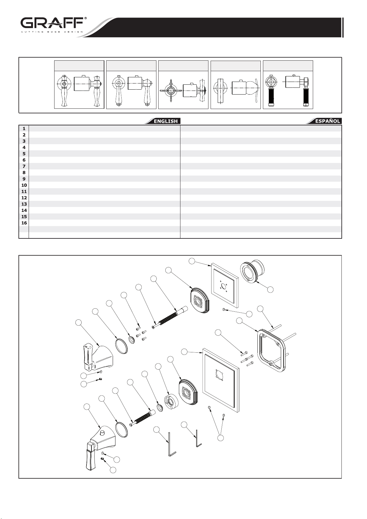
HANDLE (FOR THE THERMOSTATIC VALVE)
HANDLE (FOR THE EMBEDDED VALVE)
THERMOSTATIC VALVE ROSETTE
EMBEDDED VALVE ROSETTE
LEVER BASE (OPTIONAL)
MOUNTING PLATE
VALVE FLANGE
TEMPERATURE LIMITING RING
HEAD SPINDLE ELONGATION
SCREW
SLIDE WASHER
TEFLON SLIP RING
SCREW
SCREW M4X60
HOLE PLUG
SCREW
2MM HEX KEY
A
2,5MM HEX KEY
B
LM48E
C16E
LM20E
MANECILLA (PARA LA VÁLVULA TERMOSTÁTICA)
MANECILLA (PARA LA VÁLVULA INCORPORADA)
ROSETA DE LA VÁLVULA TERMOSTÁTICA
ROSETA DE LA VÁLVULA INCORPORADA
BASE DE LA MANECILLA (OPCIONAL)
CHAPA DE MONTAJE
BRIDA DE LA VÁLVULA
ANILLO LIMITADORE TEMPERATURA
EXTENSIÓN DEL HUSO DE LA CABEZA
TORNILLO
ARANDELA DESLIZANTE
ANILLO DE CORREDERA DE TEFLON
TORNILLO
TORNILLO M4X60
OBTURADOR
TORNILLO
LLAVE ALLEN 2MM
LLAVE ALLEN 2,5MM
LM56E
4
5
9
10
13
11
12
2
13
3
5
8
16
15
10
12
1
11
9
B
A
16
16
6
7
14
IOG 2873.40
16
15
5
Rev. 9 July 2018
Page 6
This faucet complies with NSF61/9, ASME/ANSI A112.18.1
and CSA B 125 Standards.
Este grifo se encuentra conforme con losestandares de NSF61/9,
de ASME/ANSI A112.18.1 y de CSA B 125.
THERMOSTATIC SET
CONJUNTO TERMOSTÁTICO
Installation Instructions Instrucciones de Instalación
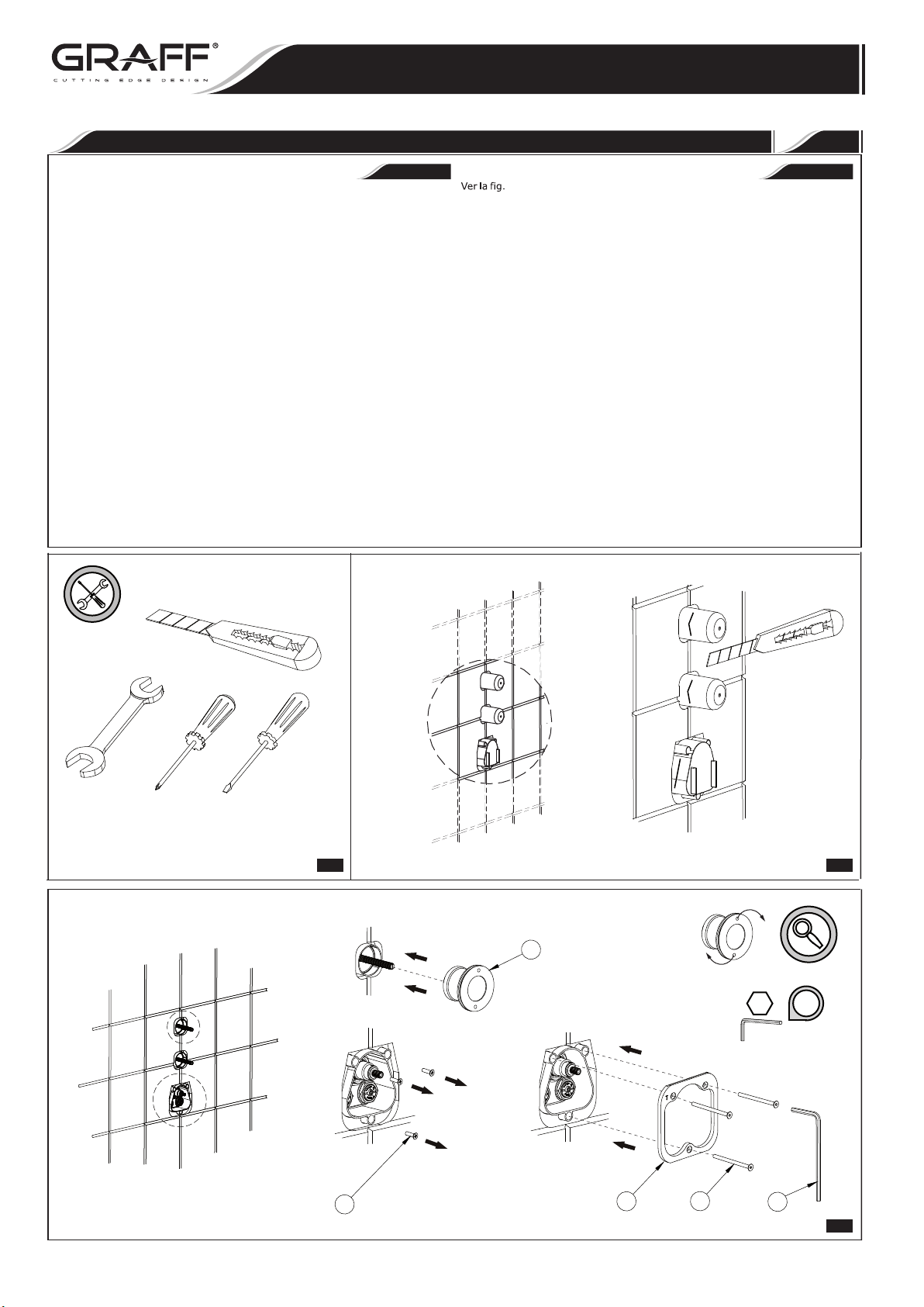
See figs. 1-8.4
ENGLISH
1.
Precisely cut off the installation covers (fig. 2).
2.
Unscrew 3 screws (T1) from the thermostatic valve cover. Keeping
them in their place, screw in the screws (14) for mounting the
thermostatic valve plate (6). Use a hex key (B) for this purpose.
Screwa mounting flange (7) into the valve bushing (fig. 3.1) until it
stops.
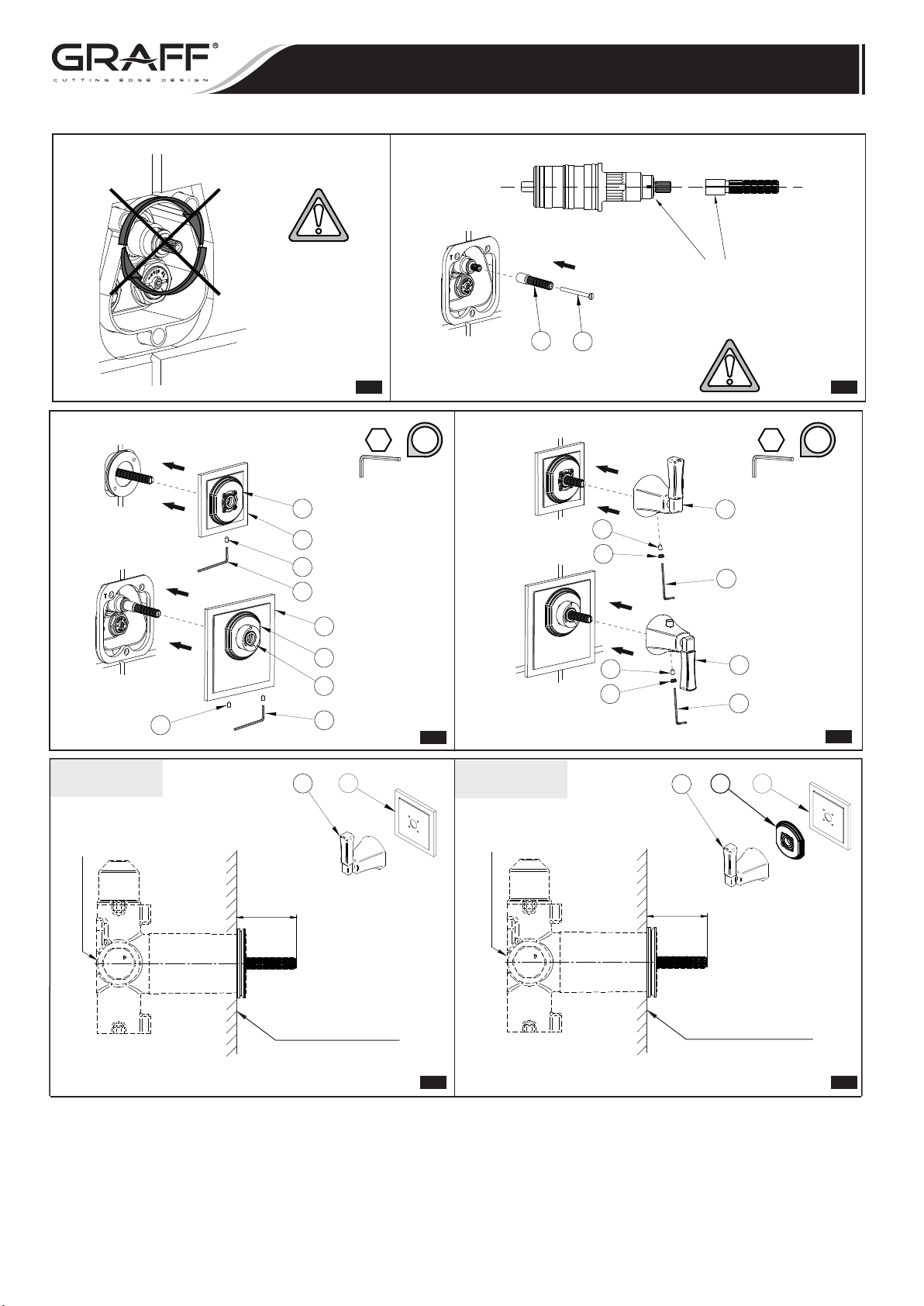
Put an extension (9) on the thermostatic valve spindle according to
3.
the markings. Attach it with a screw (10). Do not turn the valve using
the spindle! (fig. 3.2 and 3.3).
4.
Put rosettes (3), (4) onto the thermostatic valve plate (6) and the
valve mounting flange (7). Connect them with screws (16), using the
hex key (A) (fig. 4 and 5).
5.
Depending on the rosette version, the length of the valve extensions
to assemble should fit the ranges shown in fig. 6.1 or 6.2.
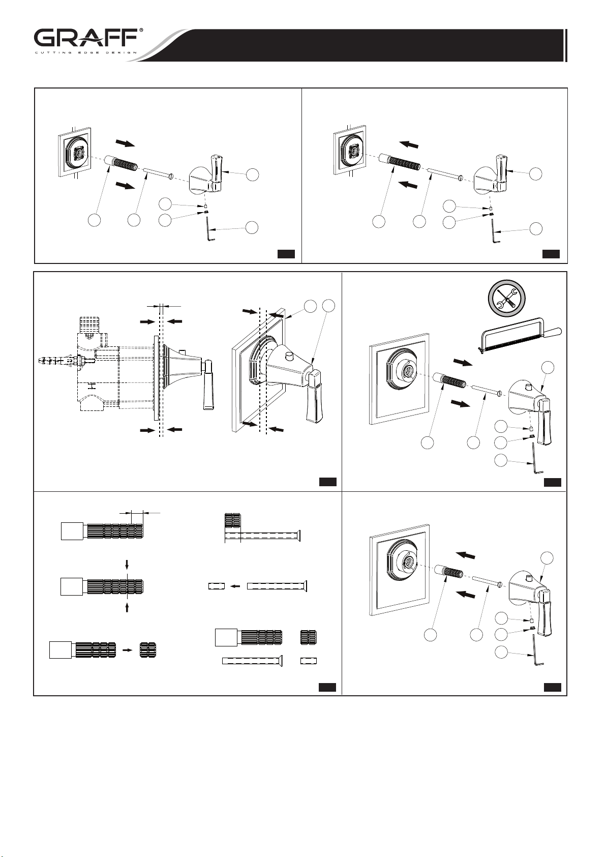
Put the handle (2) onto standard valve extensions (T2).
6.
•
If the extension is too short, it should be replaced with the longer
extension supplied with the set (9). For that purpose, remove the
handle (2), unscrew the screw (T3) and remove the extension
(T2). To assemble the longer extension (9), follow the steps in
reverse order (fig. 7.1 and 7.2).
•
If the extension is too long, cut it off with the screw (see fig.
8.1-8.4).
7.
Put the handle (1), (2) onto the extension and connect it with a
screw (16). Put the cap on (15).
INSTALLATION • INSTALACIÓN
~
1-8.4
1.
Corta con precisión las tapas de montaje (fig.2).
2.
Desenrosque los 3 tornillos (T1) de la tapa de la válvula termostática.
En su lugar, atornille los tornillos (14) para montar la placa de la
válvula termostática (6). Use una llave hexagonal (B) para realizar
esto. Atornille una brida de montaje (7) en el casquillo de la válvula
(fig. 3.1) hasta que se detenga.
Ponga una extensión (9) en el huso de la válvula termostática de
3.
acuerdo con las marcas. Fíjelo con un tornillo (10). ¡No gire la válvula
usando el huso! (fig.3.2 y 3.3).
4.
Ponga rosetas (3), (4) sobre la placa de la válvula termostática (6)
y la brida de montaje de la válvula (7), únalas con tornillos (16),
usando la llave hexagonal (A) (fig. 4 y 5).
5.
Dependiendo de la versión de la roseta, la longitud de las extensiones
de la válvula para montar debe encajar en los rangos mostrados en la
fig. 6.1 o 6.2.
6.
Ponga la manecilla (2) sobre las extensiones de la válvula estándar
(T2).
•
si la extensión es demasiado corta, debe ser reemplazada con una
extensión más larga suministrada con el conjunto (9). A tales
efectos, quite la manecilla (2), desatornille el tornillo (T3) y quite
la extensión (T2). Para montar la extensión más larga (9), siga
los pasos en sentido contrario (fig. 7.1 y 7.2).
•
si la extensión es demasiado larga, córtela con el tornillo (ver fig.
8.1 – 8.4).
7.
Ponga la manecilla (1), (2) sobre la extensión y únala con un tornillo
(16). Ponga la tapa (15).
ESPANOL
1
MAX
MAX
X
A
M
1 2
7
2,5
i
IOG 2873.40
T1
6
6
14
B
3.1
Rev. 9 July 2018
Page 7
This faucet complies with NSF61/9, ASME/ANSI A112.18.1
and CSA B 125 Standards.
Este grifo se encuentra conforme con losestandares de NSF61/9,
de ASME/ANSI A112.18.1 y de CSA B 125.
THERMOSTATIC SET
CONJUNTO TERMOSTÁTICO
Installation Instructions Instrucciones de Instalación
16
Do not turn the spindle!
¡No girar el huso!
3.2
5
4
16
A
3
5
8
A
Install according the markings
Poner conforme con la marcación
9
10
3.3
2
i
16
15
16
15
4
2
2
A
1
A
i
5
Version „A”
Rough - 5119200
or 5119300 or 5119400
2
MIN 34
MAX 49
Finished wall
Pared de acabado
4
Version „B”
Rough - 5119200
or 5119300 or 5119400
6.1 6.2
2
MIN 42
MAX 57
Finished wall
Pared de acabado
4
5
IOG 2873.40
7
Rev. 9 July 2018
Page 8
This faucet complies with NSF61/9, ASME/ANSI A112.18.1
and CSA B 125 Standards.
Este grifo se encuentra conforme con losestandares de NSF61/9,
de ASME/ANSI A112.18.1 y de CSA B 125.
THERMOSTATIC SET
CONJUNTO TERMOSTÁTICO
Installation Instructions Instrucciones de Instalación
T2
T3
15
16
H
2
16
A
7.1
1
3
9
10
15
16
9
10
15
A
2
A
7.2
1
8.1
A
H
B
C
D
E
10
16
15
A
F
9
8.3
8.2
1
8.4
IOG 2873.40
8
Rev. 9 July 2018
Page 9
This faucet complies with NSF61/9, ASME/ANSI A112.18.1
and CSA B 125 Standards.
Este grifo se encuentra conforme con losestandares de NSF61/9,
de ASME/ANSI A112.18.1 y de CSA B 125.
THERMOSTATIC SET
CONJUNTO TERMOSTÁTICO
Installation Instructions Instrucciones de Instalación
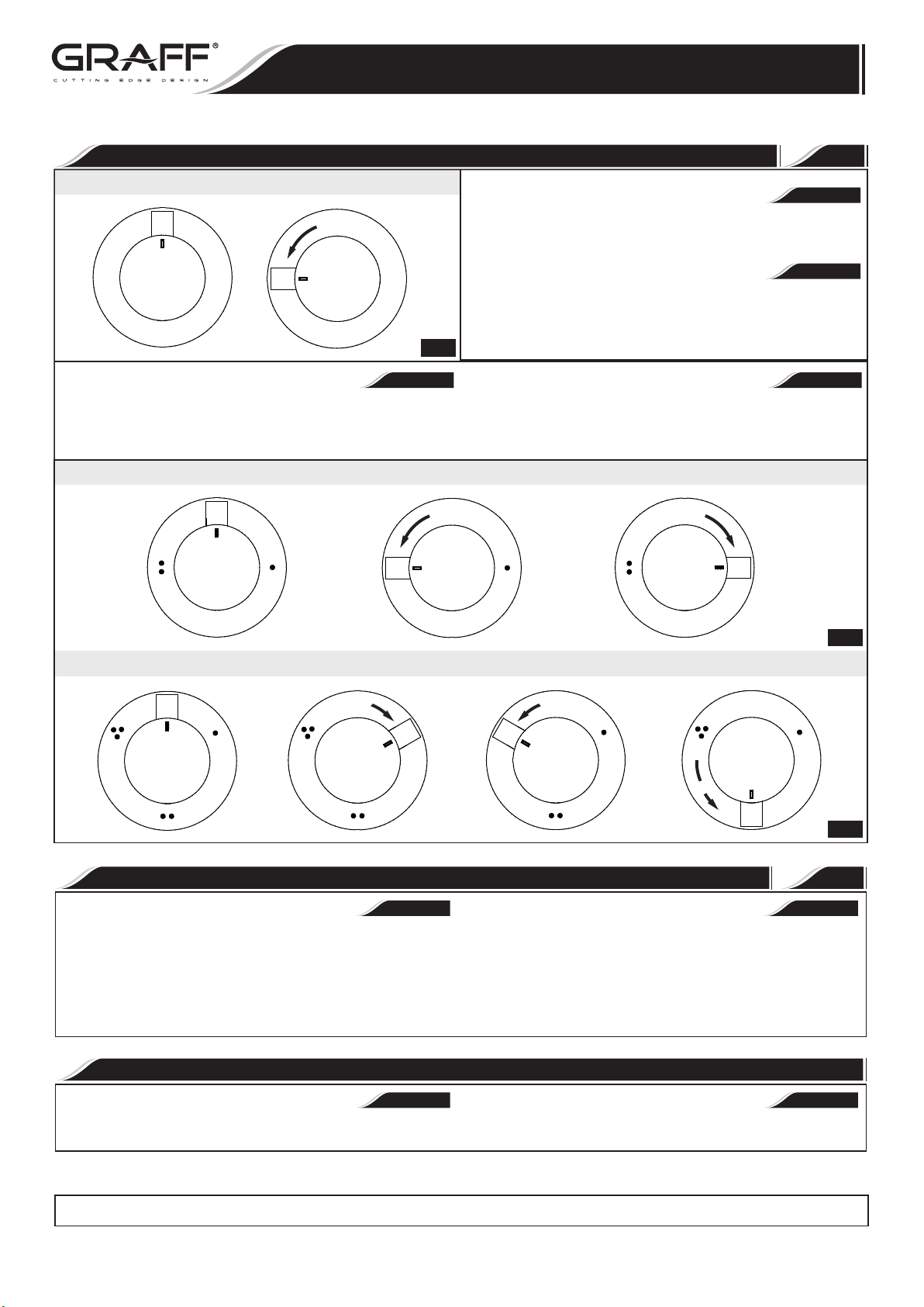
OPERATING INSTRUCTION
Concealed stop/volume control valve
OFF
ON
3.1
ENGLISH
Receiver selection is made by turning the lever (handwheel) in the desired
direction – to the markings on the escutcheon. Moving the lever
(handwheel) to the position presented in Fig. 3.2, 3.3 will cut off the water
flowvalve “closed”.
Concealed 2-way diverter
OFF
INSTRUCCIÓN DE USO
4
ENGLISH
The water flow is opened using the lever or the cross handle. It is opened
fully by turning the lever (cross handle) in counterclockwise direction.
~
ESPANOL
Para abrir la salida I de ajuste de temperatura sirve la palanca o la llave
cruzados. Obtenemos la apertura completa girando la palanca (la llave
cruzados) en la dirección opuesta al movimiento del reloj.
~
ESPANOL
La selección del tipo de receptor se debe hacer girando la palanca (el
volante) en las posiciones escogidas, marcadas en la roseta. Girar la
palanca (el volante) a la posición conforme con la fig. 3.2, 3.3 cierra la salida
del agua – la válvula en la posición “cerrada”.
OFF
Concealed 3-way diverter
OFF
OFFOFF
OFF
OFF
CARE AND MAINTENANCE CUIDADO Y MANTENIMIENTO
ENGLISH
Your Graff faucet is designed and engineered in accordance with the
highest quality and performance standards. Be sure not to damage the
finish during installation. Care should be given to the cleaning of this
product. Although its finish is extremely durable, it can be damaged by
harsh abrasives or polish. Never use abrasive cleaners, acids,
solvents, etc. to clean any Graff product. To clean, simply wipe
gently with a damp cloth and blot dry with a soft towel.
ENGLISH
Warranty conditions and warranty registration card are outlined on a
separate sheet.
3.2
OFF
OFF
OFF
OFF
OFF
OFF
3.2
5
~
ESPANOL
Su grifo de la Graff esta diseńado y dirigido acuerdo con los estándares de
funcionamiento y calidad más altos. Este seguro no dańar las terminaciones
del grifo durante la instalación. Cuide el producto manteniendolo siempre
limpio. Aunque su acabado es extremadamente durable
por los abrasivos o pulientes ásperos. Nunca utilice limpiadores
abrasivos, ácidos, solventes, el etc. para limpiar cualquier producto
de la Graff. Para limpiar, simplemente use un pańo húmedo y seque
con una toalla suave.
, puede ser
WARRANTY GARANTÍA
Las condiciones de la garantía y la tarjeta del registro de la garantía se
encuentran en una pagina separada.
dańado
~
ESPANOL
IOG 2873.40
All dimensions and drawings are for reference only. For details, please refer to actual products.
Todas las dimensiones y dibujos sirven únicamente de referencia. Para consultar detalles, ver los productos.
9
Rev. 9 July 2018
 Loading...