

Page 1

EXTENSION KIT for Wall-Mounted Thermostatic Showering Panel
JUEGO DE EXTENSIÓN para Panel de Ducha para Montar en la Pared
Installation Instructions ● Instrucciones de Instalación
Dear Customer Estimado Cliente
Thank you for selecting our product. We are confident we can fully satisfy
your expectations by offering you a wide range of technologically advanced
products which directly result from our many years of experience in faucet
and fitting production.
For care, use sof t towel with soap and water only! Under
ATTENTION! ATENCIÓN!
no circumstances should you use any chemicals. Please
be extra careful not to damage, scuff or ruin the finish
during the installation and cleaning!
Muchas gracias por elegir nuestro producto. Estamos seguros que podemos
atisfacer completamente sus expectativas ofreciéndole una amplia variedad
de productos tecnológicamente avanzados que resultan directamente de
muchos años de experiencia en grifos y su producción apropiada.
Para el cuidado, utilice solamente una toalla suave con jabón
y aqua! Bajo ninguna circunstancia no use productos quími
cos. Hay que tener un cuidado especial para no dañar, arañar o destruir el acabado durante su instalación o limpieza!
-
8322
Extension Kit for Wall-Mounted Thermostatic Showering Panel
Juego de Extensión para Panel de Ducha para Montar en la Pared
T17A
1-51/64" (45.5mm)
T3.1A
1-31/32" ( 50mm)
1-17/64" (32mm)
T18A
3-9/64" (80mm)
T18B
3-35/64" (90mm)
R21A
3-15/16" (100mm)
R21B
R6A
M42x1.5
T14.1A
25/32"
(20mm)
A
T6.1A
1-37/64" (40mm)
1-51/64" ( 45.8mm)
12
4-21/64" (110mm)
R7A
3-25/32" (96mm)
R23A
2-3/4" (70mm)
3-35/64" (90mm)
Hose Connector Assembly Acoplamiento Completo de la Manguera
T17A HOSE CONNECTOR ACOPLAMIENTO DE LA MANGUERA
T18A
T18B
BOLT for finished wall thickness
MIN. 1” (25mm) – MAX.1-37/64” (40mm)
BOLT for finished wall thickness
MIN. 1-37/64” (40mm) – MAX.2-11/64” (55mm)
PERNO para acabado de la pared de espesor
MIN. 1” (25mm) – MAX.1-37/64” (40mm)
PERNO para acabado de la pared de espesor
MIN. 1-37/64” (40mm) – MAX.2-11/64” (55mm)
Mounting Screw Set Juego de Tornillos de Fijación
R21A
R21B
SCREW for finished wall thickness
MIN. 1” (25mm) – MAX.1-37/64” (40mm) (2 PCS.)
SCREW for finished wall thickness MIN. 1-37/64”
(40mm) – MAX.2-11/64” (55mm) (2 PCS.)
TORNILLO para acabado de la pared de espesor
MIN. 1” (25mm) – MAX.1-37/64” (40mm) (2 PIEZAS)
TORNILLO para acabado de la pared de espesor
MIN. 1-37/64” (40mm) – MAX.2-11/64” (55mm) (2 PIEZAS)
R23A BOLT (4 PCS.) PERNO (4 PIEZAS)
Extension Kit for Thermostatic Valve Juego de Extensión para Válvula Termostática
T3.1A EXTENDED INDICATOR RING ANILLO INDICADOR EXTENDIDOS
A STEM EXTENSION ESPIGA DE EXTENSIÓN
T6.1A SCREW TORNILLO
Extension Kit for Stop/Volume Control Valve Juego de Extensión para Válvula Reguladora de Cierre
T14.1A ELONGATION SLEEVE (2 PCS.) CASQUILLO ALARGADO (2 PIEZAS)
R6A SPINDLE EXTENSION (2 PCS.) EXTENSIÓN DEL HUSILLO (2 PIEZAS)
R7A SCREW (2 PCS.) TORNILLO (2 PIEZAS)
25/32"
(20mm)
IOG 2284.70 Rev. 1 July 2008
1
Page 2
EXTENSION KIT for Wall-Mounted Thermostatic Showering Panel
JUEGO DE EXTENSIÓN para Panel de Ducha para Montar en la Pared
Installation Instructions ● Instrucciones de Instalación
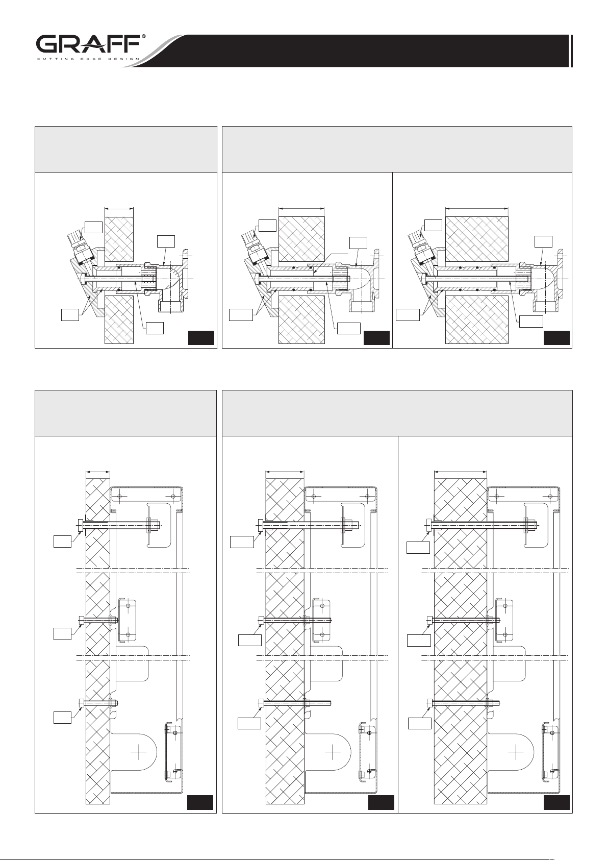
Description of hose connector assembly – see Installation Instructions no.: 2283.00 (included with Thermostatic Showering Panel) on page 14 (fig. 11).
STANDARD HOSE CONNECTOR (T17) & BOLT (T18)
For wall 25/64" (10mm) - 1" (25mm)
ACOPLAMIENTO DE LA MANGUERA ESTANDAR
Para el muro de 25/64" (10mm) - 1" (25mm)
T17
Descripción del montaje del acoplamiento de la manguera - ver Instrucción del Servicio y Montaje número 2283.00
(T17) Y EL PERNO (T18)
WALL THICKNESS
ESPESOR DEL MURO
MIN. 25/64" (10mm)
MAX. 1" (25mm)
T19
T16
T18
(adjuntada al Panel de Ducha) pag. 14 (dis. 11).
EXTENDED HOSE CONNECTOR (T17A) & BOLTS (T18A), (T18B)
ACOPLAMIENTO DE LA MANGUERA ALARGADO (T17A) Y LOS PERNOS (T18A), (T18B)
WALL THICKNESS
ESPESOR DEL MURO
MIN. 1" (25mm)
MAX. 1-37/64" (40mm)
T19
T17A
For wall 1" (25mm) - 2-11/64" (55mm)
Para el muro de 1" (25mm) -
2-11/64"
T19
T16
CUT
CORTE
T17A
(55mm)
WALL THICKNESS
ESPESOR DEL MURO
MIN. 1-37/64" (40mm)
MAX. 2-11/64" (55mm)
T18A
T16
T18B
1.1 1.2 1.3
Description of mounting screws assembly – see Installation Instructions no.: 2283.00 (included with Thermostatic Showering Panel)
Descripción del montaje de los tornillos de montaje -ver Instrucción del Servicio y Montaje número 2283.00
STANDARD MOUNTING SCREWS (R21)&(R23) SET
For wall 25/64" (10mm) - 1" (25mm)
CONJUNTO DE TORNILLOS
DE MONTAJE ESTANDAR (R21) Y (R23)
Para el muro 25/64" (10mm) - 1" (25mm)
WALL THICKNESS
ESPESOR DEL MURO
MIN. 25/64" (10mm)
MAX. 1" (25mm)
(adjuntata al Panel de Ducha) en la pag. 13 (dis. 10) y en la pag. 15 (dis. 13).
on page 13 (fig. 10) & page 15 (fig. 13).
EXTENDED MOUNTING SCREWS
CONJUNTO DE TORNILLOS DE MONTAJE ALARGADOS (R21A), (R21B) Y (R23A)
WALL THICKNESS
ESPESOR DEL MURO
MIN. 1" (25mm)
MAX. 1-37/64" (40mm)
For wall 1" (25mm) - 2-11/64" (55mm)
Para el muro 1" (25mm) - 2-11/64" (55mm)
(R21A), (R21B) & (R23A) SET
WALL THICKNESS
ESPESOR DEL MURO
MIN. 1-37/64" (40mm)
MAX. 2-11/64" (55mm)
R21
R23
R23
Sub-Revoqueo
El Juego Completo
Complete Rough Box Set
R21A
R23A
R23A
R21B
Sub-Revoqueo
El Juego Completo
Complete Rough Box Set
R23A
Sub-Revoqueo
El Juego Completo
Complete Rough Box Set
R23A
2.1 2.2 2.3
IOG 2284.70 Rev. 1 July 2008
2
Page 3
EXTENSION KIT for Wall-Mounted Thermostatic Showering Panel
JUEGO DE EXTENSIÓN para Panel de Ducha para Montar en la Pared
Installation Instructions ● Instrucciones de Instalación
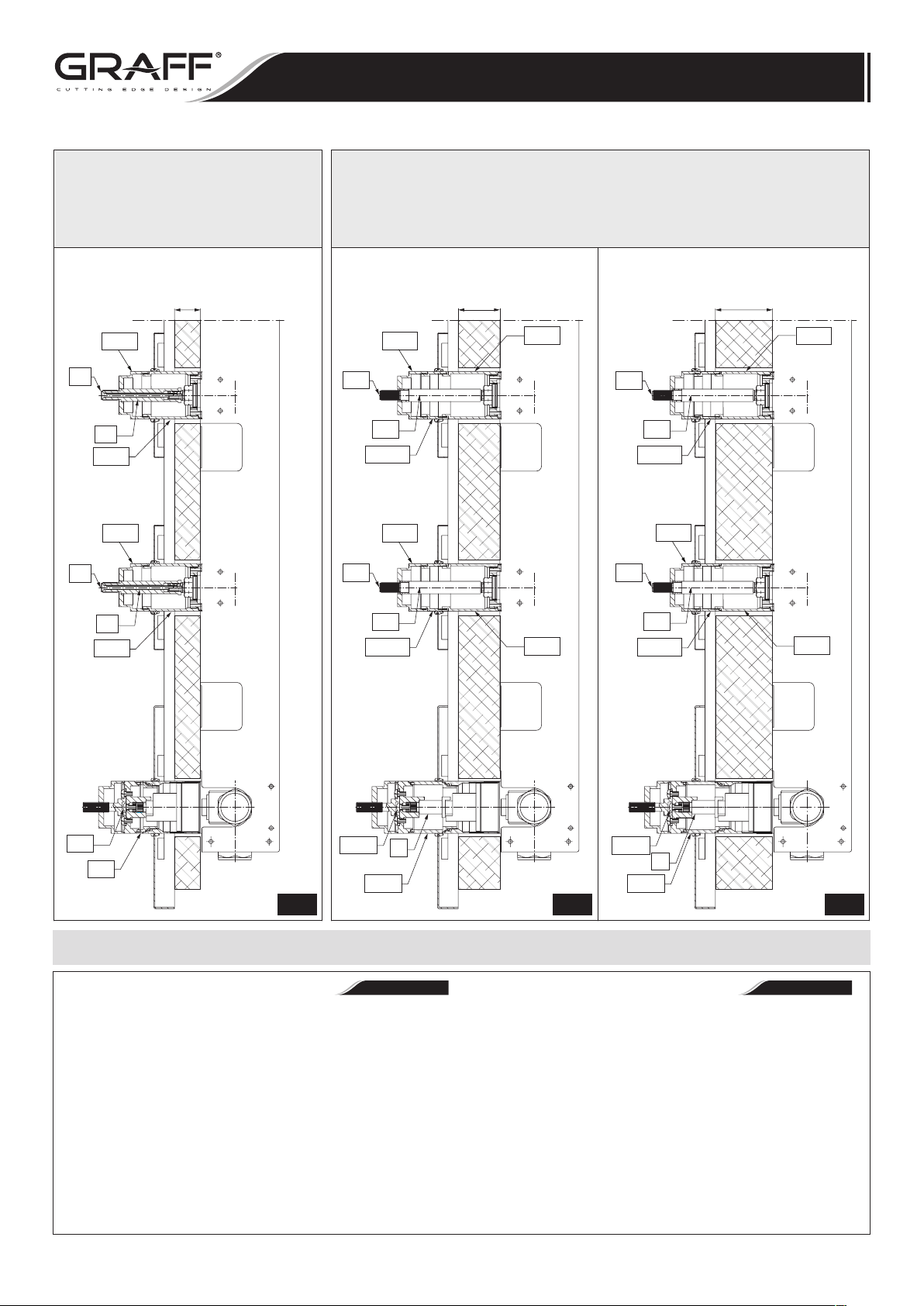
STANDARD STOP/VOLUME CONTROL VALVE
& THERMOSTATIC VALVE TRIMS
For wall 25/64" (10mm) - 1" (25mm)
LOS ACABADOS DE LA VÁLVULA
REGULADORA DE CIERRE Y DE LA VÁLVULA
TERMOSTÁTICA ESTANDAR
Para el muro 25/64" (10mm) - 1" (25mm)
WALL THICKNESS
ESPESOR DEL MURO
MIN. 25/64" (10mm)
MAX. 1" (25mm)
T14.2
R7
R6
T14.1
T14.2
Complete Rough Box Set
R7
El Juego Completo Sub-Revoqueo
R7A
R7A
EXTENDED STOP/VOLUME CONTROL VALVE & THERMOSTATIC VALVE TRIMS
LOS ACABADOS DE LA VÁLVULA REGULADORA DE CIERRE
WALL THICKNESS
ESPESOR DEL MURO
MIN. 1" (25mm)
MAX. 1-37/64" (40mm)
T14.2
For wall 1" (25mm) - 2-11/64" (55mm)
Y DE LA VÁLVULA TERMOSTÁTICA ALARGADOS
Para el muro 1" (25mm) - 2-11/64" (55mm)
WALL THICKNESS
ESPESOR DEL MURO
MIN. 1-37/64" (40mm)
MAX. 2-11/64" (55mm)
T14.1
R7A
R6A
T14.1A
T14.2
Complete Rough Box Set
El Juego Completo Sub-Revoqueo
R6A
T14.1A
T14.2
R7A
T14.1
Complete Rough Box Set
El Juego Completo Sub-Revoqueo
T6.1A
R6A
T14.1A
A
R6
T14.1
T6.1
T3.1
T3.1A
3.1 3.2 3.3
INSTALACIÓN DE LA JUEGO DE EXTENSIÓN (con Válvula Termostática 3/4”)
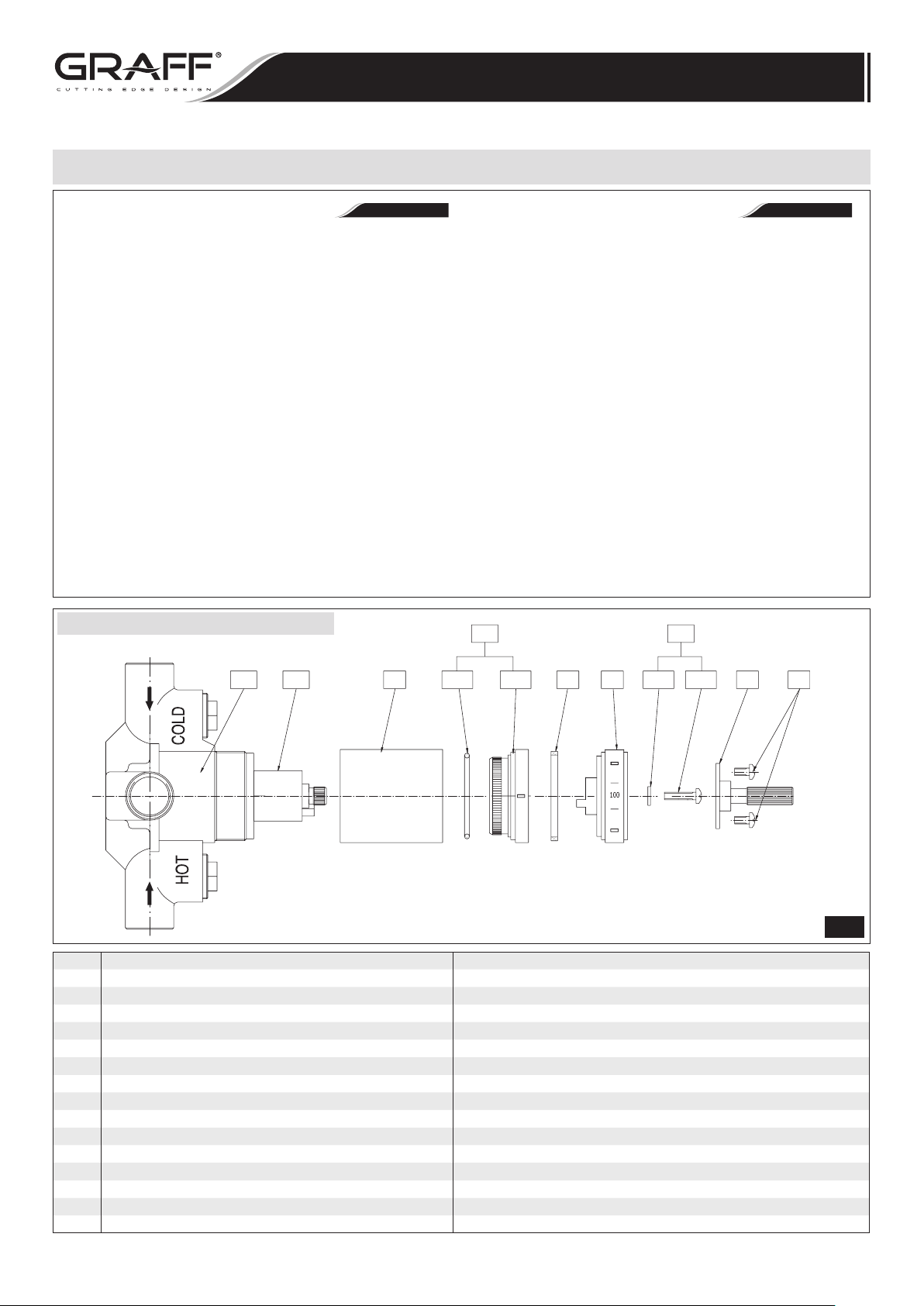
1. Remove the screws (T18) and dismantle the adapter
(T7).
2) Remove the screw
the temperature scale dial
3) Remove the indicator ring
note that the o-ring
indicator ring (T3.1).
4) Remove Teflon
®
slip ring (T4) from the indicator ring
(T3.1) and insert it into the identical seat in extended
indicator ring (T3.1A).
5) Remove o-ring
(T3.2) from the indicator ring (T3.1) and
insert it into the identical groove in extended indicator ring
(T3.1A).
NOTE: Do not dismantle the temperature limit ring (R12)
and sleeve
(T2).
EXTENSION KIT (for 3/4” Thermostatic Valve) INSTALLATION
(T6.1) with washer (T6.2) and take
(T5) from the spline (S1).
(T3.1) from the sleeve (T2),
(T3.2) - should be in the groove of
R6A
T14.1
T14.1A
T14.1
T6.1A
A
T3.1A
ESPAÑOLENGLISH
1) Sacar los tornillos (T18) y desmontar el conector (T7).
2) Sacar el tornillo
la polichaveta
3) Sacar el indicador
ción en el anillo
el indicador (T3.1).
4) Sacar el anillo de corredera de Teflón
(T6.1) con la arandela (T6.2) y quitar de
(S1) la escala (T5).
(T3.1) del casquillo (T2), fijar la aten-
(T3.2) - debe quedar en la muesca sobre
®
(T4) del indicador
(T3.1) y colocarlo en un nido idéntico en el indicador de
distancia (T3.1A).
5) Sacar el anillo
(T3.2) del indicador (T3.1) y colocar-
lo en la muesca idéntica sobre el indicador de distancia
(T3.1A).
NOTA: No desmontar el limitador (R12) ni el casquillo (T2).
IOG 2284.70 Rev. 1 July 2008
3
Page 4
EXTENSION KIT for Wall-Mounted Thermostatic Showering Panel
JUEGO DE EXTENSIÓN para Panel de Ducha para Montar en la Pared
Installation Instructions ● Instrucciones de Instalación
INSTALACIÓN DE LA JUEGO DE EXTENSIÓN (con Válvula Termostática 3/4”)
6) See fig. 4.2: Insert the extended indicator ring (T3.1A)
onto sleeve
sitioned as on the fig. 4.2.
the spline is allowed.
7) See fig. 4.3: Insert the temperature scale dial
the spline
limiting block
and limiting block
one axis with each other.
the spline is allowed.
8) See fig. 4.4: Insert the temperature scale dial
stem extension
ing „100” setting on the dial (T5) with the same axis of
the marker
9) Secure the dial
extension kit with the washer
screw (T6.1A) too hard. Check if the dial (T5) turns
properly.
10) Fasten the spline adapter
screws (T8).
11) Check the water temperature at the outlet from the valve.
Please follow the water temperature setting guidelines
from the Assembly Instructions no.: 2283.00 in case the
water temperature needs to be adjusted.
(T2) in such way, so the marker (M) is po-
(S2) stem extension (A) making sure that the
(E1) of the temperature scale dial (T5)
(A) onto spline (S1) of valve stem align-
(M) sign: „®” .
(T5) with the screw (T6.1A) from the
EXTENSION KIT (for 3/4” Thermostatic Valve) INSTALLATION
NOTE: An offset of 1 tooth on
(T5) onto
(E2) of the stem extension (A) are in
NOTE: An offset of 1 tooth on
(T5) with
(T6.2). Do not fasten the
(T7) to the dial (T5) using the
ESPAÑOLENGLISH
6) Vea fig. 4.2: Colocar el indicador de distancia
sobre el casquillo
la posición presentada en la fig. 4.2.
desplazamiento por 1 diente en la polichaveta.
7) Vea fig. 4.3: Poner la escala
(S2) de la extensión (A) así que el limitador (E1) de la
escala (T5) y el limitador (E2) de la extensión (A) estén
en el mismo eje.
1 diente en la polichaveta.
8) Vea fig. 4.4: Colocar la escala
en la polichaveta
la cifra „100” en la escala
el marcador (M) marcado „®” (que esté en frente del
marcador).
9) Fijar la escala
de extensión con la arandela
(T6.1A) demasiado fuerte, verificar si la escala gira bien
(T5).
10) A la escala
(T8).
11) Verificar la temperatura del agua saliendo; si la tempera
tura no es buena hay que realizar la regulación según la
Instrucción del Servicio y Montaje número 2283.00.
(T2) así que el marcador (M) esté en
NOTA: Se admite el
(T5) sobre la polichaveta
NOTA: Se admite el desplazamiento por
(T5) con la extensión (A)
(S1) del vástago de la válvula, así que
(T5) esté en el mismo eje que
(T5) con el tornillo (T6.1A) del juego
(T6.2). No fijar el tornillo
(T5) fijar el conector (T7) usando los tornillos
(T3.1A)
-
TOP VIEW • VISTA DELANTERA
TOP VIEW * VISTA DELANTERA
R9
R9 THERMOSTATIC VALVE VÁLVULA TERMOSTÁTICA
R12 TEMPERATURE LIMITING RING ANILLO LIMITADOR DE TEMPERATURAS
T2 SLEEVE CASQUILLO
T3.1 INDICATOR RING ANILLO INDICADOR
T3.2 O-RING SEAL SELLADOR DE ANILLO
T4 TEFLON SLIP RING ANILLO DE CORREDERA DE TEFLON
T5 TEMPERATURE SCALE DIAL DISCO DE LA ESCALA DE TEMPERATURAS
T6.1 SCREW TORNILLO
T6.2 WASHER ARANDELA
T7 SPLINE ADAPTER CONECTOR DE POLICHAVETA
T8 SHORT SCREWS (2 pieces) TORNILLOS CORTOS (2 piezas)
S1 SPLINE OF VALVE STEM POLICHAVETA DE ESPIGA DE LA VÁLVULA
S2 SPLINE OF ADAPTER SPLINE POLICHAVETA DE CONECTOR DE POLICHAVETA
E1 LIMITING BLOCK OF THE TEMPERATURE SCALE DIAL LIMITADOR EN EL DISCO DE LA ESCALA DE TEMPERATURAS
E2 LIMITING BLOCK OF THE STEM EXTENSION LIMITADOR EN LA ESPIGA DE EXTENSIÓN
M
„®” MARKER MARCADOR „®”
R12
T2
T3.2
T3
T3.1
T4 T5 T6.2 T6.1 T7 T8
T6
4.1
IOG 2284.70 Rev. 1 July 2008
4
Page 5
T14
T14.1 T14.2
R5 R6 R7
EXTENSION KIT for Wall-Mounted Thermostatic Showering Panel
JUEGO DE EXTENSIÓN para Panel de Ducha para Montar en la Pared
Installation Instructions ● Instrucciones de Instalación
T3.1A
R12
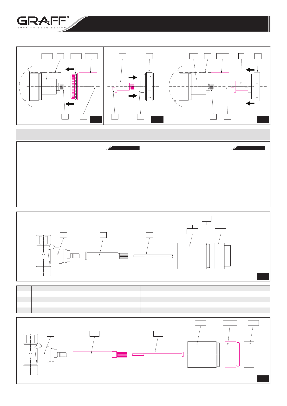
1. Remove screw (R7), take off the adapter (R6) from stem
of valve
2. Slide onto stem of valve
Insert extended screw (R7A).
3. Unscrew decorative sleeve
Screw the sleeve
the elongation sleeve
sleeve
4. Further installation steps should be done according to In
stallation Instructions no.: 2283.00 pages 14-15 (fig. 11,
13).
(R5).
(T14.2).
T3.2
T2
MS1
4.2 4.3 4.4
INSTALACIÓN DE LA JUEGO DE EXTENSIÓN (con Válvula Reguladora de Cierre)
EXTENSION KIT (for Stop/Volume Control Valve) INSTALLATION
(R5) extended adapter (R6A).
(T14.2) from sleeve (T14.1).
(T14.1) onto the valve (R5), then screw
(T14.1A) and finally the decorative
A
E2
T5
100
E1
1. Destornillar el tornillo (R7), quitar el adaptador (R6) del
husillo de la válvula (R5).
2. Sobre el husillo de la válvula
gado (R6A). Enroscar el tornillo alargado (R7A).
3. Destornillar el casquillo decorativo
(T14.1). Enroscar el casquillo (T14.1) en la válvula (R5),
luego apretar el casquillo alargado
casquillo decorativo
-
4. Los pasos siguientes de montaje ejecutar según la
ción del Servicio y Montaje número 2283.00 paginas 14-15
(dis. 11, 13).
R12 T2 T3.1A A T5
S1 M
ESPAÑOLENGLISH
(R5) poner el adaptador alar-
(T14.2) del casquillo
(T14.1A) y al finale el
(T14.2).
100
Instruc-
T14
R5 R6 R7
R5 STOP/VOLUME CONTROL VALVE VÁLVULA REGULADORA DE CIERRE
R6 ADAPTER (2 PCS.) ADAPTADOR (2 PIEZAS)
R7 SCREW (2 PCS.) TORNILLO (2 PIEZAS)
T14.1 VALVE SLEEVE (2 PCS.) CASQUILLO DE LA VÁLVULA (2 PIEZAS)
T14.2 DECORATVE SLEEVE (2 PCS.) CASQUILLO DE DECORATIVO (2 PIEZAS)
R5
R6A
R7A
T14.1 T14.2
T14.1 T14.2
5.1
R14.1A
5.2
IOG 2284.70 Rev. 1 July 2008
5
Page 6
EXTENSION KIT for Wall-Mounted Thermostatic Showering Panel
JUEGO DE EXTENSIÓN para Panel de Ducha para Montar en la Pared
Installation Instructions ● Instrucciones de Instalación
CARE AND MAINTENANCE / WARRANTY
Your Graff product is designed and engineered in accord-
•
ance with thehighest quality and performance standards.
Be sure not to damage thefinish during installation. Care
should be given to the cleaning of thisproduct. Although
its finish is extremely durable, it can be damaged byharsh
abrasives or polish. Never use abrasive cleaners, acids,
solvents,etc. to clean any Graff product. To clean,
simply wipe gently with a dampcloth and blot dry
with a soft towel.
Warranty conditions and warranty registration card are
•
outlined on a separate sheet.
HOTLINE FOR HELP • NUMERO DE EMERGENCIA
For toll-free information and answers to your questions, call:
Llame sin costo para obteiner informacion y respestas a sus preguntas:
1 - 800 - 954 - GRAF (4723)
www.graffcollection.com
CUIDADO Y MANTENIMIENTO / GARANTÍA
•
ESPAÑOLENGLISH
Su producto de la Graff esta diseñado y se regido de acuer-
•
docon los estándares de funcionamiento y calidad más al
tos. Esteseguro no dañar las terminaciones del grifo durante la instalación. Cuide el producto manteniendolo siempre
limpio. Aunque suacabado es extremadamente durable,
puede ser dañado por losabrasivos o pulientes ásperos.
Nunca utilice limpiadoresabrasivos, ácidos, solventes, el etc. para limpiar cualquier producto de la Graff.
Para limpiar, simplemente use un paño húmedo y seque con una toalla suave.
Las condiciones de la garantía y la tarjeta del registro de
•
la garantía se encuentran en una pagina separada.
-
All dimensions and drawings are for reference only. For details, please refer to actual products.
Todas las dimensiones y dibujos sirven únicamente de referencia. Para consultar detalles, ver los productos.
IOG 2284.70 Rev. 1 July 2008
6
 Loading...