

Page 1
IOG 2828.60
1
8050
7058
8051
Model
Modelo
Model
Modelo
Model
Modelo
Installation Instructions Instrucciones de Instalación
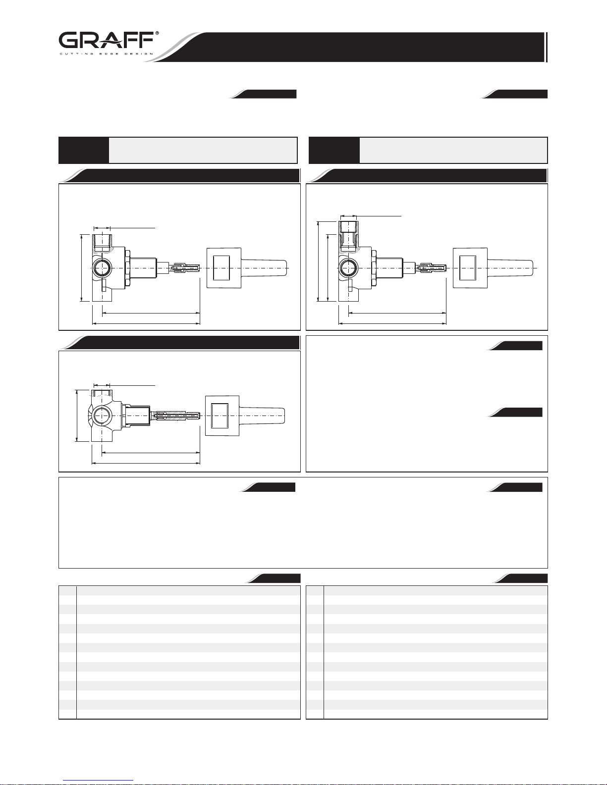
4 - WAY VALVES
VÁLVULAS DE 4 VÍAS
4-Ways Transfer Valve HF With OFF function
VÁLVULAS DE 4 VÍAS con OFF
4-Way Transfer Valve LF Without OFF function
VÁLVULAS DE 4 VÍAS sin OFF
4-Way Transfer Valve HF Without OFF function
VÁLVULAS DE 4 VÍAS sin OFF
~
ESPANOL
~
ESPANOL
ENGLISH
ENGLISH
➠The following tools need to be available for the installation:
1/2" nominal coupling,
monkey wrench,
adjustable spanner,
flat screwdriver,
metal saw or a pipe cutting tool,
thread sealant (e.g. Teflon film).
➠ PRODUCT DESCRIPTION
4-way distributing valves are designed to adjust the water flow in a
selected receiver.
The products are equipped with brass ½-14NPT studs with internal
threads.
➠ Para la instalación son necesarios las herramientas
siguientes:
racores nominales 1/2",
llave de mordaza,
llave ajustable,
destornillador plano,
sierra para metales o cortadora para tubos,
sellador de la rosca, ejm.: cinta de teflón.
➠ DESCRIPCIÓN DEL PRODUCTO
Válvulas de 4 vías de distribución sirven para ajustar la salida del
agua en el tipo de receptor escogido.
Los productos están dotados en racores ½-14NPT con rosca interna,
hechos de latón.
Dear Customer Estimado Cliente
Thank you for selecting our product. We are confident we can fully satisfy Muchas gracias por elegir nuestro producto. Estamos seguros que podemos
your expectations by offering you a wide range of technologically advanced satisfacer completamente sus expectativas ofreciéndole una amplia variedad
products which directly result from our many years of experience in faucet de productos tecnológicamente avanzados que resultan directamente de
and fitting production. muchos años de experiencia en grifos y su producción apropiada.
ENGLISH
~
ESPANOL
ENGLISH
~
ESPANOL
R1
R2
R3
R4
R5
R6
T1
T2
T3
T4
T5
T6
T7
A
R1
R2
R3
R4
R5
R6
T1
T2
T3
T4
T5
T6
T7
A
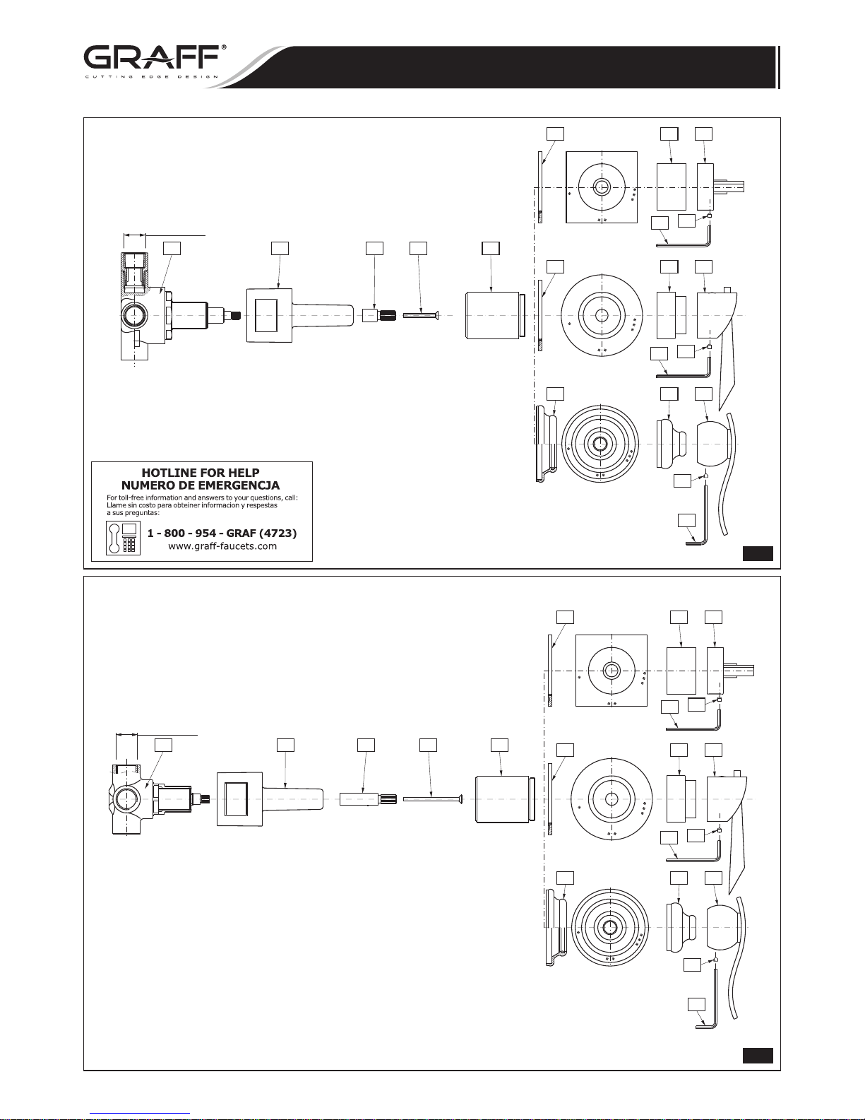
4-WAY VALVE
4-WAY VALVE
4-WAY VALVE
COVER
VALVE SPINDLE EXTENSION
SCREW / BOLT
SLEEVE
4-WAY VALVE ESCUTCHEON
4-WAY VALVE ESCUTCHEON
4-WAY VALVE ESCUTCHEON
VALVE COVER
LEVER (HANDWHEEL)
FIXING BOLT
ALLEN KEY
VÁLVULA DE 4 VÍAS
VÁLVULA DE 4 VÍAS
VÁLVULA DE 4 VÍAS
PROTECCIÓN DE MONTAJE
EL TUBO DE PROLONGACIÓN DEL HUSILLO DE LA VÁLVULA
TORNILLO
CASQUILLO
ROSETA PARA LA VÁLVULA DE 4 VÍAS
ROSETA PARA LA VÁLVULA DE 4 VÍAS
ROSETA PARA LA VÁLVULA DE 4 VÍAS
PROTECCIÓN DE LA VÁLVULA
PALANCA (VOLANTE)
TORNILLO DE SUJECIÓN
LLAVE ALLÉN
For care, use soft towel with soap and water only! Under no
circumstances should you use any chemicals.
ATTENTION!
ATENCIÓN!
Para el cuidado, utilice solamente una toalla suave con jabón
y aqua! Bajo ninguna circunstancia no use productos químicos.
5-1/16"
(128.4mm)
5-9/16" (141.4mm)
3-1/2"
(88mm)
1/2-14NPT
WALL MIN.
WALL MAX.
5-1/16"
(128.4mm)
5-9/16" (141.4mm)
4-1/8"
(105.5mm)
3-1/2"
(88mm)
1/2-14NPT
WALL MIN.
WALL MAX.
5-1/16"
(128.4mm)
5-9/16"
(141.4mm)
2-11/16"
(68mm)
1/2-14NPT
WALL MIN.
WALL MAX.
Rev. 4 January 2014
Page 2
IOG 2828.60
2
Installation Instructions Instrucciones de Instalación
4 - WAY VALVES
VÁLVULAS DE 4 VÍAS
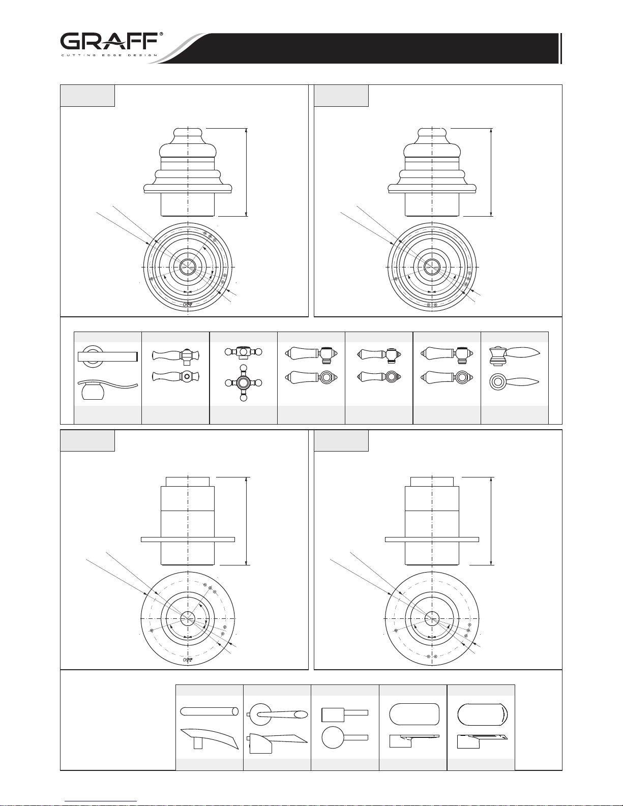
LM14S-**-T
TOPAZ
LC1S-**-T
CANTERBURY
& NUNTUCKET
LM34S-**-T
CANTERBURY
& NUNTUCKET
LM15S-**-T
NUNTUCKET
C2S-**-T
CANTERBURY
& NUNTUCKET
LM22S-**-TLM20S-**-T
LAUREN
BALI
72°
Ø2-9/16"
(Ø65mm)
Ø
Ø
3-1/8"
(
85mm)
72°
3"
(~75,3mm)
Ø2-9/16"
(Ø65mm)
72°
Ø3" (Ø75mm)
72°
~3" (75,3mm)
Ø2-9/16"
(Ø65mm)
72°
72°
Ø3"
(Ø75mm)
72°
~3" (75,3mm)
72°
Ø2-9/16"
(Ø65mm)
Ø Ø
3-1/8"
(
85mm)
72°
72°
3"
(~75,3mm)
8060
8063
8061
8064
4-Ways Transfer Valve HF With OFF function
(Trim Only Without Handle)
VÁLVULAS DE 4 VÍAS con OFF
(Sólo el Acabado de la VÁLVULA sin el Manecilla)
4-Ways Transfer Valve HF With OFF function
(Trim Only Without Handle)
VÁLVULAS DE 4 VÍAS con OFF
(Sólo el Acabado de la VÁLVULA sin el Manecilla)
4-Way Transfer Valve HF Without OFF function
(Trim Only Without Handle)
VÁLVULAS DE 4 VÍAS sin OFF
(Sólo el Acabado de la VÁLVULA sin el Manecilla)
4-Way Transfer Valve HF Without OFF function
(Trim Only Without Handle)
VÁLVULAS DE 4 VÍAS sin OFF
(Sólo el Acabado de la VÁLVULA sin el Manecilla)
Types of Handles use with 8060, 8061: Tipos de manecillas usadas con el modelo 8060, 8061:
Types of Handles use with 8063, 8064: Tipos de manecillas usadas con el modelo 8063, 8064:
LM-37S-**-T LM-42S-**-T
M.E. & M.E.25
LM-25B-**-T
LM-24S-**-T
ATRIA SENTO
TRANQUILITY
LM-45S-**-T
PHASE
Rev. 4 January 2014
Page 3
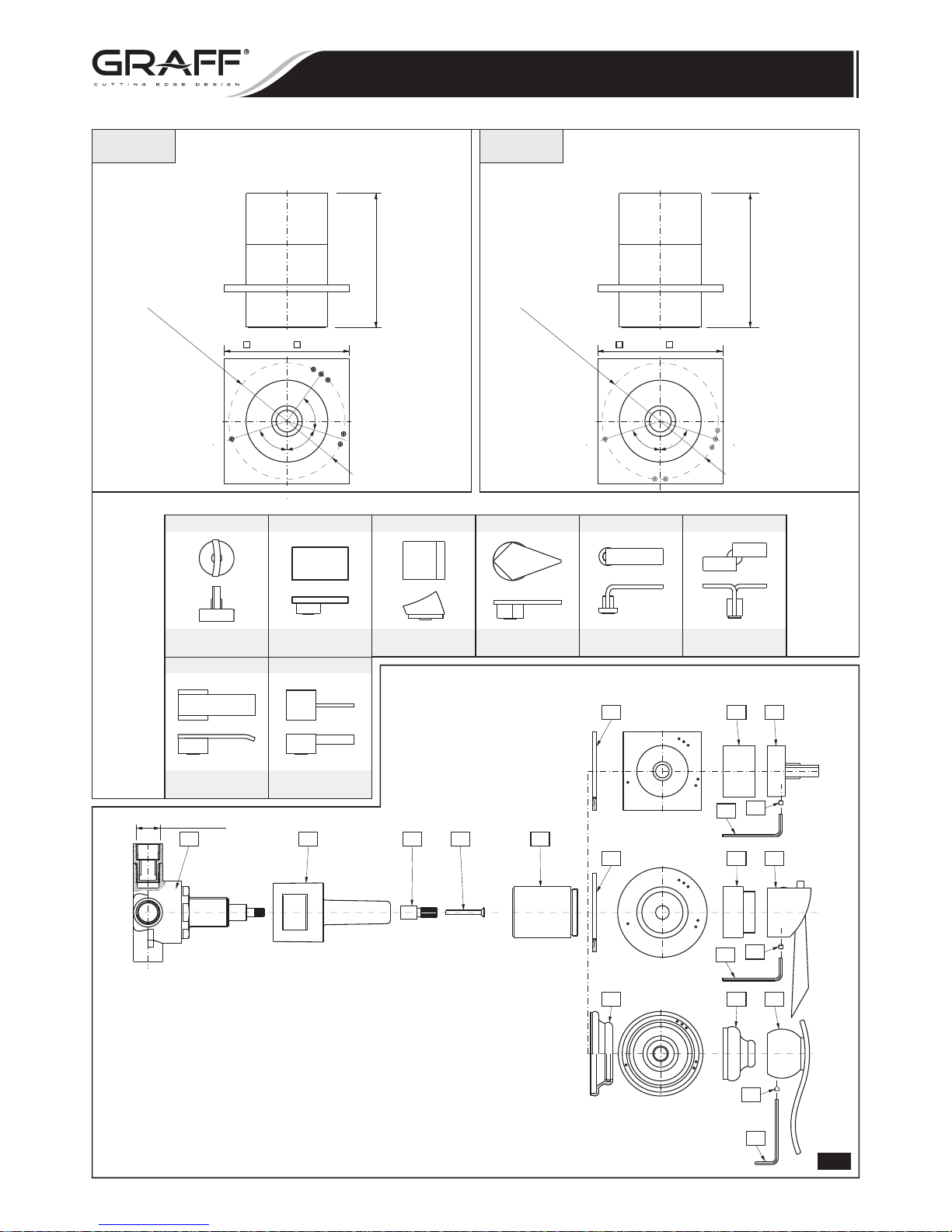
C10S-**-T
FONTAINE
LM23S-**-T
STEALTH
LM31S-**-TC14S-**-T
SOLAR
& STRUCTURE
LUNA, SADE,
TARGA
C9S-**-T
IMMERSION
LM40S-**-T
IMMERSION
LM38S-**-T LM39S-**-T
QUBIC
QUBIC TRE
IOG 2828.60
3
Installation Instructions Instrucciones de Instalación
4 - WAY VALVES
VÁLVULAS DE 4 VÍAS
Ø2-9/16"
(Ø65mm)
2-3/4"
( 70mm)
~3"
(75,3mm)
72°
72°
Ø2-9/16"
(Ø65mm)
2-3/4"
( 70mm)
~3"
(75,3mm)
72°
72°
72°
OFF
8066 8067
4-Ways Transfer Valve HF With OFF function
(Trim Only Without Handle)
VÁLVULAS DE 4 VÍAS con OFF
(Sólo el Acabado de la VÁLVULA sin el Manecilla)
4-Way Transfer Valve HF Without OFF function
(Trim Only Without Handle)
VÁLVULAS DE 4 VÍAS sin OFF
(Sólo el Acabado de la VÁLVULA sin el Manecilla)
Types of Handles use with 8066, 8067: Tipos de manecillas usadas con el modelo 8066, 8067:
1.1
OFF
OFF
OFF
WALL MAX.
WALL MIN.
R1 R4 R5
R6 T1
T2
T3
T4
T5
T5
T5
T6
T6
T6
T7
T7
T7
A
A
A
1/2-14NPT
4-Ways Transfer Valve HF With OFF function G-8050
Rev. 4 January 2014
Page 4
R3 R4 R5
R6 T1
WALL MAX.
WALL MIN.
T2
T3
T4
T5
T5
T5
T6
T6
T6
T7
T7
T7
A
A
A
1/2-14NPT
IOG 2828.60
4
1.2
R2 R4 R5
R6 T1
WALL MAX.
WALL MIN.
T2
T3
T4
T5
T5
T5
T6
T6
T6
T7
T7
T7
A
A
A
1/2-14NPT
4-Way Transfer Valve HF Without OFF function G-8051
Installation Instructions Instrucciones de Instalación
4 - WAY VALVES
VÁLVULAS DE 4 VÍAS
1.3
4-Way Transfer Valve LF Without OFF function G-7058
NOTE! For Trim Only ordering please add „T” at the end of model no., e.g. C10S-**-T
** - finish code, e.g. PC, PN, OBTM…
Finish/color code must be specified when ordering.
NOTA! Pidiendo Sólo el Acabado pongan la „T” al final del número de modelo, e.e. C10S-**-T
** - el código del acabd, e.e. PC, PN, OBTM…
Se debe especificar el codigo del acaba do/color con el pedido.
Rev. 4 January 2014
Page 5
IOG 2828.60
5
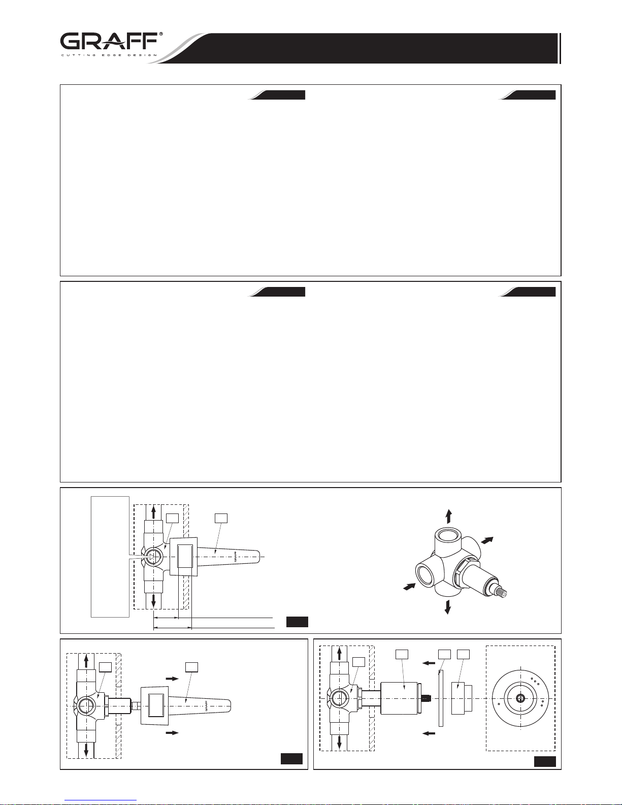
WALL MOUNTING OF THE 4 WAY VALVES - Fig. 3.1
1) Make a wall recess to install the valve, however taking into
consideration the minimum and maximum depth of the opening for
inserting the valve. Put the valve (R1) together with the extension
(R5) and the cover (R4) in the recess. Recommended depth of placing
the valve measured from the valve axis to the surface of the finishing
wall ranges from 1-3/8” (35 mm) (WALL MIN) to 2-1/8” (55 mm)
(WALL MAX).
2) Connect the mixed water supply to the entry stud marked with an
arrow. Connect the receivers (the shower head, shower set, side
nozzle set or the tub spout) to the remaining studs. The 4-way valves
are equipped with 3 outlets.
Check for any leaks and missing parts. Shut off the water supply and
complete the finishing wall.
NOTE! The sub plaster installations require pipes and fittings of
½“diameter minimum. Smaller diameters will significantly reduce
the water volume running through the valve.
INSTALLING DECORATIVE ELEMENTS AND THE LEVER
NOTE: having completed all connections, but prior to commencing
finishing works, check
for any leaks and missing parts.
1) After making the finishing wall, remove the valve installation cover
(R4).
2) Screw the sleeve (T1) onto the valve and put on the escutcheon with
the seal (T2) on the sleeve (T1). Ensure correct arrangement of the
escutcheon (T2). See Fig. 3.3. Push the escutcheon (T2) to the
finishing wall.
3) Screw the valve cover (T5) on the sleeve (T1).
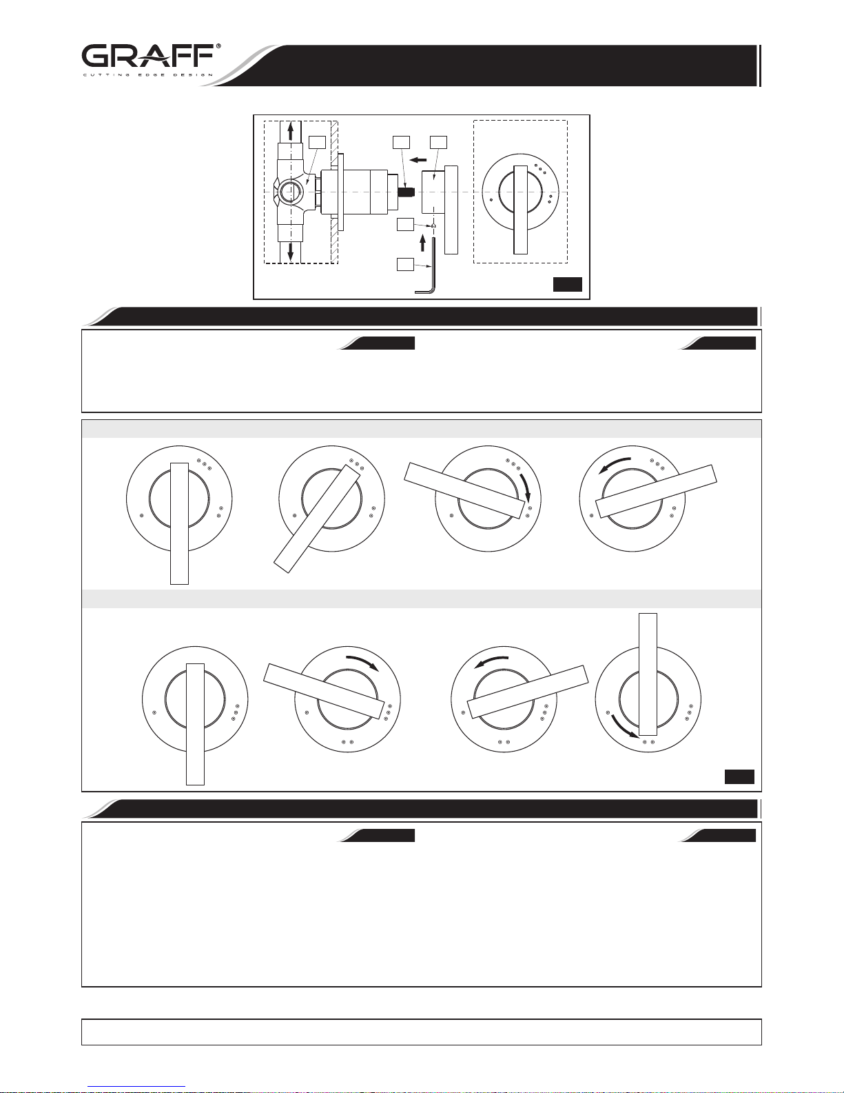
4) Turn the valve spindle extension (R5) to the extreme right position
(clockwise) and next turn backwards until a slight click can be heard.
Insert the lever (T6) on the valve spindle extension (R5) (acc. to
Fig. 3.3 and tighten the fixing bolt (T7) with the enclosed Allen
key (A).
NOTE! Types of levers (handwheels) compatible with particular 4-way
valve types are shown in Fig. 1.1-1.3.
INSTALACIÓN
DE LA VÁLVULA DE 4 VÍAS EN LA PARED - Fig. 3.1
1) Prepare un hueco en la pared para la instalación de la válvula tomando
en cuenta la profundidad máxima y mínima del montaje de la válvula.
Coloque la válvula (R1) con el tubo de prolongación (R5) y la
protección de montaje (R4) en el hueco en la pared. La profundidad
recomendada de colocar la válvula en la pared, medida desde el eje de
la válvula hasta la superficie de la pared de acabado es de 1-3/8”
(35mm) (WALL MIN.) a 2-1/8” (54mm). (WALL MAX.).
2) Conecte el agua mezclada al racor de entrada marcado con el
indicador. A los demás racores de salida conecte los receptores
(cabezal de ducha, juego de ducha, juego de boquillas laterales o caño
de bañera). Las válvulas de 4 vías están dotadas de 3 salidas.
Compruebe la estanquidad de la instalación completa. Cierre la
alimentación de agua. Realice la pared de acabado.
OJO! Para realizar la instalación bajo enlucido se deben emplear tubos
y racores del diámetro mínimo de 1/2". El empleo de tubos de
diámetro menor reducirá significativamente el caudal por la
válvula.
INSTALACIÓN DE ELEMENTOS DECORATIVOS Y PALANCAS
OJO: ntes de efectuar los trabajos de acabado y la instalación
de
elementos decorativos, tras conectar todos los tubos, asegúrese
que no hay ninguna fuga.
1) Tras realizar la pared de acabado quite la protección de montaje (R4)
de la válvula.
2) Enrosque el casquillo (T1) en la válvula y liego meta la roseta con la junta
(T2) en el casquillo (T1). Fíjese en la posición correcta de la roseta (T2)
– véase la fig. 3.3. Apriete la roseta (T2) contra la pared de acabado.
3) Enrosque la protección de la válvula (T5) en el casquillo (T1).
4) Gire el tubo de prolongación del husillo de la válvula (R5) cuanto
posible a la derecha (sentido reloj), luego gírela levemente a la
izquierda (sentido contra reloj) hasta sentir un ligero sonido de click.
Ponga la palanca (T6) en el tubo de prolongación del husillo de la
válvula (R5) según la fig. 3.3. y apriete el tornillo de sujeción (T7) con
la llave allén (A) adjunto al juego.
OJO
! Tipos de palancas (volantes) que funcionan con cada tipo de
válvulas de 4 vías se presentan en la fig. 1.1-1.3.
~
ESPANOL
~
ESPANOL
ENGLISH
ENGLISH
Installation Instructions Instrucciones de Instalación
4 - WAY VALVES
VÁLVULAS DE 4 VÍAS
3.1
4-way valve • Válvula de 4 vías
Shower head
Cabezal de ducha
Side body spray set
Juego de boquillas laterales
Tub spout
Caño de bañera
Mixed water inlet
Entrada del agua mezclada
R3 R4
WALL MAX.
WALL MIN.
MAX.2-1/8"
(MAX.54mm)
MIN.1-3/8"
(MIN.35mm)
Water supply (from a thermostatic
or a PBV valve)
Alimentación (de la válvula termostática
o de la válvula tipo PBV)
3.2
3.3
OFF
R3
T1 T2 T5
R3 R4
WALL MAX.
WALL MIN.
Rev. 4 January 2014
Page 6
IOG 2828.60
6
ENGLISH
~
ESPANOL
OPERATING INSTRUCTION • INSTRUCCIÓN DE USO
Receiver selection is made by turning the lever (handwheel) in the desired
direction – to the markings on the escutcheon. Moving the lever
(handwheel) to the position presented in Fig. 4 will cut off the water flow –
valve “closed”.
La selección del tipo de receptor se debe hacer girando la palanca (el
volante) en las posiciones escogidas, marcadas en la roseta. Girar la
palanca (el volante) a la posición conforme con la fig. 4 cierra la salida del
agua – la válvula en la posición “cerrada”.
3.4
R3 R5 T6
T7
A
Installation Instructions Instrucciones de Instalación
4 - WAY VALVES
VÁLVULAS DE 4 VÍAS
All dimensions and drawings are for reference only. For details, please refer to actual products.
Todas las dimensiones y dibujos sirven únicamente de referencia. Para consultar detalles, ver los productos.
4
4-WAY TRANSFER VALVE LF WITHOUT OFF FUNCTION • VÁLVULAS DE 4 VÍAS SIN OFF
4-WAYS TRANSFER VALVE HF WITH OFF FUNCTION • VÁLVULAS DE 4 VÍAS CON OFF
ENGLISH
~
ESPANOL
CARE AND MAINTENANCE, • CUIDADO Y MANTENIMIENTO, WARRANTY GARANTÍA
Your Graff valve is designed and engineered in accordance with the Su válvula de la Graff esta diseńado y se regido de acuerdo con los
highest quality and performance standards. Be sure not to damage the estándares de funcionamiento y calidad más altos. Este seguro no dańar las
finish during installation. Care should be given to the cleaning of this terminaciones del grifo durante la instalación. Cuide el producto
product. Although its finish is extremely durable, it can be damaged by manteniendolo siempre limpio. Aunque su acabado es extremadamente
harsh abrasives or polish. Never use abrasive cleaners, acids, durable, puede ser dańado por los abrasivos o pulientes ásperos. Nunca
solvents, etc. to clean any Graff product. To clean, simply wipe utilice limpiadores ab
rasivos, ácidos, solventes, el etc. para limpiar
gently with a damp cloth and blot dry with a soft towel. cualquier producto de la Graff. Para limpiar, simplemente use un
pańo húmedo y seque con una toalla suave.
Warranty conditions and warranty registration card are outlined on a Las condiciones de la garantía y la tarjeta del registro de la garantía se
separate sheet. encuentran en una pagina separada.
OFF OFFOFF
Rev. 4 January 2014
 Loading...