

Page 1
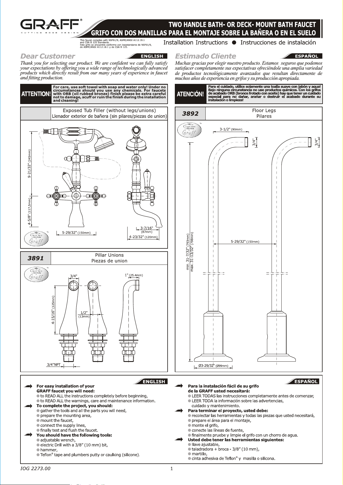
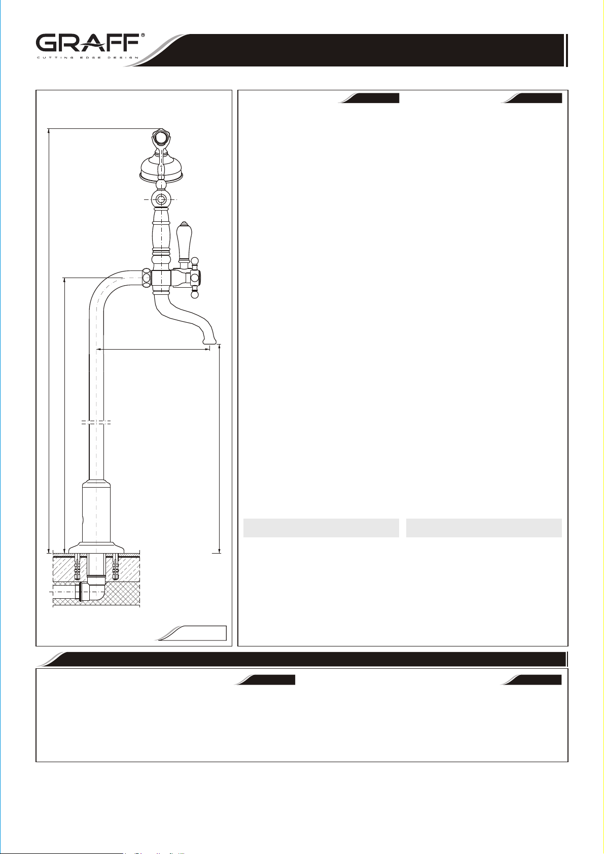
3852-C2
3853-C2
Rev. 3 October 2017
Page 2
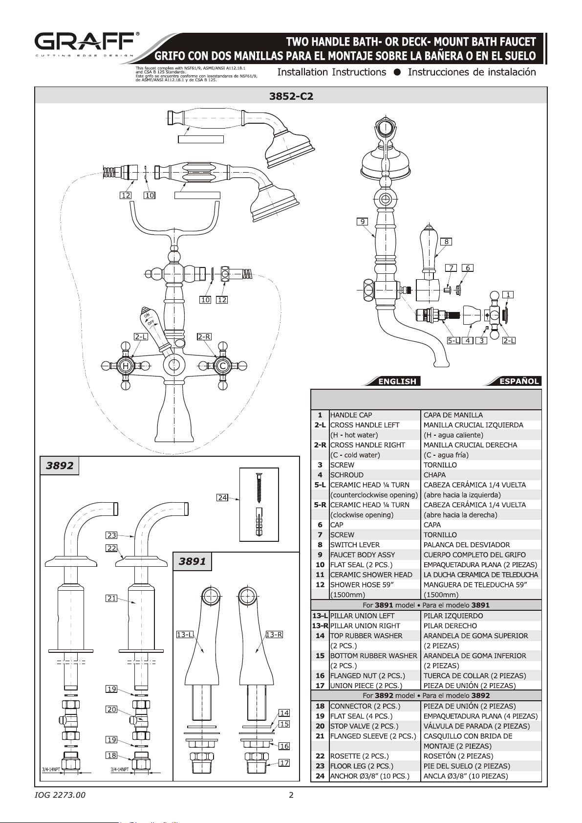
11-3853-C2
11-3852-C2
/3853-C2
For 3852-C2, 3853-C2 models
Para el modelo 3852-C2, 3853-C2
Rev. 3 October 2017
Page 3
TWO HANDLE BATH- OR DECK- MOUNT BATH FAUCET
GRIFO CON DOS MANILLAS PARA EL MONTAJE SOBRE LA BAÑERA O EN EL SUELO
This faucet complies with NSF61/9, ASME/ANSI A112.18.1
and CSA B 125 Standards.
Este grifo se encuentra conforme con losestandares de NSF61/9,
de ASME/ANSI A112.18.1 y de CSA B 125.
PRODUCT DESCRIPTION l DESCRIPCIÓN DEL PRODUCTO
ENGLISH
The Exposed Tub Filler can be installed as a deck mount filler or as a free Llenador exterior de bañera puede montarse en el borde de la bañera o
standing installation. sea como elemento destacado en el piso.
For a deck-mount installation you will need to install pillar unions En caso de la instalación en el borde de la bañera necesita instalar
3891 which are available separately. piezas de union 3891, disponibles a parte.
For a free standing installation a purchase of floor legs 3892 is En caso del montaje en le piso como elemento destacado tiene quo
required. comprar unos pilares de suelo 3892.
NOTE: Follow only the steps that apply to your installation. ATENCIÓN: Escoja para el montaje solo los pasos correspondientes a su
ENGLISH
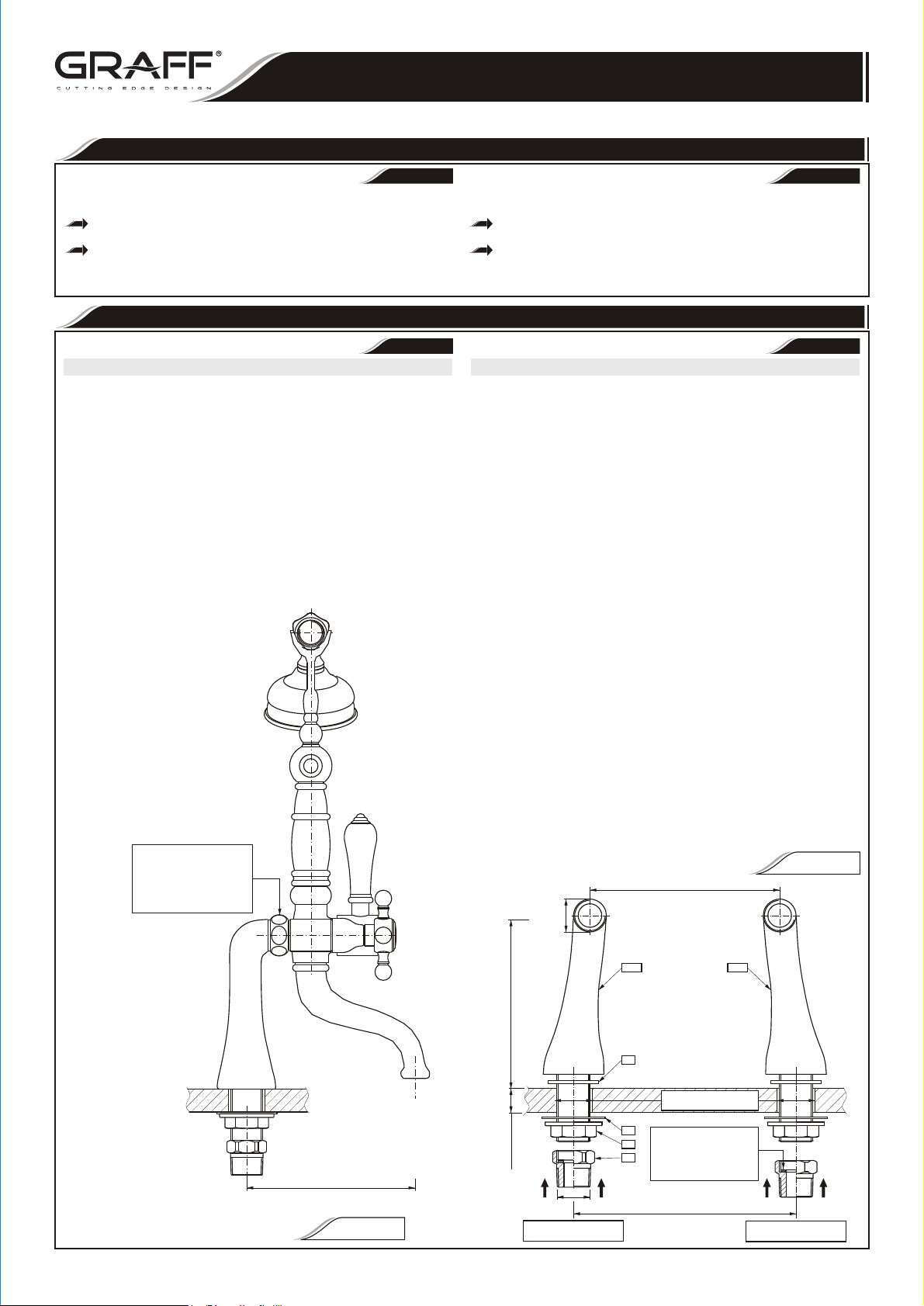
Deck-Mount Installation (using pillar unions 3891) Montaje en el borde de la bañera (usando las piezas de union 3891)
1. Prepare two holes on the tub rim / deck. The holes should be spaced 1. Prepare dos agujeros de montaje en el borde de la bañera. Los
6-59/64” (176 mm) between the centers and the diameter of the hole agujeros deben situarse en distancia 6-59/64” (176 mm), el diametro
should be between 1-1/8” and 1-3/8” (29 to 35 mm) (fig. 1.1). del agujero debe ser entre 1-1/8” y 1-3/8” (29 to 35 mm) (dis. 1.1).
2. Place the pillar unions (13-L and 13-R) with the washers (14) in the 2. En los agujeros de montaje en el borde de la bañera meta de arriba
holes from the top of the rim. las piezas de union (13-L y 13-R) con arandelas (14).
3. From underneath the ledge put the washers (15) onto the threaded of 3. Por debajo del borde ponga las arandelas (15) sobre las piezas de
the pillar unions. Position the pillars so the spacing between the faucet union roscadas. Posicione las piezas de union asi que la distancia
outlets is 5-29/32” (150 mm). Hand-tighten the bottom nuts (16). entre las piezas de unión de salida piezas sea de 5-29/32” (150 mm).
4. Make sure that the flat seals are positioned correctly in the nuts in the Apriete a mano las tuercas inferiores (16).
back of the filler. Secure the filler by tightening the nuts to the pillar 4. Asegurese que las juntas planas estén posicionadas bien en las
unions (fig. 1.2). tuercas en la parte posterior del grifo de la bañera. Sujete el grifo
5. After connection of the filler to the pillar unions make sure that all the enroscando las tuercas en las piezas de unión de salida (dis. 1.2).
connections are tight and the filler is positioned correctly on the bathtub. 5. Cuando conecte el grifo de la bañera a las piezas de union, asegúrese
6. Tighten the bottom nuts (16) in the unions, connect the 3/4” que todas las conexiones estén apreitadas bien y que el grifo esté
adapters (17) if required /taking care that flat seals are positioned posicionado correcatmente sobre la bañera.
correctly/ and make connections to the water supply lines. 6. Apriete las tuercas inferiores (16) en las piezas de union, enrosque
Installation Instructions l Instrucciones de instalación
~
ESPANOL
instalación.
INSTALLATION l INSTALACIÓN
~
ESPANOL
los adaptadores (piezas de unión) 3/4” (17), si es necesario,
prestando atención a la posición correcta de las juntas planas y
conecte la instalación suministradora del agua.
IOG 2273.00
ATTENTION:
TAKING CARE THAT THE FLAT SEAL
IS POSITIONED CORRECTLY IN THE NUT
ATENCIÓN:
FIJE SU ATENCIÓN A QUE
LA JUNTA PLANA ESTE BIEN COLOCADA
EN LA TUERCA
5-5/8" (142mm)
FIG. 1.1
FIG. 1.2
5-29/32" (150mm)
3/4"
13-L 13-R
5" (126mm)
(MAX 38mm)
MAX. 1-1/2"
HOT WATER INLET
ENTRADA DE AGUA CALIENTE
3
3/4"NPT
14
MIN.Ø1-1/8"(Ø29mm)
MAX.Ø1-3/8"(Ø35mm)
15
ATTENTION:
TAKING CARE THAT THE FLAT SEAL
16
IS POSITIONED CORRECTLY
17
ATENCIÓN:
FIJE SU ATENCIÓN A QUE
LA JUNTA PLANA ESTE BIEN COLOCADA
6-59/64" (176mm)
COLD WATER INLET
ENTRADA DE AGUA FRÍA
Rev. 3 October 2017
Page 4
TWO HANDLE BATH- OR DECK- MOUNT BATH FAUCET
GRIFO CON DOS MANILLAS PARA EL MONTAJE SOBRE LA BAÑERA O EN EL SUELO
This faucet complies with NSF61/9, ASME/ANSI A112.18.1
and CSA B 125 Standards.
Este grifo se encuentra conforme con losestandares de NSF61/9,
de ASME/ANSI A112.18.1 y de CSA B 125.
18 18
Installation Instructions l Instrucciones de instalación
5-29/32" (150mm)
min. 1-11/32" (34mm)
max. 1-17/32" (39mm)
FINISHED FLOOR
ACABADO DEL SUELO
23
21
23
21
min. 2-3/4" (70mm)
3
- /
°
2
7
2
Ø
7
Ø
(
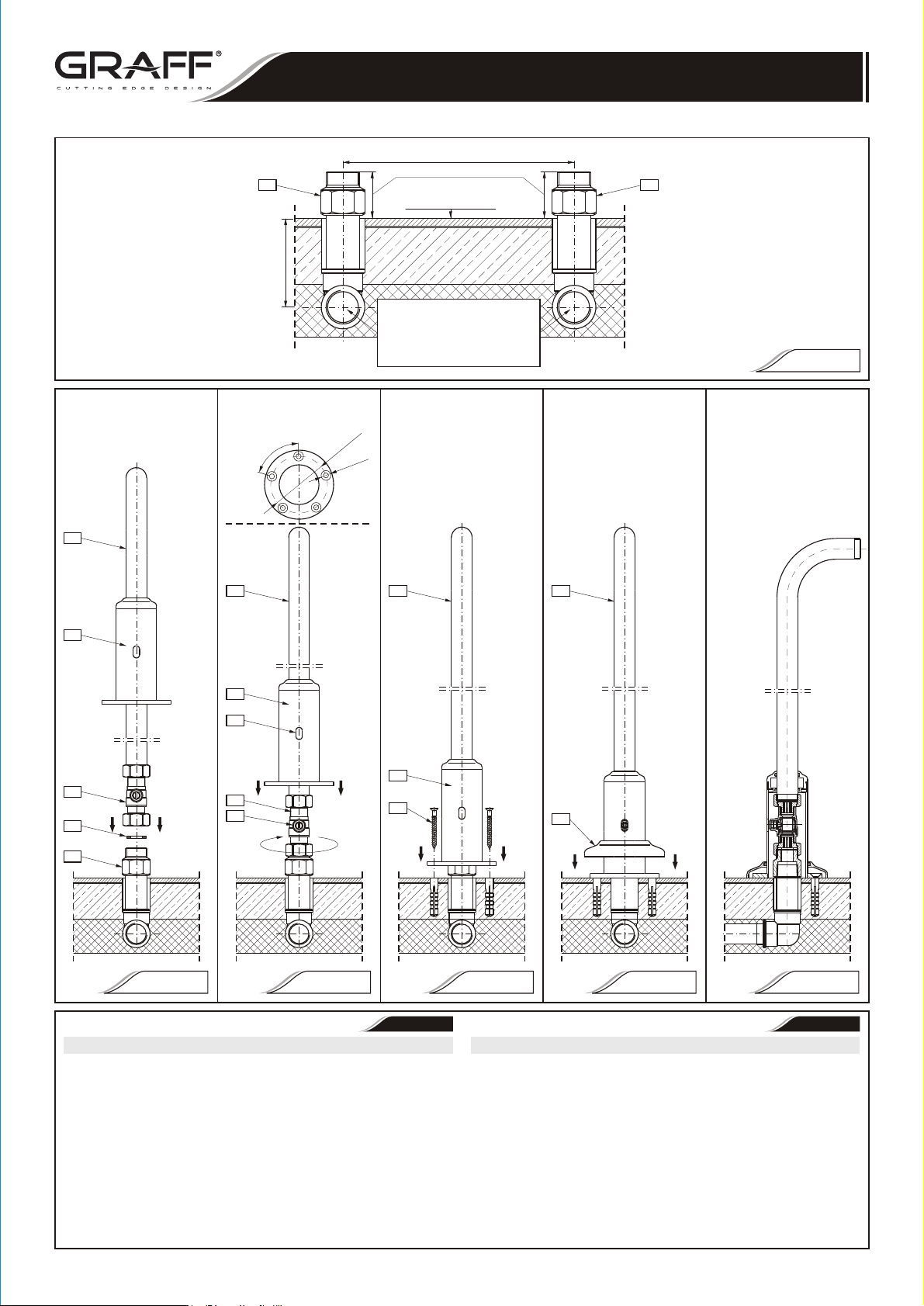
WATER SUPPLIES (HOT & COLD WATER)
NOTE: TAKING CARE THAT THE HOT WATER SUPPLY
SHOULD BE AT THE LEFT SIDE OF FRONT BATH FAUCET
SUMINISTRO DE AGUA (AGUA CALIENTE Y FRÍA)
NOTA: PRESTE ATENCIÓN DE QUE EL SUMINISTRO DEL
AGUA CALIENTE SE ENCUENTRE A LA IZQUIERDA EN
RESPECTO A LA VISTA FRONTERA DEL GRIFO DE BAÑERA.
"
4
m)
m
0
"
4
/
Ø1
)
x
m
5
m
2
.
6
Ø
x
5
(
23
FIG. 2
23
A
21
20
19
20
B
24
22
18
FIG. 3.1 FIG. 3.2 FIG. 3.3 FIG. 3.4 FIG. 3.5
ENGLISH
Free Standing Installation (using floor legs 3892) Montaje del grifo destacado (con los pilares de suelo 3892)
The floor legs can be mounted on concrete floor. Los pilares de suelo deben montarse en el hormigón.
1. Before putting the concrete floor and tiles lead the water supply 1. Antes de poner el hormigón y las tables, acople la instalación
(hot and cold) to a place where you intend to install the legs. suministradora acuática (agua caliente y fría) al puesto/lugar de
2. Set the height of the ¾” pipes in the floor to about ½” above montaje de los pilares.
finished floor with 5-29/32” (150mm) spacing between them. After 2. Establezca la altura de los tubos ¾” en el suelo unos ½” encima el nivel
checking that the water connections are tight, make the concrete del suelo acabado en la distancia 5-29/32” (150mm) /distancia entre
sub-floor securing the ¾” pipe outlets. After the sub-floor has los tubos/. Cuando controle la estanqueidad de las conexiones (que no
solidified make the finished floor. haya escapas de agua) proceda a realizar el hormigón para proteger las
3. Apply the Teflon tape onto ¾” pipe and thread the connector (18) piezas de unión iniciales de los tubos ¾”. Cuando el hormigón esté
®
- see fig. 2. seco/duro ponga la superficie de acabado del suelo.
4. Thread the mounting nut of the stop valve (20) with leg onto the 3. Enrolle la cinta de teflón en el tubo de unión del tubo ¾” y enrosque
connector (18). Make sure that the flat seal (19) is on the stop en ella la pieza de unión (18) - ver dis. 2.
valve nut then threading. Position the leg so that the top end will be 4. Apriete la tuerca de montaje de la válvula de cierre/de parada (20)
toward the bathtub (fig. 3.1). con pilar en la pieza de unión (18). Asegúrese que la
IOG 2273.00
4
ESPANOL
Rev. 3 October 2017
~
Page 5
TWO HANDLE BATH- OR DECK- MOUNT BATH FAUCET
GRIFO CON DOS MANILLAS PARA EL MONTAJE SOBRE LA BAÑERA O EN EL SUELO
This faucet complies with NSF61/9, ASME/ANSI A112.18.1
and CSA B 125 Standards.
Este grifo se encuentra conforme con losestandares de NSF61/9,
de ASME/ANSI A112.18.1 y de CSA B 125.
5. Slide down the flanged sleeve (21) by empaquetadura plana (19) esté en la
6. Lift the flanged sleeve (21) up. Drill 5 deslizándolo abajo sobre el pilar hacia el
7. Put the anchors (24) into the holes, posición correcta, como indica el diseño de
8. Put on the escutcheon plate (22) onto suelo para taladrar los orificios (dis. 3.2).
9. Repeat the steps 3-8 for other floor leg. pilares con la broca 3/8” (10mm).
10. Make sure that two legs are positioned 7. Ponga los tacos (24) en los orificios, baje y
11. Make sure that the flat seals are 8. Ponga el rosetón de adorno (22) en el
12. After connection of the filler to the floor 10. Asegúrese que los dos pilares estén
~ 8" (~203mm)
13. Put on the handles (2) onto the stem estar montado correctamente.
min. 41-47/64" (1060mm)
max. 41-59/64" (1065mm)
14. Supply water to the lines and check for el grifo apretando las tuercas en las piezas
min. 31-7/32" (793mm)
max. 31-13/32" (798mm)
min. 26-17/32" (674mm)
max. 26-47/64" (679mm)
CONNECTION OF THE SHOWER HOSE WITH
see p. 2
1. Connect the hose (12) with conical
2. Thread the other end of the hose to the
3. The diverter lever (8) is used to switch
FIG. 4
Installation Instructions l Instrucciones de instalación
~
ENGLISH
leg onto finished floor. Position the leg tuerca de la válvula de cierre en momento
correctly as shown on the drawing with de apretarla. Posicione correctamente el
sleeve hole (A) in the same axis as pilar de tal modo que la pieza de unión
stop valve stem (B). Next mark-up 5 superior esté dirigido a la bañera (dis. 3.1).
points on the floor for drilling (fig. 3.2). 5. Quite el casquillo con brida (21)
holes at each leg using 3/8” (10mm) bit. nivel del suelo acabado. Ponga el pilar en
lower and secure the flanged sleeve tal modo que el orificio (A) en el casquillo
(21) with 5 screws using Philips esté en el mismo eje con el husillo de la
screwdriver (fig. 3.3). válvula (B). Luego marque 5 puntos en el
leg, slide down the plate onto finished 6. Suba el casquillo con broda (21) hacia
floor (fig. 3.4). arriba. Taladre 5 orificios para cada de los
correctly (with the top ends toward the ajuste el casquillo con brida (21) con 5
bathtub) so the filler can be mounted tornillos con un destornillador tipo estrella
correctly. (dis. 3.3).
positioned correctly in the nuts in the pilar deslizándolo abajo hacia el suelo de
back of the filler. Secure the filler by acabado horizontal (dis. 3.4)
tightening the nuts to the floor legs 9. Repita los pasos 3-8 para otro pilar de
(fig. 4). suelo.
legs make sure that all the connections puestos correctamente (con piezas de
are tight and the filler is positioned unión superiores dirigidos hacia la bañera)
correctly on the bathtub. de tal modo que el grifo de bañera pueda
of hot and cold valves. Secure the 11. Asegúrese que las empaquetaduras planas
handles using the hex key for screw estén puestas bien en las tuercas en la
(3) - see p. 2. parte posterior del grifo de bañera. Monte
any leaks before normal operation of de union de salida de los pies (dis. 4).
faucet. 12. Cuando el grifo de bañera este acoplada a
los pies, asegúrese que todas las
conexiones estén bien apretadas y que el
grifo esté posicionado correctamente
respecto a la bañera.
13. Ponga las manilas (2) en el mandril de la
válvula del agua caliente y fria. Asegure las
manilas con los tornillos (3) con la llave
alien - ver p. 2.
14. Abre el agua suministradora y verifique el
grifo en modo de su uso regular, si no hay
escapes de agua.
SHOWER HEAD TO A FILLER
CONEXIÓN DE LA TELEDUCHA AL
GRIFO DE BAÑERA
ver p. 2
en din g to shower he ad ( 11)
remembering to insert rubber seal
(10).
faucet body remembering about the
seal (10).
the water flow between the tub spout
and the shower head.
1. Acople la manguera (12) con la tuerca
cónica a la ducha (11) recordándose de
poner la empaquetadura plana (10).
2. Enrosque otro extreme de la manguera al
cuerpo del gifo de bañera, recordándose
de poner la empaquetadura (10).
3. La palanca del desviador (8) sirve para
cambiar el flujo de agua entre el caño de
salida y el cabezal de la ducha.
ESPANOL
CARE AND MAINTENANCE l CUIDADO Y MANTENIMIENTO
~
ENGLISH
Your Graff faucet is designed and engineered in accordance with the highest Su grifo de la Graff esta diseñado y dirigido acuerdo con los estándares de
quality and performance standards. Be sure not to damage the finish during funcionamiento y calidad más altos. Este seguro no dañar las terminaciones del
installation. Care should be given to the cleaning of this product. Although its grifo durante la instalación. Cuide el producto manteniendolo siempre limpio.
finish is extremely durable, it can be damaged by harsh abrasives or polish. Aunque su acabado es extremadamente durable, puede ser dañado por los
Never use abrasive cleaners, acids, solvents, etc. to clean any Graff abrasivos o pulientes ásperos. Nunca utilice limpiadores abrasivos,
product. To clean, simply wipe gently with a damp cloth and blot dry ácidos, solventes, el etc. para limpiar cualquier producto de la Graff.
with a soft towel. Para limpiar, simple-mente use un paño húmedo y seque con una
IOG 2273.00
toalla suave.
5
ESPANOL
Rev. 3 October 2017
Page 6
TWO HANDLE BATH- OR DECK- MOUNT BATH FAUCET
GRIFO CON DOS MANILLAS PARA EL MONTAJE SOBRE LA BAÑERA O EN EL SUELO
This faucet complies with NSF61/9, ASME/ANSI A112.18.1
and CSA B 125 Standards.
Este grifo se encuentra conforme con losestandares de NSF61/9,
de ASME/ANSI A112.18.1 y de CSA B 125.
ENGLISH
Warranty conditions and warranty registration card are outlined on a Las condiciones de la garantía y la tarjeta del registro de la garantía se
separate sheet. encuentran en una pagina separada.
NUMERO DE EMERGENCJA
For toll-free information and answers to your questions, call:
Llame sin costo para obteiner informacion y respestas
a sus preguntas:
Installation Instructions l Instrucciones de instalación
WARRANTY l GARANTÍA
HOTLINE FOR HELP
1 - 800 - 954 - GRAF (4723)
www.graffcollection.com
~
ESPANOL
IOG 2273.00
All dimensions and drawings are for reference only. For details, please refer to actual products.
Todas las dimensiones y dibujos sirven únicamente de referencia. Para consultar detalles, ver los productos.
6
Rev. 3 October 2017
 Loading...