

Graef VA 802, VA 804, VA 806 Operating Manual
OPERATING MANUAL (Original)
Fully Automatic
Slicing Machine
VA 802 VA 804 VA 806
Machine No.: :
Year of construction :
Technical specifications subject to change
GRAEF (h) Jan. 2010 -CB

1
General Information ........................................................................................................5
1.1 Safety – Notes on the Warranty................................................................................5
1.1.1. Set-up and Instruction.....................................................................................5
1.1.2. Proper Use ......................................................................................................7
1.1.3. Natural Wear...................................................................................................7
1.1.4. Potential Sources of Danger............................................................................8
1.1.5. Workplace.......................................................................................................9
1.1.6. Authorised Users.............................................................................................9
1.1.7. Protective Clothing and Equipment.................................................................9
2. Description.....................................................................................................................10
2.1. Designation of the Machine Parts...............................................................................10
2.2. Protective Devices..............................................................................................11
2.3. Technical Dimensions.........................................................................................12
2.4. Basic Machines Equipment ................................................................................13
2.5. Options ..............................................................................................................14
2.5.1. Semi-automatic Function ..............................................................................14
2.5.2. Additional Menu Standard Functions............................................................14
2.5.3. PLU Programming .........................................................................................14
3. Operation.......................................................................................................................15
3.1. Operating Controls.............................................................................................15
3.1.1. Operating Terminal .......................................................................................15
3.2. Programmes................................................................................................................17
3.2.1. Slicing in the Standard Mode (PLU=0000) ....................................................17
3.2.2. Slicing ...........................................................................................................21
3.2.3. Semi-automatic Function (Option) ................................................................23
3.2.4. VA 806 guide rail and endpiece holder .........................................................25
3.3. Start Programme................................................................................................26
3.4. Changing the Standard Programme (PLU=0000)...............................................27
3.4.1. The “M+PLU“ Additional Menu ...................................................................27
3.4.2. The “M“ Additional Menu (OPTION) ............................................................30
3.4.3. Slicing in the PLU Mode ................................................................................33
3.4.4. Programming a PLU ......................................................................................34
4. Cleaning ........................................................................................................................40
4.1. Preparing for Cleaning .......................................................................................40
4.1.1. Disassembly of the Removable Parts.............................................................41
4.2. Cleaning the Different Parts of the Machine ......................................................43
4.2.1. Blade and Blade Ring....................................................................................43
4.2.2. Carriage ........................................................................................................44
4.2.3. Chain Frame..................................................................................................45
4.3. Cleaning Schedule..............................................................................................47
4.4. Cleaning items ...................................................................................................48
4.5. Assembly............................................................................................................48
2

5 Maintenance..................................................................................................................51
5.1. Sharpening the Blade.........................................................................................51
5.1.1. Description of the Blade Sharpener .....................................................................51
5.1.2. Preparing the Machine..................................................................................52
5.1.3. Sharpening the Blade....................................................................................52
5.2. Changing the Blade............................................................................................54
5.3. Lubricating .........................................................................................................55
6. Faults and Operating Errors...........................................................................................56
7. Service...........................................................................................................................58
3

EC DECLARATION OF CONFORMITY
GEBR. GRAEF GMBH + CO. KG, DONNERFELD 6, D- 59757 ARNSBERG
We herewith declare that the design of the machine specified below
Slicing Machine
Of the types
VA 802, VA 802H, VA 804, VA 804FB, VA 806, VA 806FB
in the design supplied by us complies with the provisions of the following EC
directives:
EC Machinery Directive 2006/42/EC
EC EMC Directive 2004/108/EC
EC Low Voltage Directive 2006/95/EC
The following harmonized standards and technical specifications have been applied:
EN 1974
EN 61000-6-2
EN 61000-6-3
EN 61000-4-[2,3,4,5,6,11]
EN 61000-3-2
EN 55022
Name of the authorized representative: Reinhard Graef
Address of the authorized representative: see manufacturer’s address
Changes to the machine not authorized by GRAEF invalidate the present
declaration.
Arnsberg, 11 December 2009 Hermann Graef
- Managing Director -
4

General Information
1 General Information
1.1 Safety – Notes on the Warranty
Fully automatic models VA 802, VA 804 and VA 806 are fitted with safety equipment.
They have been tested for safety.
Nevertheless, if the machine is used improperly or not as intended, there can be
hazards to.
• The health of the user
• The machine and other property of the operator
All persons charged with installing, operating, servicing and repairing the machine must
• Be trained/instructed for the task.
• Follow these operating instructions to the letter.
1.1.1. Set-up and Instruction
Store and transport machines in their original packaging until they are set up.
The GRAEF dealer is responsible for set-up and start-up as well as for providing
instructions on how to operate, clean and service the machine.
Customer installation and start-up, incorrect operation, modifications
and removal of the safety equipment will invalidate our liability.
Important!
The installation and instruction must be confirmed by your authorised
GRAEF dealer.
!
Depending on the design, the slicing machines weigh more than 68 kg.
Two adults are required to lift and carry the machine.
The centre of gravity is in the rear third of the machine, where the motor is located.
Always lift and carry the machine by the machine housing.
x For longer company-internal transport routes.
Use a suitable handcart.
x Take off removable parts such as chain frame, tray and beater before transport
x Fasten the carriage by inserting paper or cardboard between the thumb and the
stop plate
x Set the slicing thickness below “0“ before transport by turning the slicing
thickness
5

General Information
1.1.1.1. Set-up site requirements
The base must fulfil the following requirements:
x It must be sufficiently stable, strong, level, flat and non-slip.
x It must be of sufficient height to allow slicing while standing.
x It must meet the space requirements listed in “Workspace“ (see Technical
Dimensions).
x It must be located away from busy corridors.
x It must not be close to any doors.
x It may not be in the swinging area of a door, nor in the entrance area of a door.
x When using Nirosta tables, Resopal supports or similar materials: Ensure that there is
no oil or grease on the surface.
x Ensure sufficient lighting of at least 300 lux
1.1.1.2. Unpacking the machine
Caution!
The machine may only be unpacked and set up by authorised customer service / sales
personnel. Check the required working space (with the machine switched off!):
!
• Hold the last slice clamp by the handle.
• Lift up the last slice clamp
• Move the carriage all the way forward and back
If the carriage or last slice clamp comes into contact with other objects, you must provide
a larger work space.
1.1.1.3. Electrical connection
x Check if the local supply voltage conforms to the specifications indicated on the
rating plate. If it does not, you may not connect the machine.
x The electrical socket must comply with the VDE regulations (Association of German
Electricians).
6
General Information
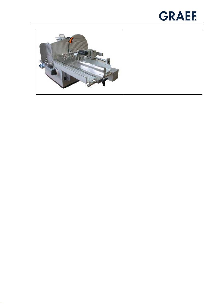
x For rotary current models (400 V), check that
the running direction of the blade is correct.
x The blade must move downwards in direction
of the carriage as shown in the illustration.
x If the running direction is incorrect, use a
screwdriver to turn the phase change in the
network adapter plug by 180°.
x Moisture: Degree of protection IP 33! High humidity or condensation can damage the
machine.
x Lay and connect the power supply cord so that no-one can fall or trip over it.
x The machine is designed for use in sales rooms.
1.1.2. Proper Use
The fully automatic slicers VA 802/804/806 are designed
to slice only the following types of food:
Sausage / meat / ham / slicing cheese
Do not attempt to slice frozen foods.
Do not attempt to slice vegetables or food that has bones.
Remove any metal braces on the goods to be sliced.
Unauthorised modifications to the machine are prohibited for safety reasons.
The operating, maintenance and service instructions
described in this instruction manual must be strictly observed.
1.1.3. Natural Wear
Natural wear is not covered by our warranty or liability.
7
General Information
1.1.4. Potential Sources of Danger
Caution!
Danger of injury!
Never reach into the area of the moving carriage.
Caution!
Danger of injury!
The blade is sharp and can sever body parts.
Your fingers, and especially your thumb, are at risk. For this reason, never reach into the
space between the last slice clamp and the blade or the limit stop if the limit stop plate is
not completely closed. When the machine is not in use, the stop plate must always be set
to the zero position.
Caution!
Injury through electric shock.
The machine operates with a mains voltage of 230 V or 400 V and must therefore not be
opened. The protective earth conductor system must be connected in any case, otherwise
there is a risk of severe electric shocks.
Caution!
Hazards posed by the chain frame.
Never put your hands near the chain frame during operation. The spikes can cause
serious injury.
The placing arm that removes the sliced food moves very quickly and can injure hands or
other parts of the body in case of contact.
Caution!
Risk of injury.
In the area of the food holder, there is a risk of injury posed by the spikes and the food
holder suddenly dropping when inserting the product.
Caution!
Risk of injury.
When mounting parts which can be removed for cleaning.
8

General Information
1.1.5. Workplace
Only operate the machine if you are standing in a secure position.
Stand in front of the machine so that the power on/off button is facing you.
Keep your workplace clean at all times.
The machine must be positioned on a solid, even and stable base that can support the
weight of the machine and the dynamic forces of the moving parts.
1.1.6. Authorised Users
The machine may only be operated by people who:
Have read and understood the operating instructions
Have been instructed thoroughly by the operator
Have been instructed on the dangers of the machine and the hygiene regulations
The machine may only be serviced and repaired by specialists.
Take precautions to prevent unauthorised persons from using, cleaning or servicing the
machine.
1.1.7. Protective Clothing and Equipment
Wear close-fitting clothes when operating the machine. Please also observe the hygiene
regulations.
When executing cleaning or maintenance work in the area of the knife, be sure to wear
cut-resistant gloves with pulse protection.
When transporting the machine, be sure to always wear steel-toe boots.
9
Operation
2. Description
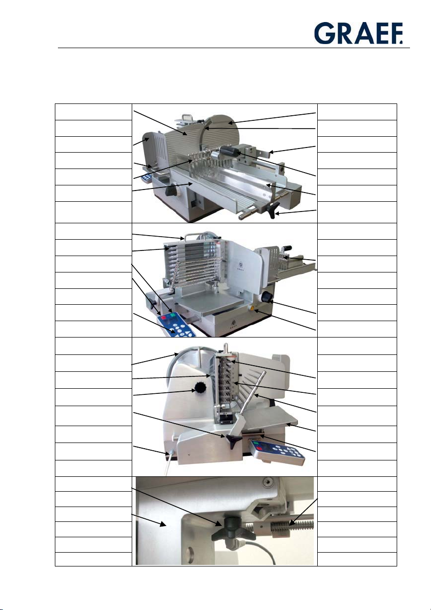
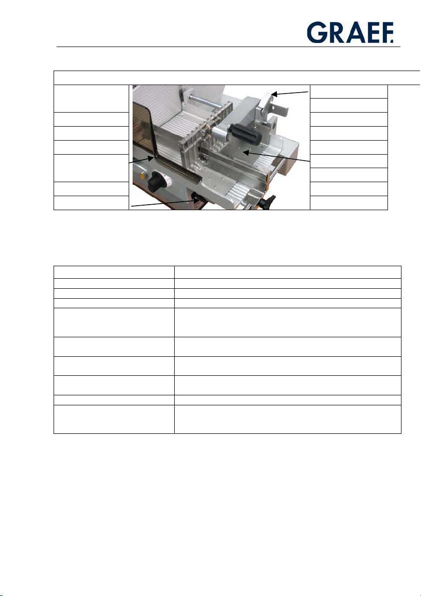
2.1. Designation of the Machine Parts
Stop plate Blade cover plate
Blade
Thumb/finger guard Return lever
Carriage handle
Last slice clamp Last slice clamp handle
Carriage Guide rail
Locking screw
Chain frame handle
Chains
On button
Off button
Operator Slice thickness control
Last slice clamp
Start-stop button
Blade guard ring
Scraper Pressing roller
Thumb wheel Scraper comb
Placing arm star grip
Tray
Power cable Tray guide
Carriage star grip
Feeder shaft
Bearing block
Placing arm
(removable beater)
10
Operation
Special Features VA 802
Lock (VA 802H)
Thumb guard
with hand support
T-handle (VA 802H)
Feed carriage
2.2.Protective Devices
Device Function
Off button Switches the machine off immediately
Blade guard ring Prevents accidental contact with the blade
Limit stop lock Locks the limit stop when the carriage has been tipped off the machine
Carriage drive starting lockout Prevents the carriage and blade drive from switching on when the
Thumb/finger guard Prevents accidental contact with the blade
Chain frame cover Prevents access to the back or catching in the chain tips running to the
Undervoltage mechanism Prevents the machine from starting up again after an interruption to the
Blade sharpener with guard cover Prevents accidental contact with the blade
Sharpening mode Prevents the carriage drive from being switched on during the
slicing thickness is below “Zero“ or the carriage has been tipped off
(cleaning mode)
blade
power supply, such as a “power cut”
sharpening process. The blade drive can only be switched on and off
using the on and off buttons.
11
Operation
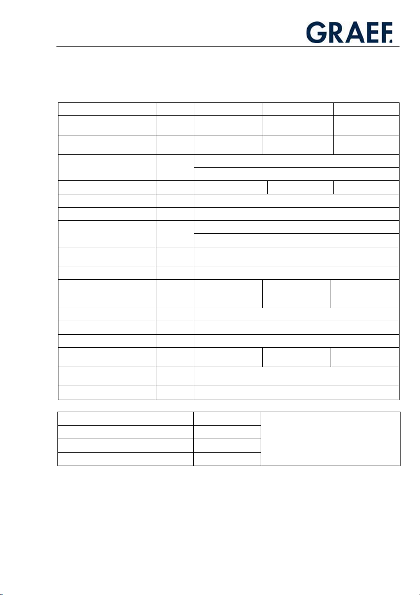
2.3.Technical Dimensions
VA 802 VA 804 VA 806
Dimensions L x W x H 600 x 880 x 500 mm 600 x 1060 x 500 mm 600 x 1240 x 500
Workspace L x W x H 700 x 920 x 640 mm 700 x 1100 x 640 mm 700 x 1280 x 640
Minimum: 480 x 440 mmSpace occupied L x W
Ideal: 540 x 440 mm
Weight W Approx. 68 kg Approx. 70 kg Approx. 72 kg
Blade diameter D 300 mm
Blade speed N 229 rpm
Max. 250 x 180 mmDimensions with chain frame L x H
Min. 30 x 30 mm
Dimensions without chain
frame
Slicing length L 250 mm
Largest distance between last
slice clamp and blade
(clamping distance)
Tray size L x W 300 x 255
Length of tray run s 160 mm
Slice thickness T 0.5 - 10 mm
Slicing speed maximum V Max. 70 strokes per
Emissions – noise level acc. to
EN ISO 11204, at idling
Vibration total value < 2,5m/s² (for VA 802H)
L x H Max. 260 x 195 mm
L 230 mm 420 mm 600 mm
Leq < 69 dB (A)
minute
Max. 60 strokes per
minute
mm
mm
Max. 55 strokes per
minute
Power consumption P1 [W]
Frequency f [Hz]
Current I [A]
Voltage UN [V]
See type plate
12

Operation
2.4. Basic Machines Equipment
The models VA 802, VA 804 and VA 806 of the automatic slicing machine series VA 800
differ in size and have some different carriage characteristics.
All models share the same basic features:
General information
x Smooth, accessible high quality anodized surfaces
x Baking finished lower part
x Hard- chrome plated 300 mm blade with a narrow blade guard for ideal
slicing results
x Locked blade cover plate
x Carriage with motorized feeding of food to be sliced
x Carriage stroke rate that can be adjusted without levels
x Slicing parameters as listed in the “Technical Dimensions“ table
x Control panel that is clearly laid out and easy to reach, and has a membrane
keypad that is proof against dripping water
Standard placing programmes
x Stacking: up to 4 stacks
x Long fanning: up to 4 rows
x Cross fanning: up to 4 rows
x Circular placing
Variable starting programme
x It is possible to determine which programme is to appear after switching on,
and to store this information by pressing a button.
Carriage size differences:
x VA 802 o Carriage with 230 mm clamping distance
x VA 804 o Carriage with 420 mm clamping distance
x VA 806 o Carriage with 600 mm clamping distance
13

Operation
2.5. Options
Important!You can order the following options in addition to the basic
equipment of the slicing machine when you place your order. This means that none
of the following equipment is part of models VA 802, VA 804 or VA 806. Please
check your order documentation to see which of these options are part of your
!
machine.
2.5.1. Semi-automatic Function
(model VA 802 only)
x Switching to “semi-automatic“ mode with servo-drive assisted carriage for easy
manual carriage movement
2.5.2. Additional Menu Standard Functions
(for all models)
x Automatic calibre recognition
- Automatic cross section recognition of the food to be sliced
- Automatic adjustment of the carriage run to the cross section of the product
- Automatic adjustment of placing distances for optimum use of the selected
placing pattern
x Placing format
- Entering of the placing pattern L x B for adapting to the selected packaging
(tray, film and so on)
x Counting mode
- Specification of the number of portions
- Specification of breaks during which the food to be sliced is taken off the tray in
continuous mode
- Specification of continuous mode as a standard function
2.5.3. PLU Programming
(for all models)
x Storing up to 100 PLU with the following parameters:
- Placing type (stacking, fanning, ...)
- Number of stacks, rows
- Number of slices
- Number of portions
- Initial position of the placing pattern
- Distance between stacks, rows
14
Operation
3. Operation
3.1. Operating Controls
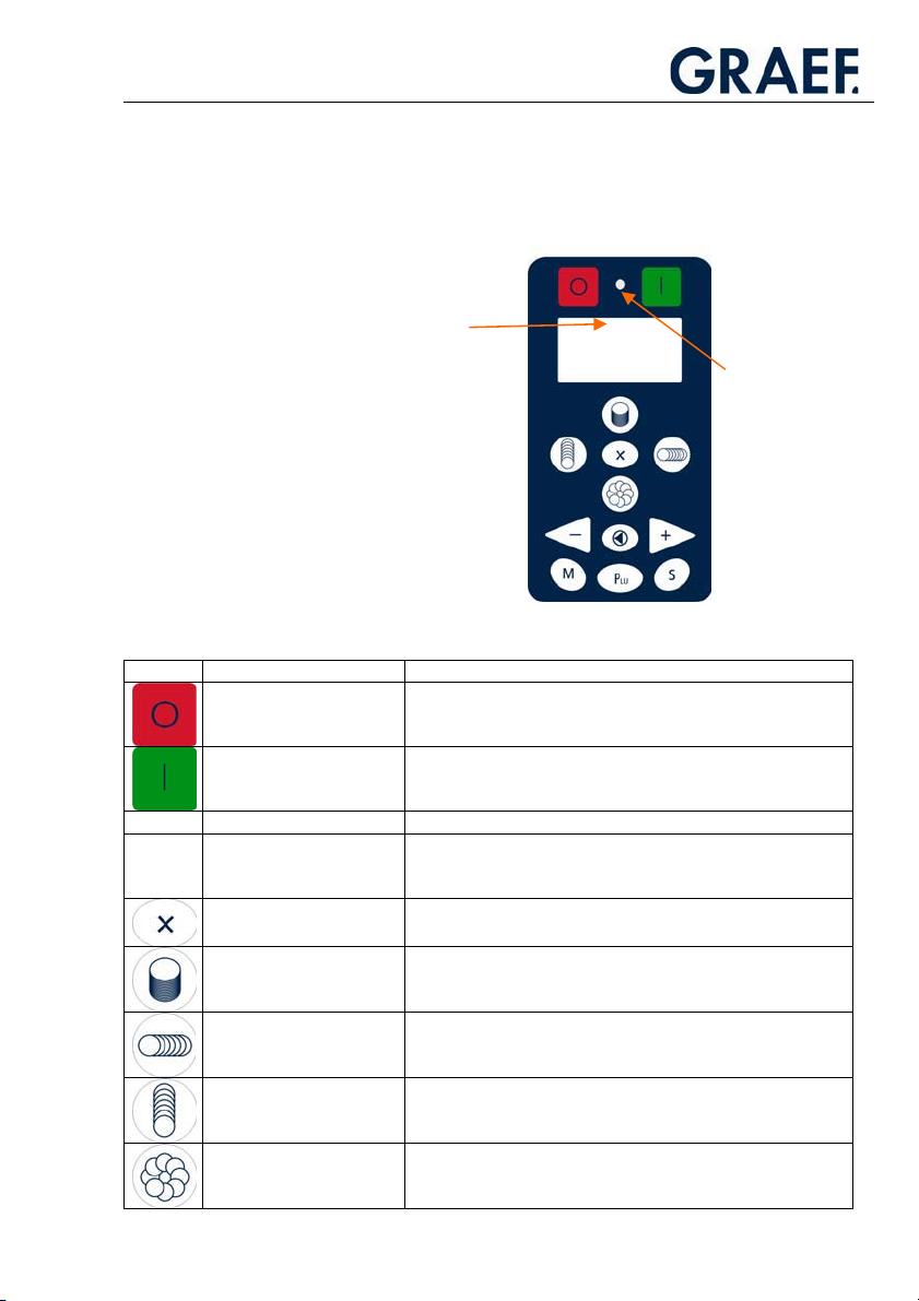
3.1.1. Operating Terminal
Display
(graphical display)
Signal lamp
Symbol Designation Function
Main “OFF“ switch
Main “ON” switch
Signal lamp
Graphical display
(only display!)
X button
Stacking button
Cross shingling button
Long shingling button
Circular shingling button
x Switches off the machine
x Switches on the machine. The machine is ready for slicing.
x Shows that the machine is ready for operation
x Indicates number of slices, cutting programme, PLU, slice
thickness, menu programme (PLU programming, maintenance
intervals etc.)
x Generates 2, 3 or 4 stacks or rows
x Selects the stacking stack function
x Stores the set data (tray dimension, number of slices, cutting
mode, ...) when pressed until a beep is emitted
x Selects the cross fanning function
x Stores the set data (tray dimension, number of slices, cutting
mode, ...) when pressed until a beep is emitted
x Selects the long fanning function (press 1x briefly)
x Stores the set data (number of slices, slicing mode, ...) when
pressed until a beep is emitted
x Selects the circular fanning function
x Stores the set data (number of slices, slicing mode, ...) when
pressed until a beep is emitted
15
Operation
Minus button
Reset button
Plus button
Menu button
PLU button
Carriage stroke button
Button combination M +
PLU
+
x Reduces the edited value
x Moves UP in the selection menu
x Reduces the carriage strokes during operation
x Cancels the active cutting programme
x Resets to zero
x Moves up within the menu hierarchy
x Confirms an entry
x Increases an edited value
x Moves down in the selection menu
x Increases the carriage strokes during operation
x Activates sub-programmes (customer service)
x Switches on PLU mode, the plus/minus buttons can then be
used to select the PLUs
x On pressing this button, the carriage speed (lifting speed) can
be controlled using the plus/minus buttons.
x Programmes PLUs (new/change/delete)
x Changes the standard placing programme (PLU 0000)
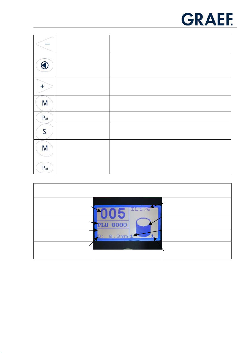
Explanation of the values and symbols in the display
Slice count Portion specifications in continuous
PLU
(0000= Standard programme)
T: Set value slicing thickness
(Display only in PLU mode)
D: Current slicing thickness Number of stacks/rows placed in
(can be set using the “X“ button)
mode “EL”
(No display in normal mode)
Placing function
(stacking, fanning, ...)
Current value of the stack/row
one layer
16
Operation
Other Operating Controls
x Sets the slice thickness
Slice thickness regulator
Last slice clamp
Return lever
Yellow Start-Stop button
x Sets the limit stop lock
x Sets the sharpening mode
x Clamps and feeds the food to be sliced to the blade
x Releases the last slice clamp from the feeder shaft so
that it can be moved freely, e.g. when new food is
being clamped
x Starts the cutting process
x Stops the cutting process
3.2. Programmes
You can either work in the standard mode or access specially defined placing
programmes through PLU. The standard mode makes it possible to combine basic
functions such as stacking, long-shingling, cross-shingling or circular shingling with the
following parameters: number of slices, stroke speed and number rows/stacks.
3.2.1. Slicing in the Standard Mode (PLU=0000)
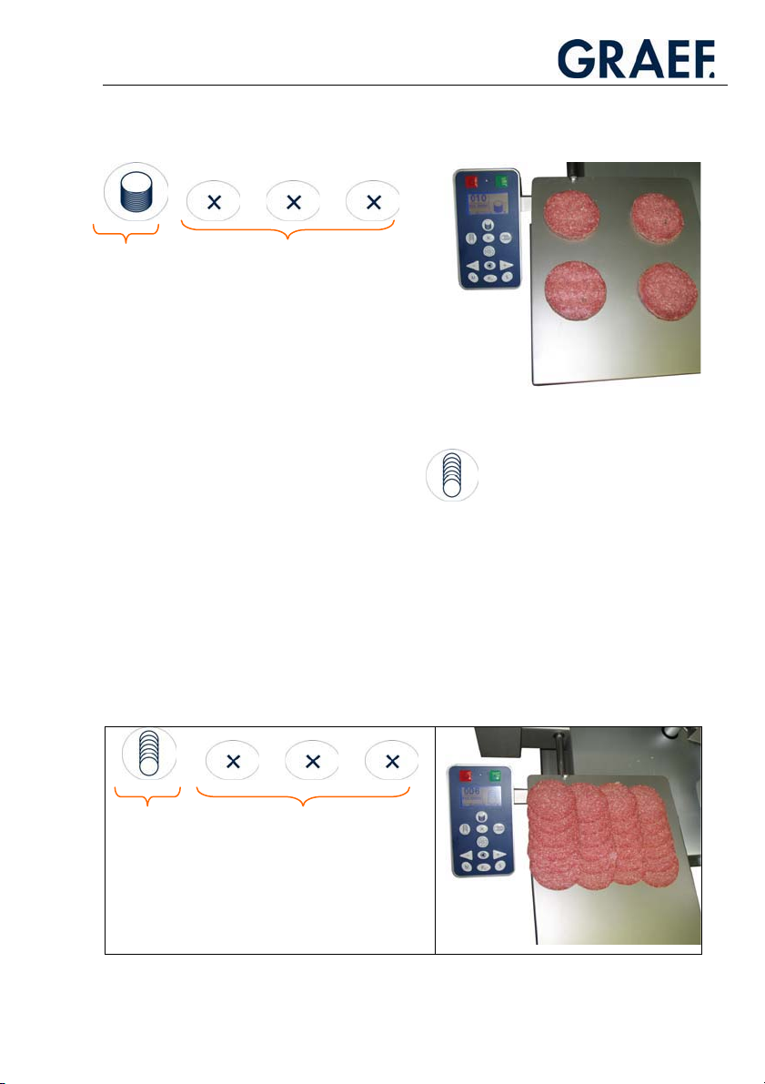
3.2.1.1. Stackinging
The stacking function enables stack heights of up to 60 mm.
This function is selected by simply pressing the stack button. The display shows the
symbol for stacking. You can preset the number of slices using the plus/minus buttons.
If multiple stacks are desired, you can increase the number of stacks with the “X“ button.
Up to 4 stacks are possible.
When making preparations, it is recommended to set the slice counter to “000”.
In this way, the maximum stack height is always achieved.
If stacks are to be generated on portioning units (foils, PE trays, foam trays, trays etc.),
you can enter the outer dimensions of the portioning units L x W for central placing.
(Option: the machine then uses the calibre recognition option to calculate the best
placing point).
17
Example:
Operation
+ + +
Select function
“Stacking”
=
+ 3 x “X button”
= 4 stacks
3.2.1.2. Long shingling
The long fanning function is for placing the individual slices in rows parallel to the stop.
The number of rows can be set using the “X“ button. Up to 4 rows are possible with the
standard programme. When making preparations, it is recommended to set the slice
counter to “000”. The machine then fans multiple layers on top of each other.
If rows are to be generated on portioning units (foils, PE trays, foam trays, trays etc.), you
can enter the outer dimensions of the portioning units L x W for central placing. (Option:
the machine then uses the calibre recognition option to calculate the best placing point).
Example:
+ + +
=
Select function
“Long shingling”
+ 3 x “X button”
= 4 rows
18
 Loading...