

Page 1
Technical changes reserved.
GRAEF (d) February 2010 -CB
OPERATING MANUAL (original)
Semi-Automatic
Slicing Machine
HA 800 HA 810
Machine No. :
Year of construction :
Page 2

2
1 General Information ........................................................................................................5
1.1 Safety – Notes on the Warranty................................................................................5
1.1.1 Set-up and Instruction.....................................................................................5
1.1.2 Proper Use ......................................................................................................7
1.1.3 Natural Wear...................................................................................................8
1.1.4 Potential Sources of Danger............................................................................8
1.1.5 Workplace.......................................................................................................9
1.1.6 Authorised Users.............................................................................................9
1.1.7 Protective Clothing and Equipment.................................................................9
2 Description.....................................................................................................................10
2.1 Designation of the Machine Parts ...........................................................................10
2.2 Protective Devices...................................................................................................11
2.3 Technical data.........................................................................................................12
2.4 Basic Machine Equipment.......................................................................................13
2.5 Options ...................................................................................................................14
2.5.1 Additional Menu Standard Functions............................................................14
2.5.2 PLU Programming .........................................................................................14
3 Operation.......................................................................................................................15
3.1 Operating Controls..................................................................................................15
3.1.1 Operating Console ........................................................................................15
3.2 Programs.................................................................................................................17
3.2.1 Slicing in the Standard Mode (PLU 0000)......................................................17
3.2.2 Offset Function (Machines without Calibration Recognition)........................20
3.3 Using the Paper Clamp ...........................................................................................21
3.4 Slicing .....................................................................................................................21
3.5 HA 810 with Vario-Slice Carriage............................................................................23
3.5.1 Tilting the Carriage to the V Position ............................................................24
3.5.2 Tilting the Carriage to the Normal Position...................................................24
3.5.3 Cutting with the VS Carriage ........................................................................25
3.6 The Start Program ...................................................................................................25
3.7 Changing the Standard Program (PLU=0000).........................................................27
3.7.1 The “M+PLU” Additional Menu ...................................................................27
3.7.2 The “M” Additional Menu (OPTION HA 800) ...............................................30
3.7.3 Slicing in the PLU Mode ................................................................................34
3.7.4 Programming a PLU ......................................................................................35
4 Cleaning ........................................................................................................................40
4.1 Preparing for Cleaning ............................................................................................40
4.1.1 Disassembly of the Removable Parts.............................................................41
4.2 Cleaning the Different Parts of the Machine ...........................................................43
4.2.1 Blade and Blade Ring....................................................................................43
4.2.2 Carriage ........................................................................................................44
4.2.3 Chain Frame..................................................................................................45
4.3 Cleaning Schedule...................................................................................................47
Page 3

3
4.3.1 Cleaning Procedure.......................................................................................48
4.4 Assembly.................................................................................................................49
5 Maintenance..................................................................................................................51
5.1 Sharpening the Blade..............................................................................................51
5.1.1 Description of the Blade Sharpener...............................................................51
5.1.2 Preparing the Machine..................................................................................52
5.1.3 Sharpening the Blade....................................................................................52
5.2 Changing the Blade.................................................................................................54
5.3 Lubricating ..............................................................................................................55
6 Faults and Operating Errors ...........................................................................................56
7 Service ...........................................................................................................................57
Page 4

EC DECLARATION OF
CONFORMITY
GEBR. GRAEF GMBH + CO. KG, DONNERFELD 6, D- 59757 ARNSBERG
4
We herewith declare that the design of the following machine
Slicing Machine
Types
HA 800, HA 810
In the design supplied by us complies with the provisions of the following EC
directives:
EC Machine Directive 2006/42/EG
EC EMC Directive 2004/108/EG
EC Low Voltage Directive 2006/89/EG
The following harmonized standards and technical specifications have been
applied:
EN 1974
EN 61000-6-2
EN 61000-6-3
EN 61000-4-[2,3,4,5,6,11]
EN 61000-3-2
EN 55022
Name of the authorized representative: Reinhard Graef
Address of the authorized representative: see manufacture’s address
Changes to the machine not authorized by GRAEF invalidate the present
declaration.
Arnsberg, 11 December 2009 Hermann Graef
- Managing Director -
Page 5

General Information
5
1 General Information
1.1 Safety – Notes on the Warranty
The semi-automatic models HA 800 and HA 810 are equipped with safety devices. They
have been tested for safety.
Nevertheless, hazards cannot be entirely excluded if the machine is used improperly or
not as intended.
These hazards may endanger:
• The health of the user
• The machine and other property of the operator
All persons charged with installing, operating, servicing and repairing the machine must
• Be trained/instructed for the task
• Follow these operating instructions to the letter.
1.1.1 Set-up and Instruction
Store and transport machines in their original packaging until they are set up.
The GRAEF dealer is responsible for set-up and start-up as well as for providing
instructions on how to operate, clean and service the machine.
Customer installation and start-up, incorrect operation, modifications
and removal of the safety equipment are excluded from our area of liability.
Important!
The installation and instruction must be confirmed by your authorised
GRAEF dealer.
The slicing machines weigh approx. 56 kg.
Two adults are required to lift and carry the machine.
The centre of gravity is in the rear third of the machine, where the motor is located.
Always lift and carry the machine by the machine housing.
x For longer company-internal transport routes:
use a suitable handcart.
x Take off removable parts such as chain frame, tray and beater before transport.
!
Page 6

General Information
6
x Secure the carriage by inserting paper or cardboard between the thumb guard and
the stop plate.
x Set the slicing thickness below “0” by turning the slicing thickness control to the limit
position.
1.1.1.1 Set-up site requirements
The base must fulfil the following requirements:
x It must be sufficiently stable, strong, level, flat and non-slip.
x It must be of sufficient height to allow slicing while standing.
x It must meet the space requirements listed in “Workspace” (see Technical Data).
x It must be located away from busy corridors.
x It must not be close to any doors.
x It may not be in the swinging area of a door, nor in the entrance area of a door.
x When using Nirosta tables, Resopal supports or similar materials: Ensure that there is
no oil or grease on the surface.
x Ensure sufficient lighting of at least 300 lux
1.1.1.2 Unpacking the machine
Caution!
The machine may only be unpacked and set up by authorised customer service / sales
personnel. Check the required working space (with the machine switched off!):
• Hold the last slice clamp by the handle
• Lift up the last slice clamp
• Move the carriage all the way forward and back
If the carriage or last slice clamp comes into contact with other objects, you must provide
a larger work space.
!
Page 7
General Information
7
1.1.1.3 Electrical connection
x Check if the local supply voltage conforms to the specifications indicated on the
rating plate. If it does not, you may not connect the machine.
x The electrical socket must comply with the VDE (Association of German Electricians)
regulations.
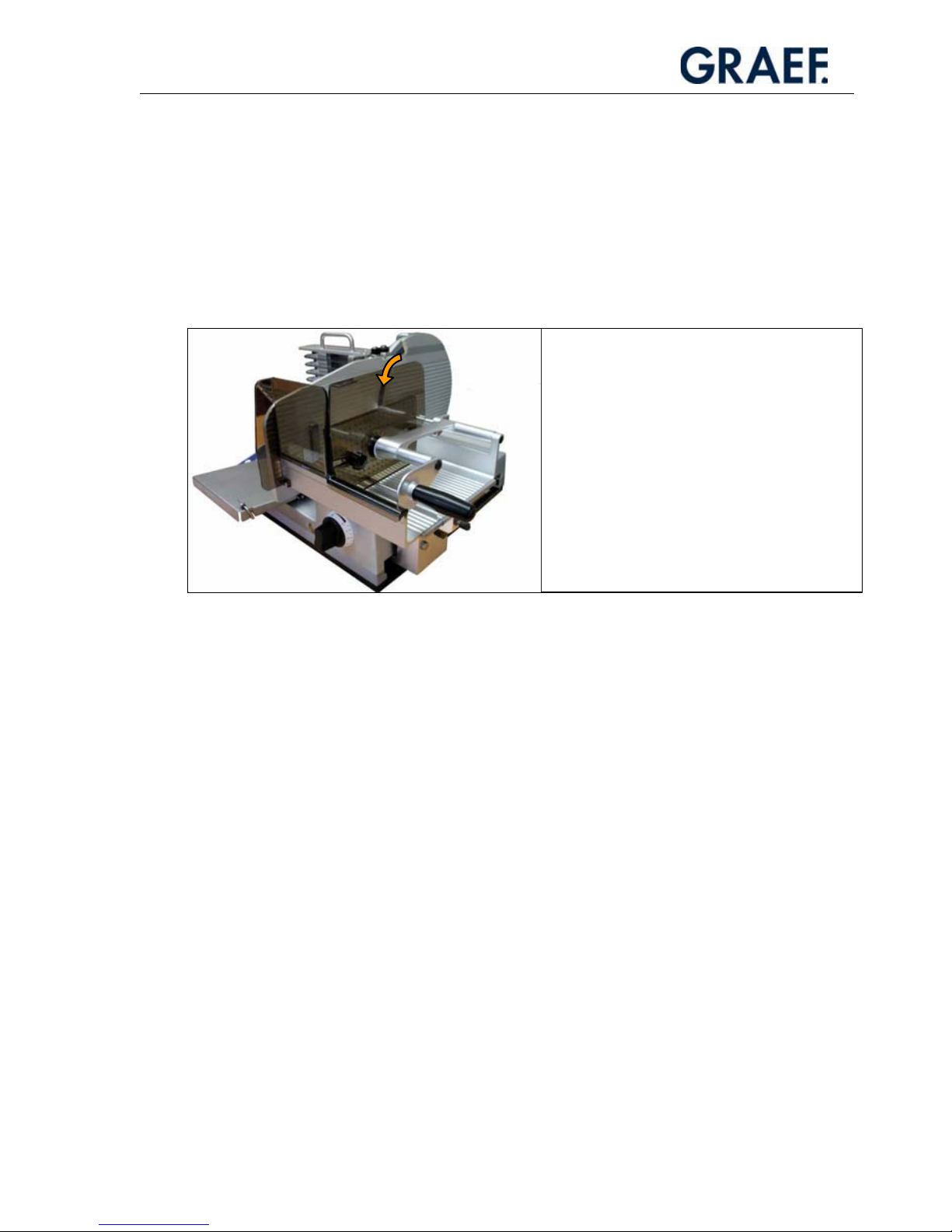
x For rotary current models (400 V), check that
the running direction of the blade is correct.
x The blade must move downwards in direction
of the carriage as shown in the illustration.
x If the running direction is incorrect, use a
screwdriver to turn the phase change in the
network adapter plug by 180°.
x Moisture: Degree of protection IP 33! High humidity or condensation can damage the
machine.
x Lay and connect the power supply cord so that no-one can fall or trip over it.
x The machine is designed for use in sales rooms.
1.1.2 Proper Use
The HA 800 / HA 810 semi-automatic slicers are exclusively intended
for slicing only the following types of food:
sausage / meat / ham / cheese.
Do not attempt to slice frozen foods.
Do not attempt to slice vegetables or food with bones.
Remove any metal braces on the goods to be sliced.
Unauthorised modifications to the machine are prohibited for safety reasons.
The operating, maintenance and service instructions described in this instruction manual
must be strictly observed.
Page 8

General Information
8
1.1.3 Natural Wear
Natural wear is not covered by our warranty or liability.
1.1.4 Potential Sources of Danger
Caution!
Danger of injury!
Never reach into the area of the moving carriage.
Caution!
Danger of injury!
The blade is sharp and can sever body parts.
Your fingers, and especially your thumb, are at risk. For this reason, never reach into the
space between the last slice clamp and the blade or the limit stop if the limit stop plate is
not completely closed. When the machine is not in use, the stop plate must always be set
to the zero position.
Caution!
Injury through electric shock.
The machine operates with a mains voltage of 230 V or 400 V and must therefore not be
opened. The protective earth conductor system must be connected in any case, otherwise
there is a risk of severe electric shocks.
Caution!
Hazards posed by the chain frame.
Never put your hands near the chain frame during operation. The spikes can cause
serious injury.
The placing arm that removes the sliced food moves very quickly and can injure hands or
other parts of the body in case of contact.
Page 9

General Information
9
Caution!
Risk of injury.
In the area of the food holder, there is a risk of injury posed by the spikes an the food
holder suddenly dropping when inserting the product.
Caution!
Risk of injury.
When mounting parts which can be removed for cleaning.
1.1.5 Workplace
Only operate the machine if you are in a standing in a secure position.
Stand in front of the machine so that the power ON/OFF button is facing you.
Keep your workplace clean at all times.
The machine must be positioned on a solid, even and stable base that can support the
weight of the machine and the dynamic forces of the moving parts.
1.1.6 Authorised Users
The machine may only be operated by people
who have read and understood the operating instructions
who have been instructed thoroughly by the operator
who have been instructed on the dangers of the machine and the hygiene regulations.
The machine may only be serviced and repaired by authorised specialists.
Take precautions to prevent unauthorised persons from using, cleaning or servicing the
machine.
1.1.7 Protective Clothing and Equipment
Wear close-fitting clothes when operating the machine. Please also observe the hygiene
regulations. When executing cleaning or maintenance work in the area of the knife,
be sure to wear cut-resistant gloves with pulse protection.
When transporting the machine, be sure to always wear steel-toe-boots.
Page 10
Description
10
2 Description
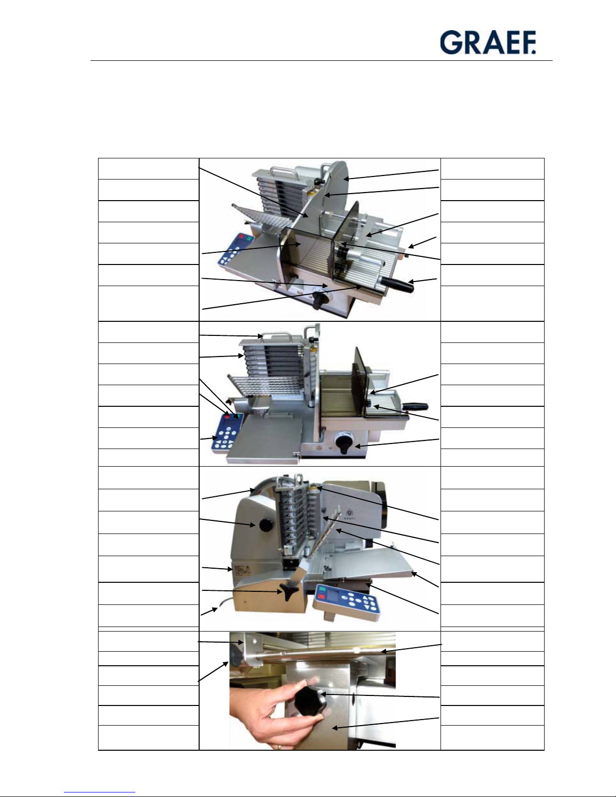
2.1 Designation of the Machine Parts
Stop plate
Blade cover plate
Blade
Last slice clamp
Guide rail
Thumb/finger guard Pusher guard
Carriage Last slice clamp handle
Carriage handle
Chain frame handle
Chains
On button Last slice clamp plate
Off button
Knurled nut
Operating console Slice thickness control
Blade guard ring
Thumb wheel Pressing roller
Scraper comb
Type plate
Placing arm
(removable beater)
Placing arm star grip Tray
Power cable Tray guide
Guide rail
Slicing guide rail
Locking screw
Bearing block star grip
Bearing block
Page 11
Description
11
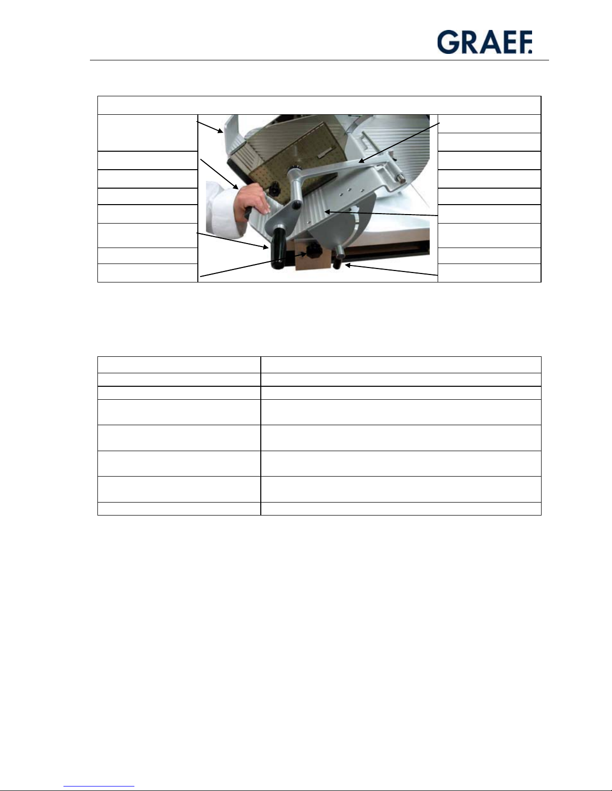
HA 810 Special Features
Last slice clamp
Thumb guard
Hand rail
Vario-Slice carriage
Last slice clamp
handle
Bearing block star grip Tilting lever
2.2 Protective Devices
Device Function
Off button Switches the machine off immediately.
Blade guard ring Prevents accidental contact with the blade.
Limit stop lock Locks the limit stop when the carriage has been tipped off the
machine.
Thumb/finger guard Prevents accidental contact with the blade.
Chain frame cover Prevents access to the back or catching in the chain tips running to
the blade.
Undervoltage mechanism Prevents the machine from starting up again after an interruption
to the power supply, such as a power cut.
Blade sharpener with guard cover Prevents accidental contact with the blade.
Page 12

Description
12
2.3 Technical data
HA 800 HA 810
Dimensions L x W x H 600 x 840 x 450 mm 600 x 840 x 500
Workspace L x W x H 700 x 900 x 640 mm
Minimum: 480 x 440 mm Space occupied L x W
Ideal: 540 x 440 mm
Weight W approx. 56 kg
Blade diameter D 300 mm
Blade speed N 229 rpm
Max. 250 x 180 mm Dimensions with chain frame L x H
Min. 30 x 30 mm
Dimensions without chain frame L x H Max. 260 x 195 mm
Carriage length L 300 mm
Largest distance between last slice
clamp and blade (clamping
distance)
L 150 mm 155 mm
Tray size L x W 300 x 255
Length of tray run T 160 mm
Slice thickness T 0.5 - 10 mm
Slicing speed maximum V Max. 160 strokes per minute
Noise level acc. To EN ISO 11204,
at idling
Leq < 69 dB (A)
Vibration total value < 2,5 m/s²
Power consumption P1 [W]
Frequency f [Hz]
Current I [A]
Voltage UN [V]
See type plate
Page 13

Description
13
2.4 Basic Machine Equipment
Semi-automatic slicing machine models HA 800 and HA 810 differ in terms of size and
some characteristics of the carriage.
All models share the same basic features:
General
x Smooth, accessible high quality anodized surfaces
x Stove-enamelled finished lower part
x Hard-chrome plated 300 mm blade with a narrow blade guard for ideal
slicing results
x Locked blade cover plate
x Slicing parameters as listed in the “Technical Data” table
x Operating console that is clearly laid out and easy to reach with waterproof
membrane keypad
Standard placing programs
x Stacking: up to 4 stacks
x Long fanning: up to 4 rows
x Cross fanning: up to 4 rows
x Circular placing
Variable starting program
x It is possible to determine which program is to appear after switching on, and
to store this information by pressing a button.
Carriage size differences:
x HA 800 o Carriage with 150 mm clamping distance (advance distance
between blade and endpiece holder)
x HA 810 o Carriage with 155 mm clamping distance (advance distance
between blade and endpiece holder)
Carriage characteristics:
x HA 810: In a tilted position, small cutting material can be sliced without the
guide rail.
Page 14

Description
14
2.5 Options
Important!
You can order the following options in addition to the basic equipment of the
slicing machine when you place your order. This means that none of the following
equipment is part of models HA 800 or HA 810. Please check your order
documentation to see which of these options are part of your machine.
2.5.1 Additional Menu Standard Functions
x Automatic calibre recognition (
only HA 800)
- Automatic cross section recognition of the food to be sliced
- Automatic adaptation of distances for optimum utilisation of the selected placing
pattern
x Placing format (
only HA 800)
- A placing pattern (L x B) can be entered to adjust to the selected packaging (tray,
film and so on)
x Carriage position recognition for Vario-Slice carriage
(HA 810 only)
- Optimum placing of product on the tray
x Counting mode
- Specification of the number of portions
- Specification of breaks during which the food to be sliced is taken off the tray in
continuous mode
- Specification of continuous mode as a standard function
2.5.2 PLU Programming
(Optional for all models)
x Storing up to 100 PLU with the following parameters:
- Placing type (stacking, fanning, ...)
- Number of stacks, rows
- Number of slices
- Number of portions
- Initial position of the placing pattern (cutting material positioning on the tray
surface)
- Distance between stacks, rows
!
Page 15
Operation
15
3 Operation
3.1 Operating Controls
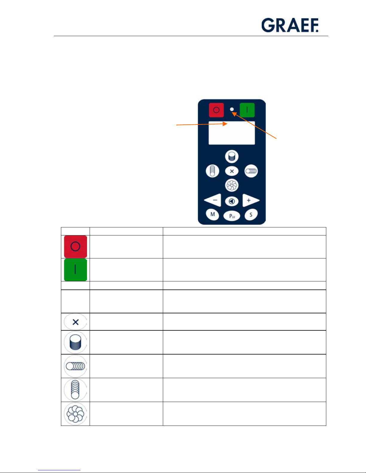
3.1.1 Operating Console
Symbol Designation Function
Main “OFF” switch
x Switches off the machine.
Main “ON” switch
x Switches on the machine. The machine is ready for slicing.
Signal lamp
x Shows that the machine is ready for operation.
Graphical display (only
display!)
x Indicates number of slices, cutting program, PLU, slice
thickness, menu program (PLU programming, maintenance
intervals etc.).
X button
x Generates 2, 3 or 4 stacks or rows.
Stacking button
x Selects the stacking function.
x Stores the set data (tray dimension, number of slices, cutting
mode, ...) when pressed until a beep is emitted.
Cross fanning button
x Selects the cross fanning function.
x Stores the set data (tray dimension, number of slices, cutting
mode, ...) when pressed until a beep is emitted.
Long fanning button
x Selects the long fanning function (press 1x briefly).
x Stores the set data (number of slices, slicing mode, ...) when
pressed until a beep is emitted.
Circular fanning button
x Selects the circular fanning function.
x Stores the set data (number of slices, slicing mode, ...) when
pressed until a beep is emitted.
Display (graphical
display)
Signal lamp
Page 16
Operation
16
Minus button
x Reduces the edited value.
x Moves UP in the selection menu.
x Reduces the carriage strokes during operation.
Reset button
x Cancels the active cutting program.
x Resets to zero.
x Moves up within the menu hierarchy.
x Confirms an entry.
Plus button
x Increases an edited value.
x Moves down in the selection menu.
x Increases the carriage strokes during operation.
Menu button
(
only HA 800)
x Calls subprograms.
PLU button
(
only VA 800)
x Switches on PLU mode, the Plus/Minus buttons can then be
used to select the PLUs.
Carriage stroke button
(
only VA 800)
x On pressing this button, the carriage speed (lifting speed) can
be controlled using the Plus/Minus buttons.
+
Button combination M +
PLU
x Programs PLUs (new/change/delete).
(
only VA 800)
x Changes the standard placing program (PLU 0000).
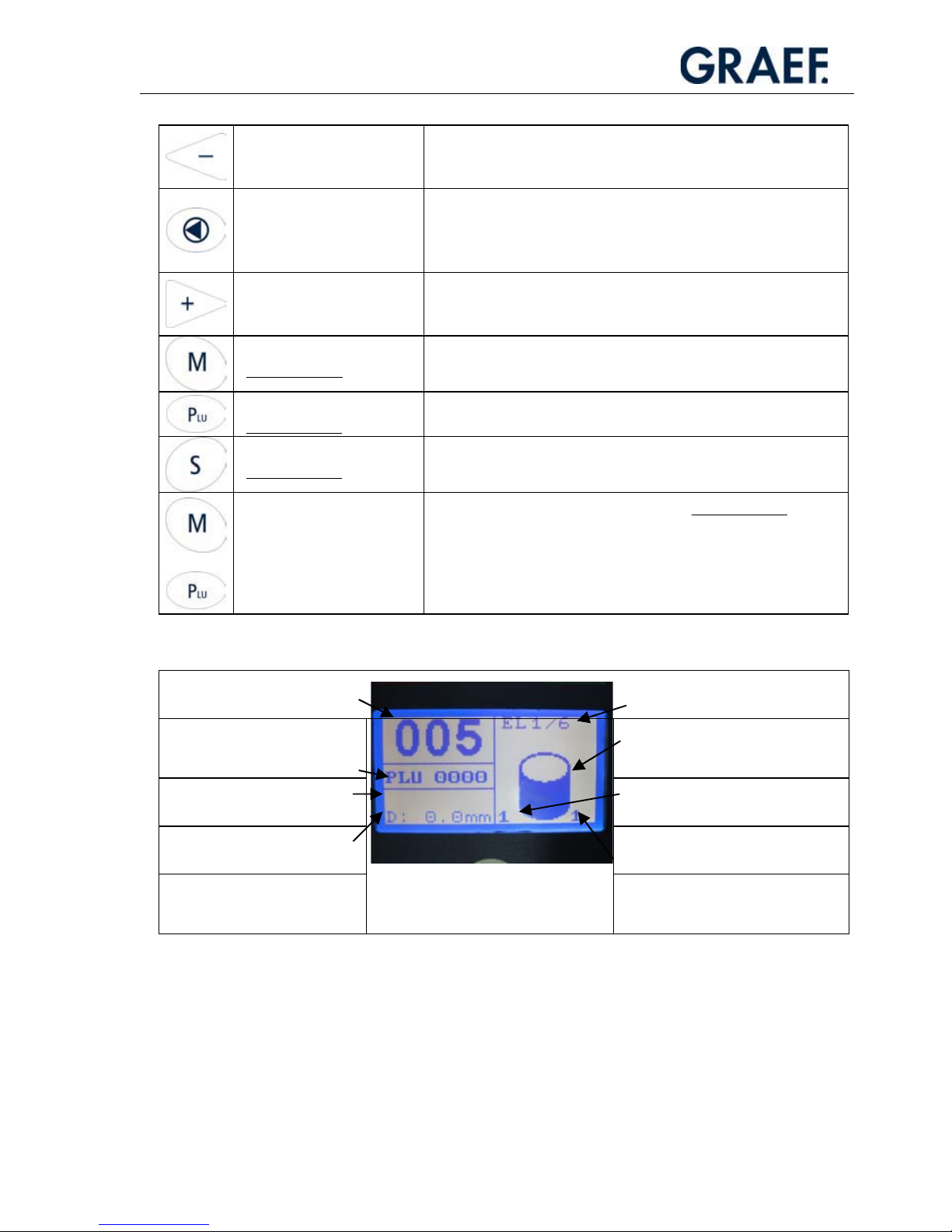
Explanation of the values and symbols in the display
Slice count Portion specifications in
continuous mode “EL”
(No display in normal mode)
PLU
(0000 = Standard program)
Placing function
(stacking, fanning, ...)
S: Set value slicing thickness
(Display only in PLU mode)
Current value of the stack/row
D: Current slicing thickness
Number of stacks/ rows placed in
one layer
(can be set using the “X” button)
Page 17

Operation
17
3.2 Programs
You can either work in the standard mode or access specially defined placing programs
using PLU. The standard mode makes it possible to combine basic functions such as
stacking, long-fanning, cross-fanning or circular fanning with the following parameters:
number of slices and number rows/stacks.
3.2.1 Slicing in the Standard Mode (PLU 0000)
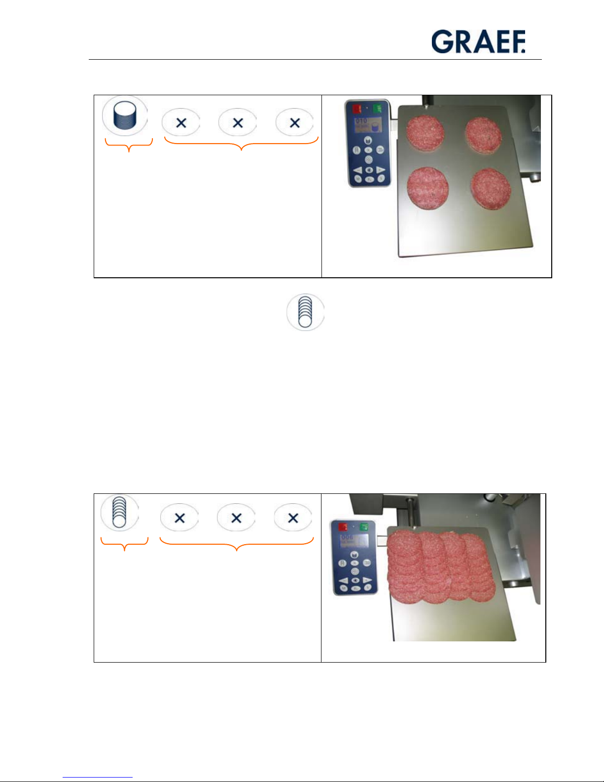
3.2.1.1 Stacking
The stacking function enables stack heights of up to 60 mm.
This function is selected by simply pressing the stack button. The display shows the
symbol for stacking. You can preset the number of slices using the +/- buttons. If multiple
stacks are desired, you can increase the number of stacks with the X button. Up to 4
stacks are possible.
When making preparations, it is recommended to set the slice counter to “000”. In this
way, the maximum stack height is always achieved.
If stacks are to be generated on portioning units (foils, PE trays, foam trays, trays etc.),
you can enter the outer dimensions of the portioning units L x W for central placing.
(Option only HA 800: the machine then uses the calibre recognition option to calculate
the best placing point.)
Other Operating Controls
Slice thickness control
x Sets the slice thickness.
x Sets the limit stop lock (carriage removable)
x Sets the sharpening mode (completely opened)
Last slice clamp
x Clamps and feeds the food to be sliced to the blade.
Guide rail
x Fixes food product on the carriage.
x Calibre scanning
x Optimum use of placing surface
Page 18
Operation
18
Example:
+ + +
=
3.2.1.2 Long Fanning
The long fanning function is for placing the individual slices in rows parallel to the stop.
The number of rows can be set using the “X” button. Up to 4 rows are possible with the
standard program. When making preparations, it is recommended to set the slice counter
to “000”. The machine then fans multiple layers on top of each other.
If rows are to be generated on portioning units (foils, PE trays, foam trays, trays etc.), you
can enter the outer dimensions of the portioning units L x W for central placing. (Option
only HA 800: the machine then uses the calibre recognition option to calculate the best
placing point.)
Example:
+ + +
+ 3 x “X button”
= 4 stacks
Select
“Stacking”
function
=
3 x “X button”
= 4 rows
Select
“Long fanning”
function
Page 19

Operation
19
3.2.1.3 Cross Fanning
The cross fanning function is for placing the individual slices in rows parallel to the chain
frame. The number of rows can be set using the “X” button. Up to 4 rows are possible
with the standard program. When making preparations, it is recommended to set the
slice counter to “000”. The machine then fans multiple layers on top of each other.
If rows are to be generated on portioning units (foils, PE trays, foam trays, trays etc.), you
can enter the outer dimensions of the portioning units L x W for central placing. (Option
only HA 800: The machine then uses the calibre recognition option to calculate the best
placing point.)
Example:
3.2.1.4 Circular Fanning
Circular fanning enables the slices to be placed in a circular pattern.
The diameter of the circle can be altered by adjusting the tray dimensions. In this way,
oval placing patterns are also possible.
Example:
Select
“Cross fanning” function
Select
“Circular fanning” function
Page 20

Operation
20
3.2.2 Offset Function (Machines without Calibration
Recognition)
On machines without calibration recognition, the “Offset function” can be used to
slightly adjust the laying position on the tray, for example, a stack can be placed on the
left, in the centre or on the right of the tray.
Example:
The stacking function has been selected. If
the function button (stacking) is pressed
again, three bars appear in the display.
The plus “+” and minus “-” buttons can be used to
change the position of the highlighted bar and the laying
position of the cutting material is moved on the tray
correspondingly.
OFFSET FUNCTION CHANGE OF LAYING POSITION
Stacking Left, centre, right
Long fanning Left, centre, right
Cross fanning Rear, centre, front
Circular fanning Larger Ø, medium Ø, smaller Ø
Page 21

Operation
21
3.3 Using the Paper Clamp
Press down the lever on the right of the tray to the
back.
Lay the paper (or film) on the tray and push to the
stop limits.
Pull the lever to the front and the paper (or film) is
clamped.
3.4 Slicing
Clean the machine completely, following the cleaning procedures, before you start
slicing.
Preparing the carriage:
x Bring the carriage to the initial position.
x Take hold of the handle of the last slice clamp
and swivel it upwards.
Page 22

Operation
22
x Push the guide rail towards the last slice clamp
as far as required by the food to be sliced.
x Place the sausage to the wall of the carriage
and hold in position with your left hand.
x Using the right hand, pull the guide rail until
about 4 mm before the food product and
tighten the locking screw (mini wing).
x Switch on the machine.
CAUTION!
The carriage is supported by a servo-drive as soon
as you push it towards the blade.
Page 23

Operation
23
x Use the slicing thickness control to set the
slicing thickness.
The value shown in the display is the slice thickness
in mm.
x Select the placing program and specify the
number of slices with the +/- buttons if
necessary.
x Take hold of the handle of the last slice clamp
and swivel it to the “down” position.
x Push the food to be sliced against the rail and
push the carriage towards the blade.
If the food to be sliced is smaller than 150 mm, use
the last slice clamp.
3.5 HA 810 with Vario-Slice Carriage
The Vario-Slice carriage allows you to slice round products, especially narrow ones, in a
tilted position without a guide rail. The procedure for slicing corresponds to that with the
standard carriage.
Page 24

Operation
24
3.5.1 Tilting the Carriage to the V Position
x Press the Off button to switch off the machine.
x Hold the carriage with your left hand by the
black handle.
x Swievel the rocker arm on the right towards you
so that the carriage unlatches.
x Using your left hand, tilt the carriage to the V
position until you hear the carriage latch in. Let
go of the lever while you tilt the carriage.
x You can now slice the product in the same way
as in the normal position.
CAUTION!
The carriage is supported by a servo-drive as soon
as you push it towards the blade.
IMPORTANT!
In the tilted position, the laying position on the tray is different to what it is in the
normal position.
3.5.2 Tilting the Carriage to the Normal Position
x Press the Off button to switch off the machine.
x Hold the carriage with your left hand by the
black handle and hold the carriage steady
before you unlatch the rocker arm.
x Swivel the rocker arm on the right towards
you so that the carriage unlatches.
x Caution! Do not allow the carriage to drop
down.
!
Page 25

Operation
25
x Using your left hand, tilt the carriage to the V
position until you hear the carriage latch in.
Let go of the lever while you tilt the carriage.
3.5.3 Cutting with the VS Carriage
x Swivel up the last slice clamp.
x Insert the product to be sliced.
x Lower the last slice clamp.
x If the food to be sliced is long, place the last slice clamp on the food. If the food is
short (shorter than 155 mm), place the last slice clamp behind the food.
x Switch on the machine.
x Pull the carriage towards yourself if the display has not yet been enabled, i.e. you can
only see the GRAEF logo.
x Select the program.
x Open the stop with the slicing thickness control (the slice thickness can be read off at
the display).
x Slicing now proceeds like on a manual machine; in other words, press the food gently
against the stop and push the carriage towards the blade.
x CAUTION!
The carriage is supported by a servo-drive as soon as you push it towards the blade.
3.6 The Start Program
The start program determines which placing function the machine will display when it is
switched on. You should select the program setting that is most commonly used.
All values that can be changed using the function buttons described above – number
of slices, function, – can be saved by pressing the corresponding function key for
2-3 seconds until the beep sounds. The last stored function is called again when the
machine is switched on again.
Page 26

Operation
26
Example:
START Program P1 P2 P3
Select function
Stacking
Circular
fanning
Long
fanning
Number of slices
10
10 8
Number of
rows/stacks
2
1 3
Press for 2-3
seconds
If programming is done in the sequence P1oP2oP3, the following happens after
switching on the machine:
“Long fanning” function, 3 rows of 8 slices, which is program “P3”.
On changing functions, i.e. by pressing a different button, e.g. Stack, the placing pattern
is set for the corresponding function.
The example above would result in the following stacking pattern: 2 stacks of 10 slices.
It is possible to save the various parameters of a function individually by pressing the
corresponding function button for a long time. However, as already mentioned, the most
recently saved program is always the START program.
Page 27

Operation
27
3.7 Changing the Standard Program (PLU=0000)
In addition to simple variants, like changing the
x Slice count
x Number of stacks/rows (1-4)
x Carriage stroke speed (slices per minute, only for fully automatic machines)
it is possible to adjust the following parameters
x Positions on the tray
x Placing format (option)
x Calibre mode (option)
x Counting mode (option)
in additional menus.
3.7.1 The “M+PLU” Additional Menu
Access the program menu by pressing buttons M+PLU. Here, in the “STANDARD” menu
item, you can change the basic functions relating to fanning distances and positioning on
the tray. Select “Reset” to return all functions to the default settings at any time.
IMPORTANT!
Always press and hold the “M” button and then press the “PLU” button in addition.
!
Navigation in the M+PLU
Page 28

Operation
28
y
x
DELTA Y
Y
0
Parameter Description Possible settings / Remarks
Stacking, ¦ shingling, — shingling
Dist trans
(Delta X)
Crosswise distance: distance
to the next stack in X
Stacking
Dist row Row distance: distance to the
next row
Long fanning
Dist slice Slice distance: distance to the
next slice
Cross fanning
X
Y
Y start
X start
Cross shingling
Stacking ¦ shingling — shingling
Dist cross
Dist length
X
start
Y start
Max.
height
o shingling General
Reset
Standard
Dist slice
Dist row
X
start
Y start
Slices/row
X start
Y
start
Dia circle
Slices/row
Round
Dist row
Dist slice
X
start
Y start
Slices/row
Standard
+
Page 29

Operation
29
Dist length Lengthways distance: distance
to the next slice in Y
Stacking
Dist slice Slice distance: distance to the
next slice
Long fanning
Dist row Row distance: distance to the
next row
Cross fanning
X start Moves the initial placing point
in X-direction
Stacking, long fanning, cross fanning
Y start Moves the initial placing point
in Y-direction
Stacking, long fanning, cross fanning
Max.
height
Maximum stacking height Only in stacking mode
Slices Slices per row or fan Not in stacking mode
Special circular fanning features
Diameter of the circle through
the central points of the slices
(partial diameter)
Note:
The outer diameter of the
“DA” circular fan is the result
of the cutting material calibre
DK + Dm
Example:
Salami DK = Ø 60
Set semi-circle Dm = 100
DK 60
Dm + 100
Dm
DA = 160
X start
(X0)
Smallest distance of the y axis
to the slice circle = start
position in X
Y start
(Y0)
Smallest distance of the x axis
to the slice circle = start
position in Y
Round Select option “0”
or “1” “0=oval or circle”
or “1= circle”
In option “0” it is also possible to create oval shapes by
changing the length and width in the placing format menu.
Option “1” always has the placing format of a geometrical
circle.
Dm
Y start
X start
Y
X
DA
Page 30

Operation
30
3.7.2 The “M” Additional Menu (OPTION HA 800)
You can access the placing format/ calibre mode/counting mode menu items by pressing
the
button. If the continuous mode function is activated in the counting mode, the
“Idle time” menu item appears additionally.
Navigation in “M” menu:
Placing format Calibre mode Idle time
Width
Length
Auto
Semi
Off
Height
Normal
Contin.
Counting mode
Page 31

Operation
31
3.7.2.1 Placing Format (Option HA 800)
The machine can determine the calibre of the food placed on it. It bases all its
calculations on a round calibre. You can therefore specify the placing format, i.e. the area
in which the sliced food is to be placed, through the parameters “Length (L)” and
“Width (W)”.
If, for example, you enter W = 200 L = 200, the sliced food will be placed on a square of
dimensions 200 mm x 200 mm.
Example:
You want to portion salami decoratively on a tray with dimensions
210 x 210 mm.
To make sure that the tray is covered completely, you make the following settings:
Width 210 mm
Length 210 mm
The circular fan therefore has a 210 mm outside diameter and is placed centrally onto the
tray.
3.7.2.2 Calibre mode (Option HA 800)
The machine has a calibre recognition function. Its calibre measuring device measures the
greatest length of the cross section of the product parallel to the carriage section.
This value is used for subsequent tasks
x Positioning on the tray
Exact placing on packaging such as film, paper or a tray
You can use the menu controls to set the calibre recognition function to different modes:
H
B
Food dimensions
Page 32

Operation
32
a) Activation of calibre recognition “Auto”
In this mode, the placing pattern is calculated automatically using the parameters,
product width (B) and preset tray dimensions. The fanning distance, the distance
between rows and the initial placing position on the tray are calculated by the software.
b) “Semi” Mode
In this function, the placing positions in “X” are calculated by the calibre recognition.
Parameters in “Y”, such as fanning distance for long fanning, are predetermined values
that can only be changed in parameter programming.
c) Deactivate “OFF”
The machine now operates with the preset fanning distance and initial placing position of
the placing pattern. The carriage travel remains constant, regardless of the calibre.
d) Partial activation “Height XXX “
Some products (flat, long products such as bacon) require the specification of the product
height. The calibre recognition only registers the product width and assumes that product
height and width are identical. The machine operates with numerical values in steps of
5 mm. These values can be selected with the arrow keys.
Example: A piece of bacon with a height of approx. 40 mm is assigned the value 40.
y
x
Lengthways
distance
Y start
Page 33

Operation
33
3.7.2.3 Counting mode
The counting mode specifies whether a placing pattern based on the specified basic
functions is to be placed once (normal mode) or is to be repeated (continuous mode).
Example for normal mode:
Basic function settings
Stacking – 10 slices – 4 stacks (= pressed “X button” 3 times)
When it is started, the machine slices 4 stacks of 10 slices and places them on the table.
Then the machine stops.
Example for continuous mode:
Basic function settings
Stacking – 10 slices – 4 stacks (= pressed “X button” 3 times)
When it is started, the machine places 4 stacks of 10 slices on the table.
The machine then returns to its initial position and repeats the cutting process. It
continues to do this until one of the following events happens:
x The specified number of portions has been sliced.
x All of the food has been sliced or
the operator has cancelled the slicing process.
You can specify the portions in continuous mode (repeat mode).
To do this, use the +/- buttons to specify the number of portions.
If you specify “0”, the machine will repeat the process until
the food has been sliced or the operator cancels the slicing process.
Another way to modify the continuous slicing mode is to add pauses between individual
layers. The pauses can be used to remove one layer from the table and add a new film or
tray for a new layer on the tray.
3.7.2.4 Idle Time
This menu item only appears if the continuous mode is active.
This is where you can define the pauses between the individual layers by using
the -/+ buttons.
Page 34

Operation
34
3.7.3 Slicing in the PLU Mode
Customer-specific placing patterns can be stored in the PLU programs.
Specify “Slicing in Standard Mode” when you are preparing the machine and when you
feed in the food to be sliced.
From the program selection onwards, proceed as follows:
x Press the PLU button.
x Use the arrow buttons (plus/minus) to select the desired PLU program number.
x Use the slicing thickness control to adjust the slice thickness stored in the PLU.
x Use the yellow Start button to start the cutting process.
NOTE
To access the standard mode (PLU 0000)
again from the PLU mode, press the PLU
button and then press the Reset button
immediately.
!
You can select the following functions in PLU mode:
Buttons Function
Change the idle time between two placing
patterns.
Change the portions.
Change the stroke speed.
Only for fully automatic machines.
Page 35

Operation
35
PLU MENU
new
change
delete
3.7.4 Programming a PLU
Access the program menu by pressing buttons M+PLU.
IMPORTANT!
Always press and hold the “M” button and then press the “PLU” button in addition.
Use the -/+ button to select “PLU”.
Press the M button to confirm.
The following menu appears:
Here you can access the “PLU” menu item, where you can create, change or delete
placing patterns.
Example: “new”
Use the arrow keys to navigate to “new”.
Confirm your selection with the M button.
The following menu appears:
Use the +/- buttons to change the preset value to the desired PLU.
Confirm your selection with the M button.
You can now program the selected PLU:
!
New PLU
PLU: 1
Page 36

Operation
36
Use the +/- buttons to select the individual parameters (mode, X number, slices,
arrangement, ... ).
Pressing the M button then takes you to the editor where you can determine the value
using the +/- buttons.
Pressing the reset button takes you back to the menu for the selected PLU.
PLU 1
Mode Stacking
X number 2
Slices 10
Pattern Lengthwise
Portions 1
X start 0
Y start 10
Dist cross 0
Dist length 100
Strokes / min 50
Thickness 10
Idle time 0
Page 37

Operation
37
Overview of PLU Parameters
(Designation in brackets = old designation before March 2007)
Parameter Description Possible settings / Remarks
Mode Selection of basic placing
program
Stacking
Long fanning
Cross fanning
Circular fanning
X number
(Multi)
Number of rows/ stacks 1 to 4
Circular fanning: no parameter available
Slices
(Preselection)
Number of slices per stack,
row, circle
Pattern Only in stacking mode.
Determines the offset
direction / pattern if there
are several stacks.
Lengthwise: stack offset in y-direction
Crosswise: stack offset in y-direction
Square: stack is arranged on the corners of a square.
Portions
(Tray)
Number of packing units,
portions
With packing machine: specification of the number of packing
units.
Without packing machine: specification of the number of layers
that can be sliced onto each other.
X start
(X0)
Moves the initial placing
point in X-direction.
Y start
(Y0)
Moves the initial placing
point in Y-direction.
Dist cross
(X-Delta)
Crosswise distance: distance
to the next stack in X
Stacking
Row dist
(X-Delta)
Row distance: distance to
the next row
Long fanning
Slice dist
(X-Delta)
Slice distance: distance to
the next slice
Cross fanning
Dist length
(Y-Delta)
Lengthways distance:
distance to the next slice in
Y
Stack mode
Slice dist
(Y-Delta)
Slice distance: distance to
the next slice
Long fanning
Row dist
(Y-Delta)
Row distance: distance to
the next row
Cross fanning
X
Y
Y start
X Start
Cross fanning
Page 38

Operation
38
Strokes / min
(Speed)
Carriage speed in strokes
/min
Only for fully automatic machines
Thickness Indication of desired
thickness. It is indicated on
the display next to the S.
To enable the entry with the +/- buttons without needing
decimals, the value to be entered is factored by 10.
In other words, entering “ 9” is equivalent to a slice thickness
of 0.9 mm.
Idle time Definition of the idle time
between two portions. This
enables the operator to take
goods from the tray without
needing to start the machine
again.
Input is made in steps of 0.5 s.
Maximum idle time: 120 s
Special circular fanning features
Diameter of the circle through
the central points of the slices
(partial diameter)
Note:
The outer diameter of the “DA”
circular fan is the result of the
cutting material calibre DK + Dm
Example:
Salami DK = Ø 60
Set semi-circle Dm = 100
DK 60
Dm + 100
Dm
DA = 160
X start
(X0)
Smallest distance of the y axis to
the slice circle = start position in
X
Y start
(Y0)
Smallest distance of the x axis
to the slice circle = start position
in Y
Dm
Y start
X start
Y
X
DA
Page 39

Operation
39
Example: Programming PLU “10”
Long fanning, 2 rows of 9 slices, with fanning distance 20, row distance 100,
1 portion, slice thickness 1.8 mm, slices per minute 50 (=strokes/min)
PLU 10
Mode Long fanning
X number 2
Slices 9
Portion 1
X0 45
Y0 20
DELTA X 100
DELTA Y 20
Strokes / min 50
Thickness 18
Idle time 0
Tra
y
X
0
Y
0
DELTA Y
DELTA X
Slices
X number of rows
/stacks
Page 40

Cleaning
40
4 Cleaning
The cleaning schedule is the basis for all cleaning procedures.
WARNING!
Rotating blade can cause serious injuries.
Do not reach into the blade. To
clean, switch off the machine and pull out the mains plug beforehand.
When cleaning the blade, always wear protective gloves with wrist guards.
CAUTION!
The carriage is a moving part.
IMPORTANT!
Follow the specified sequence when cleaning. Do not use any abrasive cleaners
when cleaning the machine. These scratch metallic surfaces and impair hygiene
and slicing performance. Use only the cleaners and disinfectants that have been
approved by us, diluted as specified.
Do not use any harsh or abrasive cleaners or disinfectants.
Never use a high-pressure or steam cleaner.
Failure to observe any of these points will invalidate any warranty claims.
4.1 Preparing for Cleaning
• Press the red Off button (O button)
• Pull the mains cable from the electrical socket.
• Turn the adjusting knob for setting the slicing thickness
clockwise past “0” to the limit stop.
CAUTION!
The spikes on the last slice clamp plate and the chain can cause injuries.
!
Page 41

Cleaning
41
IMPORTANT!
Do not lay removed parts on top of each other as this may damage parts.
Only clean the beater and the chain frame with the brush provided. Do not
press too hard.
4.1.1 Disassembly of the Removable Parts
Tray:
x Lift the tray as shown in the picture.
x Move the tray towards the operator and remove it
from the machine.
Placing arm:
x Remove the star grip while fixing the placing arm to
the beater rod.
x Take the placing arm from the machine.
Chain frame:
x Swing the pressing roller away from the limit stop
with your right hand.
x Pull the chain frame upwards by the handle with your
left hand and remove it from the machine.
!
1
2
2
1
Page 42

Cleaning
42
Guide rail:
x Swivel up the last slice clamp as preparation.
x Pull the guide rail to the carriage wall with your right
hand.
x Hold the guide rail as illustrated in the picture and lift
it until the guide piece jumps out of the guide.
x Remove the guide rail from the carriage.
Last slice clamp (spike plate):
x Swivel up the last slice clamp as preparation.
x Loosen the black knurled nut by a few turns.
x Pull the plate upwards and swing the lower holding
bolt out of the slot.
Taking off the carriage:
x The limit stop must be completely closed.
x The carriage must be pulled to the initial position.
x Fold down the last slice holder.
x Release the star grip.
x Pull out the carriage carefully upwards.
1
2
Page 43

Cleaning
43
Blade cover plate:
x Secure the blade clover plate from falling with your
right hand.
x Loosen the thumb wheel and pull it slightly out of the
guide.
x Carefully lift the blade cover plate away from the blade
with both hands and put it to one side.
4.2 Cleaning the Different Parts of the Machine
4.2.1 Blade and Blade Ring
WARNING!
The blade is sharp!
Only clean it when the carriage is tilted out
and the limit stop is closed.
x Push a dampened cleaning cloth between blade and
blade protection ring from the front.
x Using both hands, pull the cleaning cloth against the
blade guard ring once or twice.
Page 44

Cleaning
44
x Press a damp cloth against the blade surface and wipe
off the blade slowly from the centre to the edges.
x Clean the rear side of the blade in the same way.
x Rub the blade dry with a clean cloth in a similar
fashion.
4.2.2 Carriage
x Clean the bottom of the carriage with a damp
cleaning cloth when it is tilted out.
x Remove the food remains from the carriage surface
and then clean it according to the cleaning plan.
Last slice clamp plate:
x Use the brush to clean the spiked side.
x Wipe the smooth back with a cleaning cloth.
Page 45

Cleaning
45
4.2.3 Chain Frame
x Place the chain frame on its back on the table.
x Remove the wing bolt.
x Gently swing the guide comb out and place it on the
side.
x Swing the pressing roller to the side as shown on the
picture.
x Use a brush and cleaning liquid to clean the pressing
roller.
x Turn the pressing roller and fix it again by the gear
wheel so that you can clean the whole roller.
x Use the same procedure on the chain drive cylinder.
x Carefully clean the scraper fingers while the pressing
roller is swung away.
Page 46

Cleaning
46
x Gently jerk the protective cover out of its holding clips
and swivel it away from the chains.
x Clean the cover with a cleaning cloth on all sides.
CAUTION!
The chain tips can cause injuries!
x Hold the chain frame by its handle.
x Use a brush to clean the chains.
x Move the chains forward by turning the drive cylinder
to clean every part of the chains.
x Put the placing arm on its side on the table.
x Use the brush to clean the fingers gently.
x Use the same procedure on the back.
! IMPORTANT!
Bending the fingers can cause problems during
the placing of the slices!
Clean the removable and non-removable parts according to the cleaning schedule.
Page 47

Cleaning
47
4.3 Cleaning Schedule
Work Steps Cleansers Procedures Cleaning Equipment Note
1 Preparatory
measures
Close the slicing
thickness control. Pull
out the mains plug.
2 Disassembly of
removable parts
See operating
instructions.
3 Rough manual
cleaning
Remove remaining food
with plastic spatula.
Plastic spatula; also
for the removable
parts.
Start directly.
4 Cleaning 2%
e.g. Henkel
“P3 sterile”
Goldschmidt
“Somplex detsan”
“Somplex F”
Pre-rinse thoroughly
with water (max. 40 °C),
wait approx. 20 min.
Brush, pan, cleaning
cloth, hand spraying
device
All detached and
fixed machine parts
4aDisinfection as
additional measure
e.g. Henkel P3
alcodes
or Goldschmidt
0.5-2% TEGO 2000
TEGO IMC
Spray manually.
Do not exceed the time
for allowing the product
to act as specified in its
data sheet.
Disposable cleaning
cloth, hand sprayer
Additional safety
distance when
spraying approx.
30 cm
4bAcid cleaning
additional measure
Max. 3%, e.g.
Henkel “P3-riskan”
Goldschmidt
“Somplex Schaum
sauer”
Foam up manually,
allow to act for max.
12 min
Brush
Hand sprayer
To remove lime scale
if necessary
Disposable cleaning
cloth
Rest of machine
Hand sprayer Detached parts
5 Rinse Tap water Max. temperature 50 °C
Water hose Detached parts
6 Check Look for visible dirt.
7 Dry Rub dry,
allow to dry in the air.
Disposable cleaning
cloth
Machine, detached
parts, separate where
possible
8 Care Oils for use in the
food industry with
H1 certification, e.g.
Henkel P3 oil
Apply by spraying or
rubbing.
Disposable cleaning
cloth, hand sprayer
Rinse all components
that have touched
food before you start
work.
9 Assembly In reverse order to
disassembly
(operating manual)
Personnel must have
clean and disinfected
hands.
10 Precautionary
measures
Cover machine if the surrounding area is to be cleaned with spraying devices or highpressure equipment to protect it from water
Page 48

Cleaning
48
4.3.1 Cleaning Procedure
Take appropriate action to prevent pollution to the environment when you use hand
sprayers.
The information refers to single-shift operation.
You must also observe the safety and product data sheets that were included with the
cleansers and disinfecting agents.
If you do not observe them you may damage the machine.
We will not accept any warranty claims if cleaning agents not approved by Graef are
used.
Never clean detachable parts in a dishwasher.
Assembling the removed machine parts:
Assemble all the removed parts in the reverse order after cleaning.
Check carefully that all parts are fitted and fixed correctly. Parts that have been
improperly fastened can become loose during operation and cause damage to the
machine, or, even worse, injure the operator.
Page 49

Cleaning
49
4.4 Assembly
Please observe the following during assembly!
When you mount the chain frame, make sure
x That is carefully attached at all three holding points.
x If necessary, turn the clutch hub (2) manually until the
coupling engages.
x When placing on the pressing roller swing it away from
the stop limit.
x Correct position 1
x Correct position 2
1
2
3
1
2
3
Page 50

Cleaning
50
x Correct position 3
Carriage:
x Insert the carriage bold in the bearing block and push the
carriage carefully to the working position.
CAUTION!
Press the carriage on the bearing block by hand and make
absolutely sure you tighten the star grip.
A loose carriage can cause injuries to the operator, damage
the machine and result in poor slicing performance.
CAUTION!
Tighten the star grip on the placing arm. A
loose arm can cause problems and
damage the machine.
x Slide the tray in recess side first (1) under the holding piece
as far as possible, then push it down onto the holding bolt.
CAUTION!
Ensure that the tray fits properly and
tightly to prevent it from falling down
during operation.
2
Page 51

Maintenance
51
5 Maintenance
5.1 Sharpening the Blade
WARNING!
Rotating blade can sever fingers! Only sharpen the blade with the sharpener
provided. The sharpener has been adjusted for this machine and must be used
for this machine only.
The machine number and the number on the sharpening device must be
identical.
The blade may only be sharpened by personnel who have been trained to do so.
5.1.1 Description of the Blade Sharpener
Adjusting wheel
Scale:
x 0 =attaching position
x 1 = sharpening position
x 2 = honing position
Blade sharpener housing
Protective cover
Clamp arms
Knurled screw
Honing stone
Sharpening stone
Blade sharpener mounting
Page 52

Maintenance
52
5.1.2 Preparing the Machine
x Thoroughly clean the machine and the blade.
x Remove the last slice clamp, the guide rail, the feed
carriage (VA 802 only), the blade cover plate, the beater
and the chain frame.
x Put the last slice clamp down on the carriage and move
this to right, as far away as possible from the blade.
x Push the carriage about 5 cm towards the blade.
x Turn the slice thickness control for the slice thickness to
the “S” marking for sharpening.
5.1.3 Sharpening the Blade
x Set the blade sharpener to position “0” using the
adjusting knob.
x Put the blade sharpener on the limit stop.
x Both clamp arms (1) must touch the stop edge at the top.
x Push the sharpener towards the blade until the bolt head
(2) touches the blade ring.
x Place the blade sharpener with the thumb wheel on the
limit stop.
! IMPORTANT!
The blade can only be sharpened accurately if the
sharpener is positioned exactly.
x Switch on the machine with the green On button.
x Turn the adjusting knob to the grinding position “1”.
x Grinding begins.
x The duration of grinding depends on the condition of the
blade.
2
1
1
approx.
5 cm
Page 53

Maintenance
53
x Grind until a slight cutting ridge is formed.
x Switch off the machine with the red Off button.
x Slide a sharpened pencil slowly to the cutting edge as
illustrated.
x Do you feel any resistance at the blade cutting edge?
That is the cutting ridge produced from sharpening.
x If no edge has been formed, repeat the steps described
above.
x If a cutting ridge has formed on the blade edge, turn the
adjusting knob to the deburring position 2.
x Allow the machine to run for a few revolutions
(2-3 seconds) until the ridge is removed.
x After deburring, switch off the machine with the red Off
button.
Taking off the blade sharpener:
x Turn the adjusting knob of the blade sharpener to
position “0”.
! IMPORTANT!
The blade sharpener may only be taken off in this
position. Otherwise the blade and the sharpener
could be damaged!
x Undo the knurled screw on the blade sharpener and
carefully lift it off.
x Turn the slice thickness control as far as it will go in a
clockwise direction.
x Clean the blade and the machine.
x Put the detached last slice clamp, guide rail, feed carriage
(VA 802 only), beater and chain frame back on the
machine.
Page 54

Maintenance
54
5.2 Changing the Blade
WARNING !
The blade is sharp! It can cause serious injury even when
it is not moving. The blade may only be replaced
by authorised GRAEF service personnel.
CAUTION!
The blade must be replaced:
when the distance between
the blade guard ring and the blade
is larger than 6 mm.
Page 55

Maintenance
55
5.3 Lubricating
Use only the GRAEF special lubricating oil with H1 certification that is included in
delivery.
Chain frame:
x 2-3 drops in each of the 8 tensioning roller bearings.
Linear guide rod:
x Lubricating interval:
As required, whenever the last slice clamp is difficult to
move.
Tray gear rack:
x Drip some lubricant onto the surface of the rack and rub
in with a cotton cloth
x Lubricating interval:
At least once a week
Page 56

Faults an Operating Errors
56
6 Faults and Operating Errors
CAUTION!
Switch off the machine immediately if it emits unusual noises, malfunctions or if
you suspect it could cause injuries.
Call customer service if you cannot solve the problem yourself.
Fault Cause Measure
Carriage stops during operation
x Carriage blocked, for
example, by bone.
x Switch off the machine and
pull out the mains plug. Pull
back the carriage Remove the
blockage.
Carriage cannot be taken off
x The carriage is not in the
initial (starting) position.
x Slicing thickness control not
below “0”.
x Bring the carriage to the
initial position.
x Turn the thickness control
below “0”.
Bad slicing, slices are frayed
x Blade is blunt. x Sharpen the blade.
Poor sharpening results
x You are using the wrong
blade sharpener.
x Grinding disks are greasy.
x Use the blade sharpener that
was supplied with the
machine. The correct blade
sharpener will have the same
serial number as the machine!
x Replace the grinding discs
with new original ones. Clean
the blade and machine
completely before you start
slicing.
Placing arm makes noises and /
or jams in the chains
x Star grip is loose.
x Chain frame is not properly in
place.
x Fingers are bent.
x Tighten the star grip.
x Check whether the chain
frame is properly seated in all
three holders.
x Carefully straighten the
fingers until they no longer
collide with the chains.
Blade cannot be ground
x The clearance between the
blade and the blade guard
ring is larger than 6 mm.
x Replace the blade.
The last slice clamp is difficult to
move
x The last slice clamp bar is dry
or dirty.
x Clean off residues, lubricate
with a few drops of oil and
distribute oil by moving the
pusher backwards and
forwards.
Page 57

Faults an Operating Errors
57
Fault Cause Measure
The slices are uneven
x The food is not held properly
in place by the food holding
bar.
x Chain frame is not properly in
place.
x The placing arm is not
properly screwed on.
x Use the guide rail.
x Check that the chain frame is
firmly in position.
x Tighten the star grip.
Placing program cannot be
changed
x Program (not 0000) selected. x Press the PLU button and then
the Reset button; “PLU 0000”
appears in the display.
Slices, of bacon for example, are
placed too closely together in
fanning mode
x Calibre mode is set to AUTO. x Switch to SEMI or HIGH mode.
Calibre recognition without
function
x Guide rail is not placed on
the carriage.
x Calibre mode is set to OFF.
x Mount the guide rail.
x Switch to AUTO, SEMI or HIGH
calibre mode.
Sliced product does not reach
the Chain and collects between
the pressing roller and the
scraper
x Product residue has
accumulated on the scraper,
preventing sliced material
from passing through.
x Take off the chain frame.
Clean the product residue
from the scraper. Check
whether the scraper touches
the blade.
7 Service
IMPORTANT!
Only use genuine GRAEF spare parts.
The use of other parts will invalidate the warranty (see also the declaration of
conformity)
Contact your GRAEF customer service If you require service or spare parts.
!
 Loading...