

Page 1

Instructions - Parts
®
Merkur
Pump
312794F
Assembly
For high-performance finishing and coating applications in hazardous or non-hazardous
locations. For professional use only.
Important Safety Instructions
Read all warnings and instructions in this manual.
Save these instructions.
See page 4 for model information, including maximum working pressure.
EN
TI12811a
ll 2 G
Page 2

Contents
Pump Part Number Matrix . . . . . . . . . . . . . . . . . . . 3
Pump Models . . . . . . . . . . . . . . . . . . . . . . . . . . . . . . 4
Warnings . . . . . . . . . . . . . . . . . . . . . . . . . . . . . . . . . 5
Related Manuals . . . . . . . . . . . . . . . . . . . . . . . . . . . 6
Component Identification . . . . . . . . . . . . . . . . . . . . 7
Installation . . . . . . . . . . . . . . . . . . . . . . . . . . . . . . . . 8
General Information . . . . . . . . . . . . . . . . . . . . . . 8
Prepare the Operator . . . . . . . . . . . . . . . . . . . . . 8
Prepare the Site . . . . . . . . . . . . . . . . . . . . . . . . . 8
Grounding . . . . . . . . . . . . . . . . . . . . . . . . . . . . . . 8
Mount the Pump . . . . . . . . . . . . . . . . . . . . . . . . . 9
Air and Fluid Hoses . . . . . . . . . . . . . . . . . . . . . . . 9
Accessories . . . . . . . . . . . . . . . . . . . . . . . . . . . . . 9
Typical Installation . . . . . . . . . . . . . . . . . . . . . . . 10
Operation . . . . . . . . . . . . . . . . . . . . . . . . . . . . . . . . 11
Pressure Relief Procedure . . . . . . . . . . . . . . . . 11
Flush Before Using Equipment . . . . . . . . . . . . . 11
Trigger Lock . . . . . . . . . . . . . . . . . . . . . . . . . . . . 11
Wet Cup . . . . . . . . . . . . . . . . . . . . . . . . . . . . . . 11
Prime and Adjust the Pump . . . . . . . . . . . . . . . 12
Shutdown and Care of the Pump . . . . . . . . . . . 12
Maintenance . . . . . . . . . . . . . . . . . . . . . . . . . . . . . . 13
Preventive Maintenance Schedule . . . . . . . . . . 13
Tighten Threaded Connections . . . . . . . . . . . . . 13
Flush the Pump . . . . . . . . . . . . . . . . . . . . . . . . . 13
Wet Cup . . . . . . . . . . . . . . . . . . . . . . . . . . . . . . . 13
Troubleshooting . . . . . . . . . . . . . . . . . . . . . . . . . . . 14
Repair . . . . . . . . . . . . . . . . . . . . . . . . . . . . . . . . . . . 15
General Information . . . . . . . . . . . . . . . . . . . . . . 15
Disconnect the Displacement Pump . . . . . . . . . 15
Reconnect the Displacement Pump . . . . . . . . . 16
Disconnect the Air Motor . . . . . . . . . . . . . . . . . . 17
Reconnect the Air Motor . . . . . . . . . . . . . . . . . . 17
Pump Parts . . . . . . . . . . . . . . . . . . . . . . . . . . . . . . . 18
Parts That Vary by Model . . . . . . . . . . . . . . . . . 20
Repair Kits . . . . . . . . . . . . . . . . . . . . . . . . . . . . . . . 21
Performance Charts . . . . . . . . . . . . . . . . . . . . . . . . 22
Pump Dimensions . . . . . . . . . . . . . . . . . . . . . . . . . 29
Wall Bracket Mounting Dimensions . . . . . . . . . . . 30
Technical Data . . . . . . . . . . . . . . . . . . . . . . . . . . . . 31
Graco Standard Warranty . . . . . . . . . . . . . . . . . . . 32
Graco Information . . . . . . . . . . . . . . . . . . . . . . . . . 32
2 312794F
Page 3
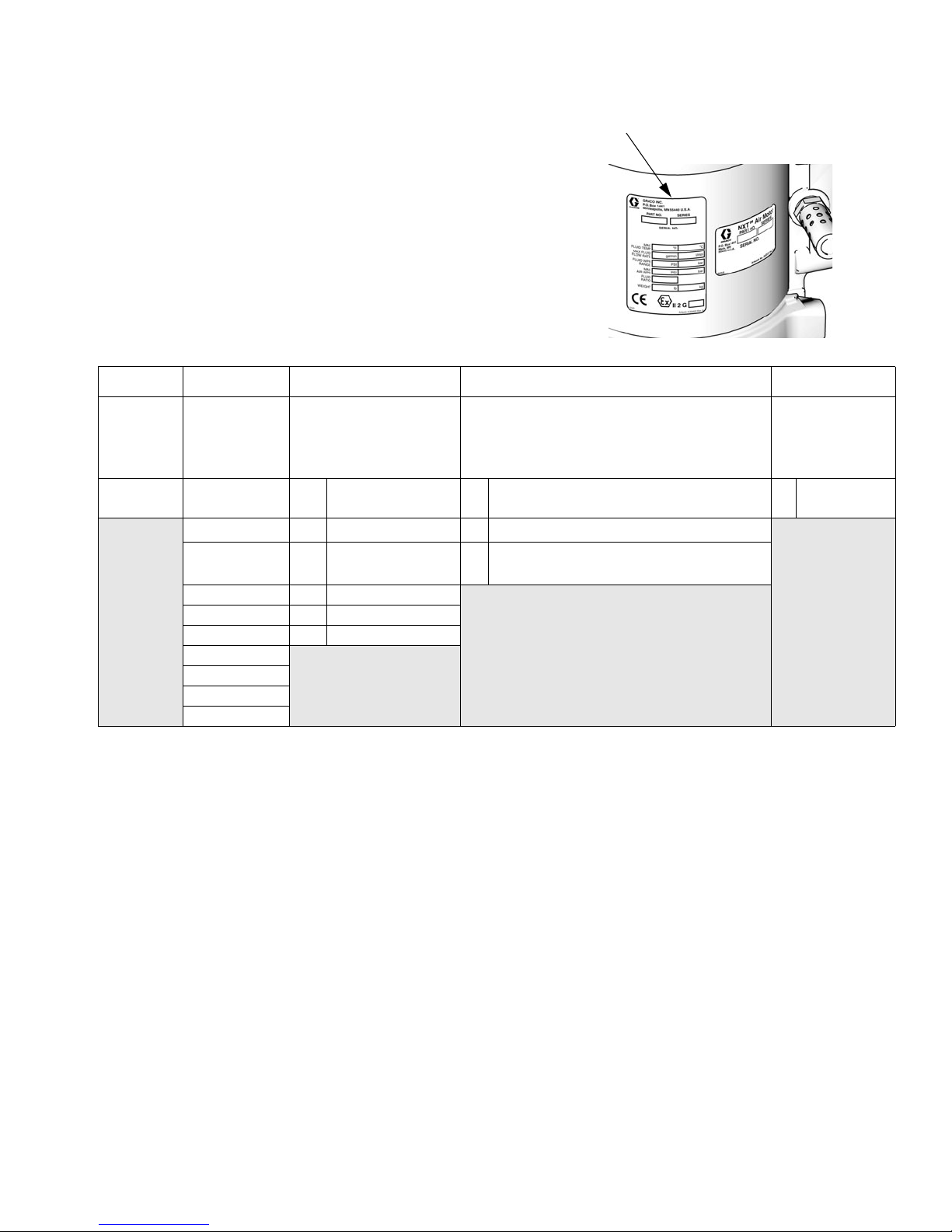
Pump Part Number Matrix
Pump Part Number Matrix
Check your pump’s identification plate (ID) for the 6-digit part number.
Use the following matrix to define the construction of your pump, based
on the six digits. For example, Part No. W 1 5 A A S represents a wet cup
pump (W), 15 to 1 ratio (15), 25 cc lower (A), 3 UHMWPE/2 PTFE packings with chromex rod coating, no data monitoring, low noise exhaust
(A), and stainless steel construction (S).
ID
W15 A A S
Second and
Third Digits
First Digit
(Wet cup)
W10A25 cc A 3:2/Chromex/No Monitoring/Low Noise S Stainless
(pressure
ratio - XX:1)
15 B 50 cc B
18 C 75 cc E
23 D 100 cc
24 E 125 cc
28 F 150 cc
30
36
45
48
Fourth Digit
(Displacement pump
volume per cycle*)
(Packings - X UHMWPE:X PTFE/
Data Monitoring/Exhaust)
3:2/Chromex/DataTrak
3:2/Chromex/DataTrak
Only/Low Noise
Fifth Digit
Piston Rod Coating/
™
/Low Noise
™
Cycle Count
Sixth Digit
(lower
material)
steel
ti12922a
* Cycle refers to combination of one upstroke and one downstroke.
312794F 3
Page 4

Pump Models
Pump Models
Maximum Fluid
Air
Model, Series
W10CAS, Series A M04LN0
W10CBS, Series A M04LT0
W15AAS, Series A M02LN0 LW025A 1500 (10.3, 103) 0.4 (1.5) 1/2 in. npt 3/8 in. npt 1/4 npt(f)
W15BAS, Series A M04LN0
W15BBS, Series A M04LT0
W15FAS, Series A M12LN0
W15FBS, Series A M12LT0
W18EAS Series A M12LN0
W18EBS, Series A M12LT0
W23DAS, Series A M12LN0
W23DBS, Series A M12LT0
W24FAS, Series A M18LN0
W24FBS, Series A M18LT0
W28EAS, Series A M18LN0
W28EBS, Series A M18LT0
W30AAS, Series A M04LN0
W30ABS, Series A M04LT0
W30CAS, Series A M12LN0
257463 †, Series A M12LN0
W36DAS, Series A M18LN0
W36DBS, Series A M18LT0
W45BAS, Series A M12LN0
W45BBS, Series A M12LT0
262287 †, Series A M12LN0
262392 †, Series A M12FN0
W48CAS, Series A M18LN0
W48CBS, Series A M18LT0
Motor
Displacement
Pump
LW075A 1000 (6.9, 69) 1.2 (4.5) 3/4 in. npt 3/8 in. npt 1/4 npt(f)
LW050A 1500 (10.3, 103) 0.8 (3.0) 3/4 in. npt 3/8 in. npt 1/4 npt(f)
LW150A 1500 (10.3, 103) 2.4 (9.0) 1 in. npt 3/4 in. npt 1/2 npt(f)
LW125A 1800 (12.4, 124) 2.0 (7.5) 1 in. npt 1/2 in. npt 1/2 npt(f)
LW100A 2300 (15.8, 158) 1.6 (6.0) 3/4 in. npt 3/8 in. npt 1/2 npt(f)
LW150A 2400 (16.5, 165) 2.4 (9.0) 1 in. npt 3/4 in. npt 1/2 npt(f)
LW125A 2800 (19.3, 193) 2.0 (7.5) 1 in. npt 1/2 in. npt 1/2 npt(f)
LW025A 3000 (20.7, 207) 0.4 (1.5) 1/2 in. npt 3/8 in. npt 1/4 npt(f)
LW075A 3000 (20.7, 207) 1.2 (4.5) 3/4 in. npt 3/8 in. npt 1/2 npt(f)W30CBS, Series A M12LT0
LW100A 3600 (24.8, 248) 1.6 (6.0) 3/4 in. npt 3/8 in. npt 1/2 npt(f)
LW050A 4500 (31.0, 310) 0.8 (3.0) 3/4 in. npt 3/8 in. npt 1/2 npt(f)
LW075A 4800 (33.1, 331) 1.2 (4.5) 3/4 in. npt 3/8 in. npt 1/2 npt(f)
Working Pressure
psi (MPa, bar)
Flow Rate
at 60 cpm
gpm (lpm)
Fluid
Inlet
Fluid
Outlet Air Inlet
† Flush Kit Pumps do not utilize the part number matrix.
4 312794F
Page 5

Warnings
Warnings
The following warnings are for the setup, use, grounding, maintenance, and repair of this equipment. The exclamation point symbol alerts you to a general warning and the hazard symbol refers to procedure-specific risk. Refer back
to these warnings. Additional, product-specific warnings may be found throughout the body of this manual where
applicable.
WARNING
FIRE AND EXPLOSION HAZARD
Flammable fumes, such as solvent and paint fumes, in work area can ignite or explode. To help prevent
fire and explosion:
• Use equipment only in well ventilated area.
• Eliminate all ignition sources; such as pilot lights, cigarettes, portable electric lamps, and plastic drop
cloths (potential static arc).
• Keep work area free of debris, including solvent, rags and gasoline.
• Do not plug or unplug power cords, or turn power or light switches on or off when flammable fumes
are present.
• Ground all equipment in the work area. See Grounding instructions.
• Use only grounded hoses.
• Hold gun firmly to side of grounded pail when triggering into pail.
• If there is static sparking or you feel a shock, stop operation immediately. Do not use equipment
until you identify and correct the problem.
• Keep a working fire extinguisher in the work area.
EQUIPMENT MISUSE HAZARD
Misuse can cause death or serious injury.
• Do not operate the unit when fatigued or under the influence of drugs or alcohol.
• Do not exceed the maximum working pressure or temperature rating of the lowest rated system
component. See Technical Data in all equipment manuals.
• Use fluids and solvents that are compatible with equipment wetted parts. See Technical Data in all
equipment manuals. Read fluid and solvent manufacturer’s warnings. For complete information
about your material, request MSDS forms from distributor or retailer.
• Check equipment daily. Repair or replace worn or damaged parts immediately with genuine manufacturer’s replacement parts only.
• Do not alter or modify equipment.
• Use equipment only for its intended purpose. Call your distributor for information.
• Route hoses and cables away from traffic areas, sharp edges, moving parts, and hot surfaces.
• Do not kink or over bend hoses or use hoses to pull equipment.
• Keep children and animals away from work area.
• Comply with all applicable safety regulations.
SKIN INJECTION HAZARD
High-pressure fluid from gun, hose leaks, or ruptured components will pierce skin. This may look like just
a cut, but it is a serious injury that can result in amputation. Get immediate surgical treatment.
• Do not point gun at anyone or at any part of the body.
• Do not put your hand over the spray tip.
• Do not stop or deflect leaks with your hand, body, glove, or rag.
• Do not spray without tip guard and trigger guard installed.
• Engage trigger lock when not spraying.
• Follow Pressure Relief Procedure in this manual, when you stop spraying and before cleaning,
checking, or servicing equipment.
312794F 5
Page 6

Related Manuals
PRESSURIZED EQUIPMENT HAZARD
Fluid from the gun/dispense valve, leaks, or ruptured components can splash in the eyes or on skin and
cause serious injury.
• Follow Pressure Relief Procedure in this manual, when you stop spraying and before cleaning,
• Tighten all fluid connections before operating the equipment.
• Check hoses, tubes, and couplings daily. Replace worn or damaged parts immediately.
MOVING PARTS HAZARD
Moving parts can pinch or amputate fingers and other body parts.
• Keep clear of moving parts.
• Do not operate equipment with protective guards or covers removed.
• Pressurized equipment can start without warning. Before checking, moving, or servicing equipment,
TOXIC FLUID OR FUMES HAZARD
Toxic fluids or fumes can cause serious injury or death if splashed in the eyes or on skin, inhaled, or
swallowed.
• Read MSDS’s to know the specific hazards of the fluids you are using.
• Store hazardous fluid in approved containers, and dispose of it according to applicable guidelines.
• Always wear impervious gloves when spraying or cleaning equipment.
WARNING
checking, or servicing equipment.
follow the Pressure Relief Procedure in this manual. Disconnect power or air supply.
PERSONAL PROTECTIVE EQUIPMENT
You must wear appropriate protective equipment when operating, servicing, or when in the operating
area of the equipment to help protect you from serious injury, including eye injury, inhalation of toxic
fumes, burns, and hearing loss. This equipment includes but is not limited to:
• Protective eyewear
• Clothing and respirator as recommended by the fluid and solvent manufacturer
•Gloves
• Hearing protection
Related Manuals
Manual Description
312792 Merkur Displacement Pump
312796
312797 Merkur Non-Heated Spray Packages
312798
313255 Merkur Heated Spray Packages
™
NXT
Air Motor
Merkur Electrostatic Spray Packages,
Ambient and Heated
6 312794F
Page 7
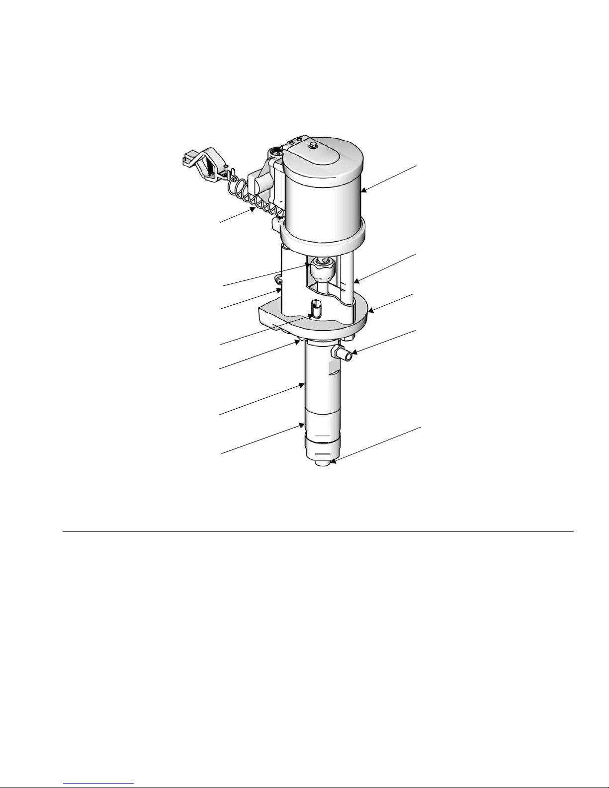
Component Identification
A
Component Identification
N
K
L
H
B
M
G
F
FIG. 1. Component Identification
Key:
A Ground Wire
B TSL Reservoir
C Wet Cup (not visible, under TSL reservoir)
D Fluid Outlet
E Fluid Inlet
F Lower Cylinder
G Upper Cylinder
H Tie Rod Shield
J Displacement Pump Adapter
KTie Rod
L Coupling Nut
MJam Nut
N Air Motor
J
D
E
ti11700a
312794F 7
Page 8
Installation
Installation
General Information
Reference numbers and letters in parentheses in
the text refer to the callouts in the figures and the
parts drawing.
Always use Genuine Graco Parts and Accessories,
available from your Graco distributor. If you supply
your own accessories, be sure they are adequately
sized and pressure-rated for your system.
Prepare the Operator
All persons who operate the equipment must be trained
in the operation of all system components as well as the
proper handling of all fluids. All operators must thoroughly read all instruction manuals, tags, and labels
before operating the equipment.
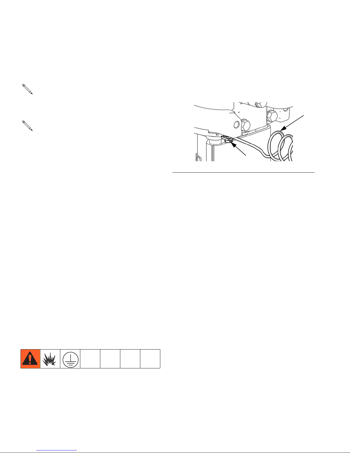
Prepare the Site
Pump: See F
attached and tightened securely to the air motor. Connect the other end of the ground wire (U) to a true earth
ground.
FIG. 2. Ground screw and wire
Air and fluid hoses: Static electricity may build up
when fluids flow through pumps, hoses, and sprayers. At
least one hose must be electrically conductive, with a
maximum of 500 ft. (150 m) combined hose length to
ensure grounding continuity. Check electrical resistance
of hose. If total resistance to ground exceeds 25 megohms, replace hose immediately.
IG. 2. Verify that the ground screw (GS) is
U
GS
ti12914a
Ensure that you have an adequate compressed air
supply.
Bring a compressed air supply line from the air compressor to the pump location. Be sure all air hoses are
properly sized and pressure-rated for your system. Use
only electrically conductive hoses.
Keep the site clear of any obstacles or debris that could
interfere with the operator's movement.
Have a grounded, metal pail available for use when
flushing the system.
Grounding
The equipment must be grounded. Grounding reduces
the risk of static and electric shock by providing an
escape wire for the electrical current due to static build
up or in the event of a short circuit.
Air compressor: follow manufacturer’s recommendations.
Spray gun / Dispense valve: Ground the spray gun
through connection to a Graco-approved grounded fluid
hose.
Fluid supply container: follow local code.
Object being sprayed: follow local code.
Solvent pails used when flushing: follow local code.
Use only conductive metal pails, placed on a grounded
surface. Do not place the pail on a nonconductive surface, such as paper or cardboard, which interrupts
grounding continuity.
To maintain grounding continuity when flushing or
relieving pressure: hold metal part of the spray
gun/dispense valve firmly to the side of a grounded
metal pail, then trigger the gun/valve.
8 312794F
Page 9
Installation
Mount the Pump
Mount the pump only to Graco wall bracket 15T795, or
to a Graco cart, available from your distributor. Pump
dimensions are shown on page 29. For wall mounted
pumps, follow these guidelines:
1. Be sure the wall can support the weight of the
pump, bracket, hoses and accessories, as well as
the stress caused during operation.
2. Position the wall bracket about 1.2-1.5 m (4-5 ft)
above the floor. For ease of operation and service,
make sure the pump air inlet, fluid inlet, and fluid
outlet ports are easily accessible.
3. Using the wall bracket as a template, drill 10 mm
(0.4 in.) mounting holes in the wall. Wall mounting
dimensions are shown on page 30.
4. Attach the bracket to the wall. Use 9 mm (3/8 in.)
screws that are long enough to keep the pump from
vibrating during operation.
NOTE: Be sure the bracket is level.
• Pump air regulator (H): controls pump speed and
outlet pressure. Locate it close to the pump.
• Air line filter (B): removes harmful dirt and mois-
ture from compressed air supply.
• Air shutoff valve (A): isolates air line accessories
for servicing. Locate upstream from all other air line
accessories.
• Gun air regulator (D): controls air pressure to the
air-assisted spray gun.
Fluid Line
• Fluid filter (P): with a 60 mesh (250 micron) stain-
less steel element to filter particles from the fluid as
it leaves the pump.
• Fluid drain valve (W): required in your system, to
relieve fluid pressure in the hose and gun.
• Gun or valve (L): dispenses the fluid. The gun
shown in F
to medium viscosity fluids.
IG. 3 is an air-assisted spray gun for light
Air and Fluid Hoses
Be sure all air hoses (N) and fluid hoses (M) are properly sized and pressure rated for your system. See F
3. Use only electrically conductive fluid hoses.
IG.
Accessories
Install the following accessories in the order shown in
F
IG. 3, using adapters as necessary.
Air Line
• Bleed-type master air valve (E): required in your
system to relieve air trapped between it and the air
motor and gun when the valve is closed.
Trapped air can cause the pump to cycle unexpectedly,
which could result in serious injury from splashing or
moving parts.
• Fluid line swivel (K): for easier gun movement.
• Suction kit (V): enables the pump to draw fluid from
a container.
Be sure the valve is easily accessible from the pump
and located downstream from the air regulator.
312794F 9
Page 10

Installation
Typical Installation
A Air Shutoff Valve
B Air Filter (optional accessory)
C Gun Air Pressure Gauge
D Gun Air Pressure Regulator
E Bleed Type Master Air Valve
F DataTrak
G Pump Air Pressure Gauge
H Pump Air Pressure Regulator
J Solenoid Release Button
(not visible)
KGun Swivel
L Air-Assisted Spray Gun
M Gun Fluid Supply Hose
N Gun Air Supply Hose
P Fluid Filter
R Pump Fluid Outlet
S Grounding Wire
T Wet-Cup (not visible, see F
U Pump Fluid Inlet
V Suction Hose
W Fluid Drain Valve
B
C
D
IG. 4, page 11)
A
F
G
G15 Spray Gun Shown
with Supply Hose
K
M
E
P
L
R
N
W
V
H
J
S
T
U
FIG. 3. Typical Installation. (Graco Cart-Mounted Package Shown.)
10 312794F
ti12800a
Page 11

Operation
Operation
Pressure Relief Procedure
Trapped air can cause the pump to cycle unexpectedly,
which could result in serious injury from splashing or
moving parts.
1. Engage the trigger lock.
2. Close the bleed-type master air valve.
3. Disengage the trigger lock.
4. Hold a metal part of the gun firmly to a grounded
metal pail. Trigger the gun to relieve pressure.
5. Engage the trigger lock.
6. Open all fluid drain valves in the system, having a
waste container ready to catch drainage. Leave
drain valve(s) open until you are ready to spray
again.
Trigger Lock
Always engage the trigger lock when you stop spraying
to prevent the gun from being triggered accidentally by
hand or if dropped or bumped.
Wet Cup
Before starting, fill wet cup (T) 1/3 full with Graco Throat
Seal Liquid (TSL) or compatible solvent.
7. If you suspect the spray tip or hose is clogged or
that pressure has not been fully relieved after following the steps above, VERY SLOWLY loosen tip
guard retaining nut or hose end coupling to relieve
pressure gradually, then loosen completely. Clear
hose or tip obstruction.
Flush Before Using Equipment
The equipment was tested with lightweight oil, which is
left in the fluid passages to protect parts. To avoid contaminating your fluid with oil, flush the equipment with a
compatible solvent before using the equipment. See
Maintenance, page 13.
T
ti11927a
FIG. 4. Fill Wet Cup
312794F 11
Page 12

Operation
Prime and Adjust the Pump
1. Lock gun trigger. Remove tip guard and spray tip
from gun. Refer to gun manual.
2. Close gun air regulator and pump air regulator (H)
by turning knobs counterclockwise reducing pressure to zero. Close bleed-type air valve (E). Also
verify that all drain valves are closed.
3. Check that all fittings throughout system are tightened securely.
4. Position pail close to pump. Do not stretch suction
hose tight/let it hang to assist fluid flow into pump.
D
12. Use the air regulator to control the pump speed and
the fluid pressure. Always use the lowest air pressure necessary to get the desired results. Higher
pressures cause premature tip/nozzle and pump
wear.
NOTICE
Never allow the pump to run dry of the fluid being
pumped. A dry pump quickly accelerates to a high
speed, possibly damaging itself. If your pump accelerates quickly, or is running too fast, stop it immediately and check the fluid supply. If the supply
container is empty and air has been pumped into
the lines, refill the container and prime the pump
and the lines with fluid, or flush and leave it filled
with a compatible solvent. Be sure to eliminate all
air from the fluid system.
Shutdown and Care of the Pump
For a brief shutdown, relieve the pressure, page 11.
Stop the pump at the bottom of its stroke to prevent fluid
from drying on the exposed displacement rod and damaging the throat packings.
E
F
IG. 5
5. Hold metal part of gun (L) firmly to side of grounded
metal pail, unlock trigger, and hold trigger open.
6. Pumps with runaway protection: Enable the
prime/flush function by pushing the prime/flush button on the DataTrak.
7. Open bleed-type air valve (E). Slowly open the
pump air regulator (H) until the pump starts.
8. Cycle pump slowly until all air is pushed out and the
pump and hoses are fully primed.
9. Pumps with runaway protection: Disable the
prime/flush function by pushing the prime/flush button on the DataTrak.
10. Release gun trigger and lock trigger safety. Pump
should stall against pressure.
H
ti11882a
For a longer shutdown, or overnight, always flush the
pump before the fluid dries on the displacement rod.
Relieve the pressure, page 11.
11. With the pump and lines primed, and with adequate
air pressure and volume supplied, the pump will
start and stop as you open and close the gun/valve.
12 312794F
Page 13

Maintenance
Maintenance
Preventive Maintenance
Schedule
The operating conditions of your particular system
determine how often maintenance is required. Establish
a preventive maintenance schedule by recording when
and what kind of maintenance is needed, and then
determine a regular schedule for checking your system.
Tighten Threaded Connections
Before each use, check all hoses for wear or damage.
Replace as necessary. Check that all threaded connections are tight and leak-free.
Flush the Pump
3. Place siphon tube in grounded metal pail containing
cleaning fluid.
4. Set pump to lowest possible fluid pressure, and start
pump.
5. Hold a metal part of the gun firmly to a grounded
metal pail.
6. Units with runaway protection only: enable the
prime/flush function by pushing the prime/flush button on the DataTrak.
7. Trigger gun. Flush system until clear solvent flows
from gun.
8. Units with runaway protection only: disable the
prime/flush function by pushing the prime/flush button on the DataTrak.
9. Follow Pressure Relief Procedure, page 11.
10. Clean the tip guard, spray tip, and fluid filter element
separately, then reinstall them.
Read all Warnings. Follow all Grounding instructions.
See page 8.
Flush the pump:
• Before first use
• When changing colors or fluids
• Before repairing equipment
• Before fluid dries or settles out in a dormant pump
(check the pot life of catalyzed fluids)
• At the end of the day
• Before storing the pump.
Flush at the lowest pressure possible. Flush with a fluid
that is compatible with the fluid you are pumping and
with the wetted parts in your system. Check with your
fluid manufacturer or supplier for recommended flushing
fluids and flushing frequency.
11. Clean inside and outside of suction tube.
Wet Cup
Fill the wet cup one-half full with Graco Throat Seal Liquid (TSL). Maintain level daily.
1. Follow Pressure Relief Procedure, page 11.
2. Remove tip guard and spray tip from gun. Refer to
separate gun manual.
312794F 13
Page 14

Troubleshooting
Troubleshooting
NOTE: Check all possible problems and causes before
disassembling the pump.
Relieve the pressure before checking or servicing
the equipment.
Problem Cause Solution
Pump output low on both strokes. Restricted air supply lines. Clear any obstructions; be sure all shutoff
valves are open; increase pressure, but do
not exceed maximum working pressure.
Exhausted fluid supply. Refill and reprime pump.
Clogged fluid outlet line, valves, etc. Clear.
Worn piston packing. Replace. See displacement pump manual
312792.
Pump output low on only one stroke. Held open or worn ball check valves. Check and repair.
Worn piston packings. Replace.
No output. Improperly installed ball check valves. Check and repair.
Pump operates erratically. Exhausted fluid supply. Refill and reprime pump.
Held open or worn ball check valves. Check and repair.
Worn piston packing. Replace.
Pump will not operate. Restricted air supply lines. Clear any obstructions; be sure all shut off
valves are open; increase pressure, but do
not exceed maximum working pressure.
Exhausted fluid supply. Refill and reprime pump.
Clogged fluid outlet line, valves, etc. Clear.
Damaged air motor. See air motor manual 312796.
Fluid dried on piston rod. Disassemble and clean pump. See page 15
and manual 312792. In future, stop pump at
bottom of stroke.
Runaway solenoid has tripped. Retract solenoid. See air motor manual
312796.
14 312794F
Page 15

Repair
Repair
6. Lower the coupling nut (9) enough to remove the
coupling collars (10), and then remove the coupling
nut (9).
General Information
• Reference numbers and letters in parentheses in
the text refer to the callouts in the figures and the
parts drawing.
• Always use Genuine Graco Parts and Accessories,
available from your Graco distributor. If you supply
your own accessories, be sure they are adequately
sized and pressure rated for your system.
Disconnect the Displacement
Pump
1. Stop the pump in the middle of the stroke.
2. Flush the pump, if possible. (See page 13). Relieve
the pressure. (See page 11).
3. Disconnect the air and fluid hoses and the ground
wire (13).
4. Remove the tie rod shield (11).
9 10
ti12812a
7. Pull up on TSL reservoir (7) to remove.
8. Use a hammer and
brass rod to loosen the
jam nut (4). Unscrew
the jam nut as far as
possible.
9. Unscrew the displacement pump by hand
and place on work
bench.
ti12813a
ti12816a
5. Hold the flats of the air
motor piston rod with a
wrench. Use another
wrench to loosen the
coupling nut (9).
Threads are very sharp. Use a rag to protect hands
when hand turning or carrying the pump.
ti12815a
312794F 15
Page 16

Repair
Reconnect the Displacement
Pump
1. Tilt the air motor onto its back, then hand turn the
displacement pump into the adapter plate. Set the
pump upright again.
2. Hold the air motor piston rod up with one hand. With
your other hand, put the coupling nut (9) on the displacement rod.
3. Put the coupling
collars (10) into
the coupling nut
(9) so large
flanges point
upward.
4. Gently let the air
motor piston rod
drop onto the displacement rod.
Hand tighten the
coupling nut (9).
10
9
ti12817a
6. Align fluid outlet as shown and tighten the jam nut.
7. Align the TSL reservoir (7) and push it down into
place.
8. Hold the flats of the motor rod with a wrench. Use
another wrench to tighten the coupling nut (9).
Torque according to the following table.
Displacement Pump Torque
LW025A
LW050A–LW150A
23-26 ft-lb (31-35 N•m)
75-80 ft-lb (102-108 N•m)
5. Screw the displacement pump into the adapter plate
(3) until the cylinder top is flush with the top of the
adapter plate.
Cylinder, not
wet cup, should
be flush with
plate.
ti12814a
F
IG. 6. Align cylinder and adapter plate.
16 312794F
Page 17

Repair
Disconnect the Air Motor
1. Flush the pump, if possible. (See page 13.) Relieve
the pressure. (See page 11.)
2. Disconnect the air and fluid hoses, the ground wire
(13), and the tie rod shield (11).
3. Hold the flats of the air motor piston rod with a
wrench. Use another wrench to loosen the coupling
nut (9).
4. Use a socket to remove the tie rod nuts (6): 13 mm
for M02xxx, 23 mm for all others.
5. Use a 13 mm socket to remove the top two mounting screws (MS).
6. Lift up on the air motor to remove it. The tie rods (5)
and drip shield (12) will remain attached.
Cart Mount: Remove the two screws on the arms
and tip back or remove the air control panel for easier removal of the air motor.
See manual 312796 for air motor service and parts
information,
Reconnect the Air Motor
1. Slide the drip shield (12) onto the tie rods (5).
2. Screw the tie rods (5) into the bottom cover of the air
motor. Torque according to the following table:
Motor Torque
M02xxx
All Other Sizes
3. As needed for the larger air motors, use two people
to reattach. Align the tie rods (5) with the holes in
the pump adapter (3). Carefully lower the air motor
into place.
4. Attach the tie rod nuts (6) and torque according the
following table:
5-10 ft-lb (7-13.5 N•m)
50-55 ft-lb (68-75 N•m)
5
11
7. Slide the drip shield (12) off
the tie rods (5).
8. Use a socket on the flats of
the tie rods (5) to remove
them from the bottom cover of
the air motor.
MS
6
ti12819a
Motor Torque
M02xxx
All Other Sizes
5. Tighten the mounting screws.
6. Hand tighten the coupling nut, then torque according to the following table:
Motor Torque
M02xxx
All Other Sizes
7. Connect the air and fluid hoses, the ground wire,
and the tie rod shield.
15-20 ft-lb (20-27 N•m)
50-60 ft-lb (68-81 N•m)
23-26 ft-lb (31-35 N•m)
75-80 ft-lb (102-108 N•m)
312794F 17
ti12916a
12
Page 18

Pump Parts
Pump Parts
1
12*
10*
3
9*
7*
8*
1
Torque varies by air motor size.
M02xxx: 5-10 ft-lb (7-13.5 N•m)
All others: 50-55 ft-lb (68-75 N•m)
2
Torque varies by air motor size.
M02xxx: 15-20 ft-lb (20-27 N•m)
All others: 50-60 ft-lb (68-81 N•m)
3
Torque varies by displacement pump size.
25 cc: 23-26 ft-lb (31-35 N•m)
All others: 75-80 ft-lb (102-108 N•m)
4
Torque to 70-75 ft-lb (95-102 N•m)
11*
1
5*
3*
2
6*
4
4
2
18 312794F
ti12810a
Page 19

Pump Parts
NOTES:
• For parts that vary by model, see page 20.
• For Flush Kit Pumps 262287 and 262392, see manual 310863 for additional parts information.
• For Flush Kit Pump 257463, see manual 313289 for
additional parts information.
Pump Parts
Ref. Part No. Description Qty.
1 See Table MOTOR 1
2 See Table DISPLACEMENT PUMP 1
3* See Table ADAPTER, pump 1
4 See Table NUT, jam 1
5* ROD, tie
15M661 M02xxx motor 3
15M662 All other motor sizes 3
6* NUT, tie rod
104541 M02xxx motor 3
15U606 All other motor sizes 3
7* See Table RESERVOIR, TSL 1
8* See Table ADAPTER, 1/2-20 ID X M22 x
1.5 OD
Ref. Part No. Description Qty.
9* NUT, coupling
15M758 LW025x displacement
pumps
15T311 All other pump sizes 1
10* ----- COLLAR, coupling; see page
21 to order package of 10
11* See Table SHIELD, tie rod 1
12* See Table SHIELD, drip 1
13 WIRE, grounding assembly, not
shown
238909 All Wxxxxx Model Pumps 1
244524 Pump Models 257463,
262287, and 262392 only
----- Not sold separately.
* Included in Connecting Kit. See page 21 to order the
correct kit for your pump.
NOTE: Replacement Warning labels, signs, tags, and
cards are available at no cost.
1
2
1
312794F 19
Page 20

Pump Parts
Parts That Vary by Model
Motor
Model
W10CAS M04LN0
W10CBS M04LT0
W15AAS
W15AES
W15BAS M04LN0
W15BBS M04LT0
W15FAS M12LN0
W15FBS M12LT0
W18EAS M12LN0
W18EBS M12LT0
W23DAS M12LN0
W23DBS M12LT0
W24FAS M18LN0
W24FBS M18LT0
W28EAS M18LN0
W28EBS M18LT0
W30AAS M04LN0
W30ABS M04LT0
W30CAS M12LN0
257463 M12LN0
W36DAS M18LN0
W36DBS M18LT0
W45BAS M12LN0
W45BBS M12LT0
(1)
M02LN0 2.5 LW025A 15R862 24A634 24A620 24A957 15T461
262287 M12LN0
262392
W48CAS M18LN0
W48CBS M18LT0
M12FN0
Motor
Piston
Diam.
(in.)
Displacement
Pump (2)
3.5 LW075A 15R978 24A636 24A623 15M675 24A958 15T462
3.5 LW050A 15R977 24A635 24A622 15M675 24A958 15T462
6.0 LW150A 15T395 24A639 24A628 24A959 15V028
6.0 LW125A 15T394 24A638 24A627
6.0 LW100A 15T393 24A637 24A626 24A959 15V028
7.5 LW150A 15T395 24A639 24A628
7.5 LW125A 15T394 24A638 24A627 24A959 15V028
3.5 LW025A 15R863 24A634 24A621
6.0 LW075A 15T392 24A636 24A625 24A959 15V028W30CBS M12LT0
7.5 LW100A 15T393 24A637 24A626
6.0 LW050A 15T391 24A635 24A624 24A959 15V028
7.5 LW075A 15T392 24A636 24A625
Pump
Adapter (3)
Jam Nut
(4)
TSL Reservoir
(7, includes
o-ring)
Adapter
(8)
Tie Rod
Shield
(11, includes
screw)
24A959 15V028
24A959 15V028
24A958 15T462
24A959 15V028
24A959 15V028
Drip Shield
(12)
20 312794F
Page 21

Repair Kits
Repair Kits
LW025A LW050A LW075A
2.5 in.
Kit Description
Wet-Cup O-Ring
Package of 10 24A630 24A631 24A631 24A632 24A633 24A633
Coupling Collars (10)
Package of 10
Connecting Kit
Includes pump adapter (3),
three tie rods (5), three tie rod
nuts (6), TSL reservoir and
o-ring (7), adapter (8),
coupling nut (9), two coupling
collars (10), tie rod shield and
screw (11), and drip shield
(12).
motor
24A281 24A282 24A283 24A285 24A284 24A286 24A287 24A288 24A289
3.5 in.
motor
24A618 24A619 24A619 24A619 24A619 24A619
3.5 in.
motor
6-7.5 in
motor
3.5 in.
motor
6-7.5 in
motor
LW100A LW125A LW150A
NOTE:
For displacement pump repair kits, see manual 312792.
For air motor repair kits, see manual 312796.
312794F 21
Page 22

Performance Charts
Performance Charts
Model W10xxx
10:1 Ratio, 75 cc/cycle
1000
(7, 70)
A
800
(5.5, 55)
600
(4, 40)
400
(3, 30)
B
C
200
(1.4, 14)
Fluid Outlet Pressure psi (MPa, bar)
0
0
0.2
(0.75)
10
20 30
0.4
(1.5)
Cycles per Minute
40
A
B
0.6
(2.3)
0.8
(3.0)
50 60
C
1.0 1.2
(3.8)
(4.5)
16
(0.45)
14
(0.4)
12
(0.34)
10
(0.28)
8
(0.23)
6
(0.17)
4
(0.1)
2
(.06)
/min)
3
Air Flow scfm (m
Fluid Flow gpm (lpm) tested in No. 10 weight oil
Model W15Axx
15:1 Ratio, 25 cc/cycle
1400
8
(10, 100)
15
A
1200
(8, 80)
1000
(7, 70)
B
800
(5.5, 55)
600
(4, 40)
400
(3, 30)
200
(1.4, 14)
Fluid Outlet Pressure psi (MPa, bar)
C
0
0
0.05
(0.2)
0.1
(0.4)
0.15
(0.6)
Cycles per Minute
23 30
0.2
(0.75)
0.25
(0.9)
A
B
C
38 45 53
A
B
C
0.3
(1.1)
0.35
(1.3)
KEY
=
100 psi (0.7 MPa, 7 bar)
=
70 psi (0.5 MPa, 5 bar)
=
40 psi (0.3 MPa, 3 bar)
= fluid flow
= air consumption
9
(0.25)
8
(0.23)
7
(0.2)
6
(0.17)
5
(0.14)
4
(0.1)
3
(.08)
2
(.06)
1
(.03)
/min)
3
Air Flow scfm (m
Fluid Flow gpm (lpm) tested in No. 10 weight oil
22 312794F
Page 23

Model W15Bxx
15:1 Ratio, 50 cc/cycle
815
1600
(11, 110)
1400
(10, 100)
1200
(8, 80)
1000
(7, 70)
800
(5.5, 55)
600
(4, 40)
400
(3, 30)
200
(1.4, 14)
Fluid Outlet Pressure psi (MPa, bar)
A
B
C
0
0
0.1
(0.4) (0.8) (1.1) (1.5) (1.9) (2.3) (2.6) (3.0)
0.2
23
0.3
Cycles per Minute
30 38
45 53 61
C
0.4
0.5 0.6
B
0.7
A
0.8
Performance Charts
18
(0.5)
16
(0.45)
14
(0.4)
12
(0.34)
10
(0.28)
8
(0.23)
6
(0.17)
4
(0.1)
2
(.06)
/min)
3
Air Flow scfm (m
Fluid Flow gpm (lpm) tested in No. 10 weight oil
Model W15Fxx
15:1 Ratio, 150 cc/cycle
1600
(11, 110)
1400
(10, 100)
1200
(8, 80)
1000
(7, 70)
800
(5.5, 55)
600
(4, 40)
400
(3, 30)
200
(1.4, 14)
Fluid Outlet Pressure psi (MPa, bar)
A
B
C
0
0
13
0.5 1.0
(1.9)
25
(3.8)
Cycles per Minute
38
51 63
B
1.5
(5.7) (7.6)
2.0
A
C
2.5
(9.5)
KEY
A
=
100 psi (0.7 MPa, 7 bar)
B
=
70 psi (0.5 MPa, 5 bar)
C
=
40 psi (0.3 MPa, 3 bar)
= fluid flow
= air flow
40
(1.1)
/min)
30
(0.9)
20
(0.6)
10
(0.3)
3
Air Flow scfm (m
Fluid Flow gpm (lpm) tested in No. 10 weight oil
312794F 23
Page 24

Performance Charts
Model W18xxx
18:1 Ratio, 125 cc/cycle
15
2000
(14, 140)
1600
(11, 110)
1200
(8, 80)
A
B
Cycles per Minute
30 45
B
A
61
40
(1.1)
30
(0.9)
/min)
3
800
(5.5, 55)
C
400
(3, 30)
Fluid Outlet Pressure psi (MPa, bar)
0
0
0.5
(1.9)
Fluid Flow gpm (lpm) tested in No. 10 weight oil
Model W23xxx
23:1 Ratio, 100 cc/cycle
3000
(21, 210)
815
1.0
(3.8)
Cycles per Minute
23
30 38
C
1.5
(5.7)
45 53 61
2.0
(7.6)
20
(0.6)
10
(0.3)
Air Flow scfm (m
KEY
A
=
100 psi (0.7 MPa, 7 bar)
B
=
70 psi (0.5 MPa, 5 bar)
C
=
40 psi (0.3 MPa, 3 bar)
= fluid flow
= air flow
2500
(17, 170)
2000
(14, 140)
1500
(10, 100)
1000
(7, 70)
500
(3, 30)
Fluid Outlet Pressure psi (MPa, bar)
A
B
C
0
0
0.2
(0.75)
0.4
(1.5) (2.3) (3.0)
0.6
Fluid Flow gpm (lpm) tested in No. 10 weight oil
24 312794F
0.8
1.0
(3.8)
1.2
(4.5)
A
B
C
1.4 1.6
(5.3)
(6.1)
40
(1.1)
30
(0.9)
20
(0.6)
10
(0.3)
/min)
3
Air Flow scfm (m
Page 25

Model W24xxx
24:1 Ratio, 150 cc/cycle
13
3000
(21, 210)
2500
(17, 170)
A
2000
(14, 140)
1500
(10, 100)
1000
(7, 70)
500
(3, 30)
B
C
Cycles per Minute
25 38
51
A
B
C
63
Performance Charts
70
(2.0)
60
(1.7)
50
(1.4)
40
(1.1)
30
(0.9)
20
(0.6)
10
(0.3)
/min)
3
Air Flow scfm (m
Fluid Outlet Pressure psi (MPa, bar)
0
0
0.5
(1.9)
1.0
(3.8)
Fluid Flow gpm (lpm) tested in No. 10 weight oil
Model W28xxx
28:1 Ratio, 125 cc/cycle
3000
(21, 210)
15 30
A
2500
(17, 170)
2000
(14, 140)
1500
(10, 100)
B
C
1000
(7, 70)
500
(3, 30)
1.5
(5.7) (7.6)
2.0
Cycles per Minute
45
C
A
B
2.5
(9.5)
61
KEY
A
=
100 psi (0.7 MPa, 7 bar)
B
=
70 psi (0.5 MPa, 5 bar)
C
=
40 psi (0.3 MPa, 3 bar)
= fluid flow
= air flow
60
(1.7)
50
(1.4)
40
(1.1)
30
(0.9)
20
(0.6)
3
/min)
Air Flow scfm (m
10
(0.3)
Fluid Outlet Pressure psi (MPa, bar)
0
0
0.5
(1.9)
Fluid Flow gpm (lpm) tested in No. 10 weight oil
312794F 25
1.0
(3.8) (5.7)
1.5
2.0
(7.6)
2.5
(9.5)
Page 26

Performance Charts
Model W30Axx
30:1 Ratio, 25 cc/cycle
8
3000
(21, 210)
A
2500
(17, 170)
2000
(14, 140)
B
1500
(10, 100)
1000
(7, 70)
500
(3, 30)
Fluid Outlet Pressure psi (MPa, bar)
C
0
0.05
0
(0.2)
15
0.1
(0.4)
Cycles per Minute
23 30
0.15
(0.6)
0.2
(0.75)
38 45 53
0.25
(0.9)
0.3
(1.1)
A
B
C
0.35
(1.3)
61
0.4
(1.5)
18
(0.5)
16
(0.45)
14
(0.4)
12
(0.34)
10
(0.28)
8
(0.23)
6
(0.17)
4
(0.1)
2
(.06)
/min)
3
Air Flow scfm (m
Fluid Flow gpm (lpm) tested in No. 10 weight oil
Model W30Cxx, 257463
30:1 Ratio, 75 cc/cycle
10
3500
(24, 240)
3000
(21, 210)
2500
(17, 170)
2000
(14, 140)
1500
(10, 100)
1000
(7, 70)
500
(3, 30)
Fluid Outlet Pressure psi (MPa, bar)
0
0
A
B
C
0.2
(0.75)
Cycles per Minute
20 30
0.4
(1.5)
(2.3)
0.6
40
0.8
(3.0)
50 60
A
B
C
1.0
(3.8)
(4.5)
KEY
A
=
100 psi (0.7 MPa, 7 bar)
B
=
70 psi (0.5 MPa, 5 bar)
C
=
40 psi (0.3 MPa, 3 bar)
= fluid flow
= air flow
40
(1.1)
30
(0.9)
20
(0.6)
10
(0.3)
1.2
/min)
3
Air Flow scfm (m
Fluid Flow gpm (lpm) tested in No. 10 weight oil
26 312794F
Page 27

Model W36xxx
36:1 Ratio, 100 cc/cycle
815233038
4000
(28, 280)
3500
(24, 240)
3000
(21, 210)
2500
(17, 170)
2000
(14, 140)
1500
(10, 100)
1000
(7, 70)
500
(3, 30)
Fluid Outlet Pressure psi (MPa, bar)
A
B
C
0
0
0.2
(0.75)
0.4
(1.5)
0.6 0.8
(2.3)
Cycles per Minute
45
B
(3.0)
1.0
(3.8)
1.2
(4.5)
53 61
A
C
1.4
(5.3) (6.1)
1.6
Performance Charts
60
(1.7)
50
(1.4)
/min)
40
(1.1)
30
(0.9)
20
(0.6)
3
Air Flow scfm (m
10
(0.3)
Fluid Flow gpm (lpm) tested in No. 10 weight oil
Model W45xxx, 262287, 262392
45:1 Ratio, 50 cc/cycle
5000
(35, 350)
4000
(28, 280)
3000
(21, 210)
2000
(14, 140)
815233038455361
A
B
C
1000
(7, 70)
Cycles per Minute
KEY
A
=
100 psi (0.7 MPa, 7 bar)
B
=
70 psi (0.5 MPa, 5 bar)
C
=
40 psi (0.3 MPa, 3 bar)
= fluid flow
= air flow
50
(1.4)
A
40
(1.1)
3
B
C
30
(0.9)
20
(0.6)
10
(0.3)
/min)
Air Flow scfm (m
Fluid Outlet Pressure psi (MPa, bar)
0
0
0.1
(0.4)
0.2
(0.75)
Fluid Flow gpm (lpm) tested in No. 10 weight oil
312794F 27
0.3
(1.1)
0.4
(1.5)
0.5
(1.9)
0.6 0.8
(2.3)
0.7
(2.6)
(3.0)
Page 28

Performance Charts
Model W48xxx
48:1 Ratio, 75 cc/cycle
6000
(42, 420)
10
Cycles per Minute
20 30
40
50 60
5000
(35, 350)
4000
(28, 280)
A
B
3000
(21, 210)
2000
(14, 140)
1000
(7, 70)
Fluid Outlet Pressure psi (MPa, bar)
C
0
0
0.2
(0.75)
Fluid Flow gpm (lpm) tested in No. 10 weight oil
0.4
(1.5)
0.6
(2.3)
0.8
(3.0)
B
1.0
(3.8)
A
C
1.2
(4.5)
A
B
C
=
=
60
(1.7)
50
(1.4)
40
(1.1)
30
(0.9)
20
(0.6)
10
(0.3)
/min)
3
Air Flow scfm (m
KEY
=
100 psi (0.7 MPa, 7 bar)
70 psi (0.5 MPa, 5 bar)
40 psi (0.3 MPa, 3 bar)
= fluid flow
= air flow
28 312794F
Page 29

Pump Dimensions
Pump Dimensions
D
B
A
Pump Model
W10xxx 24.6 (625) 5.6 (142) 5.8 (147) 7.8 (198) 30 (14)
W15Axx 24.1 (612) 4.2 (107) 5.1 (130) 6.2 (157) 15 (7)
W15Bxx 24.0 (610) 5.6 (142) 5.8 (147) 7.8 (198) 28 (13)
W15Fxx 25.2 (640) 8.6 (218) 11.7 (297) 11.4 (290) 61 (28)
W18xxx 25.2 (640) 8.6 (218) 11.7 (297) 11.4 (290) 61 (28)
W23xxx 25.1 (638) 8.6 (218) 11.7 (297) 11.4 (290) 59 (27)
W24xxx 25.2 (640) 10.1 (257) 14.8 (375) 12.9 (328) 64 (29)
W28xxx 25.2 (640) 10.1 (257) 14.8 (375) 12.9 (328) 64 (29)
W30Axx 24.1 (612) 5.6 (142) 5.8 (147) 7.8 (198) 22 (10)
W30Cxx, 257463 25.0 (635) 8.6 (218) 11.7 (297) 11.4 (290) 56 (26)
W36xxx 25.1 (638) 10.1 (257) 14.8 (375) 12.9 (328) 62 (28)
W45xxx, 262287,
262392
W48xxx 25 (635) 10.1 (257) 14.8 (375) 12.9 (328) 59 (27)
in. (mm)
24.5 (622) 8.6 (218) 11.7 (297) 11.4 (290) 54 (25)
B
in. (mm)
C
C
in (mm)
D
in (mm)
ti12862a
Weight
lbs (kg)
A
312794F 29
Page 30

Wall Bracket Mounting Dimensions
Wall Bracket Mounting Dimensions
11 in.
(279 mm)
4 in.
(102 mm)
Four 0.40 in. (10 mm)
mounting holes
ti12833a
30 312794F
Page 31

Technical Data
Technical Data
Maximum fluid working pressure . . . . . . . . . . . . . . . . . . . See Models, page 4
Maximum air inlet pressure . . . . . . . . . . . . . . . . . . . . . . . See Models, page 4
Minimum air inlet pressure . . . . . . . . . . . . . . . . . . . . . . . . 10 psi (0.07 MPa, 0.7 bar)
Air consumption . . . . . . . . . . . . . . . . . . . . . . . . . . . . . . . . See Performance Charts
Fluid flow at 60 cycles per minute . . . . . . . . . . . . . . . . . . See Models, page 4
Maximum ambient air temperature. . . . . . . . . . . . . . . . . . 120°F (49°C)
Maximum fluid temperature . . . . . . . . . . . . . . . . . . . . . . . 160°F (71°C)
Stroke length . . . . . . . . . . . . . . . . . . . . . . . . . . . . . . . . . . 2.5 in. (63.5 mm)
Sound data . . . . . . . . . . . . . . . . . . . . . . . . . . . . . . . . . . . . See Technical Data in air motor manual 312796.
Wetted parts . . . . . . . . . . . . . . . . . . . . . . . . . . . . . . . . . . . Stainless steel, tungsten carbide with 6% nickel,
UHMWPE, PTFE
312794F 31
Page 32

Graco Standard Warranty
Graco warrants all equipment referenced in this document which is manufactured by Graco and bearing its name to be free from defects in
material and workmanship on the date of sale to the original purchaser for use. With the exception of any special, extended, or limited warranty
published by Graco, Graco will, for a period of twelve months from the date of sale, repair or replace any part of the equipment determined by
Graco to be defective. This warranty applies only when the equipment is installed, operated and maintained in accordance with Graco’s written
recommendations.
This warranty does not cover, and Graco shall not be liable for general wear and tear, or any malfunction, damage or wear caused by faulty
installation, misapplication, abrasion, corrosion, inadequate or improper maintenance, negligence, accident, tampering, or substitution of
non-Graco component parts. Nor shall Graco be liable for malfunction, damage or wear caused by the incompatibility of Graco equipment with
structures, accessories, equipment or materials not supplied by Graco, or the improper design, manufacture, installation, operation or
maintenance of structures, accessories, equipment or materials not supplied by Graco.
This warranty is conditioned upon the prepaid return of the equipment claimed to be defective to an authorized Graco distributor for verification of
the claimed defect. If the claimed defect is verified, Graco will repair or replace free of charge any defective parts. The equipment will be returned
to the original purchaser transportation prepaid. If inspection of the equipment does not disclose any defect in material or workmanship, repairs will
be made at a reasonable charge, which charges may include the costs of parts, labor, and transportation.
THIS WARRANTY IS EXCLUSIVE, AND IS IN LIEU OF ANY OTHER WARRANTIES, EXPRESS OR IMPLIED, INCLUDING BUT NOT LIMITED
TO WARRANTY OF MERCHANTABILITY OR WARRANTY OF FITNESS FOR A PARTICULAR PURPOSE.
Graco’s sole obligation and buyer’s sole remedy for any breach of warranty shall be as set forth above. The buyer agrees that no other remedy
(including, but not limited to, incidental or consequential damages for lost profits, lost sales, injury to person or property, or any other incidental or
consequential loss) shall be available. Any action for breach of warranty must be brought within two (2) years of the date of sale.
GRACO MAKES NO WARRANTY, AND DISCLAIMS ALL IMPLIED WARRANTIES OF MERCHANTABILITY AND FITNESS FOR A
PARTICULAR PURPOSE, IN CONNECTION WITH ACCESSORIES, EQUIPMENT, MATERIALS OR COMPONENTS SOLD BUT NOT
MANUFACTURED BY GRACO. These items sold, but not manufactured by Graco (such as electric motors, switches, hose, etc.), are subject to
the warranty, if any, of their manufacturer. Graco will provide purchaser with reasonable assistance in making any claim for breach of these
warranties.
In no event will Graco be liable for indirect, incidental, special or consequential damages resulting from Graco supplying equipment hereunder, or
the furnishing, performance, or use of any products or other goods sold hereto, whether due to a breach of contract, breach of warranty, the
negligence of Graco, or otherwise.
FOR GRACO CANADA CUSTOMERS
The Parties acknowledge that they have required that the present document, as well as all documents, notices and legal proceedings entered into,
given or instituted pursuant hereto or relating directly or indirectly hereto, be drawn up in English. Les parties reconnaissent avoir convenu que la
rédaction du présente document sera en Anglais, ainsi que tous documents, avis et procédures judiciaires exécutés, donnés ou intentés, à la suite
de ou en rapport, directement ou indirectement, avec les procédures concernées.
Graco Information
For the latest information about Graco products, visit www.graco.com.
TO PLACE AN ORDER, contact your Graco distributor or call to identify the nearest distributor.
Phone: 612-623-6921 or Toll Free: 1-800-328-0211 Fax: 612-378-3505
All written and visual data contained in this document reflects the latest product information available at the time of publication.
Graco reserves the right to make changes at any time without notice.
Original instructions. This manual contains English. MM 312794
International Offices: Belgium, China, Japan, Korea
GRACO INC. P.O. BOX 1441 MINNEAPOLIS, MN 55440-1441
Copyright 2008, Graco Inc. is registered to ISO 9001
Graco Headquarters: Minneapolis
www.graco.com
Revised April 2012
 Loading...