

Page 1
Instructions - Parts
®
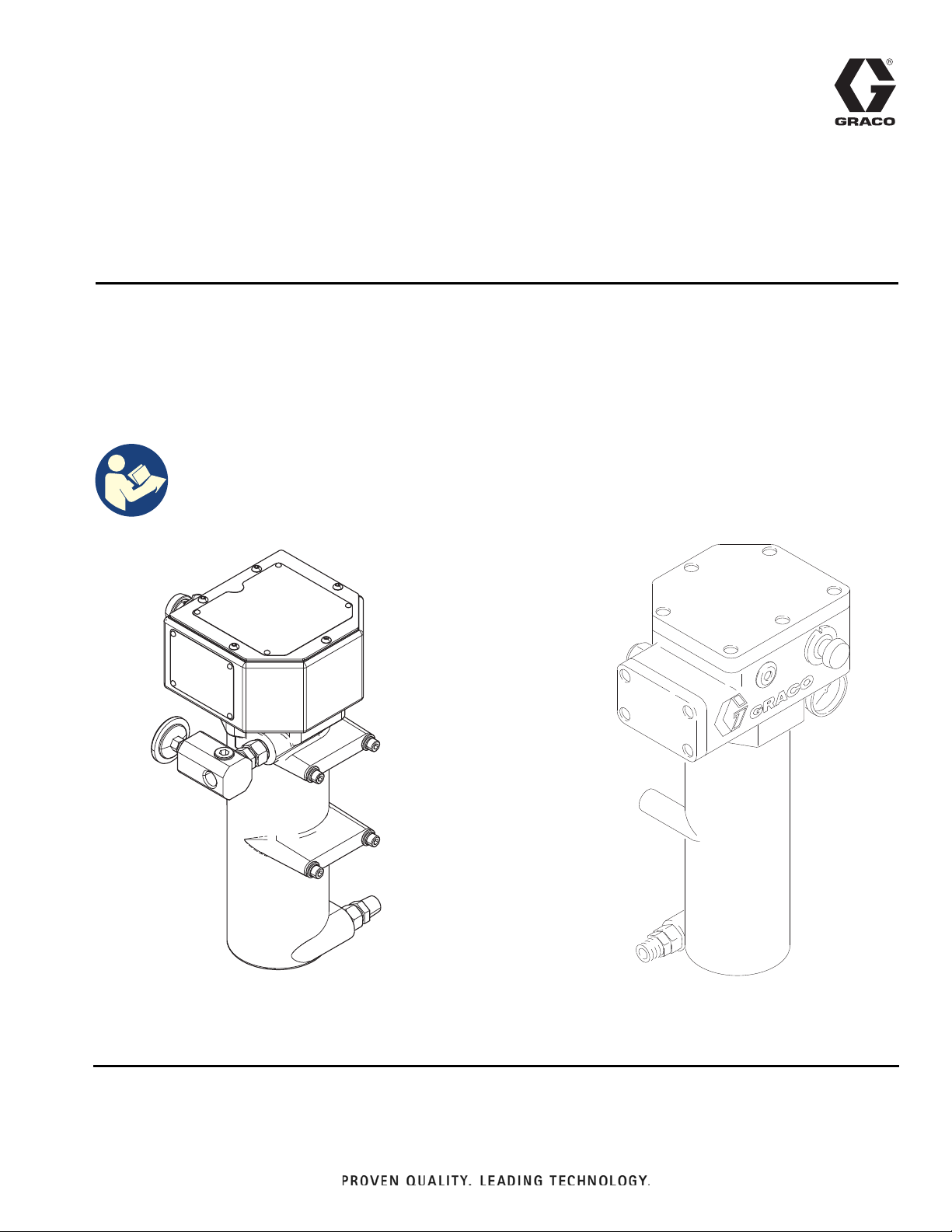
VISCON
High Pressure Fluid Heater
For variable heating of fluids. For professional use only.
7250 psi (50 MPa, 500 bar) Maximum Working Pressure
See page 2 for model information, including maximum working pressure and approvals.
Important Safety Instructions
Read all warnings and instructions in this
manual. Save these instructions.
HP
309524Z
EN
WLD
Non-Hazardous Location Heater
ti12338A
Hazardous Location Heater
Page 2

Contents
Models . . . . . . . . . . . . . . . . . . . . . . . . . . . . . . . . . . . 3
Hazardous Location Heaters . . . . . . . . . . . . . . . 3
Non-Hazardous Location Heaters . . . . . . . . . . . . 3
Warnings . . . . . . . . . . . . . . . . . . . . . . . . . . . . . . . . . 4
Installation . . . . . . . . . . . . . . . . . . . . . . . . . . . . . . . . 7
Typical Installation . . . . . . . . . . . . . . . . . . . . . . . 7
Component Identification . . . . . . . . . . . . . . . . . . . . 8
General Information . . . . . . . . . . . . . . . . . . . . . . 9
Selecting Tubing . . . . . . . . . . . . . . . . . . . . . . . . . 9
Mounting Heater . . . . . . . . . . . . . . . . . . . . . . . . 10
Fluid Connections & Accessories . . . . . . . . . . . 12
Electrical Connections . . . . . . . . . . . . . . . . . . . 13
Grounding . . . . . . . . . . . . . . . . . . . . . . . . . . . . . 13
Hazardous Area Cabling and Conduit
Requirements . . . . . . . . . . . . . . . . . . . . . . . 13
Operation . . . . . . . . . . . . . . . . . . . . . . . . . . . . . . . . 15
Pressure Relief Procedure . . . . . . . . . . . . . . . . 15
Initial Flushing . . . . . . . . . . . . . . . . . . . . . . . . . . 15
Priming System . . . . . . . . . . . . . . . . . . . . . . . . . 15
Setting Heater Control . . . . . . . . . . . . . . . . . . . 16
Adjusting for Spraying . . . . . . . . . . . . . . . . . . . . 16
Maintenance . . . . . . . . . . . . . . . . . . . . . . . . . . . . . . 17
Flushing . . . . . . . . . . . . . . . . . . . . . . . . . . . . . . . 17
Draining Heater . . . . . . . . . . . . . . . . . . . . . . . . . 17
Unclogging Fluid Passages . . . . . . . . . . . . . . . . 17
Troubleshooting . . . . . . . . . . . . . . . . . . . . . . . . . . . 18
Repair . . . . . . . . . . . . . . . . . . . . . . . . . . . . . . . . . . . 19
Primary Thermostat & Probe . . . . . . . . . . . . . . . 19
Backup Thermostat . . . . . . . . . . . . . . . . . . . . . . 19
Thermal Limit Sensor . . . . . . . . . . . . . . . . . . . . 21
Control Knob . . . . . . . . . . . . . . . . . . . . . . . . . . . 21
Heater Block . . . . . . . . . . . . . . . . . . . . . . . . . . . 21
Parts . . . . . . . . . . . . . . . . . . . . . . . . . . . . . . . . . . . . 23
Hazardous Location Heaters . . . . . . . . . . . . . . . 23
Non-Hazardous Location Heaters . . . . . . . . . . . 25
Accessories . . . . . . . . . . . . . . . . . . . . . . . . . . . . . . 27
Technical Specifications . . . . . . . . . . . . . . . . . . . . 28
Dimensions . . . . . . . . . . . . . . . . . . . . . . . . . . . . . . . 29
Hazardous Location Heater . . . . . . . . . . . . . . . . 29
Non-Hazardous Location Heater . . . . . . . . . . . . 29
California Proposition 65 . . . . . . . . . . . . . . . . . . . 29
Graco Standard Warranty . . . . . . . . . . . . . . . . . . . 30
Graco Information . . . . . . . . . . . . . . . . . . . . . . . . . 30
2 309524Z
Page 3
Models
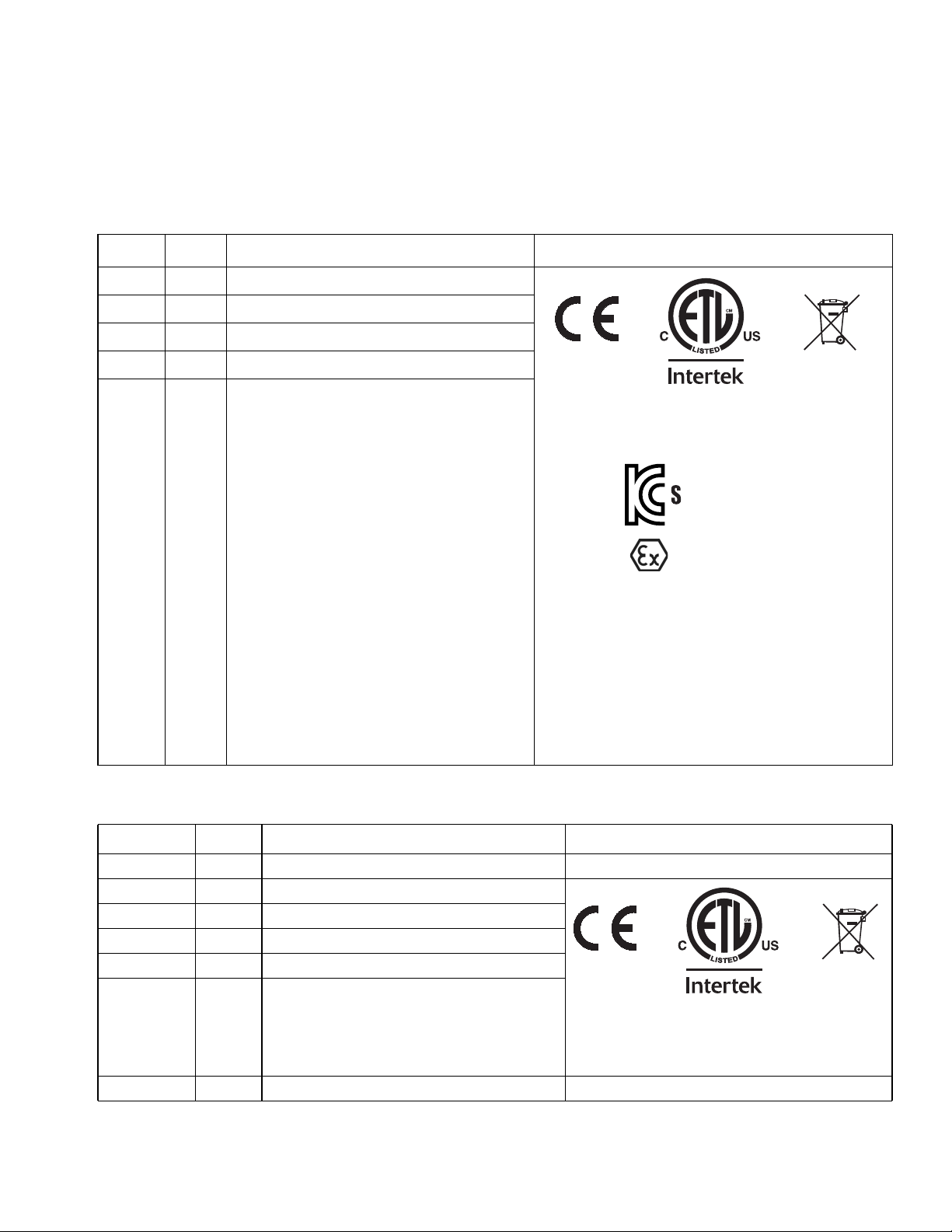
Hazardous Location Heaters
See Special Conditions for Safe Use in Warnings, page 4.
Models
Part Series VAC (50/60 Hz single phase) / Watts / Amps
245848 C 120 / 2300 / 19.2
245863 C 240 / 4000 / 16.7
245864 C 480 / 4000 / 8.30
245862 C 200 / 4000 / 20.0
246254 C 380 / 4000 /10.5
Approvals
Certified to CAN/CSA C22.2 No. 88
ATEX Ratings:
ATEX Certificate No. ITS14ATEX18155X
IECEx Ratings Ex db llB T4 Gb
IECEx Certificate No. IECEx ETL 14.0046X
Ta = -20°C to 60°C
For US/CAN:
Class 1, Division 1, Groups C, D (T3)
Ta = -20°C to 60°C
9902471
Conforms to
UL 499
18-KA4B0-0072X
II 2 G Ex db llB T4 Gb
See Technical Specifications, page 28, for additional
information.
Non-Hazardous Location Heaters
Model Series VAC (50/60 Hz single phase) / Watts / Amps
26A698 A 120 / 1800 / 15
245867 C 120 / 2300 / 19.2
245868 C 200 / 4000 / 20.0
245869 C 240 / 4000 / 16.7
245870 C 480 / 4000 / 8.30
246276 C 380 / 4000 / 10.5
Certified to CAN/CSA C22.2 No. 88
24J787* C 240 / 4000 / 16.7
* Only for use with Graco NVH systems. Must be controlled by GCA.
309524Z 3
Approvals
9902471
Conforms to
UL 499
Page 4
Warnings
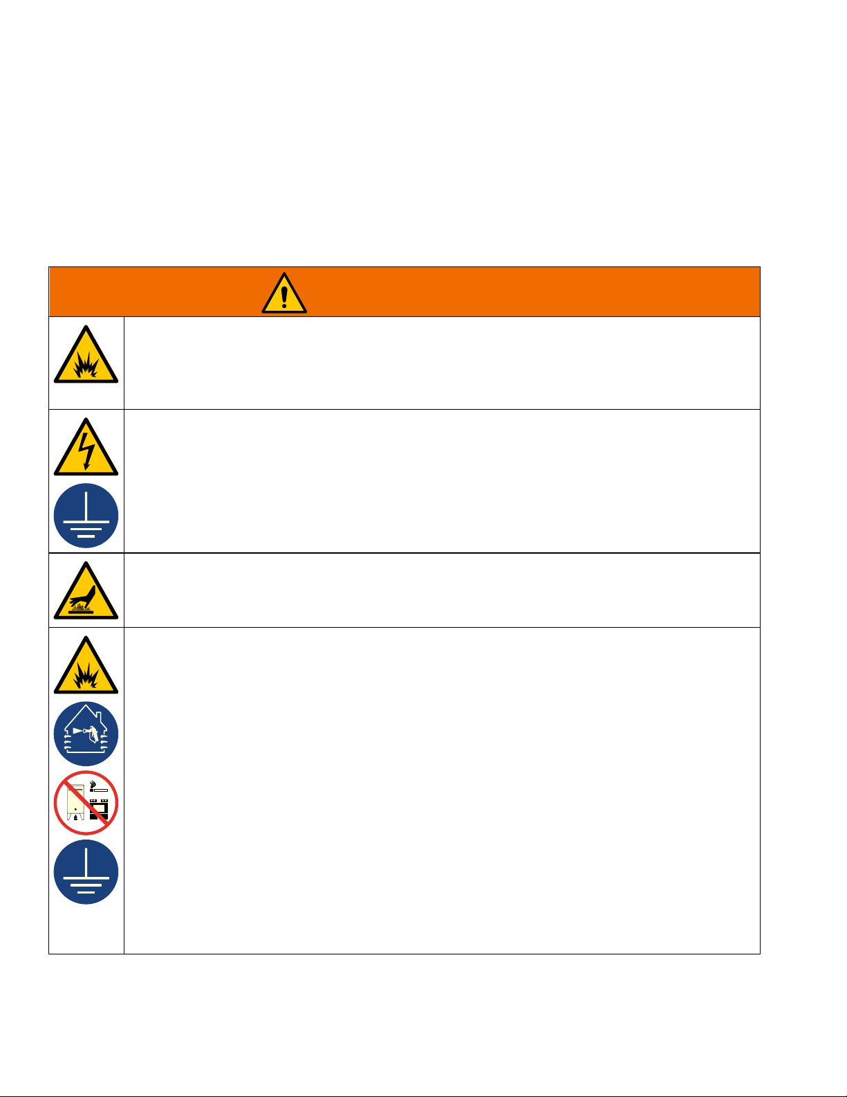
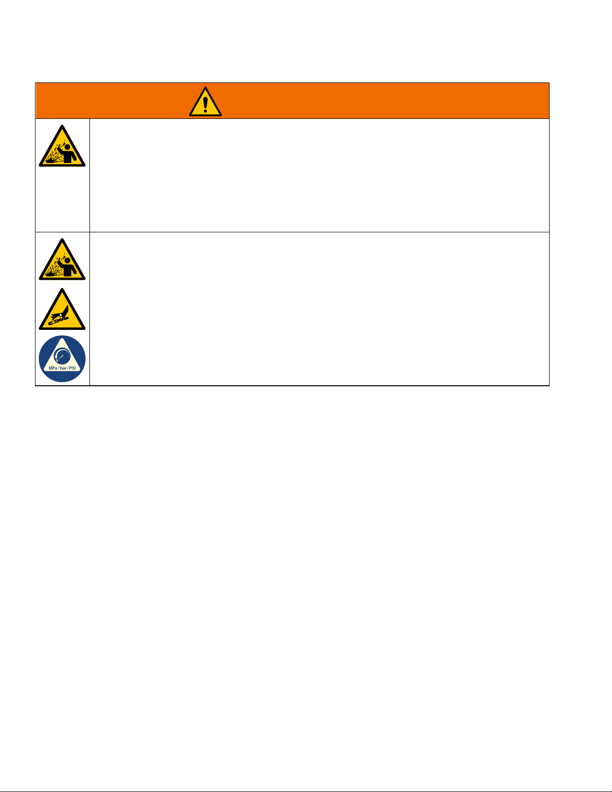
Warnings
The following warnings are for the setup, use, grounding, maintenance, and repair of this equipment. The
exclamation point symbol alerts you to a general warning and the hazard symbols refer to procedure-specific risks.
When these symbols appear in the body of this manual or on warning labels, refer back to these Warnings.
Product-specific hazard symbols and warnings not covered in this section may appear throughout the body of this
manual where applicable.
WARNING
SPECIAL CONDITIONS FOR SAFE USE
• For information on the required dimensions of the flameproof joints contact the holder of this
certificate (Graco Inc); Flamepath joints are not intended to be repaired.
• Special fasteners for securing equipment covers shall have a minimum yield strength of 1,100 MPa
and be corrosion resistant and sized M8 x 1.25 x 30.
ELECTRIC SHOCK HAZARD
This equipment must be grounded. Improper grounding, setup, or usage of the system can cause
electric shock.
• Turn off and disconnect power at main switch before disconnecting any cables and before servicing
or installing equipment.
• Connect only to grounded power source.
• All electrical wiring must be done by a qualified electrician and comply with all local codes and
regulations.
BURN HAZARD
Equipment surfaces and fluid that is heated can become very hot during operation. To avoid severe
burns:
• Do not touch hot fluid or equipment.
FIRE AND EXPLOSION HAZARD
Flammable fumes, such as solvent and paint fumes, in work area can ignite or explode. Paint or solvent
flowing through the equipment can cause static sparking. To help prevent fire and explosion:
• Use equipment only in well-ventilated area.
• Eliminate all ignition sources; such as pilot lights, cigarettes, portable electric lamps, and plastic drop
cloths (potential static sparking).
• Ground all equipment in the work area. See Grounding instructions.
• Never spray or flush solvent at high pressure.
• Keep work area free of debris, including solvent, rags and gasoline.
• Do not plug or unplug power cords, or turn power or light switches on or off when flammable fumes
are present.
• Use only grounded hoses.
• Hold gun firmly to side of grounded pail when triggering into pail. Do not use pail liners unless they
are anti-static or conductive.
• Stop operation immediately if static sparking occurs or you feel a shock. Do not use equipment until
you identify and correct the problem.
• Keep a working fire extinguisher in the work area.
• Never operate with covers removed. Do not open when energized.
• Install conduit within 18 in (457 mm).
• Do not install if operating temperature exceeds ignition temperature of hazardous atmosphere.
4 309524Z
Page 5
Warnings
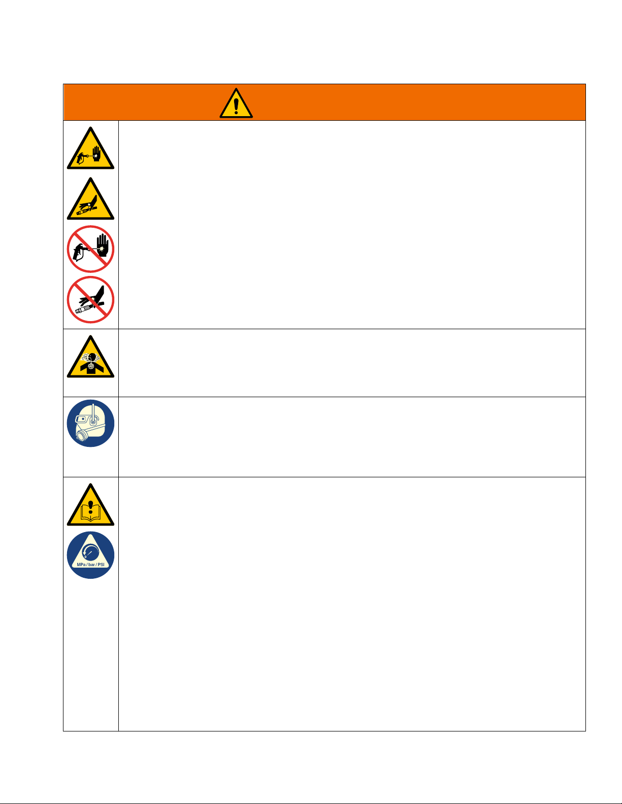
WARNING
SKIN INJECTION HAZARD
High-pressure fluid from gun, hose leaks, or ruptured components will pierce skin. This may look like
just a cut, but it is a serious injury that can result in amputation. Get immediate surgical treatment.
• Do not spray without tip guard and trigger guard installed.
• Engage trigger lock when not spraying.
• Do not point gun at anyone or at any part of the body.
• Do not put your hand over the spray tip.
• Do not stop or deflect leaks with your hand, body, glove, or rag.
• Follow the Pressure Relief Procedure when you stop spraying and before cleaning, checking, or
servicing equipment.
• Tighten all fluid connections before operating the equipment.
• Check hoses and couplings daily. Replace worn or damaged parts immediately.
TOXIC FLUID OR FUMES HAZARD
Toxic fluids or fumes can cause serious injury or death if splashed in the eyes or on skin, inhaled, or
swallowed.
• Read Safety Data Sheets (SDSs) to know the specific hazards of the fluids you are using.
• Store hazardous fluid in approved containers, and dispose of it according to applicable guidelines.
PERSONAL PROTECTIVE EQUIPMENT
Wear appropriate protective equipment when in the work area to help prevent serious injury, including
eye injury, hearing loss, inhalation of toxic fumes, and burns. Protective equipment includes but is not
limited to:
• Protective eyewear, and hearing protection.
• Respirators, protective clothing, and gloves as recommended by the fluid and solvent manufacturer.
EQUIPMENT MISUSE HAZARD
Misuse can cause death or serious injury.
• Do not operate the unit when fatigued or under the influence of drugs or alcohol.
• Do not exceed the maximum working pressure or temperature rating of the lowest rated system
component. See Technical Specifications in all equipment manuals.
• Use fluids and solvents that are compatible with equipment wetted parts. See Technical
Specifications in all equipment manuals. Read fluid and solvent manufacturer’s warnings. For
complete information about your material, request Safety Data Sheets (SDSs) from distributor or
retailer.
• Do not leave the work area while equipment is energized or under pressure.
• Turn off all equipment and follow the Pressure Relief Procedure when equipment is not in use.
• Check equipment daily. Repair or replace worn or damaged parts immediately with genuine
manufacturer’s replacement parts only.
• Do not alter or modify equipment. Alterations or modifications may void agency approvals and create
safety hazards.
• Make sure all equipment is rated and approved for the environment in which you are using it.
• Use equipment only for its intended purpose. Call your distributor for information.
• Route hoses and cables away from traffic areas, sharp edges, moving parts, and hot surfaces.
• Do not kink or over bend hoses or use hoses to pull equipment.
• Keep children and animals away from work area.
• Comply with all applicable safety regulations.
309524Z 5
Page 6
Warnings
WARNING
PRESSURIZED ALUMINUM PARTS HAZARD
Use of fluids that are incompatible with aluminum in pressurized equipment can cause serious chemical
reaction and equipment rupture. Failure to follow this warning can result in death, serious injury, or
property damage.
• Do not use 1,1,1-trichloroethane, methylene chloride, other halogenated hydrocarbon solvents or
fluids containing such solvents.
• Do not use chlorine bleach.
• Many other fluids may contain chemicals that can react with aluminum. Contact your material supplier
for compatibility.
THERMAL EXPANSION HAZARD
Fluids subjected to heat in confined spaces, including hoses, can create a rapid rise in pressure due to
the thermal expansion. Over-pressurization can result in equipment rupture and serious injury.
• Open a valve to relieve the fluid expansion during heating.
• Replace hoses proactively at regular intervals based on your operating conditions.
6 309524Z
Page 7
Installation
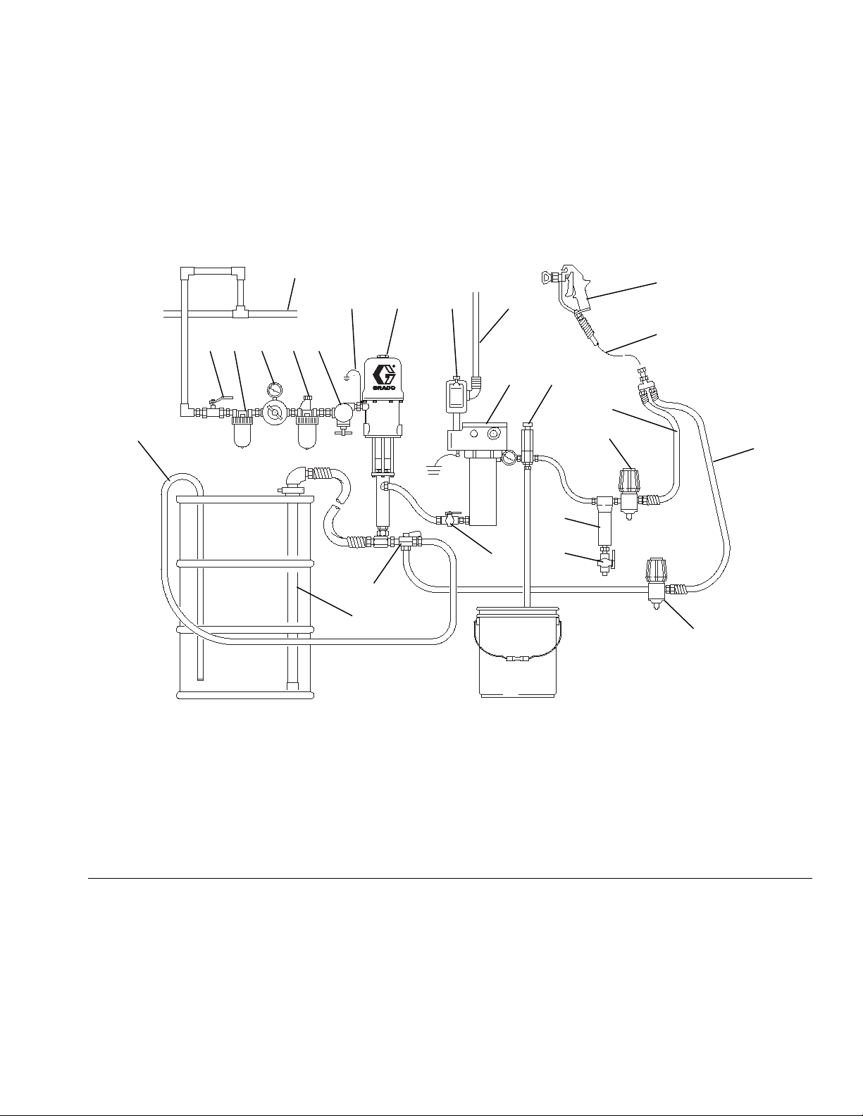
Typical Installation
FIG. 1 is only a guide. Your Graco distributor can assist in designing your system.
Installation
Z
HGF
J
Q
Y
EDCBA
XK
P
V
N
R
L
M
T
U
W
S
05486-524
Key:
A Bleed-type Master Air Valve
B Air Filter
C Air Regulator and Gauge
D Air Line Lubricator
E Pump Runaway Valve
F Ground Wire
G Pump
H Explosion Proof Power Switch
J Power Cable
K Heater
L Fluid Filter
M Drain Valve
N Fluid Pressure Regulator
P Fluid Supply Line
Q Spray Gun
R Fluid Return Line
S Back Pressure Valve
T Fluid Shutoff Valve
U Director Valve
V Drain Back Tube
W Suction Tube
X Pressure Relief Valve
Y Whip End Hose
Z Air Supply Line
FIG. 1: Typical Installation – Heated Circulating System
309524Z 7
Page 8
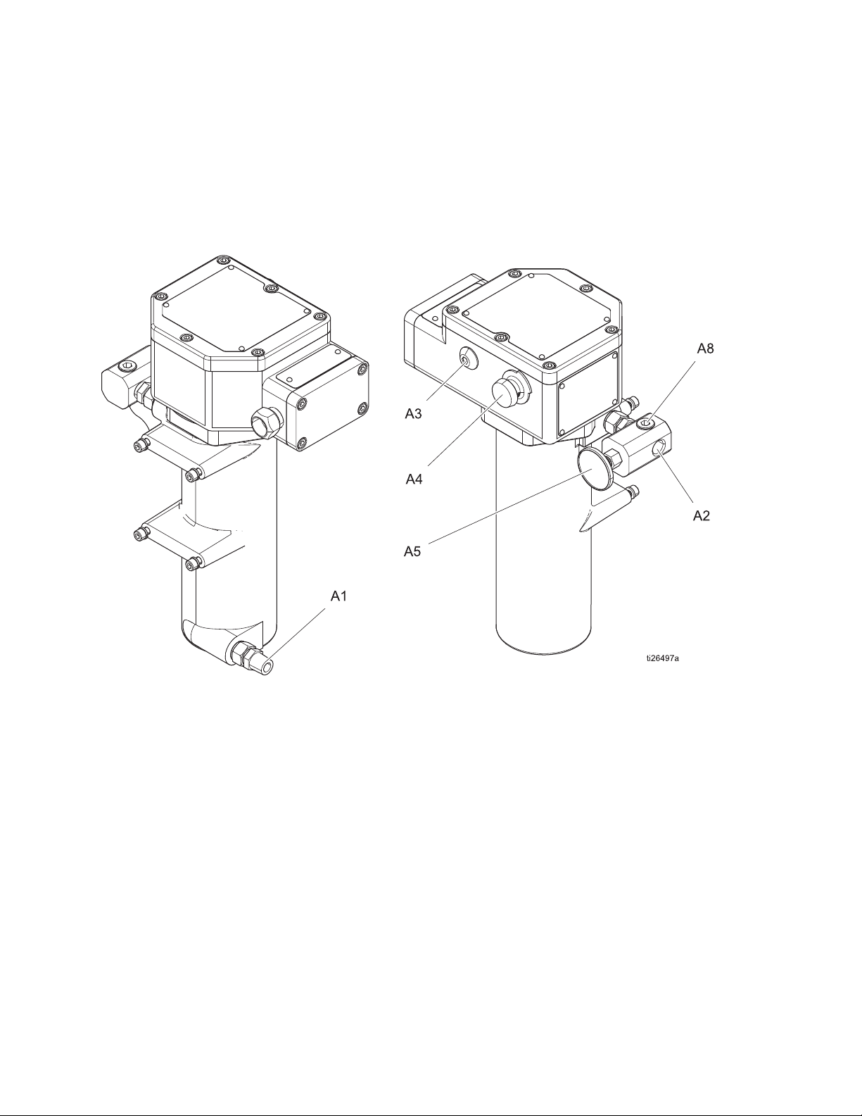
Component Identification
Component Identification
Key:
A1 Fluid Inlet
A2 Fluid Outlet
A3 Heater ON Indicator Light
A4 Temperature Control Knob
8 309524Z
A5 Temperature Gauge
A8 Optional Outlet Ports (one on outlet manifold and one on
opposite side of heater)
Page 9
General Information Selecting Tubing
Fluid loses some heat through the tubing or hose
between the heater and spray gun. Locate heater close
to the spray area to minimize heat loss through
• Select system components that meet
temperature and pressure ratings listed in
Technical Specifications, page 28. The
heater’s normal output range is adjustable from
84-220°F (29-104°C).
• To prevent fire and explosion, locate heater away
from all flammable materials and where
operators will not come in contact with hot metal
surfaces.
• To avoid burns, insulate and/or label lines and
components exiting heater that may become hot.
NOTICE
The inlet fluid temperature cannot exceed 275°F
(135°C). This will cause the heater to exceed its rated
temperature code.
plumbing.
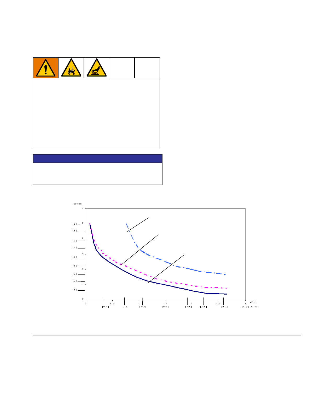
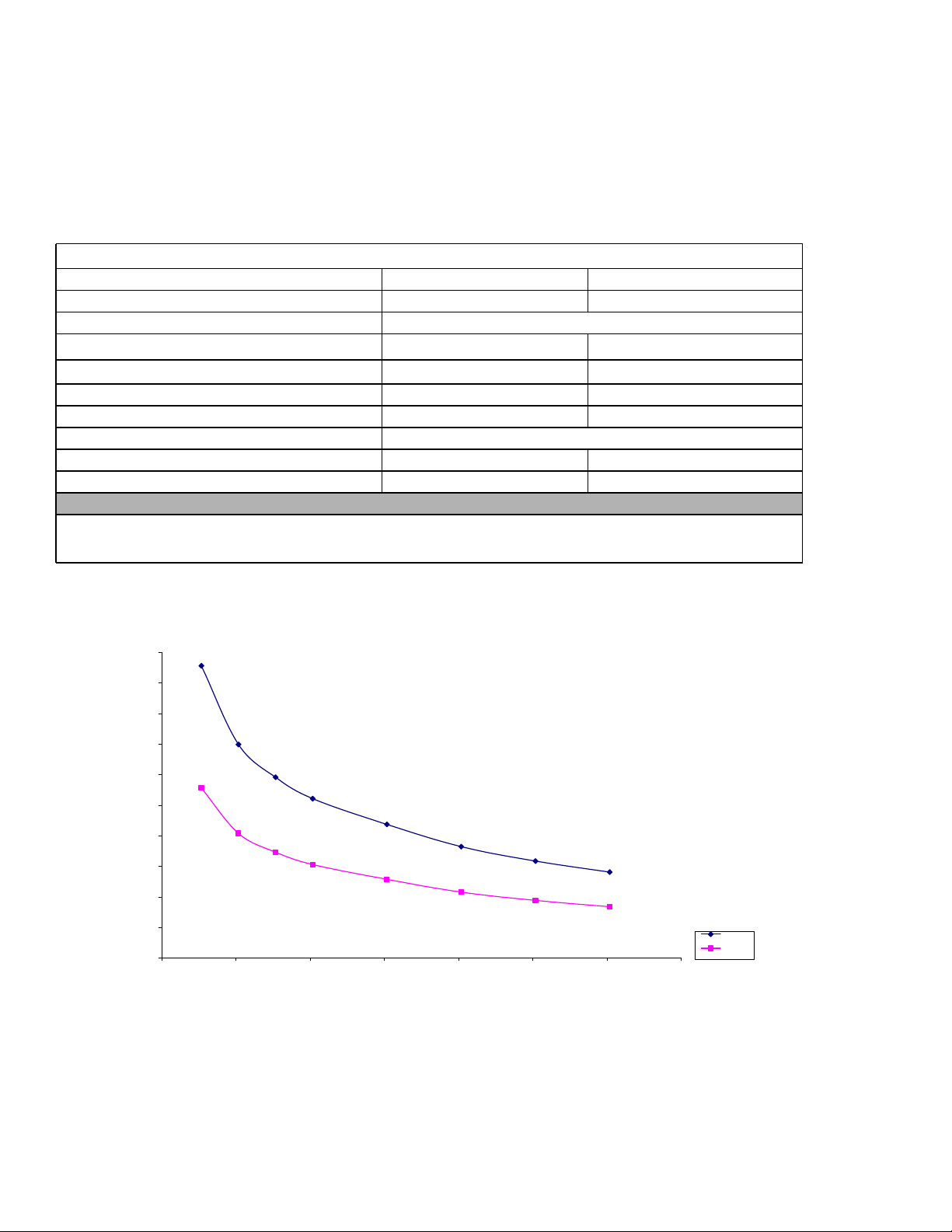
The chart in FIG. 2 shows a heat loss curve for 3
common types of tubing.
Chart Notes:
• Higher flow rates have less heat loss.
• Foam-insulated steel tubing and high pressure
airless paint hose retain heat best. Insulated tubing
and hose are more expensive, but higher costs are
commonly offset by lower operating costs.
• Locate heater close to spray area to minimize heat
loss through plumbing.
Component Identification
Typical Fluid Temperature Drop
FIG. 2: Typical Temperature Drop
Heat Loss Curve - 70° F (21° C) ambient
(20 ft.) 6.1 m steel tube
Fluid: (130° F) 54° C
(20 ft.) 6.1 m steel tube
(3/8 in.) 9 mm foam insulation
Fluid: (110° F) 43° C
(20 ft.) 6.1 m airless paint hose
Fluid: (110° F) 43° C
Flow Rate
309524Z 9
Page 10
Component Identification
Mounting Heater
Heater controls must be easily accessible.
The mounting surface must be able to support the
weight of the heater and fluid, and any stress caused
during operation.
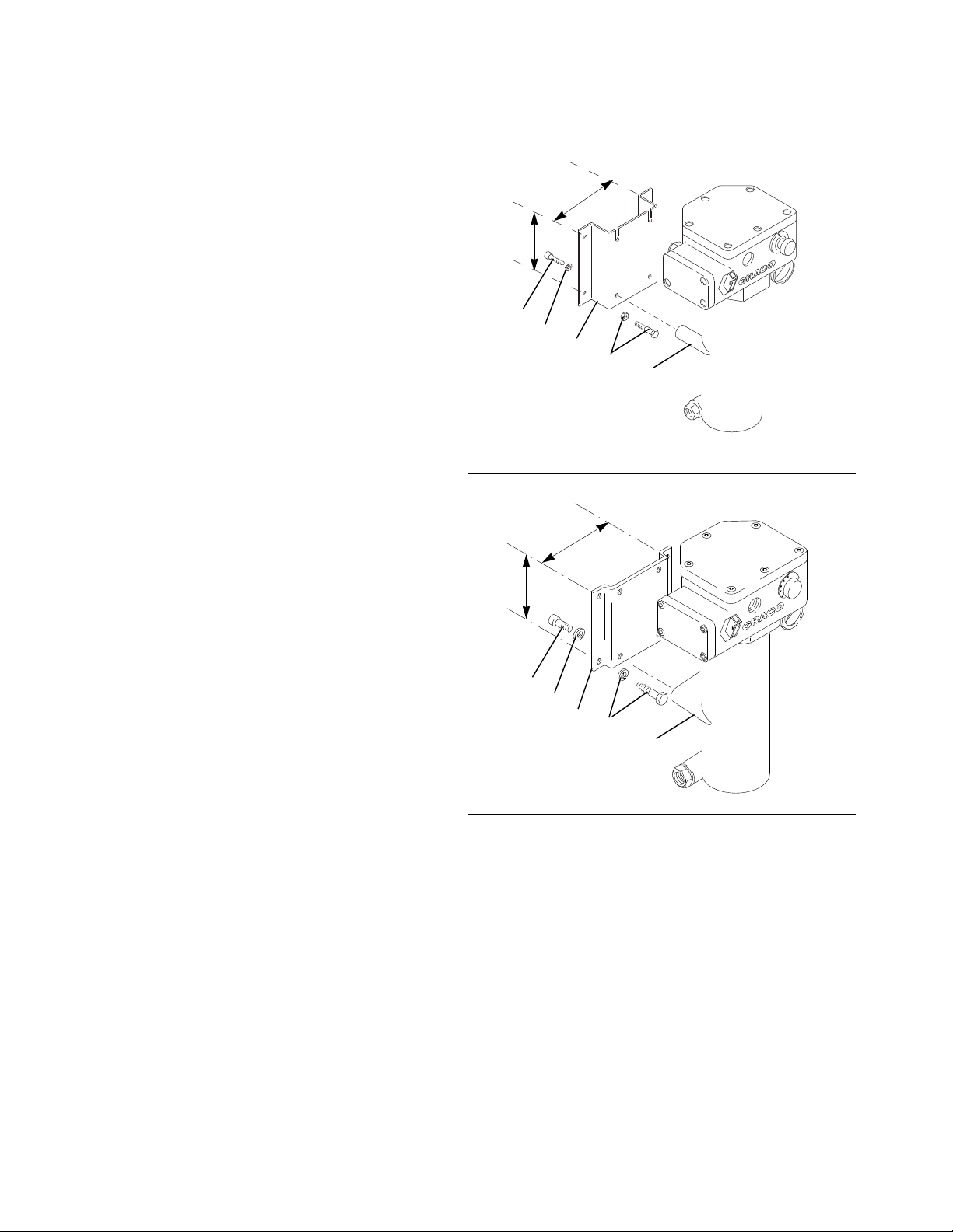
Wall Mounting
Requires wall bracket 192585 or 183982. See
Accessories, page 27. Use wall bracket as a template
to mark bolt holes.
Bracket 192585
(FIG. 3)
Bracket depth provides required solid object clearance
to comply with European flame proof standards.
1. Use M8 bolts of appropriate length and lockwasher
(CC), not supplied, to mount bracket.
2. Install two screws (6) and washers (5) into top 2
heater mounting posts (BB) until they are about 1/8
in. (3 mm) from fully installed.
6 in.
152.4 mm
5 in.
127 mm
6
5
YY
CC
FIG. 3: Bracket 192585
6 in.
152.4 mm
5 in.
127 mm
BB
05442
3. Lift heater and slide two screw heads into bracket
slots. Install remaining 2 screws and tighten all 4.
Bracket 183982
(FIG. 4)
1. Mount bracket (MM) to heater with screws (6) and
lockwashers (5) supplied.
2. Use M8 bolts of the appropriate length and
lockwasher (NN), not supplied, to secure the
bracket to the wall.
6
5
MM
NN
FIG. 4: Bracket 183982
PP
8631A
10 309524Z
Page 11

Component Identification
Cart Mounting
(FIG. 5)
Requires two each of cart mounting bar 183485 and
clamp 183484. See Accessories, page 27, to order.
1. Place clamps (AA) around the cart vertical post
(DD) and secure to the heater mounting bars (ZZ)
with M8 x 1.25 x 30 mm bolts (6) and lockwasher
(5).
2. Observe temperature ratings for the power cable to
the terminal junction. Cable H07RN does not meet
the required 221°F (105°C). An intermediate Type
“e” junction may be required. Also see FIG. 9.
DD
6
XP and XP-hf Mounting
Bracket Mounted Hose Heater
See Accessories, page 27, for hazardous and
non-hazardous location heaters.
WLD
5
AA
ZZ
FIG. 5: Cart Mounting
FIG. 6: XP and XP-hf Mounting
05543-524
WLD
FIG. 7: Mounted Hose Heater
309524Z 11
Page 12
Component Identification
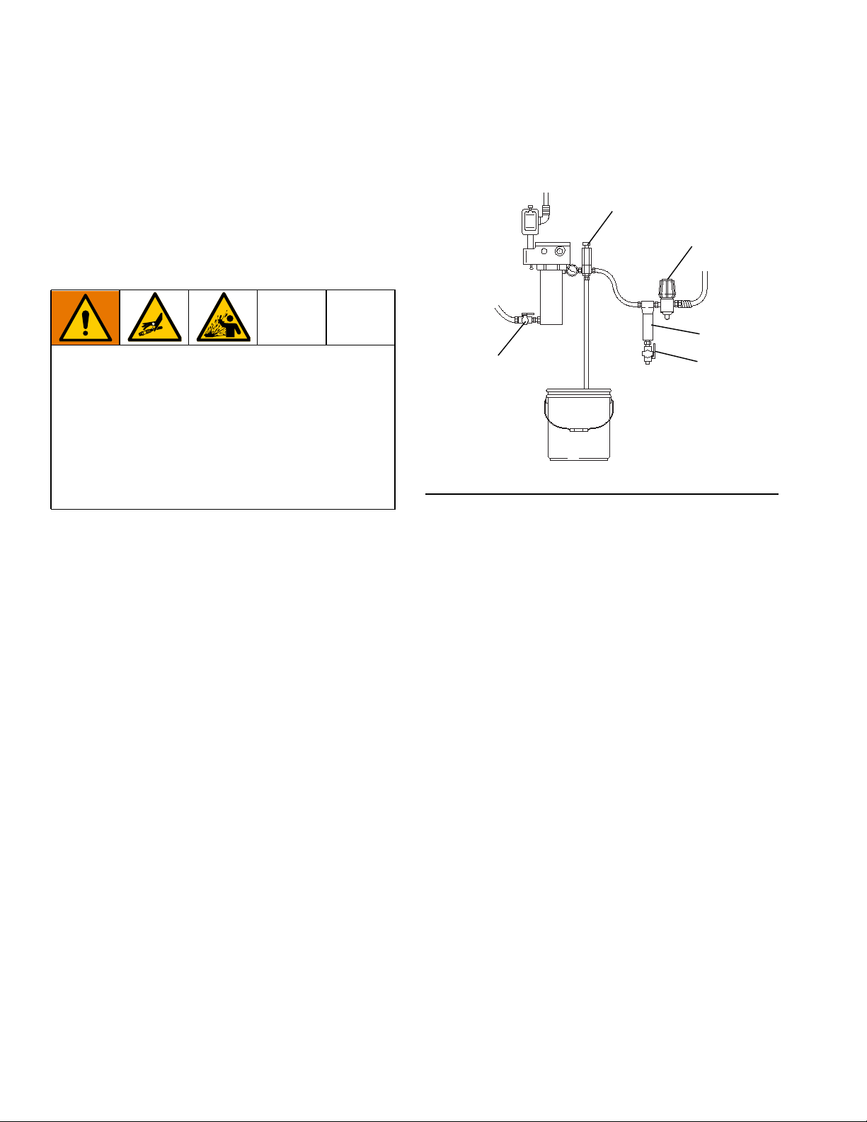
Fluid Connections & Accessories
(FIG. 8)
1. Install a fluid shutoff valve (T) in the heater’s 1/2-14
npt(m) fluid inlet; do not overtighten. Connect the
fluid line to the valve.
To prevent serious injury caused by component or
equipment rupture:
• Never install a shutoff device between the heater
and gun as this will trap the heated fluid and not
allow for expansion.
• Never use a fluid regulator as a shutoff device if it
is installed between the heater and gun
• Provide a means for adequately handling fluid
expansion caused by heat.
2. Provide a means for adequately handling fluid
expansion caused by heat. Options include:
3. Install a fluid filter (L), drain valve (M), and fluid
pressure regulator (N) near the heater’s 1/2-14
npt(f) fluid outlet. Then connect the fluid line.
X
N
L
T
FIG. 8: Fluid Connections & Accessories
M
05545-524
- Use flexible hoses between heater and gun.
- Install a properly sized accumulator
downstream from the heater.
- Install a pressure relief valve (X) pre-set to
relieve pressure when it exceeds the system
maximum working pressure.
12 309524Z
Page 13
Component Identification
Electrical Connections
Heater installation must be in compliance with all
applicable local codes and regulations. This
equipment must be grounded. Improper grounding,
setup, or usage of the system can cause electric
shock. All electrical wiring must be done by a qualified
electrician and comply with all local codes and
regulations.
NOTICE
To help prevent damage, avoid spilling liquids onto
electrical components and never operate with the
cover removed or screws missing.
Requirements For All Installations
• The power supply must not exceed heater voltage
and amperage. See Contents, page 2.
Grounding
The equipment must be grounded to reduce the risk
of static sparking and electric shock. Electric or static
sparking can cause fumes to ignite or explode.
Improper grounding can cause electric shock.
Grounding provides an escape wire for the electric
current.
Wire the heater to a properly grounded power supply
through the electrical connections and grounding
screw (8). In a mobile installation, also ground the truck
or trailer to a true earth ground.
Hazardous Area Cabling and Conduit Requirements
• Conductors used for supply connection must be
suitable for at least 221°F (105°C). An intermediate
Type “e” junction may be required.
• Branch circuit breaker over-current protection must
be used. See chart below for recommended branch
circuit breaker by amp rating.
Rating by VAC/Watts/Amperes Circuit breaker size
120 VAC/2300 W/19.2 A 30 A
200 VAC/4000 W/20.0 A 30 A
240 VAC/4000 W/16.7 A 25 A
380 VAC/4000 W/10.5 A 25 A
480 VAC/4000 W/8.3 A 25 A
• For non-hazardous location heaters, connections
are made through a strain relief cord grip. Cord grip
121603 will accept cords with an outside diameter of
0.51-0.71 in. (13-18 mm).
• Make your ground connection to the green ground
lug inside the control head.
Explosion Proof
All electrical wiring in the hazardous area must be
encased in Class I, Division I, Groups C1 and D
approved explosion-proof conduit. Follow all National,
State, and Local electric codes.
A conduit seal (D) is required within 18 in. (457 mm) of
the heater for the US and Canada. All cables must be
rated at 221°F (105°C).
Flame Proof (ATEX)
Use appropriate conduit, connectors, and cable glands
rated for ATEX II 2 G. Follow all national, state, and
local electric codes. All cable glands and cables must be
rated at 221°F (105°C).
See Power Cord Set for more information on cables for
hazardous locations.
• For hazardous models only: Make your power
connections through the 3/4 npt port to the two post
bushings in the control head. Refer to Hazardous
Area Cabling and Conduit Requirements.
309524Z 13
Page 14

Component Identification
Wall Mounted Wiring
Mount a 2-pole, explosion-proof electric switch (H) near
the heater. See FIG. 9. The switch must meet the
electrical codes for your location. Use the correct cable
and plug.
+
1
Power terminal
2
Neutral terminal or 2nd
power terminal
WLD
3
Ground terminal
4
Tighten all terminal nuts to
30 in-lb (3.4 N•m)
Cart Mounted Wiring
Connect a plug that meets the electrical codes for your
location. See FIG. 10.
1
Power terminal
2
Neutral terminal or 2nd
power terminal
FIG. 10: Cart Mounted Wiring
WLD
3
Ground terminal
4
Tighten all terminal nuts to
30 in-lb (3.4 N•m)
05547-524
FIG. 9: Wall Mounted Wiring
05546-524
14 309524Z
Page 15

Operation
Operation
Pressure Relief Procedure
Follow the Pressure Relief Procedure whenever
you see this symbol.
This equipment stays pressurized until pressure is
manually relieved. To help prevent serious injury from
pressurized fluid, such as skin injection, and
splashing fluid, follow the Pressure Relief Procedure
when you stop spraying and before cleaning,
checking, or servicing the equipment.
1. Engage the gun safety lock.
2. Shut off main power to the heater.
3. Circulate fluid for at least 10 minutes to cool the
heated fluid and heater.
4. Shut off all air and fluid supplies.
5. Disengage the safety lock.
Initial Flushing
To avoid fire and explosion:
• Flush equipment only in a well-ventilated area
• Ensure main power is off and heater is cool before
flushing
• Do not turn on heater until fluid lines are clear of
solvent
The heater was tested with lightweight oil, which needs
to be flushed out before using the equipment. Ensure
main power is off and heater is cool before flushing. Use
a compatible solvent, and follow flushing instructions in
your fluid supply and spray gun manual.
Priming System
(Refer to FIG. 1, page 7)
NOTICE
6. Hold a metal part of the gun firmly to a grounded
metal pail, and trigger the gun to relieve pressure.
7. Engage the safety lock.
8. Have a container ready to catch the fluid, then open
the fluid drain valve.
To prevent damage, do not turn on heater until system
is fully primed.
1. Do not turn on the heater yet.
2. If using an airless spray gun, do not install a spray
tip yet.
3. Start the pump according to the instructions
supplied with it.
4. Turn the system director valve (U) to circulate, and
circulate fluid for several minutes.
5. Open the spray gun (Q) at the last outlet to prime
the line. Repeat for all gun stations.
6. Engage the gun safety latch.
7. Shut off the air supply to the pump.
8. Follow Pressure Relief Procedure.
9. Install the gun spray tip.
309524Z 15
Page 16
Operation
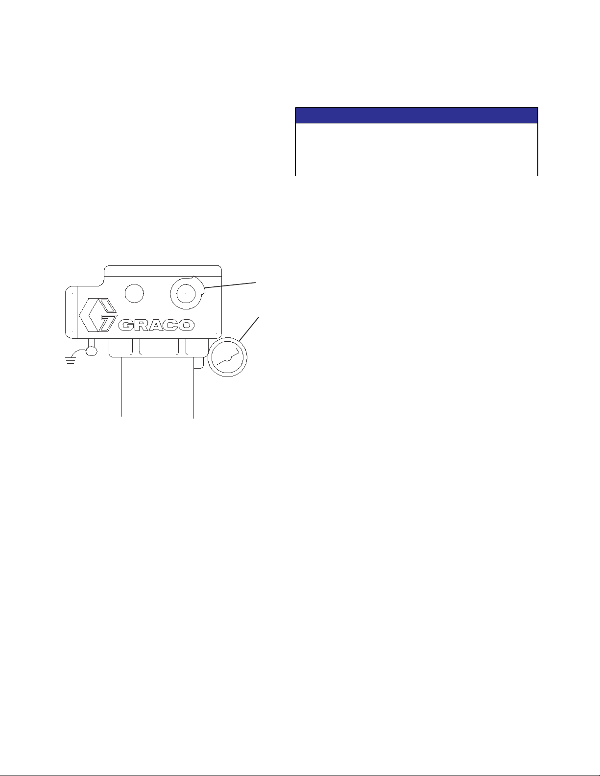
Setting Heater Control
(Refer to FIG. 11)
1. Set the heater control knob (33) to a trial setpoint of
4 or 5.
2. Start the pump and circulate fluid through the
system at very low pressure, about 10-12 oz/min
(0.30-0.35 liter/min).
3. After 10 minutes, read the temperature on the
thermometer (2). If it does not match the desired
temperature, adjust the setpoint.
33
2
Adjusting for Spraying
NOTICE
Operating the heater at its highest setting of over
180°F (82°C) for long periods of time decreases the
heater life and can cause fluid to dry out which can
cause heater clogging and a poor spray pattern.
1. Adjust pump pressure and heater setpoint to the
lowest settings needed for good fluid atomization
2. Set all system back pressure valves (S - FIG. 1) to
maintain even fluid pressure at all gun stations.
FIG. 11: Setting Heater Control
05549-524
16 309524Z
Page 17

Maintenance
Maintenance
Flushing
To avoid fire and explosion:
• Flush equipment only in a well-ventilated area
• Ensure main power is off and heater is cool before
flushing
• Do not turn on heater until fluid lines are clear of
solvent
Clogged fluid passages are difficult to clean and reduce
heating efficiency, flow rate, and pressure. Flush
frequently, including whenever system is not in use.
1. Follow Pressure Relief Procedure, page 15.
2. Ensure main power is off and heater is cool before
flushing. Use a compatible solvent, and follow
flushing instructions in your fluid supply and spray
gun manual. Do not turn on heater until fluid
lines are clear of solvent.
Unclogging Fluid Passages
(FIG. 13)
1. Drain the heater.
2. Remove the heater block (3) from the heater
housing. See Heater Block, page 21.
3. Pour a high strength, compatible solvent into the
heater tube to soften the clog.
4. Flush out the clog.
5. Clean all passages thoroughly before reassembling.
Pour in solvent
Draining Heater
(FIG. 12)
1. Follow Pressure Relief Procedure, page 15.
2. Remove heater inlet and outlet fittings. Have a
container ready to catch the fluid.
Outlet
Inlet
05550-524
FIG. 12: Draining Heater
3
05551-524
FIG. 13: Unclogging Fluid Passages
309524Z 17
Page 18

Troubleshooting
Troubleshooting
Problem Cause Solution
Heater will not heat. No current. Check circuit and fuses.
Check continuity of primary
thermostat (24), backup thermostat
(10), and thermal limit sensor (15).
Check continuity of thermostat (10)
and heater block (3) terminals - Page
19.
Burned out heater block (3). Replace block - Page 21.
Blown heat limiter (15). Check continuity of primary
thermostat (24) and backup
thermostat (10). Replace thermostats
if necessary when replacing thermal
limit sensor (15) - Pages 19-21.
Temperature too low. Fluid requires more warm-up time. Increase warm-up time.
Wrong temperature setting. Adjust setting - Page 16.
Flow rate too high. Reduce flow rate or use 2 heaters.
Clogged fluid passages. Flush regularly - Page 17.
Temperature too high. Wrong temperature setting. Adjust setting - Page 16.
Failed primary thermostat (24). Replace - Page 19.
High fluctuating temperatures, about
220-250°F (104-120°C) at 0.1 GPM.
Too much pressure drop or fluid will
not flow.
Heater fittings leak. Loose or damaged fittings. Tighten fittings or replace heater
Primary thermostat (24) contacts
sticking.
Replace thermostats (24, 10) - Page
19. Note that backup thermostat (10)
keeps heater functioning for only a
short time.
Flow rate too high. Reduce flow rate or use 2 heaters.
Clogged fluid passages. Flush regularly - Page 17.
block - Page 21.
10
WHITE
11
BLACK
3
BLOCK, HEATER
WHITE
BLACK
53
J3 = 120 VAC
J2 = 200/240 VAC
J1 = 380/480 VAC
ti31122a
L1
GND
L2
37
BLACK
BLACK
37
WHITE
24
15
FIG. 14: Electrical Schematic
18 309524Z
Page 19
Repair
To avoid burns, electric shock, and skin injection,
make sure the main power is OFF, heater is cool, and
pressure is relieved before repairing.
Hazardous Location Heaters: See FIG. 15 & 17
Non-hazardous Location Heaters: See FIG. 16 & 18
Repair
NOTICE
To avoid damaging capillary tube (GG), which can
cause heater malfunction, do not kink or nick the
tube.
To avoid shorting out the heater, do not allow
capillary tube to contact the block terminal (3a).
Follow step 10, below.
10. Liberally apply thermal lubricant (part no. 110009) to
probe (EE) of new thermostat (24). Loop capillary
tube (GG) several times and wrap the loops with tie
strap (42-not shown). Insert probe in the heater
block (3).
Primary Thermostat & Probe
1. Follow Pressure Relief Procedure, page 15.
2. Remove housing cover (18).
3. Hazardous Location Heater only: Loosen nut
(27a).
Non-hazardous Location Heater only: Loosen
screws (25).
4. Loosen setscrew (26) in switch shaft (28).
5. Remove screw (16) and bracket (19) holding probe
(EE).
6. Remove wires from the primary thermostat
terminals (FF).
7. Pull thermostat probe (EE) out of heater block (3).
Remove thermostat (24) from housing (1).
8. Hazardous Location Heater only: Remove screws
(25).
Non-hazardous Location Heater only: Remove
screw standoff (35) with washer (27b).
11. Continue reassembling in reverse order of
disassembly. See Reassembly Notes, below.
Backup Thermostat
1. Follow Pressure Relief Procedure, page 15.
2. Remove housing cover (18).
3. Remove screws (HH) on backup thermostat (10)
tabs, and remove the wires – one from heater block
(3a) and one from line in (9b).
4. Remove the two screws (16), then remove the
thermostat (10).
5. Liberally apply thermal lubricant (part no. 110009) to
the bottom of the thermostat (10) and reinstall it in
reverse order of disassembly.
Reassembly Notes
• Refer to FIG. 15 or 16 for wiring connections.
• Non-hazardous Location Heater only: Make sure
gasket (47) is installed and aligned with electrical
housing screw holes.
9. Remove bracket from thermostat (24) and secure to
new thermostat.
309524Z 19
• Secure cover (18) with lockwashers (5) and screws
(6 or 52); torque screws to 89 in-lb (10 N•m).
Page 20

Repair
++
E
D
/
D
19
16
/
HH
*1'
1
Apply thermal lubricant
2
Torque to 89 in-lb (10 N•m)
E
WLE
Wiring Diagram
1
10
16
ti2335e
15
EE
1
FIG. 15: Thermostat Repair – Hazardous Location Heaters
3a
FF
GG
24
6
18
27a
5
52
2
25
35
1
26
28
GND
3b
HH
10
L1
19
3a
15
9b
9a
L2
Wiring Diagram
ti30862a
HH
1
Apply thermal lubricant
2
Torque to 89 in-lb (10 N•m)
FIG. 16: Thermostat Repair – Non-hazardous Heaters
16
19
15
1
ti2337e
10
16
52
2
18
47
GG
FF
24
26
28
27b
35
1
25
1
EE
3a
20 309524Z
Page 21

Repair
Thermal Limit Sensor
NOTICE
To avoid damaging the capillary tube (GG), which can
cause heater malfunction, do not kink or nick the
tube.
To avoid shorting out the heater, do not allow the
capillary tube to contact the block terminal (3a).
1. Follow Pressure Relief Procedure, page 15.
2. Remove housing cover (18).
3. Remove nut (FF) and nut (3b) holding the leads of
the thermal limit sensor (15) and remove the sensor.
See FIG. 15 or 16, page 20.
4. Apply thin film of thermal lubricant (part no. 110009)
to the thermal limit sensor (15) bulb and install a
new sensor in the reverse order of disassembly.
See Reassembly Notes.
Control Knob
1. Follow Pressure Relief Procedure, page 15.
Heater Block
1. Follow Pressure Relief Procedure, page 15.
2. Remove housing cover (18).
3. Hazardous Location Heater only: Remove
electrical junction box cover (4).
4. Hazardous Location Heater only: In the junction
box (1b), disconnect the main power lead from the
terminal of the post bushing (9a).
Non-hazardous Location Heater only: Disconnect
the main power lead from the primary thermostat
(24).
5. Hazardous Location Heater only: In the electrical
housing (1a), use a wrench on the flats of the post
bushing (9a) to unscrew it from the housing.
6. See the appropriate sections on pages 19-21 to
remove the primary thermostat and probe (24), the
backup thermostat (10), the thermal limit sensor
(15) and the control knob (33).
7. Remove the 6 screws (6) and lockwashers (5)
holding the housing to the heater block (3).
2. Turn knob (33) to setpoint 1.
3. Loosen setscrew (30) in the control knob (33).
4. Remove control knob (33).
5. Remove adjusting knob (12) from the control knob
(33), and press fit it onto the new control knob.
Check the bushing (29) and replace it if worn.
6. Position new knob (33) so setpoint 1 aligns with
mark (JJ) on the housing (12:00 position) and the
knob is about 1/16 in. (1 mm) away from the
housing. Tighten setscrew (30).
8. Reassemble heater with the new block (3) in
reverse order of disassembly.
Reassembly Notes
• Refer to FIG. 15 or 16 for wiring connections.
• Non-hazardous Location Heater only: Make sure
gasket (47) is installed and aligned with electrical
housing screw holes.
• Secure cover (18) with lockwashers (5) and screws
(6 or 52); torque screws to 89 in-lb (10 N•m).
309524Z 21
Page 22

Repair
1
Torque to 89 in-lb (10 N•m)
2
Electrical Housing
3
Junction Box
4
Apply sealant
10
15
24
18
1
6
5
JJ
29
30
33
12
2
1a
3
1b
4
5
6
1
FIG. 17: Control Repair – Hazardous Location Heaters
1
Torque to 89 in-lb (10 N•m)
2
Electrical Housing
3
Apply sealant
10
15
1
6
5
9a
4
4
3a
3b
3
1
52
ti2334g
18
47
24
JJ
29
30
33
12
1
2
1
9
5
7
3
3b
6
1
5
3a
3
ti2336h
FIG. 18: Control Repair – Non-hazardous Location Heaters
22 309524Z
Page 23
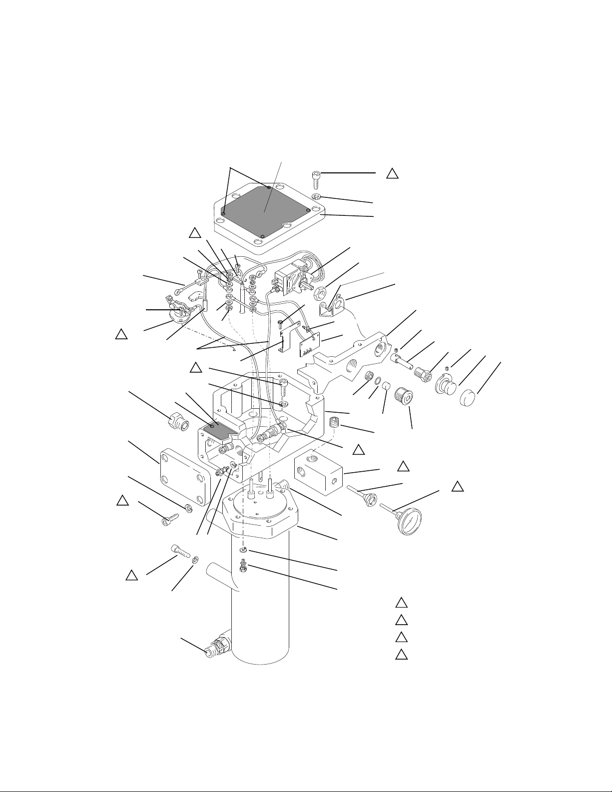
Parts
Hazardous Location Heaters
Parts
3
47
5
1
14
43
6
1
5
18
4
62
11
63
65
19
16
24
27a
25
35
16
10
15
14
4
36
37
63
62
52
53
55
6
1
5
51
50
1
48
58
9
2
32
54
2
56
20
1
26
28
30
29
2
33
12
2
6
31
8
7
1
6
5
31
ti2334g
309524Z 23
3
7
8
1
Torque to 89 in-lb (10 N•m)
2
Apply sealant
3
Apply thermal lubricant
4
Torque nuts (62) to 13-14 in-lb (1.4-1.5 N•m)
Page 24

Parts
Hazardous Location Heaters
Ref. No. 3
Heater Block
Part Series
245848 C 246616 120 / 2300
245862 C 246617 200 / 4000
245863 C 246618 240 / 4000
245864 C 246619 480 / 4000
246254 C 246620 380 / 4000
Ref. Part Description Qty.
1 183074 CONTROL HOUSING 1
2 102124 THERMOMETER DIAL 1
3 HEATER BLOCK; see table;
includes ref. no. 2, 31, 32, 56
4 183066 COVER 1
5 107542 LOCKWASHER 20
6 109114 SCREW; M8 x 1.25 mm 20
7 111307 WASHER; lock ext. 2
8 116343 GROUNDING CLAMP 2
9 108675 BUSHING; 1000 V max.; 250 A
max.
10 108674 BACKUP THERMOSTAT 1
11 235524 WIRE ASSEMBLY 1
12 177969 KNOB 1
14 100055 SCREW; #6 type U 10
15 223126 THERMAL LIMIT SENSOR, 152° 1
16 105676 SCREW; M4 x 0.7 x 12 mm 4
18 183073 COVER 1
19 183072 BRACKET 2
20 17D130 LIGHT HOUSING 1
21 108664 ALLEN WRENCH; 6 mm 1
Part Volts / Watts
Ref. Part Description Qty.
22 105747 ALLEN WRENCH; 2 mm 1
23 101369 ALLEN WRENCH; 0.0927 in. 1
24 108676 PRIMARY THERMOSTAT 1
25 100032 SCREW; #6-32 UNC-2A 2
26 105672 SET SCREW; M4 x 0.7 x 6 mm 1
27a 183070 NUT; M15 x 1.5 1
28 183068 SWITCH SHAFT 1
29 183071 BUSHING; M15 x 1.5 1
30 101366 SET SCREW; #10-24 x 0.312 in. 1
31 117344 FITTING; 5/8 in. OD tube x 1/2-14
npt(m)
32 15A808 T-FITTING 1
1
33 177968 KNOB 1
35 183067 BRACKET 1
36 15B623 WARNING PLATE, English 1
15B777 WARNING PLATES, multilingual 1
37 246346 WIRE ASSEMBLY 2
42 102478 TIE STRAP 1
2
43 15B625 WARNING PLATE. English 1
15B819 WARNING PLATE, multilingual 1
47 185065 ADAPTER, 3/4 npt 1
48 15B827 LIGHT LENS 1
50 103338 O-RING; fluoroelastomer 1
51 117483 SOCKET JAM SCREW;
52 117514 SPACER 2
53 246014 LIGHT CIRCUIT BOARD 1
54 114669 SCREW; M5 x 10 mm 2
55 15B243 BRACKET 1
56 15D757 HOUSING, thermometer 1
58 100361 PLUG, pipe; 1/2 npt 1
62 100166 NUT, full hex 4
63 513505 WASHER, flat 4
65 112906 WASHER, lock, spring 2
5/8-18 x 5/16
2
1
Replacement Danger and Warning labels, tags and
cards are available at no cost.
24 309524Z
Page 25

Non-Hazardous Location Heaters
Parts
14
43
52
18
47
16
62
4
65
63
11
16
63
3
10
15
62
37
25
19
53
54
24
26
28
27b
35
25
29
30
33
12
8
64
14
36
51
50
48
20
1
1
9
5
58
32
2
7
56
2
2
1
6
5
3
31
1
Torque to 89 in-lb (10 N•m)
2
Apply sealant
ti2336h
3
Apply thermal lubricant
4
Torque nuts (62) to 13-14 in-lb (1.4-1.5 N•m)
309524Z 25
Page 26

Parts
Non-Hazardous Location Heaters
Ref. No. 3
Heater Block
Part Series
26A698 A 17X893 120 / 1800
245867 C 246616 120 / 2300
245868 C 246617 200 / 4000
245869 C 246618 240 / 4000
245870 C 246619 480 / 4000
246276 C 246620 380 / 4000
24J787 C 15A886 240 / 4000
Ref. Part Description Qty.
1 262891 ENCLOSURE 1
2* 102124 THERMOMETER DIAL 1
3 HEATER BLOCK; see table;
includes ref. no. 2, 31, 32, 56
5 107542 LOCKWASHER 1
6 109114 SCREW 6
7 15A990 GASKET 2
8* 116343 GROUND CLAMP 2
9 117367 SCREW; M8 x 18 mm 6
10 108674 THERMOSTAT 1
11 235524 WIRE ASSEMBLY 1
12* 177969 KNOB 1
14 100055 SCREW; #6 type U 10
15* 223126 THERMAL LIMIT SENSOR; 152° 1
16 105676 SCREW; M4 x 0.7 x 12 mm 4
18 15A810 TOP COVER 1
19* 183072 BRACKET 2
20 15B828 LIGHT HOUSING 1
21* 108664 ALLEN WRENCH; 6 mm 1
22* 105747 ALLEN WRENCH; 2 mm 1
Part Volts / Watts
Ref. Part Description Qty.
23* 101369 ALLEN WRENCH; 0.0927 in. 1
24* 108676 THERMOSTAT SWITCH 1
25* 100032 SCREW; #6-32 UNC-2A 4
26* 105672 SET SCREW 1
27b* 114027 WASHER; #6 2
28* 183068 SWITCH SHAFT 1
29* 112738 GROMMET 2
30* 101366 SET SCREW; #10-24 x 0.312 in. 1
31 117344 FITTING; 5/8 in. OD tube x 1/2-14
npt(m)
32* 15A808 T-FITTING 1
33* 177968 KNOB 1
35* 117526 SPACER 2
36 15B623 WARNING PLATE; English 1
1
15B777 WARNING PLATES; multilingual 1
37* 246346 WIRE ASSEMBLY 2
42* 102478 TIE STRAP 1
43 15B625 WARNING PLATE; English 1
15B819 WARNING PLATE; multilingual 1
47 15A991 GASKET 1
48 15B827 LIGHT LENS 1
50 103338 O-RING; fluoroelastomer 1
51 117483 SOCKET JAM SCREW;
5/8-18 x 5/16
52 111962 SCREW; 1/4-28 UNRF-3a 5
53* 246014 LIGHT CIRCUIT BOARD 1
54 106216 NUT; 3/4-14 npsm 1
55* 100633 ALLEN WRENCH; 5/32 1
56* 15D757 HOUSING; thermometer 1
58* 100361 PLUG, pipe; 1/2 npt 1
62 100166 NUT; full hex 4
63 513505 WASHER; flat 4
64 111307 WASHER; lock ext.
65 112906 WASHER; lock, spring 2
2
1
Replacement Danger and Warning labels, tags and
cards are available at no cost.
* Parts not used in 24J787.
26 309524Z
Page 27

Accessories
Accessories
Heater Conversion Kit
246302: Includes two fittings to make VISCON HP ports
match VISCON
2
Mounting Bracket
192585: European version (see below)
M8
AB
D
C
E
F
Cart Bracket
Order two each of the following:
183484: Clamp
183485: Mounting bar
6
5
183484
183485
5 & 6 included with heater
Power Cord Set
For Non-Hazardous Locations:
05543
Measurements – inches (mm)
ABCDEF
5
(127)
6.76
(171.7)
0.88
(22.4)
3.37
(85.5)
6.25
(158.8)
1.44
(36.6)
183982: US / CAN version
GH
6
(152)
5
(127)
G
H
110160*: 600 V, 12 Awg, Extra Hard Usage Type St,
High Temperature (221°F, 105°C) rated
For Hazardous Locations (flameproof):
24W679: 600 V, 12 Awg, Extra Hard Usage Type St,
High Temperature (221°F, 105°C) rated
*Hazardous location heaters are no longer rated for use
in a hazardous area when used with these accessories.
Thermal Lubricant
110009: 6.5 gram tube
Hose Heater (bracket mounted)
For parts, refer to your XP and XP-hf proportioner
manual.
273095: Non-hazardous locations
273094: Hazardous locations
309524Z 27
Page 28
Technical Specifications
Technical Specifications
The heater can be used in the following environmental conditions: indoor use, 99% maximum relative humidity,
pollution degree 2, installation category II, maximum ambient temperature 140° F (60° C).
Viscon HP High Pressure Fluid Heater
US Metric
Maximum Working Pressure 7250 psi 50 MPa, 500 bar
Voltage / Wattage / Current* See Contents, page 2
Fluid Passage Area
Fluid Passage Diameter
182 in
0.435 in
2
117,419 mm
11.1 mm
Fluid Passage Length 133 in 3383 mm
Thermometer Range 64–250°F 18–121°C
Wetted Parts Stainless Steel
Temperature Operating Range 84–219°F 29–104°C
Weight 39 lb 17.6 kg
Notes
* Main supply fluctuation not to exceed 10%
All trademarks or registered trademarks are the property of their respective owners.
2
100
90
80
70
60
50
40
30
Maximum Temperature Rise (°F)
20
10
0
00.511.522.533.5
94.16
54.14
4000 watt VISCON HP heater, Test Fluid: 10w Hydraulic Oil
2300 watt VISCON HP heater, Test Fluid: 10w Hydraulic Oil
NOTE: Line shows continuous operation of 1 heater.
Use additional heaters if necessary.
68.39
57.70
50.68
39.32
33.18
29.14
42.23
34.96
24.28
20.10
Flow Rate (GPM)
30.26
17
.40
26.64
15.32
Maximum Temperature Rise vs. Flow Rate
4000W
2300W
28 309524Z
Page 29

Dimensions
Dimensions
Hazardous Location Heater Non-Hazardous Location Heater
H
G
J
3/4 npt(f)
Electrical
Conduit Port
K
L
1/2 npt(f)
1/2 npt(m)
Fluid Outlet
Fluid Inlet
GHJKL
9.375 in.
(238
mm)
8.46 in.
(215
mm)
6.5 in.
(165
mm)
18 in.
(457
mm)
6.375 in.
(162
mm)
*
+
-
.
/
WLD
GHJKL
7.26 in.
(184
mm)
7.04 in.
(179
mm)
6.80 in.
(173
mm)
17.27 in.
(439
mm)
6.375 in.
(162
mm)
California Proposition 65
CALIFORNIA RESIDENTS
WARNING: Cancer and reproductive harm – www.P65warnings.ca.gov.
309524Z 29
Page 30

Graco Standard Warranty
Graco warrants all equipment referenced in this document which is manufactured by Graco and bearing its name to be free from defects in
material and workmanship on the date of sale to the original purchaser for use. With the exception of any special, extended, or limited warranty
published by Graco, Graco will, for a period of twelve months from the date of sale, repair or replace any part of the equipment determined by
Graco to be defective. This warranty applies only when the equipment is installed, operated and maintained in accordance with Graco’s written
recommendations.
This warranty does not cover, and Graco shall not be liable for general wear and tear, or any malfunction, damage or wear caused by faulty
installation, misapplication, abrasion, corrosion, inadequate or improper maintenance, negligence, accident, tampering, or substitution of
non-Graco component parts. Nor shall Graco be liable for malfunction, damage or wear caused by the incompatibility of Graco equipment with
structures, accessories, equipment or materials not supplied by Graco, or the improper design, manufacture, installation, operation or
maintenance of structures, accessories, equipment or materials not supplied by Graco.
This warranty is conditioned upon the prepaid return of the equipment claimed to be defective to an authorized Graco distributor for verification of
the claimed defect. If the claimed defect is verified, Graco will repair or replace free of charge any defective parts. The equipment will be returned
to the original purchaser transportation prepaid. If inspection of the equipment does not disclose any defect in material or workmanship, repairs
will be made at a reasonable charge, which charges may include the costs of parts, labor, and transportation.
THIS WARRANTY IS EXCLUSIVE, AND IS IN LIEU OF ANY OTHER WARRANTIES, EXPRESS OR IMPLIED, INCLUDING BUT NOT
LIMITED TO WARRANTY OF MERCHANTABILITY OR WARRANTY OF FITNESS FOR A PARTICULAR PURPOSE.
Graco’s sole obligation and buyer’s sole remedy for any breach of warranty shall be as set forth above. The buyer agrees that no other remedy
(including, but not limited to, incidental or consequential damages for lost profits, lost sales, injury to person or property, or any other incidental or
consequential loss) shall be available. Any action for breach of warranty must be brought within two (2) years of the date of sale.
GRACO MAKES NO WARRANTY, AND DISCLAIMS ALL IMPLIED WARRANTIES OF MERCHANTABILITY AND FITNESS FOR A
PARTICULAR PURPOSE, IN CONNECTION WITH ACCESSORIES, EQUIPMENT, MATERIALS OR COMPONENTS SOLD BUT NOT
MANUFACTURED BY GRACO. These items sold, but not manufactured by Graco (such as electric motors, switches, hose, etc.), are subject to
the warranty, if any, of their manufacturer. Graco will provide purchaser with reasonable assistance in making any claim for breach of these
warranties.
In no event will Graco be liable for indirect, incidental, special or consequential damages resulting from Graco supplying equipment hereunder, or
the furnishing, performance, or use of any products or other goods sold hereto, whether due to a breach of contract, breach of warranty, the
negligence of Graco, or otherwise.
FOR GRACO CANADA CUSTOMERS
The Parties acknowledge that they have required that the present document, as well as all documents, notices and legal proceedings entered into,
given or instituted pursuant hereto or relating directly or indirectly hereto, be drawn up in English. Les parties reconnaissent avoir convenu que la
rédaction du présente document sera en Anglais, ainsi que tous documents, avis et procédures judiciaires exécutés, donnés ou intentés, à la suite
de ou en rapport, directement ou indirectement, avec les procédures concernées.
Graco Information
For the latest information about Graco products, visit www.graco.com.
For patent information, see www.graco.com/patents.
TO PLACE AN ORDER, contact your Graco distributor or call to identify the nearest
distributor.
Phone: 612-623-6921 or Toll Free: 1-800-328-0211 Fax: 612-378-3505
All written and visual data contained in this document reflects the latest product information available at the time of publication.
GRACO INC. AND SUBSIDIARIES • P.O. BOX 1441 • MINNEAPOLIS MN 55440-1441 • USA
Copyright 2020, Graco Inc. All Graco manufacturing locations are registered to ISO 9001.
Graco reserves the right to make changes at any time without notice.
2ULJLQDOLQVWUXFWLRQV This manual contains English. MM 309524
International Offices: Belgium, China, Japan, Korea
Graco Headquarters: Minneapolis
www.graco.com
Revision
Z, September 2020
 Loading...