

Page 1
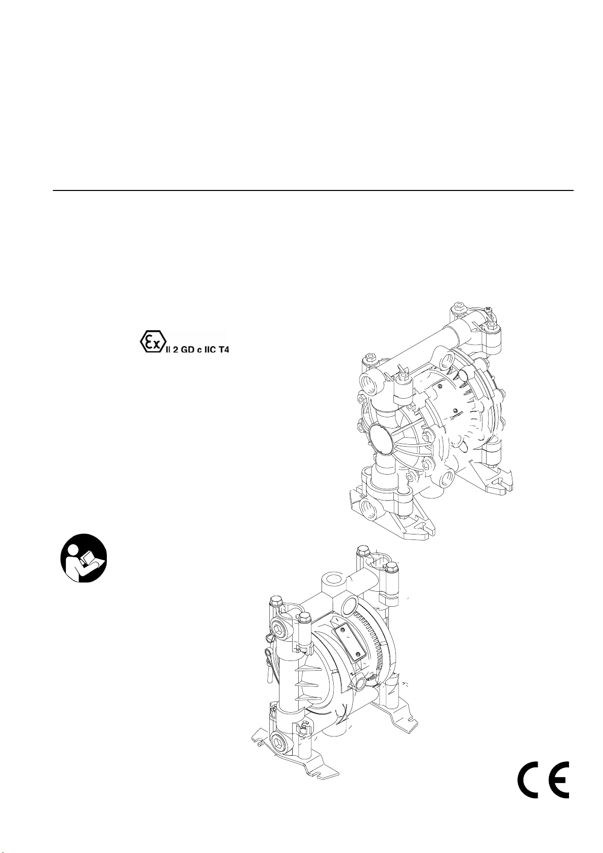
INSTRUCTIONS–PARTS LIST
Air-Operated
Diaphragm Pumps
For fluid transfer applications. For professional use only.
100 psi; 0.7 MPa; 7 bar Maximum Fluid Working Pressure
100 psi; 0.7 MPa; 7 bar Maximum Air Input Pressure
ALUMINUM AND STAINLESS STEEL*
These pumps a
*
M 60
*
Important Safety Instructions
Read all warnings and instructions in this manual.
Save these instructions.
re
cert
ified.
9065A
VERDERAIR VA 15
M 60
Page 2
Table of Contents
Symbols
Safety Warnings 2. . . . . . . . . . . . . . . . . . . . . . . . . . . . . . . . . . . . .
Installation 4. . . . . . . . . . . . . . . . . . . . . . . . . . . . . . . . . . . . . . . . . .
Operation 10. . . . . . . . . . . . . . . . . . . . . . . . . . . . . . . . . . . . . . . . .
Maintenance 11. . . . . . . . . . . . . . . . . . . . . . . . . . . . . . . . . . . . . . .
Troubleshooting 12. . . . . . . . . . . . . . . . . . . . . . . . . . . . . . . . . . . .
Service 13. . . . . . . . . . . . . . . . . . . . . . . . . . . . . . . . . . . . . . . . . . .
VERDERAIR VA 15 and VERDERAIR VA 20
Pump Listing 20. . . . . . . . . . . . . . . . . . . . . . . . . . . . . . . . . . . . . . .
VERDERAIR VA 15 and VERDERAIR VA 20
Repair Kits 23. . . . . . . . . . . . . . . . . . . . . . . . . . . . . . . . . . . . . . . .
Parts
VERDERAIR VA 15 and VERDERAIR VA 20
Common Parts 24. . . . . . . . . . . . . . . . . . . . . . . . . . . . . . . . . . .
VERDERAIR VA 15 Parts Drawing 25. . . . . . . . . . . . . . . . .
VERDERAIR VA 15 Fluid Section Parts List 26. . . . . . . . . .
VERDERAIR VA 20 Parts Drawing 28. . . . . . . . . . . . . . . . .
VERDERAIR VA 20 Fluid Section Parts List 29. . . . . . . . . .
Torque Sequence 30. . . . . . . . . . . . . . . . . . . . . . . . . . . . . . . . . . .
VERDERAIR VA 15:
Technical Data 31. . . . . . . . . . . . . . . . . . . . . . . . . . . . . . . . . . .
Dimensions 32. . . . . . . . . . . . . . . . . . . . . . . . . . . . . . . . . . . . .
VERDERAIR VA 20:
Technical Data 33. . . . . . . . . . . . . . . . . . . . . . . . . . . . . . . . . . .
Dimensions 34. . . . . . . . . . . . . . . . . . . . . . . . . . . . . . . . . . . . .
VERDERAIR VA 15 and VERDERAIR VA 20
Performance Charts 35. . . . . . . . . . . . . . . . . . . . . . . . . . . . . . . .
Customer Services/Guarantee 37. . . . . . . . . . . . . . . . . . . . . . . .
Warning Symbol
Warning
This symbol alerts you to the possibility of serious injury or
death if you do not follow the instructions.
Caution Symbol
Caution
This symbol alerts you to the possibility of damage to or destruction of equipment if you do not follow the instructions.
INSTRUCTIONS
Warning
EQUIPMENT MISUSE HAZARD
Equipment misuse can cause the equipment to rupture or malfunction and result in serious injury.
This equipment is for professional use only.
Read all instruction manuals, tags, and labels before operating the equipment.
Use the equipment only for its intended purpose. If you are not sure, call your VERDER distributor.
Do not alter or modify this equipment. Use only genuine VERDER parts and accessories.
Check equipment daily. Repair or replace worn or damaged parts immediately.
Do not exceed the maximum working pressure of the lowest rated component in your system. This equipment
has a 100 psi; 0.7 MPa (7 bar) maximum working pressure at 100 psi; 0.7 MPa (7 bar) maximum incoming air pressure.
Use fluids and solvents that are compatible with the equipment wetted parts. Refer to the Technical Data
section of all equipment manuals. Read the fluid and solvent manufacturer’s warnings.
Route hoses away from traffic areas, sharp edges, moving parts, and hot surfaces. Do not expose VERDER
hoses to temperatures above 180F (82C) or below –40C (–40C).
Wear hearing protection when operating this equipment.
Do not lift pressurized equipment.
Comply with all applicable local, state, and national fire, electrical, and safety regulations.
2 819.6900
Do not use 1.1.1-trichloroethane, methylene chloride, other halogenated hydrocarbon solvents or fluids
containing such solvents in pressurized aluminum equipment. Such use could result in a chemical reaction,
with the possibility of explosion.
Page 3
Warning
TOXIC FLUID HAZARD
Hazardous fluid or toxic fumes can cause serious injury or death if splashed in the eyes or on the skin, inhaled, or
swallowed.
Know the specific hazards of the fluid you are using.
Do not lift a pump under pressure. If dropped, the fluid section may rupture. Always follow the Pressure Relief
Procedure on page 10 before lifting the pump.
Store hazardous fluid in an approved container. Dispose of hazardous fluid according to all local, state, and
national guidelines.
Always wear protective eyewear, gloves, clothing, and respirator as recommended by the fluid and solvent
manufacturer.
Pipe and dispose of the exhaust air safely, away from people, animals, and food handling areas. If the
diaphragm fails, the fluid is exhausted along with the air. Read Air Exhaust Ventilation on page 6.
Never use an acetal pump to pump acids. Take precautions to avoid acid or acid fumes from contacting the
pump housing exterior. Stainless steel parts will be damaged by exposure to acid spills and fumes.
FIRE AND EXPLOSION HAZARD
Improper grounding, poor ventilation, open flames, or sparks can cause a hazardous condition and result in a fire
or explosion and serious injury.
Ground the equipment. Refer to Grounding on page 8.
Never use a non–conductive polypropylene or PVDF pump with non-conductive flammable fluids as specified
by your local fire protection code. Refer to Grounding on page 8 for additional information. Consult your fluid
supplier to determine the conductivity or resistivity of your fluid.
If there is any static sparking or you feel an electric shock while using this equipment, stop pumping
immediately. Do not use the equipment until you identify and correct the problem.
Provide fresh air ventilation to avoid the buildup of flammable fumes from solvents or the fluid being pumped.
Pipe and dispose of the exhaust air safely, away from all sources of ignition. If the diaphragm fails, the fluid is
exhausted along with the air. Read Air Exhaust Ventilation on page 6.
Keep the work area free of debris, including solvent, rags, and gasoline.
Electrically disconnect all equipment in the work area.
Extinguish all open flames or pilot lights in the work area.
Do not smoke in the work area.
Do not turn on or off any light switch in the work area while operating or if fumes are present.
Do not operate a gasoline engine in the work area.
819.6900 3
Page 4
Installation
General Information
The Typical Installations in Fig. 2 are only guides for
selecting and installing system components. Contact your
VERDER distributor for assistance in planning a system
to suit your needs.
Always use Genuine VERDER Parts and Accessories.
Use a compatible, liquid thread sealant on all male
threads. Tighten all connections firmly to avoid air or fluid
leaks.
Tightening Threaded Fasteners Before First
Use
Before using the pump for the first time, check and retorque
all external fasteners. See Torque Sequence, page 30. After
the first day of operation, retorque the fasteners. Although
pump use varies, a general guideline is to retorque fasteners
every two months.
Toxic Fluid Hazard
Caution
Safe Operating Temperatures
Minimum (all pumps): 40_ F (4_ C)
Maximum
Acetal: 180F (82 C)
Polypropylene: 150F (66 C)
Aluminum, stainless steel, PVDF: 225F (107 C)
These temperatures are based upon mechanical stress only
and may be significantly altered by pumping certain chemicals. Consult engineering guides for chemical compatibilities
and temperature limits, or contact your VERDER distributor.
Mountings
These pumps can be used in a variety of installations.
Be sure the mounting surface can support the weight of
the pump, hoses, and accessories, as well as the stress
caused during operation.
Read Toxic Fluid Hazard on
page 3.
Use fluids and solvents that are compatible with the equipment wetted parts. Refer to the Technical Data section of
all equipment manuals. Read the fluid and solvent
manufacturer’s warnings.
Fig. 2 shows some installation examples. On all installa-
tions, mount the pump using screws and nuts.
Pumping High-Density Fluids
High density fluids may prevent the lighter non-metallic check
valve balls from seating properly, which reduces pump performance significantly. Stainless steel balls should be used for
such applications.
4 819.6900
Page 5
Installation
Air Line
Warning
A bleed-type master air valve (B) is required in your system
to relieve air trapped between this valve and the pump.
See Fig. 2. Trapped air can cause the pump to cycle unexpectedly, which could result in serious injury, including
splashing in the eyes or on the skin, injury from moving
parts, or contamination from hazardous fluids.
Caution
The pump exhaust air may contain contaminants. Ventilate
to a remote area if the contaminants could affect your fluid
supply. Read Air Exhaust Ventilation on page 6.
1. Install the air line accessories as shown in Fig. 2. Mount
these accessories on the wall or on a bracket. Be sure
the air line supplying the accessories is electrically conductive.
a. The fluid pressure can be controlled in either of two
ways. To control it on the air side, install an air regulator (G). To control it on the fluid side, install a fluid
regulator (J) near the pump fluid outlet (see Fig. 2).
b. Locate one bleed-type master air valve (B) close
to the pump and use it to relieve trapped air. Read
the Warning above. Locate the other master air
valve (E) upstream from all air line accessories and
use it to isolate them during cleaning and repair.
c. The air line filter (F) removes harmful dirt and
moisture from the compressed air supply.
2. Install an electrically conductive, flexible air hose (C)
between the accessories and the 1/4 npt(f) pump air
inlet. Use a minimum 1/4 in. ID air hose. Screw an air
line quick disconnect coupler (D) onto the end of the air
hose (C), and screw the mating fitting into the pump air
inlet snugly. Do not connect the coupler (D) to the fitting
yet.
Installation of Remote Pilot Airlines
1. Connect the air line to the pump as noted above.
2. Connect 1/4 OD tubing to the push type connectors (16)
on the underside of the pump.
NOTE: By replacing the push type connectors, other sizes
or types of fittings may be used. The new fittings will
require 1/8 in. npt threads.
3.
onnect the other end of the tubes to the external air
C
signal, such as Cycleflo (PN 819.9742) or Cycleflo II
(819.9743) controllers.
NOTE: The air pressure at the connectors must be at least
30% of the air pressure to the air motor for the pump
to operate.
Fluid Suction Line
If using a conductive (acetal or polypropylene) pump, use
conductive hoses. If using a non-conductive pump,
ground the fluid system. Read Grounding on page 8.
The fluid inlet port is 1/2 in. or 3/4 in..
At inlet fluid pressures greater than 15 psi; 0.1 MPa
(1 bar), diaphragm life will be shortened.
Fluid Outlet Line
Warning
A fluid drain valve (H) is required in your system to relieve
pressure in the hose if it is plugged. See Fig. 2. The drain
valve reduces the risk of serious injury, including splashing
in the eyes or on the skin, or contamination from hazardous fluids when relieving pressure. Install the valve close to
the pump fluid outlet.
1. Use electrically conductive fluid hoses (K). The pump
fluid outlet is 1/2 in. or 3/4 in. Screw the fluid fitting into
the pump outlet snugly. Do not over–tighten.
2. Install a fluid regulator (J) at the pump fluid outlet to control fluid pressure, if desired (see Fig. 2). See Air Line,
step 1a., for another method of controlling pressure.
3. Install a fluid drain valve (H) near the fluid outlet. Read
the warning above.
819.6900 5
Page 6
Installation
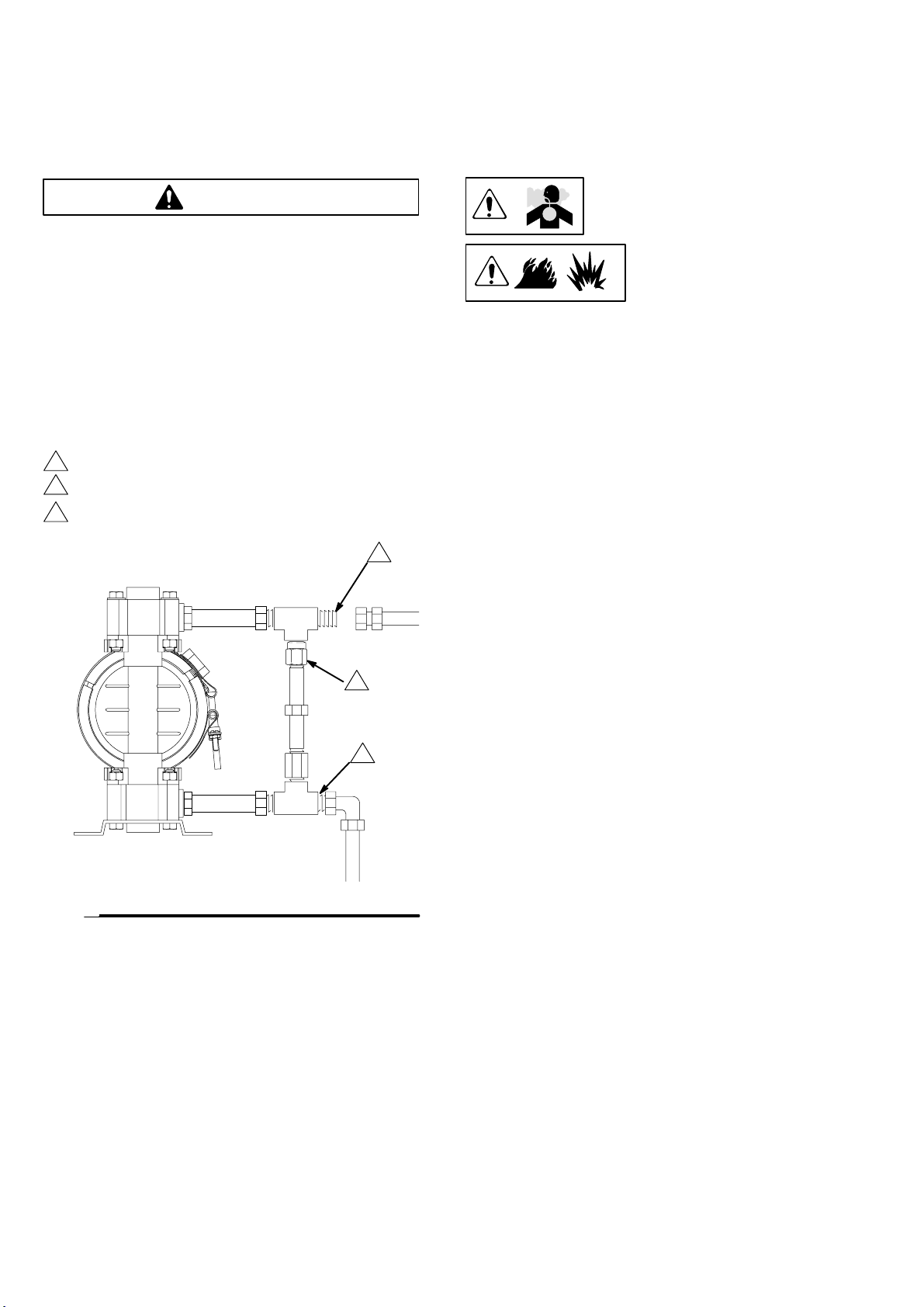
Fluid Pressure Relief Valve
Caution
Some systems may require installation of a pressure relief
valve at the pump outlet to prevent over–pressurization and
rupture of the pump or hose. See Fig. 1.
Thermal expansion of fluid in the outlet line can cause over–
pressurization. This can occur when using long fluid lines
exposed to sunlight or ambient heat, or when pumping from a
cool to a warm area (for example, from an underground tank).
Over–pressurization can also occur if the VERDERAIR pump
is being used to feed fluid to a piston pump, and the intake
valve of the piston pump does not close, causing fluid to back
up in the outlet line.
1
Install valve between fluid inlet and outlet ports.
2
Connect fluid inlet line here.
3
Connect fluid outlet line here.
3
Air Exhaust Ventilation
Read Toxic Fluid Hazard on
page 3.
Read Fire and Explosion
Hazard on page 3.
Be sure the system is properly ventilated for your type of
installation. You must vent the exhaust to a safe place,
away from people, animals, food handling areas, and all
sources of ignition when pumping flammable or hazardous
fluids.
Diaphragm failure will cause the fluid being pumped to
exhaust with the air. Place an appropriate container at the
end of the air exhaust line to catch the fluid. See Fig. 2.
The air exhaust port is 3/8 npt(f). Do not restrict the air exhaust port. Excessive exhaust restriction can cause erratic
pump operation.
Fig. 1
See Venting Exhaust Air in Fig. 2. Exhaust to a remote
location as follows:
1
2
9073A
1. Remove the muffler (W) from the pump air exhaust port.
2. Install an electrically conductive air exhaust hose (X)
and connect the muffler to the other end of the hose.
The minimum size for the air exhaust hose is 3/8
in.(10 mm) ID. If a hose longer than 15 ft (4.57 m) is
required, use a larger diameter hose. Avoid sharp bends
or kinks in the hose.
3. Place a container (Z) at the end of the air exhaust line to
catch fluid in case a diaphragm ruptures. See Fig. 2.
6 819.6900
Page 7
Installation
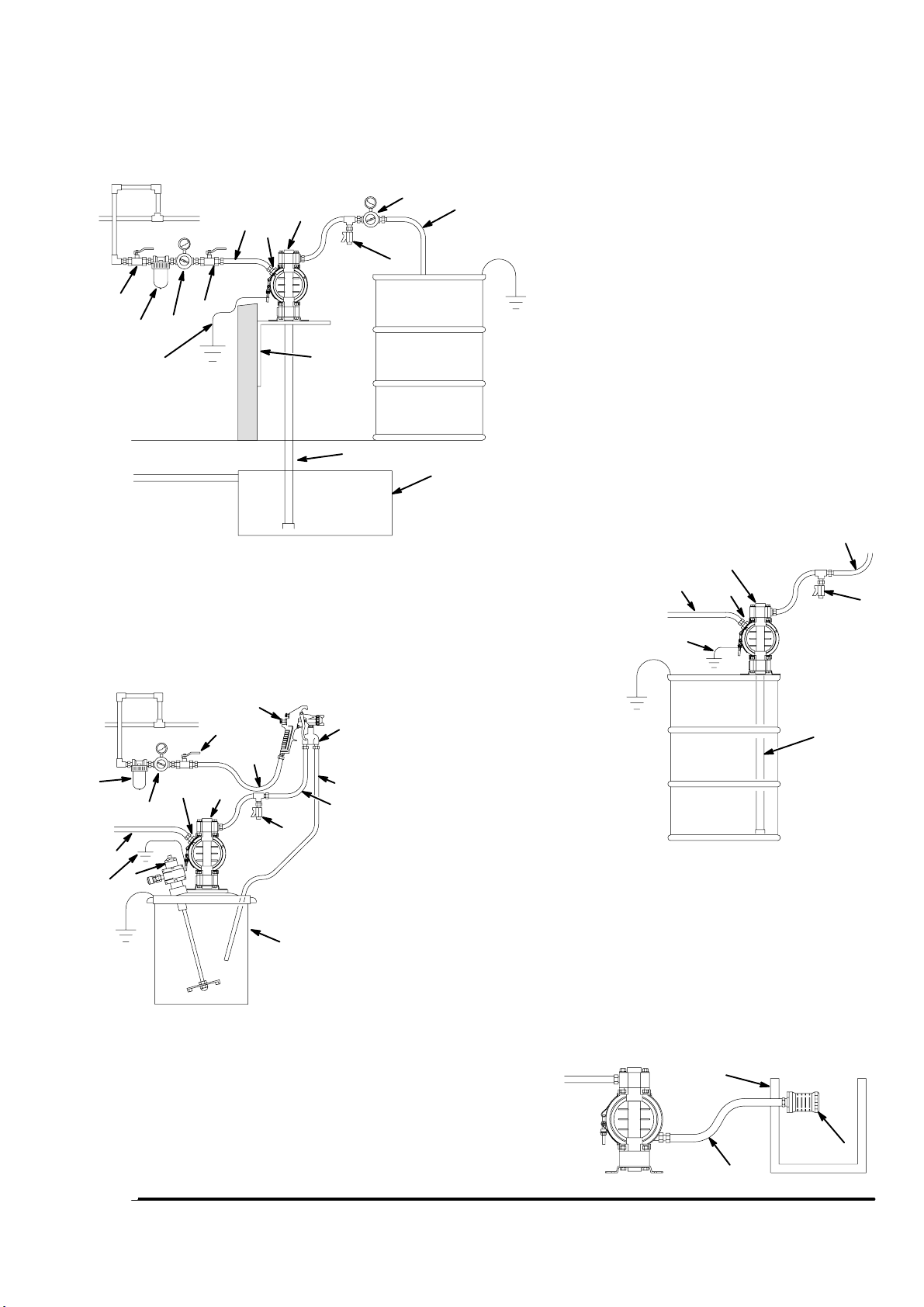
ABOVE-GROUND TRANSFER INSTALLATION
C
A
D
H
E
F
B
G
Y
N
L
KEY
A Pump
C Electrically conductive air supply line
D Air line quick disconnect
H Fluid drain valve (required)
AIR SPRAY INSTALLATION
K Electrically conductive fluid supply hose
L Fluid suction line
Y Ground wire (required; see page 8 for
S
E
R
F
D
A
G
H
C
V
Y
U
P
KEY
A Pump
C Electrically conductive air line to pump
T
E Gun air line shutoff valve
F Air line filter
K
G Gun air regulator
H Fluid drain valve (required)
K Electrically conductive fluid supply hose
P Circulating valve
R Electrically conductive air line to gun
S Air spray gun
T Electrically conductive fluid return line
U 19-liter pail
V Agitator
Y Ground wire (required; see page 8 for
installation instructions)
J
K
9074A
M
installation instructions)
KEY
A Pump
B Bleed-type master air valve (required for pump)
C Electrically conductive air supply line
D Air line quick disconnect
E Master air valve (for accessories)
F Air line filter
G Pump air regulator
H Fluid drain valve (required)
J Fluid regulator (optional)
K Electrically conductive fluid supply hose
L Fluid suction line
M Underground storage tank
N Wall mounting bracket
Y Ground wire (required; see page 8 for installation
instructions)
208-LITER BUNG PUMP INSTALLATION
A
C
D
Y
K
H
L
9075A
Fig. 2
9076A
KEY
W Muffler
X Electrically Conductive Air Exhaust Hose
Z Container for Remote Air Exhaust
All wetted and non-wetted pump parts must be
compatible with the fluid being pumped.
VENTING EXHAUST AIR
Z
X
819.6900 7
W
04054
Page 8
Installation
Grounding
Warning
FIRE AND EXPLOSION HAZARD
This pump must be grounded. Before operating
the pump, ground the system as explained
below. Also read the section Fire and Explo-
sion Hazard on page 3.
The acetal and conductive polypropylene
VERDERAIR VA 15 pumps contain a conduc-
tive additive that makes the wetted parts con-
ductive. Attaching the ground wire to the grounding screw
(106) grounds the wetted parts. See grounding screw on
page 25.
T
he metal M60 pumps have a grounding strip connecting
the vee clamps (109). Attach a ground wire to the grounding
strip with the screw, lockwasher, and nut as shown in the
Grounding Detail on page 28.
The non–conductive polypropylene and PVDF VERDERAIR
VA 15 pumps are not conductive.
When pumping conductive flammable fluids, always ground
the entire fluid system by making sure the fluid system has
an electrical path to a true earth ground (see Fig. 3). Never
use a non–conductive polypropylene or PVDF pump with
non-conductive flammable fluids as specified by your local
fire protection code.
US Code (NFPA 77 Static Electricity) recommends a conductivity greater than 50 x 10
ter) over your operating temperature range to reduce
the hazard of fire. Consult your fluid supplier to determine
the conductivity or resistivity of your fluid. The resistivity
must be less than 2 x 10
–12
Siemans/meter (ohms/me-
12
ohm-centimeters.
Ground all of this equipment:
Pump: The metal pump has a grounding strip in front of
the center housing. The acetal and conductive polypropylene pumps have a grounding screw on the top manifold.
Connect the non-clamp end of the ground wire to the
grounding strip or grounding screw, and connect the
clamp end of the ground wire to a true earth ground. To
order a ground wire and clamp, order Part No. 819.0157.
Air and fluid hoses: Use only electrically conductive
hoses.
Air compressor: Follow the manufacturer’s recommenda-
tions.
Solvent pails used when flushing: Follow the local code.
Use only grounded metal pails, which are conductive. Do
not place the pail on a non-conductive surface, such as
paper or cardboard, which interrupts the grounding continuity.
Fluid supply container: Follow the local code.
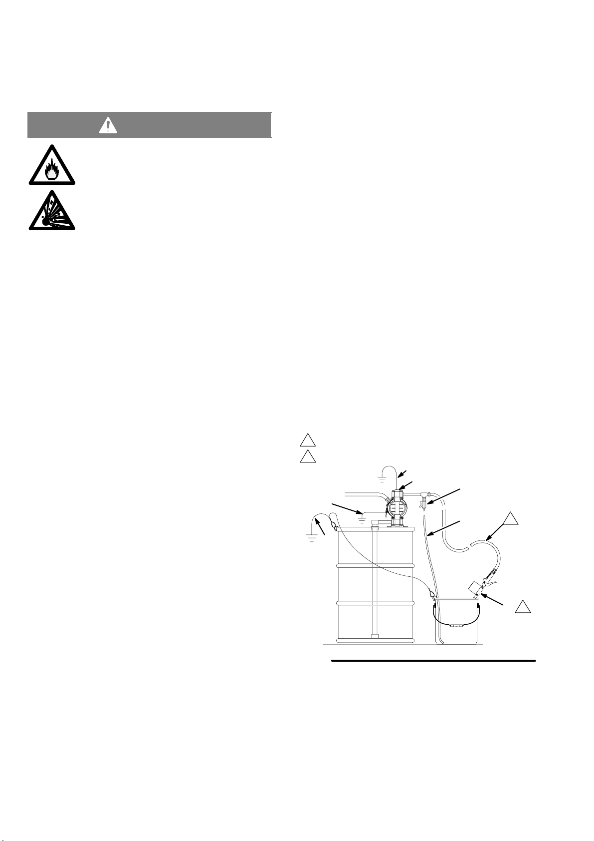
GROUNDING A PUMP
KEY
A Pump
H Fluid drain valve (required)
S Dispense valve
T Fluid drain line
Y Fluid section grounding via grounding strip or grounding
screw (required for metal and acetal pumps)
Z Container ground wire (required)
1
Hose must be conductive.
2
Dispense valve nozzle must be in contact with container.
Y
A
H
Y
T
1
To reduce the risk of static sparking, ground the pump and all
other equipment used or located in the pumping area. Check
your local electrical code for detailed grounding instructions
for your area and type of equipment.
NOTE: When pumping conductive flammable fluids with a
non–conductive polypropylene or PVDF pump, al-
ways ground the fluid system. See the warning
above. Fig. 3 shows a recommended method of
grounding flammable fluid containers during filling.
8 819.6900
Fig. 3
Z
2
S
9079A
Page 9
Installation
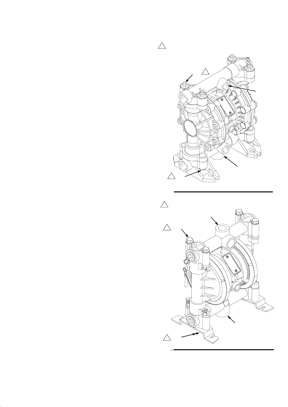
Changing the Orientation of the Fluid Inlet and
Outlet Ports VM60)
You can change the
ports by repositioning the manifolds. For M60, , see Fig. 5.
1. Remove the four manifold nuts (109) or bolts (105).
2. Turn the manifold to the desired position, reinstall the
nuts or bolts, and torque to 80 to 90 in-lb (9 to 10 Nm).
See Torque Sequence, page 30.
NOTE: Make sure all manifold o-rings are positioned
NOTE: Pumps with duckbill check valves are shipped with
the inlet manifold on top and the outlet manifold on
the bottom. See page 14 for details.
orientation of the fluid inlet and outlet
correctly before you fasten the manifold.
Manifold o-rings (139) are shown in Fig. 7
and Fig. 8.
Torque to 80 to 90 in-lb (9 to 10 Nm). See Torque
1
Sequence, page 30.
1
109
1 109
outlet
inlet
Fig. 4
Torque to 80 to 90 in-lb (9 to 10 Nm). See Torque
1
Sequence, page 30.
outlet
1
105
9065A
inlet
Fig. 5
1
105
9071A
819.6900 9
Page 10

Operation
Pressure Relief Procedure
Warning
PRESSURIZED EQUIPMENT HAZARD
The equipment stays pressurized until pressure is
manually relieved. To reduce the risk of serious injury
from pressurized fluid, accidental spray, or splashing fluid,
follow this procedure whenever you:
Are instructed to relieve pressure;
Stop pumping;
Check, clean or service any system equipment;
Install or clean fluid nozzles.
1. Shut off the air to the pump.
2. Open the dispensing valve, if used.
3. Open the fluid drain valve to relieve all fluid pressure,
and have a container ready to catch the drainage.
4. Check all fittings to be sure they are tight. Use a compatible liquid thread sealant on all male threads. Tighten the
fluid inlet and outlet fittings snugly. Do not over–tighten
the fittings into the pump.
5. Place the suction tube (if used) in the fluid to be pumped.
NOTE: If the inlet fluid pressure to the pump is more than
25% of the outlet working pressure, the ball check
valves will not close fast enough, resulting in inefficient pump operation.
6. Place the end of the fluid hose (K) into an appropriate
container.
7. Close the fluid drain valve (H).
8. With the pump air regulator (G) closed, open all bleedtype master air valves (B, E).
9. If the fluid hose has a dispensing device, hold it open
while continuing with the following step. Slowly open the
air regulator (G) until the pump starts to cycle. Allow the
pump to cycle slowly until all air is pushed out of the lines
and the pump is primed.
If you are flushing, run the pump long enough to
thoroughly clean the pump and hoses. Close the air
regulator. Remove the suction tube from the solvent
and place it in the fluid to be pumped.
Flush the Pump Before First Use
The pump was tested with water. Prior to first use, flush the
pump thoroughly with a compatible solvent. Follow the steps
under Starting and Adjusting the Pump.
Starting and Adjusting the Pump
1.
2.
3.
If lifting the pump, follow the Pressure
Relief Procedure above.
Read Toxic Fluid Hazard on
page 3.
Be sure the pump is
properly grounded.
Read Fire and Explo-
sion Hazard on
page 3.
Operation of Remote Piloted Pumps
1. Follow steps 1–8 above.
2. Open the air regulator (G).
Warning
The pump may cycle once before the external signal is
applied.
3. The pump will operate when air pressure is alternately
applied to the push type connectors (16).
NOTE: Leaving air pressure applied to the air motor for ex-
tended periods when the pump is not running may
shorten the diaphragm life. Using a 3–way solenoid
valve to automatically relieve the pressure on the air
motor when the metering cycle is complete prevents
this from occurring.
Pump Shutdown
At the end of the work shift, relieve the
pressure as described in Pressure Relief Procedure at left.
10 819.6900
Page 11

Maintenance
Lubrication
The air valve is lubricated at the factory to operate without
additional lubrication. If you want to provide additional lubrication, remove the hose from the pump air inlet and add two
drops of machine oil to the air inlet every 500 hours of operation or every month.
Caution
Do not over-lubricate the pump. Oil is exhausted through the
muffler, which could contaminate your fluid supply or other
equipment. Excessive lubrication can also cause the pump to
malfunction.
Flushing and Storage
Flush the pump to prevent the fluid you are pumping from
drying or freezing in the pump and damaging it. Use a compatible solvent.
Always flush the pump and relieve the pressure before you
store it for any length of time.
Read Pressure Relief Procedure on
page 10.
Tightening Threaded Connections
Before each use, check all hoses for wear or damage and
replace as necessary. Check to be sure all threaded connections are tight and leak-free.
Check fasteners. Tighten or retorque as necessary. Although pump use varies, a general guideline is to retorque
fasteners every two months. See Torque Sequence, page
30.
Preventive Maintenance Schedule
Establish a preventive maintenance schedule, based on
the pump’s service history. This is especially important for
prevention of spills or leakage due to diaphragm failure.
819.6900 11
Page 12

Troubleshooting
Read Pressure Relief Procedure on page 10, and relieve the pressure before you check or service the equipment. Check all possible problems and causes before disassembling the pump.
PROBLEM CAUSE SOLUTION
Pump will not cycle, or cycles once and
stops.
Pump cycles at stall or fails to hold
pressure at stall.
Pump operates erratically. Clogged suction line. Inspect; clear.
Air bubbles in fluid. Suction line is loose. Tighten.
Fluid in exhaust air. Diaphragm ruptured. Replace.
Pump exhausts air from clamps
(metal pumps).
Pump leaks fluid from check valves. Worn or damaged check valve o-rings. Inspect; replace.
Air valve is stuck or dirty. Use filtered air.
Leaky check valves or o-rings. Replace.
Worn check balls or duckbill valves or
guides.
Check ball wedged in guide. Repair or replace.
Worn diaphragm shaft seals. Replace.
Sticky or leaking check valve balls. Clean or replace.
Diaphragm ruptured. Replace.
Diaphragm ruptured. Replace.
Loose manifolds or damaged manifold
o-rings.
Loose fluid side diaphragm plates. Tighten.
Loose fluid side diaphragm plates. Tighten.
Worn diaphragm shaft seals. Replace.
Loose clamps. Tighten clamp nuts.
Air valve o-ring is damaged. Inspect; replace.
Replace.
Tighten manifold bolts or nuts; replace
o-rings.
12 819.6900
Page 13

Service
Air Valve M60 Pumps)
NOTE: Air Valve Repair Kit 819.9740 is available. Parts included in the kit are marked with a dagger () in Fig. 6 and in the Parts
Drawings and Lists. A tube of general purpose grease 819.0184 is supplied in the kit. Service the air valve as follows.
See Fig. 6.
1. Relieve the pressure. See Pres-
sure Relief Procedure on page 10.
2. Remove the cover (10) and the o-ring (4).
3. Remove the carriage plungers (7), carriages (8),
carriage pins (9), and valve plate (14) from the center
housing (11).
4. Clean all the parts, and inspect them for wear or
damage.
NOTE: If you are installing the new Air Valve Repair
Kit 819.9740, use all the parts in the kit.
5. Grease the lapped surface of the valve plate (14), and
install the valve plate with the lapped surface facing up.
6. Grease the bores of the center housing (11), install the
u-cup packings (2) on the carriage plungers (7), and
slide the carriage plungers into the carriage plunger
bores. See the following important installation notes:
NOTES:
When you install each u-cup packing (2) on each carriage
plunger (7), make sure the lips of the u-cup packing face
toward the clip end (the smaller end) of the carriage
plunger.
When you slide the carriage plungers (7) into the bores,
slide them in with the clip ends (the smaller ends) facing
toward the center of the center housing (11).
7. Grease the carriage pins (9), and slide the carriage pins
into the carriage pin bores.
8. Install the carriages (8). Make sure the carriages engage
the clip ends of the carriage plungers (7) and carriage
pins (9).
9. Grease the o-ring (4), and seat it in the groove around
the cover opening of the center housing (11).
10. Screw cover (10) into center housing, and torque cover
from 80 to 100 in–lb (9.0 to 13.6 Nm).
NOTE: Center housing (11) is shown separated from the
air covers, but it is not necessary to remove the air
covers for this service. Leave the center housing
and air covers assembled for this service.
5
Included in Air Valve Repair Kit 819.9740.
1
Torque to 80 to 100 in-lb (9.0 to 13.6 Nm).
2
Apply grease.
3
Apply grease to lapped face.
4
Apply grease to bores of center housing (11) before installing.
5
Seal lips face clip end (the smaller end) of carriage plunger (7).
Install with the clip ends (the smaller ends) facing toward center of
6
center housing (11).
Fig. 6
8
1
10
4
5
2
4
2
4 6
7
4 6
7
3
14
2
4
11
2
9
8
9
2
9069A
819.6900 13
Page 14

Service
Ball or Duckbill Check Valves
NOTE: Fluid Section Repair Kit is available. See page 23
to order the correct kit for your pump. Parts included
in the kit are marked with a double dagger () in
Fig. 7 and Fig. 8 and in the Parts Drawings and Lists.
General purpose grease 819.0184 and Adhesive
819.9741 are supplied in the kit.
1. Relieve the pressure. See Pres-
sure Relief Procedure on page 10.
2. Remove the top and bottom manifolds (102, 103).
3. Remove all parts shown with a dagger () in Fig. 7 and
Fig. 8.
4. Clean all parts, and replace worn or damaged parts.
5. Reassemble the pump.
NOTE: Torque the manifold nuts (109) or bolts (105) to
80 to 90 in-lb (9 to 10 Nm). See Torque Se-
quence, page 30.
Inlet and Outlet for Pumps with Duckbill
Check Valves
Pumps with duckbill check valves are shipped with the inlet
manifold on top and the outlet manifold on the bottom. To
make the inlet manifold on the bottom and the outlet manifold
on the top, rotate each of the four duckbill assemblies vertically 180 as shown below.
139
201
202
9080A
14 819.6900
Page 15

Service
Diaphragms M60
NOTE: Fluid Section Repair Kit is available. See page 23 to order the correct kit for your pump. Parts included in the kit are
marked with a double dagger () in Fig. 10 and in the Parts Drawings and Lists. General purpose grease 819.0184 and
Adhesive 819.9741 are supplied in the kit. Service the diaphragms as follows. See Fig. 10.
Disassembly
1. Relieve the pressure. See Pressure Relief Procedure on page 10.
2. Remove the manifolds (102) and fluid covers (101).
NOTE: Make sure all the check valve parts stay in
place. See Fig. 8 on page 15.
3. Remove the grounding strip from the vee clamps (109),
and remove the vee clamps.
4. Remove one of the fluid-side diaphragm plates (133)
(whichever one comes loose first when you use a
wrench on the hex of each), and pull the diaphragm
shaft out of the center housing (11).
5. Use a wrench on the flats of the diaphragm shaft (15) to
remove the other fluid-side diaphragm plate (133) from
the diaphragm shaft.
6. Remove the screws (141) and air covers (136), and
remove all old gasket (12) material from the ends of the
center housing (11) and the surfaces of the air covers.
7. Remove the diaphragm shaft u-cups (16) and pilot pin
o-rings (1).
8. Inspect all parts for wear or damage, and replace as
necessary.
3. Position the exhaust cover (13) and o-ring (4) on the
center housing (11).
4. Repeat steps 1 and 2 for the other end of the center
housing and the remaining air cover.
5. Apply medium-strength (blue) Loctite or equivalent to
the threads of the screws (140). Install on one end of
the diaphragm shaft (15) the following parts (see
proper order in Fig. 10): air-side diaphragm plate (6),
diaphragm (401), fluid-side diaphragm plate (133),
o-ring (115), and screw (140).
NOTE: The words “AIR SIDE” on the diaphragm (401)
and the flat side of the air-side diaphragm
plate (6) must face toward the diaphragm
shaft (15).
6. Put grease on the diaphragm shaft (15), and carefully
(do not damage the shaft u-cups) run the diaphragm
shaft (15) through the center housing (11) bore.
7. Repeat step 5 for the other end of the diaphragm
shaft (15), and torque the diaphragm shaft screws (140)
to 80 to 90 in-lb (9 to 10 Nm) at 100 rpm maximum.
8. Install the muffler (3).
When you install the vee clamps in step 9, orient the center
housing (11) so the air inlet is approximately 45 above horizontal and the muffler (3) is approximately horizontal.
Reassembly
1. Insert a diaphragm shaft u-cup (16) and a pilot pin
o-ring (1) into the end of the diaphragm shaft bore of
the center housing (11).
NOTE: Make sure the lips of the u-cup face out of the
center housing.
2. Line up the holes in the gasket (12) with the holes in the
end of the center housing (11), and use six screws (141)
to fasten an air cover (136) to the end of the center
housing (11). Torque the screws to 35 to 45 in-lb (4.0 to
5.1 Nm).
18 819.6900
9. Apply thin film of grease to inside of vee clamps (109).
10. Position the fluid covers (101), install the vee
clamps (109) around the fluid and air covers, install the
grounding strip on the vee clamps, and torque the vee
clamp nuts to 80 to 90 in–lb (9 to 10 Nm). See Torque
Sequence, page 30.
11. Make sure all the check valve parts are in place. See
Fig. 8 on page 15.
12. Install the manifolds (102), and torque the manifold
bolts (105) to 80 to 90 in-lb (9 to 10 Nm). See Torque
Sequence, page 30.
Page 16

Service
Diaphragms M60
105
7
102
101
11
1
16
4
13
141
2
3
12
136
3
109
4
402 6
5
102
105
4
401
3
15
1
115
6
7
Included in Fluid Section Repair Kit.
1
2
3
4
5
6
133
140
Install with lips facing out of center housing (11).
Torque to 35 to 45 in-lb (4.0 to 5.1 Nm).
Apply grease.
The words “AIR SIDE” on diaphragm and backup diaphragm must face toward
diaphragm shaft (15).
Flat side of the air-side diaphragm plate must face toward diaphragm shaft (15).
Apply medium-strength (blue) Loctite or equivalent to threads, and torque to
80 to 90 in-lb (9 to 10 Nm) at 100 rpm maximum.
16
Fig. 10
7
Torque to 80 to 90 in-lb (9 to 10 Nm). See Torque
Sequence, page 30.
9072A
819.6900 19
Page 17

M60 Pump Listing
Your Model No. is marked on the pump’s serial plate. See the listing of existing VERDERAIR VA 20 pumps below:
M60 Standard Air
Fluid
Ref. No.
810.6815 AL AC TF TF
810.6816 AL AC TF TPE
810.6817 AL AC SS TF
810.6818 AL AC TPE TPE
810.6819 AL AC SP SP
810.6820 AL AC BN BN
810.6821 AL AC FE FE
810.6822 AL SS TF TF
810.6823 AL SS TF TPE
810.6824 AL SS SS TF
810.6825 AL SS SS TPE
810.6826 AL SS SS SP
810.6827 AL SS SS BN
810.6828 AL SS SS FE
810.6829 AL SS TPE TPE
810.6830 AL SS SP SP
810.6831 AL SS BN BN
810.6832 AL SS FE FE
810.6833 AL PP TF TF
810.6834 AL PP TPE TPE
810.6835 AL PP SP SP
810.6836 AL PP BN BN
810.6837 SS AC TF TF
810.6838 SS AC SS TF
810.6839 SS SS TF TF
810.6840 SS SS SS TF
810.6841 SS SS SS TPE
810.6842 SS SS SS SP
810.6843 SS SS BN BN
810.6844 SS SS FE TF
810.6845 SS SS FE FE
810.6846 SS PP TF TF
810.6847 AL AC SS BN
810.6852 AL PP SP SP
810.6853 AL SS BN BN
810.6854 AL SS TF TF
810.6855 SS SS TF TF
Section
Valve
Seats
and
Guides
Checks Diaphragms
M60 for Solenoid Operation
Seats
Fluid
Ref. No.
810.6939 AL AC TF TF
810.6940 AL AC TF TPE
810.6941 AL AC SS TF
810.6942 AL AC TPE TPE
810.6943 AL AC SP SP
810.6944 AL AC BN BN
810.6945 AL AC FE FE
810.6946 AL SS TF TF
810.6947 AL SS TF TPE
810.6948 AL SS SS TF
810.6949 AL SS SS TPE
810.6950 AL SS SS SP
810.6951 AL SS SS BN
810.6952 AL SS SS FE
810.6953 AL SS TPE TPE
810.6954 AL SS SP SP
810.6955 AL SS BN BN
810.6956 AL SS FE FE
810.6957 AL PP TF TF
810.6958 AL PP TPE TPE
810.6959 AL PP SP SP
810.6960 AL PP BN BN
810.6961 SS AC TF TF
810.6962 SS AC SS TF
810.6963 SS SS TF TF
810.6964 SS SS SS TF
810.6965 SS SS SS TPE
810.6966 SS SS SS SP
810.6967 SS SS BN BN
810.6968 SS SS FE TF
810.6969 SS SS FE FE
810.6970 SS PP TF TF
810.6971 AL AC SS BN
Section
and
Guides
Checks Diaphragms
AL = Aluminium AC = Acetal BN = Buna-N TPE = Thermoplastic Polyester Elastomer PP = Polypropylene SP = Santoprene
SS = Stainless Steel TF = PTFE FE = Fluoroelastomer
810.6852, 810.6853, 810.6854, and 810.6855 have npt threads.
22 819.6900
Page 18

M 60 Repair Kits
NOTE: Order Repair Kits separately.
To order the Air Valve Repair Kit, order Part No. 819.9740.
Seats
and
Ref. No.
819.5183 PP FE FE
819.5176 PP BN BN
819.5172 PP BN ––
819.5169 PP SP SP
819.5162 PP TPE TPE
819.5149 PP TF TF
819.5148 PP TF ––
819.5135 SS FE FE
819.5130 SS FE ––
819.5128 SS BN BN
819.5124 SS BN ––
819.5107 SS SS TF
819.5101 SS TF TF
819.5100 SS TF ––
819.5080 AC BN BN
819.5076 AC BN ––
819.5066 AC TPE TPE
819.5059 AC SS TF
819.5054 AC TF TPE
8195053 AC TF TF
819.5052 AC TF ––
819.5010 SS Checks
819.5003 FE Diaphragms
819.5002 BN Diaphragms
819.5001 SP Diaphragms
819.4999 TF Diaphragms
819.5121 SS SP SP
Guides
Checks Diaphragms
AL = Aluminium AC = Acetal BN = Buna-N TPE = Thermoplastic Polyester Elastomer PP = Polypropylene SP = Santoprene
SS = Stainless Steel TF = PTFE FE = Fluoroelastomer
Kit Description
819.6992 Sensor
Includes 1 each of reed switch and carriage assembly
819.6993 Sensor with Counter
Includes 1 each of reed switch, counter, bracket, and
carriage assembly
819.6900 23
Page 19

M 60 Parts Drawing
Included in Air Valve Repair Kit 819.9740
Included in Fluid Section Repair Kits 819.4997 to
819.5189
10
8
7
2
* These parts are unique to the remote operated air motor.
105
102
103
107
112
202
201
139
202
301
201
139
139
106
104
101
401
16
12
402
141
4
14
9
17
11
1
16
4
13
3
15
16
6
106
112
202
301
102
105
117
139
201
139
202
201
139
108
109
140
133
115
Grounding Detail
123
122
121
110
9070A
28 819.6900
Page 20

M 60 Fluid Section Parts List
See page 24 for Air Motor Parts List
M 60 Fluid Section Parts List
Ref.
No.
115 819.6557 O-RING; PTFE 2 819.6557 O-RING; PTFE 2
139 819.4432 O-RING; PTFE 8 819.4432 O-RING; PTFE 8
Part No.
101 819.4457 COVER, fluid; aluminum 2 819.4467 COVER, fluid; sst 2
102 819.6964 MANIFOLD; aluminum; BSPT 2 819.6970 MANIFOLD; sst; BSPT 2
819.4458 MANIFOLD; aluminum; NPT (for
103 819.4434 LABEL, warning 1 819.4434 LABEL, warning 1
104 819.6965 LABEL, identification 1 819.6965 LABEL, identification 1
105 819.4459 SCREW; 3/8–16; 2.25 in. (57.2 mm) 8 819.4459 SCREW; 3/8–16; 2.25 in. (57.2 mm) 8
106 819.4460 NUT, hex; 3/8–16; sst 8 819.4460 NUT, hex; 3/8–16; sst 8
107 819.4461 WASHER, flat; 3/8 in.; sst 4 819.4461 WASHER, flat; 3/8 in.; sst 4
108 819.4462 BASE, feet 2 819.4462 BASE, feet 2
109 819.4433 CLAMP, vee 2 819.4433 CLAMP, vee 2
110 819.0198 NUT, clamp; 1/4–28 2 819.0198 NUT, clamp; 1/4–28 2
111 819.6354 STRIP, grounding 1 819.6354 STRIP, grounding 1
112 819.6967 PLUG, steel; BSPT 2 819.6971 PLUG; sst; BSPT 2
819.4463 PLUG, steel; NPT (for 810.6852,
117 819.4466 LABEL, warning 1
121 819.6880 SCREW; 10–24; 0.31 in. (8 mm) 1 819.6880 SCREW; 10–24; 0.31 in. (8 mm) 1
122 819.0187 LOCKWASHER; #10 1 819.0187 LOCKWASHER; #10 1
123 819.0185 NUT, hex; 10–24 1 819.0185 NUT, hex; 10–24 1
133 819.6968 PLATE, diaphragm, fluid side; sst 2 819.0356 PLATE, diaphragm, fluid side; sst
136 819.6969 COVER air 2 819.6969 COVER air 2
140 819.6556 SCREW, flange; hex head 2 819.6556 SCREW, flange; hex head 2
141 819.6936 SCREW, machine 12 819.6936 SCREW, machine 12
142 819.6943 RIVET (for plate 134) 2 819.6943 RIVET (for plate 134) 2
Aluminum Pumps Stainless Steel (sst) Pumps
Description Qty Part No. Description Qty
2 819.4468 MANIFOLD; sst; NPT
810.6852, 810.6853, and 810.6854
only)
2 819.4469 PLUG; sst; NPT (for 810.6855 only) 2
810.6853, and 810.6854 only)
(for 810.6855 only)
machined
2
2
Included in Fluid Section Repair Kit.
819.6900 29
Page 21

Torque Sequence
Always follow torque sequence when instructed to torque fasteners.
M 1
5
1. Left/Right Fluid Covers
Torque bolts to 80–90 in–lb (9–10 Nm)
1111
88
6
4
SIDE VIEW
3
5
7
2
2. Inlet Manifold
Torque bolts to 80–90 in–lb (9–10 Nm)
11
10
M
60
1. Left/Right Fluid Covers
Torque bolts to 80–90 in–lb (9–10 Nm)
2
FRONT VIEW
1
2. Inlet Manifold
Torque bolts to 80–90 in–lb (9–10 Nm)
5
3
9
BOTTOM VIEW
12
3. Outlet Manifold
Torque bolts to 80–90 in–lb (9–10 Nm)
13
15
TOP VIEW
16
14
4
4
BOTTOM VIEW
6
6
3. Outlet Manifold
Torque Bolts to 80–90 in–lb (9–10 Nm)
9
8
TOP VIEW
7
10
30 819.6900
Page 22

M 60 Technical Data
Maximum fluid working pressure 100 psi; 0.7 MPa (7 bar). . . . . . . . . . . . . . . . . . . . . . . . . . . . . . . . . . . . . . . . . . . . . . . . . . . . . . . . . .
Air pressure operating range 30 to 100 psi; 0.18 to 0.7 MPa (1.8 to 7 bar). . . . . . . . . . . . . . . . . . . . . . . . . . . . . . . . . . . . . . . . . . . .
Maximum air consumption 28 scfm; 0.793 cubic meters/min.. . . . . . . . . . . . . . . . . . . . . . . . . . . . . . . . . . . . . . . . . . . . . . . . . . . . . . .
Maximum free flow delivery 16 gpm; 61 l/min.. . . . . . . . . . . . . . . . . . . . . . . . . . . . . . . . . . . . . . . . . . . . . . . . . . . . . . . . . . . . . . . . . . . .
Maximum pump speed 400 cpm. . . . . . . . . . . . . . . . . . . . . . . . . . . . . . . . . . . . . . . . . . . . . . . . . . . . . . . . . . . . . . . . . . . . . . . . . . . . . . .
Liters per cycle 0.15. . . . . . . . . . . . . . . . . . . . . . . . . . . . . . . . . . . . . . . . . . . . . . . . . . . . . . . . . . . . . . . . . . . . . . . . . . . . . . . . . . . . . . . . .
Maximum suction lift (water) 15 ft; 4.5 m dry,. . . . . . . . . . . . . . . . . . . . . . . . . . . . . . . . . . . . . . . . . . . . . . . . . . . . . . . . . . . . . . . . . . . . .
25 ft; 7.6 m wet
Maximum size pumpable solids 3.32 in.; 2.5 mm. . . . . . . . . . . . . . . . . . . . . . . . . . . . . . . . . . . . . . . . . . . . . . . . . . . . . . . . . . . . . . . . .
Sound power level (measured per ISO standard 9614–2)
At 70 psig; 0.48 MPa (4.8 bar) at 50 cycles per minute 77 dBa. . . . . . . . . . . . . . . . . . . . . . . . . . . . . . . . . . . . . . . . . . . . . . . . . . . .
At 100 psig; 0.7 MPa (7 bar) at maximum cycles per minute 95 dBa. . . . . . . . . . . . . . . . . . . . . . . . . . . . . . . . . . . . . . . . . . . . . . .
Sound pressure level (measured 1 meter from pump)
At 70 psig; 0.48 MPa (4.8 bar) bar at 50 cycles per minute 67 dBa. . . . . . . . . . . . . . . . . . . . . . . . . . . . . . . . . . . . . . . . . . . . . . . .
At 100 psig; 0.7 MPa (7 bar) at maximum cycles per minute 85 dBa. . . . . . . . . . . . . . . . . . . . . . . . . . . . . . . . . . . . . . . . . . . . . . .
Air inlet size 1/4 npt(f). . . . . . . . . . . . . . . . . . . . . . . . . . . . . . . . . . . . . . . . . . . . . . . . . . . . . . . . . . . . . . . . . . . . . . . . . . . . . . . . . . . . . . . .
Air exhaust port size 3/8 npt(f). . . . . . . . . . . . . . . . . . . . . . . . . . . . . . . . . . . . . . . . . . . . . . . . . . . . . . . . . . . . . . . . . . . . . . . . . . . . . . . . .
Fluid inlet size. 3/4 bspt(f). . . . . . . . . . . . . . . . . . . . . . . . . . . . . . . . . . . . . . . . . . . . . . . . . . . . . . . . . . . . . . . . . . . . . . . . . . . . . . . . . . . . .
819.6852, 819.6853, 819.6854, and 819.6855 only 3/4 npt(f). . . . . . . . . . . . . . . . . . . . . . . . . . . . . . . . . . . . . . . . . . . . . . . . . . . .
Fluid outlet size. 3/4 bspt(f). . . . . . . . . . . . . . . . . . . . . . . . . . . . . . . . . . . . . . . . . . . . . . . . . . . . . . . . . . . . . . . . . . . . . . . . . . . . . . . . . . . .
819.6852, 819.6853, 819.6854, and 819.6855 only 3/4 npt(f). . . . . . . . . . . . . . . . . . . . . . . . . . . . . . . . . . . . . . . . . . . . . . . . . . . .
Wetted parts (in addition to ball, seat, and diaphragm materials, which vary by pump)
Aluminum pumps aluminum, stainless steel, PTFE, zinc-plated steel. . . . . . . . . . . . . . . . . . . . . . . . . . . . . . . . . . . . . . . . . . . . . .
Stainless steel pumps 316 stainless steel, PTFE. . . . . . . . . . . . . . . . . . . . . . . . . . . . . . . . . . . . . . . . . . . . . . . . . . . . . . . . . . . . . . . .
Non-wetted external parts polypropylene, stainless steel, polyester (labels),. . . . . . . . . . . . . . . . . . . . . . . . . . . . . . . . . . . . . . . . . . .
nickel-plated brass, epoxy-coated steel (feet)
Weight (approximate)
Aluminum pumps 8.5 lb; 3.9 kg. . . . . . . . . . . . . . . . . . . . . . . . . . . . . . . . . . . . . . . . . . . . . . . . . . . . . . . . . . . . . . . . . . . . . . . . . . . . .
Stainless steel pumps 18 lb; 8.2 kg. . . . . . . . . . . . . . . . . . . . . . . . . . . . . . . . . . . . . . . . . . . . . . . . . . . . . . . . . . . . . . . . . . . . . . . . . . .
Santoprener is a registered trademark of the Monsanto Company.
Loctiter is a registered trademark of the Loctite Corporation.
819.6900 33
Page 23

M 60 Dimensions
FRONT VIEW
* Pumps with duckbill
check valves are shipped
with the inlet manifold on
top and the outlet manifold
on the bottom. To make
the inlet manifold on the
bottom and the outlet
manifold on the top, rotate
each of the four duckbill
assemblies vertically 180
as shown below.
139
201
202
SIDE VIEW
3/4 bspt(f)
Fluid Outlets *
62.5 mm
1/4 npt(f)
Air Inlet
187.2 mm
3/4 bspt(f)
Fluid Inlets *
112.8 mm108.0 mm
168.1 mm
3/4 bspt(f)
Fluid Outlet *
233.2 mm
198.1 mm
35.1 mm
3/4 bspt(f)
Fluid Outlet *
264.9 mm
109.0 mm
153.4 mm
3/4 bspt(f)
Fluid Inlets *
PUMP MOUNTING HOLE PATTERN
7.1 mm Diameter Slots
109.0 mm
168.1 mm
9078A
34 819.6900
Page 24

Performance Charts
Fluid Outlet Pressure
Test Conditions:
Pump tested in water with inlet submerged.
100
(0.7, 7)
A
80
(0.55, 5.5)
60
(0.41, 4.1)
40
(0.28, 2.8)
FLUID OUTLET PRESSURE – psi; MPa (bar)
20
(0.14, 1.4)
0
0246810121416
B
C
(7.6) (15.2) (22.7) (30.3) (37.9) (45.4) (53.0) (60.6)
Fluid Pressure Curves
A at 100 psi (0.7 MPa, 7 bar) air pressure
B at 70 psi (0.48 MPa, 4.8 bar) air pressure
C at 40 psi (0.28 MPa, 2.8 bar) air pressure
FLUID FLOW – gpm (lpm)
To find Fluid Outlet Pressure (psi/MPa/bar) at a specific fluid flow (gpm/lpm) and operating air pressure (psi/MPa/bar):
1. Locate fluid flow rate along bottom of chart.
2. Follow vertical line up to intersection with selected fluid outlet pressure curve.
3. Follow left to scale to read fluid outlet pressure.
819.6900 35
Page 25

Performance Charts
ИИИИИ
ИИИИИ
ИИИИИ
ИИИИИ
Air Consumption
Test Conditions:
Pump tested in water with inlet submerged.
30
(0.84)
Air Consumption Curves
A at 100 psi (0.7 MPa, 7 bar) air pressure
25
(0.70)
(0.56)
(0.42)
(0.28)
AIR CONSUMPTION – scfm; cubic meter/min
(0.14)
B at 70 psi (0.48 MPa, 4.8 bar) air pressure
C at 40 psi (0.28 MPa, 2.8 bar) air pressure
20
15
10
5
0
0246810121416
(7.6) (15.2) (22.7) (30.3) (37.9) (45.4) (53.0) (60.6)
A
B
C
FLUID FLOW – gpm (lpm)
To find Pump Air Consumption (scfm or m/min) at a specific fluid flow (gpm/lpm) and air pressure (psi/MPa/bar):
1. Locate fluid flow rate along bottom of chart.
2. Read vertical line up to intersection with selected air consumption curve.
3. Follow left to scale to read air consumption.
36 819.6900
Page 26

Customer Services/Guarantee
CUSTOMER SERVICES
If you require spare parts, please contact your local distributor, providing the following details:
Pump Model
Type
Serial Number, and
Date of First Order.
GUARANTEE
All VERDER pumps are warranted to the original user against defects in workmanship or materials under normal use (rental use
excluded) for two years after purchase date. This warranty does not cover failure of parts or components due to normal wear,
damage or failure which in the judgement of VERDER arises from misuse.
Parts determined by VERDER to be defective in material or workmanship will be repaired or replaced.
LIMITATION OF LIABILITY
To the extent allowable under applicable law, VERDER’s liability for consequential damages is expressly disclaimed. VERDER’s
liability in all events is limited and shall not exceed the purchase price.
WARRANTY DISCLAIMER
VERDER has made an effort to illustrate and describe the products in the enclosed brochure accurately; however, such illustrations and descriptions are for the sole purpose of identification and do not express or imply a warranty that the products are merchantable, or fit for a particular purpose, or that the products will necessarily conform to the illustration or descriptions.
PRODUCT SUITABILITY
Many regions, states and localities have codes and regulations governing the sale, construction, installation and/or use of products for certain purposes, which may vary from those in neighbouring areas. While VERDER attempts to assure that its products
comply with such codes, it cannot guarantee compliance, and cannot be responsible for how the product is installed or used.
Before purchasing and using a product, please review the product application as well as the national and local codes and regulations, and be sure that product, installation, and use complies with them.
Original instructions. This manual contains English.
Revision ZAA, June 2013
819.6900 37
Page 27

EC-DECLARATION OF CONFORMITY
EG-VERKLARING VAN OVEREENSTEMMING, DÉCLARATION DE CONFORMITÉ CE, EG-KONFORMITÄTSERKLÄRUNG, DICHIARAZIONE DI
CONFORMITÀ CE, EF-OVERENSSTEMMELSESERKLÆRING, ΕΚ-ΔΗΛΩΣΗ ΣΥΜΜΟΡΦΩΣΗΣ, DECLARAÇÃO DE CONFORMIDADE – CE,
DECLARACIÓN DE CONFORMIDAD DE LA CE, EY-VAATIMUSTENMUKAISUUSVAKUUTUS, EG-DEKLARATION OM ÖVERENSSTÄMMELSE,
ES PROHLÁŠENÍ O SHODĚ, EÜ VASTAVUSDEKLARATSIOON, EC MEGFElELŐSÉGI NYILATKOZAT, EK ATBILSTĪBAS DEKLARĀCIJA, ES
ATITIKTIES DEKLARACIJA, DEKLARACJA ZGODNOŚCI UE, DIKJARAZZJONI-KE TA’ KONFORMITA`, IZJAVA ES O SKLADNOSTI, ES -
VYHLÁSENIE O ZHODE, ЕО-ДЕКЛАРАЦИЯ ЗА СЪВМЕСТИМОСТ, DEIMHNIÚ COMHRÉIREACHTA CE, CE-DECLARAŢIE DE CONFORMITATE
Model
Modèle, Modell, Modello, Μοντέλο,
Modelo, Malli, Mudel, Modelis, Mudell, Модел, Samhail
M 60
Part
Bestelnr., Type, Teil, Codice, Del, Μέρος, Peça,
Referencia, Osa, Součást, Részegység, Daļa,
Dalis, Część, Taqsima, Časť, Част, Páirt, Parte
Complies With The EC Directives:
Voldoet aan de EG-richtlijnen, Conforme aux directives CE, Entspricht den EG-Richtlinien, Conforme alle direttive CE, Overholder EF-direktiverne, Σύμφωνα με τις Οδηγίες της ΕΚ, Em
conformidade com as Directivas CE, Cumple las directivas de la CE, Täyttää EY-direktiivien vaatimukset, Uppfyller EG-direktiven, Shoda se směrnicemi ES, Vastab EÜ direktiividele,
Kielégíti az EK irányelvek követelményeit, Atbilst EK direktīvām, Atitinka šias ES direktyvas, Zgodność z Dyrektywami UE, Konformi mad-Direttivi tal-KE, V skladu z direktivami ES, Je v
súlade so smernicami ES, Съвместимост с Директиви на ЕО, Tá ag teacht le Treoracha an CE, Respectă directivele CE
2006/42/EC Machinery Directive
94/9/EC ATEX Directive (EX II 2 GD c IIC T4) – Tech File stored with NB 0359
Standards Used:
Gebruikte maatstaven, Normes respectées , Verwendete Normen, Norme applicate, Anvendte standarder , Πρότυπα που χρησιμοποιήθηκαν, Normas utilizadas, Normas aplicadas,
Sovellettavat standardit, Tillämpade standarder, Použité normy, Rakendatud standardid, Alkalmazott szabványok, Izmantotie standarti, Taikyti standartai, Użyte normy, Standards Użati,
Uporabljeni standardi, Použité normy, Използвани стандарти, Caighdeáin arna n-úsáid , Standarde utilizate
EN 1127-1 EN 13463-1
ISO 12100 ISO 9614-1
Notified Body for Directive
Aangemelde instantie voor richtlijn , Organisme notifié pour la directive , Benannte Stelle für diese Richtlinie, Ente certificatore della direttiva, Bemyndiget organ for direktiv , Διακοινωμένο
όργανο Οδηγίας, Organismo notificado relativamente à directiva, Organismo notificado de la directiva, Direktiivin mukaisesti ilmoitettu tarkastuslaitos, Anmält organ för direktivet, Úředně
oznámený orgán pro směrnici, Teavitatud asutus (direktiivi järgi), Az irányelvvel kapcsolatban értesített testület, Pilnvarotā iestāde saskaņā ar direktīvu, Apie direktyvą Informuota institucija,
Ciało powiadomione dla Dyrektywy, Korp avżat bid-Direttiva, Priglašeni organ za direktivo, Notifikovaný orgán pre smernicu, Нотифициран орган за Директива, Comhlacht ar tugadh fógra
dó, Organism notificat în conformitate cu directiva
810.0383–810.0418, 810.6758–810.6766, 810.6771, 810.6815–810.6847,
810.6852–810.6855, 810.6881–810.6890, 810.6939–810.6971, 810.7004
Approved By:
Goedgekeurd door, Approuvé par, Genehmigt von, Approvato da, Godkendt af , Έγκριση από, Aprovado por, Aprobado por, Hyväksynyt, Intygas av, Schválil, Kinnitanud, Jóváhagyta,
Apstiprināts, Patvirtino, Zatwierdzone przez, Approvat minn, Odobril, Schválené, Одобрено от, Faofa ag, Aprobat de
Frank Meersman
29 December 2009
Director
819.5963
 Loading...