

Page 1
Trabon® Modular MXP
Divider Valves
DESCRIPTION
Modular MXP Divider Valves use a stackable subplate design.
The valve section containing the displacement piston is bolted
to an individual subplate. A complete divider valve assembly
consists of an inlet section, an end section, and a minimum of
three (3) to a maximum of ten (10) stacked subplates and valve
sections. These components are bolted together with three (3)
tie rods.
A complete divider valve assembly with a maximum of ten (10)
subplates and valve sections can serve up to 20 lubrication
points.
Because outlet connections are made to the subplate, valve
sections may be changed without disturbing existing tubing.
More lubrication points may be added to an existing assembly by
installing additional subplates, valve sections, and outlet tubing.
A bypass is available allowing points of lubrication to be deleted
(installing a bypass section) or added (removing an installed
bypass section and replacing it with a valve section).
The amount of lubricant dispensed by each valve section is
determined by the size of the piston. A twin valve section
dispenses equal amounts of lubricant to two (2) outlets. A single
valve section combines the lubricant from both ends of the piston
and dispenses it to one outlet. Existing twin valve sections may
be converted to singles by installing an external singling kit. By
installing an external crossport kit, lubricant from adjacent valve
sections can be combined for larger output needs.
A cycle indicator pin, attached to the valve piston, is available
to visually check divider valve cycling. A cycle switch may be
added to produce an electrical signal for monitoring divider valve
functioning. Proximity switches are also available for monitoring
divider valve assemblies having high cycle rates.
Alternate outlet ports allow high pressure (performance)
indicators to be added to assist in locating crushed lines or
blocked lube points. These ports are sealed with plugs with
performance indicators are not used.
FEATURES
• Stackable subplate/valve design simplifi es system planning,
installation and maintenance; helps to minimize initial as well
as spare parts inventory costs.
• Series progressive operation provides added opportunities to
use feedback for local or remote monitoring.
• Modular valve section design permits adding valve sections
(maximum of ten (10) sections per assembly) to meet
changed lubrication requirements. Adding or bypassing of
lube points can be done without removing the assembly or
disturbing previously installed connections or lube lines.
Choice of SAE BSPP (ISO 1179) or NPSF inlet and outlet
sections.
• Built-in outlet check valves prevent the lubricant in the outlet
lines for reentering the valve section, help keep lines full to
assure lube delivery and help maintain system pressure for
more effective monitoring.
• Optional cycle indicator pin plus optional cycle switch provide
electric fault warning in case of faulty valve cycling and/or
lube line blockage.
• MXPO base sections (without check valves) are available for
circulating oil applications.
Page 2
Trabon® Modular MXP Divider Valves
L10132
Modular MX Divider Valves are positive displacement, series
progressive types. Each valve piston must complete its stroke,
dispensing a measured amount of lubricant to the bearings it
serves before the inlet fl ow is ported to the next valve piston.
The valves will continue to operate in this manner as long as
fl uid is supplied to the inlet of the divider valve assembly. When
fl ow to the divider valve inlet ceases, the valve pistons will stop
their movement. When fl ow resumes, the valve pistons will
begin moving from the same point at which they stopped.
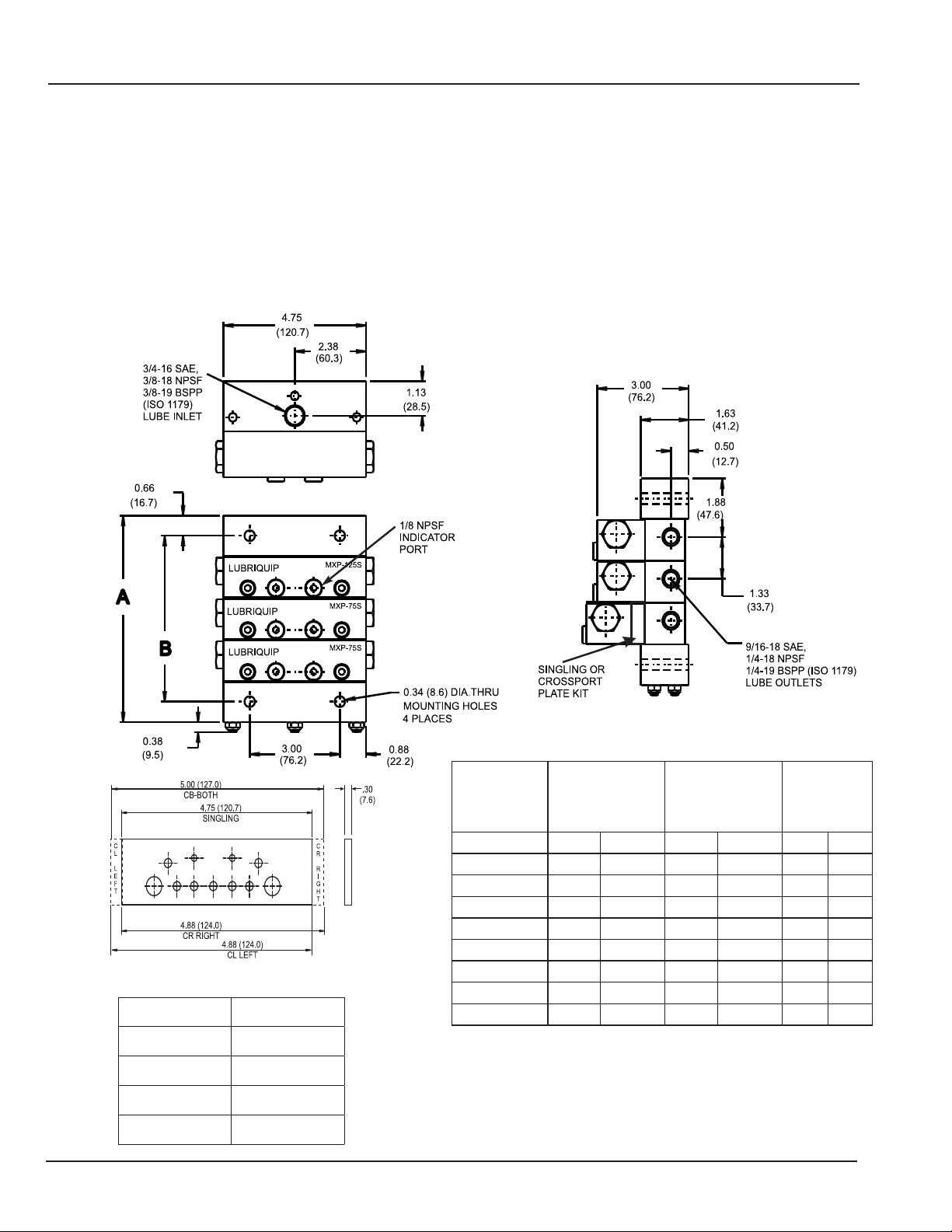
DIMENSIONS
Inches/(mm)
Because the valves are positive displacement, a blocked line
downstream of a valve piston will prevent piston movement and
create high pressure. When performance indicators are used,
the blocked line may be located by identifying which indicator
pin is extended. Pressure switches and relief type performance
indicators and broken line indicators are also available.
PRODUCT I.D.
STYLE TAB(S)
CR RIGHT RIGHT
CL LEFT LEFT
CB-BOTH RIGHT & LEFT
SINGLING NONE
NUMBER OF
SECTIONS
3 6.66 (169.21) 5.35 (135.89) 18.2 8.3
4 8.01 (203.45) 6.70 (170.13) 22.6 10.2
5 9.36 (237.69) 8.05 (204.37) 26.9 12.2
6 10.71 (271.93) 9.39 (238.61) 31.3 14.2
7 12.05 (306.17) 10.74 (272.85) 35.6 16.2
8 13.40 (340.41) 12.09 (307.09) 39.9 18.1
9 14.75 (374.65) 13.44 (341.33) 44.3 20.1
10 16.10 (408.89) 14.79 (375.57) 48.6 22.1
A-DIM B-DIM WEIGHT
Inches (mm) Inches (mm) Lbs (Kg)
Page 2
Page 3

Trabon® Modular MXP Divider Valves
L10132
SPECIFICATION
Material Zinc Plated Steel
O-Ring Seal 90 Durometer Viton
Max Cycle Rate:
w/Cycle Pin 60 CPM
w/o Cycle Pin, or w/ Prox Cycle Sw 200 CPM
Pressure (max) 3,000 psi (207 bar)
Temperature (max) 350ºF (177ºC)
Lubricant Oil or Grease
Torque:
Tie Rod Nut 6-9 ft lbs
Valve Section Mounting Screw 12-13 ft lbs
Indicator Port Plug 12-15 ft lbs
Enclosure Plug 46-50 ft lbs
ACCESSORIES
Description Part No. Old Part No.
Crossport Plate (Left) 563524 527-300-970
Crossport Plate (Right) 563525 527-300-980
Singling Plate – 527-301-000
Indicator Port Adaptor (7/16-20 SAE) – 527-300-851
Outlet Plug 1/4-18 NPTF 557391 508-975-000
Outlet Plug 9/16-18 SAE 556430 412-700-494
Outlet Plug 1/4-19 BSPP 556427 412-700-455
Performance Indicators See bulletin L15401
Accessories and Parts See bulletin L10161
Check Valves See bulletin L15825
Broken Line Indicators See bulletin L15416
Cycle Indicator Proximity Switch See bulletin L15600
DIVIDER VALVE COMPONENT ORDERING INFORMATION
Size Description
25T .025 Twin Outlet .025 .410 562813 106-300-010 – –
25S .025 Single Outlet .050 .820 562819 106-300-070 – –
50T .050 Twin Outlet .050 .820 562814 106-300-020 562825 106-300-130
50S .050 Single Outlet .100 1.639 562820 106-300-080 562830 106-300-180
75T .075 Twin Outlet .075 1.230 562815 106-300-030 562826 106-300-140
75S .075 Single Outlet .150 2.459 562821 106-300-090 562831 106-300-190
100T .100 Twin Outlet .100 1.639 562816 106-300-040 562827 106-300-150
100S .100 Single Outlet .200 3.278 562822 106-300-100 562832 106-300-200
125T .125 Twin Outlet .125 2.049 562817 106-300-050 562828 106-300-160
125S .125 Single Outlet .250 4.098 562823 106-300-110 562833 106-300-210
150T .150 Twin Outlet .150 2.459 562818 106-300-060 562829 106-300-170
150S .150 Single Outlet .300 4.917 562824 106-300-120 562834 106-300-220
B.P. Bypass – – 562835 106-300-410 – –
Inlet (NPSF) 15R993 527-300-000
Inlet (SAE) 15R994 527-300-001
Inlet (BSPP) 561029 527-300-760
Intermediate Base (NPSF) 563519 527-300-100
Intermediate Base (SAE) 563521 527-300-710
Intermediate Base (BSPP) 563522 527-300-740
MXPO Base (NPSF) 563527 527-301-160
MXPO Base (SAE) – 527-301-150
End 563518 527-300-090
*Tie Rod 3 Section 557766 527-300-270
*Tie Rod 4 Section 557767 527-300-280
*Tie Rod 5 Section 557768 527-300-290
*Tie Rod 6 Section 557769 527-300-300
*Tie Rod 7 Section 557770 527-300-310
*Tie Rod 8 Section 557771 527-300-320
*Tie Rod 9 Section 557772 527-300-330
*Tie Rod 10 Section 563520 527-300-340
*Tie Rod Nut 555406 410-440-020
*Three (3) Tie Rods and three (3) Nuts are required per divider assembly
Displacement Per Valve Cycle
cu.in cc
Valve
Section
Part No.
Valve
Section
Old Part No.
w/Cycle Pin
Right Side
Part No.
w/Cycle Pin
Right Side
Old Part No.
Page 3
Page 4

ORDERING INFORMATION
MXP - XXX - X - XX - XXX - X - XX
PORTING OPTIONS
SAE - STRAIGHT THREAD O-RING SEAL
NPT - NPSF PIPE THREAD
BSP - BSPP (ISO 1179)
ACCESSORY OPTIONS*
P - ASSEMBLY OF PERFORMANCE INDICATORS IN
ALL WORKING OUTLETS
*OMIT IF NOT REQUIRED
NUMBER OF SECTIONS
03 - THREE 07 - SEVEN
04 - FOUR 08 - EIGHT
05 - FIVE 09 - NINE
06 - SIX 10 - TEN
VALVE CAPACITY
BP - BYPASS 100 - .100 cu.in.
25 - .025 cu.in. 125 - .125 cu.in.
50 - .050 cu.in. 150 - .150 cu.in.
75 - .075 cu.in.
TYPE OF SECTION
T - TWIN STANDARD
S - SINGLE STANDARD - RH OUTLET
L - SINGLE STANDARD - LH OUTLET
B - TWIN W/CYCLE PIN RIGHT SIDE
C - SINGLE W/CYCLE PIN RIGHT SIDE - RH OUTLET
D - SINGLE W/CYCLE PIN RIGHT SIDE - LH OUTLET
CROSSPORTING OPTIONS
CR - RIGHT HAND SIDE
CL - LEFT HAND SIDE
CB - BOTH SIDES
NOTES:
1. Capacity sections are specifi ed starting from inlet
section and must equal number of manifold sections
in subplate.
2. When capacity section is crossported, its outlet is
plugged and the output volume is diverted to next
section, farthest from inlet section.
3. Last capacity section, farthest from inlet, cannot be
crossported.
4. Single output capacity sections can be crossported
on one side only.
5. All crossporting is accomplished external using the
crossport kits listed on page 3.
6. When capacity section is singled, only one outlet
in its subplate can be used. Other outlet must be
plugged.
7. By-pass block cannot be supplied on a three section
assembly; all manifolded assemblies must have a
minimum of three working capacity sections.
8. Contact Graco for part numbers of stainless steel
components
9. Divider Systems should be limited to fi rst and second
stages only. Third staging is not recommended.
Refer to Trabon® bulletin L20101, L20105 and
L20115 for further information on system design.
Ordering Example
5 section MXP divider valve with SAE ports and performance indicators
in each working outlet consisting of:
1-100 Twin Valve w/Cycle Pin Right Side
1-150 Single Valve Crossport Right Side
1-150 Single Valve Right Side Outlet
1-125 Twin Valve
1-Bypass Section
Order Code: MSP-SAE-P-5-100B-150SCR-150S-125T-BP
Graco endorses the SAE recommendation of ISO 18/14 (ISO 4406) oil cleanliness
for most bearing applications. Some high speed bearings may require cleaner oil.
Consult the bearing manufacturer for recommendation.
All written and visual data contained in this document are based on the latest product information available at the time of publication. Graco reserves the right to make changes at any time without notice.
Contact us today!
To receive product information or talk with a Graco representative,
call 800-533-9655 or visit us online at www.graco.com.
©2006-2009 Graco Inc. Form No. L10132 Rev. B 1/09 Printed in U.S.A. All other brand names or marks are used for identification purposes and are trademarks of their respective owners. All written and
visual data contained in this document are based on the latest product information available at the time of publication. Graco reserves the right to make changes at any time without notice.
 Loading...