

Page 1
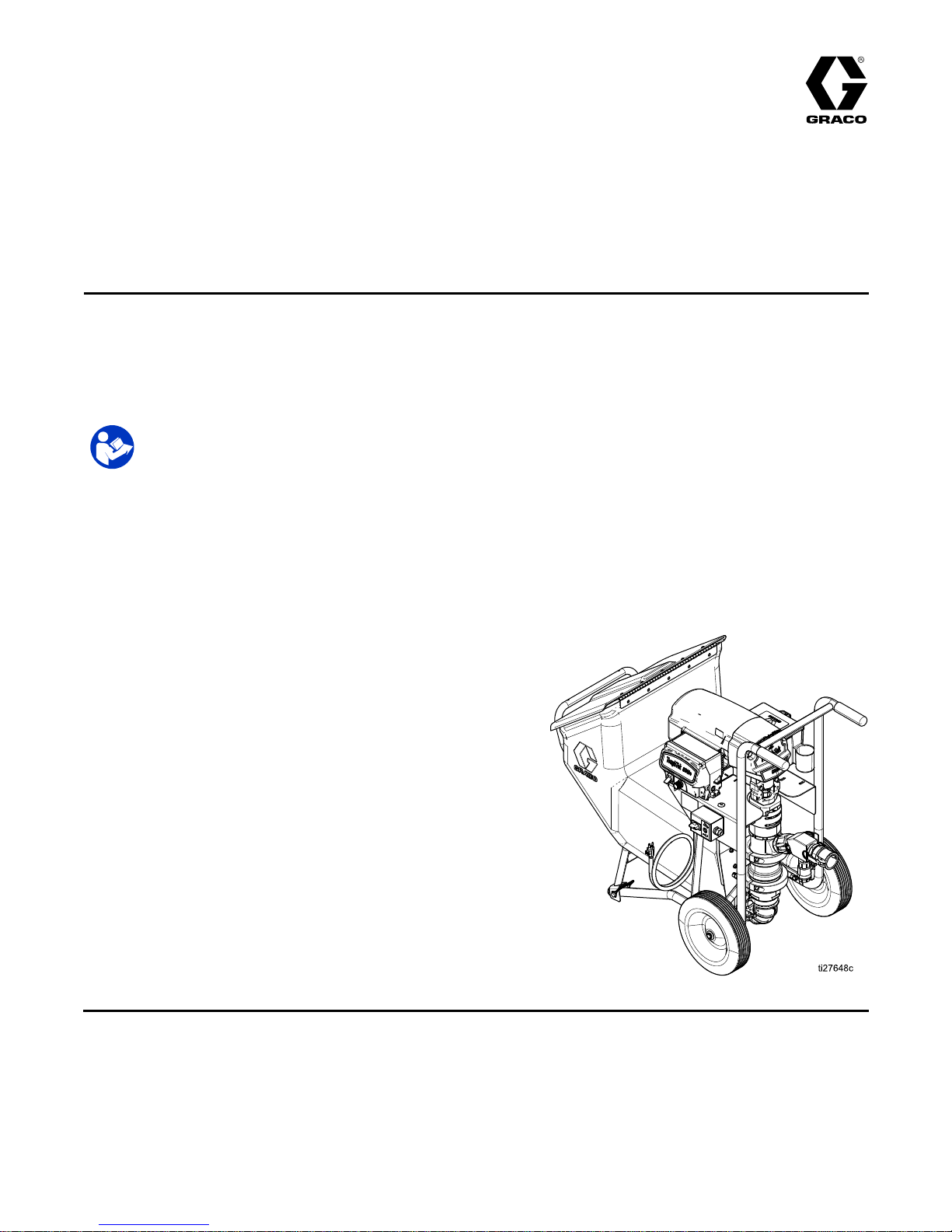
Operation,Repair,andParts
ToughTek® ToughTek®
ToughTek®
S340e S340e
S340e
Portable Portable
Portable
Stucco Stucco
Stucco
Pump Pump
Pump
3A3437F
EN
Electric Electric
Electric
sprayer sprayer
sprayer
for for
for
water water
water
- --based based
based
stucco stucco
stucco
base, base,
base,
nish nish
nish
coat coat
coat
materials, materials,
materials,
and and
and
Exterior Exterior
Exterior
Insulation Insulation
Insulation
and and
and
Finish Finish
Finish
Systems Systems
Systems
(EIFS). (EIFS).
(EIFS).
For For
For
professional professional
professional
use use
use
only. only.
only.
Not Not
Not
approved approved
approved
for for
for
use use
use
in ininexplosive explosive
explosive
atmospheres atmospheres
atmospheres
or or
or
hazardous hazardous
hazardous
locations. locations.
locations.
Important Important
Important
Safety Safety
Safety
Instructions Instructions
Instructions
Readallwarningsandinstructionsinthismanualandinrelated
manuals.Save Save
Save
these these
these
instructions. instructions.
instructions.
For models and related manuals, see
page 3.
600 psi (4.13 MPa, 41.3 bar) Maximum
Fluid Working Pressure
PROVENQUALITY.LEADINGTECHNOLOGY.
Page 2

Contents Contents
Contents
Models...............................................................3
RelatedManuals................................................3
ReplacementPartsandAccessories....................4
Warnings...........................................................6
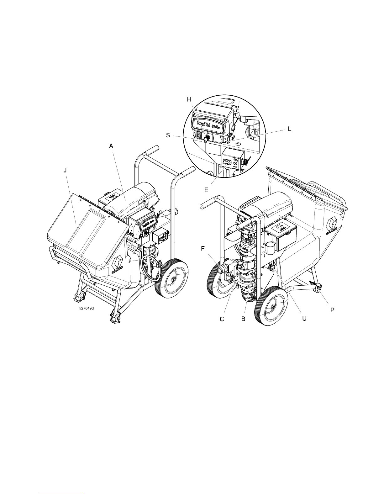
ComponentIdentication.....................................9
Overview.....................................................9
ComponentIdenticationTable.....................9
MotorPowerSwitch.....................................10
ConnectHosesandApplicator......................10
InstalltheRemoteSwitch(Optional)..............11
PrimewithMaterial......................................11
Grounding..........................................................12
PowerRequirements..........................................12
Setup.................................................................13
Flush.................................................................14
PrimewithWater................................................16
MixtheMaterial..................................................17
PrimewithMaterial.............................................17
Spray.................................................................18
PreventPack-out.........................................18
BeforeStartingorStoppingMaterial
Flow..............................................18
Spraying......................................................18
SprayAdjustments(PoleSprayApplicator)...........19
GeneralAdjustments....................................19
SprayingTechniques....................................19
MaterialFlowAdjustment.............................19
AirFlowValveAdjustment............................19
InstallingNozzleRetainingCap.....................19
SprayAdjustments(HTXTMApplicator)...............20
FluidDrain/PurgeValve......................................21
PressureReliefProcedure..................................21
HopperRemoval................................................22
Shutdown...........................................................22
LiftingInstructions...............................................22
Maintenance......................................................23
DailyMaintenance.......................................23
PreventativeMaintenance............................23
CorrosionProtection....................................23
WaterExposure...........................................23
Troubleshooting..................................................24
Mechanical/FluidFlow..................................24
Electrical.....................................................25
Repair................................................................27
ReplacePumpLower...................................27
Parts..................................................................30
TechnicalSpecications......................................37
GracoStandardWarranty....................................38
2
3A3437F
Page 3
Models
Models Models
Models
Bare Bare
Bare
Model Model
Model
Electric Electric
Electric
Requirements Requirements
Requirements
Approval Approval
Approval
Country Country
Country
Remote Remote
Remote
On/Off On/Off
On/Off
Switch Switch
Switch
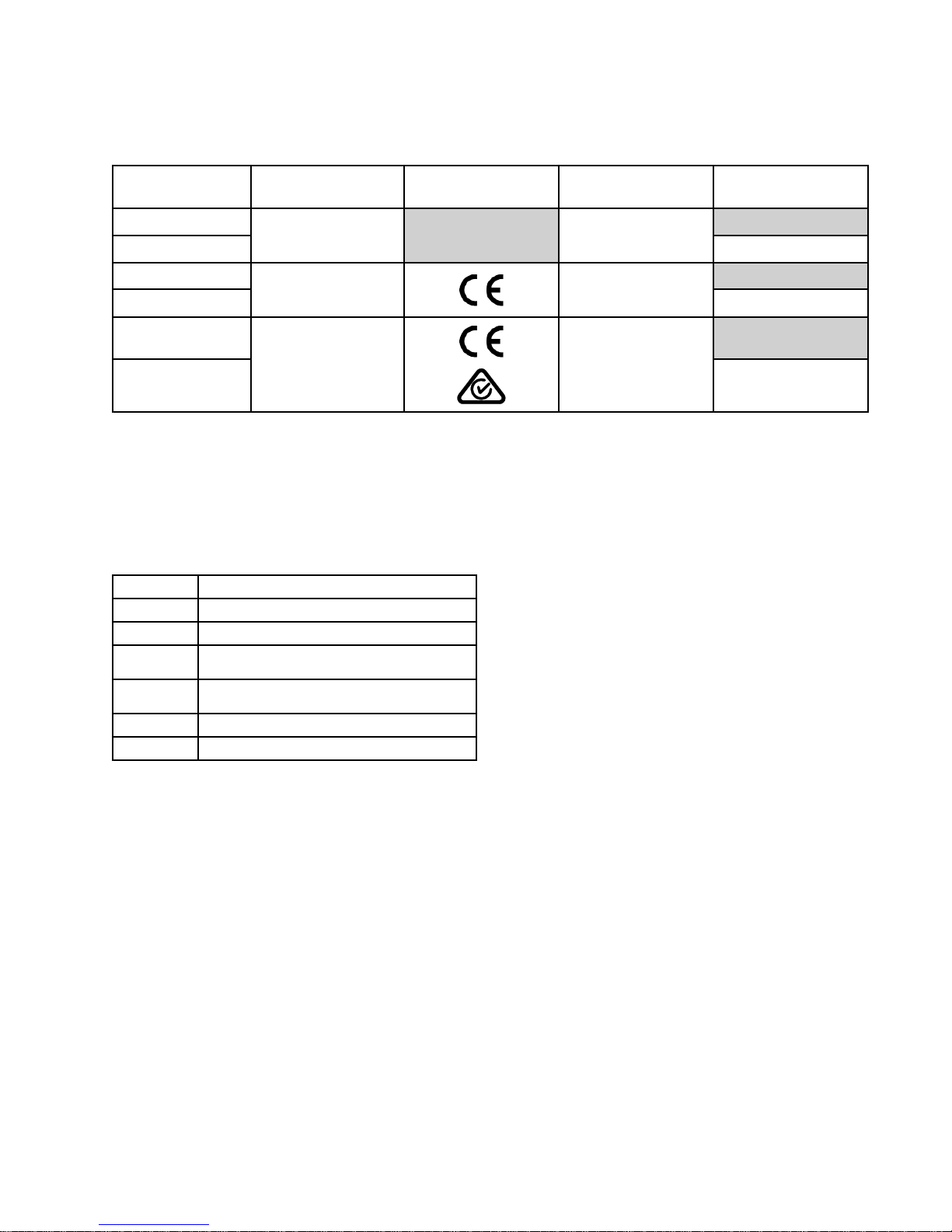
25A300
25A302
120V,15A,50/60
Hz,1Ф
NorthAmerica
✔
25C610
25C612
120V,15A,50/60
Hz,1Ф
UnitedKingdom
✔
25A304†
25A306†
230V,10A,50/60
Hz,1Ф
Europe,Asia,
Australia
✔
†
All 230V pumps include a Europe adapter and Australia adapter cord set.
Related Related
Related
Manuals Manuals
Manuals
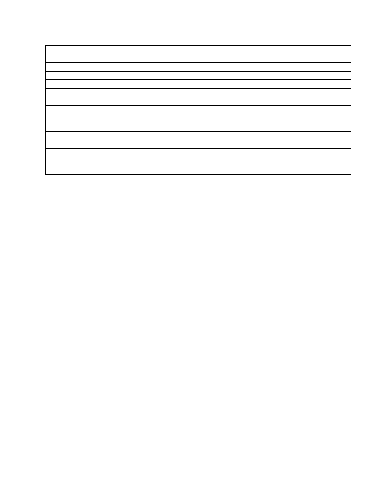
Manualsareavailableatwww.graco.com.
ComponentmanualsinEnglish:
Manual Manual
Manual
Description Description
Description
3A3438
PoleSprayApplicator
3A3653
HTXFinishCoatApplicator
3A3112
ToughTek®F340eRemoteSwitch
AccessoryKit17G554
3A3439
ToughTek®S340ePumpLower
ConversionKit
3A5637
ToughTek®CamlockMortarHose
3A4554
ToughTek®MortarCouplingHose
3A3437F 3
Page 4

ReplacementPartsandAccessories
Replacement Replacement
Replacement
Parts Parts
Parts
and and
and
Accessories Accessories
Accessories
Accessories Accessories
Accessories
17G554
KIT,remoteswitch
17W604
KIT,remoteswitch,cable(switchand100ftcable)
17W829
KIT,remoteswitch,extensioncord(110ft)
248515
KIT,spongeball,30mmfor25mm(1.0in.)dia.hose(Qty.5)
25A227
KIT,spongeball,40mmfor35mm(1–3/8in.)dia.hose(Qty.5)
17G930KIT,spongeball,60mmfor50mm(2in.)dia.hose(Qty.5)
114271
STRAP,retaining
240296KIT,retainingstraps,4–pack
118665
TUBE,grease,FusionGun,4oz.
248279
TUBE,grease,FusionGun,4oz.,10–pack
206994
FLUID,TSL8oz.bottle
Lower Lower
Lower
Assembly Assembly
Assembly
25A233KIT,rebuild,pump
17G456
KIT,lower,clamp
16W490KIT,repair,10–pack,o-ring,cylinderend
25A467KIT,repair,checkballs
17G865
KIT,repair,3–pack,seal,throat,triplelip
17G864KIT,pumplower,S340e
25A178
KIT,conversion,F340etoS340e
Inlet Inlet
Inlet
17G863
KIT,repair,seat,inlet
15H833BALL,neo/sstcore1.75in.
Piston Piston
Piston
17G862
KIT,repair,seat,piston
17G798
BALL,neoprene,cscore,1.625in.
16W491KIT,repair,3–pack,seal,piston
Check Check
Check
Valve Valve
Valve
25A466
KIT,outlet,checkvalve,S340
17H192KIT,outlet,seat,o-ring
113082
PACKING,o-ring
17H194KIT,outlet,check,valve
102973BALL,metallic
17J712KIT,F340e,check,retainer
17G866KIT,tting,cam,checkvalve
Rubber Rubber
Rubber
Elbow Elbow
Elbow
17H193KIT,inlet,elbow
17H196KIT,elbow,bandclamp
4
3A3437F
Page 5
ReplacementPartsandAccessories
Hopper Hopper
Hopper
17J707KIT,F340e,hopperwithcover
17J709KIT,F340e,hopper,bracket
17J812KIT,F340e,stop,bracket
17J710KIT,F340e,adjustablelatch
17J708KIT,F340e,stop,brackets
Motor Motor
Motor
and and
and
Driver Driver
Driver
17J702
KIT,F340e,MCM,120V
25C512KIT,F340e,MCM,120V,UK
17J755
KIT,F340e,MCM,230V
17J711KIT,F340e,motor
17J714
KIT,F340e,nger,guard
17J704
KIT,F340e,front,cover
287282KIT,repair,shield,motor
17J705KIT,F340e,toolbox
3A3437F 5
Page 6
Warnings
Warnings Warnings
Warnings
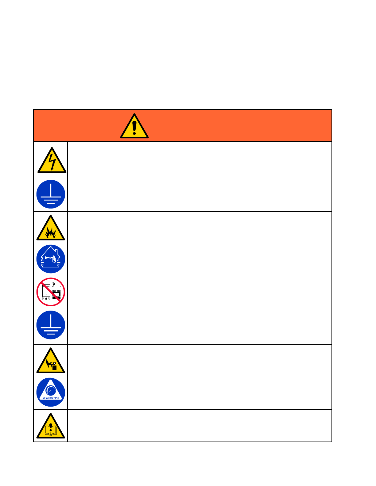
Thefollowingwarningsareforthesetup,use,grounding,maintenance,andrepairofthisequipment.The
exclamationpointsymbolalertsyoutoageneralwarningandthehazardsymbolsrefertoprocedure-specic
risks.Whenthesesymbolsappearinthebodyofthismanualoronwarninglabels,referbacktothese
Warnings.Product-specichazardsymbolsandwarningsnotcoveredinthissectionmayappearthroughout
thebodyofthismanualwhereapplicable.
WARNING WARNING
WARNING
ELECTRIC ELECTRIC
ELECTRIC
SHOCK SHOCK
SHOCK
HAZARD HAZARD
HAZARD
Thisequipmentmustbegrounded.Impropergrounding,setup,orusageofthesystemcan
causeelectricshock.
•Turnoffanddisconnectpowercordbeforeservicingequipment.
•Connectonlytogroundedelectricaloutlets.
•Useonly3–wireextensioncords.
•Ensuregroundprongsareintactonpowerandextensioncords.
•Donotexposetorain.Storeindoors.
FIRE FIRE
FIRE
AND AND
AND
EXPLOSION EXPLOSION
EXPLOSION
HAZARD HAZARD
HAZARD
Flammablefumes,suchassolventandpaintfumes,inwork work
work
area area
area
canigniteorexplode.Tohelp
preventreandexplosion:
•Useequipmentonlyinwellventilatedarea.
•Eliminateallignitionsources;suchaspilotlights,cigarettes,portableelectriclamps,and
plasticdropcloths(potentialstaticsparking).
•Groundallequipmentintheworkarea.SeeGrounding Grounding
Grounding
instructions.
•Keepworkareafreeofdebris,includingsolvent,ragsandgasoline.
•Neversprayorushsolventathighpressure.
•Donotplugorunplugpowercords,orturnpowerorlightswitchesonoroffwhenammable
fumesarepresent.
•Useonlygroundedhoses.
•Holdapplicatorrmlytosideofgroundedpailwhentriggeringintopail.Donotusepail
linersunlesstheyareantistaticorconductive.
•Stop Stop
Stop
operation operation
operation
immediately immediately
immediately
ifstaticsparkingoccursoryoufeelashock. ..Donotuse
equipmentuntilyouidentifyandcorrecttheproblem.
•Keepaworkingreextinguisherintheworkarea.
MOVING MOVING
MOVING
PARTS PARTS
PARTS
HAZARD HAZARD
HAZARD
Movingpartscanpinch,cutoramputatengersandotherbodyparts.
•Keepclearofmovingparts.
•Donotoperateequipmentwithprotectiveguardsorcoversremoved.
•Pressurizedequipmentcanstartwithoutwarning.Beforechecking,moving,orservicing
equipment,followthePressure Pressure
Pressure
Relief Relief
Relief
Procedure Procedure
Procedure
anddisconnectallpowersources.
SUCTION SUCTION
SUCTION
HAZARD HAZARD
HAZARD
Powerfulsuctioncouldcauseseriousinjury.
•Neverplacehandsnearthepumpuidinletwhenpumpisoperatingorpressurized.
6 3A3437F
Page 7
Warnings
WARNING WARNING
WARNING
EQUIPMENT EQUIPMENT
EQUIPMENT
MISUSE MISUSE
MISUSE
HAZARD HAZARD
HAZARD
Misusecancausedeathorseriousinjury.
•Donotoperatetheunitwhenfatiguedorundertheinuenceofdrugsoralcohol.
•Donotexceedthemaximumworkingpressureortemperatureratingofthelowestrated
systemcomponent.SeeTechnical Technical
Technical
Data Data
Data
inallequipmentmanuals.
•Useuidsandsolventsthatarecompatiblewithequipmentwettedparts.SeeTechnicalData
inallequipmentmanuals.Readuidandsolventmanufacturer’swarnings.Forcomplete
informationaboutyourmaterial,requestSafetyDataSheets(SDSs)fromdistributoror
retailer.
•Donotleavetheworkareawhileequipmentisenergizedorunderpressure.
•TurnoffallequipmentandfollowthePressure Pressure
Pressure
Relief Relief
Relief
Procedure Procedure
Procedure
whenequipmentisnotinuse.
•Checkequipmentdaily.Repairorreplacewornordamagedpartsimmediatelywithgenuine
manufacturer’sreplacementpartsonly.
•Donotalterormodifyequipment.Alterationsormodicationsmayvoidagencyapprovals
andcreatesafetyhazards.
•Makesureallequipmentisratedandapprovedfortheenvironmentinwhichyouareusingit.
•Useequipmentonlyforitsintendedpurpose.Callyourdistributorforinformation.
•Routehosesandcablesawayfromtrafcareas,sharpedges,movingparts,andhotsurfaces.
•Donotkinkoroverbendhosesorusehosestopullequipment.
•Keepchildrenandanimalsawayfromworkarea.
•Complywithallapplicablesafetyregulations.
PRESSURIZED PRESSURIZED
PRESSURIZED
ALUMINUM ALUMINUM
ALUMINUM
PARTS PARTS
PARTS
HAZARD HAZARD
HAZARD
Useofuidsthatareincompatiblewithaluminuminpressurizedequipmentcancauseserious
chemicalreactionandequipmentrupture.Failuretofollowthiswarningcanresultindeath,
seriousinjury,orpropertydamage.
•Donotuse1,1,1-trichloroethane,methylenechloride,otherhalogenatedhydrocarbon
solventsoruidscontainingsuchsolvents.
•Donotusechlorinebleach.
•Manyotheruidsmaycontainchemicalsthatcanreactwithaluminum.Contactyourmaterial
supplierforcompatibility.
3A3437F
7
Page 8
Warnings
WARNING WARNING
WARNING
SKIN SKIN
SKIN
INJECTION INJECTION
INJECTION
HAZARD HAZARD
HAZARD
High-pressureuidfromdispensingdevice,hoseleaks,orrupturedcomponentswillpierce
skin.Thismaylooklikejustacut,butitisaseriousinjurythatcanresultinamputation.Get Get
Get
immediate immediate
immediate
surgical surgical
surgical
treatment. treatment.
treatment.
•Donotpointdispensingdeviceatanyoneoratanypartofthebody.
•Donotputyourhandovertheuidoutlet.
•Donotstopordeectleakswithyourhand,body,glove,orrag.
•FollowthePressure Pressure
Pressure
Relief Relief
Relief
Procedure Procedure
Procedure
whenyoustopdispensingandbeforecleaning,
checking,orservicingequipment.
•Tightenalluidconnectionsbeforeoperatingtheequipment.
•Checkhosesandcouplingsdaily.Replacewornordamagedpartsimmediately.
TOXIC TOXIC
TOXIC
FLUID FLUID
FLUID
OR OR
OR
FUMES FUMES
FUMES
HAZARD HAZARD
HAZARD
Toxicuidsorfumescancauseseriousinjuryordeathifsplashedintheeyesoronskin,
inhaled,orswallowed.
•ReadSafetyDataSheets(SDSs)toknowthespecichazardsoftheuidsyouareusing.
•Storehazardousuidinapprovedcontainers,anddisposeofitaccordingtoapplicable
guidelines.
PERSONAL PERSONAL
PERSONAL
PROTECTIVE PROTECTIVE
PROTECTIVE
EQUIPMENT EQUIPMENT
EQUIPMENT
Wearappropriateprotectiveequipmentwhenintheworkareatohelppreventseriousinjury,
includingeyeinjury,hearingloss,inhalationoftoxicfumes,andburns.Protectiveequipment
includesbutisnotlimitedto:
•Protectiveeyewear,andhearingprotection.
•Respirators,protectiveclothing,andglovesasrecommendedbytheuidandsolvent
manufacturer.
8 3A3437F
Page 9
ComponentIdentication
Component Component
Component
Identication Identication
Identication
Overview Overview
Overview
Component Component
Component
Identication Identication
Identication
Table Table
Table
Key: Key:
Key:
AElectricMotor
BPumpLower
C
FluidDrain/PurgeValve
E
RemotePumpControlSwitch(optional)
F
FluidOutlet
HFlowAdjustmentKnob
JHopper
L
ControlBoardStatusLight
Key: Key:
Key:
PHopperPin
SMotorPowerSwitch
UHopperLatch
3A3437F 9
Page 10

ComponentIdentication
Motor Motor
Motor
Power Power
Power
Switch Switch
Switch
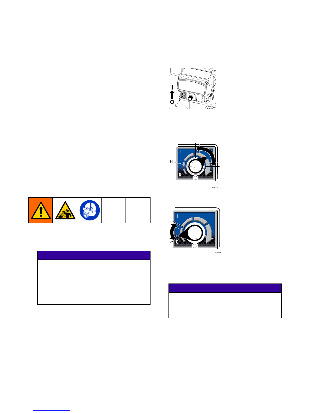
Themotorpowerswitch(S)mustbeintheONforthe
sprayertopumpmaterial.
Motor Motor
Motor
Power Power
Power
Switch Switch
Switch
Settings: Settings:
Settings:
OFFPowerisoff.Themotorwillnotrun.
ON
Themotorwillruncontinuouslyat
aspeeddeterminedbytheow
adjustmentknob.
Connect Connect
Connect
Hoses Hoses
Hoses
and and
and
Applicator Applicator
Applicator
•Beforeconnectinghoses/applicator,inspectfor
damageorweartoboththehose/applicatorand
camlockttings.Fittingsshouldbecleanandfree
ofdebris,dents,cracksornicks.Thefemalecam
lockttingmusthavethegasketinstalled.
•Alwaysconnecthosesfromlargestdiameterto
smallestdiameter.
•Useaminimumof25ftofhosewithaworking
pressureofatleast600psi(4.1MPa,41bar).
•Whenfasteningcamlocks,makesurethepullring
staystotheoutsideofthecamlockarmtoallow
forcompleteandpropersealingofthecamlock.
Onceinstalled,useVelcrostrapstosecurecam
locksinplace.
10 3A3437F
Page 11
ComponentIdentication
Install Install
Install
the the
the
Remote Remote
Remote
Switch Switch
Switch
(Optional) (Optional)
(Optional)
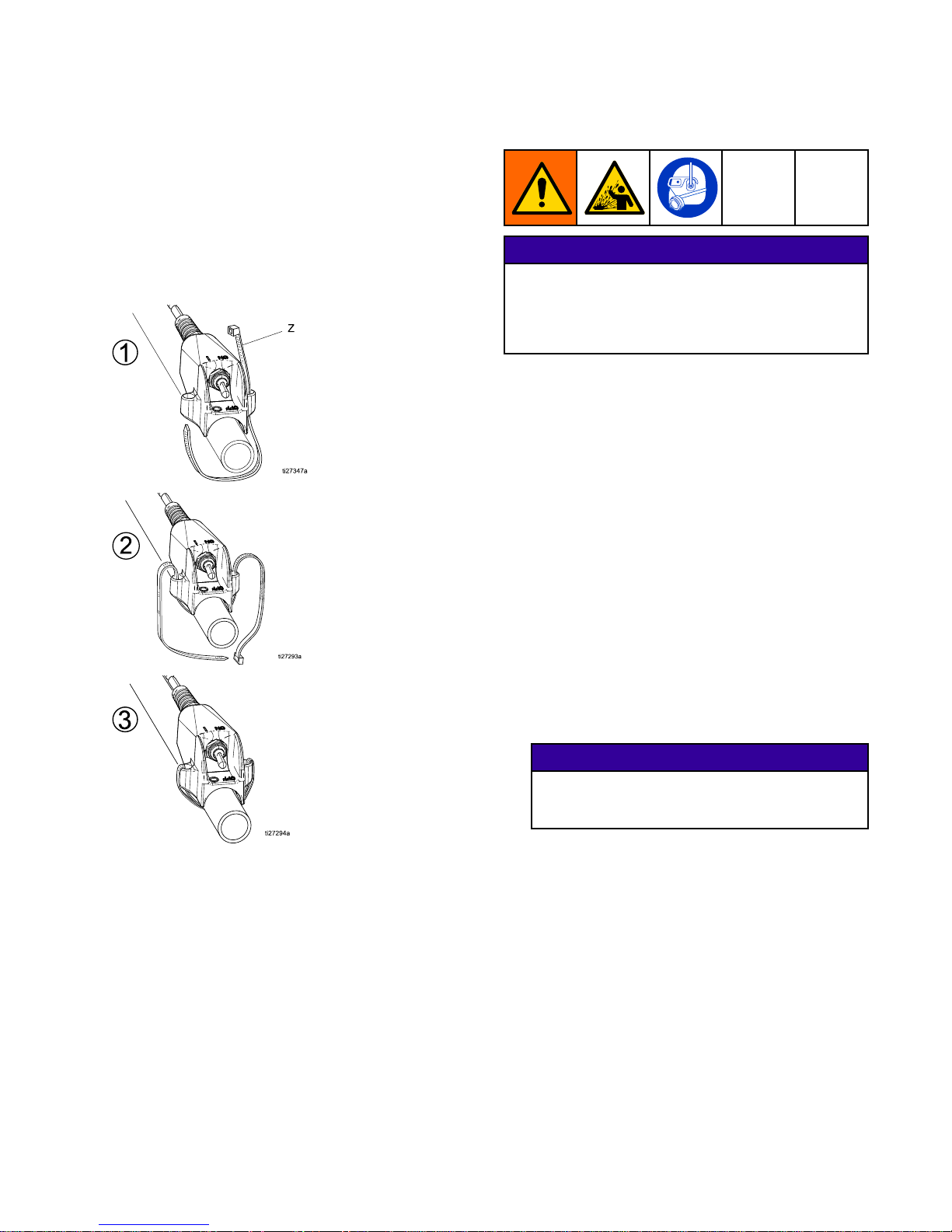
Theremoteswitchisanadditionalaccessorykitand
doesnotcomewithmodels25A300and25A304.
Thekitpartnumberis17G554.Seemanual3A3112
forremoteswitchinstallationandreplacement.
NOTE: NOTE:
NOTE:
Usezip-tie(Z)toinstalltheremoteswitch
tothehoseorpolesprayapplicator(followthe
illustrationsbelow).Theremoteswitchwillton
hoses/applicatorssized.75in.upto1.25in.
Prime Prime
Prime
with with
with
Material Material
Material
NOTICE NOTICE
NOTICE
Loadingmaterialintoadrysystemwillcausethematerial
tosticktointernalcomponentsandcure,causing
damageandrequiringreplacementofthoseparts.To
preventmaterialcuringinsystem,neverloadmaterial
intoadrysystem.
Theapplicatormustberemovedbeforepriming.
Alwayspushoutanyremainingwaterintoawaste
containerbeforecirculatingmaterial.Alwayscirculate
cleanmaterialbackintothehopperforseveralcycles
beforebeginningtospray.
1.Primethesystemwithwater.See
PrimewithWater,page16.
2.Mixthematerial.SeeMixtheMaterial,page17.
3.Turntheowadjustmentknob(H)
counterclockwiseuntilitstops.
4.Removetheapplicator.
5.Fillthecleanhopperwithmaterialtobesprayed.
6.Placethehoseoutletinawastecontainer.
7.Turnthemotorpowerswitch(S)toON.
8.Turntheowadjustmentknob(H)clockwise
slowlytoincreasepressureuntilwaterispurged
outandasteadystreamofmaterialowsfrom
theapplicator.
NOTICE NOTICE
NOTICE
Topreventdamagetopumpsealscausedby
cavitation,runthepumpslowlyuntilthesystemis
primed.
9.Tostopdispensing,turnadjustmentknob(H)
counterclockwiseuntilitstops.
10.Installapplicator.
NOTE: NOTE:
NOTE:
ForEIFSnishcoats,beforeinstallingthe
applicator,primethelargerIDhose,theninstall
andprimethetransitionttingandwhiphose.
11.Recirculateseveralcyclesofmaterialtomake
surethematerialisowingproperly.
12.Turntheowadjustmentknob(H)
counterclockwisetostopthepump.
13.Installtheairlineandatipontotheapplicator
(seeapplicatormanual).Thesystemisnow
primedandreadytospray.
3A3437F
11
Page 12
Grounding
Grounding Grounding
Grounding
Theequipmentmustbegroundedtoreducethe
riskofstaticsparkingandelectricshock.Electric
orstaticsparkingcancausefumestoigniteor
explode.Impropergroundingcancauseelectric
shock.Groundingprovidesanescapewireforthe
electriccurrent.
Groundthesprayerbypluggingitintoanoutletthat
isproperlyinstalledandgroundedinaccordancewith
alllocalcodesandordinances.Donotmodifythe
powercordprovided;ifitdoesnotttheoutlet,have
theproperoutletinstalledbyaqualiedelectrician.
Extension Extension
Extension
Cords Cords
Cords
•Useonlya3-wireextensioncordthathasa
groundingplugandagroundingreceptaclethat
acceptstheplugontheproduct.
•Makesureyourextensioncordisnotdamaged.
•Ifanextensioncordisnecessary,use12AWG(2.5
mm
2
)minimumtocarrythecurrentthattheproduct
draws.Anundersizedextensioncordresultsina
dropinlinevoltage,lossofpower,andoverheating.
NOTE: NOTE:
NOTE:
CertainGFCIoutletshavebeenknowntotrip
whileusingthisproduct.
For120Vunits,useadedicated15ampcircuit.
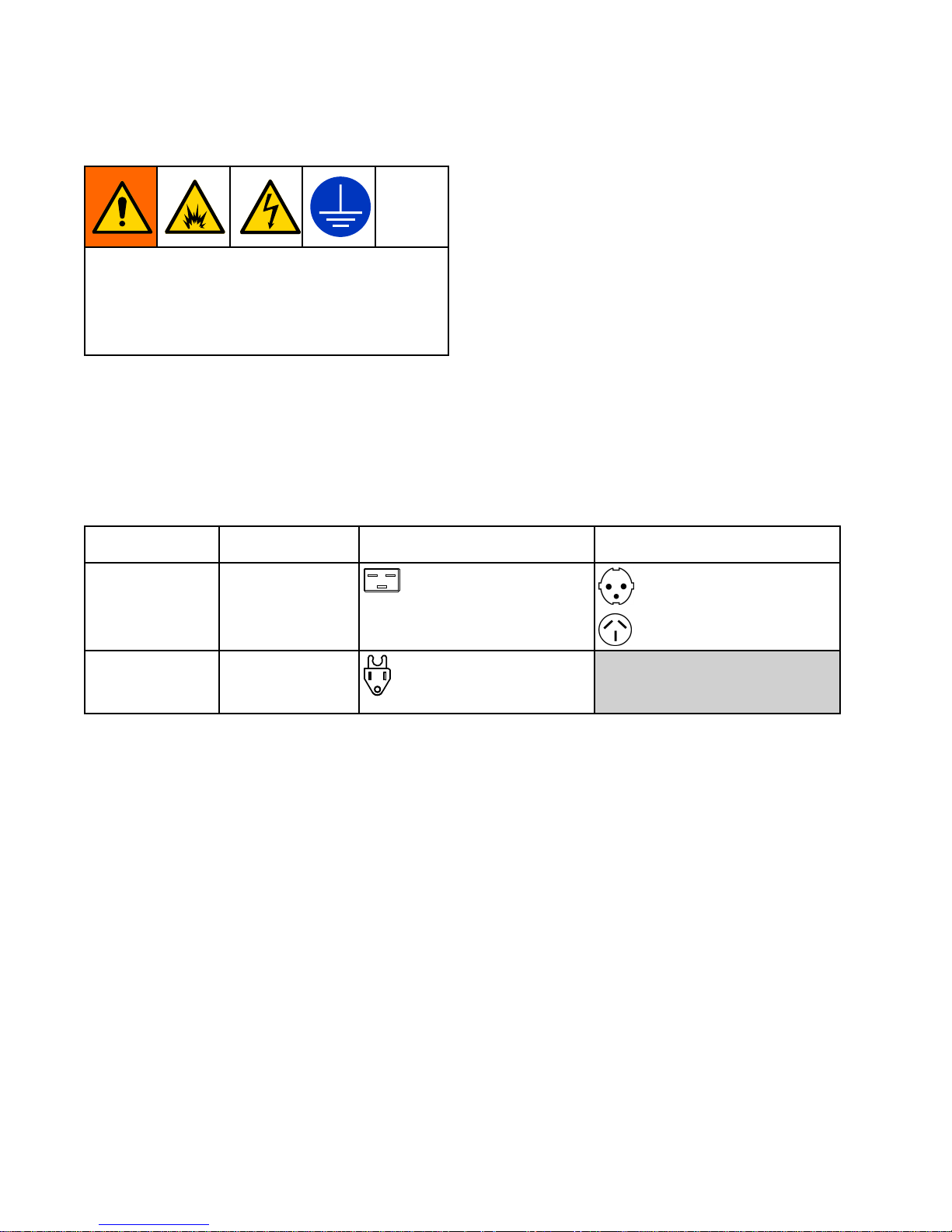
Power Power
Power
Requirements Requirements
Requirements
Model Model
Model
Required Required
Required
Power Power
Power
Source Source
Source
Power Power
Power
Cord Cord
Cord
Connectors Connectors
Connectors
Supplied Supplied
Supplied
Local Local
Local
Adapters Adapters
Adapters
EuroCEE7(Europe)
230V,1phase,
50/60Hz
Oneseparate
dedicatedcircuit
ratedatminimumof
10A
OneIEC3-20C20Plugs
AS/NZS(Australia)
120V,50/60Hz
Oneseparate
dedicatedcircuit
ratedatminimumof
15A
OneNEMA5–15APlug
12
3A3437F
Page 13
Setup
Setup Setup
Setup
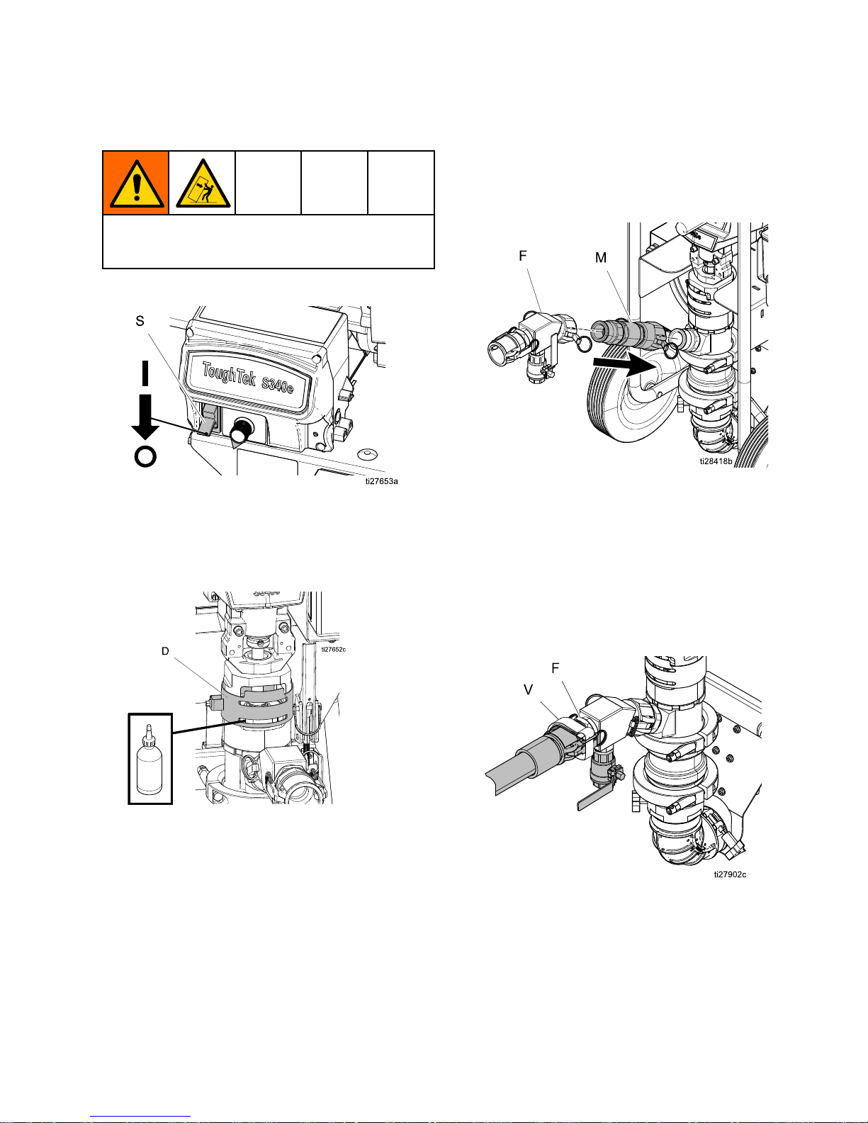
Toavoidtippingover,ensurecartisonaatand
levelsurface.Failuretodosocouldresultininjury
orequipmentdamage.
1.Turnthemotorpowerswitch(S)toOFF.
2.Groundsprayer(seeGrounding,page12).Plug
thepowercordintoadedicatedcircuit.See
PowerRequirements,page12.
3.CheckThroatSealLiquid(TSL)levelinpacking
nut(D).Fill1/2fullwithTSL.
4.Connectairsupplytoapplicator.
5.Attachcheckvalve(optional).Removeuid
outletassembly(F).Attachcheckvalve(M)to
pumpuidoutlet.Attachuidoutletassemblyto
checkvalve(M)outlet.
NOTE: NOTE:
NOTE:
Ifacheckvalve(M)isbeingused,itmust
beinstalledbetweentheuidoutletassembly(F)
andthepumplowertoensureproperoperation
ofthepressurereliefvalve.
NOTE: NOTE:
NOTE:
Checkvalve(M)isintendedforuse
withlowviscosityuidssuchaswaterresistive
barriers.
6.Attachhosetoapplicatoruidinletandpump
uidoutlet(F),thensecureVelcrostraps(V)
aroundthecamtting.
7.Primethesystemwithwaterbeforeusing(see
PrimewithWater,page16).
3A3437F 13
Page 14
Flush
Flush Flush
Flush
NOTICE NOTICE
NOTICE
Failuretoushpriortomaterialcuringinthe
systemwillresultindamagetosystemandmay
requirereplacementofallsystempartsincontact
withthematerial.
NOTICE NOTICE
NOTICE
Theuid/drainpurgevalvemustbeushedto
preventmaterialhardeninginuid/drainpurge
valve.Ifthatisnotsufcient,remove,disassemble,
andcleanthevalvethenreinstall.
•Flushifthematerialsinthesystemareaboutto
reachtheircuretime.
•Flushanytimetheowratestartstodecreaseand
therearenoclogsinthesystem,asthisisasign
thatthematerialisstartingtothickenandcure.
•Alwaysushthesystematleasttwice,drainingall
waterbetweenushesthenreplacingwithclean
water.
•Flushusingwateronly.
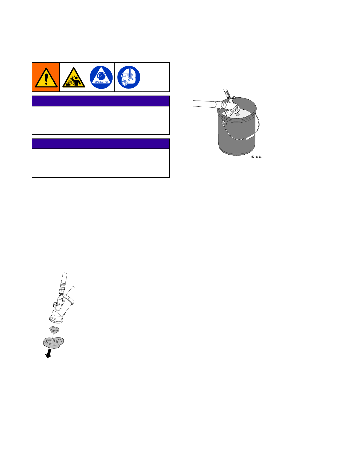
1.PerformPressureReliefProcedure,page21.
2.Removeapplicatortipandretainer.
3.Placeapplicatoroutletinawastecontainer.The
wastecontainermustbelargeenoughtohold
alldispensedmaterial.
ti2
1632a
4.Turnmotorpowerswitch(S)on.
5.Turnadjustmentknob(H)clockwiseslowlyto
increasepressure,untilasteadystreamows
fromgun.
6.Whenthemateriallevelinthehopperiswithina
fewinchesofthematerialinletatthebottom:
a.Scrapethematerialdownthesidesofthe
hopper.
b.Fillthehopperwithwaterasthematerial
runsoutandcontinuedispensing.
c.Scrubthewallsofthehopperwithascrub
brush.
7.Whenwaterbeginstoexittheapplicatoroutlet,
increasetheowadjustmentknobtoushheavy
sedimentsfromthesystem.
8.Onceheavysedimenthasbeenushed,pump
theremainingcontaminatedwateroutofthe
hopper.
9.Turnthemotorpowerswitch(S)OFF.
10.Removethehopperandhopperelbow.
Cleanallresidualmaterial,thenre-install
theelbowandhopperontothesystem.See
HopperRemoval,page22.
14
3A3437F
Page 15

Flush
11.Circulatecleanwater:
a.Fillthesystemhopperwithcleanwater.
b.Turnthemotorpowerswitch(S)toONto
begincirculatingwater.Increaseowand
pumpforseveralcycles.
c.Whilepumping,opentheuiddrain/purge
valve.Allowthewatertoushoutany
materialtopreventmaterialhardeninginthe
valve.Oncethewaterappearsclean,close
theuiddrain/purgevalve.
d.Turnthemotorpowerswitch(S)toOFF.
12.Removetheapplicatorandclean/ush
separately.
a.Makesureallpartsarefreeofresidual
material.
b.Turnonairtomakesureairlinesarefree
ofobstructions.
13.Removetheremainingmaterialwithahose
clean-outball:
a.Placethehoseoutletbackinthewaste
container.
b.Removethehoseinletfromthepumpoutlet
andplaceahoseclean-outballwithinthe
hoseinlet.Theballmustbewetteddown
beforeinserting.Ifusinga1in.whiphose,
beginwiththesmallestclean-outball.
c.Reattachthehosetothepumpoutletand
turnthemotorpowerswitch(S)toONto
resumeushingthehose.
d.Thehoseclean-outballwillbepushedoutof
thehoseafterseveralminutes.Oncetheball
ispushedthroughthehose,turnthemotor
powerswitch(S)toOFF.Repeatuntilall
sedimentisremovedfromthehose.
NOTICE NOTICE
NOTICE
Materialleftonthethroatsealcandryoutand
damagetheseal.Alwaysstopthepumpat
thebottomofthestroketoavoiddamageto
thethroatseal.
e.Ifusinga1in.whiphose,removethe
hoseandtransitionttingandrepeatthe
processusingthelargeclean-outballonthe
remaininghoses.Oncetheballispushed
out,pumpouttheremainingwaterinthe
hopper,thenreattachthetransitiontting
andwhiphose.
14.Drainremainingwaterfromsystem:
a.Placeadrainpanbeneathpumplowerinlet
connection.
b.Detachthehopper(see
HopperRemoval,page22).
c.Useascrewdrivertoliftthepumplower
inletball.Thiswilldraintheremainingwater
fromthepumplower.Whenthepumpstops
draining,releasethepumplowerinletball.
d.Disconnectthehosefromthepumplower
outlet.
e.Startingatthepump,raisethehosebundle
aboveyourheadandslowlymovetowards
theapplicator.Asyoumovetowardsthe
applicator,theremaininguidinthehosewill
drainfromtheapplicatorintothebucket.
f.Reattachthehoppertothepump.
15.Disposeofallwastematerialinaccordancewith
localrulesandregulations.Seemanufacturer’s
SDSsforadditionalinformation.
3A3437F 15
Page 16
PrimewithWater
Prime Prime
Prime
with with
with
Water Water
Water
NOTICE NOTICE
NOTICE
Topreventmaterialcuringinsystem,neverload
materialintoadrysystem.Loadingmaterialinto
adrysystemwillcausethematerialtostickto
internalcomponentsandcure,causingdamage
andrequiringreplacementofthoseparts.
1.Fillthehopperwithcleanwater.
NOTE: NOTE:
NOTE:
Somematerialsrequireaslickingagent
toberunthroughthehose.Consultthematerial
manufacturerforrecommendation.
2.Turntheowadjustmentknob(H)
counterclockwiseuntilitstops.
3.Placetheapplicatorintoawastecontainer.
4.Turnthemotorpowerswitch(S)toON.
5.Turntheowadjustmentknob(H)clockwise
slowlytoincreasepressure,untilwaterispurged
out.
NOTICE NOTICE
NOTICE
Topreventdamagetopumpsealscausedby
cavitation,runthepumpslowlyuntilthesystem
isprimed.
6.Runtheclean-outball(s)tocoattheinsideof
thehoses.
a.Removetheapplicatorfromtheendofthe
hose.
b.Removethehoseinletfromthepumpoutlet
andplaceahoseclean-outballwithinthe
hoseinlet.Theballmustbewetteddown
beforeinserting.Ifusinga1in.whiphose,
beginwiththesmallestclean-outball.
c.Reattachthehosetothepumpoutletand
turnthemotorpowerswitch(S)toONto
resumeushingthehose.
d.Theclean-outballwillbepushedoutofthe
hoseafterseveralminutes.Oncetheball
ispushedthroughthehose,turnthemotor
powerswitch(S)toOFF.
e.Ifusinga1in.whiphose,removethe
hoseandtransitionttingandrepeatthe
processusingthelargeclean-outballonthe
remaininghoses.Oncetheballispushed
out,pumpouttheremainingwaterinthe
hopper,thenreattachthetransitiontting
andwhiphose.
7.Removethehoseinletfromthepumpoutletand
walkthewateroutofthehoses.
a.Startingatthepump,raisethehosebundle
aboveyourheadandslowlymovetowards
theapplicatorend.Asyoumovetowardsthe
applicatorend,theremainingwaterwilldrain
fromthehoses.
8.Detachthehopperfromthepump(see
HopperRemoval,page22)andproperlydispose
ofanyremainingwateraccordingtolocaland
stateregulations.
9.Useascrewdrivertoliftthepumplowerinletball
anddraintheremainingwaterfromthepump
lower.Oncethepumpstopsdraining,release
thelowerinletball.
10.Reattachthehoppertothepump.
11.Thesystemisreadytoprimewithmaterial.
16 3A3437F
Page 17
MixtheMaterial
Mix Mix
Mix
the the
the
Material Material
Material
Alwaysfollowthematerialmanufacturer’sinstructions
forthematerialbeingsprayed.Materialmustbe
thoroughlymixedtoasmoothconsistencybefore
loadingitinthehopper.
NOTE: NOTE:
NOTE:
Forstuccobaseandbasecoats,itis
recommendedtouseastandard8oz.x4in.steel
plumbbob(notprovided)asagaugeformaterial
pumpability.Withthetipoftheplumbbobbarely
touchingthematerial,lettheplumbbobdropintothe
material.Iftheplumbbobsinks3/4ofthewayor
more,thematerialisasufcientconsistency.
Managing Managing
Managing
Material Material
Material
After After
After
Mixing: Mixing:
Mixing:
1.Paycloseattentiontotheworklifeofthematerial
beingused.
2.Onlymixthematerialkitsasneeded.Donotlet
mixedmaterialsitlongerthannecessary.
3.Scrapematerialdownthesidesofthehopperas
thehoppermateriallevellowers.Donotletolder
materialcureonthewalls.
4.Toensurethatallmaterialinthehopperisused
whilefresh,occasionallywaituntilthehopperis
almostemptybeforerelling.
Prime Prime
Prime
with with
with
Material Material
Material
NOTICE NOTICE
NOTICE
Loadingmaterialintoadrysystemwillcausethematerial
tosticktointernalcomponentsandcure,causing
damageandrequiringreplacementofthoseparts.To
preventmaterialcuringinsystem,neverloadmaterial
intoadrysystem.
Theapplicatormustberemovedbeforepriming.
Alwayspushoutanyremainingwaterintoawaste
containerbeforecirculatingmaterial.Alwayscirculate
cleanmaterialbackintothehopperforseveralcycles
beforebeginningtospray.
1.Primethesystemwithwater.See
PrimewithWater,page16.
2.Mixthematerial.SeeMixtheMaterial,page17.
3.Turntheowadjustmentknob(H)
counterclockwiseuntilitstops.
4.Removetheapplicator.
5.Fillthecleanhopperwithmaterialtobesprayed.
6.Placethehoseoutletinawastecontainer.
7.Turnthemotorpowerswitch(S)toON.
8.Turntheowadjustmentknob(H)clockwise
slowlytoincreasepressureuntilwaterispurged
outandasteadystreamofmaterialowsfrom
theapplicator.
NOTICE NOTICE
NOTICE
Topreventdamagetopumpsealscausedby
cavitation,runthepumpslowlyuntilthesystemis
primed.
9.Tostopdispensing,turnadjustmentknob(H)
counterclockwiseuntilitstops.
10.Installapplicator.
NOTE: NOTE:
NOTE:
ForEIFSnishcoats,beforeinstallingthe
applicator,primethelargerIDhose,theninstall
andprimethetransitionttingandwhiphose.
11.Recirculateseveralcyclesofmaterialtomake
surethematerialisowingproperly.
12.Turntheowadjustmentknob(H)
counterclockwisetostopthepump.
13.Installtheairlineandatipontotheapplicator
(seeapplicatormanual).Thesystemisnow
primedandreadytospray.
3A3437F
17
Page 18
Spray
Spray Spray
Spray
Prevent Prevent
Prevent
Pack Pack
Pack
- --out out
out
Toavoid“packingout”thepumporhose:
•Usethelowestpressureandlargestnozzlesize
thatprovidesanacceptablespraypattern.Thiswill
alsoresultinsealsandwearpartslastingmuch
longer.
•Donotuseanymoreuidhosethanisnecessary
(minimum25ft).
•Useanapplicatorwitharubbertipretainerthatwill
blowoffifitplugs(polegunapplicationsonly).
Before Before
Before
Starting Starting
Starting
or or
or
Stopping Stopping
Stopping
Material Material
Material
Flow Flow
Flow
Alwayshavetheatomizingairturnedonatthe
applicatorbeforeandaftersprayinguid(see
applicatormanual).
Spraying Spraying
Spraying
1.PrimewithWater,page16.
2.MixtheMaterial,page17.
3.PrimewithMaterial,page17.
NOTICE NOTICE
NOTICE
•Donotallowpumptorunwithoutmaterial
inthehopper.Itcancausedamagetothe
pumpseals.
•Failuretoushpriortomaterialcuringinthe
systemwillresultindamagetosystemand
mayrequirereplacementofallsystemparts
incontactwiththematerial.
4.Turnonatomizingairandadjusttheairneedle
valveontheapplicator(seeapplicatormanual).
5.Turnthemotorpowerswitch(S)toON.
6.Turnowadjustmentknob(H)untildesiredow
isreached.Turnclockwisetoincreaseow,
counterclockwisetodecreaseow.
Typicalknobrangeforstucco:
TypicalknobrangeforEIFSbaseandnish
coats:
7.Ifthesystemisapproachingitscuretimeorthe
systemwillbeidleforenoughtimeformaterial
tobegincuringinthesystem,ushthesystem.
SeeFlush,page14.
NOTICE NOTICE
NOTICE
Failuretoushpriortomaterialbeginningto
cureinthesystemwillresultindamageto
systemandmayrequirereplacementofall
partsincontactwiththematerial.
18 3A3437F
Page 19
SprayAdjustments(PoleSprayApplicator)
Spray Spray
Spray
Adjustments Adjustments
Adjustments
(Pole (Pole
(Pole
Spray Spray
Spray
Applicator) Applicator)
Applicator)
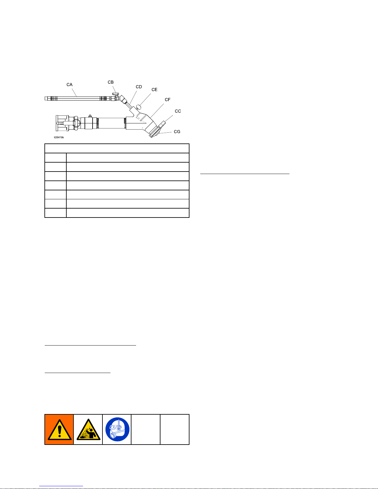
Key: Key:
Key:
CA
AirAssistAirLine
CBAirAssistShutoffBallValve
CC
RubberTipRetainer
CDAirNeedle(adjustableposition)
CEAirNeedleRetainingScrew
CF
FluidHousing
CGTip(Nozzle)
NOTE: NOTE:
NOTE:
SeethePoleSprayApplicatormanualfor
modelinformation.
General General
General
Adjustments Adjustments
Adjustments
Thespraypatterncanbeadjustedbychanging:
•Tip(CG)size
•Fluidand/orairow
•AirNeedle(CD)position
Thestandardapplicatoradjustmentistoadjusttheair
needle(CD)slightlybehindtheuidtip.Fullyopenthe
airballvalve(CB)fortheminimumairownecessaryfor
agoodpattern.NOTE: NOTE:
NOTE:
Installingtheneedle(CD)toofar
forwardcanreducetheoricesize,stoppingmaterialow.
Airbleedsfromtheapplicatornozzle
wheneverthe
applicatorairballvalve(CB)isopen.Closethevalveto
stoptheairifdesired.Otherwise,theairvalvecanstay
openduringpriming.
Adjustingthespraypattern
requirestestingtobalancethe
uidowandtheairtotheapplicator,andrequiresthe
correcttipsize.
Spraying Spraying
Spraying
Techniques Techniques
Techniques
1.Testthespraypatternoncardboard.Holdthe
applicator18–30in.(45–76cm)awayfrom
thesurface.Usethissprayingdistanceformost
applications.
2.Adjustuidowuntilmaterialowisadequate.
3.Adjusttheapplicatorairballvalve(CB)toachievea
uniformroundspraypattern.
4.Considerthesizeofaggregateinthematerialandthe
coarsenessofthespraypattern.Largernozzlesallow
heavierpatterns.
5.Overlapeachstroke50%.Acircularoverlapping
patternmaygivethebestresults.
Whensprayingsmallconnedareas
usetheairballvalve
(CB)andairneedle(CD)tomakeneadjustmentswithout
adjustingthepump.
Material Material
Material
Flow Flow
Flow
Adjustment Adjustment
Adjustment
Foralighterspraypattern,adjusttheairneedle(CD)
closertotheuidnozzleand/orreducetheuidow.For
aheavierspraypattern,adjusttheairneedle(CD)farther
backfromtheuidtipand/orincreasetheuidow.
NOTE: NOTE:
NOTE:
Withdrawingtheneedle(CD)toofarcanforceair
pressurebackintotheuidhose,whichcanslowmaterial
ow.
Air Air
Air
Flow Flow
Flow
Valve Valve
Valve
Adjustment Adjustment
Adjustment
Todecreaseairow,turntheairballvalve(CB)
clockwise.Toincreaseairow,turntheairballvalve(CB)
counterclockwise.
Checkthematerialandthinitasneededtomaintainthe
properconsistency.Thematerialmaythickenasitsitsand
couldslowdownapplicationoraffectthespraypattern.
Flushanddrytheapplicatorthoroughlyattheendofeach
use.Blowairthroughtheneedleaftertheapplicatoris
cleantoensurethatnomaterialisblockingairow.
Installing Installing
Installing
Nozzle Nozzle
Nozzle
Retaining Retaining
Retaining
Cap Cap
Cap
1.Placethenozzleretainingcap(CC)overthetoplip
oftheapplicatorhousing.
2.Turntherubberretainerbackandforthtomakesureit
isfullyseated.
3.Turntherubberretainerbackandforthtobesureit
isfullyseated.
NOTE: NOTE:
NOTE:
Therubbergasketinthecamandgrooveinlettting
andtherubbernozzleretainershouldbehand-cleanedand
driedaftereachuse.
3A3437F 19
Page 20
SprayAdjustments(HTXTMApplicator)
Spray Spray
Spray
Adjustments Adjustments
Adjustments
(HTX (HTX
(HTX
T TTM M
M
Applicator) Applicator)
Applicator)
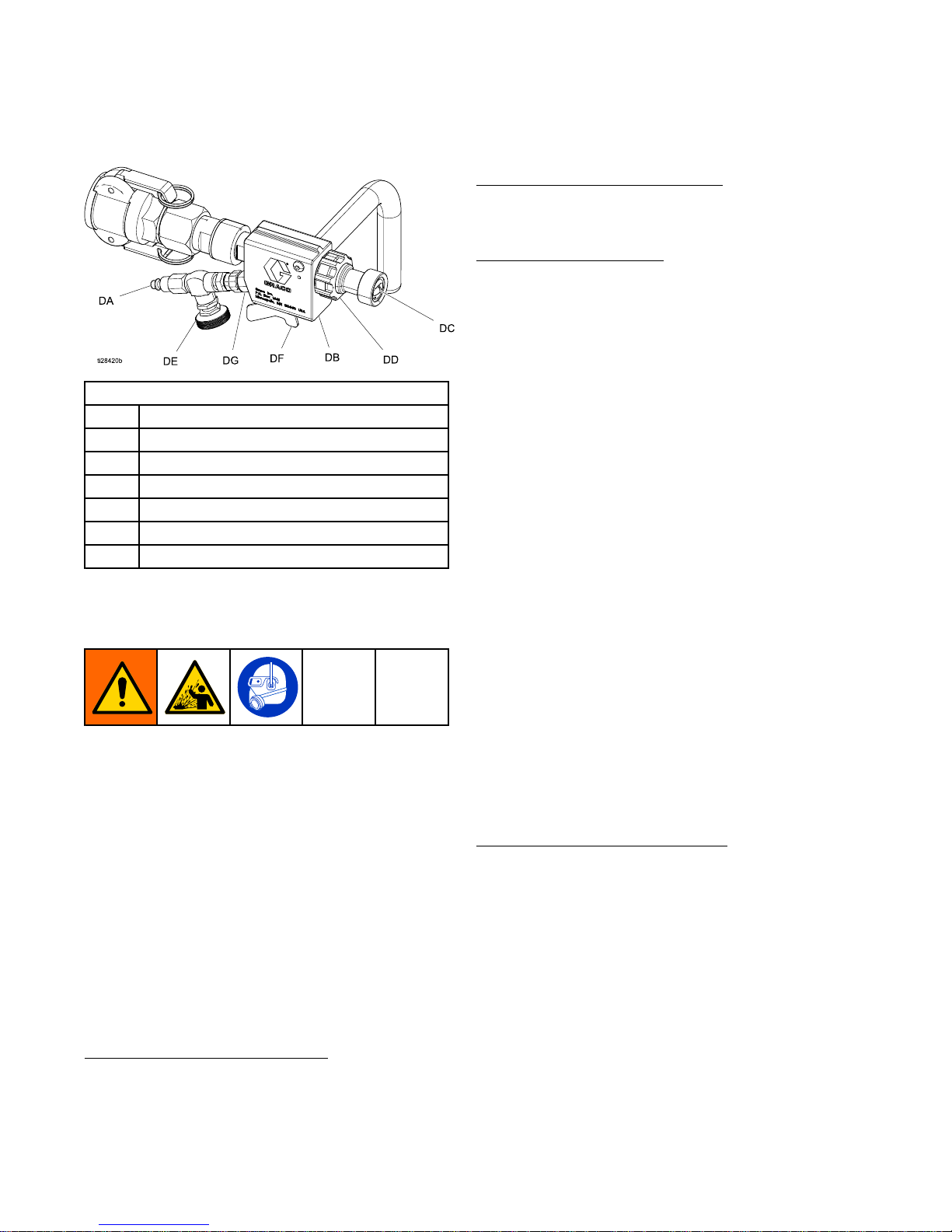
Key: Key:
Key:
DAAirAssistAirLine
DB
FluidandAirManifold
DCTip(Nozzle)
DDTipRetainer
DEAirAssistNeedleValve
DF
AirAssistShutOffBallValve
DGCheckValve
NOTE: NOTE:
NOTE:
SeetheHTXApplicatormanualformodel
information.
When When
When
Spraying Spraying
Spraying
1.Setmaterialow.Seeapplicatorinstruction
manualforadditionalinformation.
2.Spraytestpattern.
3.TurntheairknobONandadjust,and/orselect
anotherairnozzlefordesiredpattern.
NOTE: NOTE:
NOTE:
Aircontinuestoowwhenthehandleisinthe
OFFpositiontokeepmaterialoutofairpassages.
General General
General
Adjustments Adjustments
Adjustments
Thespraypatterncanbeadjustedbychanging:
•Tip(DC)size
•Fluidow
•Airow,useneedlevalve(DE)
Thestandardapplicatoradjustment
istofullyopen
theairassistvalve(DF)whileadjustingtheneedle
valve(DE)fortheminimumairownecessaryfor
agoodpattern.
Airbleedsfromtheapplicatornozzle
whenevertheair
assistvalve(DF)isopen.Closethevalvetostopthe
airowifdesired.Otherwise,theairvalvecanstay
openduringpriming.Airmustbeonpriortouidow.
Adjustingthespraypatternrequirestestingto
balancetheuidowandtheairtotheapplicator,
andrequiresthecorrecttipsize.
Air Air
Air
Flow Flow
Flow
Valve Valve
Valve
Adjustment Adjustment
Adjustment
Todecreaseairow,turnthevalveknob(DE)
clockwise.Toincreaseairow,turnthevalveknob
(DE)counterclockwise.
Checkmaterialandthinasneededtomaintainthe
properconsistency.Thematerialmaythickenasit
sitsandcouldslowdownapplicationoraffectthe
spraypattern.
Flushanddrytheapplicatorthoroughlyattheendof
eachuse.
Spray Spray
Spray
Techniques Techniques
Techniques
1.Testthespraypatternoncardboard.Holdthe
applicator6–18in.(15–46cm)fromthesurface.
Usethissprayingdistanceformostapplications.
2.Adjustuidowuntilmaterialowisadequate.
3.Adjusttheapplicatorairassistneedlevalveto
achieveauniformroundspraypattern.
4.Considerthesizeoftheaggregateinthematerial
andthecoarsenessofthespraypattern.Larger
nozzlesallowheavierpatterns.
5.Overlapeachstroke50%.Acircularoverlapping
patternmaygivethebestresults,andisobtained
bygraspingtheex-headandswingingthehead
aroundasthehoseexes.
Whensprayingsmallconnedareas
usethevalve
andknobtomakeneadjustmentswithoutadjusting
thepump.
Cleanup Cleanup
Cleanup
Thoroughlyushapplicatoraftereachworksession
beforeuidbeginstocureintheapplicator.Remove
thecheckvalveandcleanallresiduefromair
passages.Storeinadrylocation.Donotleavethe
applicatororanypartsinwaterorcleaningsolvents.
NOTE: NOTE:
NOTE:
Thecheckvalvewillbedamagedifanyobject
isinsertedintothevalve.
20 3A3437F
Page 21
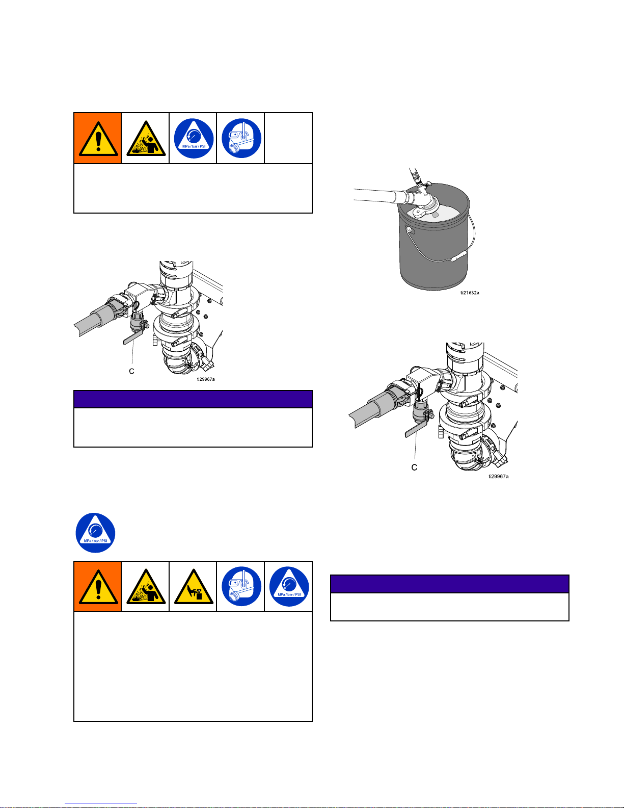
FluidDrain/PurgeValve
Fluid Fluid
Fluid
Drain/Purge Drain/Purge
Drain/Purge
Valve Valve
Valve
Toavoidinjuryfromsplashinguid,never
openacam-lockhoseorapplicatortting
whilethereispressureintheuidline.See
PressureReliefProcedure,page21.
Openthedrain/purgevalve(C)torelievepressureif
pumporhosepack-outoccurs,ortorelievepressure
insidethehose.Closevalvewhenspraying.
NOTICE NOTICE
NOTICE
Topreventmaterialhardeninginuiddrain/purge
valve,ushthevalveaftereverytimeitisused.
SeeFlush,page14.
Pressure Pressure
Pressure
Relief Relief
Relief
Procedure Procedure
Procedure
FollowthePressureReliefProcedure
wheneveryouseethissymbol.
Thisequipmentstayspressurizeduntilpressureis
manuallyrelieved.Tohelppreventseriousinjury
frompressurizeduid,suchassplashinguid,and
movingparts,followthePressureReliefProcedure
whenyoustopsprayingandbeforecleaning,
checking,orservicingtheequipment.
Toavoidinjuryfromsplashinguid,neveropena
cam-lockhoseorapplicatorttingwhilethereis
pressureintheuidline.
1.Turntheowadjustmentknob(H)
counterclockwiseuntilitstops.
2.Turnthemotorpowerswitch(S)off.
3.Removetheapplicatortipandthetipretainer.
4.Holdtheapplicatorrmlyagainstawaste
container.
ti2
1632a
5.Placeawastecontainerbeneaththeuid
drain/purgevalve(C).Slowlyopentheuid
drain/purgevalve(C)atthepumpoutlet.
6.Ifyoususpectthereisaclogwhichwillnot
allowpressuretobefullyrelieved,ushtheline
throughtheuiddrain/purgevalve(C)usinga
3/8polyurethanetubeandwaterhose.
7.Flushtheuiddrain/purgevalve(C).See
Flush,page14.Closetheuiddrain/purgevalve
(C).
NOTICE NOTICE
NOTICE
Topreventmaterialhardeninginuiddrain/purge
valve,ushthevalveaftereveryuse.
3A3437F
21
Page 22
HopperRemoval
Hopper Hopper
Hopper
Removal Removal
Removal
Tohelppreventinjuryfromsuction,neverplace
handsnearthepumpuidinletwhenpumpis
operatingorwhenhopperisremoved.
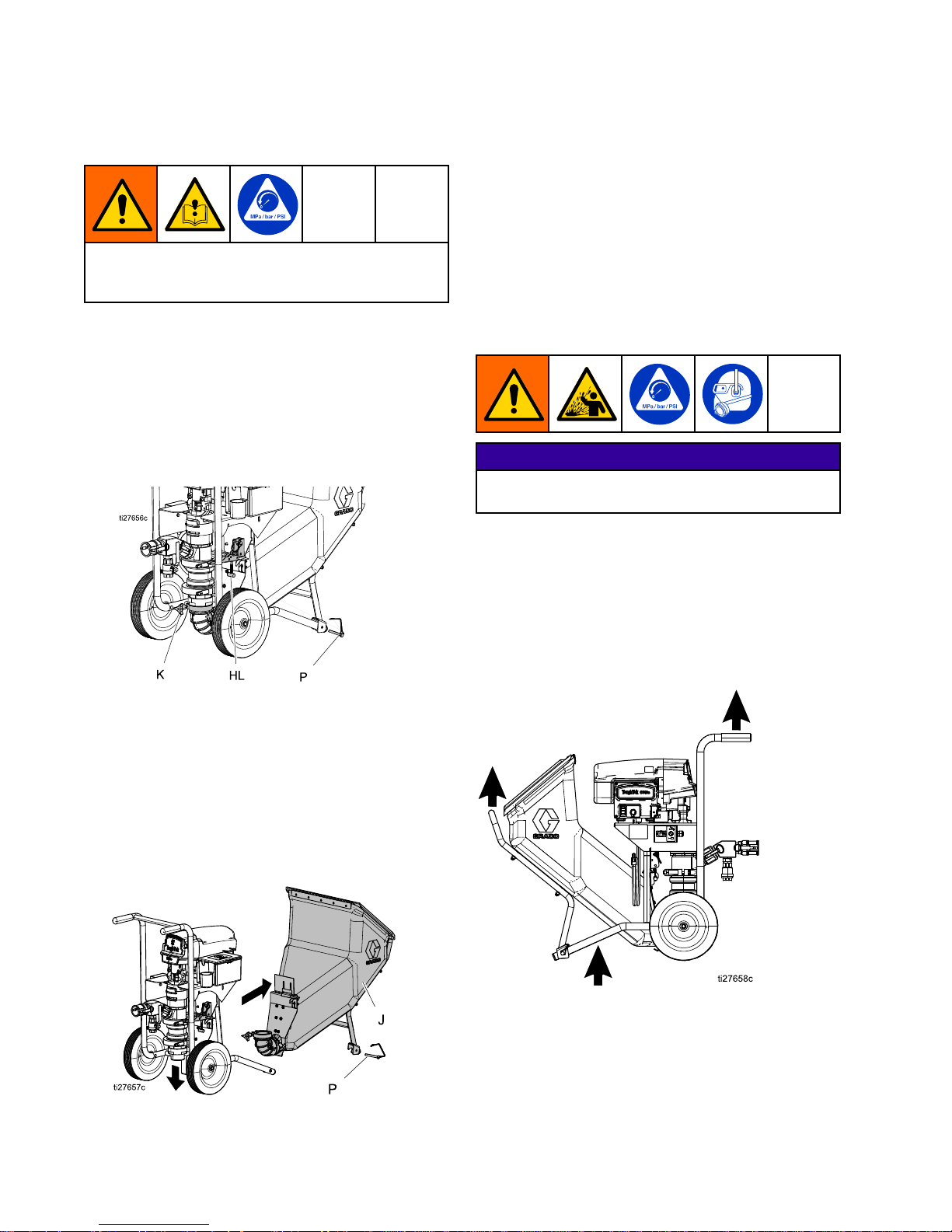
Thehopperassemblyallowseasydetachmentofthe
hopperfromthepump.Toremovethehopperfrom
thepump,performthefollowingsteps:
1.Relievepressure(see
PressureReliefProcedure,page21).
2.Unplugthepowercord.
3.Rotateknob(K)counterclockwisetoloosenthe
clampbetweenthehopperelbowandthelower.
4.Removethelockingpinandpulldownthehopper
latch(U)onthehopperplate.
NOTE: NOTE:
NOTE:
Ifneeded,pushdownonthehopper
elbowtocompletelydisengagefromthepump
lower.
5.Removethetwohopperpins(P)fromthefront
legsofthecart.
6.Liftuponthehandleandpullthehopper(J)away
fromthesprayer.
NOTE: NOTE:
NOTE:
Ifthehopperelbowneedstobethoroughly
cleaned,rotateknob(K)toloosentheclampbetween
theelbowandthehopper.Removeandcleanthe
elbow.
NOTE: NOTE:
NOTE:
Tore-installthehopper,followthesteps
aboveinreverseorder.
Shutdown Shutdown
Shutdown
NOTICE NOTICE
NOTICE
Topreventrust,neverleavewaterorwater-based
uidinpumpovernight.
Toshutdown,ushthesystem(seeFlush,page14).
Lifting Lifting
Lifting
Instructions Instructions
Instructions
Whenliftingtheunit,onlyliftatthepointsindicated
bythearrowsbelow.
22
3A3437F
Page 23
Maintenance
Maintenance Maintenance
Maintenance
Daily Daily
Daily
Maintenance Maintenance
Maintenance
1.Flushthesystem.SeeFlush,page14.
2.Cleanhopperwithascrubpad.Itis
recommendedthatyoucleantheoutsideofthe
sprayerusingaclothandwater.
3.Checkhoses,tubes,andcouplingsforwearor
damage.Tightenalluidconnectionsbefore
eachuse.
4.Checkandreplacecam-lockgasketsasneeded.
Preventative Preventative
Preventative
Maintenance Maintenance
Maintenance
Theoperatingconditionsofyourparticularsystem
determinehowoftenmaintenanceisrequired.
Establishapreventativemaintenancescheduleby
recordingwhenandwhatkindofmaintenanceis
needed,andthendeterminearegularschedulefor
checkingyoursystem.
DAILY: DAILY:
DAILY:
Checkhoseforwearanddamage,andleaks.
DAILY: DAILY:
DAILY:
Checkuiddrain/purgevalveforproper
operation.
DAILY: DAILY:
DAILY:
ChecklevelofThroatSealLiquid(TSL)in
displacementpumppackingnut/wetcup.Fillnut
1/2fullwithTSL.MaintainTSLleveltohelpprevent
materialbuilduponpistonrodandprematurewear
ofpackingsandpumpcorrosion.
DAILY: DAILY:
DAILY:
Checkthecamlockconnectionsfordamage
(dings,nicks,cracks)
DAILY: DAILY:
DAILY:
Checkthecamlockgasketfordamage.
DAILY DAILY
DAILY
(or (or
(or
when when
when
changing changing
changing
material): material):
material):
Breakdownthe
pumplowerandthoroughlycleanandinspectcheck
balls.
WEEKLY: WEEKLY:
WEEKLY:
Greaseswivelttingsontheapplicator.
WEEKLY WEEKLY
WEEKLY
(or (or
(or
when when
when
changing changing
changing
material): material):
material):
Breakdown
thepumplowerandthoroughlycleanandinspect
allwearcomponentsincludingcheckballs,piston,
o-ringsandseats.
Corrosion Corrosion
Corrosion
Protection Protection
Protection
NOTICE NOTICE
NOTICE
Topreventrust,neverleavewateror
water-baseduidinthepumpovernight.
NOTICE NOTICE
NOTICE
Materialleftonthethroatsealcandryoutand
damagetheseal.Alwaysstopthepumpat
thebottomofthestroketoavoiddamageto
thethroatseal.
Alwaysushthepumpbeforetheuiddriesonthe
displacementrod.
Water Water
Water
Exposure Exposure
Exposure
NOTICE NOTICE
NOTICE
Exposingthemotorand/orcontroltowater
cancausedamageandpossiblemotorfailure.
Donotstorethepumpoutside.Donotspray
waterdirectlyintothemotorfan.
3A3437F 23
Page 24
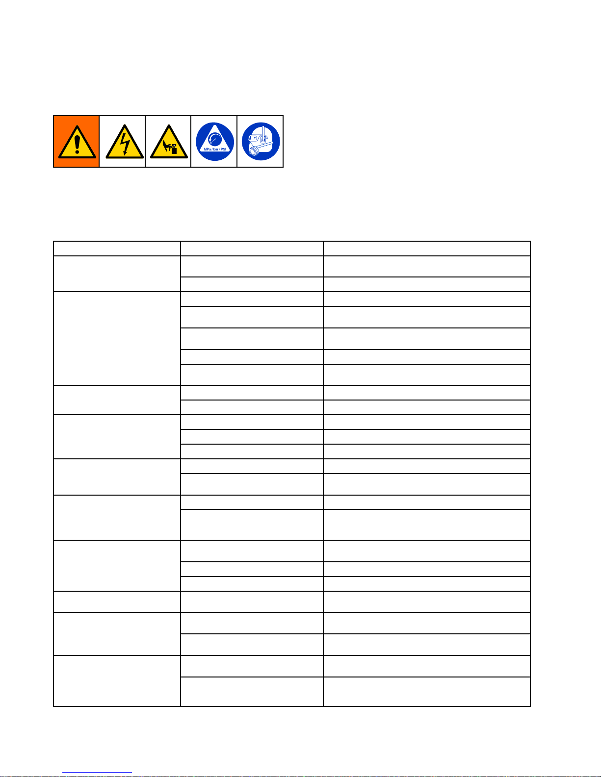
Troubleshooting
Troubleshooting Troubleshooting
Troubleshooting
1.PerformPressureReliefProcedure,page21.
2.Checkallpossibleproblems,causes,and
solutionslistedbelowbeforedisassembling
pump.
Fortroubleshootingandrepairquestions,please
contactyourdistributor.
Mechanical/Fluid Mechanical/Fluid
Mechanical/Fluid
Flow Flow
Flow
Problem Problem
Problem
Cause Cause
Cause
Solution Solution
Solution
Pistonballchecknotseating
properly
Servicethepistonballcheck.
Displacementpumpoperates,
butoutputislowonupstroke
PistonwornordamagedReplacethepiston.
PistonpackingswornordamagedReplacepiston.
Outletcheckvalvenotseating
properly
Cleanthecheckvalve.
Intakevalveballchecknotseating
properly
Servicetheintakevalveballcheck.
RubberelbowairleakTightenclampsontherubberelbow.
Displacementpumpoperates,
butoutputislowondown
strokeand/oronbothstrokes
Fluidhoseontheapplicatoris
obstructed
Cleantheuidhoseontheapplicator.
LoosewetcupTightenthewetcupenoughtostopleakage. Materialleaksandrunsover
thesideofthewetcup
ThroatsealwornordamagedReplacethethroatseal.
Applicatortip/gunisdirtyorclogged
Cleanorreplacetip/gun.
Clampsonhopperelbowareloose
Tightenclampsonthehopperelbow.
Fluiddeliveryislow
Largepressuredropinuidhose
Reducelengthorincreasediameter.
PowerswitchisnotONTurnthepowerswitchON.
Electricmotordoesnotoperate
Trippedcircuitbreaker
Checkcircuitbreakeratpowersource.Resetmotor
switch.
Fluidhoseorapplicatorobstructed
Cleanthehoseorapplication.
Sprayerdoesnotoperate
Drieduidondisplacementrodor
inletball
Cleanrod.Alwaysstoppumpatbottomofstroke;
keepwetcuplledwithTSL.Besuretheinletball
movesfreely.
Materialsupplyexhausted,clogged
suction
Rellthehopperandtheprimepump.
OpenorwornpistonballClearpistonvalve;servicethepistonballcheck.
Erraticacceleratedspeed
OpenorwornintakevalveClearorserviceintakevalve.
Cyclesorfailstoholdpressure
atstall
Worncheckballs,seats,orpiston
packing
Servicethepumplower.
Inadequateatomizingairpressure
Adjustairneedlevalveonapplicator(seeapplicator
manual).
Poornishorirregularspray
pattern
Dirty,worn,ordamagedspray
applicator
Servicesprayapplicator(seeapplicatormanual).
Pumpispackedoutwithdryor
curedmaterial
DisassembleandCleanthepump.
Motorpoweredbutnothing
comesoutofhose
Hoseispackedoutwithdryor
curedmaterial
Trytoushthehoseusingwaterhoseand/or
polyurethanetube.
24
3A3437F
Page 25
Troubleshooting
Problem Problem
Problem
Cause Cause
Cause
Solution Solution
Solution
Thinandmixmaterialthoroughlytoalower
viscosity.
Useapumpsystempriminguid(slime).Wetout
thesystem.
Usealargerdiameterhose.
Materialistoothicktopush
throughthehosewithout
packingout
Hoseistoorestrictive
Thoroughlymixinapump-aidorperformance
admixturetothematerial.
Electrical Electrical
Electrical
Problem Problem
Problem
Cause Cause
Cause
Solution Solution
Solution
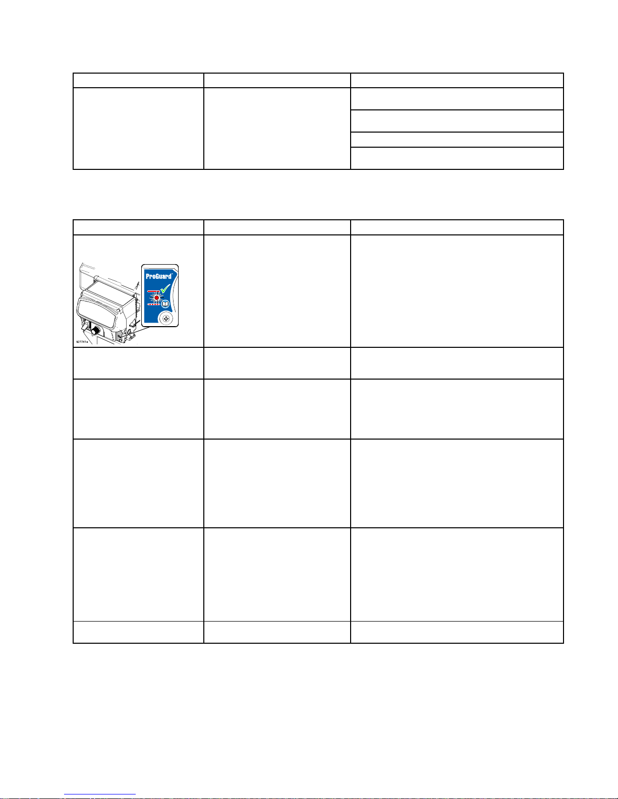
Controlboardstatuslightblinks
4timesrepeatedly
Thecontrolboardisdetecting
multiplevoltagesurges
Checkvoltagesupplytothesprayer:
1.Turnthemotorpowerswitch(S)toOFFand
unplugthesprayer.
2.Locateagoodvoltagesupplytoprevent
damagetoelectronics.
Controlboardstatuslightblinks
5timesrepeatedly
Checkforlineobstructionorpack
out.Motorispoweredbutnotable
toturn.
Openthereliefvalvetorelievepressure.Remove
theobstructionandcyclepoweroffandon.Ifthe
problemcontinues,contactyourlocaldistributor.
Controlboardstatuslightblinks
6timesrepeatedly
Themotorisoverheating
Allowthesprayertocool.Ifthesprayerrunswhen
cool,correctthecauseofoverheating.Keepthe
sprayerinacoolerlocationwithgoodventilation.
Makesurethemotorairintakeisnotblocked.If
thesprayerstilldoesnotrun,contactyourlocal
distributor.
Controlboardstatuslightblinks
8timesrepeatedly
Incomingvoltageistoolowfor
sprayeroperation
Checkvoltagesupplytothesprayer:
1.Turnthemotorpowerswitch(S)toOFFand
unplugthesprayer.
2.Removeotherequipmentthatusesthesame
circuit.
3.Locateagoodvoltagesupplytoavoiddamage
toelectronics.
Controlboardstatuslightblinks
10timesrepeatedly
Thecontrolboardisoverheating1.Makesurethemotorairintakeisnotblocked.
2.Makesurethefanhasnotfailed.
3.Makesurethecontrolboardisproperly
connectedtothebackplateandthatconductive
thermalpasteisusedonpowercomponents.
4.Replacethecontrolboard.
5.Replacethemotor.
Controlboardstatuslightblinks
12timesrepeatedly
Excessivecurrentprotectionis
enabled
Cyclethepoweronandoff.
3A3437F 25
Page 26

Troubleshooting
Problem Problem
Problem
Cause Cause
Cause
Solution Solution
Solution
Controlboardstatuslightblinks
15timesrepeatedly
Connectionsabovethemotormay
arelooseordamaged
1.Turnthemotorpowerswitch(S)toOFFand
unplugthesprayer.
2.Removethemotorshroud.
3.Disconnectthemotorcontrolandinspectfor
damageattheconnectors.
4.Reconnectthemotorcontrol.
5.Turnthemotorpowerswitch(S)toON.Ifthe
blinkingcodecontinues,replacethemotor.
Controlboardstatuslightblinks
16timesrepeatedly
Checktheconnections.Check
forwaterinsensor.Controlisnot
receivingmotorpositionsensor
signal.
1.TurnpowerOFF.
2.Removethemotorshroud.
3.Disconnectthemotorcontrolandinspectfor
damageattheconnectors.
4.Inspectthesensorforwater.Ifthesensoris
wet,letitdryfor24hours.
5.Re-installthesensor,motorcontrolconnections,
andshroud.
6.TurnpowerON.Iftheproblemcontinues,
replacethemotor.
Controlboardstatuslightblinks
17timesrepeatedly
Thesprayerispluggedintothe
wrongvoltage
1.Setthemotorpowerswitch(S)toOFFand
unplugthesprayer.
2.Locateagoodvoltagesupplytoavoiddamage
toelectronics.
26 3A3437F
Page 27
Repair
Repair Repair
Repair
Replace Replace
Replace
Pump Pump
Pump
Lower Lower
Lower
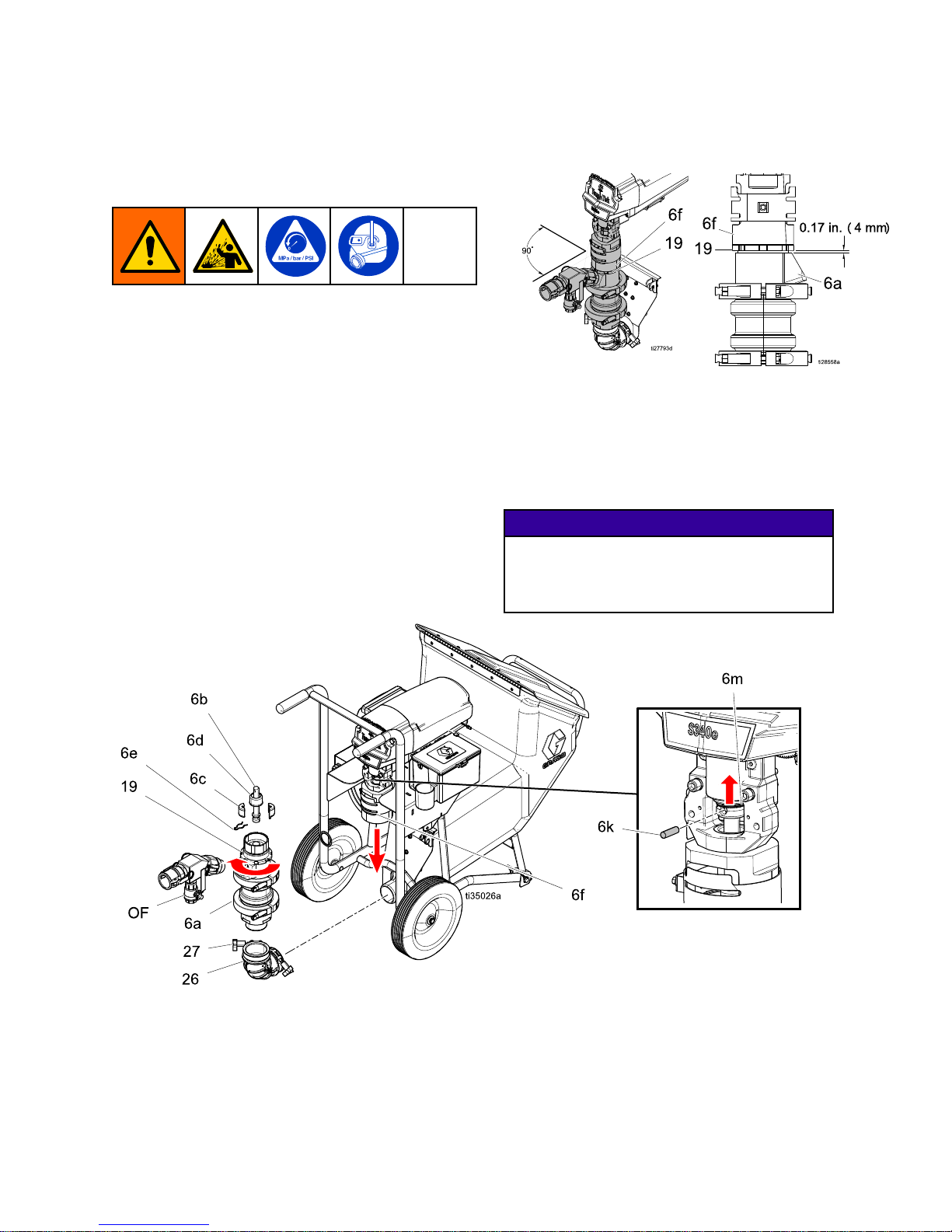
Performtheprocedurebelowtoreplacetheentire
pumplowerwithanewordifferentpumplower.
1.PerformthePressureReliefProcedure,page21.
2.Disconnectthehopper,materialhose,and
power.
3.Removeoutletttings(OF)fromthepumplower
(6a)outlet.
4.Liftretainingspring(6m)andremovepin(6k).
5.Loosenjamnut(19)andunthreadthepump
lower(6a).
6.Disconnectthepistonextensionrod(6b)by
removingclip(6e)anddisassemblingthecoupler
cover(6d)andassemblycoupling(6c).The
pumplower(6a)shouldnowbeseparatedfrom
allotherparts.Replacethepumplowerand
reinstallontheunit.Ifpumpcomponentsneed
replacing,seeReplacePumpComponents
NOTE: NOTE:
NOTE:
Whenreinstallingthepumplower,thejam
nut(19)shouldbethreadedonthepumploweruntil
itbottomsout.Thepumplowershouldbethreaded
completelyintothemotoradapter(6f)andbacked
offtothecorrectorientationpositionshownabove.
Onceinposition,unthreadthepumptwoadditional
turnsandsecurethejamnut.
NOTICE NOTICE
NOTICE
Failuretoassemblethepumplowertothe
correctdepthandorientationcancause
damagetothepump.Toavoiddamagetothe
pump,followtheNote Note
Note
above.
3A3437F
27
Page 28
Repair
Replace Replace
Replace
Pump Pump
Pump
Components Components
Components
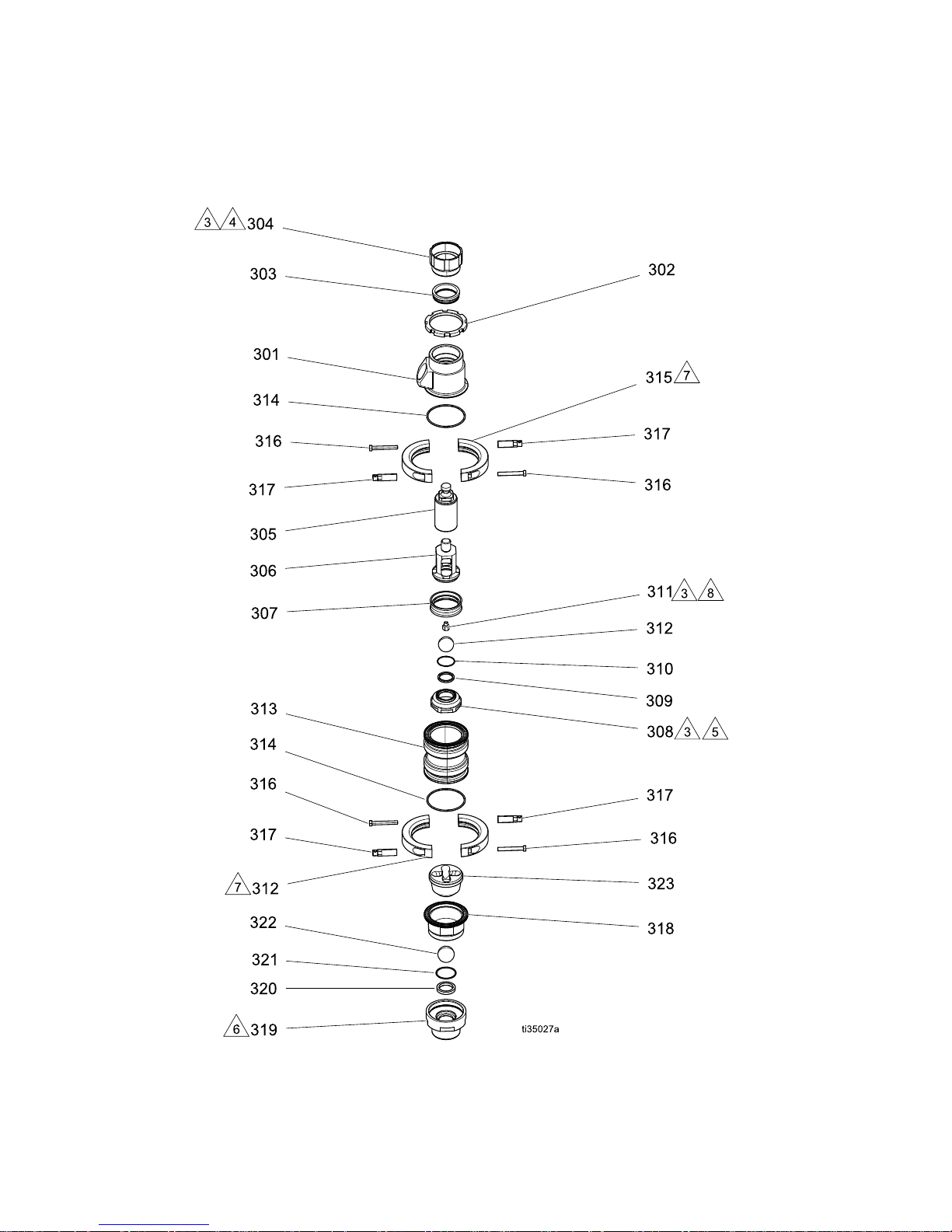
Remove Remove
Remove
the the
the
pump pump
pump
lower lower
lower
(6a (6a
(6a
– ––17G864) 17G864)
17G864)
before before
before
replacing replacing
replacing
any any
any
pump pump
pump
components. components.
components.
For For
For
a aalist list
list
of ofofavailable available
available
pump pump
pump
lower lower
lower
kits, kits,
kits,
see see
see
the the
the
list list
list
on on
on
the the
the
following following
following
page. page.
page.
28 3A3437F
Page 29

Repair
Pump Pump
Pump
Components Components
Components
Parts Parts
Parts
List List
List
Ref. Ref.
Ref.
Part Part
Part
Description Description
Description
Qty. Qty.
Qty.
301 301
301
17G220 17G220
17G220
HOUSING, HOUSING,
HOUSING,
outlet outlet
outlet
1 1
1
302 302
302
17G859 17G859
17G859
NUT, NUT,
NUT,
jam, jam,
jam,
black black
black
1 1
1
303 303
303
17G865 17G865
17G865
KIT, KIT,
KIT,
bearing, bearing,
bearing,
seal seal
seal
throat, throat,
throat,
3–pack 3–pack
3–pack
1 1
1
304 304
304
17G321 17G321
17G321
NUT, NUT,
NUT,
packing, packing,
packing,
340e 340e
340e
1 1
1
305 305
305
17G331 17G331
17G331
ROD, ROD,
ROD,
short, short,
short,
displacement displacement
displacement
1 1
1
306 306
306
17G795 17G795
17G795
GUIDE, GUIDE,
GUIDE,
ball, ball,
ball,
piston piston
piston
1 1
1
307 307
307
16W491 16W491
16W491
PACKING, PACKING,
PACKING,
cup, cup,
cup,
3–pack 3–pack
3–pack
1 1
1
308 308
308
17G794 17G794
17G794
VALVE, VALVE,
VALVE,
piston piston
piston
1 1
1
309 309
309
† †
†
SEAT, SEAT,
SEAT,
carbide, carbide,
carbide,
valve, valve,
valve,
piston piston
piston
1 1
1
310 310
310
† †
†
PACKING, PACKING,
PACKING,
o oo- --ring ring
ring
1 1
1
311 311
311
17G817 17G817
17G817
STOP, STOP,
STOP,
ball, ball,
ball,
piston piston
piston
1 1
1
312 312
312
17G798† 17G798†
17G798†
BALL, BALL,
BALL,
neoprene, neoprene,
neoprene,
cs cs
cs
core, core,
core,
1.625 1.625
1.625
1 1
1
313 313
313
17G330 17G330
17G330
CYLINDER, CYLINDER,
CYLINDER,
short short
short
1 1
1
314 314
314
† †
†
PACKING, PACKING,
PACKING,
o oo- --ring ring
ring
2 2
2
315 315
315
† †
†
CLAMP, CLAMP,
CLAMP,
4 44in., in.,
in.,
1000 1000
1000
psi psi
psi
2 2
2
316 316
316
† †
†
SCREW, SCREW,
SCREW,
cap, cap,
cap,
hex hex
hex
hd hd
hd
4 4
4
317 317
317
† †
†
NUT, NUT,
NUT,
extension, extension,
extension,
3/8–16 3/8–16
3/8–16
4 4
4
Ref. Ref.
Ref.
Part Part
Part
Description Description
Description
Qty. Qty.
Qty.
318 318
318
17G226 17G226
17G226
HOUSING, HOUSING,
HOUSING,
inlet, inlet,
inlet,
ball ball
ball
guide guide
guide
1 1
1
319 319
319
17G221 17G221
17G221
HOUSING, HOUSING,
HOUSING,
inlet inlet
inlet
1 1
1
320 320
320
† †
†
SEA, SEA,
SEA,
carbide, carbide,
carbide,
valve, valve,
valve,
inlet inlet
inlet
1 1
1
321 321
321
† †
†
O OO- --RING, RING,
RING,
50 50
50
mm mm
mm
x xx2.5 2.5
2.5
mm mm
mm
1 1
1
322 322
322
15H833† 15H833†
15H833†
BALL, BALL,
BALL,
neo/sst neo/sst
neo/sst
core, core,
core,
1.75 1.75
1.75
in. in.
in.
1 1
1
323 323
323
17G793 17G793
17G793
GUIDE, GUIDE,
GUIDE,
ball, ball,
ball,
inlet inlet
inlet
1 1
1
†
See See
See
List List
List
of ofofKits Kits
Kits
table table
table
for for
for
more more
more
information. information.
information.
1
Apply Apply
Apply
grease grease
grease
lubricant lubricant
lubricant
to totothreads, threads,
threads,
o oo- --rings rings
rings
and and
and
seals. seals.
seals.
2
Apply Apply
Apply
serviceable serviceable
serviceable
thread thread
thread
locker locker
locker
to totothreads. threads.
threads.
3
Apply Apply
Apply
anti anti
anti
- --seize seize
seize
to totothreads. threads.
threads.
4
Torque Torque
Torque
to toto30 30
30
+/ +/+/- --5 55ft ftft- --lb lblb(40 (40
(40
+/ +/+/- --6.7 6.7
6.7
N●m). N●m).
N●m).
5
Torque Torque
Torque
to toto100 100
100
+/ +/+/- --5 55ft ftft- --lb lblb(135 (135
(135
+/ +/+/- --13.5 13.5
13.5
N●m). N●m).
N●m).
6
Torque Torque
Torque
to toto200 200
200
+/ +/+/- --5 55ft ftft- --lb lblb(271 (271
(271
+/ +/+/- --13.5 13.5
13.5
N●m). N●m).
N●m).
7
Orient Orient
Orient
clamps clamps
clamps
approximately approximately
approximately
as as
as
shown. shown.
shown.
8
Torque Torque
Torque
to toto10 10
10
+/ +/+/- --2 22ft ftft- --lb lblb(13 (13
(13
+/ +/+/- --2.7 2.7
2.7
N●m). N●m).
N●m).
List List
List
of of
of
Kits Kits
Kits
Kit Kit
Kit
Description Description
Description
Kit Kit
Kit
Contents Contents
Contents
25A233 25A233
25A233
Pump Pump
Pump
rebuild rebuild
rebuild
kit kit
kit
303 303
303
(1), (1),
(1),
307 307
307
(1), (1),
(1),
310 310
310
(1), (1),
(1),
312 312
312
(1), (1),
(1),
314 314
314
(2), (2),
(2),
321 321
321
(1), (1),
(1),
322 322
322
(1) (1)
(1)
17G456 17G456
17G456
Pump Pump
Pump
lower lower
lower
clamp clamp
clamp
kit kit
kit
315 315
315
(1), (1),
(1),
316 316
316
(2), (2),
(2),
317 317
317
(2) (2)
(2)
17G862 17G862
17G862
Piston Piston
Piston
seat seat
seat
and and
and
o oo- --ring ring
ring
309 309
309
(1), (1),
(1),
310 310
310
(1) (1)
(1)
17G863 17G863
17G863
Inlet Inlet
Inlet
seat seat
seat
and and
and
o oo- --ring ring
ring
320 320
320
(1), (1),
(1),
321 321
321
(1) (1)
(1)
25A467 25A467
25A467
Check Check
Check
ball ball
ball
repair repair
repair
kit kit
kit
312 312
312
(1), (1),
(1),
322 322
322
(1) (1)
(1)
16W490 16W490
16W490
Cylinder Cylinder
Cylinder
o oo- --ring ring
ring
kit kit
kit
314 314
314
(10) (10)
(10)
3A3437F 29
Page 30
Parts
Parts Parts
Parts
S340e S340e
S340e
Systems Systems
Systems
30 3A3437F
Page 31

Parts
Ref. Ref.
Ref.
Part Part
Part
Description Description
Description
Qty. Qty.
Qty.
2 2
2
17J707 17J707
17J707
HOPPER, HOPPER,
HOPPER,
340e, 340e,
340e,
with with
with
cover cover
cover
1 1
1
3 3
3
17J709 17J709
17J709
BRACKET, BRACKET,
BRACKET,
340e, 340e,
340e,
painted, painted,
painted,
hopper hopper
hopper
1 1
1
7 7
7
17J812 17J812
17J812
BRACKET, BRACKET,
BRACKET,
stop, stop,
stop,
adjustable, adjustable,
adjustable,
340e 340e
340e
1 1
1
9 9
9
17J710 17J710
17J710
LATCH, LATCH,
LATCH,
adjustable adjustable
adjustable
1 1
1
20 20
20
† †
†
BRACKET, BRACKET,
BRACKET,
stop, stop,
stop,
hopper hopper
hopper
1 1
1
21 21
21
† †
†
GASKET, GASKET,
GASKET,
hopper hopper
hopper
mount, mount,
mount,
340e 340e
340e
1 1
1
22 22
22
† †
†
PLATE, PLATE,
PLATE,
mount, mount,
mount,
threaded threaded
threaded
stud, stud,
stud,
340e 340e
340e
1 1
1
23 23
23
17G368 17G368
17G368
PIN, PIN,
PIN,
3/8 3/8
3/8
in. in.
in.
2 2
2
26 26
26
17H193 17H193
17H193
BOOT, BOOT,
BOOT,
elbow, elbow,
elbow,
rubber, rubber,
rubber,
3 3
3
in. in.
in.
ID ID
ID
1 1
1
27 27
27
17H196 17H196
17H196
CLAMP, CLAMP,
CLAMP,
hose, hose,
hose,
t tt- --belt belt
belt
2 2
2
28 28
28
– ––– ––– ––– ––– –
–
SCREW, SCREW,
SCREW,
pan pan
pan
head, head,
head,
machine, machine,
machine,
3/8–16 3/8–16
3/8–16
x xx2 22in. in.
in.
4 4
4
29 29
29
100731 100731
100731
WASHER WASHER
WASHER
8 8
8
Ref. Ref.
Ref.
Part Part
Part
Description Description
Description
Qty. Qty.
Qty.
30 30
30
101566 101566
101566
NUT, NUT,
NUT,
lock lock
lock
4 4
4
34 34
34
– ––– ––– ––– ––– –
–
SCREW, SCREW,
SCREW,
cap, cap,
cap,
hex hex
hex
hd hd
hd
6 6
6
39 39
39
125112 125112
125112
SCREW, SCREW,
SCREW,
cap, cap,
cap,
btn btn
btn
hd, hd,
hd,
5/16 5/16
5/16
in. in.
in.
4 4
4
40 40
40
† †
†
NUT, NUT,
NUT,
hex, hex,
hex,
ange ange
ange
head head
head
6 6
6
41 41
41
100527 100527
100527
WASHER, WASHER,
WASHER,
plain plain
plain
7 7
7
42 42
42
111040 111040
111040
NUT, NUT,
NUT,
lock, lock,
lock,
insert, insert,
insert,
nylock, nylock,
nylock,
5/16 5/16
5/16
7 7
7
44 44
44
17H025 17H025
17H025
PIN, PIN,
PIN,
1/4 1/4
1/4
in. in.
in.
x xx1–3/8 1–3/8
1–3/8
in. in.
in.
1 1
1
61 61
61
195551‡ 195551‡
195551‡
RETAINER, RETAINER,
RETAINER,
plug, plug,
plug,
adapter adapter
adapter
1 1
1
62 62
62
242005‡ 242005‡
242005‡
CORD CORD
CORD
SET, SET,
SET,
adapter, adapter,
adapter,
Australia Australia
Australia
1 1
1
63 63
63
242001‡ 242001‡
242001‡
CORD CORD
CORD
SET, SET,
SET,
adapter, adapter,
adapter,
Europe Europe
Europe
1 1
1
†
Included Included
Included
in ininStop Stop
Stop
Brackets Brackets
Brackets
Kit Kit
Kit
17J708. 17J708.
17J708.
‡
Only Only
Only
included included
included
in ininmodels models
models
25A304 25A304
25A304
and and
and
25A306. 25A306.
25A306.
3A3437F 31
Page 32
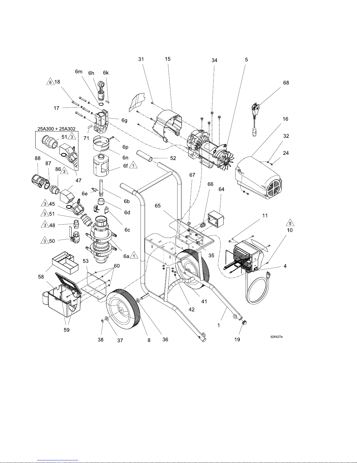
Parts
S340e S340e
S340e
Systems Systems
Systems
(continued) (continued)
(continued)
32 3A3437F
Page 33

Parts
Ref. Ref.
Ref.
Part Part
Part
Description Description
Description
Qty. Qty.
Qty.
1 1
1
– ––– ––– ––– ––– –
–
CART, CART,
CART,
340e, 340e,
340e,
painted painted
painted
1 1
1
4 4
4
†
MODULE, MODULE,
MODULE,
340e, 340e,
340e,
motor motor
motor
control, control,
control,
120V 120V
120V
1 1
1
†
MODULE, MODULE,
MODULE,
340e, 340e,
340e,
motor motor
motor
control, control,
control,
120V, 120V,
120V,
UK UK
UK
1 1
1
†
MODULE, MODULE,
MODULE,
340e, 340e,
340e,
motor motor
motor
control, control,
control,
230V 230V
230V
1 1
1
5 5
5
17J711 17J711
17J711
MOTOR, MOTOR,
MOTOR,
340e, 340e,
340e,
pump pump
pump
1 1
1
6a 6a
6a
17G864 17G864
17G864
PUMP, PUMP,
PUMP,
lower, lower,
lower,
S340e S340e
S340e
1 1
1
6b 6b
6b
17G283 17G283
17G283
ROD, ROD,
ROD,
extension, extension,
extension,
piston, piston,
piston,
340e 340e
340e
1 1
1
6c 6c
6c
244819 244819
244819
COUPLING, COUPLING,
COUPLING,
assembly, assembly,
assembly,
145–290 145–290
145–290
Xtreme Xtreme
Xtreme
1 1
1
6d 6d
6d
197340 197340
197340
COVER, COVER,
COVER,
coupler coupler
coupler
1 1
1
6e 6e
6e
116407 116407
116407
CLIP, CLIP,
CLIP,
hairpin hairpin
hairpin
1 1
1
6f 6f
6f
17G279 17G279
17G279
ADAPTER, ADAPTER,
ADAPTER,
pump pump
pump
to totomotor, motor,
motor,
340e 340e
340e
1 1
1
6g 6g
6g
– ––– ––– ––– ––– –
–
HOUSING, HOUSING,
HOUSING,
bearing bearing
bearing
1 1
1
6h 6h
6h
287395 287395
287395
ROD, ROD,
ROD,
connecting connecting
connecting
1 1
1
6k 6k
6k
183210 183210
183210
PIN, PIN,
PIN,
str, str,
str,
hdls hdls
hdls
1 1
1
6m 6m
6m
119778 119778
119778
SPRING, SPRING,
SPRING,
retaining retaining
retaining
1 1
1
6n 6n
6n
†
GUARD, GUARD,
GUARD,
nger, nger,
nger,
weldment, weldment,
weldment,
340e 340e
340e
1 1
1
6p 6p
6p
†
BOLT, BOLT,
BOLT,
special, special,
special,
5/16–24 5/16–24
5/16–24
1 1
1
8 8
8
17J706 17J706
17J706
WHEEL, WHEEL,
WHEEL,
semi semi
semi
pneumatic, pneumatic,
pneumatic,
offset offset
offset
2 2
2
10 10
10
16V095 16V095
16V095
SCREW, SCREW,
SCREW,
mach, mach,
mach,
pnh, pnh,
pnh,
torx, torx,
torx,
self self
self
tapping tapping
tapping
4 4
4
11* 11*
11*
17H175 17H175
17H175
PLUG, PLUG,
PLUG,
round round
round
1 1
1
11** 11**
11**
– ––– ––– ––– ––– –
–
GROMMET, GROMMET,
GROMMET,
3/16 3/16
3/16
in. in.
in.
ID IDIDx xx9/16 9/16
9/16
in. in.
in.
OD OD
OD
1 1
1
12 12
12
– ––– ––– ––– ––– –
–
WIRE, WIRE,
WIRE,
jumper, jumper,
jumper,
remote remote
remote
1 1
1
15 15
15
†
COVER, COVER,
COVER,
front, front,
front,
plastic, plastic,
plastic,
painted painted
painted
1 1
1
16 16
16
†
SHIELD, SHIELD,
SHIELD,
motor, motor,
motor,
painted painted
painted
1 1
1
17 17
17
106115 106115
106115
WASHER, WASHER,
WASHER,
lock lock
lock
(hi (hi
(hi
collar) collar)
collar)
4 4
4
18 18
18
114666 114666
114666
SCREW, SCREW,
SCREW,
cap, cap,
cap,
socket socket
socket
head head
head
4 4
4
19 19
19
– ––– ––– ––– ––– –
–
PLUG, PLUG,
PLUG,
tube tube
tube
2 2
2
24 24
24
119250 119250
119250
SCREW, SCREW,
SCREW,
shoulder shoulder
shoulder
2 2
2
31 31
31
118444 118444
118444
SCREW, SCREW,
SCREW,
mach, mach,
mach,
slot, slot,
slot,
hex hex
hex
wash wash
wash
hd hd
hd
4 4
4
32 32
32
276980 276980
276980
GROMMET, GROMMET,
GROMMET,
cover cover
cover
2 2
2
34 34
34
– ––– ––– ––– ––– –
–
SCREW, SCREW,
SCREW,
cap, cap,
cap,
hex hex
hex
hd hd
hd
6 6
6
Ref. Ref.
Ref.
Part Part
Part
Description Description
Description
Qty. Qty.
Qty.
35 35
35
117791 117791
117791
SCREW, SCREW,
SCREW,
cap, cap,
cap,
tri, tri,
tri,
lobe lobe
lobe
2 2
2
36 36
36
191824 191824
191824
WASHER, WASHER,
WASHER,
space space
space
2 2
2
37 37
37
111841 111841
111841
WASHER, WASHER,
WASHER,
plain, plain,
plain,
5/8 5/8
5/8
2 2
2
38 38
38
101242 101242
101242
RING, RING,
RING,
retaining, retaining,
retaining,
ext. ext.
ext.
2 2
2
41 41
41
100527 100527
100527
WASHER, WASHER,
WASHER,
plain plain
plain
7 7
7
42 42
42
111040 111040
111040
NUT, NUT,
NUT,
lock, lock,
lock,
insert, insert,
insert,
nylock, nylock,
nylock,
5/16 5/16
5/16
in. in.
in.
7 7
7
45 45
45
128758 128758
128758
FITTING, FITTING,
FITTING,
1.5 1.5
1.5
cmlk cmlk
cmlk
f ffx xx1.50 1.50
1.50
npt npt
npt
m m
m
1 1
1
47 47
47
17G408 17G408
17G408
MANIFOLD, MANIFOLD,
MANIFOLD,
outlet, outlet,
outlet,
pump pump
pump
1 1
1
48 48
48
17G388 17G388
17G388
FITTING, FITTING,
FITTING,
hose, hose,
hose,
1–11 1–11
1–11
1/2 1/2
1/2
npt npt
npt
1 1
1
50 50
50
127232 127232
127232
VALVE, VALVE,
VALVE,
ball, ball,
ball,
1000 1000
1000
psi, psi,
psi,
1 11in. in.
in.
1 1
1
51 51
51
128473 128473
128473
FITTING, FITTING,
FITTING,
1.5 1.5
1.5
in. in.
in.
camlock camlock
camlock
x xx1.5 1.5
1.5
in. in.
in.
nptm nptm
nptm
2 2
2
52 52
52
– ––– ––– ––– ––– –
–
GRIP, GRIP,
GRIP,
vinyl, vinyl,
vinyl,
gray, gray,
gray,
1.25 1.25
1.25
in. in.
in.
2 2
2
53 53
53
– ––– ––– ––– ––– –
–
BRACKET, BRACKET,
BRACKET,
F340e, F340e,
F340e,
mounting mounting
mounting
1 1
1
58 58
58
†
TOOL TOOL
TOOL
BOX BOX
BOX
1 1
1
59 59
59
†
SCREW, SCREW,
SCREW,
mach, mach,
mach,
pnh pnh
pnh
4 4
4
60 60
60
†NUT, NUT,
NUT,
keps, keps,
keps,
hex hex
hex
hd hd
hd
4 4
4
64 64
64
17G554 17G554
17G554
KIT, KIT,
KIT,
remote remote
remote
switch switch
switch
(includes (includes
(includes
68) 68)
68)
1 1
1
65 65
65
113161 113161
113161
SCREW, SCREW,
SCREW,
ange, ange,
ange,
hex hex
hex
hd hd
hd
1 1
1
66 66
66
114421 114421
114421
BUSHING, BUSHING,
BUSHING,
strain strain
strain
relief relief
relief
1 1
1
67 67
67
128596 128596
128596
GROMMET, GROMMET,
GROMMET,
5/16 5/16
5/16
in. in.
in.
ID IDIDx xx1 11in. in.
in.
OD OD
OD
1 1
1
68 68
68
17W604 17W604
17W604
MODULE, MODULE,
MODULE,
remote, remote,
remote,
ON/OFF ON/OFF
ON/OFF
1 1
1
86 86
86
– ––– ––– ––– ––– –
–
ADAPTER, ADAPTER,
ADAPTER,
1.5 1.5
1.5
m mmnpt npt
npt
x xx1.5 1.5
1.5
m mmbspp bspp
bspp
1 1
1
87 87
87
17N566 17N566
17N566
SEAL, SEAL,
SEAL,
1.5 1.5
1.5
in. in.
in.
bspp bspp
bspp
1 1
1
88 88
88
17N891 17N891
17N891
COUPLING, COUPLING,
COUPLING,
mortar, mortar,
mortar,
female, female,
female,
35 3535mm mm
mm
x xx1.5 1.5
1.5
f ffbspp bspp
bspp
1 1
1
* *
*
Only Only
Only
included included
included
in ininmodels models
models
25A300, 25A300,
25A300,
25C610, 25C610,
25C610,
and and
and
25A304. 25A304.
25A304.
** **
**
Only Only
Only
included included
included
in inin25A302, 25A302,
25A302,
25A306, 25A306,
25A306,
25C612. 25C612.
25C612.
†See See
See
List List
List
of ofofKits Kits
Kits
table. table.
table.
1
Apply Apply
Apply
lubricant lubricant
lubricant
grease grease
grease
to totothreads. threads.
threads.
3
Apply Apply
Apply
pipe pipe
pipe
sealant sealant
sealant
to totothreads. threads.
threads.
5
Torque Torque
Torque
to toto40–45 40–45
40–45
in inin- --lb lblb(4.5–5.0 (4.5–5.0
(4.5–5.0
N●m). N●m).
N●m).
6
Torque Torque
Torque
to toto25 25
25
+/ +/+/- --5 55ft ftft- --lb lblb(33.8 (33.8
(33.8
+/ +/+/- --6.7 6.7
6.7
N●m). N●m).
N●m).
List List
List
of of
of
Kits Kits
Kits
Kit Kit
Kit
Description Description
Description
Kit Kit
Kit
Contents: Contents:
Contents:
Ref. Ref.
Ref.
# ##(Qty.) (Qty.)
(Qty.)
17J702 17J702
17J702
120V 120V
120V
motor motor
motor
control control
control
module module
module
kit kit
kit
4 44(1), (1),
(1),
10 1010(4), (4),
(4),
S340e S340e
S340e
Label Label
Label
(1), (1),
(1),
F340e F340e
F340e
Label Label
Label
(1) (1)
(1)
25C512 25C512
25C512
120V 120V
120V
UK UK
UK
motor motor
motor
control control
control
module module
module
kit kit
kit
4 44(1), (1),
(1),
10 1010(4), (4),
(4),
S340e S340e
S340e
Label Label
Label
(1), (1),
(1),
F340e F340e
F340e
Label Label
Label
(1) (1)
(1)
17J755 17J755
17J755
230V 230V
230V
motor motor
motor
control control
control
module module
module
kit kit
kit
4 44(1), (1),
(1),
10 1010(4), (4),
(4),
S340e S340e
S340e
Label Label
Label
(1), (1),
(1),
F340e F340e
F340e
Label Label
Label
(1) (1)
(1)
17J714 17J714
17J714
340e 340e
340e
nger nger
nger
guard guard
guard
kit kit
kit
6n 6n
6n
(1), (1),
(1),
6p 6p
6p
(1) (1)
(1)
17J704 17J704
17J704
Front Front
Front
cover cover
cover
kit kit
kit
15 15
15
(1), (1),
(1),
31 31
31
(4), (4),
(4),
S340e S340e
S340e
Label Label
Label
(1), (1),
(1),
F340e F340e
F340e
Label Label
Label
(1) (1)
(1)
287282 287282
287282
Motor Motor
Motor
shield shield
shield
kit kit
kit
16 16
16
(1), (1),
(1),
24 2424(2), (2),
(2),
32 3232(2) (2)
(2)
17G554 17G554
17G554
Remote Remote
Remote
switch switch
switch
accessory accessory
accessory
kit kit
kit
64 64
64
(1), (1),
(1),
65 6565(1), (1),
(1),
66 6666(1), (1),
(1),
67 6767(1), (1),
(1),
68 6868(1) (1)
(1)
17J705 17J705
17J705
Tool Tool
Tool
box box
box
kit kit
kit
58 58
58
(1), (1),
(1),
59 5959(4), (4),
(4),
60 6060(4) (4)
(4)
17N875 17N875
17N875
35 3535mm mm
mm
x xx1.5 1.5
1.5
npfm npfm
npfm
adapter adapter
adapter
kit kit
kit
86 86
86
(1), (1),
(1),
87 8787(1), (1),
(1),
88 8888(1) (1)
(1)
3A3437F 33
Page 34
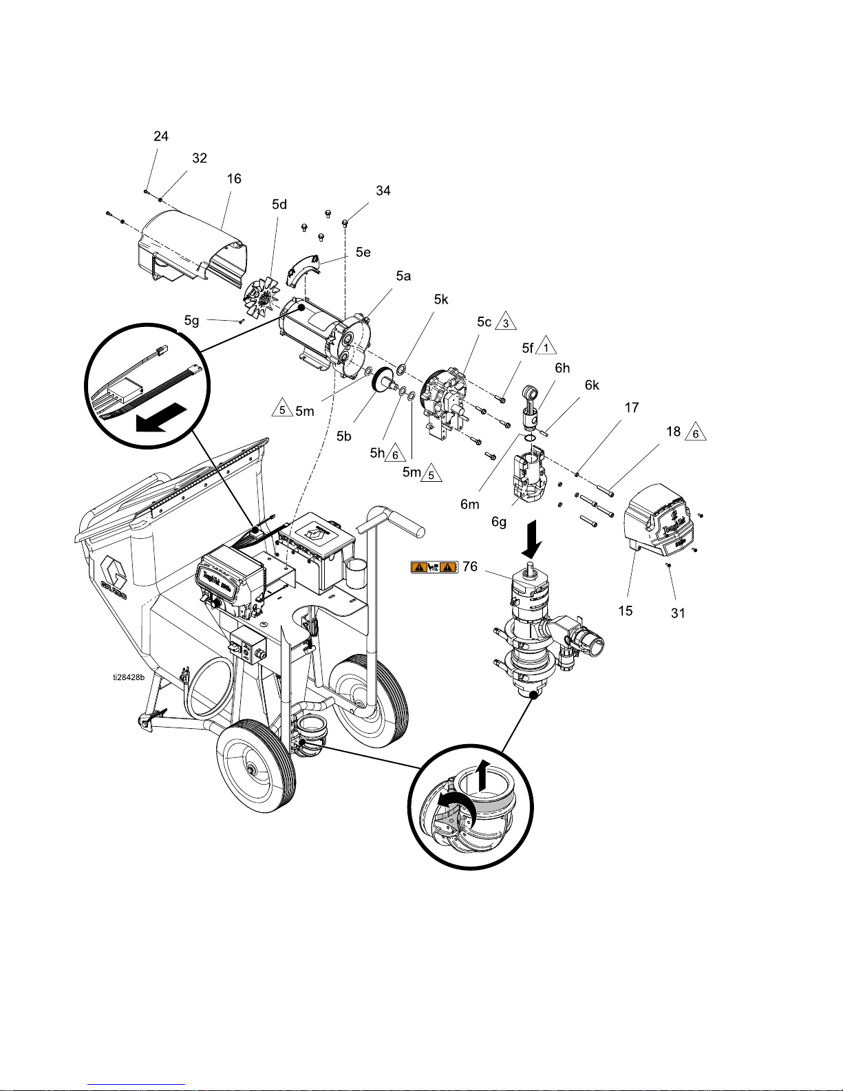
Parts
Driver Driver
Driver
and and
and
Motor Motor
Motor
34 3A3437F
Page 35

Parts
Ref. Ref.
Ref.
Part Part
Part
Description Description
Description
Qty. Qty.
Qty.
5a 5a
5a
– ––– ––– ––– ––– –
–
MOTOR, MOTOR,
MOTOR,
electric electric
electric
1 1
1
5b 5b
5b
– ––– ––– ––– ––– –
–
GEAR, GEAR,
GEAR,
combination combination
combination
1 1
1
5c 5c
5c
– ––– ––– ––– ––– –
–
HOUSING, HOUSING,
HOUSING,
drive drive
drive
1 1
1
5d 5d
5d
15D088 15D088
15D088
FAN, FAN,
FAN,
motor motor
motor
1 1
1
5e 5e
5e
278075 278075
278075
BRACKET, BRACKET,
BRACKET,
wire wire
wire
1 1
1
5f 5f
5f
15C753 15C753
15C753
SCREW, SCREW,
SCREW,
mach, mach,
mach,
hex hex
hex
wash wash
wash
hd hd
hd
5 5
5
5g 5g
5g
115477 115477
115477
SCREW, SCREW,
SCREW,
mach, mach,
mach,
torx torx
torx
pan pan
pan
hd hd
hd
1 1
1
5h 5h
5h
114699 114699
114699
WASHER, WASHER,
WASHER,
thrust thrust
thrust
1 1
1
5k 5k
5k
116192 116192
116192
WASHER, WASHER,
WASHER,
thrust thrust
thrust
1 1
1
5m 5m
5m
114672 114672
114672
WASHER, WASHER,
WASHER,
thrust thrust
thrust
2 2
2
6g 6g
6g
– ––– ––– ––– ––– –
–
HOUSING, HOUSING,
HOUSING,
bearing bearing
bearing
1 1
1
6h 6h
6h
287395 287395
287395
ROD, ROD,
ROD,
connecting connecting
connecting
1 1
1
6k 6k
6k
183210 183210
183210
PIN, PIN,
PIN,
str, str,
str,
hdls hdls
hdls
1 1
1
6m 6m
6m
119778 119778
119778
SPRING, SPRING,
SPRING,
retaining retaining
retaining
1 1
1
15 1515†
– ––– ––– ––– ––– –
–
COVER, COVER,
COVER,
front, front,
front,
plastic, plastic,
plastic,
painted painted
painted
1 1
1
16 1616†
– ––– ––– ––– ––– –
–
SHIELD, SHIELD,
SHIELD,
motor, motor,
motor,
painted painted
painted
1 1
1
Ref. Ref.
Ref.
Part Part
Part
Description Description
Description
Qty. Qty.
Qty.
17 17
17
106115 106115
106115
WASHER, WASHER,
WASHER,
lock lock
lock
(hi (hi
(hi
collar) collar)
collar)
4 4
4
18 18
18
114666 114666
114666
SCREW, SCREW,
SCREW,
cap, cap,
cap,
socket socket
socket
head head
head
4 4
4
24 24
24
119250 119250
119250
SCREW, SCREW,
SCREW,
shoulder shoulder
shoulder
2 2
2
31 31
31
118444 118444
118444
SCREW, SCREW,
SCREW,
mach, mach,
mach,
slot, slot,
slot,
hex hex
hex
wash wash
wash
hd hd
hd
4 4
4
32 32
32
276980 276980
276980
GROMMET, GROMMET,
GROMMET,
cover cover
cover
2 2
2
34 34
34
– ––– ––– ––– ––– –
–
SCREW, SCREW,
SCREW,
cap, cap,
cap,
hex hex
hex
hd hd
hd
6 6
6
76 76
76
▲ ▲
▲
192840 192840
192840
LABEL, LABEL,
LABEL,
warning warning
warning
1 1
1
▲ ▲
▲
Replacement Replacement
Replacement
Danger Danger
Danger
and and
and
Warning Warning
Warning
labels, labels,
labels,
tags, tags,
tags,
and and
and
cards cards
cards
are are
are
available available
available
at atatno no
no
cost. cost.
cost.
†
See See
See
List List
List
of ofofKits Kits
Kits
table. table.
table.
1
Torque Torque
Torque
to toto190–210 190–210
190–210
in inin- --lb lblb(21.4–23.7 (21.4–23.7
(21.4–23.7
N●m). N●m).
N●m).
3
Apply Apply
Apply
lubricant lubricant
lubricant
to totoall all
all
gear gear
gear
teeth teeth
teeth
proportionally. proportionally.
proportionally.
5
Copper Copper
Copper
colored colored
colored
washer. washer.
washer.
6
Steel Steel
Steel
colored colored
colored
washer. washer.
washer.
List List
List
of of
of
Kits Kits
Kits
Kit Kit
Kit
Description Description
Description
Kit Kit
Kit
Contents: Contents:
Contents:
Ref. Ref.
Ref.
# ##(Qty.) (Qty.)
(Qty.)
17J711 17J711
17J711
F340e F340e
F340e
pump pump
pump
motor motor
motor
5 55(1) (1)
(1)
Includes Includes
Includes
5a 5a5a- --5h, 5h,
5h,
5k, 5k,
5k,
5m 5m
5m
17J704 17J704
17J704
Front Front
Front
cover cover
cover
kit kit
kit
15 15
15
(1), (1),
(1),
31 31
31
(4), (4),
(4),
S340e S340e
S340e
Label Label
Label
(1), (1),
(1),
F340e F340e
F340e
label label
label
(1) (1)
(1)
287282 287282
287282
Motor Motor
Motor
shield shield
shield
kit kit
kit
16 16
16
(1), (1),
(1),
24 24
24
(2), (2),
(2),
32 32
32
(2) (2)
(2)
3A3437F 35
Page 36
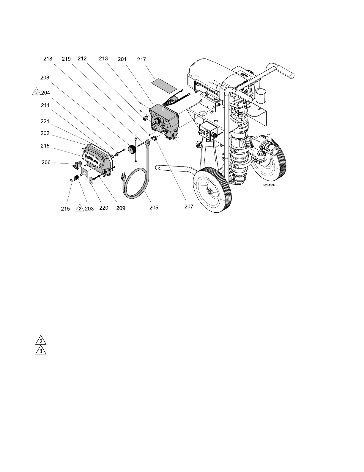
Parts
Control Control
Control
Box Box
Box
Ref. Ref.
Ref.
Part Part
Part
Description Description
Description
Qty. Qty.
Qty.
201 201
201
– ––– ––– ––– ––– –
–
CONTROL, CONTROL,
CONTROL,
board, board,
board,
50 5050amp amp
amp
1 1
1
202 202
202
– ––– ––– ––– ––– –
–
COVER, COVER,
COVER,
control, control,
control,
ultra, ultra,
ultra,
std std
std
1 1
1
203 203
203
116167 116167
116167
KNOB, KNOB,
KNOB,
potentiometer potentiometer
potentiometer
1 1
1
204 204
204
256219 256219
256219
POTENTIOMETER, POTENTIOMETER,
POTENTIOMETER,
assembly assembly
assembly
1 1
1
205 205
205
15H064 15H064
15H064
CORD, CORD,
CORD,
power power
power
1 1
1
206 206
206
15D527 15D527
15D527
SWITCH, SWITCH,
SWITCH,
rocker, rocker,
rocker,
240V 240V
240V
1 1
1
207 207
207
16T547 16T547
16T547
ADAPTER, ADAPTER,
ADAPTER,
cord cord
cord
1 1
1
208 208
208
– ––– ––– ––– ––– –
–
COIL, COIL,
COIL,
lter lter
lter
1 1
1
209 209
209
16Z019 16Z019
16Z019
HARNESS, HARNESS,
HARNESS,
wiring, wiring,
wiring,
with with
with
light light
light
1 1
1
211 211
211
15C973 15C973
15C973
GASKET GASKET
GASKET
1 1
1
212 212
212
16T483 16T483
16T483
PLUG, PLUG,
PLUG,
hole, hole,
hole,
switch switch
switch
1 1
1
Ref. Ref.
Ref.
Part Part
Part
Description Description
Description
Qty. Qty.
Qty.
213 213
213
– ––– ––– ––– ––– –
–
PLUG, PLUG,
PLUG,
nylon nylon
nylon
2 2
2
215 215
215
– ––– ––– ––– ––– –
–
LABEL LABEL
LABEL
1 1
1
216 216
216
16Y786 16Y786
16Y786
LABEL, LABEL,
LABEL,
control, control,
control,
elec, elec,
elec,
std std
std
1 1
1
217 217
217
▲ ▲
▲
16T784 16T784
16T784
LABEL, LABEL,
LABEL,
warning, warning,
warning,
EN/FR/ES EN/FR/ES
EN/FR/ES
1 1
1
218 218
218
16U215 16U215
16U215
SCREW, SCREW,
SCREW,
phillips, phillips,
phillips,
pan pan
pan
hd, hd,
hd,
plastite plastite
plastite
1 1
1
219 219
219
114391 114391
114391
SCREW, SCREW,
SCREW,
grounding grounding
grounding
1 1
1
220 220
220
– ––– ––– ––– ––– –
–
LABEL, LABEL,
LABEL,
control, control,
control,
F340e, F340e,
F340e,
Proguard Proguard
Proguard
1 1
1
221 221
221
– ––– ––– ––– ––– –
–
GASKET, GASKET,
GASKET,
housing, housing,
housing,
motor, motor,
motor,
control, control,
control,
F340e F340e
F340e
1 1
1
2
Torque Torque
Torque
to toto10–15 10–15
10–15
in inin- --lb lblb(1.1–1.7 (1.1–1.7
(1.1–1.7
N●m). N●m).
N●m).
3
Torque Torque
Torque
to toto30–35 30–35
30–35
in inin- --lb lblb(3.3–3.9 (3.3–3.9
(3.3–3.9
N●m). N●m).
N●m).
▲ ▲
▲
Replacement Replacement
Replacement
Danger Danger
Danger
and and
and
Warning Warning
Warning
labels, labels,
labels,
tags, tags,
tags,
and and
and
cards cards
cards
are are
are
available available
available
at atatno no
no
cost. cost.
cost.
NOTE: NOTE:
NOTE:
All All
All
Control Control
Control
Box Box
Box
Parts Parts
Parts
listed listed
listed
above above
above
are are
are
included included
included
in ininboth both
both
the the
the
120V 120V
120V
Motor Motor
Motor
Control Control
Control
Module Module
Module
Kit Kit
Kit
(17J702) (17J702)
(17J702)
and and
and
230V 230V
230V
Motor Motor
Motor
Control Control
Control
Module Module
Module
Kit Kit
Kit
(17J755). (17J755).
(17J755).
36 3A3437F
Page 37
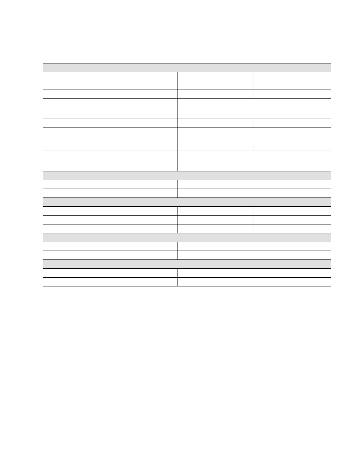
TechnicalSpecications
Technical Technical
Technical
Specications Specications
Specications
ToughTek ToughTek
ToughTek
S340e S340e
S340e
Sprayer Sprayer
Sprayer
U.S. U.S.
U.S.
Metric Metric
Metric
MaximumFluidWorkingPressure600psi4.1MPa,41Bar
StrokeLength
2.25in.
57mm
Maximumpumpspeed(Donotexceedmaximum
recommendedspeedofuidpumptoprevent
prematurepumpwear)
150cyclesperminute
Weight(dry)
210lb95kg
WettedParts
Stainlesssteel,platedsteel,carbide,urethane,PTFE,
UHMWPE,LLDPE,aluminum,neoprene
FluidinletSize
3.0in.7.6cm
FluidOutletSize1.5in.npt(f)with35mmfemalemortarcoupling
NorthAmericansystems:1.5in.npt(f)with
1.5in.malecamlock
PowerRequirements
120VModels
120VAC,singlephase,50/60Hz
230VModels
230VAC,singlephase,50/60Hz
HoseRequirements
MinimumPressure600psi4.1MPa,41Bar
MinimumHoseDiameter1.0in.2.5cm
MinimumHoseLength
25ft
7.6m
PowerRequirements
120VModels1phase,50/60Hz
230VModels1phase,50/60Hz
NoiseLevel
SoundPower90.4dBa*
SoundPressure80.5dBa*
*perISO3744;measuredat3.1ft
3A3437F 37
Page 38

Graco Graco
Graco
Standard Standard
Standard
Warranty Warranty
Warranty
GracowarrantsallequipmentreferencedinthisdocumentwhichismanufacturedbyGracoandbearingits
nametobefreefromdefectsinmaterialandworkmanshiponthedateofsaletotheoriginalpurchaserforuse.
Withtheexceptionofanyspecial,extended,orlimitedwarrantypublishedbyGraco,Gracowill,foraperiodof
twelvemonthsfromthedateofsale,repairorreplaceanypartoftheequipmentdeterminedbyGracotobe
defective.Thiswarrantyappliesonlywhentheequipmentisinstalled,operatedandmaintainedinaccordance
withGraco’swrittenrecommendations.
Thiswarrantydoesnotcover,andGracoshallnotbeliableforgeneralwearandtear,oranymalfunction,
damageorwearcausedbyfaultyinstallation,misapplication,abrasion,corrosion,inadequateorimproper
maintenance,negligence,accident,tampering,orsubstitutionofnon-Gracocomponentparts.NorshallGraco
beliableformalfunction,damageorwearcausedbytheincompatibilityofGracoequipmentwithstructures,
accessories,equipmentormaterialsnotsuppliedbyGraco,ortheimproperdesign,manufacture,installation,
operationormaintenanceofstructures,accessories,equipmentormaterialsnotsuppliedbyGraco.
Thiswarrantyisconditionedupontheprepaidreturnoftheequipmentclaimedtobedefectivetoanauthorized
Gracodistributorforvericationoftheclaimeddefect.Iftheclaimeddefectisveried,Gracowillrepairorreplace
freeofchargeanydefectiveparts.Theequipmentwillbereturnedtotheoriginalpurchasertransportation
prepaid.Ifinspectionoftheequipmentdoesnotdiscloseanydefectinmaterialorworkmanship,repairswillbe
madeatareasonablecharge,whichchargesmayincludethecostsofparts,labor,andtransportation.
THIS THIS
THIS
WARRANTY WARRANTY
WARRANTY
IS ISISEXCLUSIVE, EXCLUSIVE,
EXCLUSIVE,
AND AND
AND
IS IS
IS
IN IN
IN
LIEU LIEU
LIEU
OF OF
OF
ANY ANY
ANY
OTHER OTHER
OTHER
WARRANTIES, WARRANTIES,
WARRANTIES,
EXPRESS EXPRESS
EXPRESS
OR OR
OR
IMPLIED, IMPLIED,
IMPLIED,
INCLUDING INCLUDING
INCLUDING
BUT BUT
BUT
NOT NOT
NOT
LIMITED LIMITED
LIMITED
TO TO
TO
WARRANTY WARRANTY
WARRANTY
OF OF
OF
MERCHANTABILITY MERCHANTABILITY
MERCHANTABILITY
OR OR
OR
WARRANTY WARRANTY
WARRANTY
OF OF
OF
FITNESS FITNESS
FITNESS
FOR FOR
FOR
A AAPARTICULAR PARTICULAR
PARTICULAR
PURPOSE. PURPOSE.
PURPOSE.
Graco’ssoleobligationandbuyer’ssoleremedyforanybreachofwarrantyshallbeassetforthabove.The
buyeragreesthatnootherremedy(including,butnotlimitedto,incidentalorconsequentialdamagesforlost
prots,lostsales,injurytopersonorproperty,oranyotherincidentalorconsequentialloss)shallbeavailable.
Anyactionforbreachofwarrantymustbebroughtwithintwo(2)yearsofthedateofsale.
GRACO GRACO
GRACO
MAKES MAKES
MAKES
NO NO
NO
WARRANTY, WARRANTY,
WARRANTY,
AND AND
AND
DISCLAIMS DISCLAIMS
DISCLAIMS
ALL ALL
ALL
IMPLIED IMPLIED
IMPLIED
WARRANTIES WARRANTIES
WARRANTIES
OF OF
OF
MERCHANTABILITY MERCHANTABILITY
MERCHANTABILITY
AND AND
AND
FITNESS FITNESS
FITNESS
FOR FOR
FOR
A AAPARTICULAR PARTICULAR
PARTICULAR
PURPOSE, PURPOSE,
PURPOSE,
IN IN
IN
CONNECTION CONNECTION
CONNECTION
WITH WITH
WITH
ACCESSORIES, ACCESSORIES,
ACCESSORIES,
EQUIPMENT, EQUIPMENT,
EQUIPMENT,
MATERIALS MATERIALS
MATERIALS
OR OR
OR
COMPONENTS COMPONENTS
COMPONENTS
SOLD SOLD
SOLD
BUT BUT
BUT
NOT NOT
NOT
MANUFACTURED MANUFACTURED
MANUFACTURED
BY BY
BY
GRACO. GRACO.
GRACO.
Theseitemssold,butnot
manufacturedbyGraco(suchaselectricmotors,switches,hose,etc.),aresubjecttothewarranty,ifany,of
theirmanufacturer.Gracowillprovidepurchaserwithreasonableassistanceinmakinganyclaimforbreachof
thesewarranties.
InnoeventwillGracobeliableforindirect,incidental,specialorconsequentialdamagesresultingfromGraco
supplyingequipmenthereunder,orthefurnishing,performance,oruseofanyproductsorothergoodssold
hereto,whetherduetoabreachofcontract,breachofwarranty,thenegligenceofGraco,orotherwise.
FORGRACOCANADACUSTOMERS
ThePartiesacknowledgethattheyhaverequiredthatthepresentdocument,aswellasalldocuments,notices
andlegalproceedingsenteredinto,givenorinstitutedpursuantheretoorrelatingdirectlyorindirectlyhereto,be
drawnupinEnglish.Lespartiesreconnaissentavoirconvenuquelarédactionduprésentedocumentseraen
Anglais,ainsiquetousdocuments,avisetprocéduresjudiciairesexécutés,donnésouintentés,àlasuitedeou
enrapport,directementouindirectement,aveclesprocéduresconcernées.
Graco Graco
Graco
Information Information
Information
ForthelatestinformationaboutGracoproducts,visitwww.graco.com.
Forpatentinformation,seewww.graco.com/patents.
To To
To
place place
place
an an
an
order, order,
order,
contactyourGracoDistributororcalltoidentifythenearestdistributor.
Phone: Phone:
Phone:
612-623-6921or ororToll Toll
Toll
Free: Free:
Free:
1-800-328-0211Fax: Fax:
Fax:
612-378-3505
Allwrittenandvisualdatacontainedinthisdocumentreectsthelatestproductinformationavailableatthetimeofpublication.
Gracoreservestherighttomakechangesatanytimewithoutnotice.
OriginalInstructions.ThismanualcontainsEnglish.MM3A3437 3A3437
3A3437
Graco Graco
Graco
Headquarters: Headquarters:
Headquarters:
Minneapolis
International International
International
Ofces: Ofces:
Ofces:
Belgium,China,Japan,Korea
GRACO GRACO
GRACO
INC. INC.
INC.
AND AND
AND
SUBSIDIARIES SUBSIDIARIES
SUBSIDIARIES
• ••P.O. P.O.
P.O.
BOX BOX
BOX
1441 1441
1441
• ••MINNEAPOLIS MINNEAPOLIS
MINNEAPOLIS
MN MN
MN
55440-1441 55440-1441
55440-1441
• ••USA USA
USA
Copyright Copyright
Copyright
2016, 2016,
2016,
Graco Graco
Graco
Inc. Inc.
Inc.
All All
All
Graco Graco
Graco
manufacturing manufacturing
manufacturing
locations locations
locations
are are
are
registered registered
registered
to totoISO ISO
ISO
9001. 9001.
9001.
www.graco.com
RevisionF–October2018
 Loading...