

Graco ToughTek M680a Operation - Repair - Parts
Operation, Repair, Parts
WLD
ToughTek® M680a CS Mortar
3A5275B
Spray er
Sprayer for water-based cementitious materials. Not for use with solvent-borne materials.
For professional use only.
600 psi (4.1 MPa, 41 bar) Maximum Fluid Working
Pressure
150 psi (1.0 MPa, 10 bar) Maximum Air Inlet Pressure
60 psi (0.41 MPa, 4.1 bar) Maximum Pump Air Regulator
Pressure
See page 2 for model information, including model
numbers and approvals.
Important Safety Instructions
Read all warnings and instructions in this
manual. Save these instructions.
EN
II 2 G
c IIA T5

Related Manuals
II 2 G
c IIA T5
Contents
Related Manuals . . . . . . . . . . . . . . . . . . . . . . . . . . . 2
Models . . . . . . . . . . . . . . . . . . . . . . . . . . . . . . . . . . . 2
Spray P ackages . . . . . . . . . . . . . . . . . . . . . . . . . 3
Warnings . . . . . . . . . . . . . . . . . . . . . . . . . . . . . . . . . 5
Changing Materials . . . . . . . . . . . . . . . . . . . . . . . 7
Component Identification . . . . . . . . . . . . . . . . . . . . 8
Overview . . . . . . . . . . . . . . . . . . . . . . . . . . . . . . . 8
System Components . . . . . . . . . . . . . . . . . . . . . . 9
Installation . . . . . . . . . . . . . . . . . . . . . . . . . . . . . . . 10
Grounding . . . . . . . . . . . . . . . . . . . . . . . . . . . . . 10
Setup . . . . . . . . . . . . . . . . . . . . . . . . . . . . . . . . . . . . 11
Operation . . . . . . . . . . . . . . . . . . . . . . . . . . . . . . . . 12
Pressure Relief Procedure . . . . . . . . . . . . . . . . 12
Wet Out the System . . . . . . . . . . . . . . . . . . . . . 13
Mix the Material . . . . . . . . . . . . . . . . . . . . . . . . . 15
Prime with Material . . . . . . . . . . . . . . . . . . . . . . 15
Spray . . . . . . . . . . . . . . . . . . . . . . . . . . . . . . . . . 17
Flush the Equipment . . . . . . . . . . . . . . . . . . . . . 19
Disassemble and Clean the Pump (Daily) . . . . 22
Shutdown . . . . . . . . . . . . . . . . . . . . . . . . . . . . . 25
Maintenance . . . . . . . . . . . . . . . . . . . . . . . . . . . . . . 26
Preventive Maintenance . . . . . . . . . . . . . . . . . . 26
Daily Maintenance . . . . . . . . . . . . . . . . . . . . . . . 26
Corrosion Protection . . . . . . . . . . . . . . . . . . . . . 26
Cart Maintenance . . . . . . . . . . . . . . . . . . . . . . . 26
Troubleshooting . . . . . . . . . . . . . . . . . . . . . . . . . . . 27
Repair . . . . . . . . . . . . . . . . . . . . . . . . . . . . . . . . . . . 29
Replace Pump Components . . . . . . . . . . . . . . . 29
Replace Air Motor . . . . . . . . . . . . . . . . . . . . . . . 29
Replace Pump Lower . . . . . . . . . . . . . . . . . . . . 29
Parts . . . . . . . . . . . . . . . . . . . . . . . . . . . . . . . . . . . . 30
ToughTek M680a CS Systems . . . . . . . . . . . . . 30
Pump Lower (25C964) . . . . . . . . . . . . . . . . . . . 32
Air Controls . . . . . . . . . . . . . . . . . . . . . . . . . . . . 33
Hose Bundle Repair Parts . . . . . . . . . . . . . . . . . 34
Tec hnical Specifications . . . . . . . . . . . . . . . . . . . . 35
Graco Standard Warranty . . . . . . . . . . . . . . . . . . . 36
Graco Information . . . . . . . . . . . . . . . . . . . . . . . . . 36
Related Manuals
Manuals are available at www.graco.com.
Component manuals in English:
Manual Description
332651 Mortar Spraying Tips
332767 Mortar Spraying Applicators
332768
312796
™
680 Applicator
HTX
®
Air Motors
NXT
Models
Model Description
25M572 ToughTek M680a CS Mortar Sprayer ✓✓
26A489 Flex Applicator Spray Package ✓
26A490 Pole Applicator Spray Package ✓
26A491 HTX Applicator Spray Package ✓
2 3A5275B
Spray Packages
WLD
ti31706a
WLD
WLD
Package Included Applicator
Part Description Part Applicator Type
27A489 System, M680a CS, Flex Applicator, Package 24T947 Flex
27A490 System, M680a CS, Pole Applicator, Package 24T946 Pole
27A491 System, M680a CS, HTX Applicator, Package 24U209 HTX
Packages include:
• (1) ToughTek M680a CS Mortar Sprayer
• (1) Fluid hose bundle
• (2) Air hose bundle
• (1) Applicator camlock reducer
• (1) Applicator (see above table and Applicators, page 4)
Models
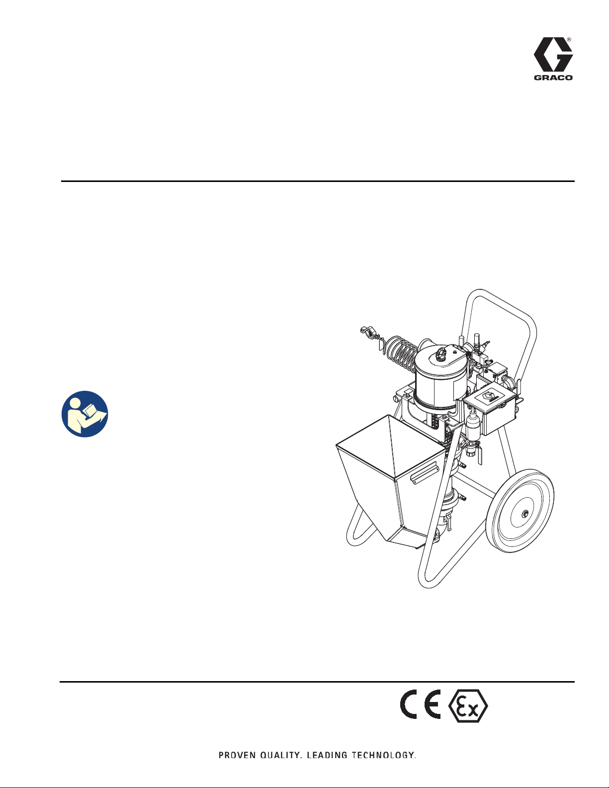
Fluid Hose Bundle (27A004)
Includes 50 ft of 1 3/8 in. mortar hose with 1.5 in.
camlock connections.
FIG. 1: Fluid Hose Bundle
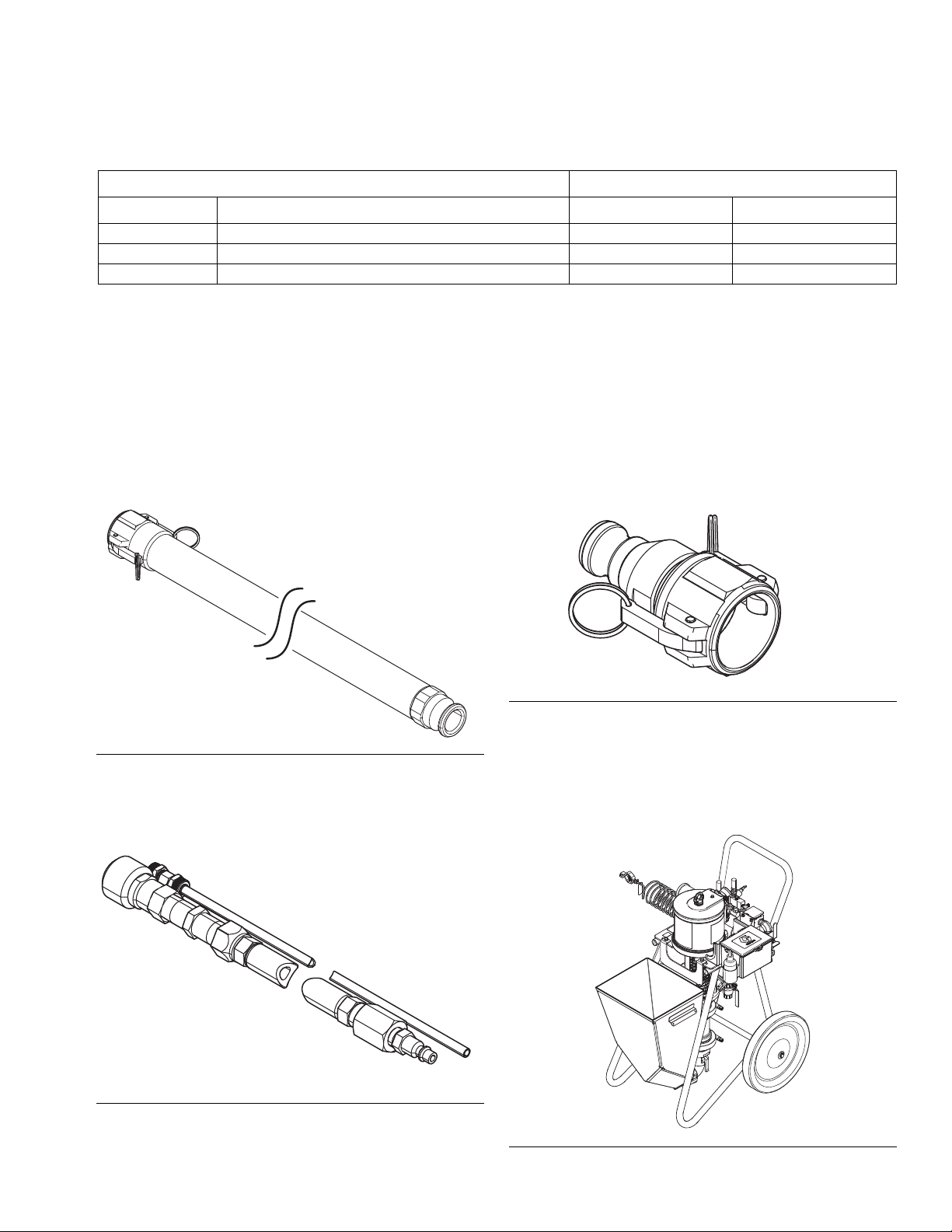
Air Hose Bundle (24T852)
Includes 25 ft of air hose with 1/4 in. quick disconnect air
fittings and 25 ft of air pilot line.
Applicator Camlock Reducer (17G767)
Connects a 1.5 in. male camlock hose outlet to a 1 in.
female camlock fitting on applicator.
FIG. 3: Applicator Camlock Reducer
ToughTek M680a CS Mortar Sprayer
(25M572)
Includes sprayer with 1.5 in. male camlock fluid outlet,
1/4 in. air quick disconnect, air pilot line connection, and
3/4 npt air supply inlet.
FIG. 2: Air Hose Bundle
FIG. 4: ToughTek M680a CS Mortar Sprayer
3A5275B 3
Models
WLD
WLD
WLD
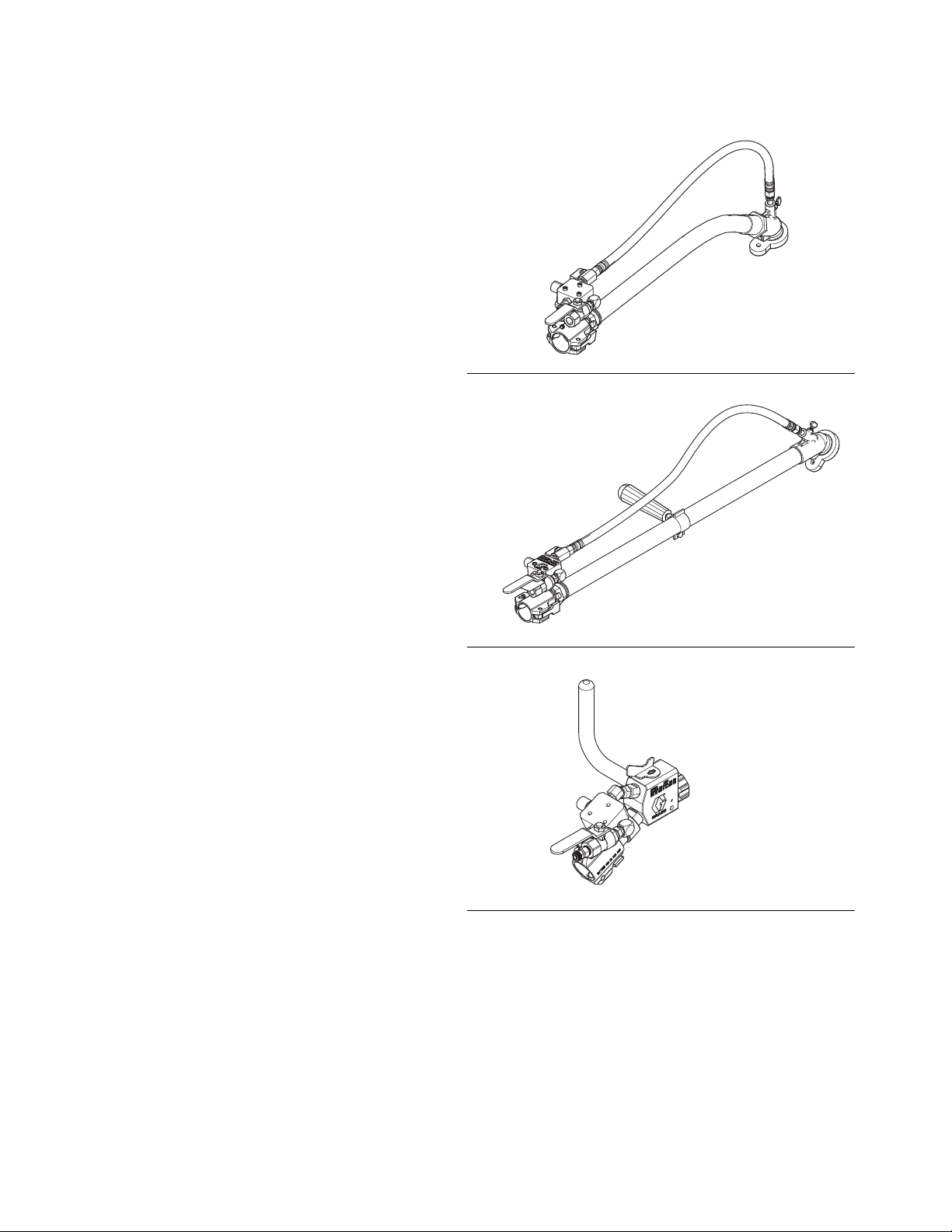
Applicators
Flex Applicator
The flex applicator is for use in low pressure spraying
of materials that packout easily and will be
finish-troweled.
Includes 23 in. (58 cm) fle xible hose with a 1 in. camloc k
fluid inlet, angled spra y head, spray air volume control,
spray air shut off valve, and motor pilot signal control
valve; an adjustable-position center air injection tube, a
rubber tip retainer, and three tip sizes.
Pole Applicator
The pole applicator is for use in low-pressure spraying
in long-reach, open areas, using materials that packout
easily and will be finish-troweled. The pole applicator is
similar to the flex applicator but includes a pipe instead
of a hose.
FIG. 5: Flex Applicator
Includes a 30 in. (76 cm) aluminum pipe with a 1 in.
camlock fluid inlet, angled spray head, spray air volume
control, spray air shut-off valve, and motor pilot signal
control valve; an adjustable-position center air injection
tube, a rubber tip retainer, and three tip sizes.
HTX 680 Applicator
The HTX 680 applicator is for use in medium-pressure
spraying of materials that do not packout easily.
The HTX 680 uses venturi-type air injection f luid nozzles
and an aluminum screw on tip retainer. The applicator
includes a 1 in. camlock fluid inlet, angled alum inum
spray head, spray air volume control, spray air shut off
valve , and motor pilot signal contr ol valve. Also includes
four nozzle sizes, a Fine Finish adapter, and four Fine
Finish tips.
FIG. 6: Pole Applicator
FIG. 7: HTX 680 Applicator
4 3A5275B
Warnings
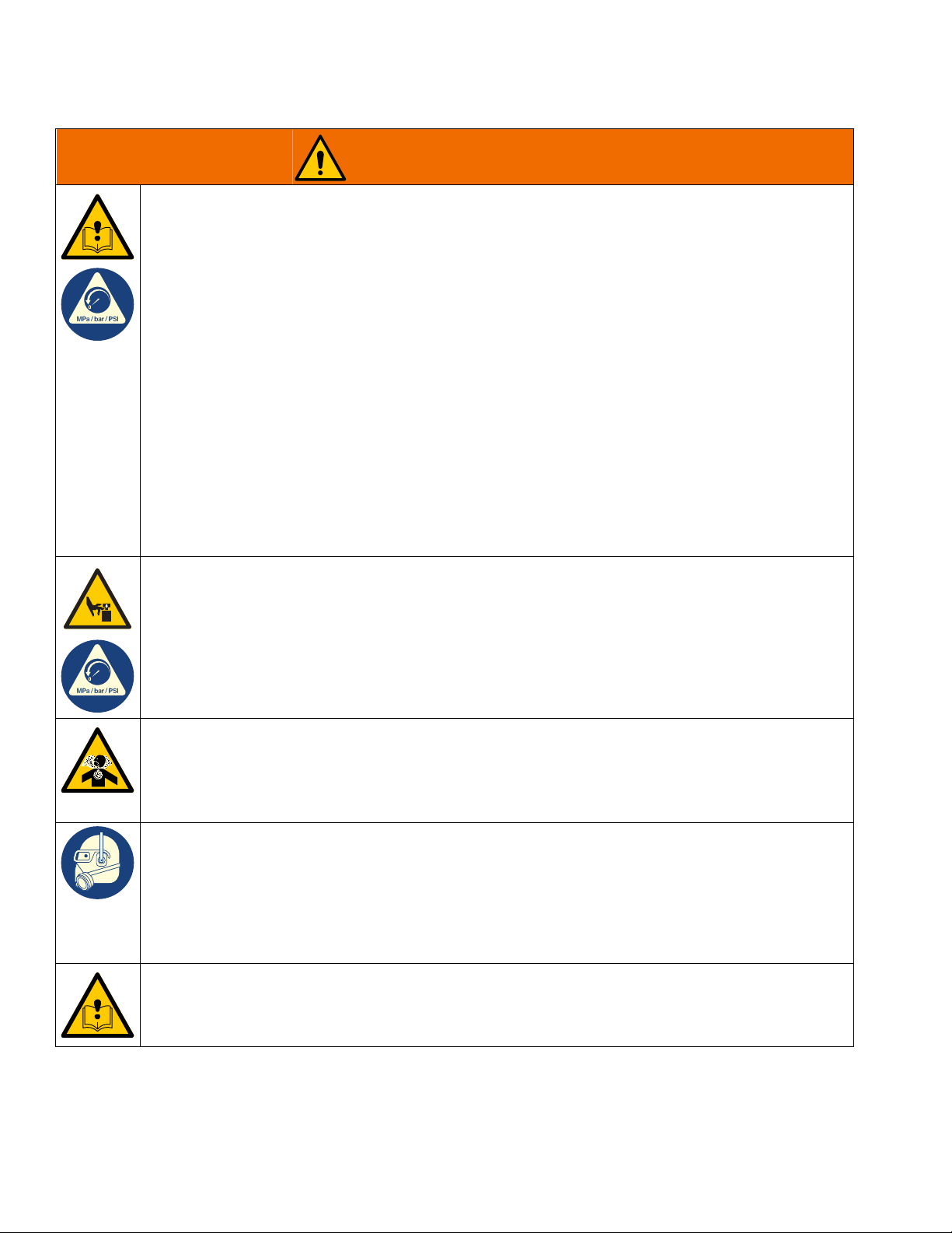
WARNING
Warnings
The following warnings are for the setup, use, grounding, maintenance, and repair of this equipment. The
exclamation point symbol alerts you to a general warning and the hazard symbols refer to procedure-specific risks.
When these symbols appear in the body of this manual or on warning labels, refer back to these Warnings.
Product-specific hazard symbols and warnings not covered in this section may appear throughout the body of this
manual where applicable.
FIRE AND EXPLOSION HAZARD
Flammable fumes, such as solvent and paint fumes, in work area can ignite or explode. Paint or solvent flowing through the equipment can cause static sparking. To help prevent fire and explosion:
• Use equipment only in well-ventilated area.
• Eliminate all ignition sources; such as pilot lights, cigarettes, portable electric lamps, a nd plastic drop
cloths (potential static sparking).
• Ground all equipment in the work area. See Grounding instructions.
• Never spray or flush solvent at high pressure.
• Keep work area free of debris, including solvent, rags and gasoline.
• Do not plug or unplug power cords, or turn power or light switches on or off when flammable fumes
are present.
• Use only grounded hoses.
• Hold gun firmly to side of grounded pail when t riggering into pail. Do not u se p ail l iner s un less they
are anti-static or conductive.
• Stop operation immediately if static sparking occurs or y ou feel a shock. Do not use equipment until
you identify and correct the problem.
• Keep a working fire extinguisher in the work area.
SKIN INJECTION HAZARD
High-pressure fluid from dispensing device, hose leaks, or ruptured components will pierce skin. This
may look like just a cut, but it is a serious injury that can result in amputation. Get immediate surgical
treatment.
• Do not point dispensing device at anyone or at any part of the body.
• Do not put your hand over the fluid outlet.
• Do not stop or deflect leaks with your hand, body, glove, or rag.
• Follow the Pressure Reli ef Procedure when y ou stop dispensing and bef ore cleaning, checking , or
servicing equipme nt .
• Tighten all fluid connections before operating the equipment.
• Check hoses and couplings daily. Replace worn or damaged parts immediately.
3A5275B 5
Warnings
WARNING
EQUIPMENT MISUSE HAZARD
Misuse can cause death or serious injury.
• Do not operate the unit when fatigued or under the influence of drugs or alcohol.
• Do not exceed the maximum working pressure or temperature rating of the lowest rated system component. See Technical Specifications in all equipment manuals.
• Use fluids that are compatible with equipment wetted parts. See Technical Specificat ions in all
equipment manuals. Read material manufacturer’s warnings. For complete information about your
material, request Safety Data Sheets (SDSs) from distributor or retailer.
• Do not leave the work area while equipment is energized or under pressure.
• Turn off all equipment and follow the Pressure Relief Procedure when equipment is not in use.
• Check equipment daily. Repair or replace worn or damaged parts immediately with genuine manufacturer’s replacement parts only.
• Do not alter or modify equipment. Alter ations or modifications ma y void agency approv als and create
safety hazards.
• Make sure all equipment is rated and approved for the environment in which you are using it.
• Use equipment only for its intended purpose. Call your distributor for information.
• Route hoses and cables away from traffic areas, sharp edges, moving parts, and hot surfaces.
• Do not kink or over bend hoses or use hoses to pull equipment.
• Keep children and animals away from work area.
• Comply with all applicable safety regulations.
MOVING PARTS HAZARD
Moving parts can pinch, cut or amputate fingers and other body parts.
• Keep clear of moving parts.
• Do not operate equipment with protective guards or covers removed.
• Pressurized equipment can start without warning. Before chec king, moving, or servicing equipment,
follow the Pressure Relief Procedure and disconnect all power sources.
TOXIC FLUID OR FUMES HAZARD
Toxic fluids or fumes can cause serious injury or death if splashed in the eyes or on skin, inhaled, or
swallowed.
• Read Safety Data Sheets (SDSs) to know the specific hazards of the fluids you are using.
• Store hazardous fluid in approved containers, and dispose of it according to applicable guidelines.
PERSONAL PROTECTIVE EQUIPMENT
Wear appropriate protective equipment when in the work area to help prevent serious injury, including
eye injury, hearing loss, inhalation of toxic fumes, and burns. Protective equipment includes but is not
limited to:
• Protective eyewear, and hearing protection.
• Respirators, protective clothing, and gloves as recommended by the manufacturer of the pumped
material.
SUCTION HAZARD
Powerful suction can cause serious injury.
• Never place hands near the pump fluid inlet when pump is operating or pressurized.
6 3A5275B

Changing Materials
NOTICE
Changing the material types used in your equipment
requires special attention to a v oid e quipment damage
and downtime.
• When changing materials, flush the equipment
multiple times to ensure it is thoroughly clean.
• Always clean the int ernal pump components after
flushing.
• Check with your material manufacturer for
chemical compatibility.
Warnings
3A5275B 7
Component Identification
WLE
$&
$$
$%
$'
$-
5
3
)
1
&
$
<
%
'
+
(
;
/
-
*
8
0
:
Component Identification
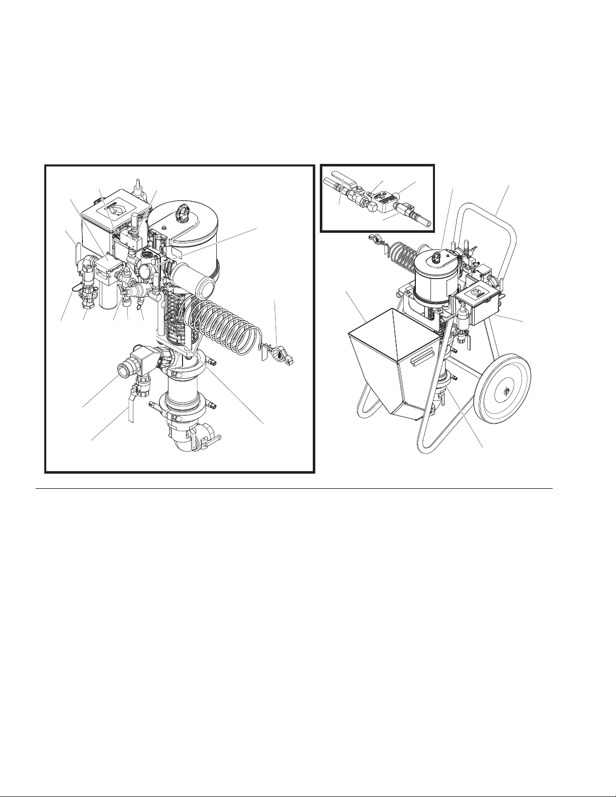
Overview
FIG. 8: Typical Installation
Key:
AA Material Hopper
AB Air Motor
AC Lower
AD Cart
AJ System Air Inlet
A Air Inlet, 3/4 npt(f) Claw (Chicago) Fittings
B Bleed Type Master Valve (required)
C Air Pressure Relief Valve
D Air Filter (40 micron)
E Motor Air Pressure Gauge
F Motor Air Pressure Regulator Adjustment Knob
G* Air Motor Pilot Ball Valve (starts/stops air motor
from applicator)
H Motor Air Pilot Valve
J Pressure Relief Ball Valve
L Grounding Wire, required (see Grounding, page
10)
M* Needle Valve for Air Assist Flow Control
N Air Supply Quick Disconnect to Applicator Air
Inlet Quick Disconnect
P Fluid Outlet, 1.5 in. Male Camlock Fitting
R Packing Nut/Wet Cup under Spring Guard
U* Air Assist Shutoff Ball Valve
W* Applicator Air Inlet Quick Disconnect
X Pilot Valve Signal (to Applicator)
Y Whip Check Hose Safety Cable
*Part of applicator
8 3A5275B

Component Identification
System Components
NOTE: System requires use of an applicator with an air
pilot line and air pilot valv e to oper ate . See Applicators,
page 4 for compatible applicators.
*Required system components
To avoid tip ping o v er, ensure cart is on a flat and lev e l
surface. Failure to do so could result in injury or
equipment damage.
*Bleed Type Master Air Valve (B)
• Be sure the valve is easily accessible from the
applicator.
• Required in your system to relieve air trapped
between it and the air motor when the valve is
closed.
- Open to supply air to the motor.
- Close to shut off air to the motor and bleed any
trapped air from the motor.
*Air Pressure Relief Valve (C)
Air Filter (D)
Removes harmful dirt and water from compressed air
supply.
Air Regulator Adjustment Knob (F)
Adjusts air pressure to the motor and fluid outlet
pressure of the pump. Read air pressure on gauge (E).
*Pressure Relief Ball Valve (J)
Open valve to relieve pressure if pump or hose packout
occurs. Close valve when spraying.
NOTICE
To prevent material hardening in the pressure relief
ball valve (J), flush the valve after each use. See
Flush the Equipment, page 19.
To help avoid serious injury from splashing fluid , ne v er
open a camlock hose or applicator fitting while there is
pressure in the fluid line. See Pressure Relief Proce-
dure, page 12.
Automatically opens to relieve air pressure if set
pressure exceeds preset limit.
3A5275B 9
Installation
L
ti21630a
ti1102
Installation
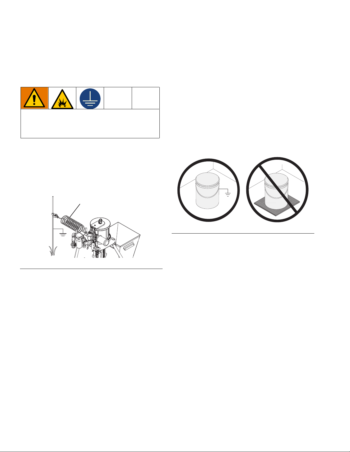
Grounding
The equipment must be grounded to reduce the risk
of static sparking. Static sparking can cause fumes to
ignite or explode. Grou nding pro vides an escape wire
for the electric current.
Tools Required
• Grounding wires and clamps for pails
• Two 5-gallon (19 L) metal pails
1. Connect the ground wire (L, 262908) to the ground
stud on the air motor.
2. Connect the other end of the ground wire to a true
earth ground.
3. Ground the object being sprayed, fluid supply
container, and all ot her eq uip ment in t he w ork area.
Follow your local code. Use only electrically
conductive air and fluid hoses.
4. Ground all pails. Use only metal pails, which are
conductive, placed on a metal sur f ace . Do not place
pail on a non-conductive surface, such as paper or
cardboard, which interrupts grounding continuity.
FIG. 10: Properly Grounded Pail
FIG. 9: Grounding Wire
10 3A5275B
Setup
R
ti21631a
B
A
ti21575a
Setup
Tools required:
• Two adjustable wrenches
• Non-sparking hammer or plastic mallet
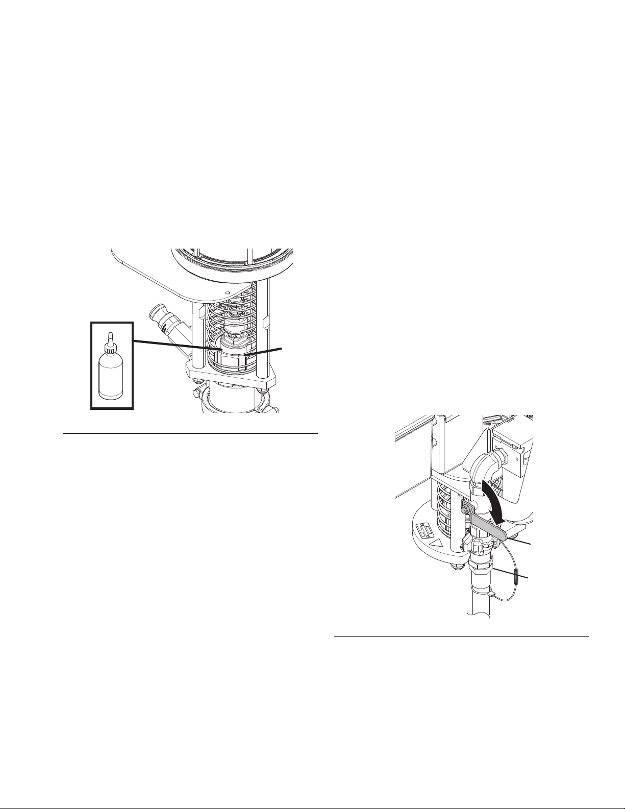
1. Ground sprayer. See Grounding, page 10.
2. Check Throat Seal Liquid (TSL) level in packing nut
(R). Fill 1/2 full with TSL.
9. Wrap blue velcro camlock retaining straps around
each camlock conn ection to secure.
NOTE: This includes the two camlocks between the
hopper and the pump lower, the camlock at the pump
outlet, the camlocks on the fluid hoses , and the ca mlock
on the applicator inlet. The retaining straps should be
tight and must not be able to slide off the camlocks.
10. Going from applicator back to the system, wrap a
zip tie around all hoses every few feet to secure
them together.
11. Connect air supply hose:
a. Close bleed type master air valve (B).
b. Expand end of whip check cable (Y) and slide it
over the end of your air hose.
c. Connect air supply hose to 3/4 npt(f) claw
fittings air inlet (A).
d. Install safety clips in claw fittings.
FIG. 11: Check Throat Seal Liquid Levels
3. Attach electrically conductive fluid hose to camlock
at pump outlet.
4. Attach large air line from hose bundle to main air
quick disconnect (N). See Component
Identification, page 8.
5. Attach large air line from hose bundle to motor pilo t
valve signal (X). Use wrench to secure air tube in
place. See Component Identification, page 8.
6. Attach applicator camlock reducer to applicator fluid
inlet.
7. Attach large air line from hose bundle to applicator
air inlet quick disconnect (W). See Component
Identification, page 8.
8. Attach small air tube from hose bundle to air motor
pilot ball valve (G) on applicator. Use wrench to
secure air tube place. See Component
Identification, page 8.
FIG. 12
12. Wet out the system with material flushin g agent
before using. See Wet Out the System, page 13.
3A5275B 11
 Loading...