

Page 1
Instructions - Parts
Communications
Gateway Module
3A5186B
Therm-O-Flow® Installation Kit
For use with Therm-O-Flow 20 and 200 systems to provide fieldbus communication
capabilities. For professional use only.
Kit No. 25C994
Important Safety Instructions
Read all warnings and instructions in this
manual and in all related manuals. Save all
instructions.
EN
Page 2

Related Manuals
Contents
Related Manuals . . . . . . . . . . . . . . . . . . . . . . . . . . . 2
Models . . . . . . . . . . . . . . . . . . . . . . . . . . . . . . . . . . . 2
Overview . . . . . . . . . . . . . . . . . . . . . . . . . . . . . . . . . . 2
Installation . . . . . . . . . . . . . . . . . . . . . . . . . . . . . . . . 3
Mounting the CGM . . . . . . . . . . . . . . . . . . . . . . . 3
Connecting the CAN Cables . . . . . . . . . . . . . . . . 3
Setup . . . . . . . . . . . . . . . . . . . . . . . . . . . . . . . . . . . . . 5
Gateway Screens . . . . . . . . . . . . . . . . . . . . . . . . 5
EtherNet/IP Fieldbus Screens . . . . . . . . . . . . . . . 5
DeviceNet Fieldbus Screen . . . . . . . . . . . . . . . . 5
PROFIBUS Fieldbus Screen . . . . . . . . . . . . . . . . 6
PROFINET Fieldbus Screens . . . . . . . . . . . . . . . 6
Maintenance . . . . . . . . . . . . . . . . . . . . . . . . . . . . . . . 8
Software Update Procedure . . . . . . . . . . . . . . . . 8
Available Internal Data . . . . . . . . . . . . . . . . . . . . . . 9
Automation Inputs (Signals from the Therm-O-Flow
to the PLC) . . . . . . . . . . . . . . . . . . . . . . . . . . 9
Automation Outputs (Signals from the PLC to the
Therm-O-Flow) . . . . . . . . . . . . . . . . . . . . . . 11
Parts . . . . . . . . . . . . . . . . . . . . . . . . . . . . . . . . . . . . 12
Kit No. 25C994 . . . . . . . . . . . . . . . . . . . . . . . . . 12
Appendix A - I/O Signal Descriptions . . . . . . . . . 13
Heat Zone States . . . . . . . . . . . . . . . . . . . . . . . 13
Status Indication Bit Tables . . . . . . . . . . . . . . . 13
System Control Bits . . . . . . . . . . . . . . . . . . . . . 14
Temperature Setpoint Zone Designation Table 16
Appendix B - Data Exchange Interface . . . . . . . . 17
Data Exchange Interface Pointer Designation Tabl
18
Appendix C - Error/Event Tables . . . . . . . . . . . . . 22
Related Manuals
Manual Description
Models
The following kit includes the Communications Gateway
Module (CGM) parts and software that are required for
Therm-O-Flow 20 or Therm-O-Flow 200 machines using
a CGM. This kit enables the Therm-O-Flow machines to
connect to a fieldbus device.
Part No. Description
25C994 Thermo-O-Flow CGM Installation Kit
Kit 25C994 is used with the following CGM models,
each of which includes all of the remaining parts necessary to install the CGM. See Communications Gateway
Module Instructions - Parts, manual 312864, for repair
parts for these assemblies.
Part No. Fieldbus
CGMEP0 EtherNet/IP
CGMDN0 DeviceNet
CGMPB0 PROFIBUS
CGMPN0 PROFINET
Overview
The Communications Gateway Module (CGM) provides
a control link between the Therm-O-Flow (TOF) system
and a selected fieldbus. The control link provides the
means for remote monitoring and control by external
automation systems.
The data available to the fieldbus from the CGM
depends on the amount of channels installed on the
Therm-O-Flow system. A data map is available on a
token provided in this kit.
See Available Internal Data on page 9 for a list of internal data from the Therm-O-Flow system that can be
viewed or modified by the fieldbus device.
312864 Communications Gateway Module
Instructions - Parts
334130 Therm-O-Flow 200 Instructions - Parts
334129 Therm-O-Flow 20 Instructions - Parts
406987 GCA CAN Cables, Reference
2 3A5186B
NOTE: The following system network configuration files
are available at www.graco.com.
• EDS file: DeviceNet or Ethernet/IP fieldbus networks
Page 3
Installation
Recommended
Location for
Mounting Holes
3.25 in.
(82.6 mm)
2.75 in.
(69.9 mm)
#10-32 UNF
(M5 x 0.8)
CAN Cable Connectors
D
A
C
B
Installation
NOTE: Turn off the main power switch on the
Therm-O-Flow before starting. See the Therm-O-Flow
manuals referenced in Related Manuals on page 2 for
information about turning off the power.
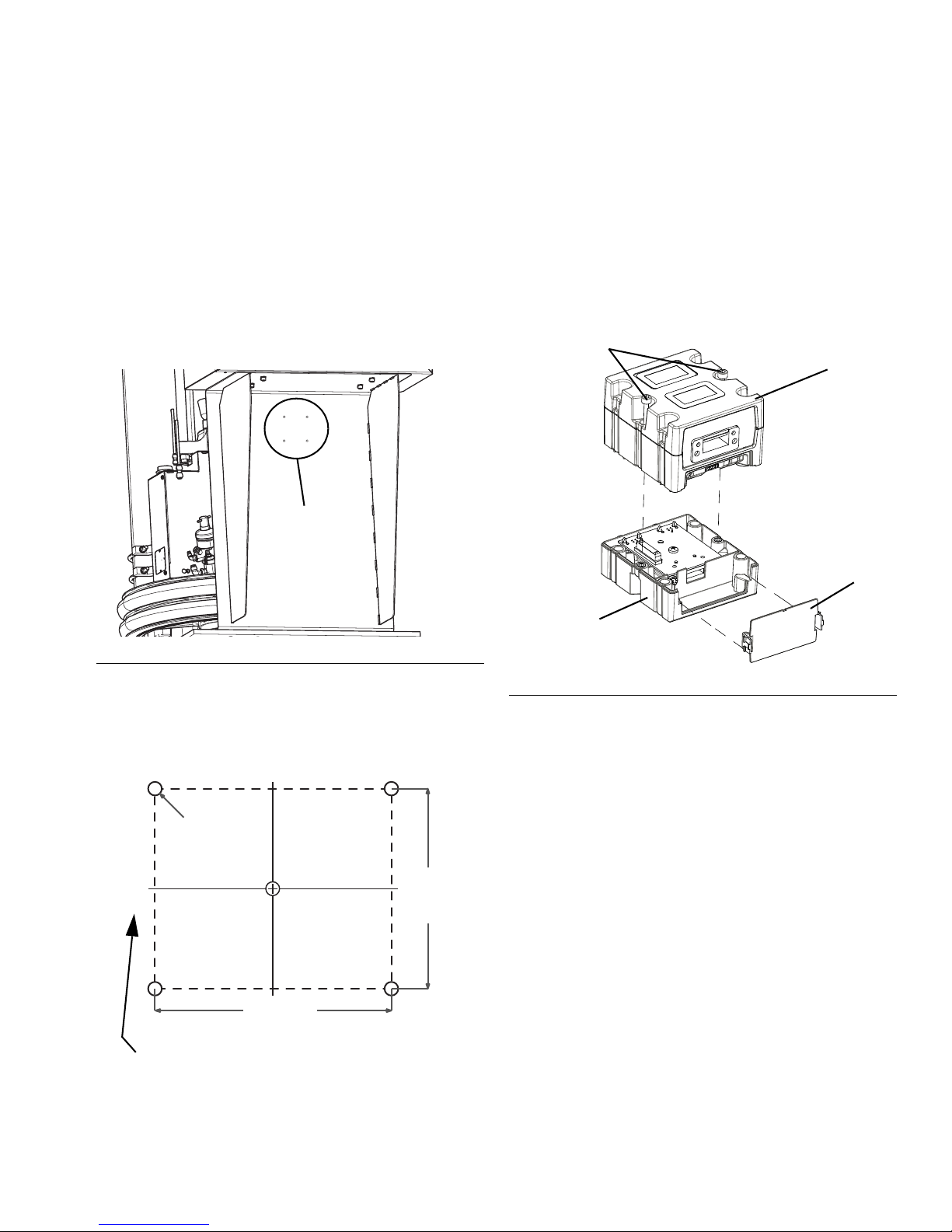
To install the CGM, you will need to drill mounting holes
on the Therm-O-Flow below the electrical control panel
in a location where the CAN cables can be connected to
the CGM. See Figure 1 for the recommended location.
Mounting the CGM
1. Drill the mounting holes.
2. Remove the access cover from the CGM (D).
Loosen the two screws (C) and remove the CGM
(A) from the base (B).
FIG. 1: Mounting Location
The center of the CGM should be 4 inches from the bottom of the electrical control panel and 8 inches from
each side. Refer to the following mounting dimensions
when drilling the holes for the CGM.
NOTE: Mount the CGM with the CAN cable connectors
on the left side to make it easier to connect the cables.
FIG. 2: Removing the CGM Access Cover
3. With the CAN connectors on the left side, mount the
base (B) in the mounting holes using the four
screws supplied in this kit. See Parts on page 12.
4. Mount the CGM (A) on the base (B) with the two
screws (C) that were removed in step 2.
5. Reattach the access cover (D).
Connecting the CAN Cables
1. Disconnect the ADM’s CAN cable from the ADM
and from the splitter on the back of the
Therm-O-Flow’s electrical control panel.
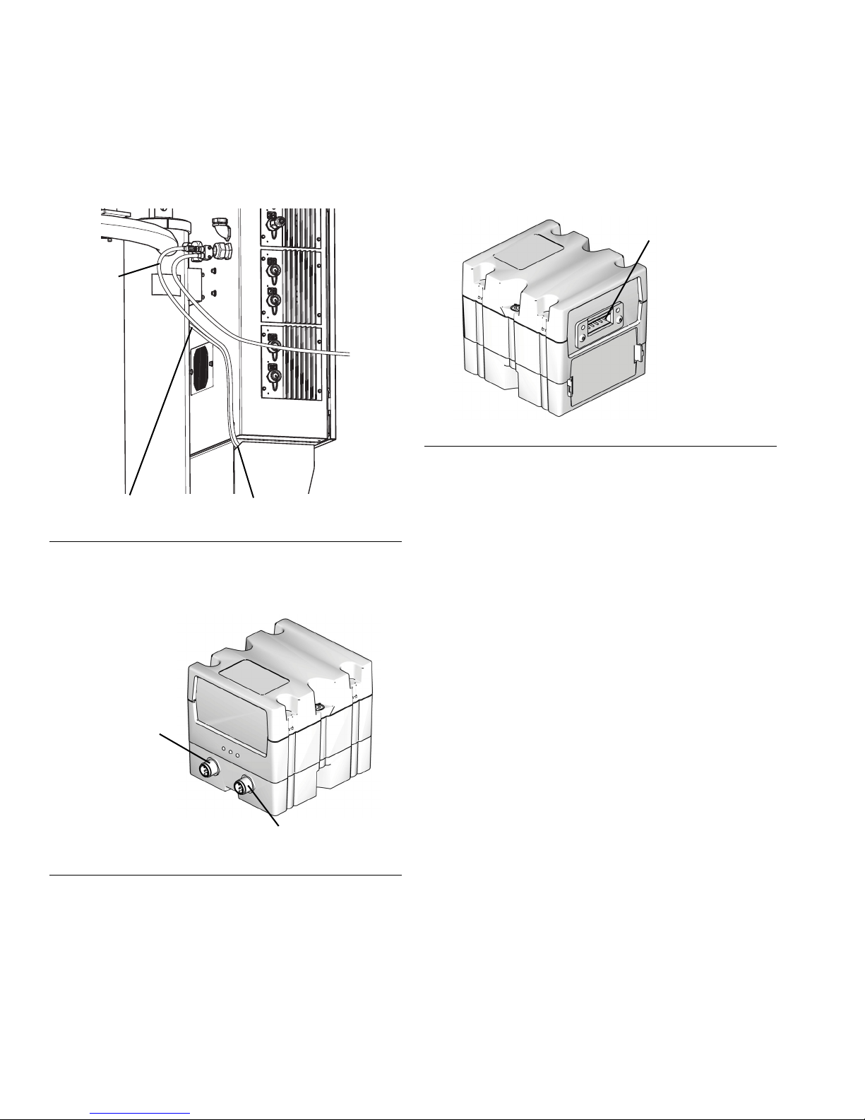
2. Connect one end of the 1.5 m (4.9 ft) CAN cable
included in this kit to the ADM. Run the cable down
and through the opening underneath the electrical
control box as shown in Figure 3.
3A5186B 3
Page 4
Installation
CAN Cable from ADM
CAN Cable
from Splitter
Opening Leading to CGM
CAN Connector 1
CAN Connector 2
Fieldbus Connection
3. Connect the CAN cable that you removed from the
ADM to the available splitter connection on the back
of the electrical control panel. Run that cable
through the same opening as the other CAN cable.
FIG. 3: CAN Cable Connection
4. Connect the two cables to the CGM connectors.
Either cable can be connected to either connector.
7. Connect the Ethernet, DeviceNet, or PROFIBUS
cable to the CGM as applicable. Connect the other
end of the cable to the fieldbus device.
FIG. 5: Connecting the Fieldbus
8. Perform the Install or Update Data Map procedure
in Communications Gateway Module Instructions -
Parts, manual 312864.
9. See the Available Internal Data on page 9 for
details on the fieldbus pinout setup.
10. Perform Setup on page 5 to configure the fieldbus.
FIG. 4: CGM Connectors
5. Attach the two ferrite suppressors included in the kit
to the ends of the two cables closest to the CGM.
6. Use the adhesive cable tie included in the kit to
attach the CAN cables to the back of the control
box.
4 3A5186B
Page 5

Setup
Setup
NOTICE
To prevent damage to soft key buttons on the ADM, do
not press the buttons with sharp objects such as pens,
plastic cards, or fingernails.
Gateway Screens
Use the Gateway screens on the ADM to configure the
fieldbus. These screens are shown only if a CGM is correctly installed in your system. See Installation on page
3.
1. With the system on and enabled, press on the
ADM to access the Setup screens.
2. Use the ADM’s arrow keys to navigate to the main
Gateway screen.
EtherNet/IP Fieldbus Screens
Screen 2
Use the down arrow key on the ADM to navigate to
screen 2. This screen displays the hardware revision,
system serial number, and data map identification information.
DeviceNet Fieldbus Screen
NOTE: These screens are shown only if you have an
EtherNet/IP fieldbus CGM installed.
Screen 1
Press the key to access this screen. Use the arrow
keys to navigate to each field and the keypad to set the
IP address, DHCP settings, subnet mask, gateway, and
DNS information.
NOTE: This screen is shown only if you have a DeviceNet fieldbus CGM installed.
Press the key to access this screen. You can set
the device address and baud rate. You can also view
the hardware revision, system serial number, and data
map identification information.
3A5186B 5
Page 6
Setup
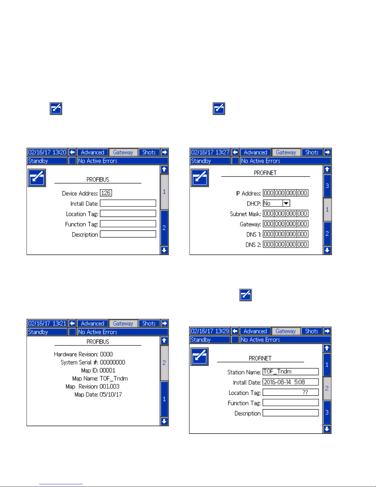
PROFIBUS Fieldbus Screen
NOTE: These screens are shown only if you have a
PROFIBUS fieldbus CGM installed.
Screen 1
Press the key to access this screen. Use the arrow
keys to navigate to each field and the keypad to set the
device address, install date, location tag, function tag,
and description.
PROFINET Fieldbus Screens
NOTE: These screens are shown only if you have a
PROFINET fieldbus CGM installed.
Screen 1
Press the key to access this screen. Use the arrow
keys to navigate to each field and the keypad to set the
IP address, DHCP settings, subnet mask, gateway, and
DNS information.
Screen 2
Use the down arrow key on the ADM to navigate to
screen 2. This screen displays the hardware revision,
system serial number, and data map identification information.
Screen 2
Use the down arrow key on the ADM to navigate to
screen 2. Press the key to access this screen. You
can set the station name, install date, location tag, function tag, and description.
6 3A5186B
Page 7

Screen 3
Use the down arrow key on the ADM to navigate to
screen 3. This screen displays the hardware revision,
system serial number, and data map identification information.
Setup
3A5186B 7
Page 8

Maintenance
Maintenance
Software Update Procedure
When software is updated on the ADM, the software is
then automatically updated on the CGM and all other
connected Graco Control Architecture components.
1. At the ADM, turn the power switch to Off.
2. Remove the ADM from the bracket.
3. Use a hex key to remove the token access panel.
6. The Graco Splash screen is displayed until communication with other modules is established.
7. Wait for the update to complete. An approximate
time to completion displays below the progress bar.
8. When the update is completed successfully, press
the key.
FIG. 6: Token Location
4. Insert and press the software upgrade token firmly
into the slot.
5. Turn the power switch to On.
NOTICE
A status is shown while software is updating to indicate progress. To prevent corrupting the software
load, do not remove the token until the status screen
disappears.
9. Remove the token and replace the token access
panel.
NOTE: The software version history for each system
can be viewed in the technical support section at
www.graco.com.
8 3A5186B
Page 9

Available Internal Data
Available Internal Data
See Appendix A - I/O Signal Descriptions on page 13 for additional details regarding each input/output. Unless
stated otherwise:
• Values are subject to the same maximum and minimum restrictions of the ADM.
• Some of the temperature data may have slight rounding errors compared to temperatures displayed on the ADM.
• On some controlling devices, the byte order may need to be reversed (byte order within instance, least significant
-> most significant.
Automation Inputs (Signals from the Therm-O-Flow to the PLC)
Instance
Number
1 0 -1 Pump Actual Temperature, Primary °C/°F
2 2 - 3 Platen Actual Temperature, Primary °C/°F
3 4 - 5 Zone #1 Actual Temperature, Primary °C/°F
4 6 - 7 Zone #2 Actual Temperature, Primary °C/°F
5 8 - 9 Zone #3 Actual Temperature, Primary °C/°F
6 10 - 11 Zone #4 Actual Temperature, Primary °C/°F
7 12 - 13 Zone #5 Actual Temperature, Primary °C/°F
8 14 - 15 Zone #6 Actual Temperature, Primary °C/°F
9 16 - 17 Zone #7 Actual Temperature, Primary °C/°F
10 18 - 19 Zone #8 Actual Temperature, Primary °C/°F
11 20 - 21 Zone #9 Actual Temperature, Primary °C/°F
12 22 - 23 Zone #10 Actual Temperature, Primary °C/°F
13 24 - 25 Zone #11 Actual Temperature, Primary °C/°F
14 26 - 27 Zone #12 Actual Temperature, Primary °C/°F
15 28 - 29 Pump Setpoint Temperature Indication, Primary/Secondary °C/°F
16 30 - 31 Platen Setpoint Temperature Indication, Primary/Secondary °C/°F
17 32 - 33 Zone #1 Setpoint Temperature Indication, Primary/Secondary °C/°F
18 34 - 35 Zone #2 Setpoint Temperature Indication, Primary/Secondary °C/°F
19 36 - 37 Zone #3 Setpoint Temperature Indication, Primary/Secondary °C/°F
20 38 - 39 Zone #4 Setpoint Temperature Indication, Primary/Secondary °C/°F
21 40 - 41 Zone #5 Setpoint Temperature Indication, Primary/Secondary °C/°F
22 42 - 43 Zone #6 Setpoint Temperature Indication, Primary/Secondary °C/°F
23 44 - 45 Zone #7 Setpoint Temperature Indication, Primary/Secondary °C/°F
24 46 - 47 Zone #8 Setpoint Temperature Indication, Primary/Secondary °C/°F
25 48 - 49 Zone #9 Setpoint Temperature Indication, Primary/Secondary °C/°F
26 50 - 51 Zone #10 Setpoint Temperature Indication, Primary/Secondary °C/°F
27 52 - 53 Zone #11 Setpoint Temperature Indication, Primary/Secondary °C/°F
28 54 - 55 Zone #12 Setpoint Temperature Indication, Primary/Secondary °C/°F
29 56 - 57 Pump, Platen, Zones 1 – 3 States, Primary
30 58 - 59 Zones 4 – 8 States, Primary
31 60 - 61 Zones 9 – 12 States, Primary
32* 62 - 63 Pump Setback Setpoint Temperature Indication, Primary/Secondary °C/°F
33* 64 - 65 Platen Setback Setpoint Temperature Indication, Primary/Secondary °C/°F
34* 66 - 67 Zone #1 Setback Setpoint Temperature Indication, Primary/Secondary °C/°F
35* 68 - 69 Zone #2 Setback Setpoint Temperature Indication, Primary/Secondary °C/°F
36* 70 - 71 Zone #3 Setback Setpoint Temperature Indication, Primary/Secondary °C/°F
37* 72 - 73 Zone #4 Setback Setpoint Temperature Indication, Primary/Secondary °C/°F
Input Byte
Index(es)
Description Units
3A5186B 9
Page 10

Available Internal Data
Instance
Number
Input Byte
Index(es)
Description Units
38* 74 - 75 Zone #5 Setback Setpoint Temperature Indication, Primary/Secondary °C/°F
39* 76 - 77 Zone #6 Setback Setpoint Temperature Indication, Primary/Secondary °C/°F
40* 78 - 79 Zone #7 Setback Setpoint Temperature Indication, Primary/Secondary °C/°F
41* 80 - 81 Zone #8 Setback Setpoint Temperature Indication, Primary/Secondary °C/°F
42* 82 - 83 Zone #9 Setback Setpoint Temperature Indication, Primary/Secondary °C/°F
43* 84 - 85 Zone #10 Setback Setpoint Temperature Indication, Primary/Secondary °C/°F
44* 86 - 87 Zone #11 Setback Setpoint Temperature Indication, Primary/Secondary °C/°F
45* 88 - 89 Zone #12 Setback Setpoint Temperature Indication, Primary/Secondary °C/°F
46** 90 - 91 Pump Actual Temperature, Secondary °C/°F
47** 92 - 93 Platen Actual Temperature, Secondary °C/°F
48** 94 - 95 Zone #1 Actual Temperature, Secondary °C/°F
49** 96 - 97 Zone #2 Actual Temperature, Secondary °C/°F
50** 98 - 99 Zone #3 Actual Temperature, Secondary °C/°F
51** 100 - 101 Zone #4 Actual Temperature, Secondary °C/°F
52** 102 - 103 Zone #5 Actual Temperature, Secondary °C/°F
53** 104 - 105 Zone #6 Actual Temperature, Secondary °C/°F
54** 106 - 107 Zone #7 Actual Temperature, Secondary °C/°F
55** 108 - 109 Zone #8 Actual Temperature, Secondary °C/°F
56** 110 - 111 Zone #9 Actual Temperature, Secondary °C/°F
57** 112 - 113 Zone #10 Actual Temperature, Secondary °C/°F
58** 114 - 115 Zone #11 Actual Temperature, Secondary °C/°F
59** 116 - 117 Zone #12 Actual Temperature, Secondary °C/°F
60** 118 - 119 Pump, Platen, Zones 1 – 3 States, Secondary
61** 120 - 121 Zones 4 – 8 States, Secondary
62** 122 - 123 Zones 9 – 12 States, Secondary
63** 124 - 127 Error / Event Code(s) Present †
64** 128 - 131 Error / Event Code(s) Needing Acknowledged †
65** 132 - 133 Status Word 1 Indication Bits
66** 134 - 135 Status Word 2 Indication Bits
67** 136 - 137 Data Exchange Interface Pointer Last Serviced
68** 138 - 141 Data Exchange Interface Input Value
69** 142 System Mode/State, Primary ‡
70** 143 System Mode/State, Secondary ‡
* Data instances (setback mode setpoint temperatures) are NOT provided for the PROFIBUS and PROFINET versions of the map since the
field protocols do not support that large of a map size. For PROFIBUS or PROFINET, you should use the data exchange interface to obtain
setback setpoint information.
** For the PROFIBUS or PROFINET versions of the map, 14 should be subtracted from the instance number and 28 should be subtracted for the
input byte count so that the PROFIBUS and PROFINET versions have 56 input instances containing 116 input bytes total.
Zone states are packed in groups of three bits, where each zone state equates to the following. Each zone is packed from bit 0, bit 3, bit 6, bit
9, and bit 12 corresponding to the order presented in the description. 000 - zone is not installed, 001 - zone is off, 010 - zone is in warm up
state, 011 - zone is in heat soak state, 100 - zone at temperature, 101 - zone in setback mode.
Temperature units match units of the ADM. Values are in tenths of a degree (for example, a value of 4005 corresponds to 400.5 °F). Setpoint
temperatures are either for the primary or secondary unit, depending on the system selected by the PLC in the System Control Word.
† See Appendix C - Error/Event Tables on page 22.
See the Status Indication Bit Tables on page 13.
See Appendix B - Data Exchange Interface on page 17.
‡ System Mode/State: 0 = System Off, 1 = Inactive, 2 = Warm Up, 3 = Heat Soak, 4 = Ready (at temperature, heat soak done, pump off), 5 =
Active (at ready and pump ON), 6 = Setback Mode.
10 3A5186B
Page 11

Available Internal Data
Automation Outputs (Signals from the PLC to the Therm-O-Flow)
Instance
Number
Output
Bytes
Description Units
1 0 System Activate/Stop *
2 1 Setpoint Zone Designation **
3 2 - 3 Setpoint Temperature for Selected Zone °C/°F**
4 4 - 5 System Control Bits
5 6 - 9 Error/Event Number Acknowledged †
6 10 - 11 Data Exchange Interface Pointer Output Designation
7 12 - 15 Data Exchange Interface Output Value
* Set this byte to one of the following: 0 = Do Nothing, 1 = Turns ON the System (same as pressing the key), 2-255 = Shuts Down the
System (same as pressing the key).
** Used to set the temperature setpoints to tenths of a degree (for example, 3005 = 300.5) in the selected units of measurement (°C or °F). See
the Temperature Setpoint Zone Designation Table on page 16.
See System Control Bits on page 14.
† See the Appendix C - Error/Event Tables on page 22
See Appendix B - Data Exchange Interface on page 17.
3A5186B 11
Page 12

Parts
6
7
15
20
13
CGM shown for mounting
purposes only.
Not included in kit.
Parts
Kit No. 25C994
FIG. 7: Kit 25C994 Parts
Ref Part Description Quantity
6 96/0650/99 SCREW, tapping, phillips pan hd 4
7 17T051 TOKEN, gca, map, tof cgm 1
917T053 SOFTWARE, gateway, tof, gsd 1
10 17T054 SOFTWARE, gateway, tof, eds 1
11 17T055 SOFTWARE, gateway, tof, gsdml 1
13 121901 SUPPRESSOR, box snap, ferrite 2
15 16H821 TOKEN, gca, upgrade, adm32 1
19 17T056 KIT, sample program 1
20 121002 CABLE, can, female/female 1.5 m 1
21 84/0805/89 CABLE, TIE MOUNT, 1 x 1 sq w/adhesive 1
Not shown.
NOTE: The CGM is not included in the kit. See Models on page 2 for available CGM modules.
12 3A5186B
Page 13

Appendix A - I/O Signal Descriptions
Appendix A - I/O Signal Descriptions
This section provides details about the CGM automation input and output signals.
Heat Zone States
The signal is 0 on power up. The following values of this signal correspond to the various heat zone states. Each
zone is bit packed into 3 bits for each zone designation in input instances 29-31 and 60-62 of the map.
Number Binary # Heat Zone State
0 000 Zone Not Installed
1 001 OFF
2 010 Warm Up
3 011 Heat Soak State
4 100 At Temperature
5 101 Setback Mode
Status Indication Bit Tables
The following tables reflect bit-packed data, which corresponds to the status words located at input instances 65 and
66.
Status Word 1 Indication Bits
Bit
Number
0 0x0001 0000 0000 0000 0001 System is ON
1 0x0002 0000 0000 0000 0010 Active System is Secondary (B) System
2 0x0004 0000 0000 0000 0100 Heat is Turned ON for Primary (A) System
3 0x0008 0000 0000 0000 1000 Heat is Turned ON for Secondary (B) System
4 0x0010 0000 0000 0001 0000 Setpoint Indications are for Secondary (B) System
5 0x0020 0000 0000 0010 0000 Setback Setpoint Indications are for Secondary (B) System
6 0x0040 0000 0000 0100 0000 Material Tracking is ON or Active
7 0x0080 0000 0000 1000 0000 Pump Priming is Active for Primary (A) System
8 0x0100 0000 0001 0000 0000 Pump Priming is Active for Secondary (B) System
9 0x0200 0000 0010 0000 0000 Pump is ON for Primary (A) System
10 0x0400 0000 0100 0000 0000 Pump is ON for Secondary (B) System
11 0x0800 0000 1000 0000 0000 Setback Mode is Active for Primary (A) System
12 0x1000 0001 0000 0000 0000 Setback Mode is Active for Secondary (B) System
13 0x2000 0010 0000 0000 0000 Data Exchange Interface is Active or in Transition
14-15 ------ ------ Reserved for Future Use
Hex
Equivalent
Binary Number Description
3A5186B 13
Page 14

Appendix A - I/O Signal Descriptions
Status Word 2 Indication Bits
Bit
Number
Hex
Equivalent
Binary Number Description
0 0x0001 0000 0000 0000 0001 Heat Soak Timer Active for Primary (A) System
1 0x0002 0000 0000 0000 0010 Heat Soak Timer Active for Secondary (B) System
2 0x0004 0000 0000 0000 0100 Turn ON Primary System (A), Heat Command Active
3 0x0008 0000 0000 0000 1000 Turn ON Secondary System (B), Heat Command Active
4 0x0010 0000 0000 0001 0000 Prime/Pump on A Command Active
5 0x0020 0000 0000 0010 0000 Prime/Pump on B Command Active
6 0x0040 0000 0000 0100 0000 Setback A Command Active
7 0x0080 0000 0000 1000 0000 Setback B Command Active
8 0x0100 0000 0001 0000 0000 Cross Over Command Active
9 0x0200 0000 0010 0000 0000 PLC Control Active Indication
10 0x0400 0000 0100 0000 0000
Heart Beat Indication for PLC from TOF (
Control Bits
)
See Note 7 in System
11 0x0800 0000 1000 0000 0000 Error/Event Reported is an Alarm
12-15 ------ ------ Reserved for Future Use
System Control Bits
The following table reflects the bit variables in output instance 4, which can be set or cleared to control the following
conditions.
Bit
Number
Hex
Equivalent
Binary Number Description Notes
0 0x0001 0000 0000 0000 0001 Turn ON Heat Command for System A Command 1
1 0x0002 0000 0000 0000 0010 Turn ON Head Command for System B Command 1
2 0x0004 0000 0000 0000 0100 Turn ON/Prime Pumps for System A Command 2
3 0x0008 0000 0000 0000 1000 Turn ON/Prime Pumps for System B Command 2
4 0x0010 0000 0000 0001 0000 Setback Command System A 3
5 0x0020 0000 0000 0010 0000 Setback Command System B 3
6 0x0040 0000 0000 0100 0000 Cross Over Command 4
7 0x0080 0000 0000 1000 0000 Pause Material Tracking/Counters Command 5
8 0x0100 0000 0001 0000 0000 Continue Material Tracking Command 5
9 0x0200 0000 0010 0000 0000 Command Setpoint Indications on Map for System B 6
10 0x0400 0000 0100 0000 0000 Command Setback Setpoint Indications for System B 6
11 0x0800 0000 1000 0000 0000 Heart Beat Output to TOF 7
12 0x1000 0001 0000 0000 0000 PLC Control Command 8
13-15 ------ ------ Reserved for Future Use
1 Same as pressing on the main Run screen.
2 Same as pressing on the main Run screen.
3 Same as pressing on the main Run screen.
4 Same as pressing on the main Run screen.
5 Same as pressing or on the main Run screen.
14 3A5186B
Page 15

Appendix A - I/O Signal Descriptions
6 After changing the state of the command XX setpoint indications on the map for the Secondary B system bit, the controlling PLC logic should
monitor the corresponding status indication bit and verify it corresponds to the command bit before monitoring the corresponding setpoint indication from the Therm-O-Flow.
7 The PLC or controlling logic needs to generate a dynamic signal at approximately a 0.333 Hz (1.5 seconds high, 1.5 seconds low) oscillation
rate. The signal is present to enable detection of a communication failure between the Therm-O-Flow system and the controlling logic. The
TOF system also generates the same rate dynamic signal indication (heart beat indication for PLC from TOF) signal for controlling logic to the
monitor.
8 The PLC Control Command bit needs to be set, and the controlling logic needs to generate a valid heart beat output (described in note 7) to
the Therm-O-Flo system before the TOF will grant the PLC requests or commands. If the heart beat output to TOF becomes a static signal
(always low or high) after an extended period of time while the TOF is in PLC control, the TOF reverts to a safe state, and generates a corre-
sponding alarm. This situation would be similar to an operator pressing the key
3A5186B 15
Page 16

Appendix A - I/O Signal Descriptions
Temperature Setpoint Zone Designation Table
The following table shows the setpoint designations in
output instance 2 used to command the Therm-O-Flow
temperature zones to the corresponding setpoint. Prior
to writing to instance 2, the PLC needs to write the
desired temperature setpoint (in tenths of a degree for
the selected temperature unit of measure) to output
instance 3 for the selected zone. After the zone designation has been written, the PLC can monitor the setpoint change by monitoring the correct setpoint
indications: input instances 15-28 or 32-45.
Zone
Number
Designation
0 No Zone Selected
1 Pump Setpoint Temperature, Primary
2 Platen Setpoint Temperature, Primary
3 Zone 1 Setpoint Temperature, Primary
4 Zone 2 Setpoint Temperature, Primary
5 Zone 3 Setpoint Temperature, Primary
6 Zone 4 Setpoint Temperature, Primary
7 Zone 5 Setpoint Temperature, Primary
8 Zone 6 Setpoint Temperature, Primary
9 Zone 7 Setpoint Temperature, Primary
10 Zone 8 Setpoint Temperature, Primary
11 Zone 9 Setpoint Temperature, Primary
12 Zone 10 Setpoint Temperature, Primary
13 Zone 11 Setpoint Temperature, Primary
14 Zone 12 Setpoint Temperature, Primary
15 Pump Setpoint Temperature, Secondary
16 Platen Setpoint Temperature, Secondary
17 Zone 1 Setpoint Temperature, Secondary
18 Zone 2 Setpoint Temperature, Secondary
19 Zone 3 Setpoint Temperature, Secondary
20 Zone 4 Setpoint Temperature, Secondary
21 Zone 5 Setpoint Temperature, Secondary
22 Zone 6 Setpoint Temperature, Secondary
23 Zone 7 Setpoint Temperature, Secondary
24 Zone 8 Setpoint Temperature, Secondary
25 Zone 9 Setpoint Temperature, Secondary
26 Zone 10 Setpoint Temperature, Secondary
27 Zone 11 Setpoint Temperature, Secondary
28 Zone 12 Setpoint Temperature, Secondary
61 Pump Setback Setpoint Temperature, Primary
62 Platen Setback Setpoint Temperature, Primary
Zone 1 Setback Setpoint Temperature, Pri-
63
mary
Zone 2 Setback Setpoint Temperature, Pri-
64
mary
Description
Zone 3 Setback Setpoint Temperature, Pri-
65
mary
Zone 4 Setback Setpoint Temperature, Pri-
66
mary
Zone 5 Setback Setpoint Temperature, Pri-
67
mary
Zone 6 Setback Setpoint Temperature, Pri-
68
mary
Zone 7 Setback Setpoint Temperature, Pri-
69
mary
Zone 8 Setback Setpoint Temperature, Pri-
70
mary
Zone 9 Setback Setpoint Temperature, Pri-
71
mary
Zone 10 Setback Setpoint Temperature, Pri-
72
mary
Zone 11 Setback Setpoint Temperature, Pri-
73
mary
Zone 12 Setback Setpoint Temperature, Pri-
74
mary
Pump Setback Setpoint Temperature, Sec-
75
ondary
Platen Setback Setpoint Temperature, Sec-
76
ondary
Zone 1 Setback Setpoint Temperature, Sec-
77
ondary
Zone 2 Setback Setpoint Temperature, Sec-
78
ondary
Zone 3 Setback Setpoint Temperature, Sec-
79
ondary
Zone 4 Setback Setpoint Temperature, Sec-
80
ondary
Zone 5 Setback Setpoint Temperature, Sec-
81
ondary
Zone 6 Setback Setpoint Temperature, Sec-
82
ondary
Zone 7 Setback Setpoint Temperature, Sec-
83
ondary
Zone 8 Setback Setpoint Temperature, Sec-
84
ondary
Zone 9 Setback Setpoint Temperature, Sec-
85
ondary
Zone 10 Setback Setpoint Temperature, Sec-
86
ondary
Zone 11 Setback Setpoint Temperature, Sec-
87
ondary
Zone 12 Setback Setpoint Temperature, Sec-
88
ondary
16 3A5186B
Page 17

Appendix B - Data Exchange Interface
Appendix B - Data Exchange Interface
The Data Exchange Interface is a bi-directional interface
that enables both transmitting and receiving data
between the Therm-O-Flow system and the controlling
logic (PLC). The interface allows a large amount of data
to exchange between the systems while only occupying
a very small data map to support the exchange. The
interface also allows for future expansion of data without
changing the map structure.
To get or receive data from the supply system, the controlling PLC needs to:
1. Write to the Data Exchange Interface Pointer Output
Designation location on the map (output instance 6)
a value corresponding to the data the PLC wants to
receive.
2. Wait for the Therm-O-Flow to provide the same
Pointer Designation number written in the previous
step at input instance 67 (Data Exchange Interface
Pointer Last Serviced).
3. Read the requested data at input instance 68, Data
Exchange Interface Input Value.
After valid data is present at the input instances, the
Therm-O-Flow system clears the bit. While the bit is set,
the controlling PLC should ignore the interface inputs
until the bit is cleared. After the Therm-O-Flow system
services the request, the designation pointer input
matches the designation pointer output. If the scan rate
of the controlling PLC or control logic is slow enough,
monitoring of the status bit may not be necessary.
NOTE: When changes are made over the Data
Exchange Interface, the Therm-O-Flow system display
screen may not update immediately. It may be necessary to navigate away from the screen, then back to it.
To write or transmit data to the supply system, the controlling PLC needs to:
1. Write the data for the Therm-O-Flow system to the
Data Exchange Interface Output Value location, output instance 7.
2. Write to the Data Exchange Interface Pointer Output
Designation location on the map (output instance 6)
a value corresponding to the data the PLC is going
to transmit to the supply system.
3. The Therm-O-Flow system echoes back to the PLC
the Pointer Designation and the Data Interface
Value after the Therm-O-Flow system processes
the data transmit request to input instances 67 and
68 respectively.
When the controlling logic is exchanging data over this
interface, the Therm-O-Flow system sets the Data
Exchange Interface Active or in Transition status bit
while it processes the request and writes to the Data
Exchange Interface input locations (input instances 67
and 68).
3A5186B 17
Page 18

Appendix B - Data Exchange Interface
Data Exchange Interface Pointer Designation Tabl
Description Comments
Pointer
Designation
0 Interface Not Active
1 Set Temperature Units
2 Read Temperature Units Write
3 Set Mass Units
4 Read Mass Units Read
5 Set Specific Gravity
6 Read Specific Gravity Read
7 Set High Temp. Alarm Offset
8 Get High Temp. Alarm Offset Read
9 Set High Temp. Deviation Offset Write
10 Get High Temp. Deviation Offset Read
11 Set Low Temp. Alarm Offset Write
Value - Setting
0 - °F
1 - °C
Value - Setting (0 - g, 1 - kg, 2 - lb)
Specific gravity in thousandths (for instance a SG setting of
1.055 = 1055).
In whole selected C or F units of measure.
Read/
Write
Read
Write
Write
Write
12 Get Low Temp. Alarm Offset Read
13 Set Low Temp. Deviation Offset Write
14 Get Low Temp. Deviation Offset Read
15 Set Prime Pump Duration
16 Get Prime Pump Duration Read
17 Read System Version
18 Read System Date
19 Read System Time
20 Read ADM Version
21 - 90 Reserved for Future Use
Prime pump duration setting in second increments
A 32-bit string in the format of 0xXXCCBBAA.
0xCC…Build Version
0xBB…Minor Version
0xAA…Major Version
A 32-bit string in the format of 0xXXDDCCBB.
0xDD…Year (0x0D corresponds to 2013)
0xCC…Month (0x0A corresponds to October)
0xBB…Day
A 32-bit string in the format of 0xDDHHMMSS.
0xHH…Hours
0xMM…Minutes
0xSS…Seconds
0xDD...Day of week (0x01 corresponds to Monday)
A 32-bit string in the format of 0xXXMMNNBB
0xMM...Major #
0xNN...Minor #
0xBB...Build #
Write
Read
Read
Read
18 3A5186B
Page 19

Appendix B - Data Exchange Interface
Description Comments
Read/
Write
Pointer
Designation
Read Pump A Resettable Mate-
91
rial counter
Read Pump B Resettable Mate-
92
rial counter
Reset Pump A Resettable mate-
93
rial counter
Reset Pump B Resettable mate-
94
rial counter
Read Pump A Resettable Cycle
95
counter
Read Pump B Resettable Cycle
96
counter
Reset Pump A Resettable Cycle
97
counter
Reset Pump B Resettable Cycle
98
counter
99-100
Reserved for Future Use
101 Get Heat Soak Timer A
102
Get Heat Soak Timer B Read
103 -
Reserved for Future Use
110
In selected mass units, times 10. So, for instance, if in Kg mode,
101 = 10.1 Kg.
No Data required for Data Exchange Interface Output Value
location (Same as pressing on the corresponding setup or
run screen).
In whole pump cycle units of measure.
No Data required for Data Exchange Interface Output Value
location (Same as pressing on the corresponding setup or
run screen).
Get Primary or Secondary Heat Soak timer Remaining Count in
Seconds (= 0 if not active)
Write
Write
Write
Write
Read
111 Get CV Percent (5051 = 50.51%) Get Control Variable for Pump, Primary Heat Zone Read
112
Get CV Percent (5051 = 50.51%) Get Control Variable for Platen, Primary Heat Zone Read
113
Get CV Percent (5051 = 50.51%) Get Control Variable for Heat Zone 1, Primary Read
114
Get CV Percent (5051 = 50.51%) Get Control Variable for Heat Zone 2, Primary Read
115
Get CV Percent (5051 = 50.51%) Get Control Variable for Heat Zone 3, Primary Read
116
Get CV Percent (5051 = 50.51%) Get Control Variable for Heat Zone 4, Primary Read
117
Get CV Percent (5051 = 50.51%) Get Control Variable for Heat Zone 5, Primary Read
118
Get CV Percent (5051 = 50.51%) Get Control Variable for Heat Zone 6, Primary Read
119
Get CV Percent (5051 = 50.51%) Get Control Variable for Heat Zone 7, Primary Read
120
Get CV Percent (5051 = 50.51%) Get Control Variable for Heat Zone 8, Primary Read
121
Get CV Percent (5051 = 50.51%) Get Control Variable for Heat Zone 9, Primary Read
122
Get CV Percent (5051 = 50.51%) Get Control Variable for Heat Zone 10, Primary Read
123
Get CV Percent (5051 = 50.51%) Get Control Variable for Heat Zone 11, Primary Read
124
Get CV Percent (5051 = 50.51%) Get Control Variable for Heat Zone 12, Primary Read
read
read
read
read
3A5186B 19
Page 20

Appendix B - Data Exchange Interface
Pointer
Designation
125
126
127
128
129
130
131
132
133
134
135
136
137
138
139 -
150
151
152
153
154
155
156
157
158
159
160
161
162
163
164
Description Comments
Read/
Write
Get CV Percent (5051 = 50.51%) Get Control Variable for Pump, Secondary Heat Zone Read
Get CV Percent (5051 = 50.51%) Get Control Variable for Platen, Secondary Heat Zone Read
Get CV Percent (5051 = 50.51%) Get Control Variable for Heat Zone 1, Secondary Read
Get CV Percent (5051 = 50.51%) Get Control Variable for Heat Zone 2, Secondary Read
Get CV Percent (5051 = 50.51%) Get Control Variable for Heat Zone 3, Secondary Read
Get CV Percent (5051 = 50.51%) Get Control Variable for Heat Zone 4, Secondary Read
Get CV Percent (5051 = 50.51%) Get Control Variable for Heat Zone 5, Secondary Read
Get CV Percent (5051 = 50.51%) Get Control Variable for Heat Zone 6, Secondary Read
Get CV Percent (5051 = 50.51%) Get Control Variable for Heat Zone 7, Secondary Read
Get CV Percent (5051 = 50.51%) Get Control Variable for Heat Zone 8, Secondary Read
Get CV Percent (5051 = 50.51%) Get Control Variable for Heat Zone 9, Secondary Read
Get CV Percent (5051 = 50.51%) Get Control Variable for Heat Zone 10, Secondary Read
Get CV Percent (5051 = 50.51%) Get Control Variable for Heat Zone 11, Secondary Read
Get CV Percent (5051 = 50.51%) Get Control Variable for Heat Zone 12, Secondary Read
Reserved for Future Use
Get Pump A Setback Setpoint
Temperature
Get Platen A Setback Setpoint
Temperature
Get Zone 1, A Setback Setpoint
Temperature
Get Zone 2, A Setback Setpoint
Temperature
Get Zone 3, A Setback Setpoint
Temperature
Get Zone 4, A Setback Setpoint
Temperature
Get Zone 5, A Setback Setpoint
Temperature
Get Zone 6, A Setback Setpoint
Temperature
Get Zone 7, A Setback Setpoint
Temperature
Get Zone 8, A Setback Setpoint
Temperature
Get Zone 9, A Setback Setpoint
Temperature
Get Zone 10, A Setback Setpoint
Temperature
Get Zone 11, A Setback Setpoint
Temperature
Get Zone 12, A Setback Setpoint
Temperature
Provides the selected Primary System Zone Setback Mode setpoint temperature setting to the interface. Temperature Units
match units of the ADM. Values are in tenths of a degree (for
example, a value of 2505 corresponds to 250.5°F). These
pointer designations are typically used for PROFIBUS and
PROFINET applications.
Read
Read
Read
Read
Read
Read
Read
Read
Read
Read
Read
Read
Read
Read
20 3A5186B
Page 21

Appendix B - Data Exchange Interface
Pointer
Designation
165
166
167
168
169
170
171
172
173
174
175
176
177
178
179 ~65k
Description Comments
Get Pump B Setback Setpoint
Temperature
Get Platen B Setback Setpoint
Temperature
Get Zone 1, B Sec. Setback Setpoint Temperature
Get Zone 2, B Setback Setpoint
Temperature
Get Zone 3, B Setback Setpoint
Temperature
Get Zone 4, B Setback Setpoint
Temperature
Get Zone 5, B Setback Setpoint
Temperature
Get Zone 6, B Setback Setpoint
Temperature
Get Zone 7, B Setback Setpoint
Temperature
Get Zone 8, B Setback Setpoint
Temperature
Get Zone 9, B Setback Setpoint
Temperature
Get Zone 10, B Setback Setpoint Temperature
Get Zone 11, B Setback Setpoint Temperature
Get Zone 12, B Setback Setpoint Temperature
Reserved for Future Use
Provides the selected Secondary System Zone Setback Mode
setpoint temperature setting to the interface. Temperature Units
match units of the ADM. Values are in tenths of a degree (for
example, a value of 2505 corresponds to 250.5°F). These
pointer designations are typically used for PROFIBUS and
PROFINET applications.
Read/
Write
Read
Read
Read
Read
Read
Read
Read
Read
Read
Read
Read
Read
Read
Read
3A5186B 21
Page 22

Appendix C - Error/Event Tables
Appendix C - Error/Event Tables
The following table reflects codes provided in input
instances 63 and 64 and output instance 5. To acknowledge an error, when the PLC notices a non-zero error
code in instance 64, the PLC logic needs to write the
same code to output instance 5 to remove the error
message pop-up window from the ADM display. After
the event or error is acknowledged by the PLC, the
pop-up window disappears and the error code is cleared
from instance 64. If the condition is no longer present,
the error code is removed from instance 63. If multiple
conditions exist, the process may need to be repeated
for each condition.
The error codes described and presented on input 63
and 64 are the four digit codes presented below in
ASCCI format packed into a 32-bit double word. Each
character of the code occupies a byte within the 32-bit
double word, read right to left.
Error/Event
Code
0
A1A1
A1A2
A1A3
A1A4
A1A5
A1A6
A1A7
A1A8
A1A9
A1AA
A1AB
A1AC
A1AD
A1AE
A1B1
A1B2
A1B3
A1B4
A1B5
A1B6
A1B7
A1B8
A1B9
No Active Error
Low Current Unit A Zone 1
Low Current Unit A Zone 2
Low Current Unit A Zone 3
Low Current Unit A Zone 4
Low Current Unit A Zone 5
Low Current Unit A Zone 6
Low Current Unit A Zone 7
Low Current Unit A Zone 8
Low Current Unit A Zone 9
Low Current Unit A Zone 10
Low Current Unit A Zone 11
Low Current Unit A Zone 12
Low Current Unit A Pump
Low Current Unit A Platen
Low Current Unit B Zone 1
Low Current Unit B Zone 2
Low Current Unit B Zone 3
Low Current Unit B Zone 4
Low Current Unit B Zone 5
Low Current Unit B Zone 6
Low Current Unit B Zone 7
Low Current Unit B Zone 8
Low Current Unit B Zone 9
Description
A1BA
A1BB
A1BC
A1BD
A1BE
A1C1
A1C2
A1C3
A1C4
A1C5
A1C6
A1C7
A1CG
A1CV
A1CW
A1CX
A1CY
A2A1
A2A2
A2A3
A2A4
A2A5
A2A6
A2A7
A2A8
A2A9
A2AA
A2AB
A2AC
A2AD
A2AE
A2B1
A2B2
A2B3
A2B4
A2B5
A2B6
A2B7
A2B8
A2B9
A2BA
Low Current Unit B Zone 10
Low Current Unit B Zone 11
Low Current Unit B Zone 12
Low Current Unit B Pump
Low Current Unit B Platen
Low Current Fan MZLP 1
Low Current Fan MZLP 2
Low Current Fan MZLP 3
Low Current Fan MZLP 4
Low Current Fan MZLP 5
Low Current Fan MZLP 6
Low Current Fan MZLP 7
Low Current Fan Gateway
Low Current Fan AWB, Unit A
Low Current Fan AWB, Unit B
Low Current Fan System I/O, Unit A
Low Current Fan System I/O, Unit B
Low Current Unit A Zone 1
Low Current Unit A Zone 2
Low Current Unit A Zone 3
Low Current Unit A Zone 4
Low Current Unit A Zone 5
Low Current Unit A Zone 6
Low Current Unit A Zone 7
Low Current Unit A Zone 8
Low Current Unit A Zone 9
Low Current Unit A Zone 10
Low Current Unit A Zone 11
Low Current Unit A Zone 12
Low Current Unit A Pump
Low Current Unit A Platen
Low Current Unit B Zone 1
Low Current Unit B Zone 2
Low Current Unit B Zone 3
Low Current Unit B Zone 4
Low Current Unit B Zone 5
Low Current Unit B Zone 6
Low Current Unit B Zone 7
Low Current Unit B Zone 8
Low Current Unit B Zone 9
Low Current Unit B Zone 10
22 3A5186B
Page 23

Appendix C - Error/Event Tables
Error/Event
Code
A2BB
A2BC
A2BD
A2BE
Low Current Unit B Zone 11
Low Current Unit B Zone 12
Low Current Unit B Pump
Low Current Unit B Platen
Description
A2C1 Low Current Fan MZLP 1
A2C2 Low Current Fan MZLP 2
A2C3 Low Current Fan MZLP 3
A2C4 Low Current Fan MZLP 4
A2C5 Low Current Fan MZLP 5
A2C6 Low Current Fan MZLP 6
A2C7 Low Current Fan MZLP 7
A2CG Low Current Fan Gateway
A2CV Low Current Fan AWB, Unit A
A2CW Low Current Fan AWB, Unit B
A2CX Low Current Fan System I/O, Unit A
A2CY Low Current Fan System I/O, Unit B
A3A1 High Current Unit A Zone 1
A3A2 High Current Unit A Zone 2
A3A3 High Current Unit A Zone 3
A3A4 High Current Unit A Zone 4
A3A5 High Current Unit A Zone 5
A3A6 High Current Unit A Zone 6
A3A7 High Current Unit A Zone 7
A3A8 High Current Unit A Zone 8
A3A9 High Current Unit A Zone 9
A3AA High Current Unit A Zone 10
A3AB High Current Unit A Zone 11
A3AC High Current Unit A Zone 12
A3AD High Current Unit A Pump
A3AE High Current Unit A Platen
A3B1 High Current Unit B Zone 1
A3B2 High Current Unit B Zone 2
A3B3 High Current Unit B Zone 3
A3B4 High Current Unit B Zone 4
A3B5 High Current Unit B Zone 5
A3B6 High Current Unit B Zone 6
A3B7 High Current Unit B Zone 7
A3B8 High Current Unit B Zone 8
A3B9 High Current Unit B Zone 9
A3BA High Current Unit B Zone 10
A3BB High Current Unit B Zone 11
A3BC High Current Unit B Zone 12
A3BD High Current Unit B Pump
A3BE High Current Unit B Platen
A3C1 High Current Fan MZLP 1
A3C2 High Current Fan MZLP 2
A3C3 High Current Fan MZLP 3
A3C4 High Current Fan MZLP 4
A3C5 High Current Fan MZLP 5
A3C6 High Current Fan MZLP 6
A3C7 High Current Fan MZLP 7
A3CG High Current Fan Gateway
A3CV High Current Fan AWB, Unit A
A3CW High Current Fan AWB, Unit B
A3CX High Current Fan System I/O, Unit A
A3CY High Current Fan System I/O, Unit B
A4A1 High Current Unit A Zone 1
A4A2 High Current Unit A Zone 2
A4A3 High Current Unit A Zone 3
A4A4 High Current Unit A Zone 4
A4A5 High Current Unit A Zone 5
A4A6 High Current Unit A Zone 6
A4A7 High Current Unit A Zone 7
A4A8 High Current Unit A Zone 8
A4A9 High Current Unit A Zone 9
A4AA High Current Unit A Zone 10
A4AB High Current Unit A Zone 11
A4AC High Current Unit A Zone 12
A4AD High Current Unit A Pump
A4AE High Current Unit A Platen
A4B1 High Current Unit B Zone 1
A4B2 High Current Unit B Zone 2
A4B3 High Current Unit B Zone 3
A4B4 High Current Unit B Zone 4
A4B5 High Current Unit B Zone 5
A4B6 High Current Unit B Zone 6
A4B7 High Current Unit B Zone 7
A4B8 High Current Unit B Zone 8
A4B9 High Current Unit B Zone 9
A4BA High Current Unit B Zone 10
A4BB High Current Unit B Zone 11
A4BC High Current Unit B Zone 12
A4BD High Current Unit B Pump
A4BE High Current Unit B Platen
3A5186B 23
Page 24

Appendix C - Error/Event Tables
Error/Event
Code
Description
A4C1 High Current Fan MZLP 1
A4C2 High Current Fan MZLP 2
A4C3 High Current Fan MZLP 3
A4C4 High Current Fan MZLP 4
A4C5
A4C6
High Current Fan MZLP 5
High Current Fan MZLP 6
A4C7 High Current Fan MZLP 7
A4CG High Current Fan Gateway
A4CV High Current Fan AWB, Unit A
A4CW High Current Fan AWB, Unit B
A4CX High Current Fan System I/O, Unit A
A4CY High Current Fan System I/O, Unit B
A7A1 Unexp. Curr. Unit A Zone 1
A7A2 Unexp. Curr. Unit A Zone 2
A7A3 Unexp. Curr. Unit A Zone 3
A7A4 Unexp. Curr. Unit A Zone 4
A7A5 Unexp. Curr. Unit A Zone 5
A7A6 Unexp. Curr. Unit A Zone 6
A7A7 Unexp. Curr. Unit A Zone 7
A7A8 Unexp. Curr. Unit A Zone 8
A7A9 Unexp. Curr. Unit A Zone 9
A7AA Unexp. Curr. Unit A Zone 10
A7AB Unexp. Curr. Unit A Zone 11
A7AC Unexp. Curr. Unit A Zone 12
A7AD Unexp. Curr. Unit A Pump
A7AE Unexp. Curr. Unit A Platen
A7B1 Unexp. Curr. Unit B Zone 1
A7B2 Unexp. Curr. Unit B Zone 2
A7B3 Unexp. Curr. Unit B Zone 3
A7B4 Unexp. Curr. Unit B Zone 4
A7B5 Unexp. Curr. Unit B Zone 5
A7B6 Unexp. Curr. Unit B Zone 6
A7B7 Unexp. Curr. Unit B Zone 7
A7B8 Unexp. Curr. Unit B Zone 8
A7B9 Unexp. Curr. Unit B Zone 9
A7BA Unexp. Curr. Unit B Zone 10
A7BB Unexp. Curr. Unit B Zone 11
A7BC Unexp. Curr. Unit B Zone 12
A7BD Unexp. Curr. Unit B Pump
A7BE Unexp. Curr. Unit B Platen
A7C1 Unexp. Curr. Fan MZLP 1
A7C2 Unexp. Curr. Fan MZLP 2
A7C3 Unexp. Curr. Fan MZLP 3
A7C4 Unexp. Curr. Fan MZLP 4
A7C5 Unexp. Curr. Fan MZLP 5
A7C6 Unexp. Curr. Fan MZLP 6
A7C7 Unexp. Curr. Fan MZLP 7
A7CG Unexp. Curr. Fan Gateway
A7CV Unexp. Curr. Fan AWB, Unit A
A7CW Unexp. Curr. Fan AWB, Unit B
A7CX Unexp. Curr. Fan System I/O, Unit A
A7CY Unexp. Curr. Fan System I/O, Unit B
A8A1 No Current Unit A Zone 1
A8A2 No Current Unit A Zone 2
A8A3 No Current Unit A Zone 3
A8A4 No Current Unit A Zone 4
A8A5 No Current Unit A Zone 5
A8A6 No Current Unit A Zone 6
A8A7 No Current Unit A Zone 7
A8A8 No Current Unit A Zone 8
A8A9 No Current Unit A Zone 9
A8AA No Current Unit A Zone 10
A8AB No Current Unit A Zone 11
A8AC No Current Unit A Zone 12
A8AD No Current Unit A Pump
A8AE No Current Unit A Platen
A8B1 No Current Unit B Zone 1
A8B2 No Current Unit B Zone 2
A8B3 No Current Unit B Zone 3
A8B4 No Current Unit B Zone 4
A8B5 No Current Unit B Zone 5
A8B6 No Current Unit B Zone 6
A8B7 No Current Unit B Zone 7
A8B8 No Current Unit B Zone 8
A8B9 No Current Unit B Zone 9
A8BA No Current Unit B Zone 10
A8BB No Current Unit B Zone 11
A8BC No Current Unit B Zone 12
A8BD No Current Unit B Pump
A8BE No Current Unit B Platen
A8C1 No Current Fan MZLP 1
A8C2 No Current Fan MZLP 2
A8C3 No Current Fan MZLP 3
A8C4 No Current Fan MZLP 4
24 3A5186B
Page 25

Appendix C - Error/Event Tables
Error/Event
Code
Description
A8C5 No Current Fan MZLP 5
A8C6 No Current Fan MZLP 6
A8C7 No Current Fan MZLP 7
A8CG No Current Fan Gateway
A8CV No Current Fan AWB, Unit A
A8CW No Current Fan AWB, Unit B
A8CX No Current Fan System I/O, Unit A
A8CY No Current Fan System I/O, Unit B
AAMA No Current Fan Unit A
AAMB No Current Fan Unit B
AM31 High Current SSR MZLP 1
AM32 High Current SSR MZLP 2
AM33 High Current SSR MZLP 3
AM34 High Current SSR MZLP 4
AM35 High Current SSR MZLP 5
AM36 High Current SSR MZLP 6
AM37 High Current SSR MZLP 7
AM3G High Current SSR Gateway
AM3V High Current SSR AWB, Unit A
AM3W High Current SSR AWB, Unit B
AM3X High Current SSR System I/O, Unit A
AM3Y High Current SSR System I/O, Unit B
AM41 High Current Contactor MZLP 1
AM42 High Current Contactor MZLP 2
AM43 High Current Contactor MZLP 3
AM44 High Current Contactor MZLP 4
AM45 High Current Contactor MZLP 5
AM46 High Current Contactor MZLP 6
AM47 High Current Contactor MZLP 7
AM4G High Current Contactor Gateway
AM4V High Current Contactor AWB, Unit A
AM4W High Current Contactor AWB, Unit B
AM4X
AM4Y
High Current Contactor System I/O, Unit
A
High Current Contactor System I/O, Unit
B
AM71 Unexp. Curr. Contactor MZLP 1
AM72 Unexp. Curr. Contactor MZLP 2
AM73 Unexp. Curr. Contactor MZLP 3
AM74 Unexp. Curr. Contactor MZLP 4
AM75 Unexp. Curr. Contactor MZLP 5
AM76 Unexp. Curr. Contactor MZLP 6
AM77 Unexp. Curr. Contactor MZLP 7
AM7G Unexp. Curr. Contactor Gateway
AM7V Unexp. Curr. Contactor AWB, Unit A
AM7W Unexp. Curr. Contactor AWB, Unit B
AM7X
AM7Y
Unexp. Curr. Contactor System I/O, Unit
A
Unexp. Curr. Contactor System I/O, Unit
B
AM81 No Current Contactor MZLP 1
AM82 No Current Contactor MZLP 2
AM83 No Current Contactor MZLP 3
AM84 No Current Contactor MZLP 4
AM85 No Current Contactor MZLP 5
AM86 No Current Contactor MZLP 6
AM87 No Current Contactor MZLP 7
AM8G No Current Contactor Gateway
AM8V No Current Contactor AWB, Unit A
AM8W No Current Contactor AWB, Unit B
AM8X No Current Contactor System I/O, Unit A
AM8Y No Current Contactor System I/O, Unit B
CAC1 Comm. Error MZLP 1
CAC2 Comm. Error MZLP 2
CAC3 Comm. Error MZLP 3
CAC4 Comm. Error MZLP 4
CAC5 Comm. Error MZLP 5
CAC6 Comm. Error MZLP 6
CAC7 Comm. Error MZLP 7
CACG Comm. Error Gateway
CACH Gateway Heart Beat Lost
CACV Comm. Error AWB, Unit A
CACW Comm. Error AWB, Unit B
CACX Comm. Error System I/O, Unit A
CACY Comm. Error System I/O, Unit B
DAAX Pump Runaway Unit A
DABX Pump Runaway Unit B
DCAX Pump Diving Unit A
DCBX Pump Diving Unit B
DEAX Cycle Switch Err. Unit A
DEBX Cycle Switch Err. Unit B
EAAA Heat On Unit A
EAAB Heat On Unit B
EACA Mat. Counter Paused Unit A
EACB Mat. Counter Paused Unit B
EAPA Pump On Unit A
3A5186B 25
Page 26

Appendix C - Error/Event Tables
Error/Event
Code
Description
EAPB Pump On Unit B
EAUX USB Activity In Process
EB0X Stop Button Pressed
EBAA Heat Off Unit A
EBAB Heat Off Unit B
EBCA Mat. Counter Unpaused Unit A
EBCB Mat. Counter Unpaused Unit B
EBPA Pump Off Unit A
EBPB Pump Off Unit B
EBUX USB Drive Removed
EBRX Red Key locked out PLC
EC0X Setup Value(s) Changed
ECA1 Unit A Zone 1
ECA2 Unit A Zone 2
ECA3 Unit A Zone 3
ECA4 Unit A Zone 4
ECA5 Unit A Zone 5
ECA6 Unit A Zone 6
ECA7 Unit A Zone 7
ECA8 Unit A Zone 8
ECA9 Unit A Zone 9
ECAA Unit A Zone 10
ECAB Unit A Zone 11
ECAC Unit A Zone 12
ECAD Unit A Pump
ECAE Unit A Platen
ECB1 Unit B Zone 1
ECB2 Unit B Zone 2
ECB3 Unit B Zone 3
ECB4 Unit B Zone 4
ECB5 Unit B Zone 5
ECB6 Unit B Zone 6
ECB7 Unit B Zone 7
ECB8 Unit B Zone 8
ECB9 Unit B Zone 9
ECBA Unit B Zone 10
ECBB Unit B Zone 11
ECBC Unit B Zone 12
ECBD Unit B Pump
ECBE Unit B Platen
ECMA Maintenance Counter Changed Unit A
ECMB Maintenance Counter Changed Unit B
EHCA Heat Soak Complete Unit A
EHCB Heat Soak Complete Unit B
EHHA Heat Soak Started Unit A
EHHB Heat Soak Started Unit B
EHPA Pump Inactive Timeout Unit A
EHPB Pump Inactive Timeout Unit B
EHSA Setback Unit A
EHSB Setback Unit B
EHTA At Temp Unit A
EHTB At Temp Unit B
EHWA Warmup Unit A
EHWB Warmup Unit B
EKAA Auto-Crossover To A
EKAB Auto-Crossover To B
EKMA Manual-Crossover To A
EKMB Manual-Crossover To B
EL0X System Power On
EM0X System Power Off
EP0X Blue Token Detected
EQU1 Sys. Settings Downloaded
EQU2 Sys. Settings Uploaded
EQU3 Custom Lang. Downloaded
EQU4 Custom Lang. Uploaded
EQU5 Logs Downloaded
ERCA Pump Cycles Tot. Reset Unit A
ERCB Pump Cycles Tot. Reset Unit B
ERMA User Maint. Count Reset Unit A
ERMB User Maint. Count Reset Unit B
ERWA Pump Weight Tot. Reset Unit A
ERWB Pump Weight Tot. Reset Unit B
ETAA Timer Event On Unit A
ETAB Timer Event On Unit B
ETBA Timer Event Off Unit A
ETBB Timer Event Off Unit B
ETSA Timer Event Setback Unit A
ETSB Timer Event Setback Unit B
EVUX USB Disabled
L1AX Level Sensor Error Unit A
L1BX Level Sensor Error Unit B
L2AX Drum Empty Unit A
L2BX Drum Empty Unit B
L3AX Drum Low Unit A
26 3A5186B
Page 27

Appendix C - Error/Event Tables
Error/Event
Code
Description
L3BX Drum Low Unit B
M8MA Clean/Check Fan Unit A
M8MB Clean/Check Fan Unit B
MMUX USB Logs Full
MNAX Maintenance Due - User Unit A
MNBX Maintenance Due - User Unit B
T1A1 Low Temp. Unit A Zone 1
T1A2 Low Temp. Unit A Zone 2
T1A3 Low Temp. Unit A Zone 3
T1A4 Low Temp. Unit A Zone 4
T1A5 Low Temp. Unit A Zone 5
T1A6 Low Temp. Unit A Zone 6
T1A7 Low Temp. Unit A Zone 7
T1A8 Low Temp. Unit A Zone 8
T1A9 Low Temp. Unit A Zone 9
T1AA Low Temp. Unit A Zone 10
T1AB Low Temp. Unit A Zone 11
T1AC Low Temp. Unit A Zone 12
T1AD Low Temp. Unit A Pump
T1AE Low Temp. Unit A Platen
T1B1 Low Temp. Unit B Zone 1
T1B2 Low Temp. Unit B Zone 2
T1B3 Low Temp. Unit B Zone 3
T1B4 Low Temp. Unit B Zone 4
T1B5 Low Temp. Unit B Zone 5
T1B6 Low Temp. Unit B Zone 6
T1B7 Low Temp. Unit B Zone 7
T1B8 Low Temp. Unit B Zone 8
T1B9 Low Temp. Unit B Zone 9
T1BA Low Temp. Unit B Zone 10
T1BB Low Temp. Unit B Zone 11
T1BC Low Temp. Unit B Zone 12
T1BD Low Temp. Unit B Pump
T1BE Low Temp. Unit B Platen
T1C1 Low Temp. MZLP 1
T1C2 Low Temp. MZLP 2
T1C3 Low Temp. MZLP 3
T1C4 Low Temp. MZLP 4
T1C5 Low Temp. MZLP 5
T1C6 Low Temp. MZLP 6
T1C7 Low Temp. MZLP 7
T1CG Low Temp. Gateway
T1CV Low Temp. AWB, Unit A
T1CW Low Temp. AWB, Unit B
T1CX Low Temp. System I/O, Unit A
T1CY Low Temp. System I/O, Unit B
T2A1 Low Temp. Unit A Zone 1
T2A2 Low Temp. Unit A Zone 2
T2A3 Low Temp. Unit A Zone 3
T2A4 Low Temp. Unit A Zone 4
T2A5 Low Temp. Unit A Zone 5
T2A6 Low Temp. Unit A Zone 6
T2A7 Low Temp. Unit A Zone 7
T2A8 Low Temp. Unit A Zone 8
T2A9 Low Temp. Unit A Zone 9
T2AA Low Temp. Unit A Zone 10
T2AB Low Temp. Unit A Zone 11
T2AC Low Temp. Unit A Zone 12
T2AD Low Temp. Unit A Pump
T2AE Low Temp. Unit A Platen
T2B1 Low Temp. Unit B Zone 1
T2B2 Low Temp. Unit B Zone 2
T2B3 Low Temp. Unit B Zone 3
T2B4 Low Temp. Unit B Zone 4
T2B5 Low Temp. Unit B Zone 5
T2B6 Low Temp. Unit B Zone 6
T2B7 Low Temp. Unit B Zone 7
T2B8 Low Temp. Unit B Zone 8
T2B9 Low Temp. Unit B Zone 9
T2BA Low Temp. Unit B Zone 10
T2BB Low Temp. Unit B Zone 11
T2BC Low Temp. Unit B Zone 12
T2BD Low Temp. Unit B Pump
T2BE Low Temp. Unit B Platen
T2C1 Low Temp. MZLP 1
T2C2 Low Temp. MZLP 2
T2C3 Low Temp. MZLP 3
T2C4 Low Temp. MZLP 4
T2C5 Low Temp. MZLP 5
T2C6 Low Temp. MZLP 6
T2C7 Low Temp. MZLP 7
T2CG Low Temp. Gateway
T2CV Low Temp. AWB, Unit A
T2CW Low Temp. AWB, Unit B
3A5186B 27
Page 28

Appendix C - Error/Event Tables
Error/Event
Code
Description
T2CX Low Temp. System I/O, Unit A
T2CY Low Temp. System I/O, Unit B
T3A1 High Temp. Unit A Zone 1
T3A2 High Temp. Unit A Zone 2
T3A3 High Temp. Unit A Zone 3
T3A4 High Temp. Unit A Zone 4
T3A5 High Temp. Unit A Zone 5
T3A6 High Temp. Unit A Zone 6
T3A7 High Temp. Unit A Zone 7
T3A8 High Temp. Unit A Zone 8
T3A9 High Temp. Unit A Zone 9
T3AA High Temp. Unit A Zone 10
T3AB High Temp. Unit A Zone 11
T3AC High Temp. Unit A Zone 12
T3AD High Temp. Unit A Pump
T3AE High Temp. Unit A Platen
T3B1 High Temp. Unit B Zone 1
T3B2 High Temp. Unit B Zone 2
T3B3 High Temp. Unit B Zone 3
T3B4 High Temp. Unit B Zone 4
T3B5 High Temp. Unit B Zone 5
T3B6 High Temp. Unit B Zone 6
T3B7 High Temp. Unit B Zone 7
T3B8 High Temp. Unit B Zone 8
T3B9 High Temp. Unit B Zone 9
T3BA High Temp. Unit B Zone 10
T3BB High Temp. Unit B Zone 11
T3BC High Temp. Unit B Zone 12
T3BD High Temp. Unit B Pump
T3BE High Temp. Unit B Platen
T3C1 High Temp. MZLP 1
T3C2 High Temp. MZLP 2
T3C3 High Temp. MZLP 3
T3C4 High Temp. MZLP 4
T3C5 High Temp. MZLP 5
T3C6 High Temp. MZLP 6
T3C7 High Temp. MZLP 7
T3CG High Temp. Gateway
T3CV High Temp. AWB, Unit A
T3CW High Temp. AWB, Unit B
T3CX High Temp. System I/O, Unit A
T3CY High Temp. System I/O, Unit B
T4C1 High Temp. MZLP 1
T4C2 High Temp. MZLP 2
T4C3 High Temp. MZLP 3
T4C4 High Temp. MZLP 4
T4C5 High Temp. MZLP 5
T4C6 High Temp. MZLP 6
T4C7 High Temp. MZLP 7
T4CG High Temp. Gateway
T4CV High Temp. AWB, Unit A
T4CW High Temp. AWB, Unit B
T4CX High Temp. System I/O, Unit A
T4CY High Temp. System I/O, Unit B
T4A1 High Temp. Unit A Zone 1
T4A2 High Temp. Unit A Zone 2
T4A3 High Temp. Unit A Zone 3
T4A4 High Temp. Unit A Zone 4
T4A5 High Temp. Unit A Zone 5
T4A6 High Temp. Unit A Zone 6
T4A7 High Temp. Unit A Zone 7
T4A8 High Temp. Unit A Zone 8
T4A9 High Temp. Unit A Zone 9
T4AA High Temp. Unit A Zone 10
T4AB High Temp. Unit A Zone 11
T4AC High Temp. Unit A Zone 12
T4AD High Temp. Unit A Pump
T4AE High Temp. Unit A Platen
T4B1 High Temp. Unit B Zone 1
T4B2 High Temp. Unit B Zone 2
T4B3 High Temp. Unit B Zone 3
T4B4 High Temp. Unit B Zone 4
T4B5 High Temp. Unit B Zone 5
T4B6 High Temp. Unit B Zone 6
T4B7 High Temp. Unit B Zone 7
T4B8 High Temp. Unit B Zone 8
T4B9 High Temp. Unit B Zone 9
T4BA High Temp. Unit B Zone 10
T4BB High Temp. Unit B Zone 11
T4BC High Temp. Unit B Zone 12
T4BD High Temp. Unit B Pump
T4BE High Temp. Unit B Platen
T4MA High Temp. Transformer Unit A
T4MB High Temp. Transformer Unit B
28 3A5186B
Page 29

Appendix C - Error/Event Tables
Error/Event
Code
Description
T6A1 Sensor Err. Unit A Zone 1
T6A2 Sensor Err. Unit A Zone 2
T6A3 Sensor Err. Unit A Zone 3
T6A4 Sensor Err. Unit A Zone 4
T6A5 Sensor Err. Unit A Zone 5
T6A6 Sensor Err. Unit A Zone 6
T6A7 Sensor Err. Unit A Zone 7
T6A8 Sensor Err. Unit A Zone 8
T6A9 Sensor Err. Unit A Zone 9
T6AA Sensor Err. Unit A Zone 10
T6AB Sensor Err. Unit A Zone 11
T6AC Sensor Err. Unit A Zone 12
T6AD Sensor Err. Unit A Pump
T6AE Sensor Err. Unit A Platen
T6B1 Sensor Err. Unit B Zone 1
T6B2 Sensor Err. Unit B Zone 2
T6B3 Sensor Err. Unit B Zone 3
T6B4 Sensor Err. Unit B Zone 4
T6B5 Sensor Err. Unit B Zone 5
T6B6 Sensor Err. Unit B Zone 6
T6B7 Sensor Err. Unit B Zone 7
T6B8 Sensor Err. Unit B Zone 8
T6B9 Sensor Err. Unit B Zone 9
T6BA Sensor Err. Unit B Zone 10
T6BB Sensor Err. Unit B Zone 11
T6BC Sensor Err. Unit B Zone 12
T6BD Sensor Err. Unit B Pump
T6BE Sensor Err. Unit B Platen
T6C1 Sensor Err. MZLP 1
T6C2 Sensor Err. MZLP 2
T6C3 Sensor Err. MZLP 3
T6C4 Sensor Err. MZLP 4
T6C5 Sensor Err. MZLP 5
T6C6 Sensor Err. MZLP 6
T6C7 Sensor Err. MZLP 7
T6CG Sensor Err. Gateway
T6CV Sensor Err. AWB, Unit A
T6CW Sensor Err. AWB, Unit B
T6CX Sensor Err. System I/O, Unit A
T6CY Sensor Err. System I/O, Unit B
T8A1 No Temp. Rise Unit A Zone 1
T8A2 No Temp. Rise Unit A Zone 2
T8A3 No Temp. Rise Unit A Zone 3
T8A4 No Temp. Rise Unit A Zone 4
T8A5 No Temp. Rise Unit A Zone 5
T8A6 No Temp. Rise Unit A Zone 6
T8A7 No Temp. Rise Unit A Zone 7
T8A8 No Temp. Rise Unit A Zone 8
T8A9 No Temp. Rise Unit A Zone 9
T8AA No Temp. Rise Unit A Zone 10
T8AB No Temp. Rise Unit A Zone 11
T8AC No Temp. Rise Unit A Zone 12
T8AD No Temp. Rise Unit A Pump
T8AE No Temp. Rise Unit A Platen
T8B1 No Temp. Rise Unit B Zone 1
T8B2 No Temp. Rise Unit B Zone 2
T8B3 No Temp. Rise Unit B Zone 3
T8B4 No Temp. Rise Unit B Zone 4
T8B5 No Temp. Rise Unit B Zone 5
T8B6 No Temp. Rise Unit B Zone 6
T8B7 No Temp. Rise Unit B Zone 7
T8B8 No Temp. Rise Unit B Zone 8
T8B9 No Temp. Rise Unit B Zone 9
T8BA No Temp. Rise Unit B Zone 10
T8BB No Temp. Rise Unit B Zone 11
T8BC No Temp. Rise Unit B Zone 12
T8BD No Temp. Rise Unit B Pump
T8BE No Temp. Rise Unit B Platen
T8C1 No Temp. Rise MZLP 1
T8C2 No Temp. Rise MZLP 2
T8C3 No Temp. Rise MZLP 3
T8C4 No Temp. Rise MZLP 4
T8C5 No Temp. Rise MZLP 5
T8C6 No Temp. Rise MZLP 6
T8C7 No Temp. Rise MZLP 7
T8CG No Temp. Rise Gateway
T8CV No Temp. Rise AWB, Unit A
T8CW No Temp. Rise AWB, Unit B
T8CX No Temp. Rise System I/O, Unit A
T8CY No Temp. Rise System I/O, Unit B
TAAX Over Temp Switch Unit A
TABX Over Temp Switch Unit B
V1I1 Low Voltage 24VDC MZLP 1
V1I2 Low Voltage 24VDC MZLP 2
3A5186B 29
Page 30

Appendix C - Error/Event Tables
Error/Event
Code
Description
V1I3 Low Voltage 24VDC MZLP 3
V1I4 Low Voltage 24VDC MZLP 4
V1I5 Low Voltage 24VDC MZLP 5
V1I6 Low Voltage 24VDC MZLP 6
V1I7 Low Voltage 24VDC MZLP 7
V1IG Low Voltage 24VDC Gateway
V1IV Low Voltage 24VDC AWB, Unit A
V1IW Low Voltage 24VDC AWB, Unit B
V1IX Low Voltage 24VDC System I/O, Unit A
V1IY Low Voltage 24VDC System I/O, Unit B
V1M1 Low Voltage Line MZLP 1
V1M2 Low Voltage Line MZLP 2
V1M3 Low Voltage Line MZLP 3
V1M4 Low Voltage Line MZLP 4
V1M5 Low Voltage Line MZLP 5
V1M6 Low Voltage Line MZLP 6
V1M7 Low Voltage Line MZLP 7
V1MG Low Voltage Line Gateway
V1MV Low Voltage Line AWB, Unit A
V1MW Low Voltage Line AWB, Unit B
V1MX Low Voltage Line System I/O, Unit A
V1MY Low Voltage Line System I/O, Unit B
V4I1 High Voltage 24VDC MZLP 1
V4I2 High Voltage 24VDC MZLP 2
V4I3 High Voltage 24VDC MZLP 3
V4I4 High Voltage 24VDC MZLP 4
V4I5 High Voltage 24VDC MZLP 5
V4I6 High Voltage 24VDC MZLP 6
V4I7 High Voltage 24VDC MZLP 7
V4IG High Voltage 24VDC Gateway
V4IV High Voltage 24VDC AWB, Unit A
V4IW High Voltage 24VDC AWB, Unit B
V4IX High Voltage 24VDC System I/O, Unit A
V4IY High Voltage 24VDC System I/O, Unit B
V4M1 High Voltage Line MZLP 1
V4M2 High Voltage Line MZLP 2
V4M3 High Voltage Line MZLP 3
V4M4 High Voltage Line MZLP 4
V4M5 High Voltage Line MZLP 5
V4M6 High Voltage Line MZLP 6
V4M7 High Voltage Line MZLP 7
V4MG High Voltage Line Gateway
V4MV High Voltage Line AWB, Unit A
V4MW High Voltage Line AWB, Unit B
V4MX High Voltage Line System I/O, Unit A
V4MY High Voltage Line System I/O, Unit B
V6I1 Wiring Error 24VDC MZLP 1
V6I2 Wiring Error 24VDC MZLP 2
V6I3 Wiring Error 24VDC MZLP 3
V6I4 Wiring Error 24VDC MZLP 4
V6I5 Wiring Error 24VDC MZLP 5
V6I6 Wiring Error 24VDC MZLP 6
V6I7 Wiring Error 24VDC MZLP 7
V6IG Wiring Error 24VDC Gateway
V6IV Wiring Error 24VDC AWB, Unit A
V6IW Wiring Error 24VDC AWB, Unit B
V6IX Wiring Error 24VDC System I/O, Unit A
V6IY Wiring Error 24VDC System I/O, Unit B
V6M1 Wiring Error Line MZLP 1
V6M2 Wiring Error Line MZLP 2
V6M3 Wiring Error Line MZLP 3
V6M4 Wiring Error Line MZLP 4
V6M5 Wiring Error Line MZLP 5
V6M6 Wiring Error Line MZLP 6
V6M7 Wiring Error Line MZLP 7
V6MG Wiring Error Line Gateway
V6MV Wiring Error Line AWB, Unit A
V6MW Wiring Error Line AWB, Unit B
V6MX Wiring Error Line System I/O, Unit A
V6MY Wiring Error Line System I/O, Unit B
V8I1 No Voltage 24VDC MZLP 1
V8I2 No Voltage 24VDC MZLP 2
V8I3 No Voltage 24VDC MZLP 3
V8I4 No Voltage 24VDC MZLP 4
V8I5 No Voltage 24VDC MZLP 5
V8I6 No Voltage 24VDC MZLP 6
V8I7 No Voltage 24VDC MZLP 7
V8IG No Voltage 24VDC Gateway
V8IV No Voltage 24VDC AWB, Unit A
V8IW No Voltage 24VDC AWB, Unit B
V8IX No Voltage 24VDC System I/O, Unit A
V8IY No Voltage 24VDC System I/O, Unit B
V8M1 No Voltage Line MZLP 1
V8M2 No Voltage Line MZLP 2
30 3A5186B
Page 31

Appendix C - Error/Event Tables
Error/Event
Code
Description
V8M3 No Voltage Line MZLP 3
V8M4 No Voltage Line MZLP 4
V8M5 No Voltage Line MZLP 5
V8M6 No Voltage Line MZLP 6
V8M7 No Voltage Line MZLP 7
V8MG No Voltage Line Gateway
V8MV No Voltage Line AWB, Unit A
V8MW No Voltage Line AWB, Unit B
V8MX No Voltage Line System I/O, Unit A
V8MY No Voltage Line System I/O, Unit B
WJ1A Solenoid Error No Current Unit A
WJ1B Solenoid Error No Current Unit B
WJ2A Solenoid Error High Current Unit A
WJ2B Solenoid Error High Current Unit B
WSUX Config. Error USB
3A5186B 31
Page 32

Graco Information
Sealant and Adhesive Dispensing Equipment
For the latest information about Graco products, visit www.graco.com.
For patent information, see www.graco.com/patents.
TO PLACE AN ORDER, contact your Graco distributor, go to www.graco.com and select
“Where to Buy” in the top blue bar, or call to find the nearest distributor.
If calling from the US: 800-746-1334
If calling from outside the US: 0-1-330-966-3000
All written and visual data contained in this document reflects the latest product information available at the time of publication.
GRACO INC. AND SUBSIDIARIES • P.O. BOX 1441 • MINNEAPOLIS MN 55440-1441 • USA
Copyright 2016, Graco Inc. All Graco manufacturing locations are registered to ISO 9001.
Graco reserves the right to make changes at any time without notice.
Original instructions. This manual contains English. MM 3A5186
International Offices: Belgium, China, Japan, Korea
Graco Headquarters: Minneapolis
www.graco.com
Revision
B, December 2017
 Loading...