

Page 1
Instructions-Parts
®
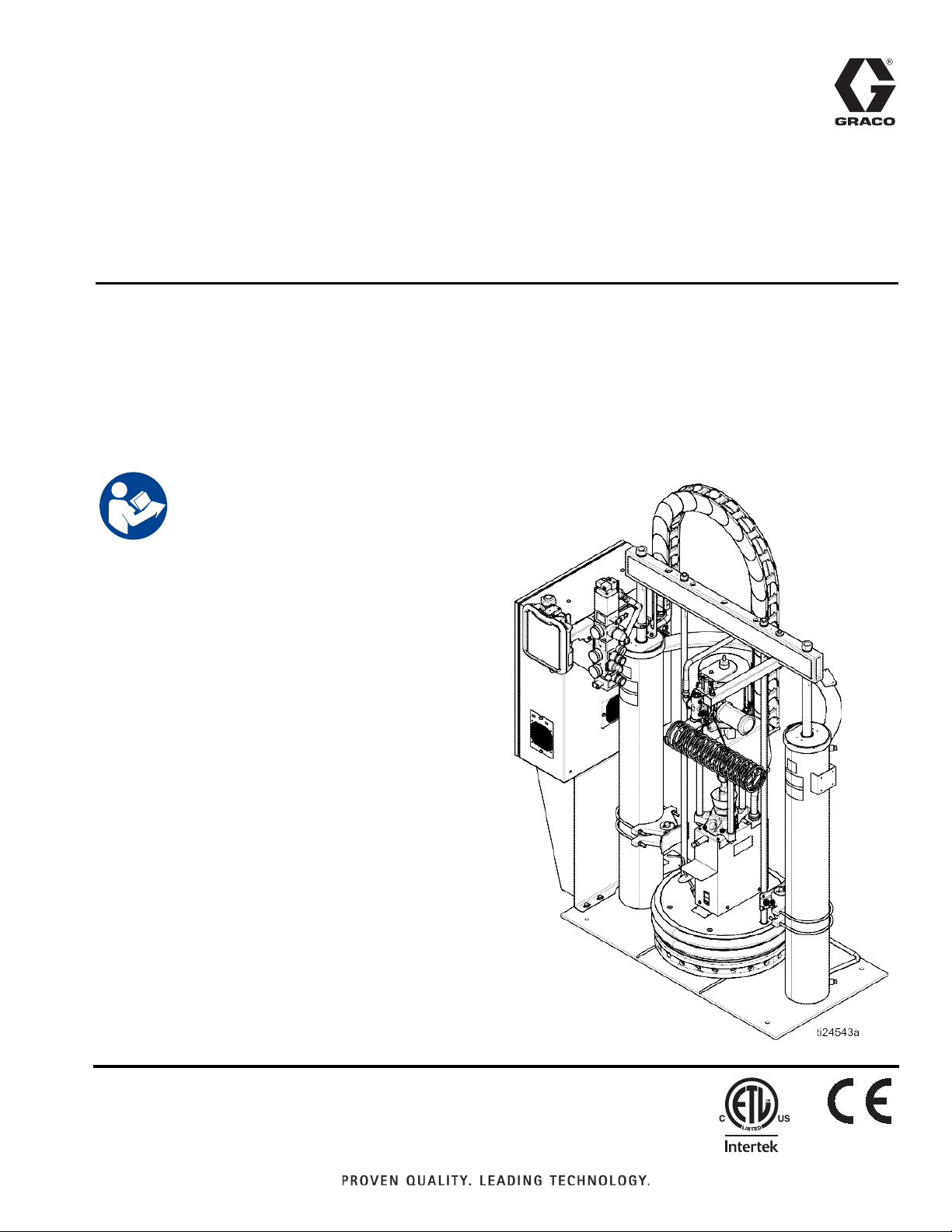
Therm-O-Flow
For applying hot melt sealant and adhesive materials from 200 Liter (55 Gallon) drums. For
professional use only.
Not approved for use in European explosive atmosphere locations.
Important Safety Instructions
Read all warnings and instructions in this manual
and in related manuals. Save these instructions.
Maximum Operating Temperature 400°F (204°C)
See page 7 for model information.
See Technical Specifications, page 113, for maximum
working pressures.
200
334130T
EN
3143485
Page 2

Contents
Warnings . . . . . . . . . . . . . . . . . . . . . . . . . . . . . . . . . . . . . . . 3
Models . . . . . . . . . . . . . . . . . . . . . . . . . . . . . . . . . . . . . . . . . 6
Related Manuals . . . . . . . . . . . . . . . . . . . . . . . . . . . . . . . . .7
Component Identification . . . . . . . . . . . . . . . . . . . . . . . . . 8
Integrated Air Controls . . . . . . . . . . . . . . . . . . . . . . . . . 9
Electrical Control Enclosure . . . . . . . . . . . . . . . . . . . . 10
Advanced Display Module (ADM) . . . . . . . . . . . . . . . . 11
Screen Components . . . . . . . . . . . . . . . . . . . . . . . . . . 13
Overview . . . . . . . . . . . . . . . . . . . . . . . . . . . . . . . . . . . . . . 14
Air and Fluid Hoses . . . . . . . . . . . . . . . . . . . . . . . . . . . 14
Heat Control Zone . . . . . . . . . . . . . . . . . . . . . . . . . . . 14
Setup . . . . . . . . . . . . . . . . . . . . . . . . . . . . . . . . . . . . . . . . . 15
Unpack . . . . . . . . . . . . . . . . . . . . . . . . . . . . . . . . . . . . 15
Location Requirements . . . . . . . . . . . . . . . . . . . . . . . . 15
Install System . . . . . . . . . . . . . . . . . . . . . . . . . . . . . . . 15
Install Hydraulic Power Supply . . . . . . . . . . . . . . . . . . 15
Mechanical Setup . . . . . . . . . . . . . . . . . . . . . . . . . . . .16
Install Heated Hose . . . . . . . . . . . . . . . . . . . . . . . . . . 17
Connect Multiple Devices . . . . . . . . . . . . . . . . . . . . . . 18
Connect Power . . . . . . . . . . . . . . . . . . . . . . . . . . . . . .19
Grounding . . . . . . . . . . . . . . . . . . . . . . . . . . . . . . . . . . 20
Connect Secondary System . . . . . . . . . . . . . . . . . . . . 20
Check Sensor Resistance . . . . . . . . . . . . . . . . . . . . . . 21
Check Heater Resistance . . . . . . . . . . . . . . . . . . . . . . 22
Select ADM Settings . . . . . . . . . . . . . . . . . . . . . . . . . .23
Connect PLC (Hard Wired Interface Version) . . . . . . . 25
Operation . . . . . . . . . . . . . . . . . . . . . . . . . . . . . . . . . . . . . 29
Purge System . . . . . . . . . . . . . . . . . . . . . . . . . . . . . . . 29
Load Material . . . . . . . . . . . . . . . . . . . . . . . . . . . . . . . 30
Heat Up System . . . . . . . . . . . . . . . . . . . . . . . . . . . . . 31
Prime Pump . . . . . . . . . . . . . . . . . . . . . . . . . . . . . . . . 32
Prime System . . . . . . . . . . . . . . . . . . . . . . . . . . . . . . . 34
Setback Mode . . . . . . . . . . . . . . . . . . . . . . . . . . . . . . . 34
Pressure Relief Procedure . . . . . . . . . . . . . . . . . . . . . 35
Stop Controls . . . . . . . . . . . . . . . . . . . . . . . . . . . . . . . 36
Shutdown . . . . . . . . . . . . . . . . . . . . . . . . . . . . . . . . . . 37
Schedule . . . . . . . . . . . . . . . . . . . . . . . . . . . . . . . . . . . 37
Change Drums . . . . . . . . . . . . . . . . . . . . . . . . . . . . . . 38
Troubleshooting . . . . . . . . . . . . . . . . . . . . . . . . . . . . . . . . 40
Light Tower (Optional) . . . . . . . . . . . . . . . . . . . . . . . . 40
Error Codes . . . . . . . . . . . . . . . . . . . . . . . . . . . . . . . . 41
Ram Troubleshooting . . . . . . . . . . . . . . . . . . . . . . . . . 47
Heated Pump Troubleshooting . . . . . . . . . . . . . . . . . . 48
Air Motor Troubleshooting . . . . . . . . . . . . . . . . . . . . . . 48
Repair . . . . . . . . . . . . . . . . . . . . . . . . . . . . . . . . . . . . . . . . 49
Replace Wipers . . . . . . . . . . . . . . . . . . . . . . . . . . . . . 49
Replace Platen RTD . . . . . . . . . . . . . . . . . . . . . . . . . . 49
Separate the Air Motor and Pump . . . . . . . . . . . . . . . 50
Remove Platen . . . . . . . . . . . . . . . . . . . . . . . . . . . . . . 53
Replace Heater Band and Pump RTD . . . . . . . . . . . . 53
Replace MZLP Fuse . . . . . . . . . . . . . . . . . . . . . . . . . . 54
Replace MZLP . . . . . . . . . . . . . . . . . . . . . . . . . . . . . . 55
Replace MZLP Daughter Card . . . . . . . . . . . . . . . . . . 56
Replace AWB . . . . . . . . . . . . . . . . . . . . . . . . . . . . . . . 57
Replace Power Supply . . . . . . . . . . . . . . . . . . . . . . . . 57
Replace Fan . . . . . . . . . . . . . . . . . . . . . . . . . . . . . . . . 58
Replace Transformer . . . . . . . . . . . . . . . . . . . . . . . . . 59
Update Software . . . . . . . . . . . . . . . . . . . . . . . . . . . . . 61
Electrical Schematics . . . . . . . . . . . . . . . . . . . . . . . . . . . 62
230V, 3 Phase/60Hz . . . . . . . . . . . . . . . . . . . . . . . . . . 62
400V, 3 Phase/50Hz . . . . . . . . . . . . . . . . . . . . . . . . . . 63
400-600VV, 3 Phase/60Hz . . . . . . . . . . . . . . . . . . . . . 64
AWB and MZLP#1 . . . . . . . . . . . . . . . . . . . . . . . . . . . 65
MZLP#2, MZLP#3, Overtemp, and Pump Heaters . . . 66
MZLP Zones . . . . . . . . . . . . . . . . . . . . . . . . . . . . . . . . 67
Parts . . . . . . . . . . . . . . . . . . . . . . . . . . . . . . . . . . . . . . . . . 68
Therm-O-Flow 200 Supply Unit . . . . . . . . . . . . . . . . . 68
Therm-O-Flow 200 Supply Unit . . . . . . . . . . . . . . . . . 69
Air Control Assembly . . . . . . . . . . . . . . . . . . . . . . . . . 70
Electrical Module . . . . . . . . . . . . . . . . . . . . . . . . . . . . 71
Electrical Control Module Parts . . . . . . . . . . . . . . . . . 73
Electrical Panel . . . . . . . . . . . . . . . . . . . . . . . . . . . . . . 75
230V . . . . . . . . . . . . . . . . . . . . . . . . . . . . . . . . . . . . . . 75
400V . . . . . . . . . . . . . . . . . . . . . . . . . . . . . . . . . . . . . . 75
Transformer . . . . . . . . . . . . . . . . . . . . . . . . . . . . . . . . 75
Electrical Panel Parts . . . . . . . . . . . . . . . . . . . . . . . . . 77
Merkur 2200, 23:1 Pump Modules . . . . . . . . . . . . . . . 78
Merkur 2200, 23:1 Pump Modules . . . . . . . . . . . . . . . 79
Merkur 3400, 36:1 Pump Modules . . . . . . . . . . . . . . . 80
Merkur 3400, 36:1 Pump Modules . . . . . . . . . . . . . . . 81
NXT 6500, 70:1 Pump Modules . . . . . . . . . . . . . . . . . 82
NXT 6500, 70:1 Pump Modules . . . . . . . . . . . . . . . . . 83
24V619, Pump Shield . . . . . . . . . . . . . . . . . . . . . . . . . 84
Heated Platens . . . . . . . . . . . . . . . . . . . . . . . . . . . . . . 85
24V633, Heated Drum Platen, Mega-Flo
(Code E-option M) . . . . . . . . . . . . . . . . . . . . . . . . 85
24V634, Heated Drum Platen, Standard Grid
(Code E-option F) . . . . . . . . . . . . . . . . . . . . . . . . 85
24V635, Heated Drum Platen, Smooth Bottom (no fin)
(Code E- option S) . . . . . . . . . . . . . . . . . . . . . . . . 85
Heated Platens . . . . . . . . . . . . . . . . . . . . . . . . . . . . . . 86
24V633, Heated Drum Platen, Mega-Flo
(Code E-option M) . . . . . . . . . . . . . . . . . . . . . . . . 86
24V634, Heated Drum Platen, Standard Grid
(Code E-option F) . . . . . . . . . . . . . . . . . . . . . . . . 86
2 334130T
Page 3

24V635, Heated Drum Platen, Smooth Bottom (no fin)
(Code E- option S) . . . . . . . . . . . . . . . . . . . . . . . 86
Drum Ram Post Saddle Clamp . . . . . . . . . . . . . . . . . 88
C32463 . . . . . . . . . . . . . . . . . . . . . . . . . . . . . . . . . . . 88
Option H-1 . . . . . . . . . . . . . . . . . . . . . . . . . . . . . . . . . 88
Drum Ram Post Saddle Clamp . . . . . . . . . . . . . . . . . 89
918395 . . . . . . . . . . . . . . . . . . . . . . . . . . . . . . . . . . . . 89
Option H-3 . . . . . . . . . . . . . . . . . . . . . . . . . . . . . . . . . 89
Fiber Drum Reinforcement Shell Clamp . . . . . . . . . . 90
918397 . . . . . . . . . . . . . . . . . . . . . . . . . . . . . . . . . . . . 90
Option H-2 . . . . . . . . . . . . . . . . . . . . . . . . . . . . . . . . . 90
Vent Hood Kit, 233559 . . . . . . . . . . . . . . . . . . . . . . . . 91
Accessories and Kits . . . . . . . . . . . . . . . . . . . . . . . . . . . 92
Wiper Kits . . . . . . . . . . . . . . . . . . . . . . . . . . . . . . . . . . 92
Applicators and Dispense Valves . . . . . . . . . . . . . . . . 92
CGM Installation Kit, 25C994 . . . . . . . . . . . . . . . . . . . 92
Flow Control and Manifolds . . . . . . . . . . . . . . . . . . . . 92
Accessory Extension Cables . . . . . . . . . . . . . . . . . . . 93
Light Tower Kit, 24W589 . . . . . . . . . . . . . . . . . . . . . . 93
Heated Hoses and Fittings . . . . . . . . . . . . . . . . . . . . . 94
8 Channel Upgrade Kit, 24V755 . . . . . . . . . . . . . . . . 96
8 Zone Upgrade Kit Installation . . . . . . . . . . . . . . . . . 97
12 Channel Upgrade Kit, 24V756 . . . . . . . . . . . . . . . 98
12 Zone Upgrade Kit Installation . . . . . . . . . . . . . . . . 99
Appendix A - ADM . . . . . . . . . . . . . . . . . . . . . . . . . . . . . 100
General Operation . . . . . . . . . . . . . . . . . . . . . . . . . . 100
ADM Power . . . . . . . . . . . . . . . . . . . . . . . . . . . . . . . 100
Screen Navigation . . . . . . . . . . . . . . . . . . . . . . . . . . 100
Enable, Disable Heating System . . . . . . . . . . . . . . . 100
Icons . . . . . . . . . . . . . . . . . . . . . . . . . . . . . . . . . . . . 101
Operation Screens . . . . . . . . . . . . . . . . . . . . . . . . . . 102
Setup Screens . . . . . . . . . . . . . . . . . . . . . . . . . . . . . 104
Appendix B - USB Data . . . . . . . . . . . . . . . . . . . . . . . . . 109
Download . . . . . . . . . . . . . . . . . . . . . . . . . . . . . . . . . 109
Access Files . . . . . . . . . . . . . . . . . . . . . . . . . . . . . . . 109
Upload . . . . . . . . . . . . . . . . . . . . . . . . . . . . . . . . . . . 109
USB Logs . . . . . . . . . . . . . . . . . . . . . . . . . . . . . . . . . 110
System Settings File . . . . . . . . . . . . . . . . . . . . . . . . 110
System Language File . . . . . . . . . . . . . . . . . . . . . . . 111
Create Custom Language Strings . . . . . . . . . . . . . . 111
Dimensions . . . . . . . . . . . . . . . . . . . . . . . . . . . . . . . . . . 112
Ram Mounting and Clearance . . . . . . . . . . . . . . . . . 112
Technical Specifications . . . . . . . . . . . . . . . . . . . . . . . 113
California Proposition 65 . . . . . . . . . . . . . . . . . . . . . . . 113
Graco Standard Warranty . . . . . . . . . . . . . . . . . . . . . . . 114
334130T 3
Page 4
Warnings
WARNING
Warnings
The following warnings are for the setup, use, grounding, maintenance, and repair of this equipment. The exclama-
tion point symbol alerts you to a general warning and the hazard symbols refer to procedure-specific risks. When
these symbols appear in the body of this manual or on warning labels, refer back to these Warnings. Product-specific
hazard symbols and warnings not covered in this section may appear throughout the body of this manual where
applicable.
BURN HAZARD
Equipment surfaces and fluid that is heated can become very hot during operation. To avoid
burns:
• Do not touch hot fluid or equipment.
SPLATTER HAZARD
severe
Hot or toxic fluid can cause serious injury if splashed in the eyes or on skin. During blow off of platen,
splatter may occur.
• Use minimum air pressure when removing platen from drum.
MOVING PARTS HAZARD
Moving parts can pinch, cut or amputate fingers and other body parts.
• Keep clear of moving parts.
• Do not operate equipment with protective guards or covers removed.
• Pressurized equipment can start without warning. Before checking, moving, or servicing equipment,
follow the Pressure Relief Procedure and disconnect all power sources.
ELECTRIC SHOCK HAZARD
This equipment must be grounded. Improper grounding, setup, or usage of the system can cause electric
shock.
• Turn off and disconnect power at main switch before disconnecting any cables and before servicing or
installing equipment.
• Connect only to grounded power source.
• All electrical wiring must be done by a qualified electrician and comply with all local codes and regu-
lations.
TOXIC FLUID OR FUMES HAZARD
Toxic fluids or fumes can cause serious injury or death if splashed in the eyes or on skin, inhaled, or
swallowed.
• Read MSDSs to know the specific hazards of the fluids you are using.
• Store hazardous fluid in approved containers, and dispose of it according to applicable
4 334130T
guidelines.
Page 5
THERMAL EXPANSION HAZARD
WARNING
Fluids subjected to heat in confined spaces, including hoses, can create a rapid rise in pressure
the thermal expansion. Over- pres su riz ation can resu lt in equi pm ent ru pture and se rious
• Open a valve to relieve the fluid expansion during heating.
• Replace hoses proactively at regular intervals based on your operating conditions.
SKIN INJECTION HAZARD
High-pressure fluid from dispensing device, hose leaks, or ruptured components will pierce
may look like just a cut, but it is a serious injury that can result in amputation. Get
treatment.
injury.
skin. This
immediate surgical
Warnings
due to
• Engage trigger lock when not dispensing.
• Do not point dispensing device at anyone or at any part of the body.
• Do not put your hand over the fluid outlet.
• Do not stop or deflect leaks with your hand, body, glove, or rag.
• Follow the Pressure Relief Procedure when you stop dispensing and before cleaning, checking, or
servicing equipment.
• Tighten all fluid connections before operating the equipment.
• Check hoses and couplings daily. Replace worn or damaged parts immediately.
FIRE AND EXPLOSION HAZARD
Flammable fumes, such as solvent and paint fumes, in work area can ignite or explode. To help
fire and explosion:
• Use equipment only in well ventilated area.
• Eliminate all ignition sources; such as pilot lights, cigarettes, portable electric lamps, and
cloths (potential static arc).
• Keep work area free of debris, including solvent, rags and gasoline.
• Do not plug or unplug power cords, or turn power or light switches on or off when flammable
present.
• Ground all equipment in the work area. See Grounding instructions.
• Use only grounded hoses.
• Hold gun firmly to side of grounded pail when triggering into pail. Do not use pail liners unless
antistatic or conductive.
• Stop operation immediately if static sparking occurs or you feel a shock. Do not use
you identify and correct the problem.
• Keep a working fire extinguisher in the work area.
equipment until
prevent
plastic drop
fumes are
they are
334130T 5
Page 6
Warnings
WARNING
EQUIPMENT MISUSE HAZARD
Misuse can cause death or serious injury.
• Do not operate the unit when fatigued or under the influence of drugs or alcohol.
• Do not exceed the maximum working pressure or temperature rating of the lowest rated
ponent. See Technical Data in all equipment manuals.
• Use fluids and solvents that are compatible with equipment wetted parts. See Technical Data in all
equipment manuals. Read fluid and solvent manufacturer’s warnings. For complete
your material, request MSDS from distributor or retailer.
• Do not leave the work area while equipment is energized or under pressure.
• Turn off all equipment and follow the Pressure Relief Procedure when equipment is not in use.
• Check equipment daily. Repair or replace worn or damaged parts immediately with genuine
turer’s replacement parts only.
• Do not alter or modify equipment. Alterations or modifications may void agency approvals
safety hazards.
• Make sure all equipment is rated and approved for the environment in which you are using it.
• Use equipment only for its intended purpose. Call your distributor for information.
• Route hoses and cables away from traffic areas, sharp edges, moving parts, and hot surfaces.
• Do not kink or over bend hoses or use hoses to pull equipment.
• Keep children and animals away from work area.
• Comply with all applicable safety regulations.
system com-
information about
manufac-
and create
PERSONAL PROTECTIVE EQUIPMENT
Wear appropriate protective equipment when in the work area to help prevent serious injury,
eye injury, hearing loss, inhalation of toxic fumes, and burns. This protective
not limited to:
• Protective eyewear, and hearing protection.
• Respirators, protective clothing, and gloves as recommended by the fluid and solvent
equipment includes but is
including
manufacturer.
6 334130T
Page 7
Models
The model number stamped on your systems defines the equipment in the following categories.
See Technical Specifications, page 113, for maximum working pressure.
SER A B C D E F G H
Series Frame Size Air
Air/Electric
Zone
Config
Pump
Ratio
Platen
Style
Platen
Seal
Ram Drum
Models
Clamp
Code A Frame Size
200 55 Gallon (200 Liter)
Code B Air/Electric
A Air control only
E Air and Electric
Code C Zones, Volts, Type
11P 4 Zones, 230 V, Primary
11S 4 Zones, 230 V, Secondary
12P 4 Zones, 400 V/N, Primary
12S 4 Zones, 400 V/N, Secondary
13P 4 Zones, 400 V, Primary
13S 4 Zones, 400 V, Secondary
14P 4 Zones, 480 V, Primary
14S 4 Zones, 480 V, Secondary
15P 4 Zones, 600 V, Primary
15S 4 Zones, 600 V, Secondary
21P 8 Zones, 230 V, Primary
21S 8 Zones, 230 V, Secondary
22P 8 Zones, 400 V/N, Primary
22S 8 Zones, 400 V/N, Secondary
23P 8 Zones, 400 V, Primary
23S 8 Zones, 400 V, Secondary
24P 8 Zones, 480 V, Primary
24S 8 Zones, 480 V, Secondary
25P 8 Zones, 600 V, Primary
25S 8 Zones, 600 V, Secondary
31P 12 Zones, 230 V, Primary
31S 12 Zones, 230 V, Secondary
32P 12 Zones, 400 V/N, Primary
32S 12 Zones, 400 V/N, Secondary
33P 12 Zones, 400 V, Primary
33S 12 Zones, 400 V, Secondary
34P 12 Zones, 480 V, Primary
34S 12 Zones, 480 V, Secondary
35P 12 Zones, 600 V, Primary
35S 12 Zones, 600 V, Secondary
NNN None
Code D Pump Ratio
1 23:1 CF (carbon filled PTFE)
236:1
370:1
4 23:1 (glass filled PTFE)
536:1
670:1
Code E Platen Style
S Smooth Bottom (No Fin)
F Standard Finned Bottom
M Mega-Flo
Code F Platen Seal
1 2 Black EPDM/EPDM, SS wire braid 400°F
(204°C) hose wipers with spring retention
2 1 lower black EPDM/Chlorobutyl, SS wire
braid 400°F (204°C) hose wiper and 1
upper Green Silicone, fiberglass braid
400°F (204°C), hose wiper
3 2 White Silicone 250°F (121°C) T-Wipers
4 1 lower black EPDM/Chlorobutyl, SS wire
braid 375°F (190°C) hose wiper and 1
upper White Silicone 375°F (190°C),
T-wiper
5 2 Orange silicone o-ring 400°F (204°C)
Code G Ram
P Pneumatic
H Hydraulic
Code H Drum Clamps
NNone
1 Saddle Clamp
2 Fiber Clam Shell
3 Heavy Drum Band
334130T 7
Page 8

Related Manuals
Related Manuals
Manual Description
334129 Therm-O-Flow 20, Instructions-Parts
3A5186 Communications Gateway Module
Therm-O-FLow
Air Motor Manuals
311238
3A1211
Displacement Pump Manual
334127
334128
Ram Manual
334198 Therm-O-Flow 200 Pneumatic and
Accessory and Kit Manuals
3A4241 Heated Hose, Instructions-Parts
309160 Heated Hose, Instructions-Parts
309196 Wiper Kits, Repair-Parts
310538 Air-Operated Dispense Valves,
311209 Top Feed and Bottom Feed Hot Melt
334201 Air Controls, Repair Kit
®
Air Motor, Instructions-Parts
NXT
®
Saniforce
Check-Mate
Check-Mate
Air Motor, Instructions-Parts
®
800 Pump, Repair-Parts
®
800 Throat Seal Repair Kit,
Repair-Parts
Hydraulic Ram, Instructions-Parts
tions-Parts
pense Guns, Instructions-Parts
Instruc-
Dis-
8 334130T
Page 9
Component Identification
C
M
D
A
P
B
T
J
N
L
K
H
R, S
G
E
ti24544a
F
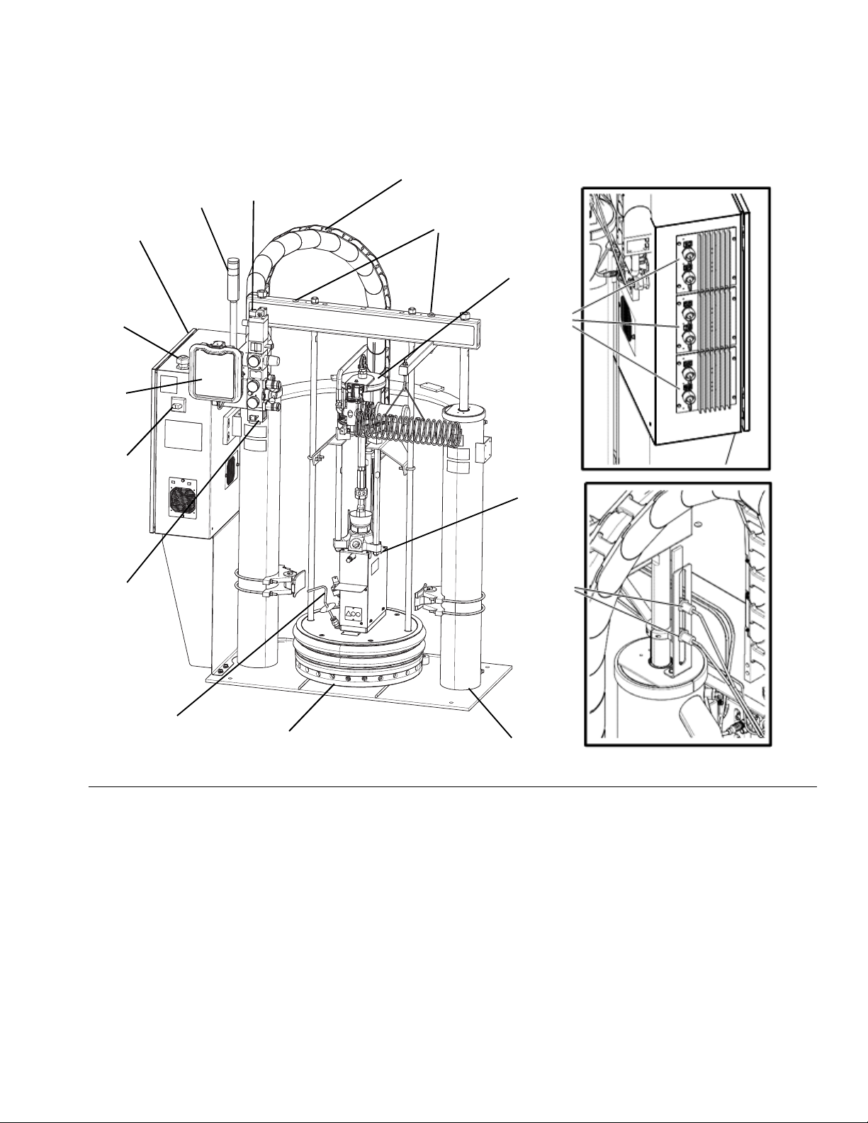
Component Identification
FIG. 1: TOF 200 Pneumatic
Key:
A Lift Strap Positions
B Multi-Zone Low Power Temperature Control Module
(MZLP)
C Light Tower
D Cable Track
ERam
F Heated Pump
G Heated Platen
H Integrated Air Controls (3/4 in npt inlet)
J Electrical Control Panel
K Main Power Switch (can be locked in the open position)
LADM
M Air Motor Solenoid
N Electrical Power Input
P Air Motor
R Ram Plate Bleed Stick
S Drum Blow Off Valve (behind ram plate bleed stick)
T Drum Low and Empty Sensors
334130T 9
Page 10
Component Identification
CN
CM
CK
CJ
CH
CD
CC
CB
CA
CE
CG
CF
CL
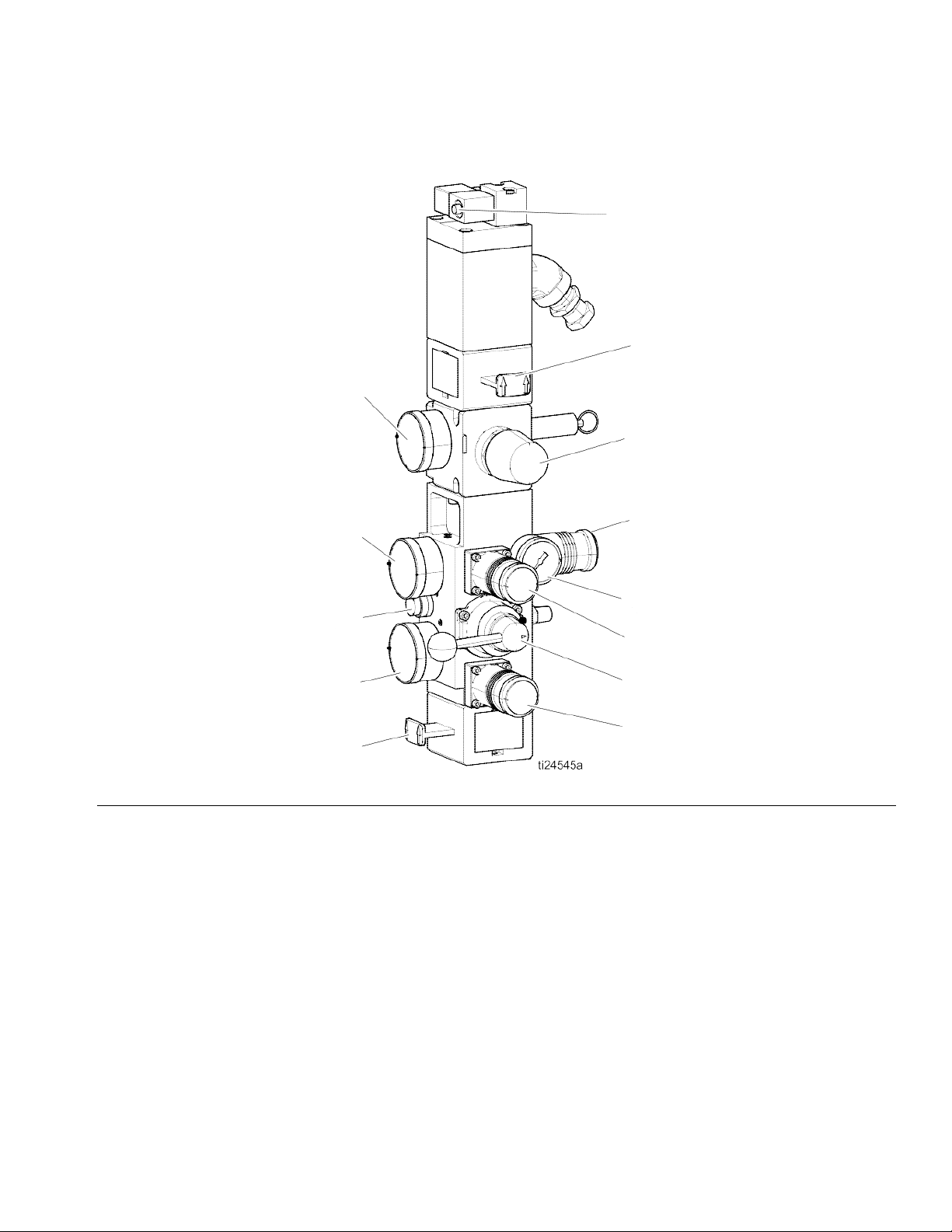
Integrated Air Controls
FIG. 2: Integrated Air Controls
Key:
CA
Main Air Slider Valve
Turns air on and off to the entire system. When closed,
the valve relieves pressure downstream. Can be locked in
the closed position.
Ram Down Air Regulator
CB
Controls the ram down pressure.
Ram Director Valve
CC
Controls the ram direction.
Ram Up Air Regulator
CD
Controls the ram up pressure.
CE
Ram Down Air Gauge
Displays the ram down pressure.
Ram Up Air Gauge
CF
Displays the ram up pressure.
Blowoff Button
CG
Turns air on and off to push the platen out of an empty
drum.
CH
Blowoff Pressure Gauge
Displays the blowoff pressure.
Blowoff Air Regulator
CJ
Controls platen blowoff pressure.
Air Motor Air Regulator
CK
Controls the air pressure to the motor.
Air Motor Pressure Gauge
CL
Displays the air pressure to the motor.
Air Motor Slider Valve
CM
Turns air on and off to the air motor. When closed, the
valve relieves air trapped between it and the motor. Push
the valve in to shut off air. Can be locked in the closed
position.
Air Motor Solenoid Valve
CN
Turns air on and off to the air motor when system stopped
on the ADM. When closed, the valve relieves air trapped
between it and the motor.
10 334130T
Page 11
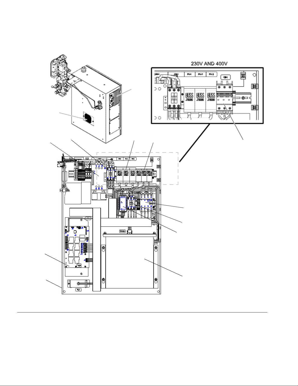
Electrical Control Enclosure
Back Panel With Transformer
DL
DJ
DH
DG
DF
DN
DE
DM
DC
DD
DB
DA
DK
Component Identification
FIG. 3: Electrical Enclosure
Key:
DA Multi-Zone Low Power Temperature Control Module
(MZLP)
DB Ventilation Grill
DC Electrical Control Panel
DD Automatic Wiring Board (AWB)
DE Power Supply (24V)
DF Residual Current Device (GFI), 63A
334130T 11
DG Platen SSR (65A)
DH Platen Contractor
DJ Platen Fuse
DK Transformer Circuit Breaker
DL Transformer Fuse
DM Transformer
DN System Contactor
Page 12
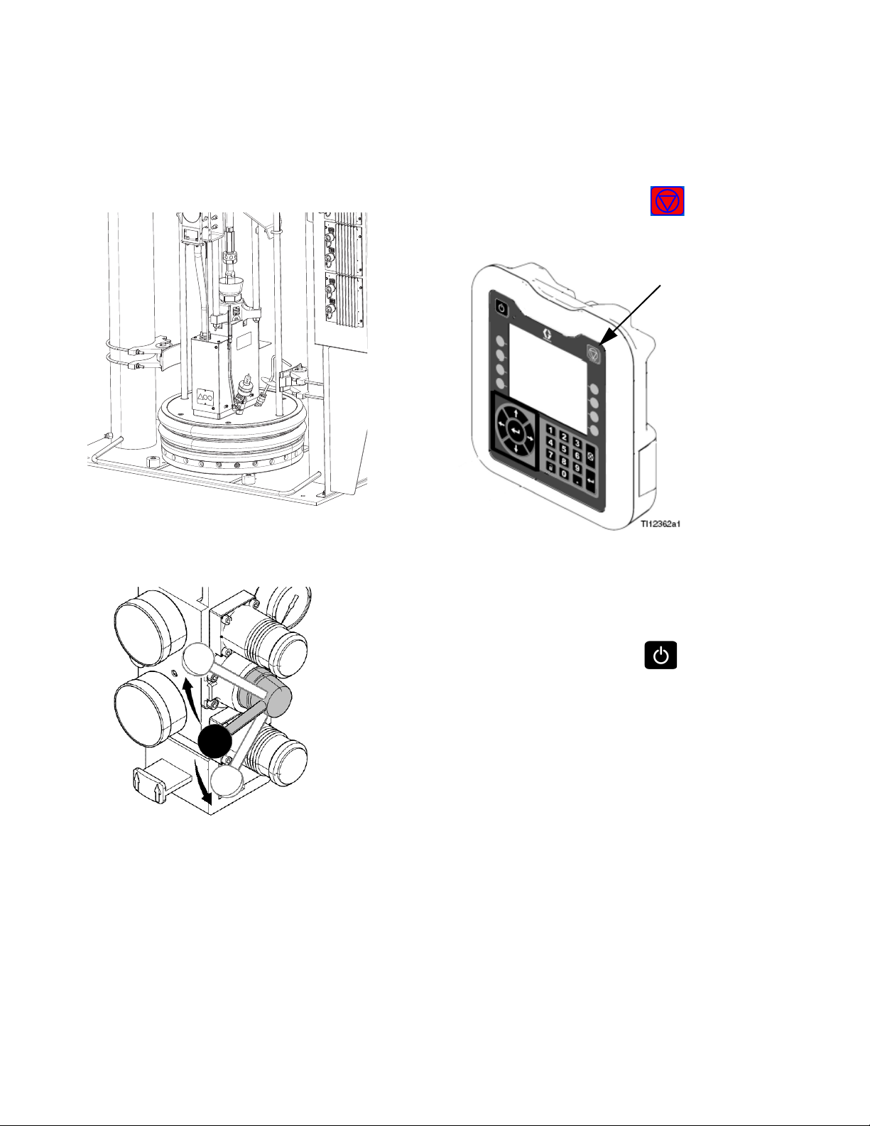
Component Identification
BB
BC
BD
BE
BF
BA
BH
BG
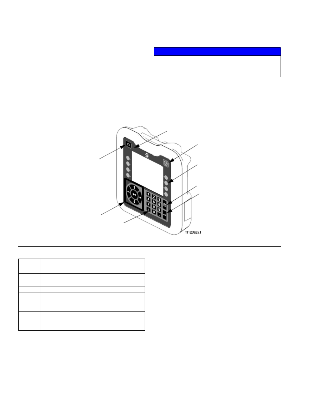
System Shutdown
Enable/Disable
Advanced Display Module (ADM)
The ADM display shows graphical and text information
related to setup and spray operations. For detail on the
display and individual screens, see Appendix A - ADM,
page 100.
Use the USB port on the ADM to download or upload
ta. For more information about the USB data, see
pendix B - USB Data, page 109.
Ap-
da-
NOTICE
To prevent damage to the softkey buttons, do not
press buttons with sharp objects such as pens, plastic
cards, or fingernails.
FIG. 4: Front View
Key Function
BA Heating system and Pump Enable/Disable
BB System status indicator (LED)
BC Stop all system processes
BD Defined by icon next to softkey
BE Abort current operation
BF Accept change, acknowledge error, select
item, toggle selected item
BG Toggle between Operation and Setup
screens
BH Navigate within a screen or to a new screen
12 334130T
Page 13
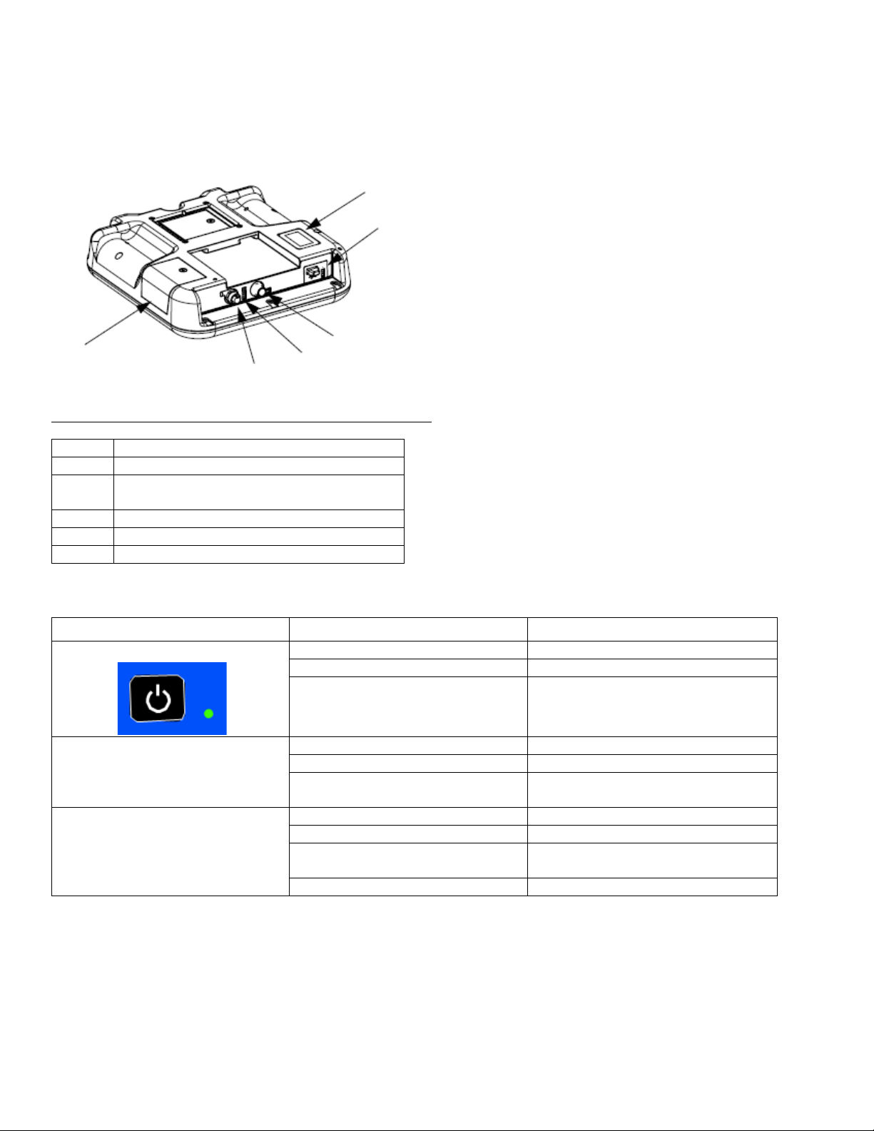
FIG. 5: Back View
BK
BL
BM
BN
BP
BR
BK Part Number and Identification Label
BL USB Interface
BM CAN Cable Connection (Power Supply and
Communication)
BN Module Status LEDs
BP Light Tower (Optional)
BR Software Token Access Panel
Component Identification
Table 1 ADM LED Status Descriptions
LED Conditions Description
System Status Green Solid Run Mode, System On
Green Flashing Setup Mode, System On
Yellow Solid Run Mode, System Off
USB Status (BL) Green Flashing Data recording in progress
Yellow Solid Downloading information to USB
Green and Yellow Flashing ADM is busy, USB cannot transfer
information when in this mode
ADM Status (BN) Green Solid Power applied to module
Yellow Solid Active Communication
Red Steady Flashing Software upload from token in prog-
ress
Red Random Flashing or Solid Module error exists
334130T 13
Page 14
Component Identification
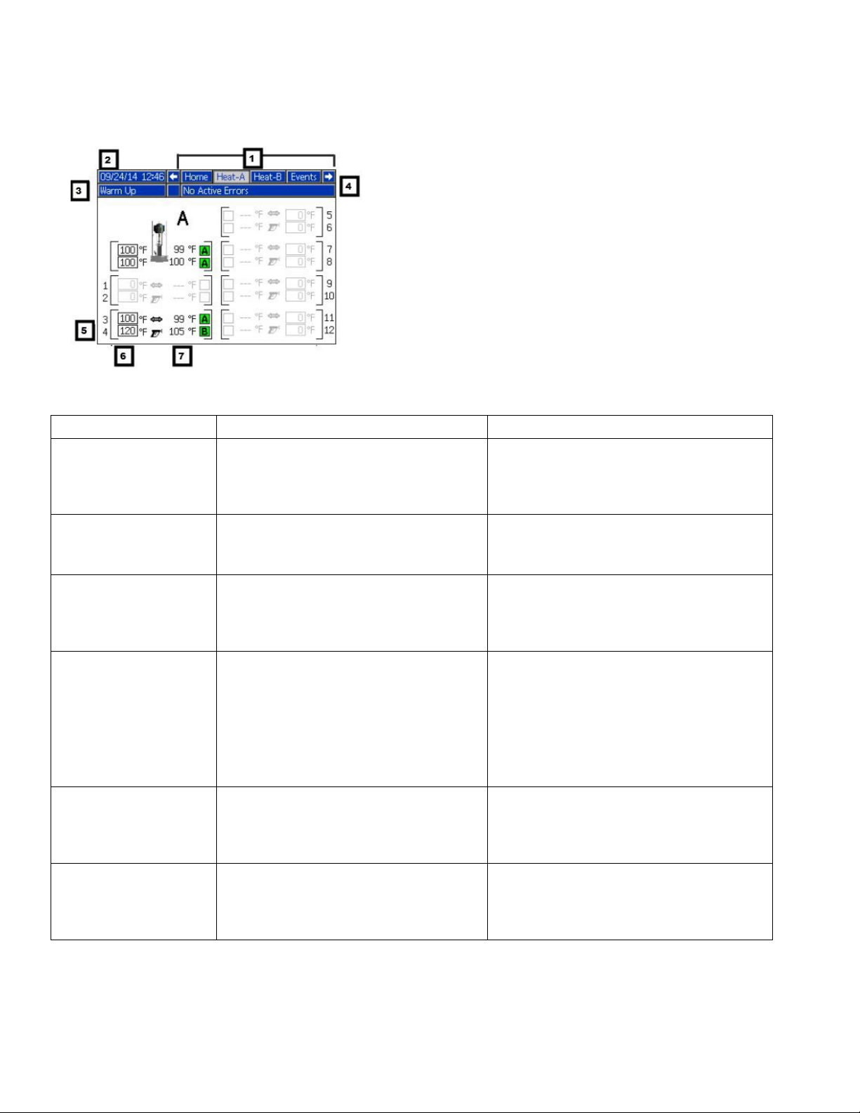
Screen Components
1. Screen Order
2. Current date and time
3. Operating Mode
4. Faults, Status
5. MZLP Plug Identifier
6. Zone Setpoint Temperature
7. Zone Actual Temperature
Operating Mode Description Component Status
System Off The system does not have power. • No system status indicator LED on the
ADM
• No heat
• Pump is off
Inactive The heating system and pumps are dis-
abled.
Warm Up The system is heating the material to the
setpoint temperature.
Heat Soak Heat zones are all at temperature. Material
is soaking for a user specified amount of
time.
Ready All enabled zones are at setpoint tempera-
ture. The Air Motor does not have power.
Active The system is ready to dispense. • Solid green system status indicator LED
• Yellow system indicator LED on the ADM
• No heat
• Pump is off
• Flashing green system status indicator
LED on the ADM
• Heat is increasing to setpoint temperature
• Pump is off
• Flashing green system status indicator
LED on the ADM
• Heat is at setpoint
• Material is absorbing more heat
• Pump is off
• Heat soak counter counts down on the
Home screen.
• Flashing green system status indicator
LED on the ADM
• Heat is at setpoint
• Pump is off
on the ADM
• Heat is at setpoint temperature
• Pump is on
14 334130T
Page 15
Overview
Overview
A Heated Platen melts the sealant or adhesive and
rects the molten material to the Pump inlet. The
then travels through a Heated Pump and
moves to the application tool.
heated fluid
material
di-
Air and Fluid Hoses
The Therm-O-Flow requires Graco single-circuit
rial hoses rated at a maximum of 1250 watts.
all air and fluid hoses are properly sized
for the system.
mate-
Make sure
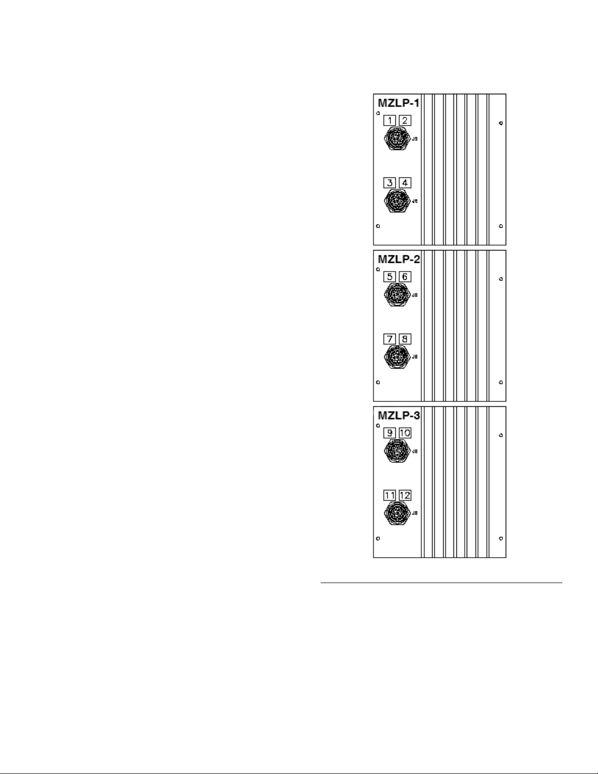
Heat Control Zone
The Therm-O-Flow has 4, 8, or 12 heat zones. Zones
for the Heated Drum Platen and the Heated Pump are
not included in the zone count. Zones 1 and 2,
5 and 6, 7 and 8, 9 and 10, and 11 and
available through 12-pin connectors. The heated hoses
have a 16-pin connector at the
nector at the outlet. All heated
heaters are equipped with an
inlet, and an 8-pin con-
valves, manifolds, and
8-pin mating connector.
12 are each
3 and 4,
FIG. 6: Heat Control Zone Selection
334130T 15
Page 16

Setup
Setup
1. Unpack the Ram
2. Locate and Install the Ram
3. Mechanical Setup
4. Connect hoses to Electrical Control Panel
5. Connect Electrical Control Panel to power source
6. Ground system
7. Select ADM settings
Unpack
1. Inspect the shipping box carefully for damage. Con-
tact the carrier promptly if there is damage.
2. Open the box and inspect the contents carefully.
There should not be any loose or damaged parts in
the box.
3. Compare the packing slip against all items in the
box. Repost any shortages or other inspection prob-
lems immediately.
4. Remove the unit from the skid and place it in the
desired location. See Location Requirements.
5. Make sure there is easy access to an appropriate
electrical power source. The National Electrical
Code requires 3 ft (0.9 m) of open space in front of
the electrical panel. Comply with all local codes and
regulations.
6. For hydraulic rams, locate the hydraulic power sup-
ply in an area that has:
• easy access for servicing and adjusting the
hydraulic pressure on the supply unit
• sufficient clearance for the hydraulic lines that
attach to the Pump
• easy access to read the hydraulic fluid level
gauge
Install System
Refer to Dimensions, page 112 for mounting and
ance dimensions.
Follow all Location Requirements, page 16, when
selecting a location for the Ram.
1. Apply 50 psi download pressure to Ram.
2. Wrap the bar with the lifting sling.
clear-
Location Requirements
1. Make sure there is sufficient overhead clearance for
the Heated Pump and Ram when the Ram is in the
fully raised position (approximately 110 in. (280
cm)).
2. If you are installing a vent hood, make sure there is
sufficient horizontal clearance for it. Locate the Ram
near a connection to the factory ventilation system.
3. Make sure the air regulators for the Heated Pump
and Ram are fully accessible, with room to stand
directly in front of the Pneumatic Control Panel and
the Electrical Control Panel.
4. When locating the system, do not install closer than
36 in. (914 mm) to vertical surfaces.
3. Lift the system off the pallet using a crane or a
lift and place in desired location.
4. Level the base of the Ram, using metal shims.
5. Bolt the Ram to the floor, using anchors that are
long enough to prevent the unit from tipping.
fork-
Install Hydraulic Power Supply
See the Ram manual for installation and dimensions.
16 334130T
Page 17
Setup
H
B
A
C1
C2
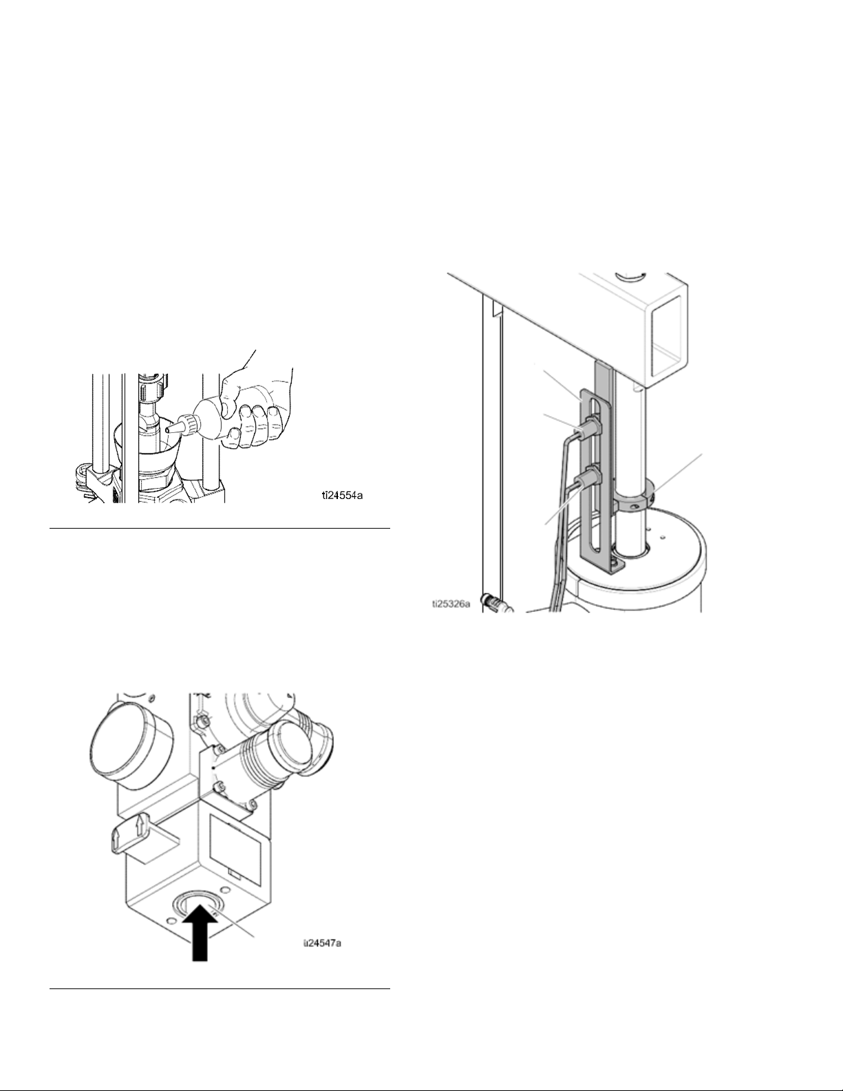
Mechanical Setup
1. Fill displacement Pump wet cup 2/3 full with Graco
Throat Seal Liquid (TSL™) for Butyl and PSA mate-
rials.
NOTE: Use IsoGuard Select
for PUR or reactive Polyurethane material. IGS is
designed to dissolve and suspend the Polyurethane
materials. IGS will solidify after a period of time and
should be replaced once the solidified lube does not
return to liquid form after heating.
®
(IGS) (part no. 24F516)
4. Ensure Drum Low and Empty Sensors (C) are
mounted as shown.
NOTE: The Drum Low and Empty Sensors are
indicate that a drum is empty.
mounting
and a cable for connecting the panel
Enclosure.
bracket (A), activator (B), sensors (C1, C2),
The kit contains a sensor
inside the Electrical
used to
FIG. 7: Wetcup
2. Turn all air regulators to their full counterclockwise
position. See Integrated Air Controls, page 10.
3. Connect a 1/2 in. (13 mm) air line from an air source
to the system air inlet (H), capable of delivering a
minimum of 25-50 cfm at 100 psi (0.7 MPa, 7.0 bar).
Do not use quick disconnects.
5. Increase the distance between the low (C1) and
empty (C2) sensors to increase the heat up time for
the tandem secondary system. Lower the drum
empty sensor (C2) to force the Heated Platen lower
into the drum. If empty sensor is set too low, the
Pump could cavitate and cause an alarm.
FIG. 8: Air Connection
334130T 17
Page 18
Setup
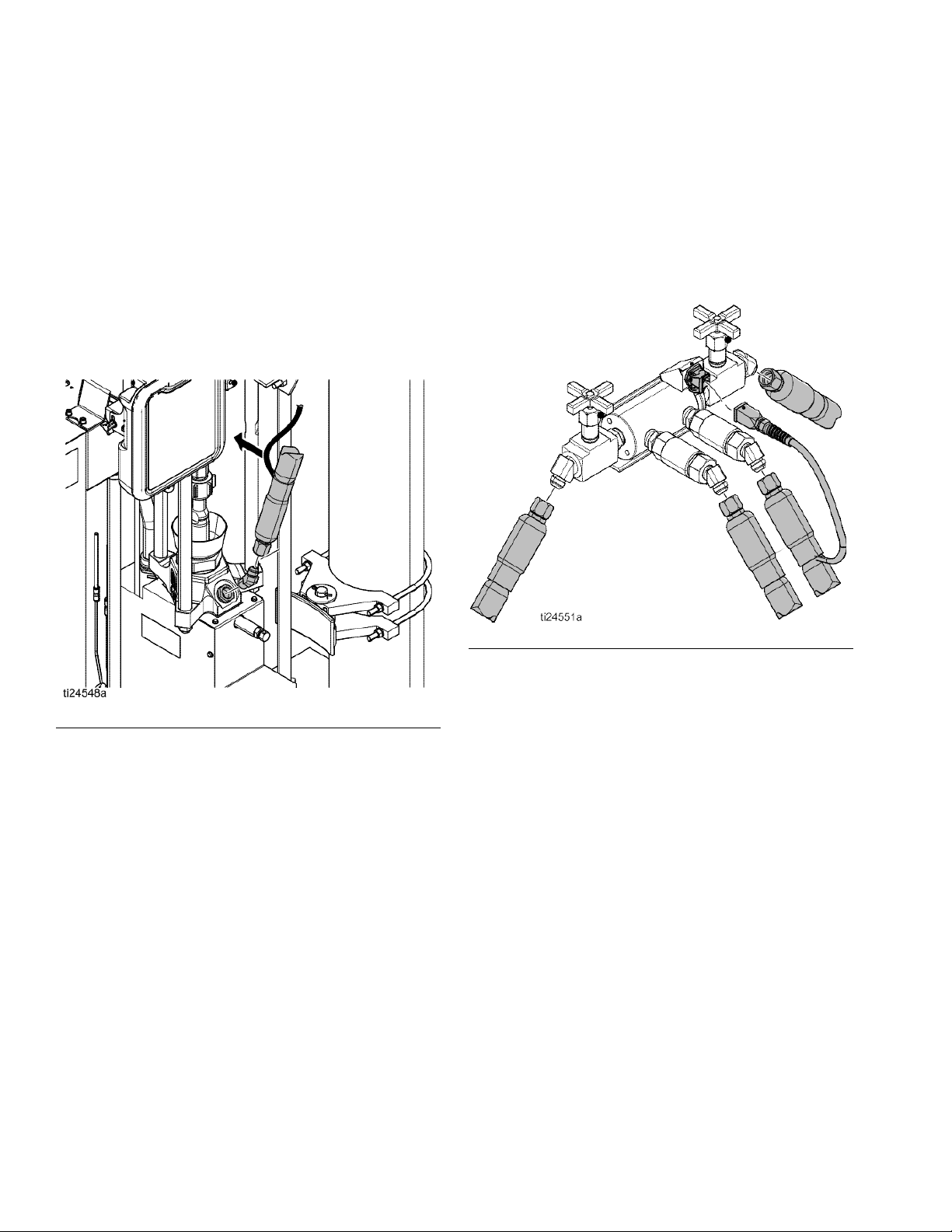
Install Heated Hose
To connect a hose to a fluid control device or heated
manifold.
1. Install fitting and heated hose onto Pump outlet with
the large electrical connector side toward the sys-
tem. Use 2 wrenches to tighten hose. Torque to 45
ft-lbs (61 N•m).
NOTE: See Accessories and Kits, page 92, for avail-
able fittings and heated hoses.
5. For proper operation, cables must be plugged into
zones 1–2 and 3–4 at all times.
6. Install cap on any unused MZLP electrical connec-
tors.
7.
Connect the small 8 pin connector from the heated
hose to the fluid control device or heated manifold.
FIG. 9
2. Wrap exposed fittings on the Pump outlet with
Nomex insulation and secure insulation using fiber-
glass tape.
3. Connect large heated hose connector to MZLP.
4. Repeat for any remaining channels.
FIG. 10: Heated Manifold 243697
NOTE: The heated manifold (part no. 243697) shown.
See Accessories and Kits, page 92, for available man-
ifolds and fluid control devices.
8. Use 2 wrenches to tighten hose. Torque to 45 ft-lbs
(61 N•m).
9. To connect multiple devices, see Connect Multiple
Devices, page 19.
18 334130T
Page 19
Setup
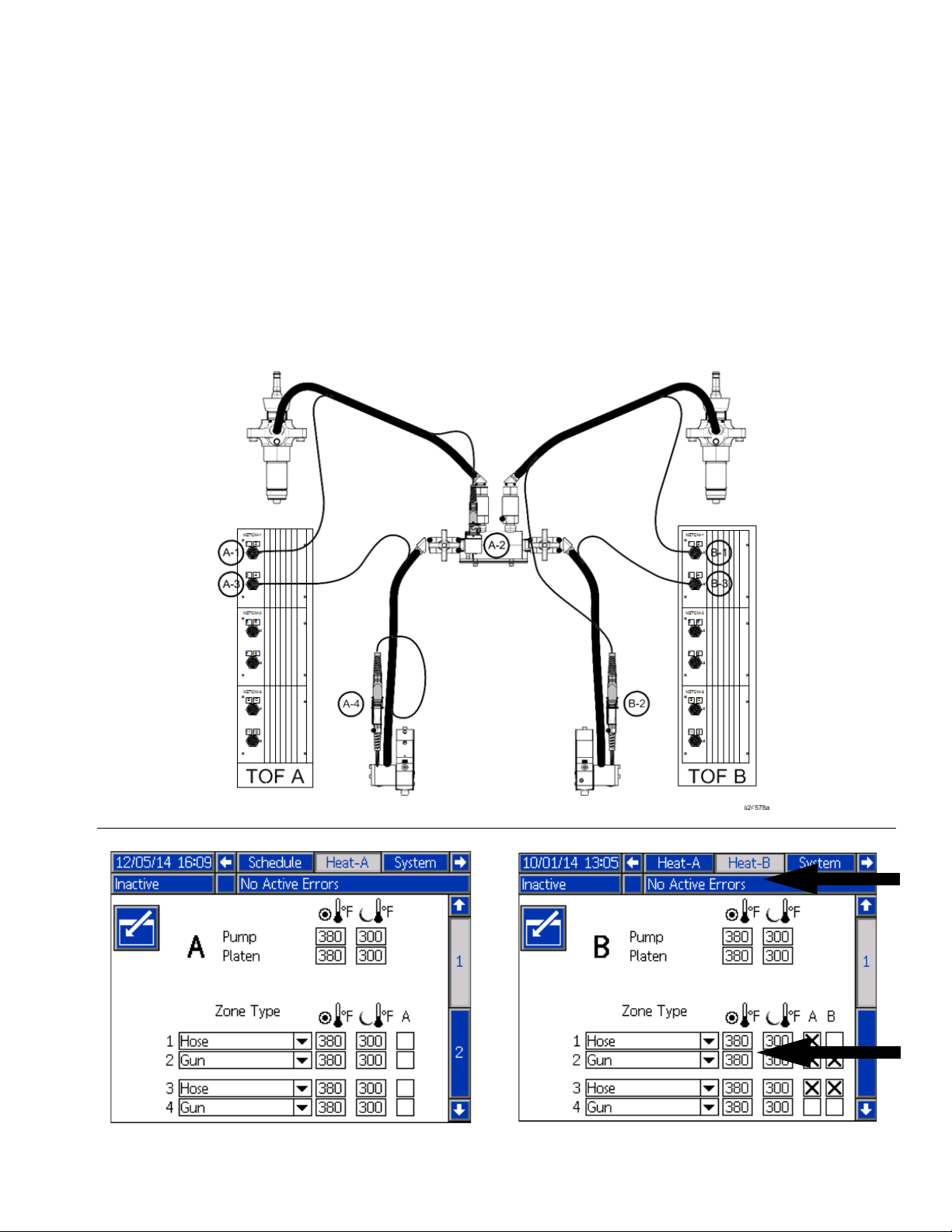
Connect Multiple Devices
If your application requires multiple fluid control devices:
• Connect heated hose electrical connections to the
Electrical Enclosure. Remove from shipping box to
connect heated hoses to the Electrical Enclosure.
For additional cables, heated hose, and fluid control
devices, see Accessories and Kits, page 92.
• Connect fluid control devices to a heated hose or
the Electrical Enclosure. Use accessories if neces-
sary.
• Setup all heat zones on Heat-A and Heat-B
screens.
Example: Heated zones used to connect a primary and
secondary system to a manifold and two guns. A-#
zones are on the Heat-A screen and B-# zones are on
the Heat-B screen.
FIG. 11
334130T 19
Page 20
Setup
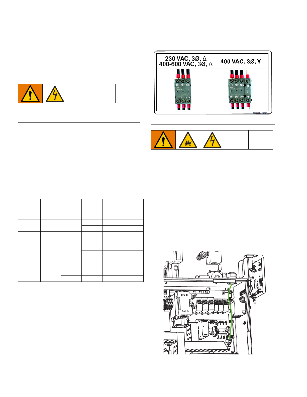
Connect Power
The Electrical Control Panel comes already attached
and wired to the Ram, however before the supply unit
becomes functional you must connect the Electrical
Control Panel to a power source.
All electrical wiring must be done by a qualified electrician and comply with all local codes and regula-
tions.
NOTE: Required voltage and amperage is noted on the
control panel label. Before running power to the unit,
make sure the plant electrical service meets the
machine’s electrical requirements. Branch circuit protec-
tion shall be provided by the end user.
Use copper conductors rated 600 volts minimum and
167°F (75°C) minimum only. Torque to 55 in-lb (6.2
N•m).
Table 2 Electrical Requirements
Electrical
Panel
Voltage Hz Phase Platen
230 V 50/60 3 EF, ES 90 3 AWG
EM 100 3 AWG
400 V/N 50/60 3 EF, ES 45 8 AWG
EM 50 8 AWG
400 V 50/60 3 EF, ES 45 8 AWG
EM 50 8 AWG
480 V 50/60 3 EF, ES 45 8 AWG
EM 50 8 AWG
600 V 50/60 3 EF, ES 50 8 AWG
3EM508 AWG
Full
Load
Amps AWG
FIG. 12
To reduce the risk of fire, explosion, or electric shock,
the resistance between the supply unit components
and true earth ground must be less than 0.25 ohms.
3. Connect the ground wire to the ground lug. Have a
qualified electrician check the resistance between
each Therm-O-Flow system ground and the true
earth ground. The resistance must be less than 0.1
ohms. If the resistance is greater than 0.1 ohms, a
different ground site may be required. Do not oper-
ate the system until the problem is corrected.
NOTE: Use a meter that is capable of measuring resis-
tance at this level.
EF Standard Finned Bottom
EM Mega-Flo
ES Smooth Bottom
1. Locate the opening in the control panel’s top hous-
ing for the conduit that will enclose the wire from the
facility’s power source. The hole will accept a cord
diameter range of 0.7–1.2 in (17–30 mm).
2. Thread the wire from the power source into the con-
trol panel housing, and then connect the power
source wires to the appropriate terminals on the
DISCONNECT switch.
20 334130T
Page 21
Setup
AC
SC
SS
Grounding
Ground the unit as instructed here and in the compo-
nent manuals.
The equipment must be grounded to reduce the risk
of static sparking and electric shock. Electric or static
sparking can cause fumes to ignite or explode.
Improper grounding can cause electric shock.
Grounding provides and escape path for the electric
current.
System: ground through ground lug in Electrical Enclo-
sure. See Connect Power, page 20.
Air and Fluid Hoses: use only electrically conductive
hoses.
Air compressor: follow manufacturer’s recommenda-
tions.
Spray gun / Dispense valve: ground through connec-
tion to a properly grounded fluid hose and Pump.
Material drums: follow local code. Use only metal
drums placed on a grounded surface. Do not place the
drum on a nonconductive surface, such as paper or
cardboard, which interrupts the grounding continuity
To maintain grounding continuity when flushing or
relieving pressure: follow instructions in your separate
gun manual for instructions on how to safely ground
your gun while flushing.
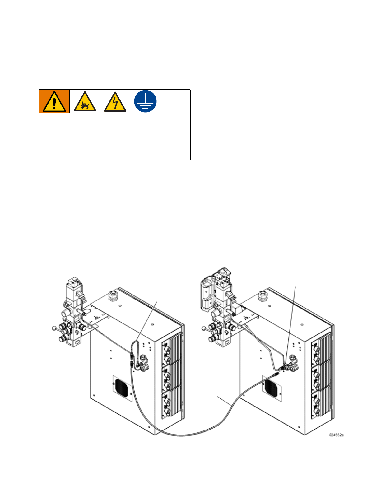
Connect Secondary System
A secondary system is a Therm-O-Flow supply system
that connects to the primary Therm-O-Flow system, with
the ADM. See Models, page 7 for secondary system
model numbers.
1. Connect adapter cable (AC) and communication
cable (SC) to the secondary Electrical Enclosure
and rout to splitter (SS) installed on the primary sys-
tem.
2. To enable a secondary system, select “Enable Tan-
dem System” on the System 1 screen. See Select
ADM Settings, page 24.
FIG. 13
334130T 21
Page 22
Setup
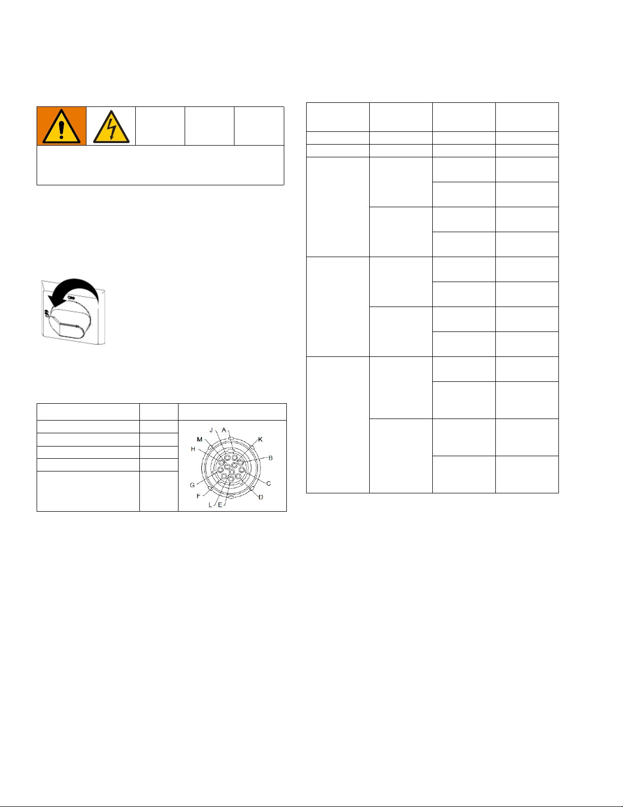
Check Sensor Resistance
To reduce risk of injury or damage to equipment, con-
duct these electrical checks with the Main Power
Switch OFF.
The package includes up to twelve heat sensors and
controllers for each of the heated zones. To check sen-
sor resistance:
1. Turn Main Power Switch OFF.
2. Wait for components to cool down to ambient room
temperature 63°-77°F (17°-25°C). Check electrical
resistance for the components.
MZLP Pins TOF Hose
First Heat Zone A, J
Second Heat Zone C, D
First RTD G, K
Second RTD M, K
Earth Ground B
Table 3 RTD Sensors
MZLP MZLP Plug Component
Ram Plate 100 +/- 2
Fluid Pump 100 +/- 2
Heated
1, 2
1
3, 4
5, 6
2
7, 8
9, 10
3
11, 12
Accessory 1
Heated
Accessory 2
Heated
Accessory 3
Heated
Accessory 4
Heated
Accessory 5
Heated
Accessory 6
Heated
Accessory 7
Heated
Accessory 8
Heated
Accessory 9
Heated
Accessory 10100 +/- 2
Heated
Accessory 11100 +/- 2
Heated
Accessory 12100 +/- 2
RTD Range
(Ohms)
100 +/- 2
100 +/- 2
100 +/- 2
100 +/- 2
100 +/- 2
100 +/- 2
100 +/- 2
100 +/- 2
100 +/- 2
3. Replace any parts whose resistance readings do
not comply with the ranges listed in the RTD Sen-
sors chart below.
22 334130T
Page 23
Setup
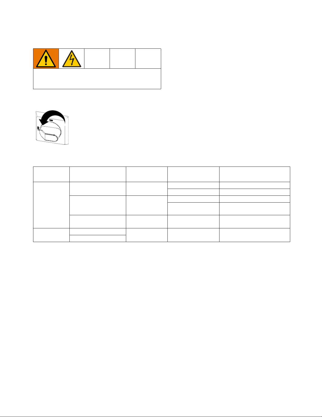
Check Heater Resistance
To reduce risk of injury or damage to equipment, con-
duct these electrical checks with the Main Power
Switch OFF.
1. Turn Main Power Switch OFF. 2. Make electrical resistance checks for the compo-
nents.
3. Replace any parts whose resistance readings do
not comply with the ranges listed in tables.
NOTE: Check resistance at ambient room temperature
63°-77°F (17°-25°C).
Table 4 Heaters
Component
Platen
Pump
Resistance Across
Terminals
AD to BE, BE to CF,
CF to AD
A to B, B to C, C to D,
D to E, E to F and F to A380 - 600V
Any terminal to Ground
2610 to 2620
T1/B1 to T3/B3
Unit Input
Voltage
220 - 240V
All voltage ver-
sions
All voltage ver-
sions
Platen or Pump
Module Resistance Values
24V633 5.25 to 4.35 Ohms
24V634 & 24V635 6.36 to 4.8 Ohms
24V633 12.0 to 14.5 Ohms
24V634 & 24V635 13.5 to 18 Ohms
All Greater than 100,000 Ohms
All 43.2 to 53 Ohms
334130T 23
Page 24
Setup
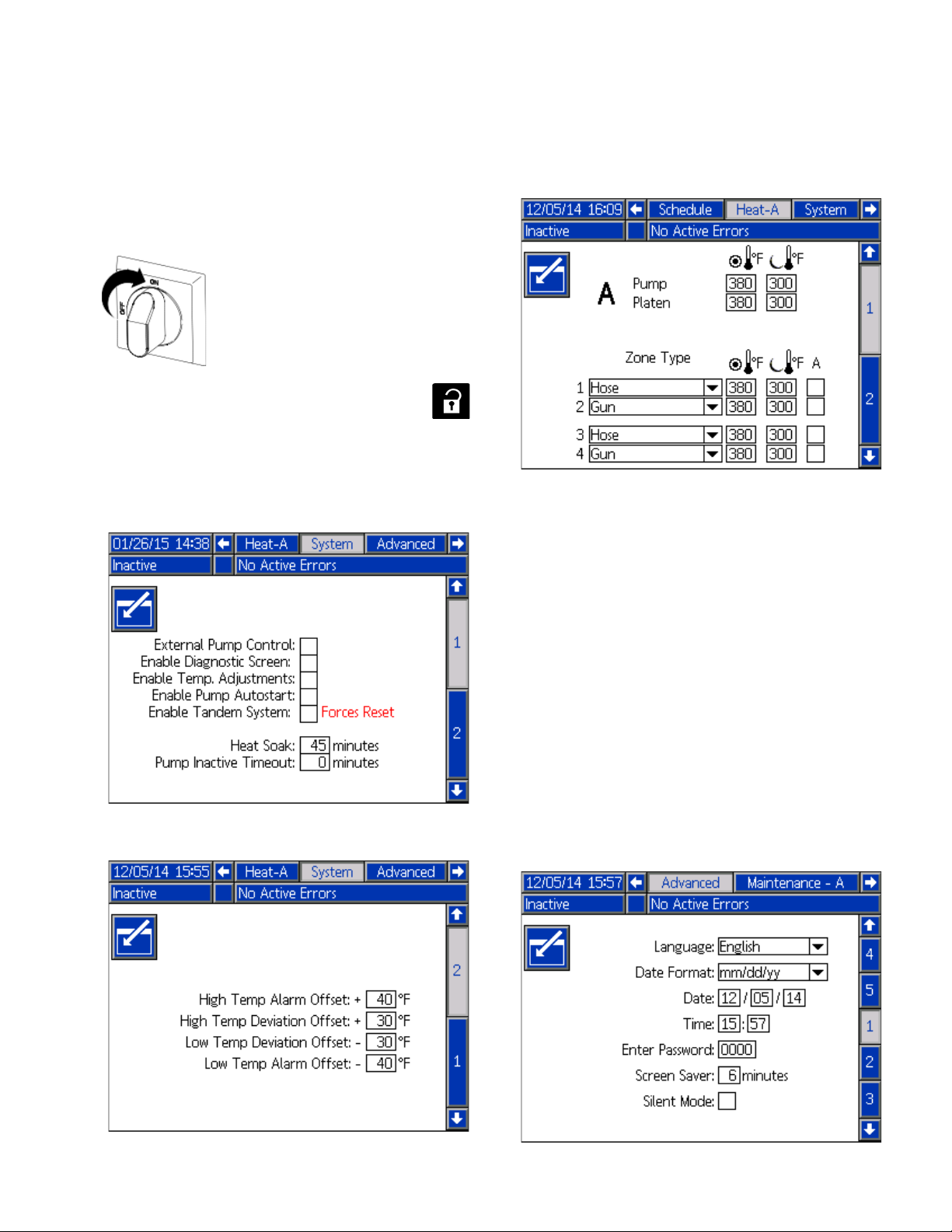
Select ADM Settings
NOTE: See Appendix A - ADM, page 100 for detailed
ADM information, including general operation.
1. Turn Main Power Switch ON.
2. When the ADM is finished starting up, press
to switch from the Operation screens to the Setup
screens. Use the arrows to navigate between
screens.
3. Check system settings on the System 1 screen.
5. Set primary system setpoint and setback tempera-
tures for the Pump, Platen, and heat zones on the
Heat-A-screens.
NOTE: Setback temperatures must be at least 20°F
(10°C) lower than the setpoint temperatures.
NOTE: To ensure accurate hose temperatures, be sure
all heated hoses have their “zone type” set to “Hose.”
Hoses are only present on odd zone numbers: 1, 3, 5, 7,
9, or 11.
4. Set alarm levels on the System 2 screen.
a. Select the appropriate “Zone Type” for all
installed zones.
b. Check the “A” and “B” boxes according to which
systems needs to use the heated accessory.
6. If a secondary system is used, set temperatures on
the Heat-B-screens.
7. Set the system date and time on the Advanced 1
screen.
24 334130T
Page 25
Setup
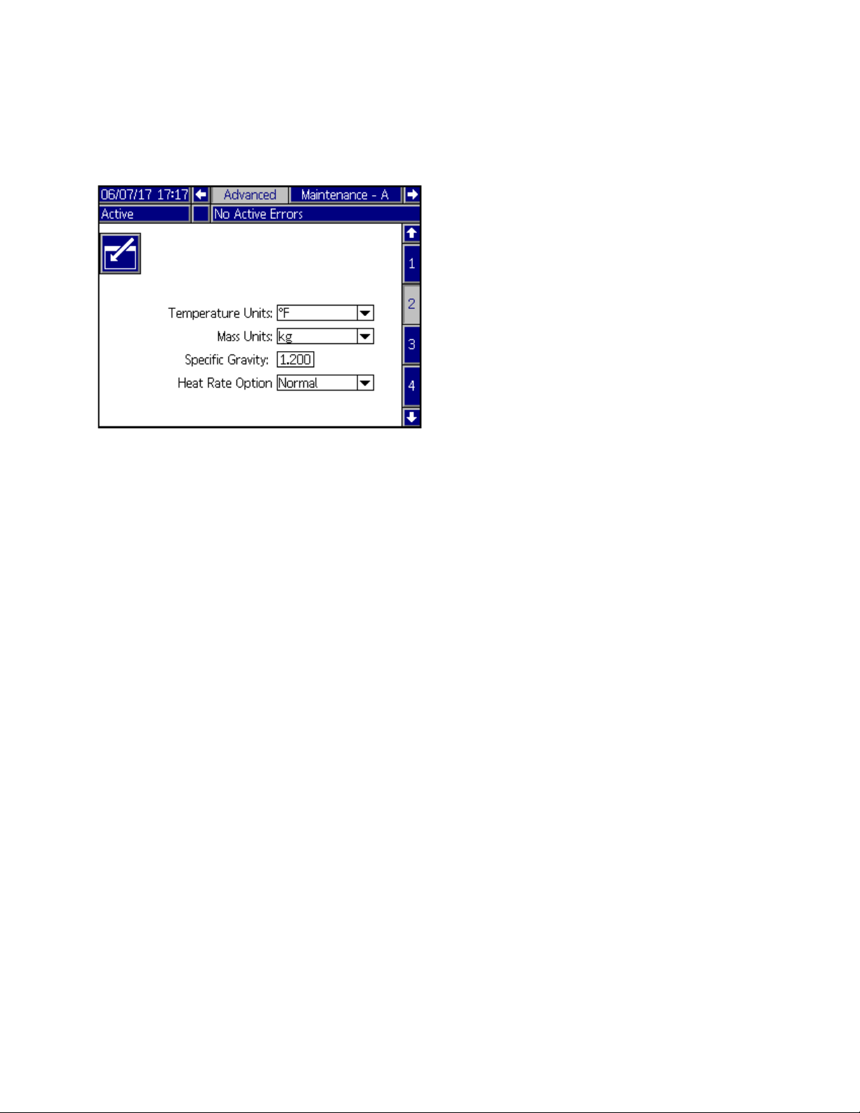
8. Set the temperature and mass units on the
Advanced 2 screen. Set the specific gravity of the
material for Material Tracking functionality.
NOTE: If the Specific Gravity is set to zero, the Home
screen will display a cycle counter instead of grams or
pounds.
9. To setup the optional Schedule function, see
Schedule, page 37. The schedule function allows
the system to automatically enable and disable
heating and setback at specified times.
10. Optional: Set any remaining settings in the Setup
screens before using the system. These are not
required for system operation, but include useful
functions. See Appendix A - ADM, page 100 for
detailed information about each setup item.
334130T 25
Page 26

Setup
Connect PLC (Hard Wired Interface Version)
A PLC can control and monitor all items shown in the
Customer Digital Inputs and Outputs shown on the Diag-
nostics screen. See Appendix A - ADM, page 100.
When the PLC has control of the system:
• Functionality is restricted from the ADM
• Automatic crossover is disabled. Rely on the PLC
and machine state indicators to know when to cross
over using the I/O.
Table 5 Customer Input
Signal No. Unit A Description
1 Heat On Request Turn on the Heat
2 Setback Request Put the Unit in Set-
back
3 Pump On Request Turn on the Pump
4PLC Control
Request (input
applies to primary
unit A only)
Table 6 Customer Output
Control the primary
and secondary TOF
systems from the
PLC instead of the
ADM
Table 7 Output Error States
Error State
Bit High Error State Bit Low
0 0 Machine is good, no
errors are present
0 1 Active Unit Drum
Low
1 0 Active Unit Drum
Empty
1 1 Alarm Present in
System
Table 8 Output Run States
Run State
Bit High Run State Bit Low
0 0 Pump Off/ Heat Off
0 1 Pump Off/ Heat On
1 0 Pump Off/ Heat At
Temp
1 1 Pump On/ Heat At
Temp
NOTE: All outputs are normally open when power is off.
For error (alarm) output, the contacts close when an
alarm occurs. For all others, contacts close.
NOTE: The TOF system ships with two screw terminal
connectors that plug into MZLP connectors H1 and H2.
Connectors are located in a bag on the inside of the
Electrical Enclosure. To replace the connectors, order
kit 24P176.
Signal No. Unit A or B Description
1 Run State Bit Low See Run State
Chart
2 Run State Bit High See Run State
Chart
3 Error State Bit Low See Error State
Chart
4 Error State Bit High See Error State
Chart
26 334130T
1. Turn Main Power Switch OFF.
2. Open the Electrical Enclosure door.
3. Route I/O cables through strain relief.
4. Remove power from the PLC.
5. Connect the PLC to connectors H1 and H2.
Page 27
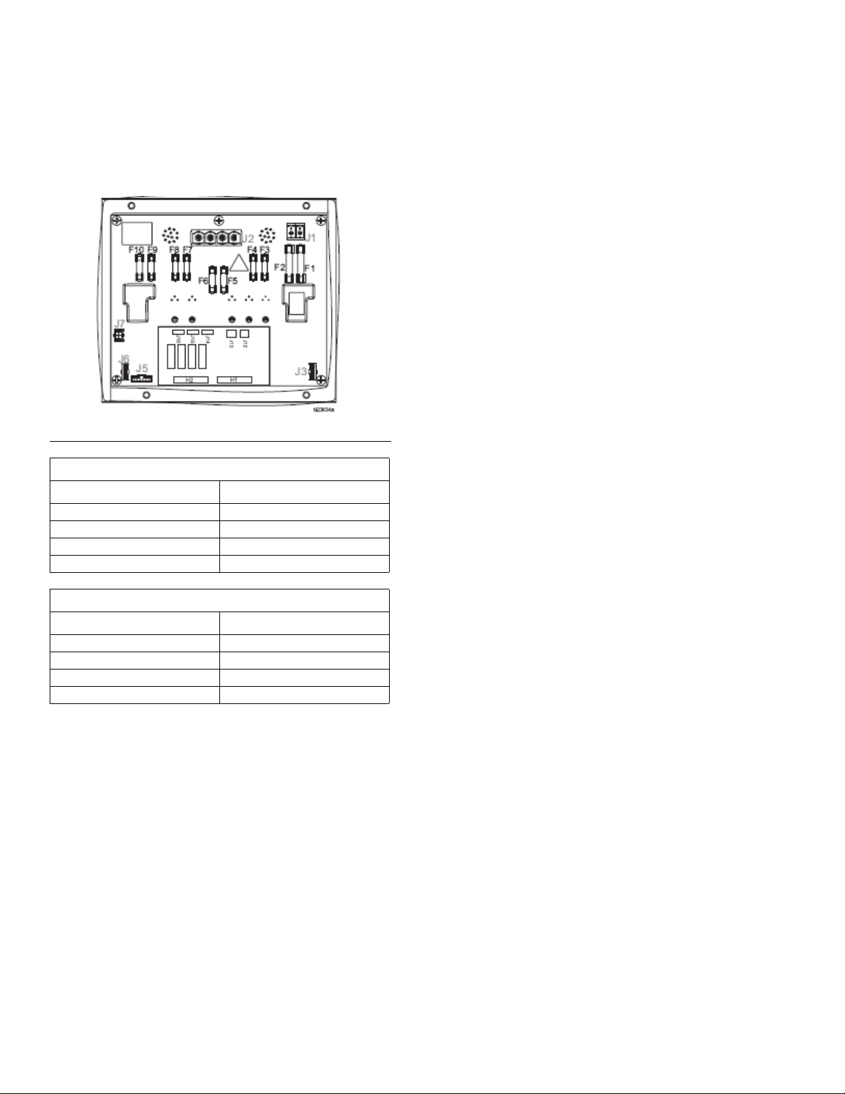
NOTE: Each connector has four signals. The MZLP
board specifies the input range for each signal. See the
following table for pin assignments.
FIG. 14
Setup
H1 Customer Input
Signal Pin
11,2
23,4
35,6
47,8
H2 Customer Output
Signal Pin
11,2
23,4
35,6
47,8
Inputs: High: 10–30 VDC, Low: 0–5 VDC. Inputs func-
tion without concern for polarity. Applying “high” voltage
will turn the heaters on and enable setback. Removing
voltage will turn the heaters off and disable setback.
Outputs: 0–250 VAC, 0–30 VDC, 2A Maximum.
334130T 27
Page 28
Setup
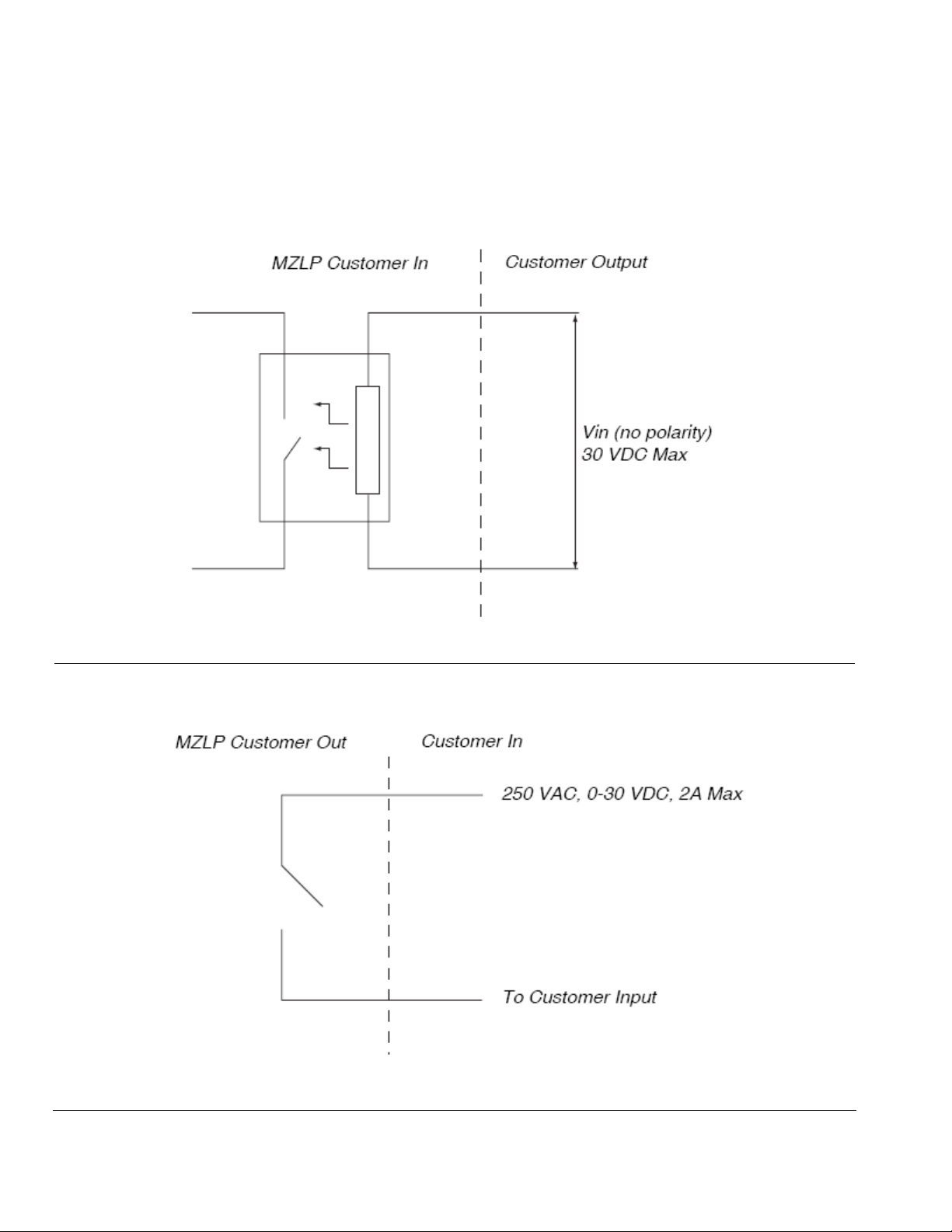
PLC Connections Block Diagrams
The following block diagrams show how to connect customer inputs and outputs to the MZLP. For convenience, each
system ships with connector kit 24P176. If a connector is lost or damaged, order kit 24P176 for replacements.
FIG. 15: Customer Input
FIG. 16: Customer Output
28 334130T
Page 29

Operation
1. Turn the Main Power Switch ON. The Graco logo
will display until communication and initialization is
complete.
Operation
NOTICE
Use fluids that are chemically compatible with the
equipment wetted parts. See Technical Specifica-
tions in all of the equipment manuals.
1. Select the material for the initial material load.
2. Verify whether the factory-test oil and the initial
material load are compatible:
a. If the two substances are compatible omit the
remaining steps in this procedure and refer to
Load Material, page 30.
b. If the two substances are incompatible perform
the remaining steps in this procedure to flush
the system.
2. Press the button. Verify the machine is in
“Warm Up” state, and that the temperatures are
increasing. Allow the system to reach the “Ready”
state before pumping. The Pump will automatically
turn on, if autostart is enabled in setup screens,
when all the heat zones reach their setpoint tem-
perature.
Purge System
NOTICE
Purge the system before initial use and when chemi-
cals are changed to prevent material contamination,
which may cause the material to fail or perform poorly.
The system was factory- tested using a light soluble
oil, a soybean oil, or some other oil as tagged. Flush
the system to avoid contaminating the material that
has been designated for initial material loading.
3. Select a drum of material that can eliminate the fac-
tory-test oil from the system. If necessary, check
with Graco or the material supplier for a recom-
mended solvent.
4. Before purging be sure the entire system and waste
drum are properly grounded. See Grounding, page
21.
5. Turn all heat zones’ setpoint temperature to the
material manufacturer’s recommended dispense
temperature, or a minimum of 100°F (37°C) mini-
mum.
NOTE: Remove any dispense valve orifices before
purging. Reinstall after purging has been completed.
6. Purge the material through the system for approxi-
mately 1 to 2 minutes.
7. Remove the drum if purge material was used. See
Change Drums, page 38.
334130T 29
Page 30
Operation
CA
CD
CC
Load Material
NOTICE
To prevent damage to Platen wipers, do not use a
drum of material that has been dented or damaged. An
empty drum clamp can interfere with up and down
operation of the Ram. When raising the Ram, make
sure the drum clamp stays clear of the Platen.
NOTE: Before loading material, make sure there is a
minimum overhead clearance of 110 in. (280 cm) and all
air regulators are backed off to their full counterclock-
wise position.
1. Open the Main Air Slider Valve (CA).
4. Fill displacement pump wet cup 2/3 full with Graco
Throat Seal Liquid (TSL™) for Butyl and PSA mate-
rials.
NOTE: Use IsoGuard Select
for PUR or reactive Polyurethane material. IGS is
designed to dissolve and suspend the Polyurethane
materials. IGS will solidify after a period of time and
should be replaced once the solidified lube does not
return to liquid form after heating.
FIG. 18: Wetcup
®
(IGS) (part no. 24F516)
2. Set Ram Director Valve (CC) to UP and slowly turn
the Ram Up Regulator (CD) clockwise until the
Platen (G) begins to rise.
5. Open drum, remove any packing material, and
inspect material for any contamination.
6. Slide the drum between the drum centering guides
and against the stops at the back of the Ram base-
plate.
FIG. 17: Raise the Platen
3. Apply a thin coating of high temperature grease
lubricant (part no. 115982) to the Platen drum seals.
30 334130T
FIG. 19: Drum Placement
Page 31

Operation
R
CC
CB
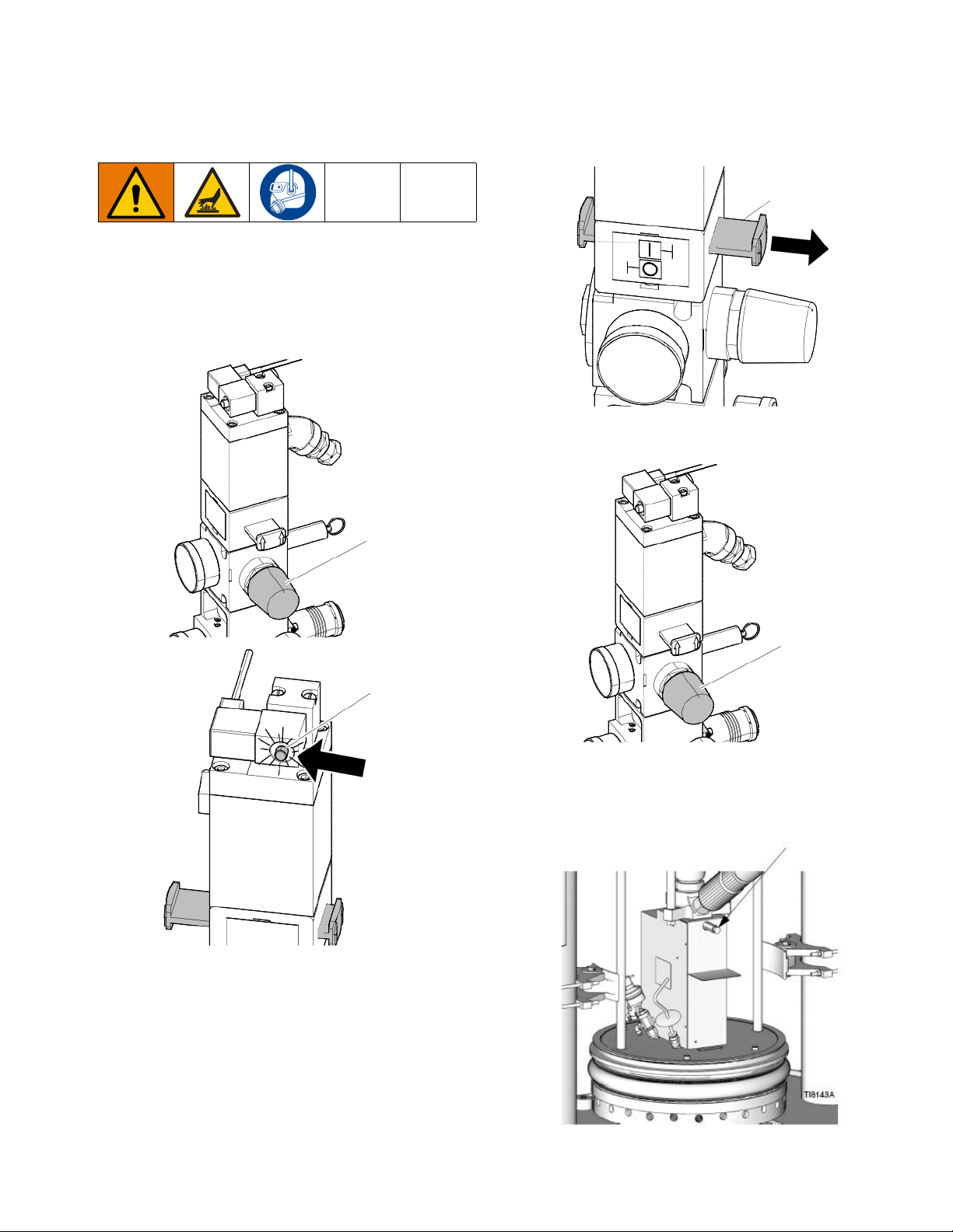
7. Remove the Ram Plate Bleed Stick (R).
FIG. 20: Platen Bleed Handle
8. Set Ram Director Valve (CC) to down.
Heat Up System
To reduce the risk of bursting a hose, never pressur-
ize a hot melt system before turning on the heat. The
air will be locked from the Air Motor until all temperature zones are within a preset window of the tempera-
ture setpoints.
Keep the dispense valve open over a waste container
while the system is heating up and also when cooling
down. This will prevent a pressure build-up caused by
fluids or gases expanding from the heat.
NOTE: Operate at the lowest temperature and pressure
necessary for your application.
1. Turn the Main Power Switch on the Electrical Con-
trol Panel door to the ON position.
2. Press the button. The zones begin to heat
(provided they are enabled). Press if the
zones do not begin to heat. Display status bar reads
Warm Up. When temperature reaches setpoint, the
display status bar reads Heat Soak. When heat is
on, the status will display in the status bar. See
Advanced Display Module (ADM), page 12, for
operation mode descriptions.
NOTE: The air will be locked from the Air Motor until all
FIG. 21: Lower the Platen
9. Slowly turn the Ram Down Air Regulator (CB) clock-
wise to approximately 5–10 psi (34–69 kpa, 0.3–0.7
bar). The Platen will begin to lower into the drum.
10. After the Platen seals enter the material drum,
adjust the Ram Down Air Regulator (CB) to 30–50
psi (207–345 kPa, 2.1–3.4 bar).
11. When the Ram stops, reinsert the Ram Plate Bleed
Stick (R) and hand tighten.
temperature zones are within a preset window of the
temperature setpoints, allowing the system to heat fully
and complete the material heat soak period.
334130T 31
Page 32
Operation
CK
CN
CM
CK
Z
Prime Pump
1. Ensure that the system has completed the heat
soak cycle. The display status bar should read
Active.
2. Adjust the Air Motor Air Regulator (CK) to 0 psi.
3. Adjust the Air Motor Slider Valve (CM) to the open
position.
4. Adjust the Air Motor Air Regulator (CK) to approxi-
mately 20 psi (138 kPa, 1.38 bar).
5. Place a waste container under the bleed stem (Z).
Using an adjustable wrench, open the bleed stem
counterclockwise 1/3 -1/2 turn.
32 334130T
Page 33
Operation
CA
6. If a new drum was installed and the unit is equipped
with proximity sensors, press the Pump Ready but-
ton . Press the pause button on material
tracking.
7. Adjust the Air Motor Air Regulator (CK) up by 5 psi
(34 kPa, 0.3 bar). Never adjust the regulator by
more than 5 psi (34 kPa, 0.3 bar) increments. Make
sure the Pump begins to cycle and heated material
flows from the bleed stem (Z) after several cycles of
the Pump.
8. Prime the Pump until it moves smoothly in both
directions with no air popping or erratic movement
and close the bleed stem (Z).
For Tandem Operation
Complete steps 1-5 on page 32 for the inactive unit.
Note that the heat will remain on for the inactive unit
until the system is turned off.
6. If a new drum has been installed in the inactive unit,
press the Pump Ready button on the inactive
unit. The light on the solenoid of the inactive unit
should be on (CN).
7. Adjust the Air Motor Air Regulator (CK) up by 5 psi
(34 kPa, 0.3 bar). Never adjust the regulator by
more than 5 psi (34 kPa, 0.3 bar) increments. Make
sure the Pump begins to cycle and heated material
flows from the bleed stem (Z) after several cycles of
the Pump.
8. Prime the Pump until it moves smoothly in both
directions with no air popping or erratic movement
and close the bleed stem (Z).
9. Press the Pump Ready button for the inactive
unit.
9. Press the Play button on the home screen to
enable material tracking and press the Pump Ready
button.
334130T 33
Page 34
Operation
CA
Z
Prime System
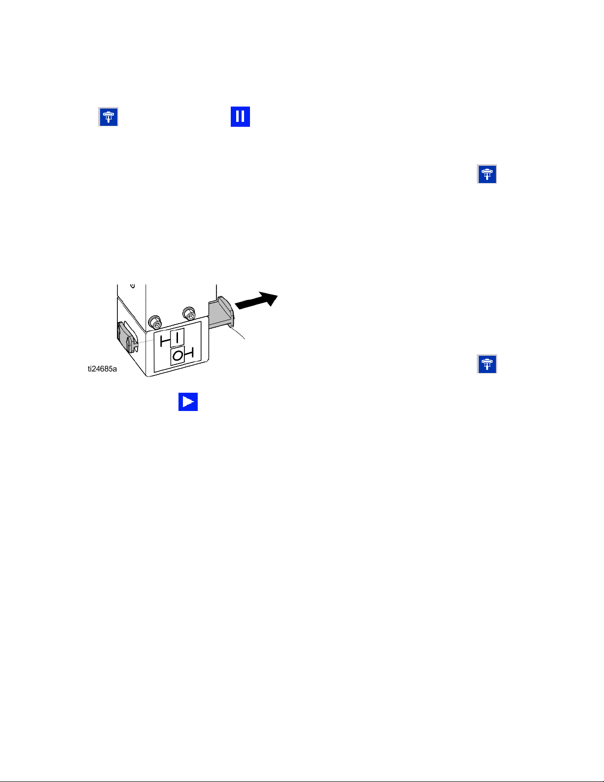
1. Close the Main Air Slider Valve (CA).
2. If using a manual gun, lock the dispense valve trig-
ger open by pulling and securing the trigger using
the trigger retainer (Z).
7. Close the Main Air Slider Valve (CA) and release the
trigger lock.
8. Engage the trigger lock.
FIG. 22: Trigger Lock Engaged
9. Press to engage material tracking.
10. Turn the Air Motor regulator to operating pressure.
3. Place the dispense valve over a waste container.
4. Press the pause material tracking button on
home screen.
5. Slowly open the Main Air Slider Valve (CA).
6. Prime the system until a smooth flow of material dis-
penses from each dispense valve.
NOTE: On initial system startup, the Pump will cycle
until the hoses are filled. If a new drum was placed on
the frame, the Pump will cycle until all air has been
removed.
NOTE: The amount of time before the Pump is automatically placed in setback is determined by the Pump Inac-
tivity Timeout, located on System Setup Screen 1. See
Setup Screens, page 104.
Setback Mode
Set the ADM to setback mode if the system will only be
inactive for a few hours. This will reduce the time the
system needs to return to setpoint temperatures.
1. Press to enter Setback Mode.
NOTE: The amount of time before the Pump is automatically placed in setback is determined by the Pump Inac-
tivity Timeout, located on System Setup Screen 1. See
Setup Screens, page 104.
34 334130T
Page 35
Operation
CA
CC
Pressure Relief Procedure
Follow the Pressure Relief Procedure When-
ever you see this symbol.
This equipment stays pressurized until pressure is
manually relieved. To help prevent serious injury from
pressurized fluid, such as skin injection, splashing
fluid and moving parts, follow the Pressure Relief
Procedure when you stop spraying and before clean-
ing, checking, or servicing equipment.
NOTE: If using a different dispense applicator, see the
applicator manual for pressure relief instructions.
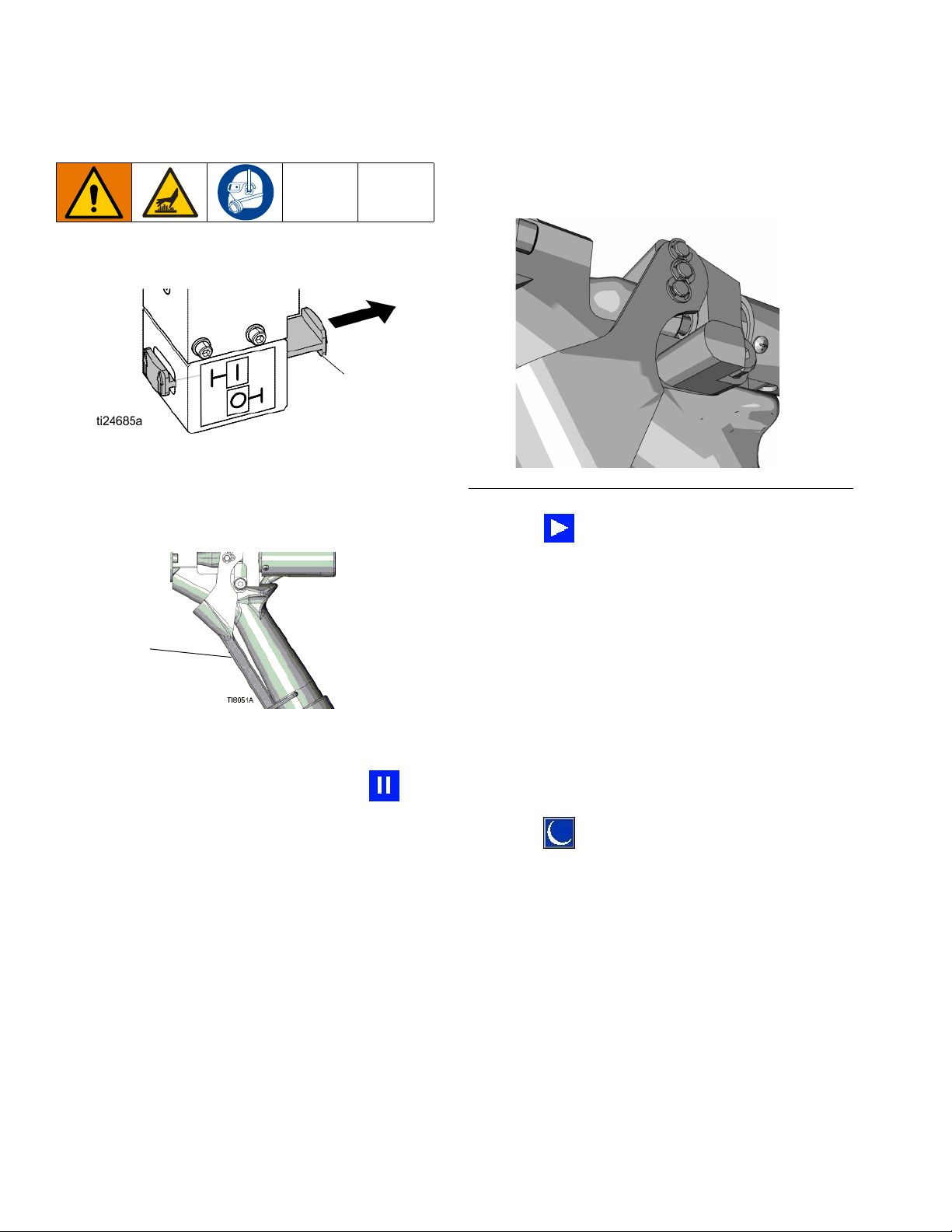
1. Engage the trigger lock.
3. Set the Ram Director Valve (CC) to the neutral posi-
tion.
4. Disengage the trigger lock.
FIG. 24: Disengaged
FIG. 23: Engaged
2. Close the system Main Air Slider Valve (CA).
334130T 35
5. Hold a metal part of the gun firmly to a grounded
metal pail. Trigger the gun to relieve pressure.
6. Engage the trigger lock.
7. Open all fluid drain valves in the system, having a
waste container ready to catch drainage. Leave
drain valve(s) open until you are ready to dispense
again.
8. If you suspect the tip or hose is clogged or that pres-
sure has not been fully relieved after following the
steps above, VERY SLOWLY loosen hose end coupling to relieve pressure gradually, then loosen com-
pletely. Clear hose or tip obstruction.
Page 36
Operation
System Shutdown
NOTE: If work needs to be performed on the Ram por-
tion, perform the following additional steps to relieve any
trapped air in the inactive portion of the Ram.
9. Validate that the Heated Pump is fully supported
and is resting on the bottom plate.
Stop Controls
Normal Stop Control
To stop all electrical and most pneumatic processes,
press the System Shutdown button located on the
ADM.
10. Toggle the Ram Director Valve up and down to
relieve any trapped air.
All electrical operations will be shut down and the air
pressure to the Air Motor will be immediately relieved,
which will stop the movement of the Heated Pump.
Electrical components located in the main control box
will remain energized, but all operations will stop until
the system Enable/Disable button has been
pressed.
The Ram Director Valve will remain operable.
Air Motor and Heated Pump Stop
To stop only the Air Motor and Heated Pump, close the
Air Motor Slider Valve (CM). This is the preferred
method while changing drums.
36 334130T
Page 37
Operation
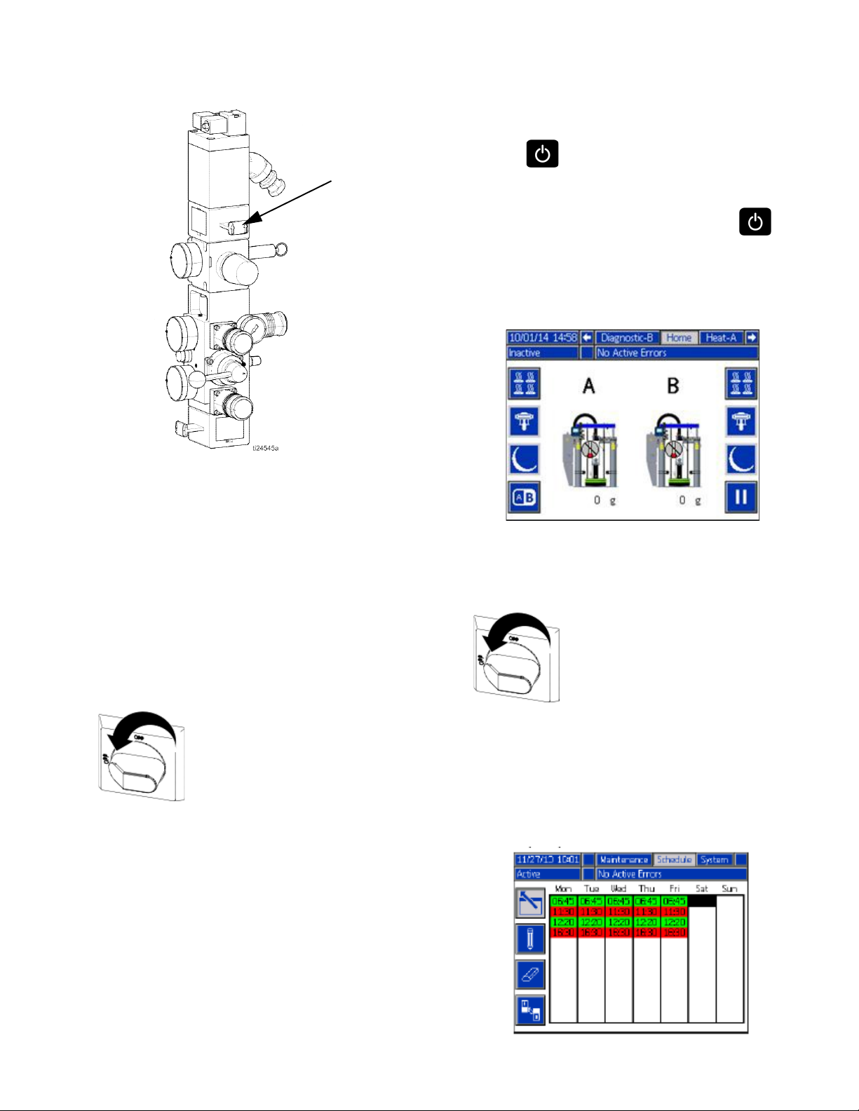
CM
Shutdown
1. Press to disable the heaters and Pump. The
screen will say “Inactive”. If using the Schedule
function, the heaters and Pump will be disabled
automatically at the set time. Only press to
disable the heating system before the set time. If the
heaters were manually disabled, the Schedule func-
tion will automatically enable them at the next set
time.
Air pressure to the Air Motor will be immediately
relieved, which will stop movement of the Heated Pump
but allow the heater to remain operable.
The Ram Director Valve will also remain operable.
The Air Motor Slider Valve can be locked in the closed
position.
Total System Shutdown
To stop all electrical and most pneumatic processes,
turn the Main Power Switch OFF.
This will remove all electrical power to the system past
the Main Power Switch.
Air pressure to the Air Motor will be relieved, which will
stop movement of the Heated Pump.
NOTE: Do not perform step 2 if using the Schedule
function. Leave the power on.
2. Turn the Main Power Switch OFF.
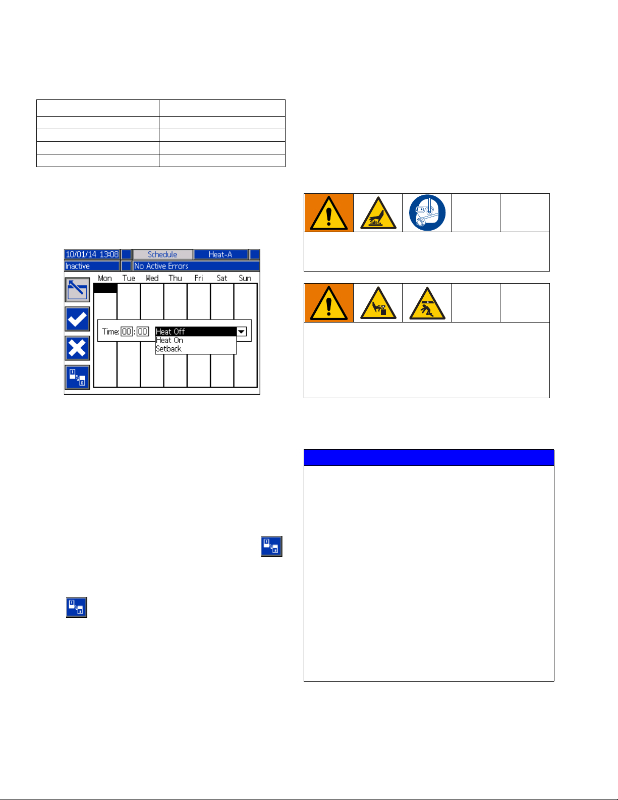
Schedule
The Schedule function allows the user to specify times
when the system will automatically turn on and off the
heaters and Pump.
The Ram Director Valve will remain operable.
The Main Power Switch can be locked in the open posi-
tion.
334130T 37
Page 38
Operation
Table 9 Schedule Screen Color Identification
Color Description
Green System on
Yellow Setback
Red System off
Gray Disabled
Set Schedule Times
Times are set using a 24-hour clock. Several on and off
times can be set each day.
Use the Schedule Function
At the end of the work day leave the Main Power Switch
ON. The Schedule function will automatically enable
and disable the heaters and Pump at the specified
times.
Change Drums
To prevent serious burns from dripping material,
never reach under the Heated Platen after the Platen
is out of the drum.
Moving parts can pinch or amputate fingers, or can
crush feet. When the Pump is running, and when rais-
ing or lowering the Ram, keep fingers and hands
away from the Pump intake, Platen, and lip of the
drum. When lowering the Platen to the baseplate,
keep feet away from the Platen.
1. On the Schedule screen (in the Setup screens), set
the ON times for each day of the week
2. Set the off times for each day of the week.
3. Set the setback times for each day of the week.
Enable Schedule Function
The Schedule function is automatically enabled when
values are entered in the Schedule screen. To disable a
scheduled event, navigate to the event and press .
The event will appear gray on the screen when it is dis-
abled. To re-enable an event, navigate to the event and
press .
The event will appear red (system off), yellow (system
setback), or green (system on). If no events are needed,
turn the Main Power Switch OFF to prevent system from
automatically enabling and disabling the heaters.
Perform the following procedure to change the drum on
a fully heated system.
NOTICE
Be sure to reload the empty supply unit with a full
drum of material immediately. Do not raise the Ram
and remove the Platen from the empty drum until you
are ready to immediately install a new drum.
Do not raise the Ram and remove the Platen from
the empty drum unless the supply unit is at full
operating temperature. Drum changes can only be
performed when the system is heated.
An empty drum clamp can interfere with the up and
down operation of the Ram. When raising or lowering
the Ram, make sure the drum clamp stays clear of the
Platen assembly.
Do not use a drum of material that has been dented
or otherwise damaged; damage to the Platen wipers
can result.
38 334130T
Page 39
All systems include Low/Empty Sensors:
CM
CC
CG
• The air will shut off to prevent the Pump from cavita-
tion. If the Light Tower kit is installed, a solid red
light indicates that the pail is empty and ready to
change.
• In a tandem system, a flashing red light means that
both drums are empty and the system has shut-
down.
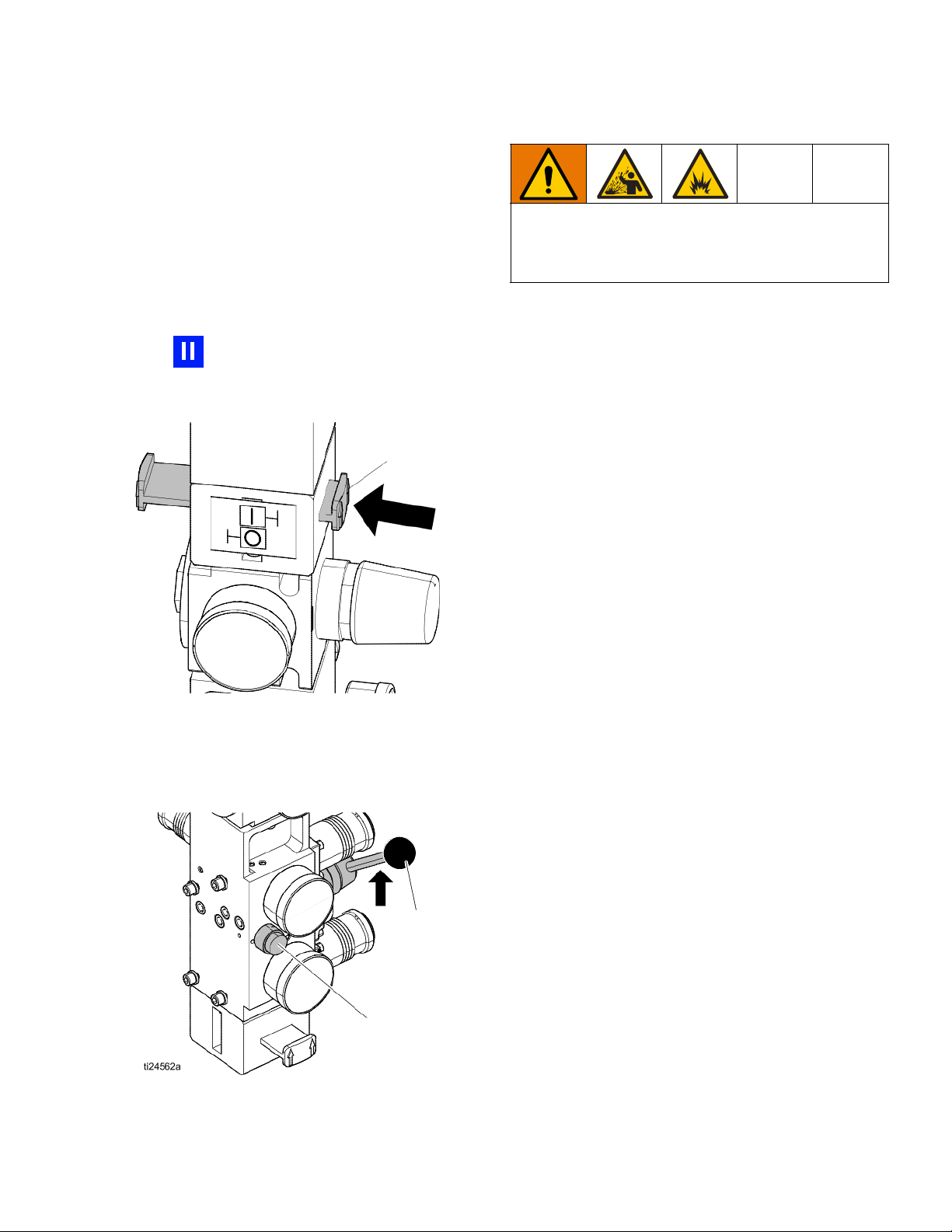
Operation
Excessive air pressure in the material drum could
cause the drum to rupture, causing serious injury. The
Platen must be free to move out of the drum. Never
use drum blowoff air with a damaged drum.
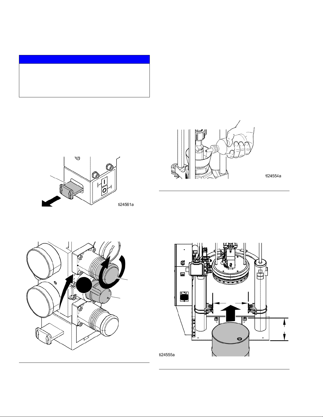
4. Release the blowoff air button and allow the Ram to
rise to its full height.
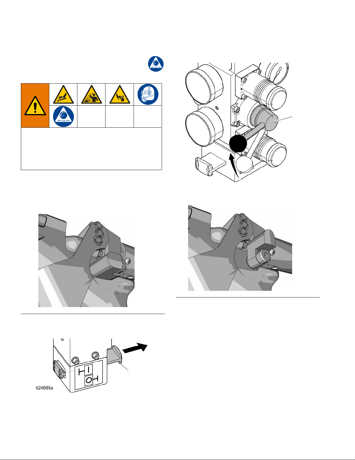
1. Press to stop material tracking.
2. Push in the Air Motor Slider Valve (CM) to stop the
Pump.
3. Set Ram Director Valve (CC) to UP and raise the
Platen (G) and immediately press and hold the
Blowoff Buttons (CG) until the Platen is completely
out of the drum. Use minimum amount of air pres-
sure necessary to push the Platen out of the drum.
5. Remove the empty drum.
6. Inspect Platen and if necessary, remove any
remaining material or material build-up.
7. Follow steps in Load Material, page 30, and Prime
Pump, page 32.
334130T 39
Page 40
Troubleshooting
Troubleshooting
Light Tower (Optional)
Signal Description
Red Light Off If green light is also off, system power may be off or system operating mode is Inactive. If
green is on or flashing, there are no active errors
Red Light On User interaction required — alarm, system is shut down
Red Light Flashing User interaction required — advisory, deviation, or system is in a state that could prohibit
dispensing
Green Light Off System is inactive
Green Light On System is ready to dispense. The heat and Pump are on.
Green Light Flashing System will be ready to dispense in time without user interaction (heat on, Pump off, and
temperature control zones have not reached set point)
40 334130T
Page 41
Troubleshooting
Error Codes
There are three types of errors that can occur. Errors
are indicated on the display as well as by the optional
Light Tower.
Alarms are indicated by . This condition indicates a
parameter critical to the process has reached a level
requiring the system to stop. The alarm needs to be
addressed immediately.
Deviations are indicated by . This condition indicates
a parameter critical to the process has reached a level
requiring attention, but not sufficient enough to stop the
system at this time.
Advisories are indicated by . This condition indicates
a parameter that is not immediately critical to the process. The advisory needs attention to prevent more seri-
ous issues in the future.
To acknowledge the error, press .
The last digit of the error code indicates which system
component the error applies. The “#” (pound) character
indicates the code applies to multiple system compo-
nents.
Code Relates To System
Last Digit “#”
1MZLP 1
2MZLP 2
3MZLP 3
5MZLP 5
6MZLP 6
7MZLP 7
G Gateway (CGM)
H Gateway Heartbeat Loss
VAWB Unit A
WAWB Unit B
X Daughter Board Unit A
Y Daughter Board Unit B
The last digit of the error code indicates which heat zone
the error applies. The “_” (underscore) character indi-
cates the code applies to multiple system components.
Component:
The third digit, or sometimes the last digit of the error
code, indicates which unit the error is active on. The “★”
(star) character indicates the code applies to multiple
system components.
Third or Last Digit “★” Code Relates To:
AUnit A
BUnit B
Code Relates To Heat
Last Digit “_”
1 Zone 1
2 Zone 2
3 Zone 3
4 Zone 4
5 Zone 5
6 Zone 6
7 Zone 7
8 Zone 8
9 Zone 9
A Zone 10
B Zone 11
C Zone 12
DPump
EPlaten
Zone:
334130T 41
Page 42

Troubleshooting
Code Description Type Cause Solution
A3MF
AWB Clean Fan Filter
Alarm
Cooling inlet
Clean inlet screen.
screen is dirty
A4 _
High Current Unit _
Zone _
Alarm
Defective or
shorted to
ground on
Verify accessory is rated for 240 VAC.
Verify heater resistance and check for shorts to
ground. Replace as necessary.
zone
A4C#
High Current Fan
AWB, Unit _
Deviation Fan is drawing
too much cur-
rent
Verify there is not an air obstruction at the
inlet/outlet of enclosure. Verify nothing is
preventing fan rotation. Replace fan if
necessary.
A7 _
A8 _
Unexp. Curr. Unit _
Zone _
No Current Unit _
Zone _
Alarm
Unexpected
current flow to
zone
Alarm No Current
Flow to the
Zone
Replace MZLP.
Faulty accessory heater. Measure resistance to
ground between heater leads.
Check for loose or disconnected wires or
plugs.
Check for blown fuses on MZLP.
Check heater resistance for open circuit.
Check for shorts between heater and ground.
Verify cable is plugged into zones 3-4. Replace
heater if necessary.
A8C
AWB No Fan Current
Alarm Cooling Fan
Verify fan is plugged in. Replace if necessary.
not Working
AM3#
High Current SSR
MZLP _
Alarm
Excessive
current flow in
Check for shorts in harness to SSR. Check
polarity of wiring to SSR. Replace if necessary.
the SSR
AM4#
High Current
Contactor MZLP _
Alarm
Defective or
shorted to
ground on
Check for shorts in the harness to contactor.
Check the polarity to contactor. Replace
contactor if necessary.
MZLP
AM8#
CAC#
No Current Contactor
MZLP _
Comm Error MZLP _
Alarm
Alarm
No Current
Flow to the
Contactor
System not
responding to
ADM.
Ensure harness to MZLP is connected. Ensure
wiring to contactor is secure. Replace contactor
if necessary.
System is not properly loaded with correct Soft-
ware.
Dial not set correct on MZLP. Duplicate MZLP
dial
positions (i.e. 1 to 1, 2 to 2, ect).
Check all CAN connections between the ADM
and missing MZLP.
Check if hardware exists on the network.
Replace MZLP if necessary.
CACX
DB Not Present Unit A
Alarm
Daughter
Board not
responding
Dial not set correct on MZLP 5. Set to 5 on
board with daughter board.
Ensure connections between the ADM and
hardware are secure.
Replace Daughter Board.
42 334130T
Page 43

Code Description Type Cause Solution
CCAG
Comm. Error,
Gateway
Alarm
CGM Module
is no longer
responding
Power removed from Gateway. Restore power.
Rotary switch on Gateway changed to positions
between 2 and 8 (must be in 0, 1, or >8
positions).
CACH
Gateway Heartbeat
Loss
Alarm
Heartbeat
signal was
removed while
PLC was
PLC went off line.
Field Bus connection to CGM was broken.
Restore connection between Field Bus and
CGM.
controlling the
TOF via the
CGM
CACY
DB Not Present Unit B
Alarm
Daughter
Board not
responding
Dial not set correct on MZLP. Set to 4 on board
with daughter board.
Ensure connections between the ADM and
hardware are secure.
Replace Daughter Board.
CACV
AWB not present Unit
A
Alarm
AWB not
responding
Ensure connections between the ADM and
hardware are secure.
If a tandem system, ensure AWB 2 jumper is
installed at startup.
Replace AWB.
CACW
AWB not present Unit
B
Alarm
AWB not
responding
AWB 2 jumper was not in place at start up
Ensure connections between the ADM and
hardware are secure.
Replace AWB.
DA X
Pump Runaway
Detected
Alarm
Pump is trying
to feed
adhesive, no
adhesive to
feed.
Adjust the drum empty level sensor to detect an
empty state.
Ensure the Ram Director Valve is in the down
position and sufficient air is forcing the Ram
down.
Melter at incorrect temperature, too low. Check
setpoint and set to manufactures
recommendation.
Worn or
Inspect Pump seals and replace if necessary
damaged
Pump seals
DE X
Reed Switch Failure
Detected
Alarm Reed switch
failed
Check that sensor cable is plugged into the
daughter board at J16.
Check for loose connection at reed switch.
Ensure reed switch is securely attached to the
Air Motor. Replace if necessary.
Troubleshooting
334130T 43
Page 44

Troubleshooting
Code Description Type Cause Solution
DC X Pump Diving Alarm
Pump is trying
to feed
adhesive, no
adhesive to
feed.
Adjust the drum empty level sensor to detect an
empty state.
Ensure the Ram Director Valve is in the down
position and sufficient air is forcing the Ram
down.
Melter at incorrect temperature, too low. Check
setpoint and set to manufactures
recommendation.
Worn or
Inspect Pump seals and replace if necessary
damaged
Pump seals
L1 X Material Level Sen-
sor Error
Alarm
Machine is
detecting an
empty state
without a low
state
Make sure the empty level sensor is not
covered in material
Verify the low level sensor is plugged into J15
of the daughter board. Verify the low level
sensor is close enough to the metal bar; adjust
if necessary.
Replace sensors.
L2 X Material Level Empty Alarm Material drum
is empty
L3 X Material Level Low Deviation Material level
Replace material container. If more material is
leftover, lower the empty level sensor.
Replace at appropriate time.
is low
MMUX USB Log Full Advisory
USB logs fulls.
Data loss will
Download USB data or disable the USB log
errors on the Advanced screen 3.
occur if not
downloaded.
MN X Pump _ Requires
Maintenance
Advisory
User defined
Pump
Perform Pump maintenance, then reset the
counter on the maintenance setup screen.
maintenance
counter has
run out
Ta★
Over Temperature
Switch
Alarm
An over
temperature
switch has
opened.
Check Heat Rate Option on Advanced Screen
2 to make sure it is set to Normal or Slow. If set
to Fast, the switch will open on the pump or
platen.
If “_” is 9, A, B, or C, make sure jumper
16W035 is installed in J5 on MZLP 5 and
MZLP 7 (for tandem units).
T1 _
Low Temp. Unit _
Zone _
Alarm
Zone
temperature
too low
Reduce flow rate.
Increase temperature of accessory upstream.
Faulty accessory heater measure resistance
between heater leads.
Change Low Temp Alarm Offset.
Replace accessory.
T2 _
Low Temp. Unit _
Zone _
Deviation Zone tem-
perature too
low
Reduce flow rate.
Change Low Temp Deviation Offset.
Add zone (temperature) upstream.
44 334130T
Page 45

Code Description Type Cause Solution
Troubleshooting
T3 _
T4C#
T4M#
T4 _
T6 _
T6C#
T8V_
V1|#
V1M#
V4|#
V6M#
High Temp. Unit _
Zone _
AWB Temperature
Runaway
Transformer
AWB High
Transformer Temp
High Temp. Unit _
Zone _
Sensor Err. Unit _
Zone _
AWB Invalid
Thermistor Reading
No Temp. Rise Unit _
Zone _
Low CAN Voltage,
MZLP _
Low Voltage Line
AWB, Unit _
High CAN Voltage,
MZLP _
Wiring Error Line
MZLP _
Deviation
Alarm
Alarm
Alarm
Alarm
Alarm
Alarm
Alarm
Deviation
Alarm
Alarm
Temperature
reading has
risen too high
Cooling fan not
working or inlet
is blocked/dirty
Transformer
Temperature is
too High
Temperature
reading has
risen too high
Bad RTD
Reading
Transformer
thermistor
temperature is
incorrect
Temperature
reading does
not change.
Bad or
overloaded
power supply
The voltage to
the AWB is
below
threshold
Bad or
overloaded
power supply
Incoming
power is wired
incorrectly
Change High Temp Deviation Offset.
Verify setpoint upstream is not hotter than this
zone’s setpoint.
Ensure inlet and outlets are not obstructed.
Verify fan is plugged in.
Ensure inlet and outlets are not obstructed.
Verify fan is plugged in.
Change High Temp Alarm Offset.
Verify setpoint upstream is not hotter than this
zone’s setpoint.
Check RTD wiring and harness/connector
integrity.
Replace RTD.
Verify thermister is securely connected to J7 of
the AWB. Replace transformer if necessary.
Check fuses on MZLP connected to that Zone.
Check wiring to device.
Check heater resistance on device.
Verify power supply voltage is 24 VDC. If
voltage is low, disconnect the power lines and
re-check voltage reading. If voltage is still low,
replace power supply. If voltage is correct after
disconnecting the power lines.
Connect items one at a time until the voltage
drops to isolate the bad module.
Verify transformer voltage top matches
incoming voltage. Verify incoming voltage is
correct.
Verify power supply voltage is 24 VDC. If
voltage is high, replace power supply unit.
Correct the Wiring.
334130T 45
Page 46

Troubleshooting
Code Description Type Cause Solution
V8M#
V4M#
WJ1
WJ2
WSUX
No Line Voltage
MZLP _
AWB High Line
Voltage
Pump _ Solenoid is
disconnected
Pump _ Solenoid
High Current
Configuration Error
USB
Alarm
Alarm
Alarm
Alarm
Advisory
Incoming line
voltage is less
than 100 VAC.
Incoming
voltage is too
high
Pump is not
turning on
when it should
Solenoid is
drawing too
much current
USB
configuration is
not loaded
Verify transformer has the correct tap selected.
Verify CB-1 or FU-4, FU-5, and FU-6 are not
tripped/blown.
Verify RCD-1 is not tripped.
Measure incoming power with system
unplugged. If line voltage is less than 100 VAC,
contact qualified electrician to correct the low
voltage.
Verify the MZLP is plugged in at J2 and the
AWB is plugged in at J5 or J6.
Check incoming voltage is correct for configu-
ration.
Verify the transformer has the correct tap (400,
480, 600) selected.
Verify harness is plugged into J13 of the
daughter board. Verify it is secured to the
solenoid.
Replace Solenoid.
Inspect for short in harness. Inspect for a
shorted solenoid cable/short to the ground.
Replace solenoid.
Install software.
46 334130T
Page 47

Ram Troubleshooting
Problem Cause Solution
Ram will not raise or lower.
Ram raises or lowers too fast.
Air leaks around cylinder rod.
Fluid squeezes past Platen wipers.
Pump will not prime properly, or
pumps air.
Air pressure will not push Platen out
of drum.
Troubleshooting
Closed main air valve or clogged air
line,
Not enough Ram air pressure. Increase Ram air pressure.
Worn or damaged Ram piston. Replace piston. See instruction man-
Platen not fully up to temperature. Wait for full temperature.
Ram air pressure too high. Decrease Ram air pressure.
Dented drum has stopped Platen. Fix or replace drum.
Ram "up / down" air pressure too
high.
Worn rod seal. Replace o-rings in guide sleeve. See
Ram air pressure too high. Decrease Ram air pressure.
Worn or damaged wipers. Replace wipers.
Closed main air valve or clogged air
line.
Not enough air pressure. Increase air pressure.
Worn or damaged Ram piston. Replace piston. See instruction man-
Ram directional valve closed or
clogged.
Ram directional valve dirty, worn, or
damaged.
Directional valve not in the down
position.
Dented drum has stopped Platen. Fix or replace drum.
Closed main air valve or clogged air
line.
Platen not fully up to temperature. Wait for full temperature.
Not enough blow-off air pressure. Increase blow-off air pressure.
Blow-off valve passage clogged. Clean valve passage.
Dented drum has stopped Platen. Fix or replace drum.
Wipers bonded to drum or drum liner. Lubricate wipers with high tempera-
Open air valve; clear air line.
ual 310523.
Decrease Ram air pressure.
instruction manual 310523.
Open air valve; clear air line.
ual 310523.
Open valve; clear valve or exhaust.
Clean; repair valve.
Position handle in the down position.
Open air valve; clear air line.
ture grease at every drum change.
334130T 47
Page 48

Troubleshooting
Heated Pump Troubleshooting
See Pump manual for additional Pump troubleshooting information.
Problem Cause Solution
Rapid downstroke or upstroke (Pump
cavitation).
Material leaks around Pump outlet.
Material leaks around bleed port.
Pump will not move up and down.
Leak around Pump wet-cup.
Material not heated to proper
temperature.
Air is trapped in Pump.
Downstroke: Dirty or worn Pump
intake valve.
Upstroke: Dirty or worn Pump piston
valve.
Machine is out of material Adjust empty level sensor.
Loose outlet fitting. Tighten outlet fitting.
Loose bleed port fitting. Tighten bleed port fitting.
Problem with Air Motor. See Air Motor Manual.
Foreign object lodged in Pump. Relieve pressure. See Pump Manual.
Platen not fully up to temperature. Wait for full temperature.
Valve to Air Motor is off.
Worn throat seals.
Check and adjust temperature to
proper setpoint. Wait for Pump/Platen
to heat up.
Bleed air from Pump. See Prime
Pump, page 32.
Clean or repair. See Pump Manual.
Clean or repair.
Check gauges and valves to the air
motor.
Replace throat seals. See Servicing
the Throat packings in manual 334127
or 334128.
Air Motor Troubleshooting
See Air Motor manual for additional Air Motor troubleshooting information. See Related Manuals, page 8.
Problem Cause Solution
Air motor will not run.
Air motor stalled.
Air continuously exhausting around
Air Motor shaft.
Air continuously exhausting around
air valve/slide valve.
Air continuously exhausting from
muffler when motor is idle.
Icing on muffler.
Air motor solenoid is off. Wait for heat zones in use to reach
temperature setpoint values.
Damaged main air valve spool or
poppets.
Damaged Air Motor shaft seal. Replace Air Motor shaft seal. See Air
Air valve/slide valve gasket is dam-
aged.
Internal seal damage. Rebuild Air Motor. See Air Motor
Air motor operating at high pressure
or high cycle rate.
Inspect and clean poppets. See Air
Motor Manual.
Rebuild main air valve. See Air Motor
Manual.
Motor Manual.
Replace the valve gasket. See Air
Motor Manual.
Manual.
Reduce pressure, cycle rate, or duty
cycle of motor.
48 334130T
Page 49
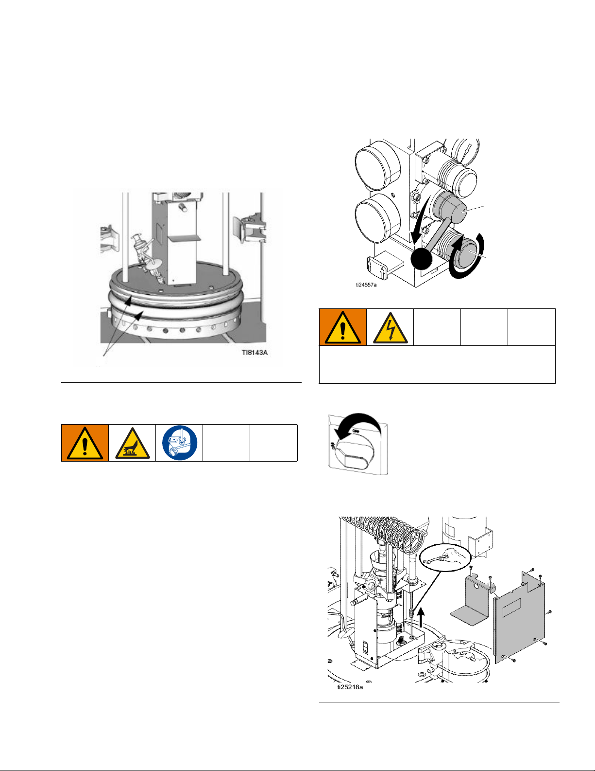
Repair
V
CC
CB
Repair
Replace Wipers
1. To replace a worn or damaged wiper (V) raise the
Ram Plate up out of the drum. Perform steps 1
through 7 of Change Drums, page 38. See wiper kit
manual for instructions about replacing the wipers.
FIG. 25: Replace Wiper
2. Make sure the Ram Plate is down and the Ram
Director Valve is in the OFF position.
To reduce the risk of injury or damage to equipment,
make sure the Main Power Switch is OFF before con-
tinuing with this procedure.
Replace Platen RTD
Reference Electrical Schematics, page 62, for wiring
connections.
1. If the material drum has already been removed from
the supply unit, go to step 2. If you need to remove
the material drum, see Change Drums, page 38.
3. Turn the Main Power Switch OFF.
4. Remove the Pump cover.
FIG. 26: Pump Covers and Platen RTD
334130T 49
Page 50
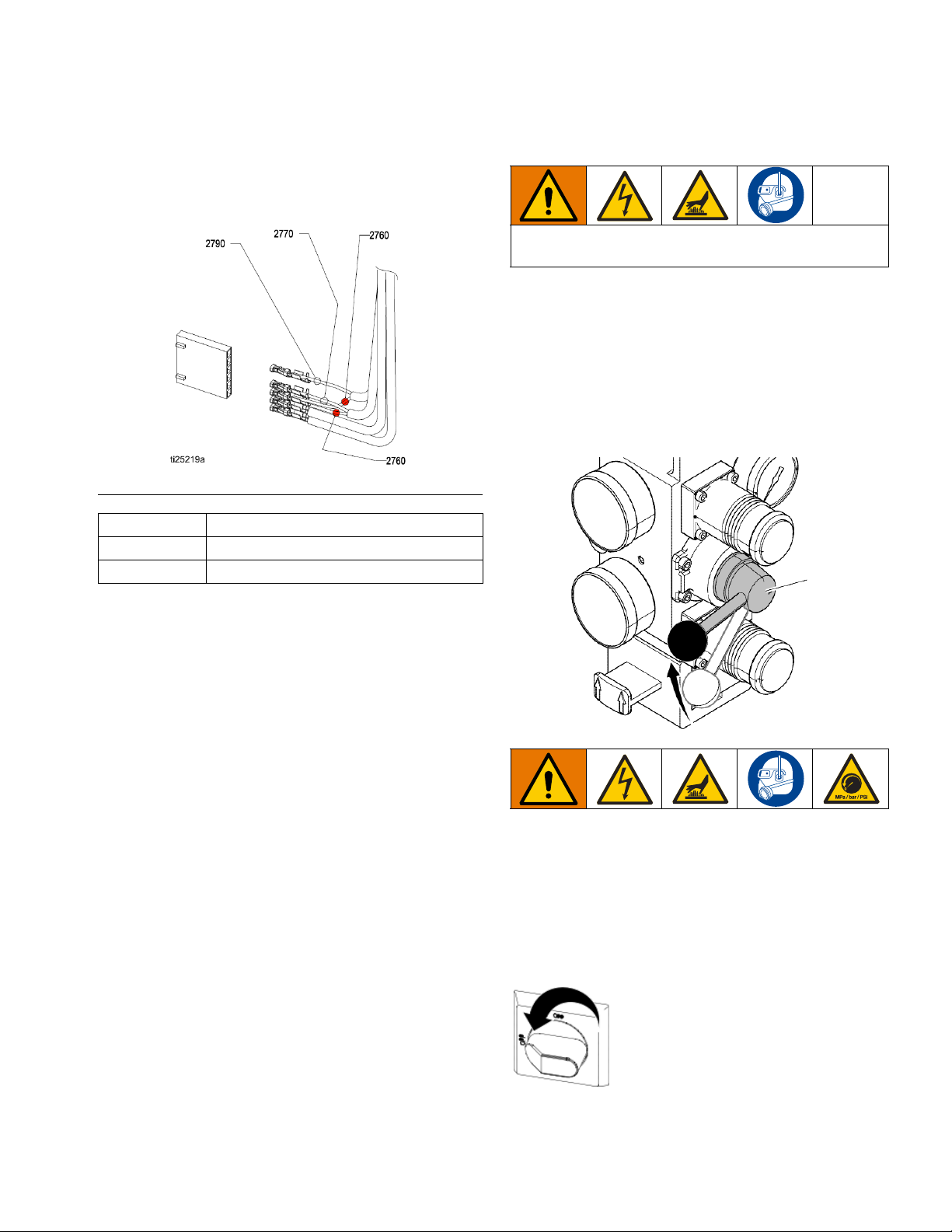
Repair
CC
ti24671a
5. Remove the Platen RTD (605) from the Platen.
6. Disconnect the Platen RTD wires from pin 3 and pin
6 from the J5 connector on MZLP MZTCM-1 or
MZTCM-5.
FIG. 27: RTD Wire Connections
2760 Red
2770 White
2790 White
Separate the Air Motor and Pump
This procedure must be done with the unit still warm.
The material and equipment will be hot!
1. If the material drum has already been removed from
the supply unit, go to step 2. If you need to remove
the material drum, perform steps 1 through 6 of the
Change Drums section, page 38. Pump must be in
the full down position (Air Motor shaft fully
extended).
2. Make sure the Ram Plate is down and the Ram
Director Valve (CC) is in the neutral position.
7. Attach the leads from the new sensor to the leads of
the old sensor and pull the new sensor leads
through the cable pump shield, Cable Track, and
into the Electrical Enclosure.
8. Install the new sensor (605) into the follower/tire
plate after coating with non-silicone heat sink com-
pound. Tighten compression nut. Ensure RTD is
fully inserted.
9. Connect the red and white wires from the new sen-
sor to the J5 connector on MZLP MZTCM-1 or
MZTCM-5.
10. Replace the Pump covers.
3. Follow Pressure Relief Procedure on page 35.
4. Bleed off excess material and pressure in the sys-
tem by opening the dispense gun and catching the
material in a waste container.
5. On the ADM, turn off the system heat (D).
6. Turn the Main Power Switch OFF.
7. Disconnect all material hoses.
50 334130T
Page 51
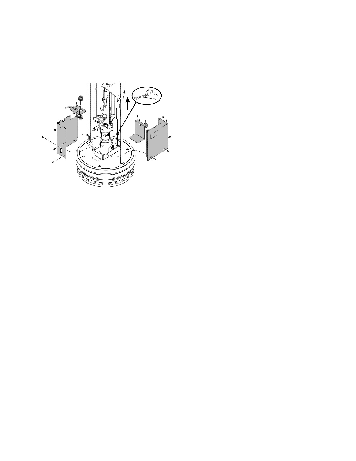
Repair
8. Remove the Pump sheet metal enclosure.
a. Remove the cover screws.
b. Remove the heater bands and disconnect the
ground wire.
9. If vent hood is installed, remove it.
22. Reverse this procedure to reinstall the new or rebuilt
Air Motor.
10. Remove the Air Motor top cover.
11. Disconnect the electrical cable from the Air Motor.
12. Remove air line from Air Motor and air lines to the
follower blow-off valve.
13. Tightly strap the Air Motor to the tie bar with a cable
through the Air Motor lift ring and around the tie bar.
See F
IG
. 29, page 53.
14. Loosen u-bolts (X) from Platen lift rods.
15. Remove nuts (F) from Heated Pump/Air Motor
stand-off rods at the Pump end.
16. Remove nuts (Z) and bolts holding cable tract to Air
Motor support plate.
17. Slide end of Cable Track outboard of the mounting
plate.
18. Remove nuts (N) from follower lift rods.
19. Fully loosen Pump rod coupler to the Air Motor rod
(G).
20. Slowly raise elevator to achieve enough separation
of the Pump (Air Motor) tie rods to remove the
Pump.
21. Remove the Pump.
334130T 51
Page 52
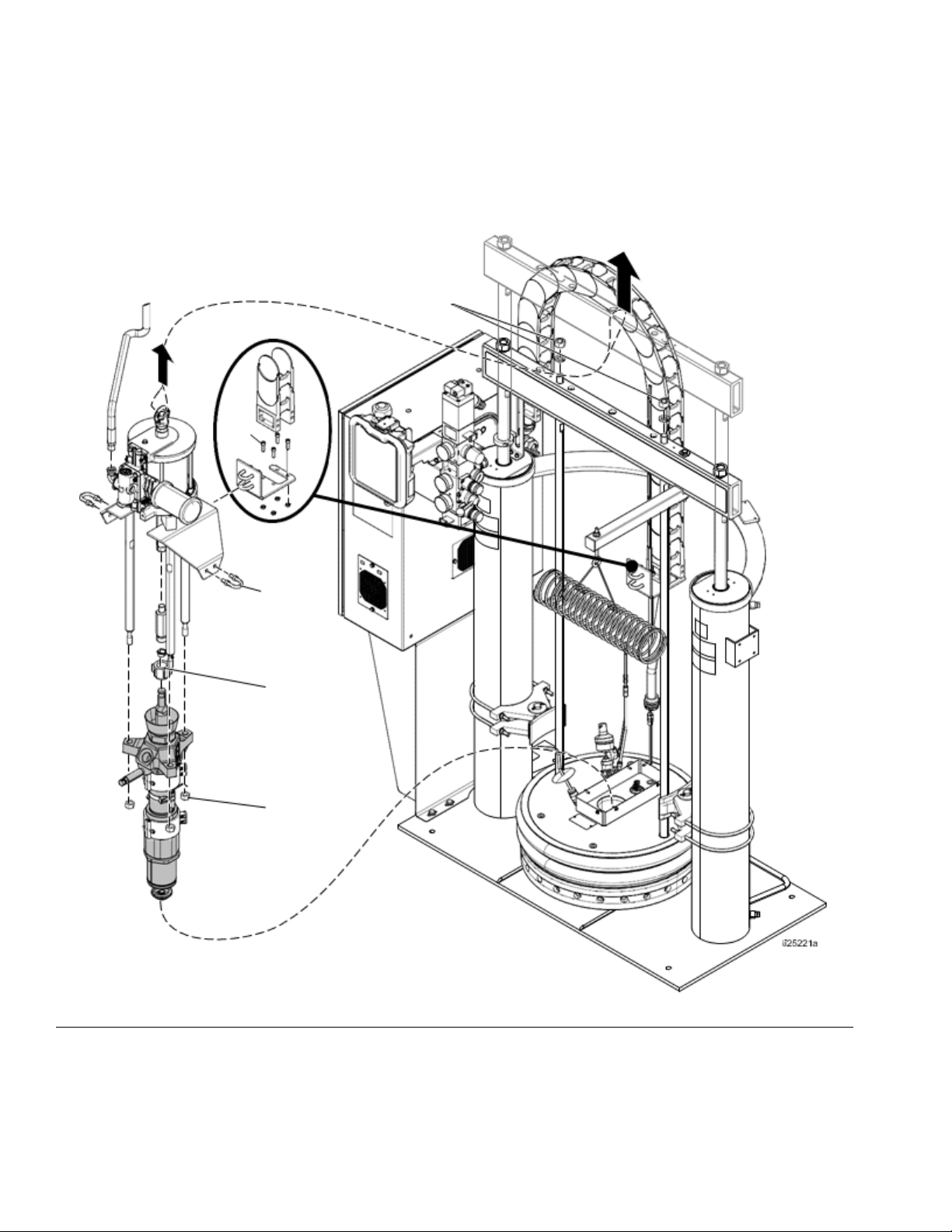
Repair
Z
N
X
G
F
FIG. 28
52 334130T
Page 53
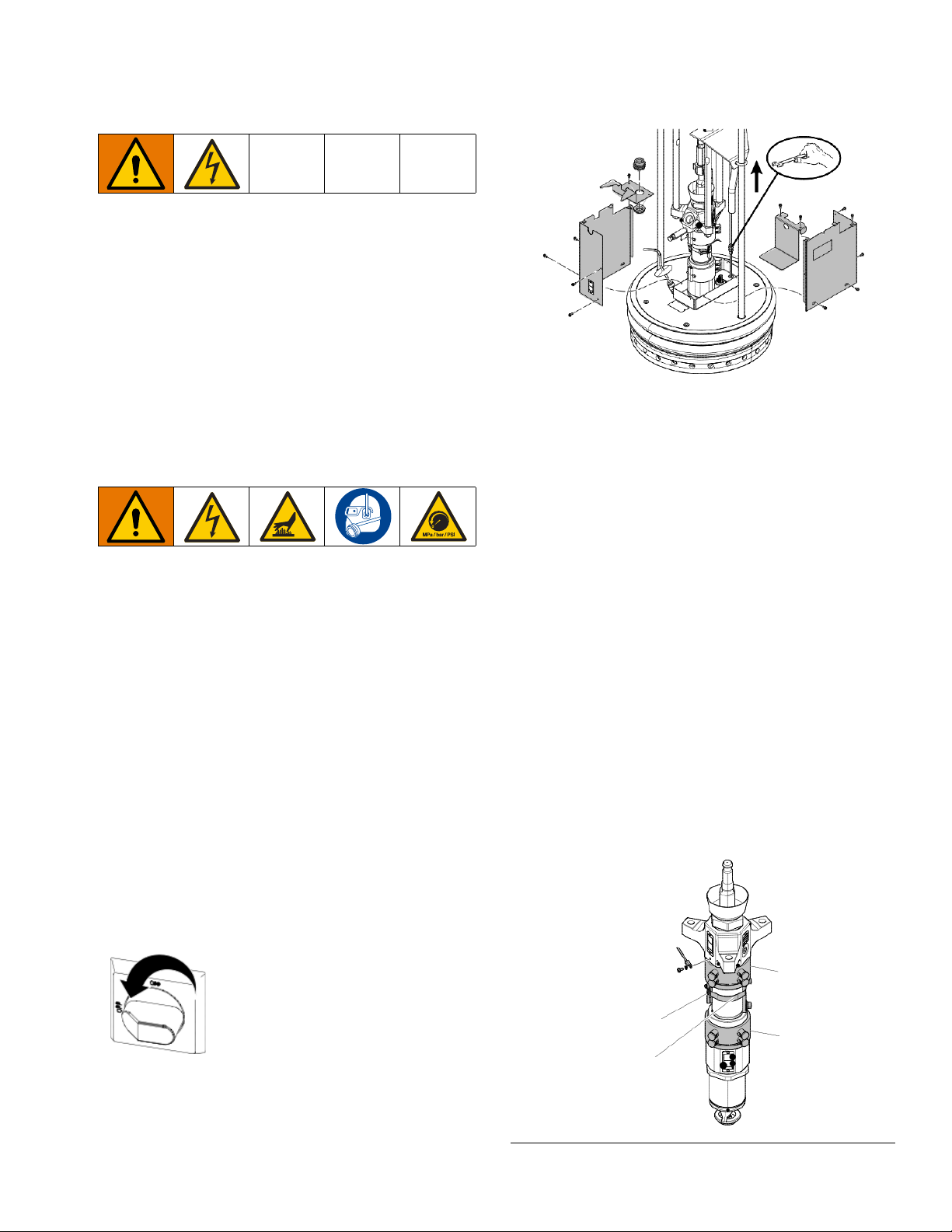
Repair
309a
309b
320
321
ti25222a
Remove Platen
1. Turn the Main Power Switch OFF.
2. Disconnect the Platen power wires and the ground
wire from within the main control panel and pull out
of conduit.
3. Remove the Platen assembly from the Ram.
4. Reverse this procedure to reinstall the new or rebuilt
Platen assembly.
Replace Heater Band and Pump RTD
8. Remove the screws and covers.
9. Remove white ceramic caps and disconnect the
electrical wires from the heater band (309).
10. Remove the screw that holds the heater band in
place.
11. Remove the heater band (309a, 309b) from the
Pump.
Replace Heater Band
1. If the material drum has already been removed from
the supply unit, go to step 2. If you need to remove
the material drum, perform steps 1 through 6 of the
Change Drums, page 38. Pump must be in the full
down position (Air Motor shaft fully extended).
2. Make sure the Ram Plate is down and the Ram
Director Valve is in the neutral position.
3. Follow the Pressure Relief Procedure, page 35.
4. Bleed off excess material and pressure in the sys-
tem by opening the applicator and catching the
material in a waste container.
5. On ADM, turn off the system heat (D).
6. Turn the Main Power Switch OFF.
7.
12. Coat the inside of the heater with non silicone heat
sink compound before mounting. Maximum thick-
ness is 0.005 in. Coat only to within 3/4 in. of vertical
ends.
13. Install a new heater band (309a, 309b) in the same
location as the old heater band:
a. Locate heater terminals so they line up with the
back of the Pump.
b. Tighten the heater band.
c. Re-connect the heater wires and re-attach the
ceramic caps that insulate the terminal.
334130T 53
FIG. 29
Page 54
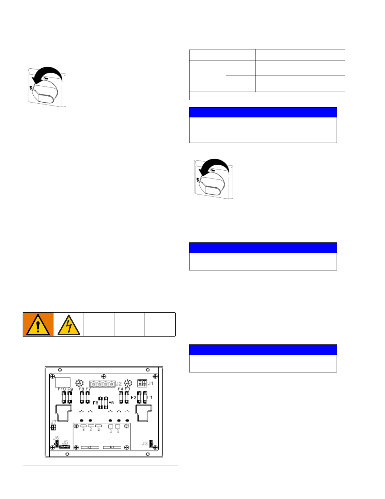
Repair
Replace Pump RTD
1. Turn the Main Power Switch OFF.
Fuse Kit Fuse Part
F1, F2 250VAC, 25A, long, white
24V289
F3-F10 250VAC, 8A, fast acting, clear
Spare fuse kit included with system.
ceramic
glass
2. Remove the screws that hold the front shroud in
place and remove the front shroud.
3. If the sensor wire is connected to the Electrical
Enclosure, disconnect it.
4. Loosen the clamp (321) holding the sensor on the
Pump.
5. Tie the leads of the new sensor (320) to the old sen-
sor and remove the old sensor. The leads of the
new sensor will be easily drawn through the conduit
for reconnecting.
6. Replace the sensor (320) in the clamp (321):
a. Place the sensor approximately 30° counter
clock-wise from the Pump outlet.
b. Tighten the clamp (321).
7. Re-connect the sensor wire to the Electrical Enclo-
sure.
NOTICE
To prevent system damage, always use fast acting
fuses. Fast acting fuses are required for short-cir-
cuit protection.
1. Turn the Main Power Switch OFF.
2. Open Electrical Enclosure door.
3. Use a proper non-conductive fuse puller tool to
remove the blown fuse.
NOTICE
Using an improper tool, such as screw drivers or
pliers, may break the glass on the fuse.
NOTE: F1 and F2 are white ceramic and indicate 25A
on the barrel.
Replace MZLP Fuse
Each MZLP module comes with the following fuses:
FIG. 30: Fuse Locations
54 334130T
NOTE: F3-F10 are clear glass and indicate 8A on the
barrel.
4. Use a proper non-conductive fuse puller tool to
install the new fuse.
NOTICE
Using an improper tool, such as screw drivers or
pliers, may break the glass on the fuse.
5. Close the Electrical Enclosure.
Page 55
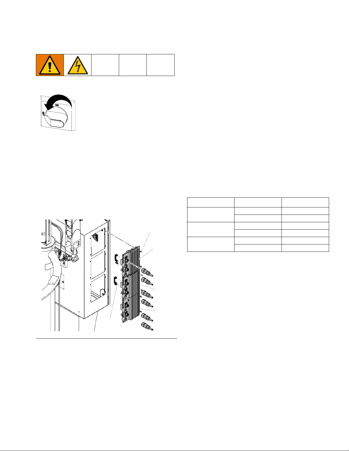
Repair
112
112
J5
ti25223a
115
111
Replace MZLP
1. Turn the Main Power Switch OFF.
2. Disconnect the heated hose electrical connectors
from the MZLP (111 or 112).
3. Note the location of each cable, then unplug all
cables from the MZLP (111 or 112) that will be
replaced.
4. Remove the four screws (115) securing the MZLP
(111 or 112) to the Electrical Enclosure, then carefully remove the MZLP from the Electrical Enclo-
sure.
6. To reassemble the MZLP, set the MZLP rotary
switch based on location. See MZLP Rotary Switch
Table.
7. Use the four screws (115) to install MZLP (111 or
112) to Electrical Enclosure.
8. Reconnect the cables to the MZLP.
NOTE: Do not force the electrical connection. Minimal
force is required to seat the connector. If resistance is
felt, stop and verify the connector orientation.
NOTE: If unable to determine the connector location,
see Electrical Schematics, page 62.
9. Connect the heated hose electrical connectors to
the new MZLP.
NOTE: The MZLP may need updated software. See
Update Software, page 61.
Table 10 MZLP Rotary Switch
MZLP System Rotary Switch
#1 with Daughter
Card
#2 Primary 2
#3 Primary 3
Primary 1
Secondary 5
Secondary 6
Secondary 7
FIG. 31: MZLP Identification
5. Replace MZLP.
a. To replace MZLP #1, remove the daughter card
and standoffs, and re-install them on the new
MZLP #1.
b. To replace MZLP #2 of #3, remove the jumper
(162) from MZLP #2 or #3 J5 connector and
reinstall it on the new MZLP J5 connector.
334130T 55
Page 56
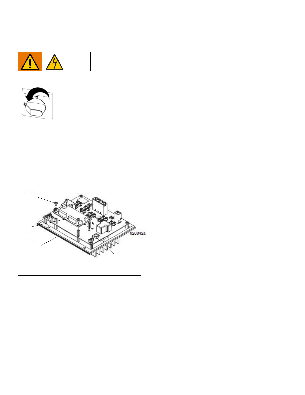
Repair
112b
112a
112
Rotary Switch
Replace MZLP Daughter Card
1. Turn the Main Power Switch OFF.
2. Note the location of each cable, then unplug all
cables from the MZLP daughter card on MZLP #1
(112).
3. Remove the four mounting screws (112b) from the
daughter card (112a) and set aside.
4. Unplug the daughter card (112a) from MZLP #1
(112).
5. Plug the new daughter card (112a) into the MZLP
(112).
6. Use the screws (112b) to secure the daughter card
to the MZLP (112).
7. Connect the cables to the new daughter card
(112a).
NOTE: Do not force the electrical connection. Minimal
force is required to seat the connector. If resistance is
felt, stop and verify the connector orientation.
NOTE: If unable to determine the connector location,
see Electrical Schematics, page 62.
FIG. 32: MZLP Daughter Card
56 334130T
Page 57
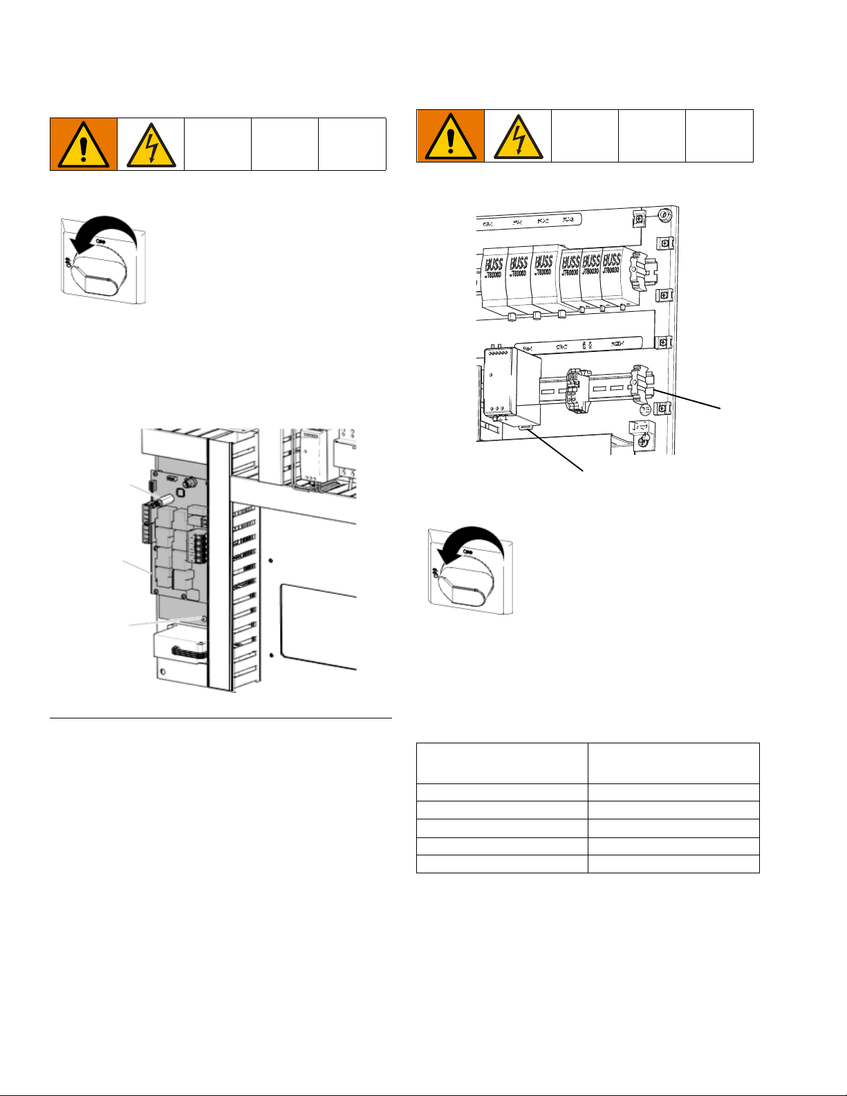
Repair
182
205
223
ti25224a
206
208
Replace AWB
1. Turn the Main Power Switch OFF.
2. Note the location of each cable, then unplug all
cables from the AWB (205).
NOTE: For an AWB on a secondary system, remove the
connector (182) and connect to the new AWB.
Replace Power Supply
FIG. 33: AWB Connections
3. Remove the two screws (223) securing the AWB
(205) to the electrical panel, then carefully remove
the AWB.
4. Install the new AWB (205) and reconnect the
cables.
NOTE: Do not force the electrical connection. Minimal
force is required to set the connector. If resistance is
felt, stop and verify the connector orientation.
NOTE: See Electrical Schematics, page 62, if unable
to determine the connector location.
1. Turn the Main Power Switch OFF.
2. Open the Electrical Enclosure.
3. Remove the power supply (208) from the din rail
(206). Disconnect the screw terminal connections
between the power supply and the power supply
harness.
Power Supply
Connection Harness Label
V+ V+
V- V-
GND GND
LL
NN
4. Connect the power supply harness to the new
power supply.
5. Reattach the power supply to the din rail (206).
6. Torque terminals to 4.53-6.2 in-lbs (0.5-0.7 N•m).
334130T 57
7. Close the Electrical Enclosure door.
Page 58
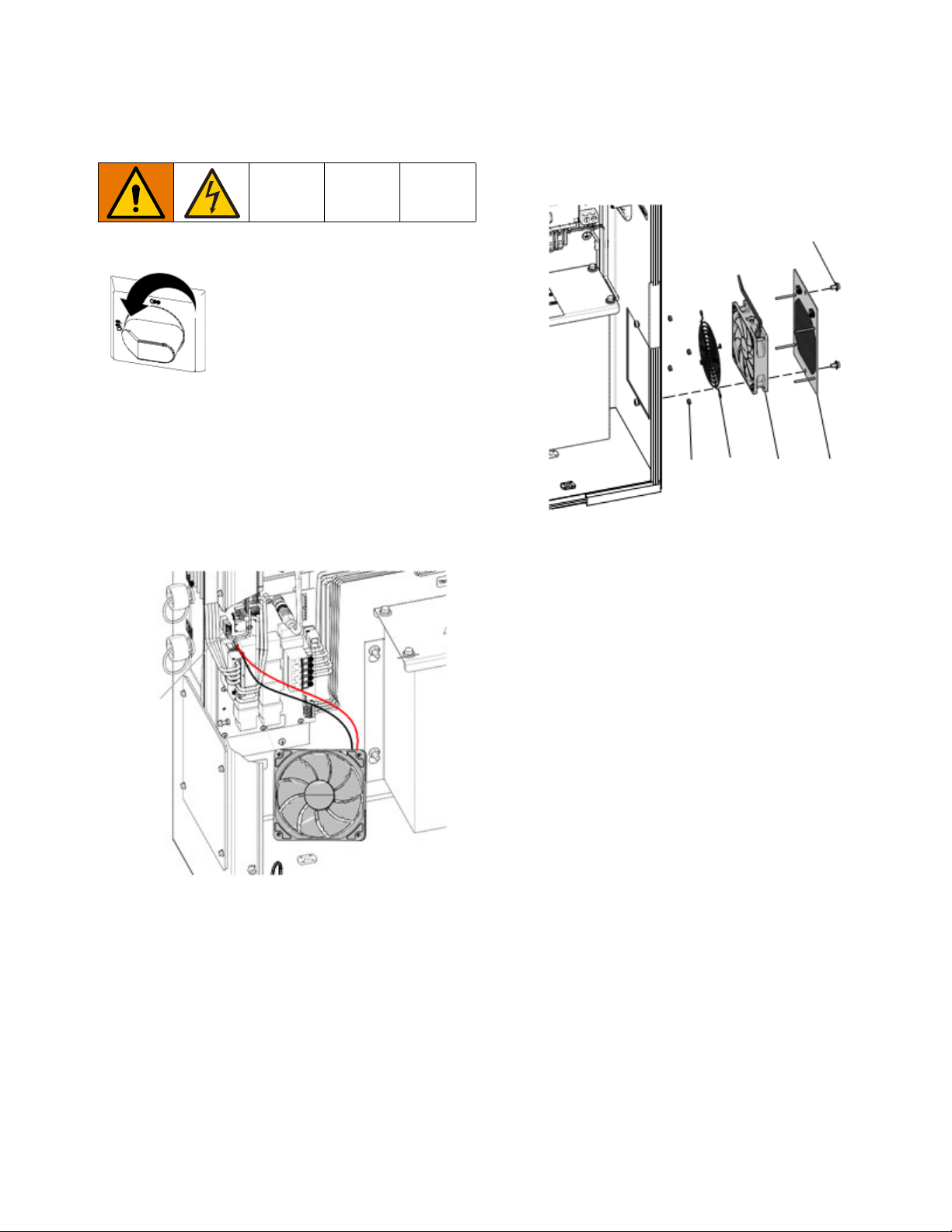
Repair
ti25226a
J7
137
136138
139
141
ti25227a
Replace Fan
1. Turn the Main Power Switch OFF.
2. Disconnect the plug from the power outlet or turn off
the circuit breaker for incoming power.
3. Open the Electrical Enclosure door.
4. Remove the connector from the J7 connector on the
AWB board. Remove the red (+) and black (-) fan
wires from the connector.
6. Remove the screws (141), grill (137), four nuts
(139), rear fan grill (138), and fan (136).
7. Mount the new fan (136), rear fan grill (138), and
nuts (139) on the grill (137) with the arrow pointing
toward the grill (137).
5. Cut any cable ties between the end of the fan wires
to the fan (136).
8. Tie down the fan wires onto the tie down locations
on the grill (137) using cable zip ties.
9. Route the fan wires into the Electrical Enclosure.
Connect the red and black fan wires to the J7 con-
nector. Reconnect the J7 connector to the AWB.
Use cable ties to secure the fan wires to other
cables in the electrical enclosure.
NOTE: To prevent fan errors on the ADM, remove the
excess slack and ensure that the cabling and zip ties do
not contact the fan blades.
10. Reinstall the fan grill (137) and close the Electrical
Enclosure.
58 334130T
Page 59
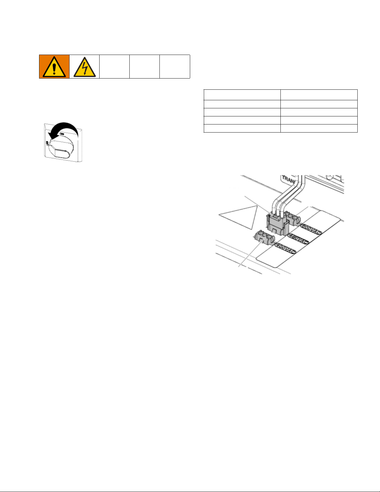
Repair
480VAC
600VAC
400VAC
ti25228a
Replace Transformer
See FIG. 34, page 60.
1. Turn the Main Power Switch OFF.
2. Open the Electrical Enclosure door.
3. Disconnect the incoming power harness (234) from
the top of the transformer (235).
4. Disconnect the transformer (235) output power har-
ness wires (CR2-W1, -W2, -W3, -W4) from CR2.
13. Connect transformer output power harness (234) to
power terminal connections. Torque to 25–27 in-lbs
(2.8–3.1 N•m).
Table 11 Transformer Output Power Harness
Connections
Power Harness Wires CR-2 Connections
CR2-W1 Terminal 1
CR2-W2 Terminal 3
CR2-W3 Terminal 5
CR2-W4 Terminal 13
14. Install the incoming power harness (234) to the top
of the transformer in the voltage port specified on
the machine serial number label.
5. Disconnect the transformer (235) ground wire from
the back panel ground lug.
6. Disconnect the red (+) and black (-) wire of the fan
from pins 4 and 3 of the J7 connector on the AWB
(205). Disconnect the J7 connector from the AWB.
7. Cut the wire zip ties securing the fan wires.
8. Remove the flanged nuts (N) and transformer (235)
from the back panel (201).
9. Install the transformer (235) onto mounting studs on
the back panel (201) and secure with flanged nuts
(N).
10. Insert the thermal sensor connector from the trans-
former (235) onto the J7 connector on the AWB
(205).
11. Reconnect the red (+) wire from the fan into pin 4
and the black (-) wire into pin 3 of the J7 connector.
12. Install the transformer (235) ground wire onto the
ground lug of the back panel (201).
15. Verify all electrical connections, including earth
grounds, are complete and tight. All connections
and plugs must be connected prior to applying
power.
16. Close the Electrical Control Panel door.
17. Apply power to the machine. Turn on the Main
Power Switch.
18. Restart the system.
334130T 59
Page 60

Repair
201
N
235
234
G
Z
J7
205
CR-2
FIG. 34: Inside of Electrical Control Enclosure
60 334130T
Page 61

Repair
T
Update Software
When software is updated on the ADM, the software is
then automatically updated on all connected GCA com-
ponents. A status screen is shown while software is
updating to indicate progress.
1. Turn the system Main Power Switch OFF.
2. Remove the ADM from the bracket.
3. Remove the token access panel.
NOTE: When the Screen turns on, you will see the fol-
lowing screens:
First:
Software is checking which
GCA modules will take the
available updates.
Second:
Status of the update with
approximate time until
completion.
Third:
Updates are complete.
Icon indicates update success/failure. See the fol-
lowing Icon table.
4. Insert and press the software upgrade token (T)
firmly into the slot.
NOTE: There is no preferred orientation of the token.
5. Install the ADM into the bracket.
6. Turn the system Main Power Switch ON.
NOTICE
A status is shown while software is updating to indi-
cate progress. To prevent corrupting the software
load, do not remove the token until the status
screen disappears.
Icon Description
Update successful.
Update unsuccessful.
Update complete, no changes necessary.
Update was successful/complete, but one
or more HCA modules did not have a CAN
boot-loader, so software was not updated
on that module.
7. Remove the token (T).
8. Replace the token access panel.
9. Press to continue to the operation screens.
334130T 61
Page 62
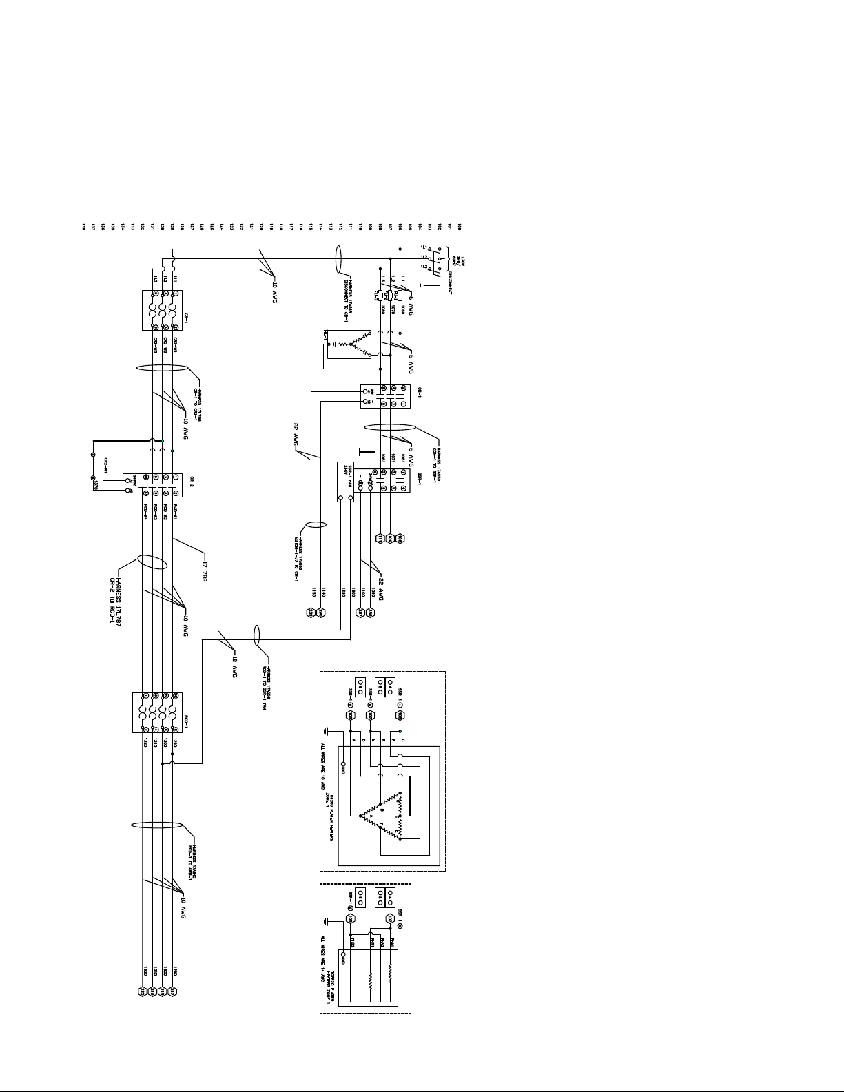
Electrical Schematics
Electrical Schematics
230V, 3 Phase/60Hz
62 334130T
Page 63

400V, 3 Phase/50Hz
Electrical Schematics
334130T 63
Page 64
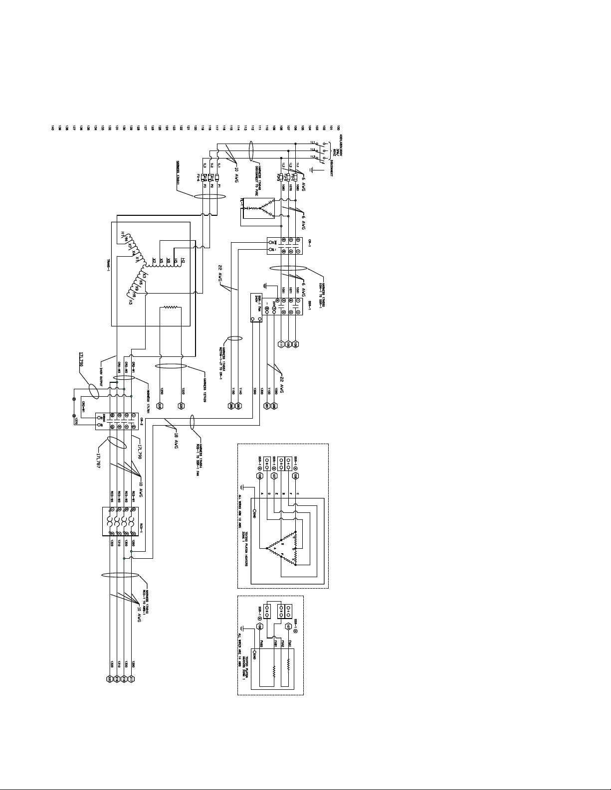
Electrical Schematics
400-600VV, 3 Phase/60Hz
64 334130T
Page 65
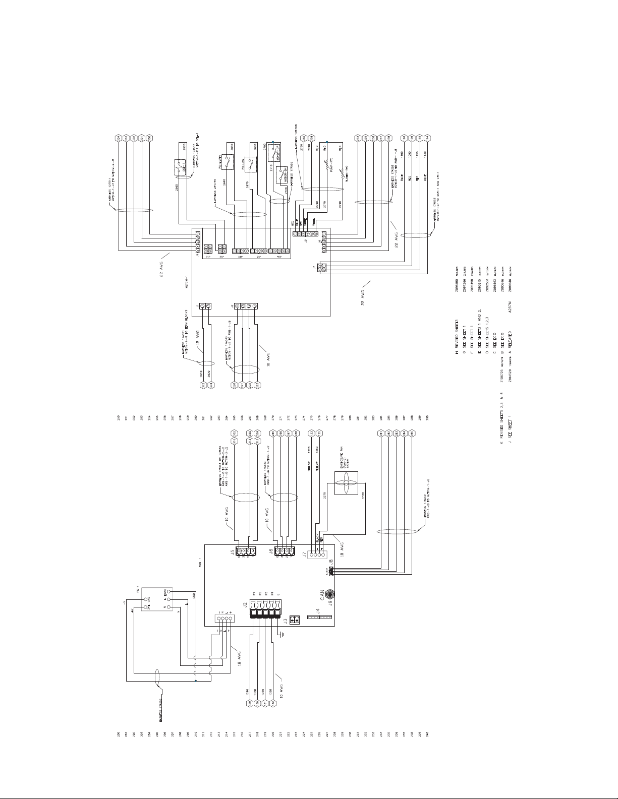
A RELEASED A257M
Z090146
06/24/14
B SEE ECO
Z090616
07/23/14
C SEE ECO
Z091443
08/26/14
D SEE SHEETS 1,2,3
Z092531
10/17/14
E SEE SHEETS 1 AND 2.
Z093615
12/04/14
F SEE SHEET 1
Z095498
23MAR15
G SEE SHEET 1
Z097266
02JUN15
H REVISED SHEET3
Z098180
30JUN15
J SEE SHEET 1
Z104520
17MAR16
K REVISED SHEETS 2,3, & 4
Z106725
06/16/16
J5
J6
J7
J8
J9
J4
J3
J2
CAN
200
201
202
203
204
205
206
207
208
209
210
211
212
213
214
215
216
217
218
219
220
221
222
223
224
225
226
227
228
229
230
231
232
233
234
235
236
237
238
239
240
250
251
252
253
254
255
256
257
258
259
260
261
262
263
264
265
266
267
268
269
270
271
272
273
274
275
276
277
278
279
280
281
282
283
284
285
286
287
288
289
290
J1
AWB-1
24+
GND
N
L
EGND
-
N
L
+
PS-1
129
130
131
265
266
267
268
332
330
329
122
125
ENCLOSURE FAN
(FAN-2)
127421
110
109
115
114
372
374
220
221
222
223
315
313
312
238
237
236
235
234
300
301
302
303
304
281
282
283
284
285
MOTOR-UP
MOTOR-DN
SOL-1
PX-LOW
PX-EMPTY
PUMP-RTD
PLATEN-RTD
54 32 1
G32
1
G32
1
1290
1300
1310
1220
1250
2610
2620
J16 J14J15
J7
J6
J5
J1
J2
MZTCM-1
J13 J12
L1
L3
G
L3L2L1
543214321
4
3
2
1
5 4 3 2 1
5 4 3 2 1
65432
1
4
3
2
1
432
1
4 3
2 1
1140
1150
1090
1100
W1W2W3W4G
2270
2320
2790
RED
2770
2720
2710
2700
2670
2680
2650
2640
2560
2570
-
N
L
+
+V
-V
N
L
GND
132
1320
HARNESS 17A559
AWB-1-J8 TO MZTCM-1-J6
BLACK
YELLOW
YELLOW
RED
-
+
HARNESS 17A543
AWB-1-J6 TO MZTCM-1-J2
HARNESS 17A544 OR 17A545
AWB-1-J5 TO MZTCM-2-J2
AWB-1-J5 TO MZTCM-3-J2
HARNESS 17A543
MZTCM-1-J2 TO AWB-1-J6
HARNESS 17A551
MZTCM-1-J1 TO TERM BLOCKS
HARNESS 17A557
MZTCM-1-J12 TO SOL-1
HARNESS 127511
MZTCM-1-J3 TO MZTCM-2-J6
J3
HARNESS 24V745
HARNESS 17A559
MZTCM-1-J6 TO AWB-1-J8
HARNESS 17A553
MZTCM-1-J7 TO SSR-1 AND CR-1
BLUE
RED
RED
BLUE
HARNESS 17A555
2730
2740
RED
BLUE
RED
WHITE
WHITE
2760
355
358
RED
RED
HARNESS 17B768
HARNESS 17A552
18 AWG
10 AWG
10 AWG
10 AWG
18 AWG
12 AWG
10 AWG
22 AWG
22 AWG
22 AWG
AWB and MZLP#1
Electrical Schematics
334130T 65
Page 66
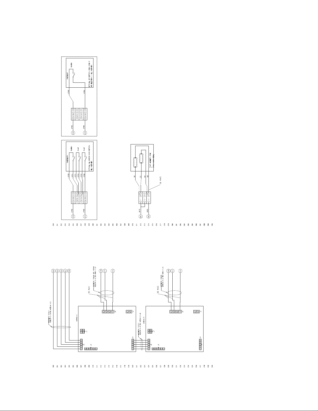
Electrical Schematics
A RELEASED A257M
Z090146
06/24/14
B SEE ECO
Z090616
07/23/14
C SEE ECO
Z091443
08/26/14
D SEE SHEETS 1,2,3
Z092531
10/17/14
E SEE SHEETS 1 AND 2.
Z093615
12/04/14
F SEE SHEET 1
Z095498
23MAR15
G REVISED PUMP WIRING
Z097266
02JUN15
H REVISED SHEET 3
Z098180
30JUN15
J SEE SHEET 1
Z104520
17MAR16
K REVISED SHEETS 2,3, & 4
Z106725
06/16/16
300
301
302
303
304
305
306
307
308
309
310
311
312
313
314
315
316
317
318
319
320
321
322
323
324
325
326
327
328
329
330
331
332
333
334
335
336
337
338
339
340
350
351
352
353
354
355
356
357
358
359
360
361
362
363
364
365
366
367
368
369
370
371
372
373
374
375
376
377
378
379
380
381
382
383
384
385
386
387
388
389
390
B3
T3
262
261
2
240V/1200W TOTAL
2610
2620
215
217
218
254
253
252
251
250
215
217
218
MZTCM-3
MZTCM-2
J7
43
21
J7
J6
J5
J1
J2
L3
L1
G
L3L2L1
54321
54321
65432
1
43
21
J3
HARNESS 127511
MZTCM-2-J3 TO MZTCM-3-J6
J6
J5
54321
65432
1
J1
J2
L3
L1
G
L3L2L1
54321
J3
HARNESS 127511
MZTCM-2-J6 TO MZTCM-1J3
HARNESS 17A544 OR 17A545
MZTCM-2-J2 TO AWB-1-J5
HARNESS 17A545
MZTCM-3-J2 TO AWB-1-J5
B1
T1
321
2740
275
274
2730
2740
2731
2730
2730
2731
2732
2740
2731
2732
2732
PLATEN
PUMP
PUMP
TYPICALL ALL TOF200 AND TOFP20's
OVERTEMPS
ALL VOLTAGES
2740
275
274
2730
2740
2730
2730
2731
2732
2740
PLATEN
TYPICALL OF TOFP20's WITH CODE D
OVERTEMP
AT SELECTION 7. ALL VOLTAGES
10 AWG
10 AWG
16 AWG
MZLP#2, MZLP#3, Overtemp, and Pump Heaters
66 334130T
Page 67
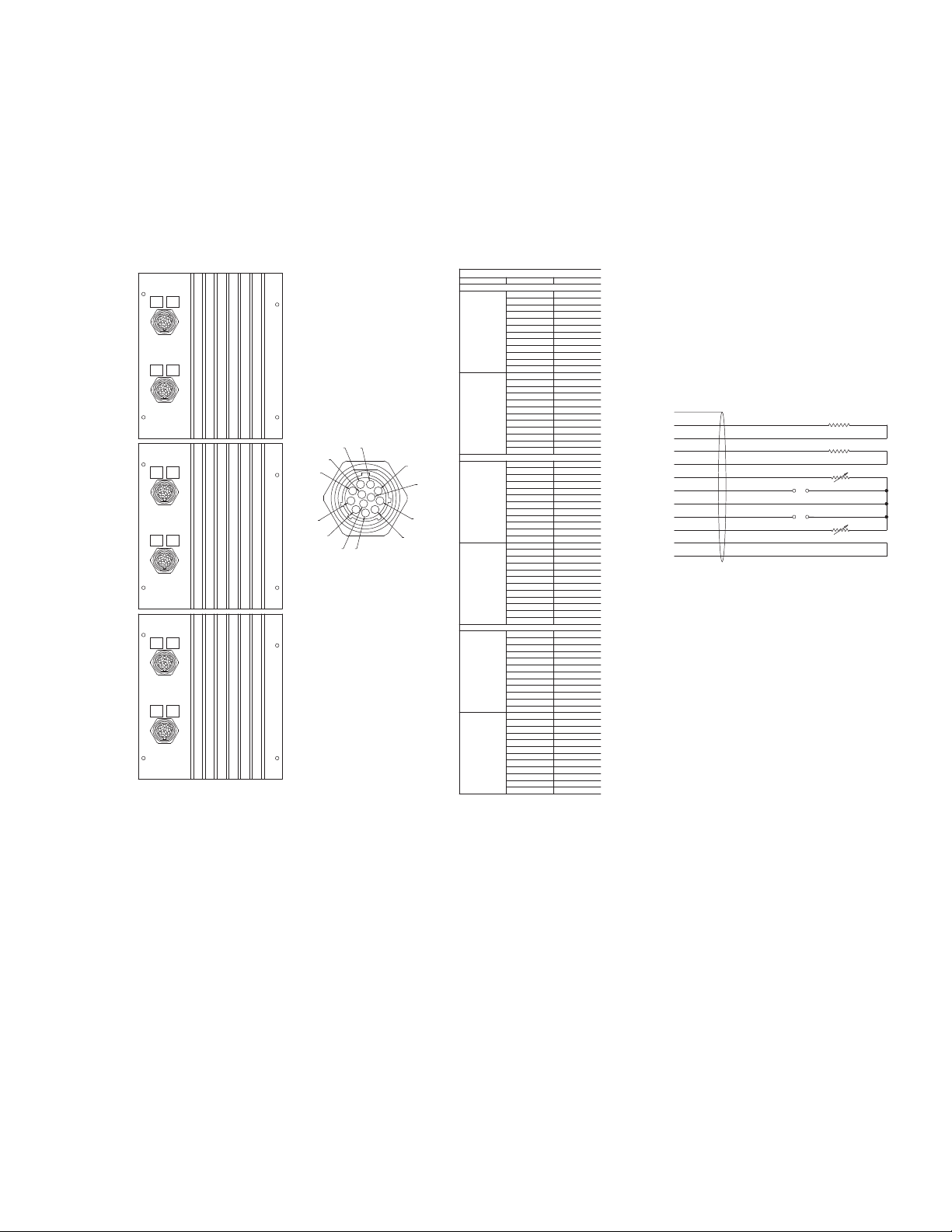
MZLP Zones
A RELEASED A257M
Z090146
06/24/14
B SEE ECO
Z090616
07/23/14
C SEE ECO
Z091443
08/26/14
D SEE SHEETS 1,2,3
Z092531
10/17/14
E SEE SHEETS 1 AND 2.
Z093615 12/04/14
F SEE SHEET 1
Z095498
23MAR15
G SEE SHEET 1
Z097266
02JUN15
H REVISED SHEET 3
Z098180
30JUN15
J SEE SHEET 1
Z104520
17MAR16
K REVISED SHEETS 2,3, & 4
Z106725
06/16/16
400
401
402
403
404
405
406
407
408
409
410
411
412
413
414
415
416
417
418
419
420
421
422
423
424
425
426
427
428
429
430
431
432
433
434
435
436
437
438
439
440
MZTCM-1
J8
J9
C
D
E
F
G
H
J
M
L
K
A
B
TYPICAL ZONE PIN OUT
CONNECTOR PIN # FUNCTION
MZTCM-1
MZTCM-1 J9
A ZONE 1,L2
B SHIELD
C ZONE 2,L1
D ZONE 2,L2
E JUMPER
F ZONE 1,START
G ZONE 1,RTD
H JUMPER
J ZONE 1,L1
K RTD EXCITE
L ZONE 2,START
M ZONE 2,RTD
MZTCM-1 J8
A ZONE 3,L2
B SHIELD
C ZONE 4,L1
D ZONE 4,L2
E JUMPER
F ZONE 3,START
G ZONE 3,RTD
H JUMPER
J ZONE 3,L1
K RTD EXCITE
L ZONE 4,START
M ZONE 4,RTD
MZTCM-2
MZTCM-2 J9
A ZONE 5,L2
B SHIELD
C ZONE 6,L1
D ZONE 6,L2
E JUMPER
F ZONE 5, START
G ZONE 5,RTD
H JUMPER
J ZONE 5,L1
K RTD EXCITE
L ZONE 6,START
M ZONE 6,RTD
MZTCM-2 J8
A ZONE 7,L2
B SHIELD
C ZONE 8,L1
D ZONE 8,L2
E JUMPER
F ZONE 7,START
G ZONE 7,RTD
H JUMPER
J ZONE 7,L1
K RTD EXCITE
L ZONE 8,START
M ZONE 8,RTD
MZTCM-3
MZTCM-3 J9
A ZONE 9,L2
B SHIELD
C ZONE 10,L1
D ZONE 10,L2
E JUMPER
F ZONE 9,START
G ZONE 9,RTD
H JUMPER
J ZONE 9,L1
K RTD EXCITE
L ZONE 10,START
M ZONE 10,RTD
MZTCM-3 J8
A ZONE 11,L2
B SHIELD
C ZONE 12,L1
D ZONE 12,L2
E JUMPER
F ZONE 11,START
G ZONE 11,RTD
H JUMPER
J ZONE 11,L1
K RTD EXCITE
L ZONE 12,START
M ZONE 12,RTD
ZONE-1-RTD
ZONE-2-RTD
ZONE-1-START
ZONE-2-START
ZONE-2-HEAT
ZONE-1-HEAT
A
J
C
D
G
F
K
L
M
E
H
B
TYPICAL ZONE PIN OUT
MZTCM-2
MZTCM-3
J8
J9
J8
J9
21
65
109
43
87
1211
Electrical Schematics
334130T 67
Page 68
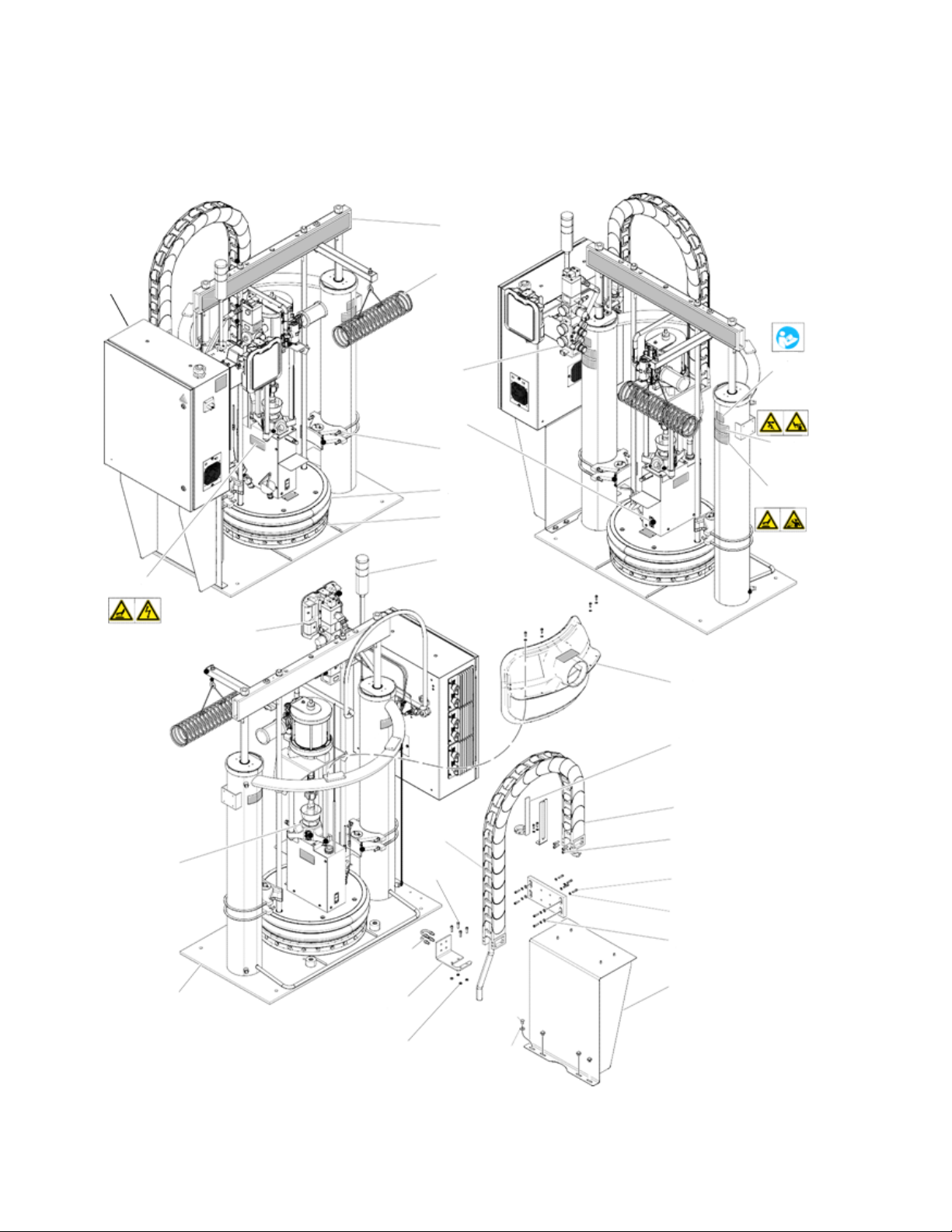
Parts
6
12
3
28
7
8
5
10
9
24
11
16
21
22
23
20
19
18
16
11
15
14
17
1
4
29
2
25
26
27
13
ti25003a
Parts
Therm-O-Flow 200 Supply Unit
68 334130T
Page 69

Therm-O-Flow 200 Supply Unit
Parts
Ref Part Description Qty
1--- Frame 1
2 24W870 KIT, air controls; see Air Control
Assembly, page 70
3 --- CONTROL, electrical 1
4 --- MODULE, pump; see Pump Mod-
ules, page 78
5 --- PLATEN; see Heated Platens,
page 85
6 --- RAM; see ram manual 1
7 --- CLAMP, drum; see Drum Ram
Post Saddle Clamp, page 88
8 --- SEALS, see manual 309196 1
9 24W812 ADM 1
10 24W589 KIT, light tower (optional); see
Accessories and Kits, page 92
11 253288 CABLE, track, IGUS 1
12 234966 KIT, hose hanger 1
13 24V745 SENSOR, level, low/empty 1
14 15H543 BRACKET, mounting 1
▲ Replacement Warning Labels, signs, tabs, and cards
are available at no cost.
1
1
1
1
1
Ref Part Description Qty
15 120186 BOLT, mounting, u-bolt 2
16 101864 SCREW, cap, sch 8
17 111303 NUT, hex 4
18 100575 SCREW, cap, hex hd 4
19 100023 WASHER, flat 4
20 --- BRACKET, mounting, enclosure 1
21 100643 SCREW, cap, sch 4
22 100016 WASHER, lock 4
23 110755 WASHER, plain 4
24 233559 KIT, vent hood (optional); see
Accessories and Kits, page 92.
25▲ 15J076 LABEL, warning, instructions 2
26▲ 15J074 LABEL, warning; moving objects,
pinch
27▲ 15H668 LABEL, warning; hot surface,
splatter
28▲ 15J075 LABEL, warning; hot surface,
shock
29▲ 184090 LABEL, warning 1
1
4
2
2
334130T 69
Page 70
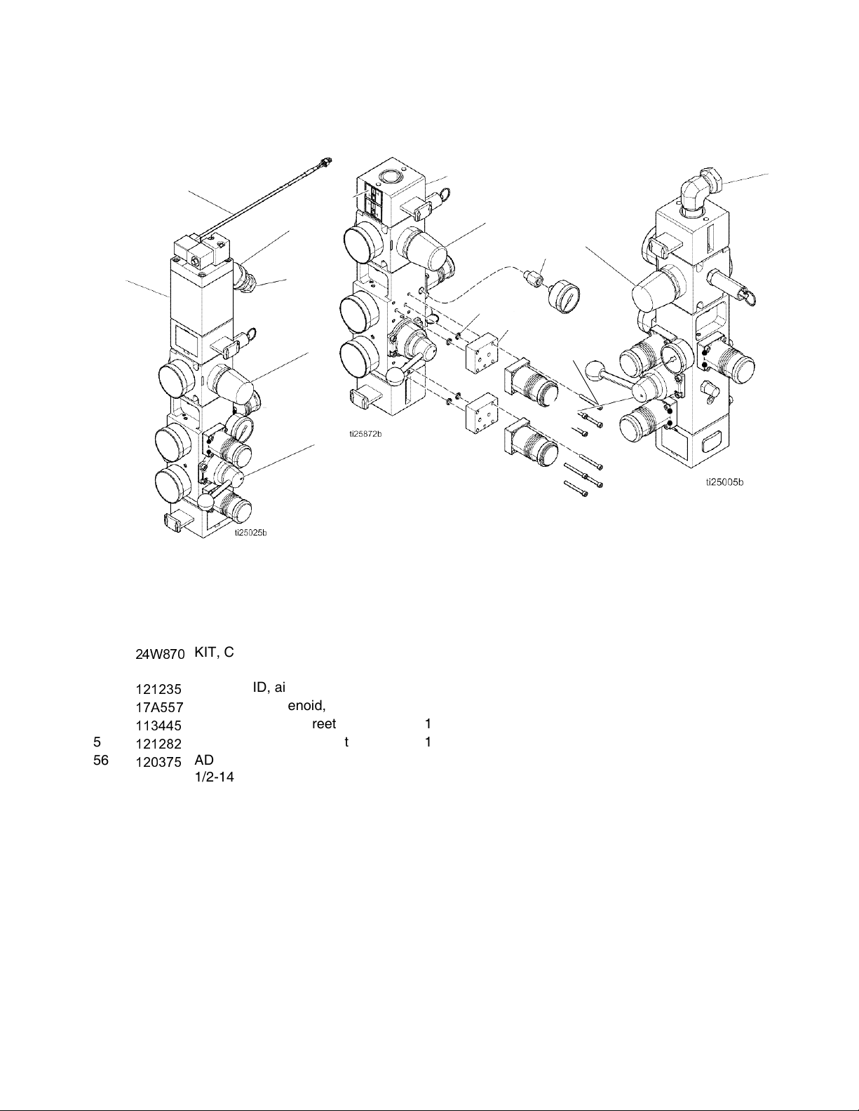
Parts
Integrated Control For
TOF With Electrical Enclosure
24X026, Integrated Control For
Hydraulic TOF With Electrical
Enclosure
Integrated Control For
TOF Without Electrical Enclosure
52
53
54
55
66
51
62
61
66
57
60
59
58
51
66
56
Air Control Assembly
Ref Part Description Qty
51
52
53
54
55
56
57 --- FITTING, adapter, 1/8 x 1/8 NPT(f) 1
58 --- BLOCK, adapter, regulator 2
70 334130T
24W870
121235
17A557
113445
121282
120375
KIT, CONTROL, air, 3 regulator;
see manual 334201
SOLENOID, air motor, ram 1
HARNESS, solenoid, MZLP 1
FITTING, elbow, street 1
FITTING, swivel, straight 1
ADAPTER, elbow, 3/4-14 nptf x
1/2-14 npsm
Ref Part Description Qty
59 --- O-RING 4
1
60 --- SCREW, cap, socket hd; 1.5 in,
#8-32
61 --- CONTROL, air, 3 regulator,
62 --- LABEL, valve, shutoff, air control 1
66 255651 KIT, reg, air motor, ram 1
1
Parts only used with 24X026 on TOF 200 Hydraulic Sys-
tems.
hydraulic
8
1
Page 71
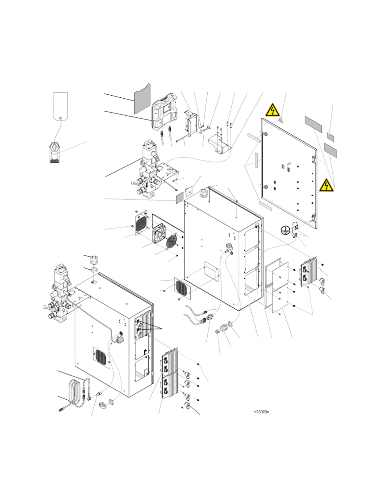
Electrical Module
184
143
144
148 150 152 153
142
106
152
153
105
145
147
149
120
174
222
141
137
136
138
139
140
141
222
160
159
157
158 101
104
103
172
170153146 151
177, 119
222
118
111
116
115
114
113
183
161
131
112
112
116
115
Parts
334130T 71
Page 72
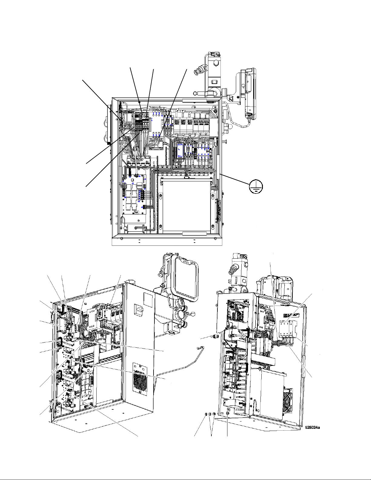
Parts
110
165
167
169
125
126
181
222
128
127 122
168
125
131
165
111
129
130
156
162
124
123
108
109
135
133
132
134
72 334130T
Page 73

Electrical Control Module Parts
Parts
Ref Part Description Qty
101 --- ENCLOSURE, electrical 1
103 --- BUSHING, strain relief, m40
thread
104 --- NUT, strain relief, m40 thread 1
105 125946 PLUG, hole, 1/2 in 2
106 123967 KNOB, operator disconnect 1
107 --- PANEL, elec, transformer
(transformer assemblies only)
--- PANEL, elec, 400v/n
(400V modules only)
--- PANEL, elec, 230v/n
(230V modules only)
108 100133 WASHER, lock, 3/8 4
109 100307 NUT, hex 8
110 123396 NUT, flange, serrated, 3/8-16 4
111 --- MODULE, gca, mzlp w/ daughter
board
112 24V510 MODULE, gca, mzlp
(8 zone assemblies only; Qty 1)
(12 zone assemblies only; Qty 2)
112a 24R042 KIT, daughter, board 1
113 --- GASKET, foam
(8 zone assemblies only; Qty 1)
(12 zone assemblies only; Qty 2)
114 24P175 PLATE, blank
(4 zone assemblies only; Qty 2)
(8 zone assemblies only; Qty 1)
115 125856 SCREW, 8-32, serrated flange 12
116 16T440 CAP, souriau, uts 14
(4 zone assemblies only; Qty 2)
(8 zone assemblies only; Qty 4)
(12 zone assemblies only; Qty 6)
118 --- WIRE, grounding, door 1
119 100166 NUT, full hex 2
120 --- GASKET, hphm 1
122 17A543 HARNESS, power, mzlp1, awb 1
123 17A544 HARNESS, power, mzlp2, awb
(8 zone assemblies only)
17A545 HARNESS, power, mzlp2/3, awb
(12 zone assemblies only)
1
1
1
1
1
1
1
Ref Part Description Qty
125 --- HARNESS, pump, mzlp1, tb, tof 1
126 --- HARNESS, output, mzlp1, ssr,
contact
127 17A555 HARNESS, pump, reed switch, tof 1
128 17A559 HARNESS, board, mxm, comm 1
129 127511 CABLE, board, samtec
(8 zone assemblies only; Qty 1)
(12 zone assemblies only; Qty 2)
130 121226 CABLE, can, male / female, 0.4m 1
131 121612 CONNECTOR, thru, m12, mxf 1
132 123969 SWITCH, disconnect, 100a 1
123968 SWITCH, disconnect, ph exp 100
A (400V only)
134 --- HARNESS, disc, fuse, 230-600v 1
17A547 HARNESS, disc, cb, 400v/n, tof 1
136 24V911 FAN, 24v dc, 120m x 120m
(400V only)
137 16X884 GRILL, fan (400V only) 1
138 115836 GUARD, finger (400V only) 1
139 127278 NUT, keps, hex (400V only) 4
140 24V746 GRILL, vent
(230V and 400V assemblies only;
Qty 2) (Transformer assemblies
only; Qty1)
141 119865 SCREW, mach, hex serrated 4
142 --- CONTROL, air, assy; with sole-
noid
143 24W812 ADM (Primary assemblies only) 1
144 15V551 SHIELD, membrane, ADM
(Primary assemblies only)
145 121001 CABLE, can, female / female 1.0m
(Primary assemblies only)
146 --- BRACKET, mounting, assembly
(Primary assemblies only)
147 121250 SCREW, shcs, 1/4uncx4.25 (Pri-
mary assemblies only)
148 102040
149 110755 WASHER, plain (Primary assem-
150 121253
151 ---
152 101550
NUT, lock, hex
(Primary assemblies only)
blies only)
KNOB, display adj., ram pkgs
(Primary assemblies only)
BRACKET, pendant pivot,
(Primary assemblies only)
SCREW, cap, sch
(Primary assemblies only)
1
1
1
1
0.1
1
1
1
1
1
1
1
4
334130T 73
Page 74

Parts
Ref Part Description Qty
153 100016
WASHER, lock
(Primary assemblies only)
156 24V745 SENSOR, level, low/empty 1
157 --- BUSHING, strain relief 1
158 --- NUT, bushing 1
159 --- GROMMET, wire 1
160 124654
CONNECTOR, splitter, 12(m) x
m12(f)
(Secondary modules only)
161 121228
CABLE, can, female/female,
15.0 m
(Secondary modules only)
162 16W035
CONNECTOR, jumper
(8 zone assemblies only;
Qty 1) (12 zone assemblies only;
Qty 2)
163 ---
CONTACT, socket, 20-24 awg,
crimp, tin
164 --- TUBE, 1/16 shrink tube 0.13
165 ---
166 127771
HARNESS, input, mzlp1, RTD
BRIDGE, plug-in, 2pos, ut16
(400V and Transformer modules
only)
167 ---
FERRULE, wire, 10awg
(230V modules only; Qty 2) (400V
and transformer modules only; Qty
8)
168 --- FERRULE, wire, 16awg 6
169 ---
FERRULE, wire, 18 awg, long
170▲ 196548 LABEL, warning, shock 1
172 --181 ---
ARTWORK, instructions, wiring, ul
FERRULE, wire, 10awg, twin
(Secondary assemblies only)
182 17C669
CONNECTOR, jumper, male
(Secondary assemblies only)
183 123856
HARNESS, CAN, cable
(Secondary assemblies only)
184 17C712
TOKEN
(Secondary assemblies only)
5
1
1
3
1
1
6
1
3
1
1
1
▲ Replacement Warning labels, signs, tags, and cards
are available at no cost.
74 334130T
Page 75
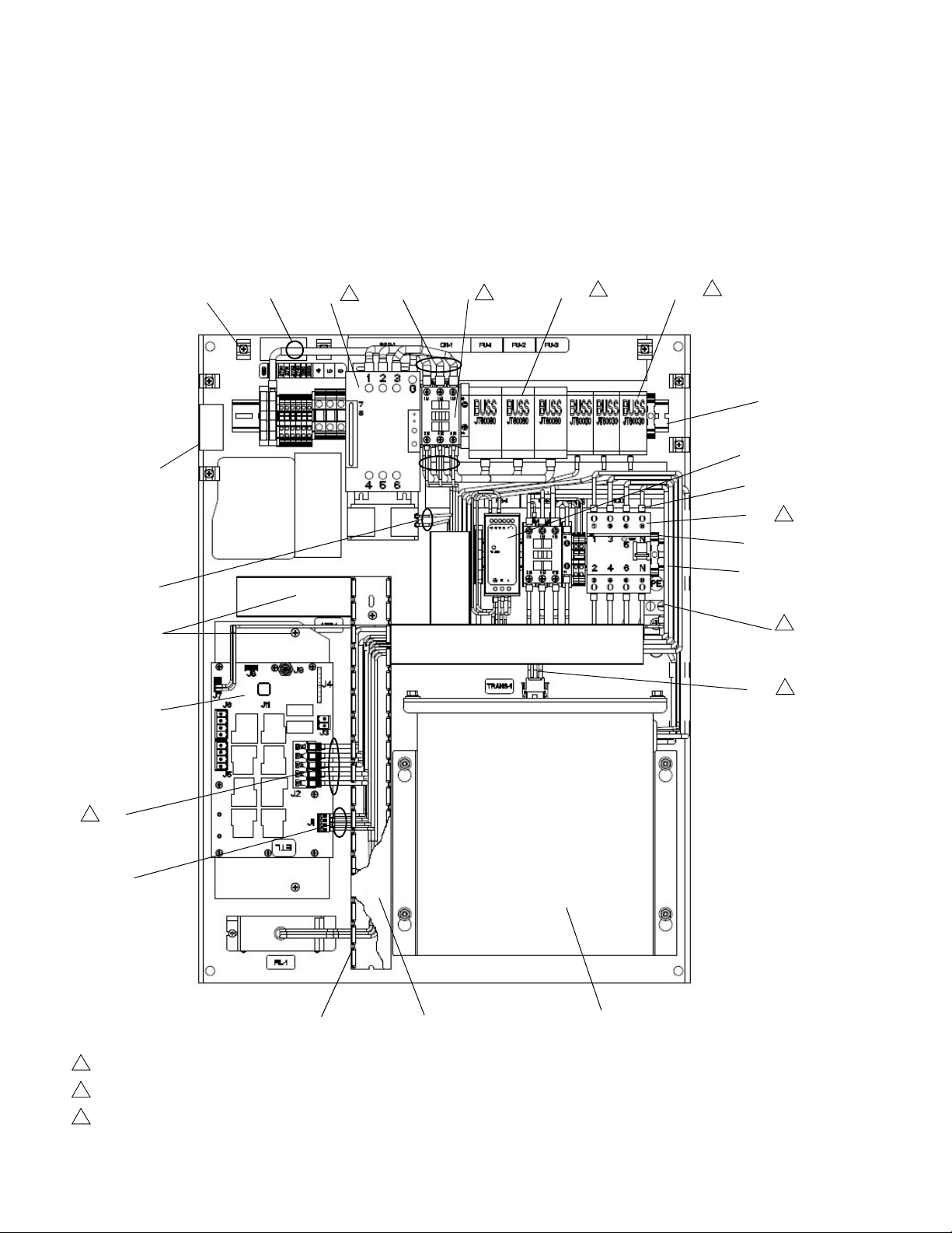
Electrical Panel
Torque terminals to 25-27 in-lbs (2.8-3.1 N•m).
Torque terminals to 13.3-16 in-lbs (1.5-1.8 N•m)
Torque terminals to 4.53-6.2 in-lbs (0.5-0.7 N•m)
123
Transformer Panel Shown
4
239
240
235
211
205
223
228
226
201
223, 224
225
214
1
227
215
1
216, 229
1
230, 231
1
213
208
210
1
212
206
202, 203, 204, 236
7
234
6
241
242
230V
400V
Transformer
Parts
334130T 75
Page 76

Parts
Torque terminals to 25-27 in-lbs (2.8-3.1 N•m).
Torque terminals to 13.3-16 in-lbs (1.5-1.8 N•m)
Torque terminals to 4.53-6.2 in-lbs (0.5-0.7 N•m)
123
230V Panel
400V Panel
230
232
230
233
211
219
243
220
221
207
218
217
1
2
2
3
76 334130T
Page 77

Electrical Panel Parts
Parts
Ref Part Description Qty
201 --202 117666 TERMINAL, ground 1
203 113783 SCREW, machine, pn hd 1
204 100985 WASHER, lock ext 1
205 24V816 MODULE, gca, awb 1
206 --- RAIL, din, 6.5in 1
207 123363
208 126453 POWER SUPPLY, 24v 1
209 ---
210 128097
211 --- HARNESS, rcd, awb 1
212 126811 BLOCK, clamp end 2
213 --- RAIL, din, 19in 1
214 120399
215 123359
216 6690-24
-165
217 128314 BLOCK, terminal 3-wire 8
218 128321 COVER, end 2
219 126819
220 127717
221 127718 COVER, end, ut16 1
222▲ 17C137 LABEL, multi safety 1
223 103833 SCREW, mach, crbh 33
224 123452
225 --226 --- HARNESS, fuse, contactor 1
227 --- HARNESS, contactor, ssr 1
PANEL, elec, tof, 11ga, zinc
BLOCK, terminal, ground, 10mm
HARNESS, power supply, awb
CIRCUIT, breaker, 63a, 4p, rcd
CONTROL, 65 amp, 120-600v
RELAY, contactor, 30a, 3p, 24vdc
co
FUSE, fuse block buss jt60060
BRIDGE, plug-in, 2-position
BLOCK, terminal, 2pos, ut16
HOLDER, anchor, wire tie, nylon
HARNESS, wire, ground, 8awg
1
3
1
1
1
1
3
1
3
12
1
Ref Part Description Qty
228 --- HARNESS, rcd, ssr fan 1
229 --- See Code C Table 3
230 6690-24
-164
127744
127745
231 --- See Code C Table 3
232 17L788
233 17L789
234 17A541
235 24V718
237 128014
238 112380 SCREW, mach, pn hd 2
239 81/0163
-B/11
240 81/0164
-B/11
241 17L790 HARNESS 1
242 129120 CONTACTOR 240V 1
243 17L787 HARNESS 1
▲ Replacement Warning labels, signs, tags, and cards
are available at no cost.
FUSE, fuse block buss jt60030
CIRCUIT, breaker, 3p, 32a, ul489;
230V Panel only
CIRCUIT, breaker, 20a,
4p, ul489; 400V Panel only
HARNESS, cb, rcd, 230-400V;
230V and 400V Panel only
HARNESS, cb, rcd, 400v/n; 400V
Panel only
HARNESS, fuses, transformer;
Transformer panel only
TRANSFORMER, multi-tap/230v,
6kva; Transformer panel only
FILTER, voltage, transient, 600V,
3P
WIREWAY, panduit 4
COVER, panduit 4
3
1
1
1
1
1
1
If Code A is 200 and Code E is M and Code C is If Code A is 200 and Code E is F/S and Code C is
Code C (229) (231) Code C (229) (231)
X1X 24X885 NA X1X 24X885 NA
X2X 24X881 NA X2X 24X880 NA
X3X 24X881 24X878 X3X 24X880 24X878
X4X 24X882 24X877 X4X 24X881 24X877
X5X 24X884 24X874 X5X 24X883 24X874
334130T 77
Page 78

Parts
Torque to 50-60 ft-lbs (68-81 N•m).
Torque to 145-155 ft-lbs (196-210 N•m).
Coat mounting surface of sensor mounting block (322) with
non-silicone heat sink compound. Do not coat sensor.
Prior to tightening band clamp (321), RTD sensor (320)
must be fully contained within the sensor mount (322).
After fastening band clamp (321), secure excess with
fiberglass tape.
12345
Coat inside of heater (309a, 309b) only to within 0.75 in. (19
mm) of vertical ends with non-silicone heat sink compound
before mounting.
Cap screws (311) must be loose while tie rods (307) are
being torqued.
Torque to 150 ft-lb (203 N•m).
Install swivel fitting (302) prior to screw (303) and reed switch
assembly (304).
Apply anaerobic sealant to threads.
678
9
10
ti25145a
333
326
309b
321
322
325
324
323
309a
310
308
329
315
338
301
327
337
302
304
312
318
311
317
316
307
306
318
305
335b
336
335a
334
320
9
8
1
7
10
4
2
6
5
3
6
1
Merkur 2200, 23:1 Pump Modules
78 334130T
Page 79

Merkur 2200, 23:1 Pump Modules
Parts
Ref Part Description Qty
301 24W754
302 155470
304 24R885 SWITCH, reed assy 1
305 --- BRACKET, motor mount 1
306 15H397 ADAPTER, rod, pump 1
307 16A223
308 106166 NUT, mach ,hex 3
309 128322
310 24W150
24W151
311 109211 SCREW, cap, sch 3
312 17A637 BLOCK, standoff, mounting 3
315 102656
316 186925
317 184129
318 120186 BOLT, mounting, u-bolt 2
320 24Z093 SENSOR, RTD 1
MOTOR, air, 6 in, 4.75 stroke, blue
FITTING, swivel, union, 90°
ROD, tie, vert driver
HEATER, pump, 600 watt
PUMP, long shaft, cf; 24V003 only
PUMP, long shaft, gf; 24V006 only
MUFFLER
NUT, coupling
COLLAR, coupling
1
1
3
2
1
1
1
2
Ref Part Description Qty
321 C31012
322 C03507
323 C38162 SCREW, machine 1
324 C38163 WASHER, lock, ext. tooth 1
325 --- CONDUCTOR, ground 1
326 ---
329 103347
330 C33049 TAPE, adhesive, fiberglass 1.5
331 --333 206994 FLUID, tsl 8 oz bottle 1
334 17B715
335 127671
336 122338
337 214656 HOSE, coupled, 10 ft (3 m) 1
338 16C009 HOOK 1
CLAMP
SUPPORT, sensor
SHIELD, pump, tof200; see
24V619, Pump Shield, page 84
VALVE, safety, 100 psi
LUBRICANT, high temp, thermal
SUPPORT, block, overtemp
SWITCH, over temp, fixed, 450°F
(232°C)
SCREW, cap, socket bh
1
1
1
1
1
1
2
4
334130T 79
Page 80
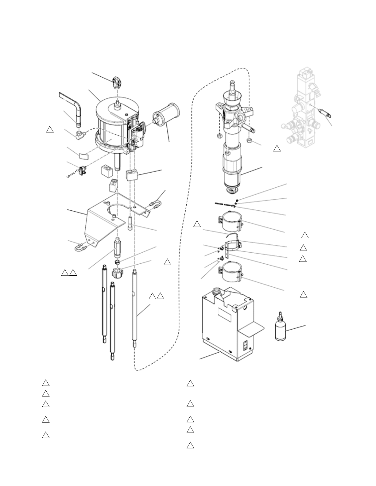
Parts
Torque to 50-60 ft-lbs (68-81 N•m).
Torque to 145-155 ft-lbs (196-210 N•m).
Coat mounting surface of sensor mounting block (322) with
non-silicone heat sink compound. Do not coat sensor.
Prior to tightening band clamp (321), RTD sensor (320)
must be fully contained within the sensor mount (322).
After fastening band clamp (321), secure excess with
fiberglass tape.
12345
Coat inside of heater (309) only to within 0.75 in. (19 mm)
of vertical ends with non-silicone heat sink compound
before mounting.
Cap screws (311) must be loose while tie rods (307) are
being torqued.
Torque to 150 ft-lbs (203 N•m).
Install swivel fitting (302) prior to screw (303) and reed
switch assembly (304).
Apply anaerobic sealant to threads.
6
789
10
338
301
337
327
304
305
318
306
307
316
317
311
318
312
315
326
333
336
335b
335a
336
320
308
310
329
323
324
325
309a
322
321
334
309b
302
8
7
1
2
9
10
1
6
3
5
6
4
Merkur 3400, 36:1 Pump Modules
80 334130T
Page 81

Merkur 3400, 36:1 Pump Modules
Ref Part Description Qty
301 24R015
302 155470
304 24R885 SWITCH, reed assy 1
305 15H173
306 15H397 ADAPTER, rod, pump 1
307 16A223
308 106166 NUT, mach, hex 3
309 128322
310 24W150
24W151
311 109211 SCREW, cap, sch 3
312 17A637 BLOCK, standoff, mounting 3
315 102656
316 186925
317 184129
318 120186 BOLT, mounting, u-bolt 2
320 24Z093 SENSOR, RTD 1
321 C31012
322 C03507
323 C38162 SCREW, machine 1
324 C38163 WASHER, lock, ext. tooth 1
325 --- CONDUCTOR, ground 1
326 ---
329 103347
330 C33049 TAPE, adhesive, fiberglass 1.5
331 --333 206994 FLUID, tsl 8 oz bottle 1
334 17B715
335 127671
336 122338
337 214656 HOSE, coupled, 10 ft (3 m) 1
338 16C009 HOOK 1
MOTOR, assy, air, 7.5 in, blue
FITTING, swivel, union, 90°
BRACKET, motor mount, tof 200
ROD, tie, vert driver
HEATER, pump, 600 watt
PUMP, long shaft, cf; 24V004 only
PUMP, long shaft, gf; 24V007 only
MUFFLER
NUT, coupling
COLLAR, coupling
CLAMP
SUPPORT, sensor
SHIELD, pump, tof200; see
24V619, Pump Shield, page 84
VALVE, safety, 100 psi
LUBRICANT, high temp, thermal
SUPPORT, block, overtemp
SWITCH, over temp, fixed, 450°F
(232°C)
SCREW, cap, socket bh
1
1
1
3
2
1
1
1
1
2
1
1
1
1
1
1
2
4
Parts
334130T 81
Page 82
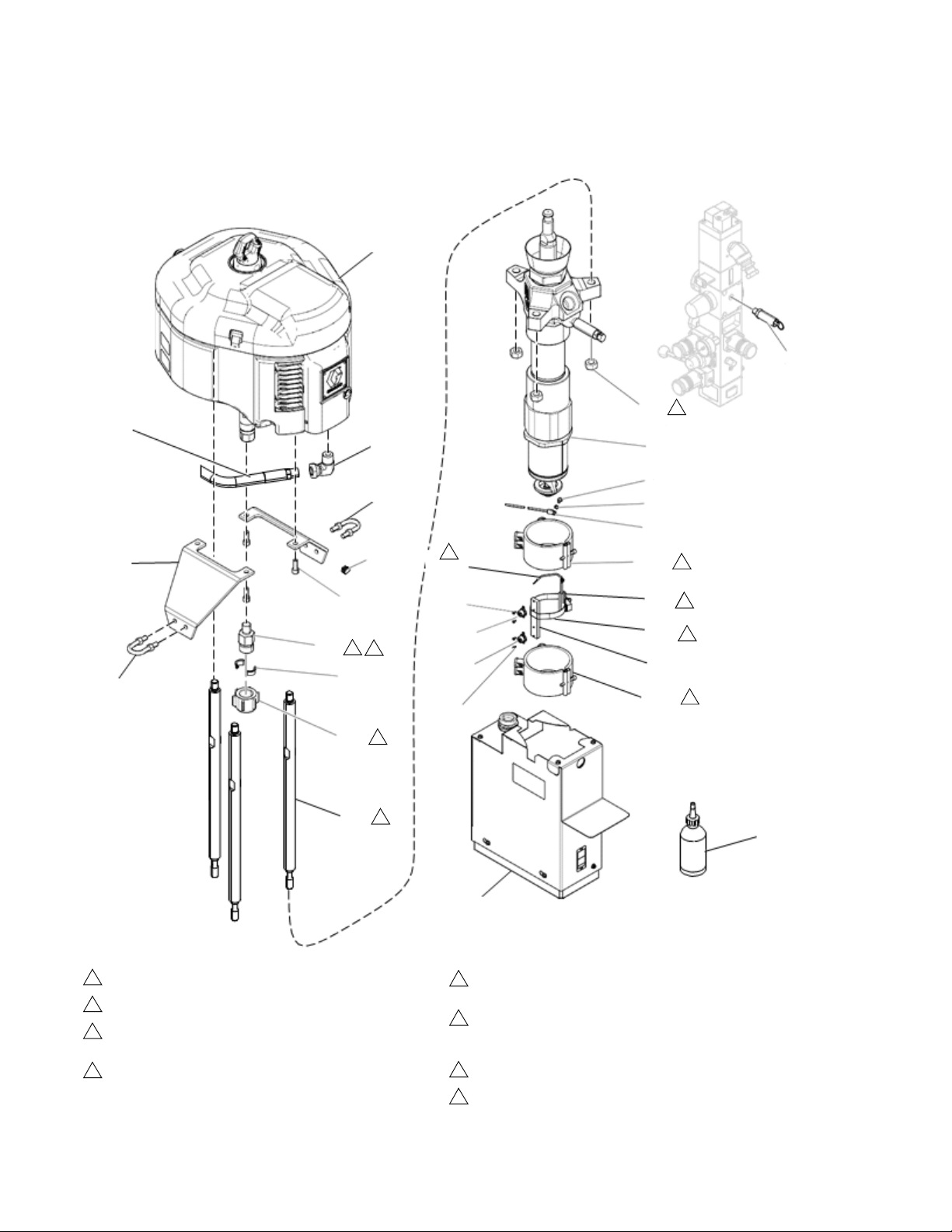
Parts
Torque to 50-60 ft-lbs (68-81 N•m).
Torque to 145-155 ft-lbs (196-210 N•m).
Coat mounting surface of sensor mounting block (411) with
non-silicone heat sink compound. Do not coat sensor.
Prior to tightening band clamp (412), RTD sensor (410)
must be fully contained within the sensor mount (411).
123
4
After fastening band clamp (412), secure excess with
fiberglass tape.
Coat inside of heater (407) only to within 0.75 in. (19 mm)
of vertical ends with non-silicone heat sink compound
before mounting.
Torque to 150 ft-lb (203 N•m).
Apply anaerobic sealant to threads.
568
10
401
402
418
423
409
404
414
413
405
422
433
403
418
406
424
408
417
415
416
407a
411
412
429
407b
410
431
430a
430b
431
428
ti25160a
1
2
8
10
4
6
5
3
6
1
NXT 6500, 70:1 Pump Modules
82 334130T
Page 83

NXT 6500, 70:1 Pump Modules
Ref Part Description Qty
401 N65LR0
402 120375
403 15H542
404 17A406 ADAPTER, rod, pump, tof 1
405 16A223
406 106166 NUT, mach, hex 3
407 128322
408 24W150
24W151
409 C19837
410 24Z093
411 C03507 SUPPORT, sensor 1
412 C31012 CLAMP 1
413 186925
414 184129
415 C38163
416 --- CONDUCTOR, ground 1
417 C38162 SCREW, machine 1
418 120186
419 100307
422 ---
423 120588 PLUG, pipe, round 1
424 120012 VALVE, safety, 50 psi 1
425 ---
426 C33049
428 206994 FLUID, tsl 8 oz bottle 1
429 17B715
430 127671
431 122338
432 17C255
433 ---
MOTOR, 6500, low-noise, remote
ADAPTER, elbow, 3/4 npti x 1/2
npte
BRACKET, mounting, motor,
tof200
ROD, tie, vert driver
HEATER, pump, 600 watt
PUMP, long shaft, cf; 24V005 only
PUMP, long shaft, gf; 24V008 only
SCREW, cap, socket hd
SENSOR, RTD
NUT, coupling
COLLAR, coupling
WASHER, lock, ext. tooth
BOLT, mounting, u-bolt
NUT, hex
SHIELD, pump, tof200; see
24V619, Pump Shield, page 84
LUBRICANT, high temp, thermal
TAPE, adhesive, fiberglass
SUPPORT, block, overtemp
SWITCH, over temp, fixed, 450°F
(232°C)
SCREW, cap, socket bh
CABLE, M12, 8p, 5p, m, 0.2 m
HOSE, coupled, 13.5 ft (4 m)
1.5
Parts
1
1
2
3
2
1
1
4
1
1
2
1
2
4
1
1
1
2
4
1
1
334130T 83
Page 84
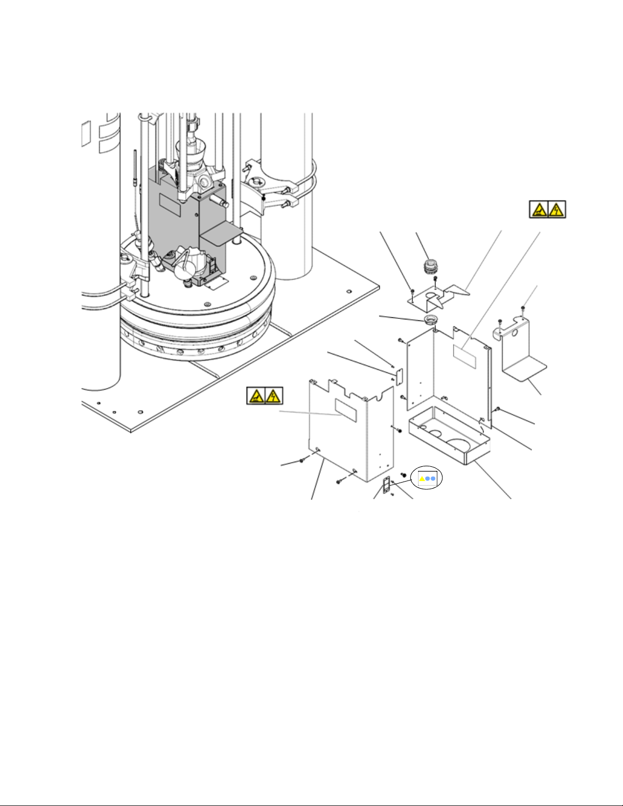
Parts
506
510 505
509
506
504
506
502
501
508
507
503
506
509
507
508
511
ti25162a
24V619, Pump Shield
Ref Part Description Qty
500 24V619PKG
501* --502* --503* --504* --- COVER, pump, top, front 1
505* --506* ---
84 334130T
SHIELD, pump, TOF200
COVER, pump, bottom
COVER, pump, right
COVER, pump, left
COVER, pump, top, back
FASTENER, thread-cutting
screw
1
1
1
1
12
Ref Part Description Qty
507*▲ 17J504
508* 104088
509*▲ 15J075
510 --511 C20731
▲ Replacement Warning labels, signs, tags, and cards
are available at no cost.
* Parts included in Kit 24V619PKG.
LABEL, warning
RIVET, blind
LABEL, safety, hot surface
and shock
BUSHING, conduit, 1 in
FITTING, conduit, connector,
1 in.
2
4
2
1
1
Page 85
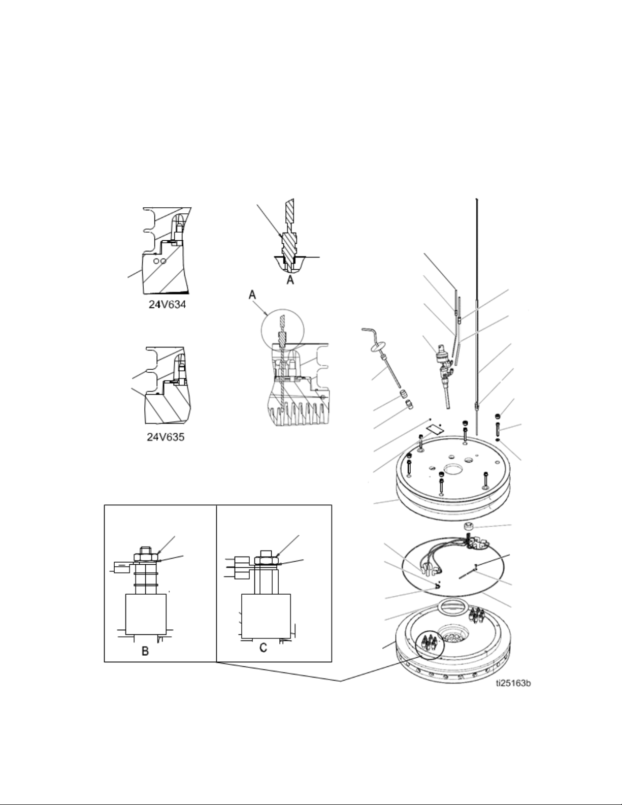
Heated Platens
601
605
601
609
608
607
615
614
603
627
624
623
606
601
622
604
619
602
612
613
605
609
625
628
610
626
629
630
611, 629
24V633, Heated Drum Platen, Mega-Flo (Code E-option M) 24V634, Heated Drum Platen, Standard Grid (Code E-option F) 24V635, Heated Drum Platen, Smooth Bottom (no fin) (Code Eoption S)
Parts
334130T 85
Page 86

Parts
Heated Platens
24V633, Heated Drum Platen, Mega-Flo (Code E-option M) 24V634, Heated Drum Platen, Standard Grid (Code E-option F) 24V635, Heated Drum Platen, Smooth Bottom (no fin) (Code Eoption S)
Ref Part Description Qty
601 --602 C32204 PACKING, o-ring 1
603 15G967 PLATE, tire 1
604 C19049
605 24Z095 SENSOR, temperature 1
606 C32201 GASKET, follower 1
607 158491
608 158581 COUPLING, hex 1
609 617227
610 246501
611 100361 PLUG, pipe 4
612 100133 WASHER, lock 6
613 C19846 SCREW, cap socket, HD 6
614 150707
--615 100508
616 --617 ---
PLATEN — see table below
SCREW, mach, slotted, RND HD
FITTING, nipple
HANDLE, follower, bleed
VALVE, blow off
PLATE, designation
PLATE, designation; 24V633 only
SCREW, drive
CONDUCTOR, 14.2 ft (4.3 m)
CONDUCTOR, 1.7 ft (0.5 m)
1
1
1
1
1
1
1
2
6
2
Ref Part Description Qty
618 --619 --620 112901 NUT, hex 12
621 111640 WASHER, lock, internal 12
622 --- PLUG, follower, plate 1
623 127671
624 122338
625 --- TUBE, ptfe, 1/4 X 5/16 3
626 --- TUBE, ptfe, 3/32 X 5/32 3
627 ---
628 127690
629 127689
630 ---
CONDUCTOR, 0.3 ft (0.09 m)
CONDUCTOR, ground
SWITCH, over temp, fixed, 450°F
(232°C)
SCREW, cap, socket bh
SLEEVE, fiberglass, hi-temp
FITTING, adapter, 5/16 in. tube x
1/4 in tube
FITTING, adapter, 1/4 in tube x
5/32 in tube
TUBE, polyeth, 1/4 OD; 26 ft (7.9
m)
4
1
1
2
3
1
1
1
Platen Model Description Ref. No. 601 Qty. Element Resistance
24V633 Mega-Flo 194254 1 16.5 ohms +1/-2
24V634 Standard Grid 617225 1 19.2 ohms +2/-3
24V635 Smooth Bottom C57358 1 19.2 ohms +2/-3
86 334130T
Page 87
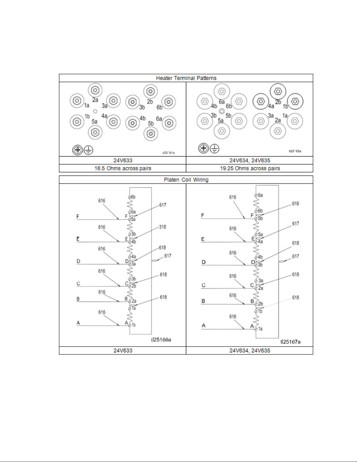
Parts
334130T 87
Page 88
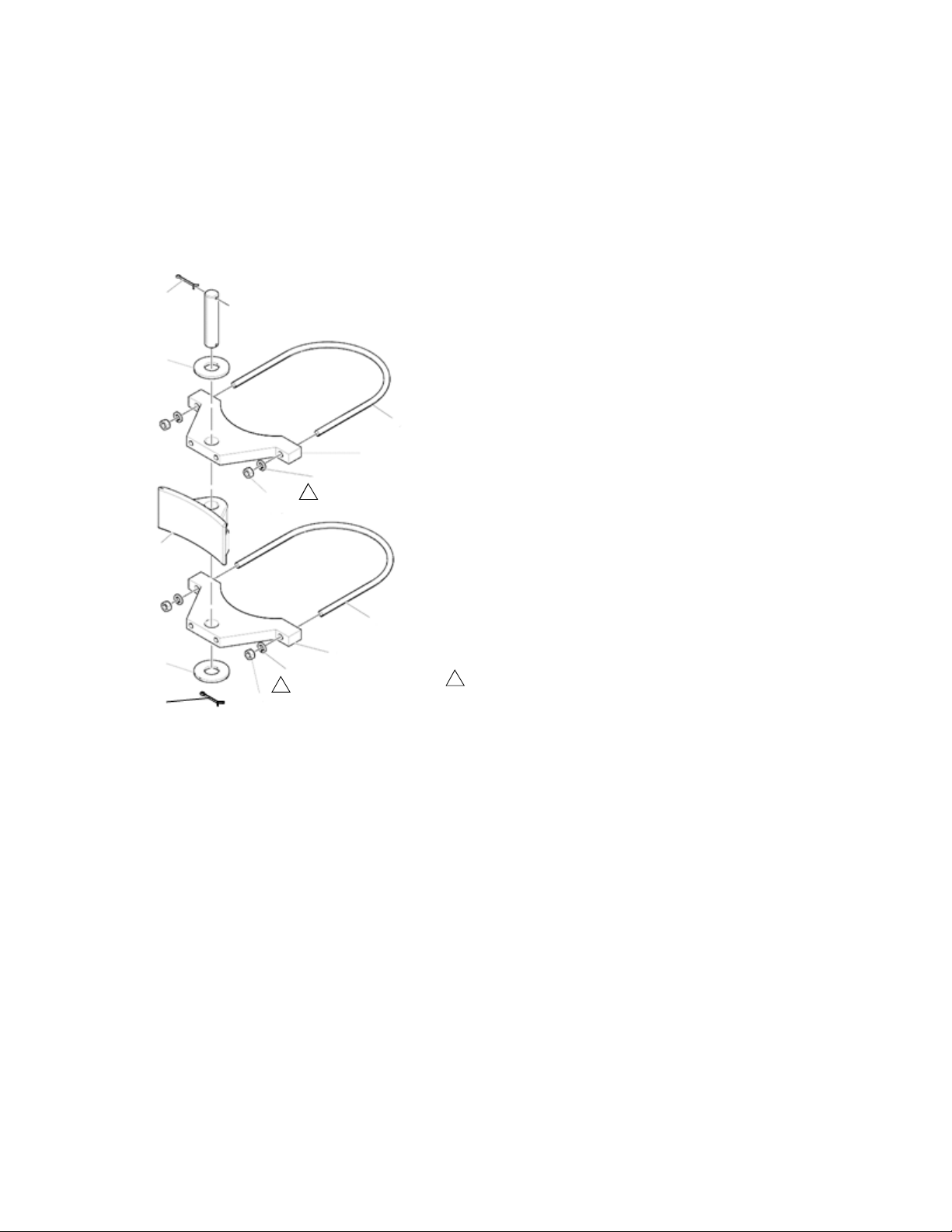
Parts
703
706
701
707
705
704
701
707
705
704708
706
702
1
1
ti25188a
Torque to 50 in-lbs.
1
Drum Ram Post Saddle Clamp
C32463
Option H-1
Ref Part Description Qty
701 C32424
702 160111
703 100103
704 100307 NUT, hex 4
705 100133
706 C38182
707 C32461
708 166265
88 334130T
BOLT, U, 7 in. (177.8 mm)
CLAMP, barrel
PIN, cotter
WASHER, lock
WASHER, plain
CLAMP, saddle
PIN, pivot
2
1
2
4
2
2
1
Page 89
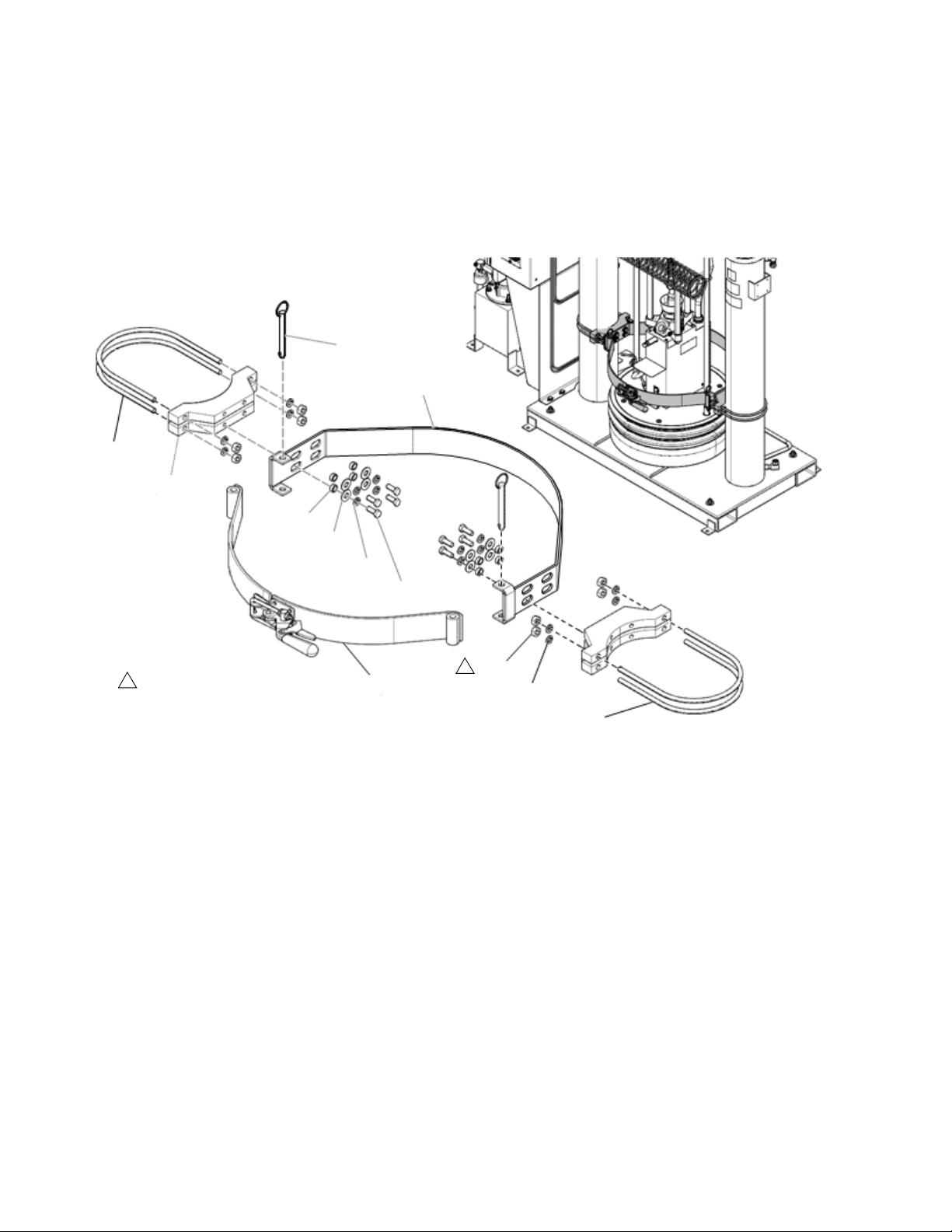
Drum Ram Post Saddle Clamp
751
759
708
707
706
702
704
710
756
761
703
705
ti25189a
Torque to 50 in-lbs.
1
1
918395
Option H-3
Parts
Ref Part Description Qty
702 100101
703 918421
704 918423
705 617395 PIN, quick release 2
756 100133
707 C19200
708 617433
759 617395
710 100131
761 C32424
334130T 89
SCREW, cap, hex hd
CLAMP, back half assembly
KIT, repair
WASHER, lock
WASHER, plain
SPACER, drum clamp
CLAMP, saddle
NUT, full hex
BOLT, U 7 in. (177.8 mm)
8
1
1
8
8
8
4
8
4
Page 90
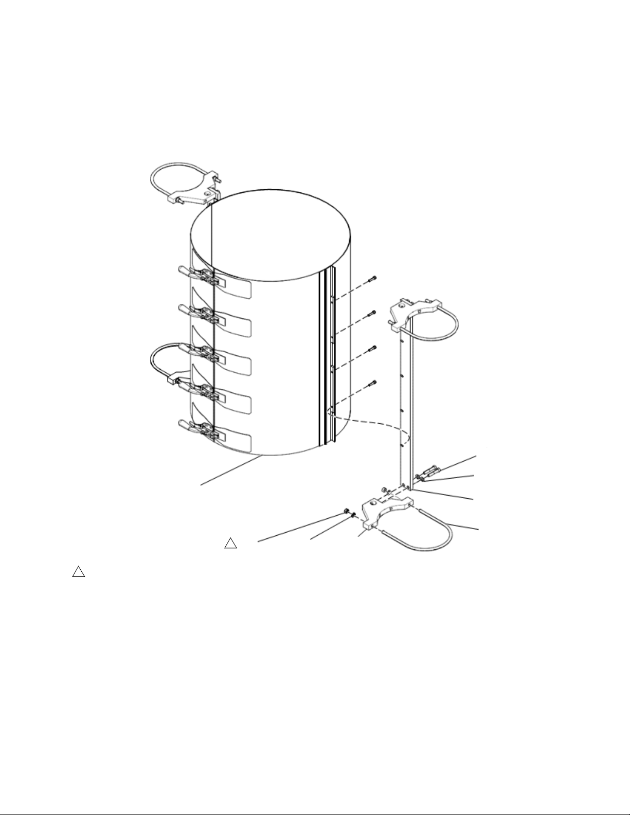
Parts
ti25190a
801
804
803
805
6
807
803
802
1
Torque to 50 in-lbs.
1
Fiber Drum Reinforcement Shell Clamp
918397
Option H-2
Ref Part Description Qty
6 C32424
801 C32271
802 C19126
803 100133 WASHER, lock 12
804 100307
805 617340
807 617341
BOLT, U, 7 in. (177.8 mm)
CLAMSHELL
SCREW, cap, hex hd
NUT, hex
CLAMP, saddle
MOUNT, clam shell
4
1
8
8
4
2
90 334130T
Page 91
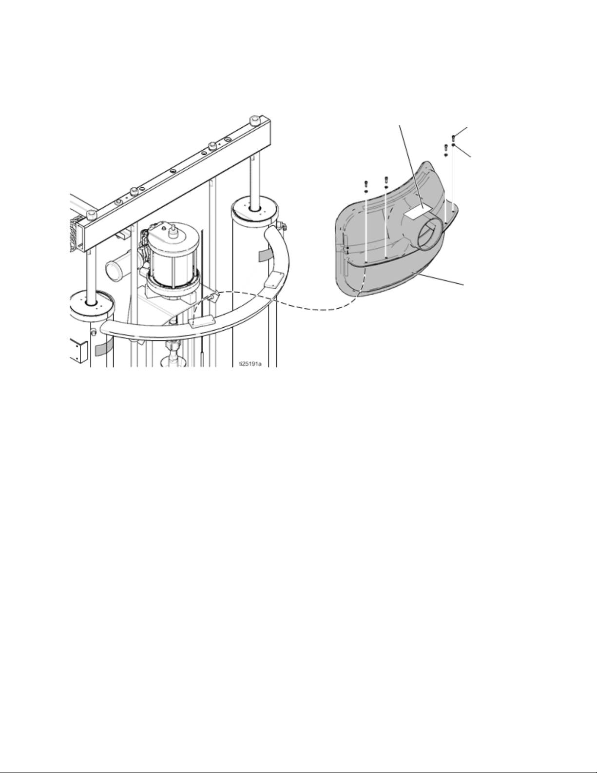
Vent Hood Kit, 233559
855
852
853
851
Parts
Ref Part Description Qty
851 --852 112166
853 100016
855▲ C14038 LABEL, warning 1
VENT hood
SCREW, cap, sch
WASHER, lock
1
4
4
▲ Replacement Warning labels, signs, tags, and cards
are available at no cost.
334130T 91
Page 92

Accessories and Kits
Accessories and Kits
Wiper Kits
See manual 309196 for installation and repair instruc-
tions.
Part No. Description
253291 Hose/Spring Wiper Kit
253290 Hose and T-Wiper Kit
253289 Twin Hose Wiper Kit
253292 T-Wiper Kit
Applicators and Dispense Valves
Part No. Description
249515 Manual Gun, Top Feed, 240V
249514 Manual Gun, Bottom Feed, 240V
249513
249512
Manual Gun, Top Feed, Electric Switch,
240V
Manual Gun, Bottom Feed, Electric Switch,
240V
Air-Operated Heated Dispense
Valves
Part No. Description
243694
244951
244909
243701
Automatic Dispense Valve, 240V,
Air-Operated Heated Dispense Valve
Automatic Endure Dispense Valve, 240V,
Air-Operated High Flow Heated Dispense
Valve
Automatic Endure Dispense Valve, 240V,
Air-Operated Snuff-Back Heated Dispense
Valve
45 in (114 cm) Distribution Header With
Valve, 240V
CGM Installation Kit, 25C994
This kit enables controlling logic, such as a robot con-
troller or PLC continuously monitoring data from the
Therm-O-Flow system, as well as optionally controlling
the system accordingly. Refer to manual 3A5186 for
details on the interface. When ordering this kit, select
and order the correct communication gateway module
(CGM) that matches the field bus being used. The fol-
lowing CGM modules are available for the
Therm-O-Flow system.
Part No. Description
CGMEP0 EitherNet/IP
CGMDN0 DeviceNet
CGMPB0 ProfiBus
CGMPN0 ProfiNet
Flow Control and Manifolds
Part No. Description
243700
243656
243657
243697
289208 Compact Heated Regulator
Heated Air Operated Mastic Pressure
Regulator, 240V
23:1 Heated Pressure Compensator Valve,
240V
51:1 Heated Pressure Compensator Valve,
240V
Heated Distribution Manifold, 240V
Includes (2) 3/4 npt(f) inlet check valves, (1)
npt 4–ported manifold, (2) 1 in npt(f) outlet
gate valves, mounting bracket, 400w 230
VAC heaters, RTD sensor, and 8 pin
connector box.
92 334130T
Page 93

Accessories and Kits
Accessory Extension Cables
Use to connect fluid control devices and heated hoses to
the electrical control enclosure.
Part No. Description
Connect between controller and heated hose
129300 15 ft, 12 pin to 12 pin
129301 25 ft, 12 pin to 12 pin
Connect between controller and heated accessory
129302 15 ft, 12 pin to 8 pin
129303 25 ft, 12 pin to 8 pin
Connect between controller and heated devices
129703 25 ft, 12 pin to (2) 8 pin
129304 50 ft, 12 pin to (2) 8 pin
Connect between two heated devices
15C294 30 ft, 8 pin to 8 pin
Light Tower Kit, 24W589
Tie Rod Kits
Use to retrofit Check-Mate 800 Displacement Pump to an
existing Therm-O-Flow system.
Part No. Description
24V750
24V754 NXT® Tie Rod Kit; see manual 334132
Bulldog® and Senator® Tie Rod Kit; see
manual 334131
334130T 93
Page 94
Accessories and Kits
Heated Hoses and Fittings
NOTE: Refer to Heated Hose, Instructions-Parts man-
ual 3A4241 for additional information about heated
hoses. See Related Manuals on page 8.
-6
(9/16 in -18
Hose Diameter
Hose Length
3 ft (1 m) None None None 19M410 None None
4 ft (1.2 m) None 19M400 None None None None
6 ft (1.8 m) None 19M401 19M404 19M411 19M416 None
10 ft (3 m) 19M423 19M402 19M405 19M412 19M417 19M421
15 ft (4.6 m) None 19M403 19M406 19M413 19M418 19M422
20 ft (6 m) None None 19M407 19M414 19M419 None
25 ft (7.6 m) None None 19M408 19M415 19M420 None
30 ft (9 m) None None 19M409 None None None
Pump Fittings
TOF 20/200 PUMP
1-11 1/2 DUAL
OUTLET ADD
120263
TOF MINI 5 PUMP
1/2 NPT DUAL
OUTLET ADD
120241
Hose to Hose Fittings
-6 Hose (.308 ID) 125779 123684 123683
-8 Hose (.401 ID) 123684 120241 120242 120244
-10 Hose (.495 ID) 123683 120242 120243 120246
-12 Hose (.617 ID)
-16 Hose (.687 ID)
-20 Hose (1.125 ID) None
Fittings
Compensator 51:1,
243657
Compensator 23:1,
243656 Inlet &
Outlet: 1-11 1/2 in
NPTF
JIC)
16V432
100380
16V432 C20678 C20679 C38006 158586
123683
120265
123683
120265
120267
16V432
100380
-8
(3/4 in -16
JIC)
253267 253268 120260 120261 120262
120244 120246 120247 120248
120244
120267
6308-82
126521
6308-82
-10
(7/8 in -14
JIC)
120246
120267
120246
120267
120268
123135
120266
-12
(1-1/16 in -12
JIC)
123683
120265
120248 120249
123135
126521
123135 123854
-16
(1-5/16 in -12
JIC)
-20
(1-5/8 in -12
JIC)
123683
120265
120267
120244
120267
120246
120267
120249
120268
120804
120268
None
6308-82
126521
6308-82
126521
123135
126521
120249
120268
120250
15D936
94 334130T
Page 95

Accessories and Kits
Hose Diameter
Distribution manifold,
243697 Inlet: 3/4 in
NPTF
Distribution manifold,
243697 Outlet: 1-11
1/2 in NPTF
Compact Heated
Regulator, 289208
Inlet & Outlet: 3/8 in
NPTF
Mastic Regulator,
243700 Inlet &
Outlet: 3/4 in NPTF
Top and bottom feed
guns with and
without switch,
249512, 249513,
249514, 249515
Inlet: 7/8-14 (JIC
-10) male
Standard, High Flow
& Snuff-back
Dispense valves,
243694, 244951,
244909 Inlet: 1/2
NPTF
Distribution header,
243701 Inlet: 1/2
NPTF
Precision Gear
Meter PGM Inlet:
1-5/16-12 o-ring face
seal
Precision Gear
Meter PGM Outlet:
3/4 NPTF
PCF Metering
System Inlet &
Outlet: 3/4 NTPF
-6
(9/16 in -18
JIC)
16V432
100896
16V432
100380
16V432
100896
16V432
100896
117677
16V432
16V432
None
16V432
100896
16V432
100896
-8
(3/4 in -16
JIC)
-10
(7/8 in -14
JIC)
-12
(1-1/16 in -12
JIC)
-16
(1-5/16 in -12
JIC)
124286 15Y934 C20708 125661
6308-82
123135
120266
123135 123854
121311 116765 116766
124286 15Y934 C20708 125661
120264 None 120265 None
124287 C20768 94/1027/99 125662
124287 C20768 94/1027/99 125662
None None 124238 124239
124286 15Y934 C20708 125661
124286 15Y934 C20708 125661
116766
120267
-20
(1-5/8 in -12
JIC)
125661
120268
15D936
116766
120267
120268
125661
120268
None
125662
120268
125662
120268
124240
125661
120268
125661
120268
334130T 95
Page 96
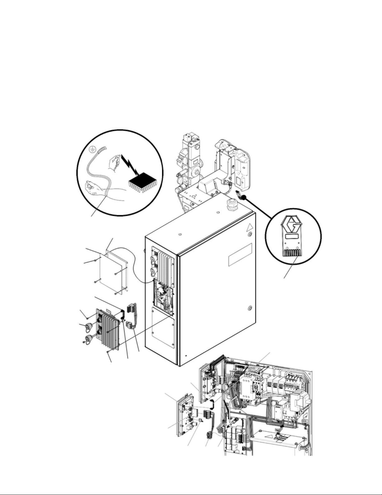
Accessories and Kits
ti25236b
7
C
A
B
4
2
3
B
5
6
8
4
J3
J6
J2
5
6J5
8 Channel Upgrade Kit, 24V755
Use this kit to upgrade a 4 Channel system to an 8 channel system.
Ref Part Description Qty
1 --- MODULE, GCA, MZLP 1
2 125856 SCREW, 8–32, serrated flange 4
3 16T440 CAP, souriau, UTS14 2
4 127511 CABLE, board, samtec 1
Ref Part Description Qty
5 16W035 CONNECTOR, jumper 1
6 17A544 HARNESS, power, MZLP2, AWB 1
7 112190 STRAP, wrist, grounding 1
8 17C712 TOKEN, software upgrade 1
96 334130T
Page 97

8 Zone Upgrade Kit Installation
1. Disconnect the plug from the power outlet or turn off
the circuit breaker for incoming power.
2. Place the grounding wrist strap (7) over your wrist
and secure the other end to a grounded surface.
3. Set the kit’s MZLP (1) rotary switch to “2” on a pri-
mary system or “6” on a secondary system.
4. Remove the screws (B), the plate (A), and the gas-
ket (C) from the system. Use the screws (2) to install
the MZLP (1) onto the system as shown.
NOTE: The new MZLP (1) will be refereed to as MZLP2,
and the original MZLP that came with the system will be
referred to as MZLP 1.
Accessories and Kits
5. Open the Electrical Enclosure door.
NOTE: Do not force the electrical connection. Minimal
force is required to seat the connector. If resistance is
felt, stop, and verify the connector orientation.
6. Connect the cable (4) to the J3 connector on MZLP
1 and the J6 connector on MZLP 2.
7. Connect the power harness (6) to the MZLP 2 J2
connector and the J5 connector on the AWB. Install
the jumper (5) on the MZLP 2 J5 connector.
8. Use fittings and hoses that meet your hose routing
needs. See Accessories and Kits, page 92.
9. To ensure your system has the latest software,
insert the token (8) into the ADM. See Update Soft-
ware, page 61.
334130T 97
Page 98
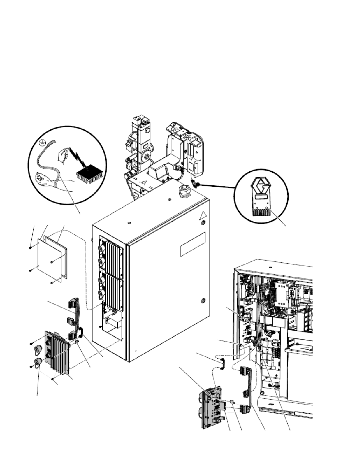
Accessories and Kits
ti25237b
B
A
C
2
1
5
4
J3
4
J6
J2
8
6
J5
5
J2
7
6
3
12 Channel Upgrade Kit, 24V756
Use this kit to upgrade an 8 channel system to a 12 channel system.
Ref Part Description Qty
1 --- MODULE, GCA, MZLP 1
2 125856 SCREW, 8–32, serrated flange 4
3 16T440 CAP, souriau, UTS14 2
4 127511 CABLE, board, samtec 1
5 16W035 CONNECTOR, jumper 1
Ref Part Description Qty
6 17A545 HARNESS, power, MZLP2/3,
AWB
7 112190 STRAP, wrist, grounding 1
8 17C712 TOKEN, software upgrade 1
1
98 334130T
Page 99

12 Zone Upgrade Kit Installation
1. Disconnect the plug from the power outlet or turn off
the circuit breaker for incoming power.
2. Place the grounding wrist strap (7) over your wrist
and secure the other end to a grounded surface.
3. Set the kit’s MZLP (1) rotary switch to “3” on a pri-
mary system or “7” on a secondary system.
4. Remove the screws (B), plate (A), and the gasket
(C) from the system. Use the screws (2) to install
the MZLP (1) on to the system as shown.
NOTE: The new MZLP (1) will be referred to as MZLP 3,
and the other two that came with the system will be
referred to as MZLP 1 and MZLP 2.
Accessories and Kits
5. Open the Electrical Enclosure door.
NOTE: Do not force the electrical connection. Minimal
force is required to seat the connector. If resistance is
felt, stop, and verify the connector orientation.
6. Connect the cable (4) to the J3 connector on MZLP
2 and the J6 connector on MZLP (1). Remove the
existing power cable from MZLP 2 J2 and AWB J5
connector.
7. Connect the power harness (6) to MZLP 2 and the
MZLP 3 J2 connector and the J5 connector on the
AWB.
8. See Install Heated Hose, page 18, to connect a
heated hose or fluid control device.
9. To ensure your system has the latest software,
insert the token (8) into the ADM. See Update Soft-
ware, page 61.
334130T 99
Page 100

Appendix A - ADM
Appendix A - ADM
General Operation
ADM Power
The ADM automatically turns on when the Main Power
Switch is turned on.
Screen Navigation
To switch between the Setup and Operation screens,
press . Use the keypad to navigate between
screens.
Enable, Disable Heating System
To enable or disable the entire heating system, press
. To set which channels are active when the heat-
ing system is enabled, use the Heat-A and Heat-B
Setup screens.
100 334130T
 Loading...