

Graco TexSpray RTX 750, TexSpray RTX 1000 Repair Manual
Repair
S
C
Interior Texture Sprayers
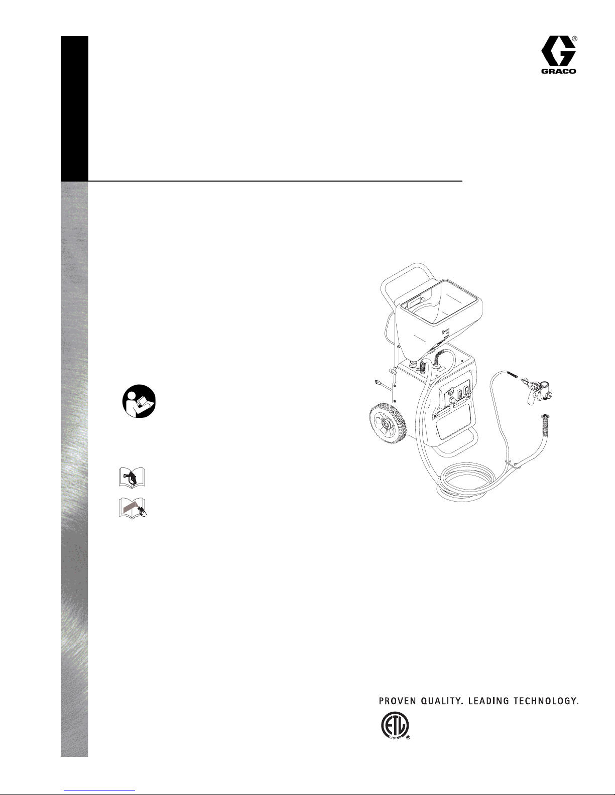
TexSpray™ RTX 750™
and RTX 1000™
U.S. patent D526,045
For Water-Based Materials Only
Models:
246183 - RTX 750, 6 Gallon
55 psi (0.379 MPa, 3.79 bar)
Maximum Fluid Working Pressure
246184 - RTX 1000, 8 Gallon
60 psi (0.414 MPa, 4.14 bar)
Maximum Fluid Working Pressure
Important Safety Instructions
Read all warnings and instructions in this manual.
Save these instructions.
Related Manuals
309586R
309584
309585
U.S. patent D501,241
Graco Inc. P.O. Box 1441 Minneapolis, MN 55440-1441
www.graco.com
Copyright 2003
Graco Inc. is registered to I.S. EN ISO 9001
Model 246184 Shown
U
Conforms to ANSI/UL
standard 1450

WARNINGS
Fire and Explosion Hazard
Improper grounding, poor ventilation, open flames or sparks can cause a hazardous condition and result
in fire or explosion and serious injury.
• The system is for use with water-based materials only. Only use fluids compatible with the
equipment. Refer to Technical Data of all equipment manuals. Read fluid and solvent manufacturers
warnings.
• Ground all equipment in the work area. See Grounding and Electrical Requirements, page 5.
• If there is any static sparking or you feel an electric shock while using this equipment, stop spraying
immediately. Do not use the equipment until you identify and correct the equipment until you identify
and correct the problem.
• Keep work area free of debris, including solvent, rags and gasoline.
• Comply with all applicable state and national fire, electrical and safety regulations.
• Keep a fire extinguisher in the work area.
Equipment Misuse Hazard
Equipment misuse can cause equipment to rupture, malfunction, or start unexpectedly and cause
serious injury.
• Before operating this equipment, read all manuals, tags, and labels, including material labels and
instructions.
• Do not expose system to rain. Always store system indoors.
• Do not alter or modify equipment.
• Do not spray cementicious materials.
• Do not exceed maximum working pressure of lowest rated component in your system.
• Check equipment daily. Repair or replace worn or damaged parts immediately.
• To reduce risk of serious injury, including electric shock and splashing fluid in eyes, follow Pressure
Relief Procedure on page 5 before servicing the unit.
• Do not kink or over bend hoses or use hoses to pull equipment.
• Route hoses away from traffic areas, sharp edges, moving parts and hot surfaces. Do not expose
Graco hoses to temperatures above 130 F (55 C) or below -35 F (-37 C).
• Air hoses at the compressor end, can get very hot! Allow sprayer to cool down 15 minutes before
removing air hose.
• Store hazardous fluid in an approved container. Dispose of hazardous fluid according to all local,
state and national guidelines.
• Never directly inhale compressed air. Compressed air may contain toxic vapors.
2 309586R
WARNINGS
Electric Shock Hazard
To reduce the risk of electric shock:
• Be sure sprayer is adequately grounded through electrical outlet, page 5.
• Use only 3-wire, extension cords.
• Make sure ground prongs are intact on sprayer and extension cords.
• Do not operate with cover removed.
• Turn off sprayer. Follow Pressure Relief Procedure, page 5, and unplug unit, before removing any
parts.
Pressurized Equipment Hazard
Fluid from gun, leaks or ruptured components can splash in the eyes or on skin and cause serious injury.
• Follow Pressure Relief Procedure, page 5 when you stop spraying and before cleaning, checking
or servicing.
• Do not point spray gun at anyone; put hand, fingers or rag over nozzle, or stop or deflect leaks with
your hand, body, glove, or rag.
• Wear protective clothing, gloves, and eyewear.
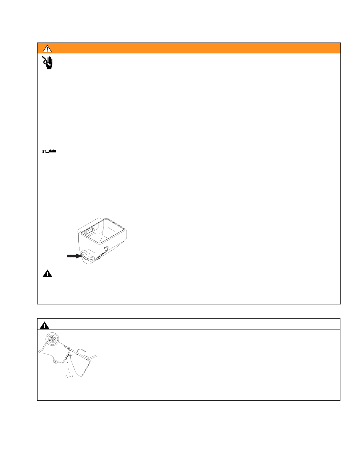
• Before adding material to hopper, install burp guard. When only a small
amount of material remains in the hopper, the burp guard prevents material
from shooting out when the unit is turned off. This material could splash in
the operator’s eyes or on skin, or into the air.
ti2894a
Cleaning Solvent Hazard with Plastic Parts
Use only compatible water-based solvents to clean plastic structural or pressure-containing parts. Many
solvents can degrade plastic parts to the point where they could fail. Such failure could cause serious
injury or property damage. See Technical Data on page 26 of this instruction manual and in all other
equipment manuals. Read fluid and solvent manufacturer’s warnings.
CAUTION
Water or material remaining in unit when temperatures are below freezing can damage
motor and/or delay pump startup.
To insure water and material are completely drained out of unit:
1. Remove material line from sprayer.
ti2754a
2. Tip sprayer up as shown.
Before adding material or starting unit in cold weather, run warm water through pump.
309586R 3
Component Identification
Component Identification
M
aa
P
Y
B
A
L
C
G
K
N
H
D
W
E
J
F
T
cc
bb
dd
S
U
R
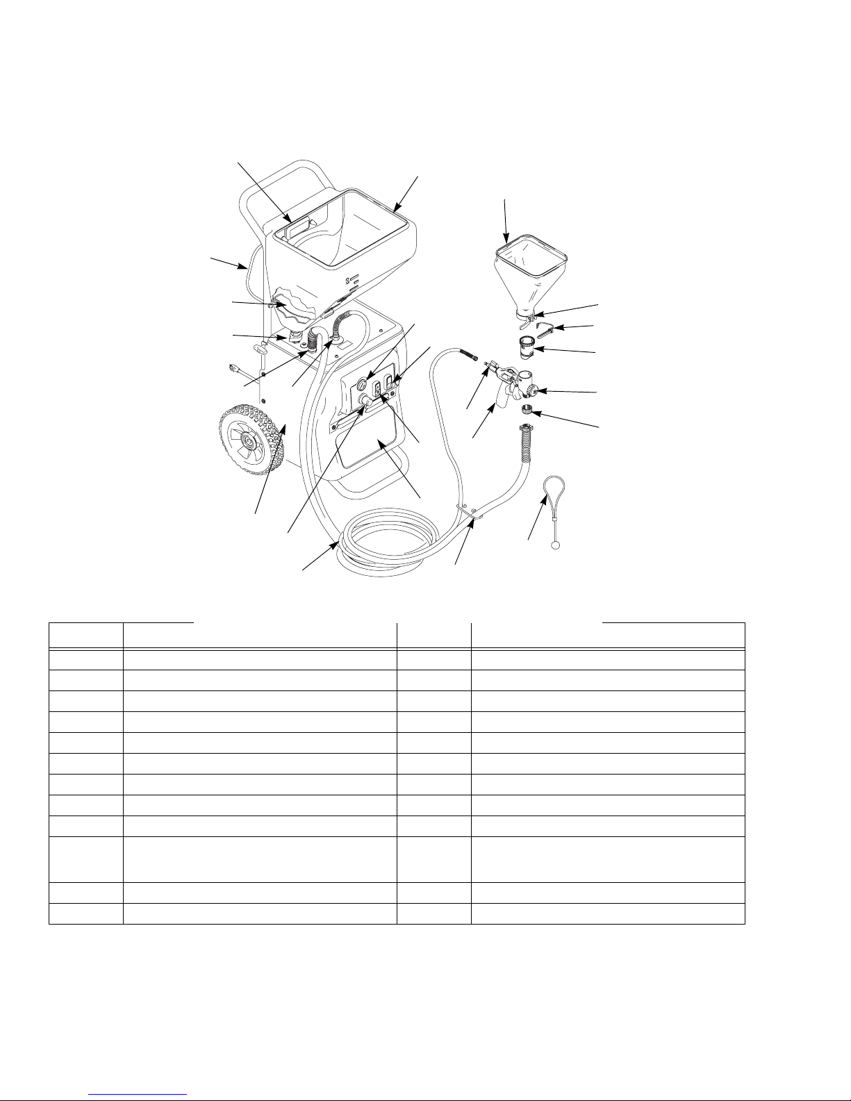
Item Component Item Component
A Air hose outlet N Touch-up hopper (3/4 gallon)
B Material hose outlet P Nozzle storage
C Material flow control (RTX 1000) R Hose plug
D Hopper gun/spray gun selector switch S Gun plug
E ON/OFF switch T Material thickness gauge
F Air Compressor (inside) U Nozzle
G Material/air hose W Gun air valve
H Material flow indicator (RTX 1000) Y Burp guard
J Texture spray gun (manual 309584) aa Hopper fitting (fluid inlet)
K Material Hopper - 6 gallon, RTX 750
Material Hopper - 8 gallon, RTX 1000
L RotoFlex™ pump (inside) cc Hose clip
M Hose rack/cord wrap dd Gun plug clip
bb Hopper clamp
4 309586R
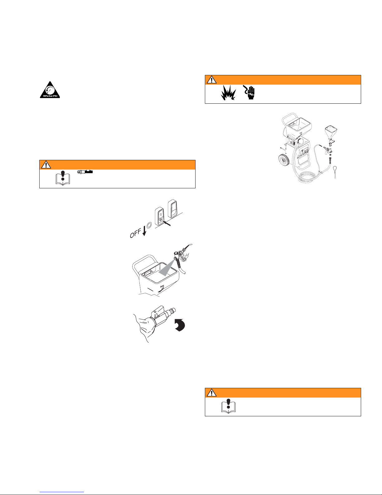
Pressure Relief Procedure
To reduce risk of injury, follow this procedure
whenever you see this symbol throughout this
manual, Also, perform this procedure whenever
you:
• stop spraying.
• check or repair any part of this system.
• install or clean spray nozzle.
WARNING
page 2
Preparation
Preparation
WARNING
page 2
120V AC Systems
• This equipment
requires a 120V
AC, 60 Hz, 15A
circuit with a
grounding
receptacle. Do not
use an adapter
with this product.
Extension Cords
1. Turn Power Switch OFF.
TI2458a
2. Trigger gun into material
hopper.
ti2447a
3. Open gun air valve.
ti2448a
Grounding and Electrical Requirements
This sprayer must be grounded. Grounding reduces the
risk of electrical shock by providing an escape wire for
the electrical current. The sprayer cord includes a
grounding wire with an appropriate grounding plug. The
plug must be plugged into an outlet that is properly
installed and grounded in accordance with all local
codes and ordinances.
• Use only an extension cord with an undamaged,
3-prong plug.
• For 25 to 50 ft (7.6 to 15.2 m) cords, use 3-wire, 14
AWG (1.5 mm
2
) minimum.
• For up to 100 ft. (30.48 m) cord, use 3-wire, 12 AWG
(2.5 mm
2
) minimum.
Auxiliary Air Compressor
Do not use an auxiliary air compressor with this spray
system.
Generator Requirements
3500 W (3.5 KW) minimum.
Hose Size and Length
The system comes with a hose set consisting of a 3/4 in.
ID x 25 ft (25 mm x 7.6 m) material hose and a 3/8 in-ID
air hose.
Do not use more than 25 ft. (7.6 m) of material hose.
WARNING
page 2
Check with a qualified electrician or serviceman if
grounding instructions are not completely understood,
or if in doubt as to whether the product is properly
grounded. Do not modify plug provided; if it will not fit
the outlet, have proper outlet installed by a qualified
electrician.
309586R 5
RotoFlex™ Pump
RotoFlex™ Pump
Disassembly
1. Relieve Pressure, page 5.
2. Unplug sprayer from outlet.
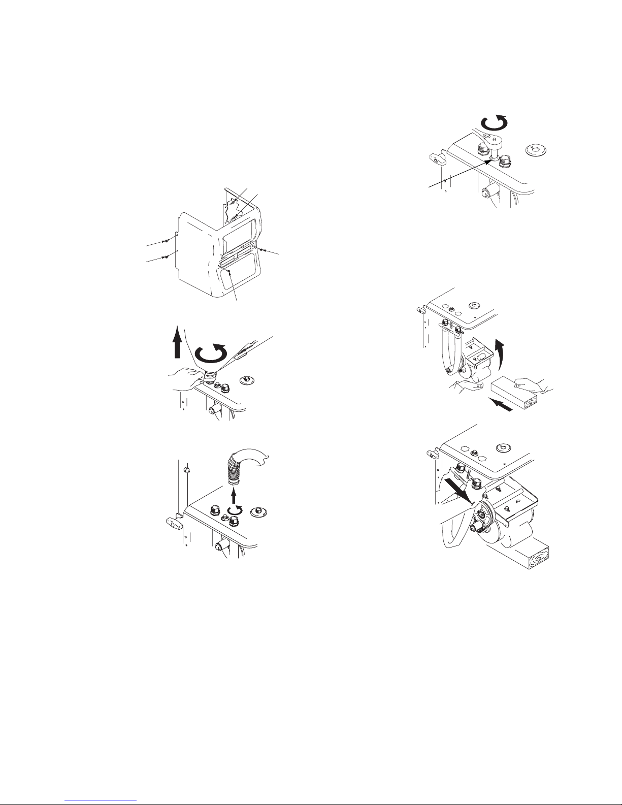
3. Remove shroud
(6 bolts).
1
2
4. Remove hopper by
loosening bottom
fitting and then lifting hopper straight
up, off unit.
ti3025a
6. Loosen bolt (A)
located between air
and material hose
outlets. Unscrew
bolt to lower plate,
6
5
leaving about 4-5
threads on bolt.
A
ti3083a
DO NOT REMOVE
BOLT COMPLETELY.
4
7. Slide a 2 x 4
3
under motor for
support.
ti3124a
5. Remove material
hose.
ti3118a
ti3132a
8. Rotate plate.
Slide hose off by
pushing outward on
hose fitting.
ti3119a
6 309586R
RotoFlex™ Pump
Reassembly
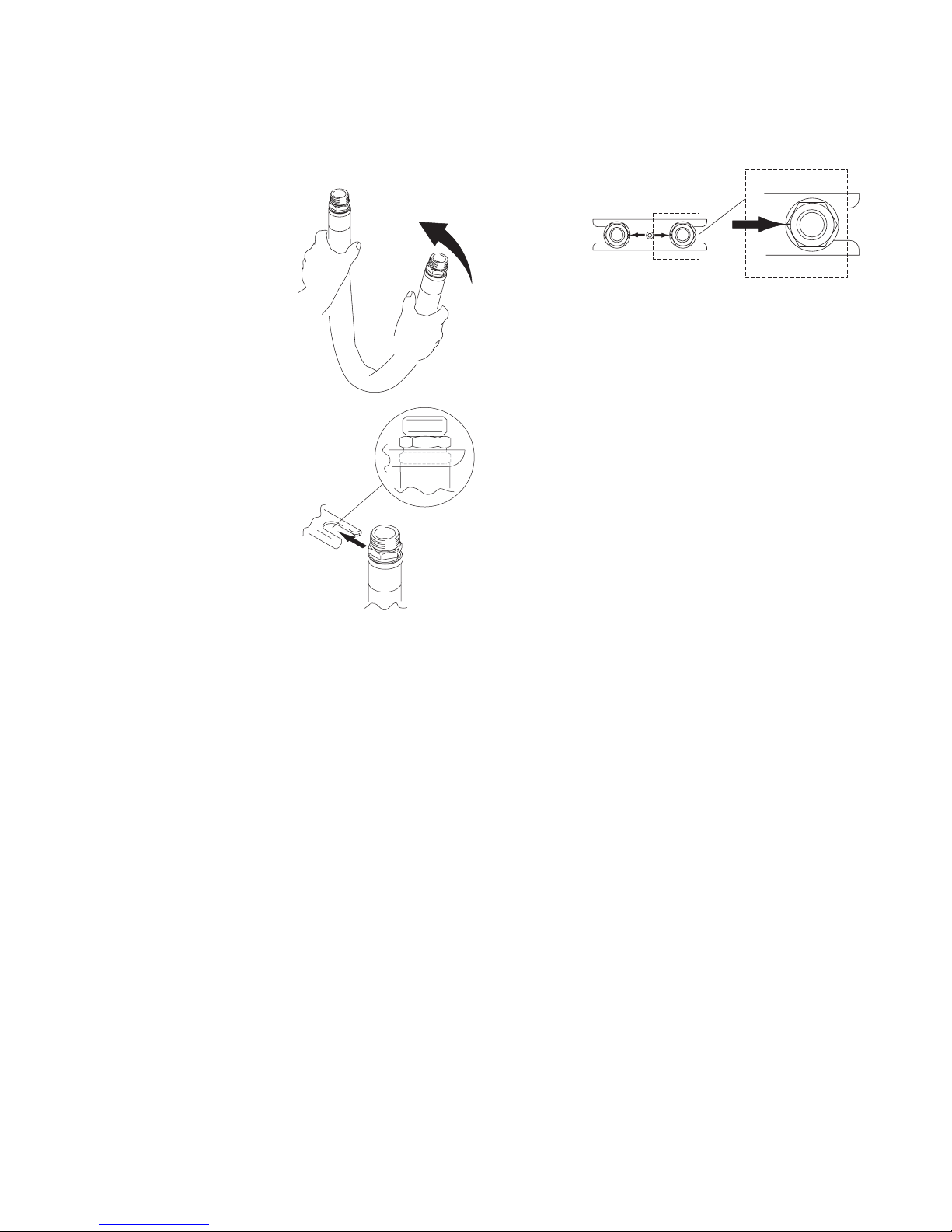
Reinstall RotoFlex Pump hose on plate.
1. Kink hose as shown,
making sure dots
located on hose fitting
face each other.
2. Slide hose onto plate
as shown below, making sure plate slides
into slot between hex
fitting on end of hose.
3. Align dots located on hose fitting, making sure they
are facing each other at all times to ensure the hose
does not twist during reinstallation.
ti3084a
4. Reposition plate, aligning hex fittings with enclosure
openings.
5. Remove 2 x 4 support under motor.
ti3127a
6. Tighten bolt. As bolt is tightened the plate will snug
back into place.
7. Replace shroud (6 bolts).
8. Replace hopper.
9. Break in new pump by running dry or with warm
water for 3-5 minutes.
ti3125a
309586R 7
Compressor Repair
Compressor Repair
Use Compressor Repair Kit, 234211.
Disassembly
1. Relieve Pressure, page 5.
2. Unplug sprayer.
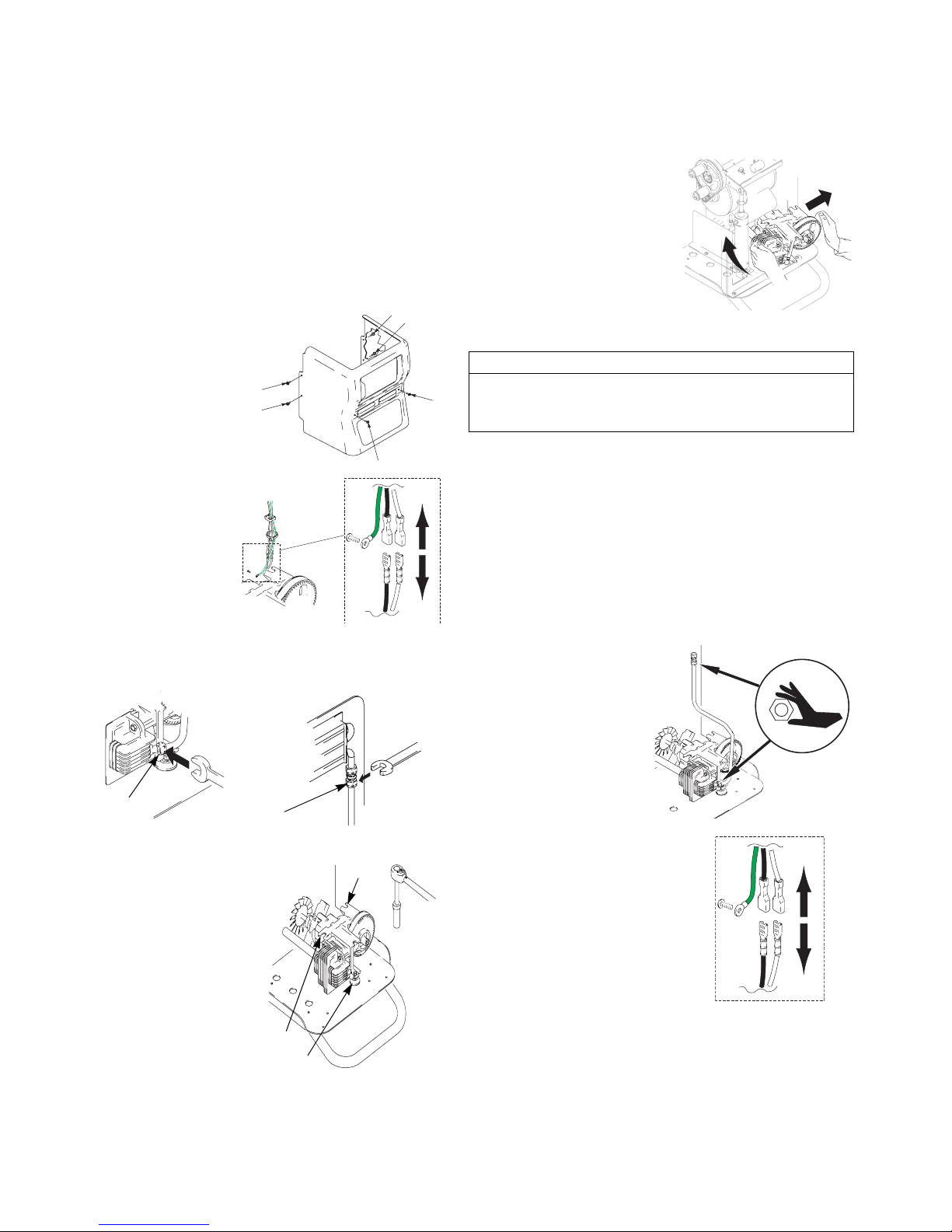
3. Remove shroud (6 bolts).
1
2
4. Remove green
ground wire and
black, and white
wires to compressor.
ti3022a
ti3025a
7. Tilt compressor forward
and remove from housing.
TI3011a
6
5
CAUTION
Fan blades are very delicate and can be damaged very
4
easily. When removing or replacing compressor, do not
bump or jar shroud or fan blades.
3
8. Thoroughly clean inside housing, removing dust and
debris.
Reassembly
1. Carefully position compressor in housing.
2. Replace bolts using socket wrench to tighten.
Torque to 85 in. lbs.
5. Loosen fittings (A and B) and remove air line.
A
6. Using a socket wrench
ti2748a
B
ti2749a
bolt
with extension, loosen
bolts (3).
bolt
bolt
3. Reattach air lines to
compressor. Finger
tighten plus one full
turn, fittings (A and
B).
4. Reattach 3 wires to
compressor matching
green to green, black to
black and white to white.
5. Replace shroud. Tighten bolts (6).
ti3032a
8 309586R
Roller Replacement
Roller Replacement
Use Roller Repair Kit 234214.
Disassembly
1. Relieve Pressure, page 5.
2. Unplug sprayer from outlet
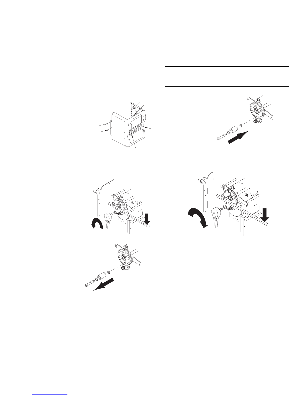
3. Remove shroud (6 bolts).
1
2
4. Remove RotoFlex Pump, page 6.
5. Using a crow bar
as a wedge to
keep rollers from
moving, loosen
shoulder bolt.
ti3025a
Reassembly
CAUTION
When installing bolt through roller, keep nylon washer
on shoulder of bolt.
6
5
3
1. Replace rollers.
ti3030a
4
2. Using a crow bar as a wedge to keep rollers from
moving, torque bolts to 40 ft. lbs.
6. Remove rollers.
ti3026a
ti3031a
ti3029a
3. Reinstall RotoFlex Pump hose on plate, page 6.
4. Replace shroud. Tighten bolts (6).
309586R 9
 Loading...