

Graco GMAX 3400, GMAX II 3900, GMAX II 7900, TexSpray 5900HD, TexSpray 7900HD Operation
...Page 1

Operation
ti23055a
GMAX™ 3400, GMAX™ II 3900/5900/7900, and
3A6400A
TexSpray 5900HD/7900HD Airless Sprayers
For the application of architectural paints and coatings. For professional use only.
Not approved for use in European explosive atmosphere locations.
3300 psi (22.8 MPa, 228 bar) Maximum Working Pressure
Important Safety Instructions
Read all warnings and instructions in this manual and in gas engine manual before using
the equipment. Be familiar with the controls and the proper usage of the equipment.
Save these instructions.
Related Manuals:
Parts 3A6417
Honda Engine Manuals
EN
Model Standard ProContractor Lo-Boy Ironman
GMAX 3400 17E825
GMAX II 3900 17E827 17E826
GMAX II 5900 17E831 17E829
GMAX II 5900
Convertible
GMAX II 7900 17E836 17E834
TexSpray 5900HD 17E839
TexSpray 7900HD 17E841
GMAX 3400 17G997
GMAX II 3900 17G999 17E828 17G998
GMAX II 5900 17H810 17E832 17H808 17E833
GMAX II 7900 17H818 17E837 17H817 17E838
GMAX II 7900
Roof Rig
TexSpray 5900HD 17H819 17E840
TexSpray 7900HD 17H820 17E842 17E843
17E830
17E835
Page 2

Contents
Contents
Warning . . . . . . . . . . . . . . . . . . . . . . . . . . . . . . . . . . 3
Electric Motor Warnings . . . . . . . . . . . . . . . . . . . 4
Internal Combustion Engine Warnings . . . . . . . . 5
Electric Motor/Internal Combustion Engine
Warnings . . . . . . . . . . . . . . . . . . . . . . . . . . . 6
Component Identification . . . . . . . . . . . . . . . . . . . . 8
Standard Models (3400, 3900, 5900, 5900HD,
7900, 7900HD) . . . . . . . . . . . . . . . . . . . . . . . 8
ProContractor Models (3900, 5900, 7900, 5900HD,
7900HD) . . . . . . . . . . . . . . . . . . . . . . . . . . . . 9
Ironman Models (5900, 7900, 7900HD) . . . . . . 10
Lo-Boy Models (3900, 5900, 7900) . . . . . . . . . . 11
Convertible Models (5900) . . . . . . . . . . . . . . . . 12
Pressure Relief Procedure . . . . . . . . . . . . . . . . . . 13
Grounding . . . . . . . . . . . . . . . . . . . . . . . . . . . . . . . 13
Grounding Procedure for Internal Combustion
Engine . . . . . . . . . . . . . . . . . . . . . . . . . . . . 13
Grounding of Pails . . . . . . . . . . . . . . . . . . . . . . 14
Setup . . . . . . . . . . . . . . . . . . . . . . . . . . . . . . . . . . . . 15
Convertible Models Only . . . . . . . . . . . . . . . . . . 16
Startup . . . . . . . . . . . . . . . . . . . . . . . . . . . . . . . . . . 17
Switch Tip
Spray . . . . . . . . . . . . . . . . . . . . . . . . . . . . . . . . . 18
Clearing Tip Clogs . . . . . . . . . . . . . . . . . . . . . . 19
WatchDog
™
Guard Assembly . . . . . . . . . . . . . . 18
™
Protection System (ProContractor and
Ironman units only) . . . . . . . . . . . . . . . . . . . 19
QuikReel
LED Display . . . . . . . . . . . . . . . . . . . . . . . . . . . . . . 21
Cleanup . . . . . . . . . . . . . . . . . . . . . . . . . . . . . . . . . . 25
Maintenance . . . . . . . . . . . . . . . . . . . . . . . . . . . . . . 27
Troubleshooting . . . . . . . . . . . . . . . . . . . . . . . . . . . 28
LED Display Messages . . . . . . . . . . . . . . . . . . . . . 38
Pinion Assembly/Clutch Armature/Clamp . . . . . . 39
Technical Data . . . . . . . . . . . . . . . . . . . . . . . . . . . . 41
Graco Standard Warranty . . . . . . . . . . . . . . . . . . . 45
Graco Information . . . . . . . . . . . . . . . . . . . . . . . . . 46
™
(ProContractor units only) . . . . . . . . . . . . . . . 20
(ProContractor and Ironman units) . . . . . . . . . . 21
Fluid Pump Runs Constantly . . . . . . . . . . . . . . . 31
Control Board Malfunction . . . . . . . . . . . . . . . . . 32
Control Board Malfunction (Steps) . . . . . . . . . . 33
Convertible Electric Motor Will Not Run . . . . . . 34
Convertible Electric Motor Will Not Run (Steps) 35
Convertible Electric Motor Runs -
No AC Output to Sprayer Control Board . . . 36
Pinion Assembly/Clutch Armature Removal . . . 39
Installation . . . . . . . . . . . . . . . . . . . . . . . . . . . . . 40
Clamp Removal . . . . . . . . . . . . . . . . . . . . . . . . . 40
Clamp Installation . . . . . . . . . . . . . . . . . . . . . . . 40
2 3A6400A
Page 3
Warning
WARNING
120V US
Warning
The following warnings are for the setup, use, grounding, maintenance, and repair of this equipment. The exclamation
point symbol alerts you to a general warning and the hazard symbols refer to procedure-specific risks. When these
symbols appear in the body of this manual or on warning labels, refer back to these Warnings. Product-specific hazard
symbols and warnings not covered in this section may appear throughout the body of this manual where applicable.
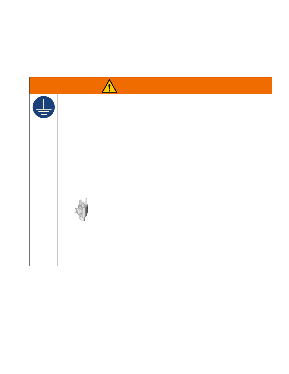
GROUNDING
This product must be grounded. In the event of an electrical short circuit, grounding reduces the risk of
electric shock by providing an escape wire for the electric current. This product is equipped with a cord
having a grounding wire with an appropriate grounding plug. The plug must be plugged into an outlet
that is properly installed and grounded in accordance with all local codes and ordinances.
• Improper installation of the grounding plug is able to result in a risk of electric shock.
• When repair or replacement of the cord or plug is required, do not connect the grounding wire to
either flat blade terminal.
• The wire with insulation having an outer surface that is green with or without yellow stripes is the
grounding wire.
• Check with a qualified electrician or serviceman when the grounding instructions are not completely
understood, or when in doubt as to whether the product is properly grounded.
• Do not modify the plug provided; if it does not fit the outlet, have the proper outlet installed by a
qualified electrician.
• This product is for use on a nominal 120V circuit and has a grounding plug similar to the plugs
illustrated in the figure below.
• Only connect the product to an outlet having the same configuration as the plug.
• Do not use an adapter with this product.
• Extension Cords:
• Use only a 3-wire extension cord that has a grounding plug and a grounding receptacle that accepts
the plug on the product.
• Make sure your extension cord is not damaged. If an extension cord is necessary, use 12 AWG (2.5
2
mm
) minimum to carry the current that the product draws.
• An undersized cord results in a drop in line voltage and loss of power and overheating.
3A6400A 3
Page 4

Warning
WARNING
Electric Motor Warnings
FIRE AND EXPLOSION HAZARD
Flammable fumes, such as solvent and paint fumes, in work area can ignite or explode. To help
prevent fire and explosion:
• Do not spray flammable or combustible materials near an open flame or sources of ignition such as
cigarettes, motors, and electrical equipment.
• Paint or solvent flowing through the equipment is able to result in static electricity. Static electricity
creates a risk of fire or explosion in the presence of paint or solvent fumes. All parts of the spray
system, including the pump, hose assembly, spray gun, and objects in and around the spray area
shall be properly grounded to protect against static discharge and sparks. Use Graco conductive or
grounded high-pressure airless paint sprayer hoses.
• Verify that all containers and collection systems are grounded to prevent static discharge. Do not
use pail liners unless they are anti-static or conductive.
• Connect to a grounded outlet and use grounded extensions cords. Do not use a 3-to-2 adapter.
• Do not use a paint or a solvent containing halogenated hydrocarbons.
• Do not spray flammable or combustible liquids in a confined area.
• Keep spray area well-ventilated. Keep a good supply of fresh air moving through the area.
• Sprayer generates sparks. Keep pump assembly in a well-ventilated area at least 20 feet (6.1 m)
from the spray area when spraying, flushing, cleaning, or servicing. Do not spray pump assembly.
• Do not smoke in the spray area or spray where sparks or flame is present.
• Do not operate light switches, engines, or similar spark producing products in the spray area.
• Keep area clean and free of paint or solvent containers, rags, and other flammable materials.
• Know the contents of the paints and solvents being sprayed. Read all Safety Data Sheets (SDSs)
and container labels provided with the paints and solvents. Follow the paint and solvent
manufacturer’s safety instructions.
• Keep a working fire extinguisher in the work area.
4 3A6400A
Page 5
Internal Combustion Engine Warnings
WARNING
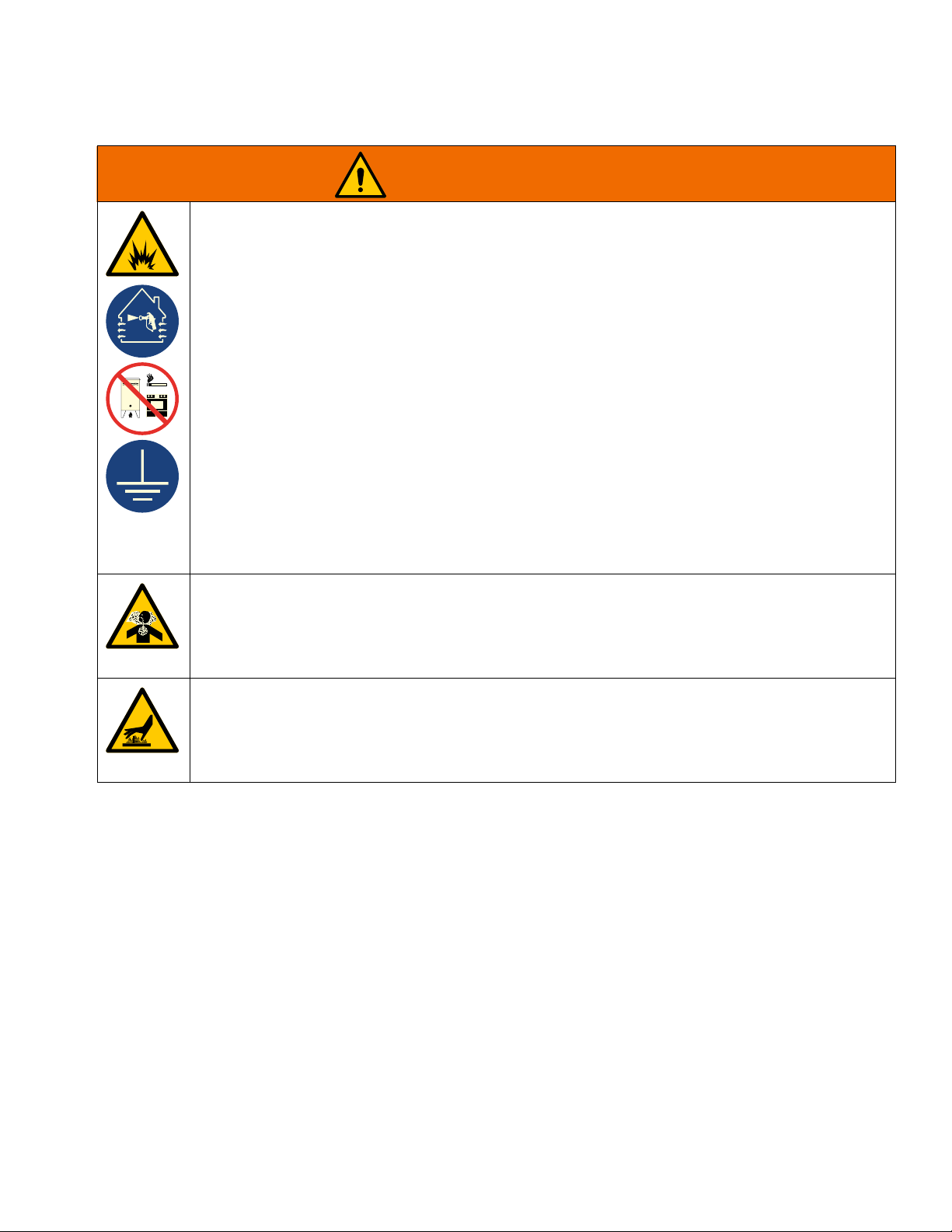
FIRE AND EXPLOSION HAZARD
Flammable fumes, such as solvent and paint fumes, in work area can ignite or explode. Paint or
solvent flowing through the equipment can cause static sparking. To help prevent fire and explosion:
• Use equipment only in well-ventilated area.
• Do not fill fuel tank while engine is running or hot; shut off engine and let it cool. Fuel is flammable
and can ignite or explode if spilled on hot surface.
• Eliminate all ignition sources; such as pilot lights, cigarettes, portable electric lamps, and plastic
drop cloths (potential static sparking).
• Ground all equipment in the work area. See Grounding instructions.
• Never spray or flush solvent at high pressure.
• Keep work area free of debris, including solvent, rags and gasoline.
• Do not plug or unplug power cords, or turn power or light switches on or off when flammable fumes
are present.
• Use only grounded hoses.
• Hold gun firmly to side of grounded pail when triggering into pail. Do not use pail liners unless they
are anti-static or conductive.
• Stop operation immediately if static sparking occurs or you feel a shock. Do not use equipment
until you identify and correct the problem.
• Keep a working fire extinguisher in the work area.
CARBON MONOXIDE HAZARD
Exhaust contains poisonous carbon monoxide, which is colorless and odorless. Breathing carbon
monoxide can cause death.
Warning
• Do not operate internal combustion engine in an enclosed area.
BURN HAZARD
Equipment surfaces and fluid that is heated can become very hot during operation. To avoid severe
burns:
• Do not touch hot fluid or equipment.
3A6400A 5
Page 6

Warning
WARNING
Electric Motor/Internal Combustion Engine Warnings
SKIN INJECTION HAZARD
High-pressure spray is able to inject toxins into the body and cause serious injury that can result in
amputation. In the event that injection occurs, get immediate surgical treatment.
• Do not aim the gun at, or spray any person or animal.
• Keep hands and other body parts away from the discharge. For example, do not try to stop leaks
with any part of the body.
• Always use the nozzle tip guard. Do not spray without nozzle tip guard in place.
• Use Graco nozzle tips.
• Use caution when cleaning and changing nozzle tips. In the case where the nozzle tip clogs while
spraying, follow the Pressure Relief Procedure for turning off the unit and relieving the pressure
before removing the nozzle tip to clean.
• Equipment maintains pressure after power is shut off. Do not leave the equipment energized or
under pressure while unattended. Follow the Pressure Relief Procedure when the equipment is
unattended or not in use, and before servicing, cleaning, or removing parts.
• Check hoses and parts for signs of damage. Replace any damaged hoses or parts.
• This system is capable of producing 3300 psi (228 bar, 22.8 MPa). Use Graco parts or accessories
that are rated a minimum of 3300 psi (228 bar, 22.8 MPa).
• Always engage the trigger lock when not spraying. Verify the trigger lock is functioning properly.
• Verify that all connections are secure before operating the unit.
• Know how to stop the unit and bleed pressure quickly. Be thoroughly familiar with the controls.
EQUIPMENT MISUSE HAZARD
Misuse can cause death or serious injury.
• Do not operate the unit when fatigued or under the influence of drugs or alcohol.
• Do not exceed the maximum working pressure or temperature rating of the lowest rated system
component. See Technical Specifications in all equipment manuals.
• Use fluids and solvents that are compatible with equipment wetted parts. See Technical
Specifications in all equipment manuals. Read fluid and solvent manufacturer’s warnings. For
complete information about your material, request Safety Data Sheets (SDSs) from distributor or
retailer.
• Do not leave the work area while equipment is energized or under pressure.
• Turn off all equipment and follow the Pressure Relief Procedure when equipment is not in use.
• Check equipment daily. Repair or replace worn or damaged parts immediately with genuine
manufacturer’s replacement parts only.
• Do not alter or modify equipment. Alterations or modifications may void agency approvals and
create safety hazards.
• Make sure all equipment is rated and approved for the environment in which you are using it.
• Use equipment only for its intended purpose. Call your distributor for information.
• Route hoses and cables away from traffic areas, sharp edges, moving parts, and hot surfaces.
• Do not kink or over bend hoses or use hoses to pull equipment.
• Keep children and animals away from work area.
• Comply with all applicable safety regulations.
6 3A6400A
Page 7

Warning
WARNING
PRESSURIZED ALUMINUM PARTS HAZARD
Use of fluids that are incompatible with aluminum in pressurized equipment can cause serious
chemical reaction and equipment rupture. Failure to follow this warning can result in death, serious
injury, or property damage.
• Do not use 1,1,1-trichloroethane, methylene chloride, other halogenated hydrocarbon solvents or
fluids containing such solvents.
• Do not use chlorine bleach.
• Many other fluids may contain chemicals that can react with aluminum. Contact your material
supplier for compatibility.
MOVING PARTS HAZARD
Moving parts can pinch, cut or amputate fingers and other body parts.
• Keep clear of moving parts.
• Do not operate equipment with protective guards or covers removed.
• Equipment can start without warning. Before checking, moving, or servicing equipment, follow the
Pressure Relief Procedure and disconnect all power sources.
TOXIC FLUID OR FUMES HAZARD
Toxic fluids or fumes can cause serious injury or death if splashed in the eyes or on skin, inhaled, or
swallowed.
• Read Safety Data Sheets (SDSs) to know the specific hazards of the fluids you are using.
• Store hazardous fluid in approved containers, and dispose of it according to applicable guidelines.
RECOIL HAZARD
Gun may recoil when triggered. If you are not standing securely, you could fall and be seriously
injured.
PERSONAL PROTECTIVE EQUIPMENT
Wear appropriate protective equipment when in the work area to help prevent serious injury, including
eye injury, hearing loss, inhalation of toxic fumes, and burns. Protective equipment includes but is not
limited to:
• Protective eyewear, and hearing protection.
• Respirators, protective clothing, and gloves as recommended by the fluid and solvent manufacturer.
CALIFORNIA PROPOSITION 65
The engine exhaust from this product contains a chemical known to the State of California to cause
cancer, birth defects or other reproductive harm.
This product contains a chemical known to the State of California to cause cancer, birth defects or
other reproductive harm. Wash hands after handling.
3A6400A 7
Page 8
Component Identification
Component Identification
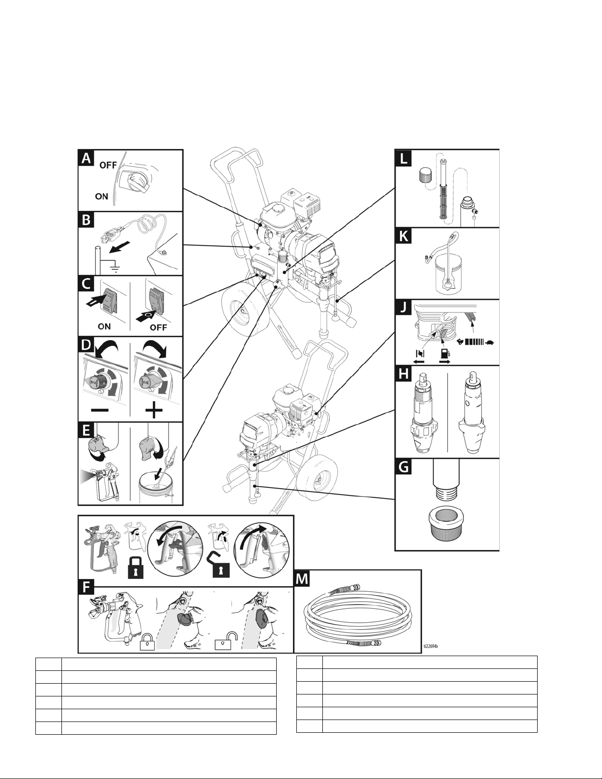
Standard Models (3400, 3900, 5900, 5900HD, 7900, 7900HD)
A Engine ON/OFF Switch
B Grounding Clamp
C Pump On/Off Switch
D Pressure Control
E Prime Valve
F Gun Trigger Lock
8 3A6400A
GStrainer
HPump
J Engine Controls
K Drain Hose
L Easy Out Pump Filter
MHose
Page 9

Component Identification
ProContractor Models (3900, 5900, 7900, 5900HD, 7900HD)
A Grounding Coil
B Smart Control 3.0 Display
C Pump ON/OFF Switch
D
WatchDog
E Pressure Control
F Prime Valve
G Gun Trigger Lock
HStrainer
3A6400A 9
TM
Switch
JDrain hose
KPump
L Rod Pull Feature
M Engine Controls
N
ProConnect
P Filter
R Engine ON/OFF Switch
S QuikReel
TM
II Pump Clamp
Page 10
Component Identification
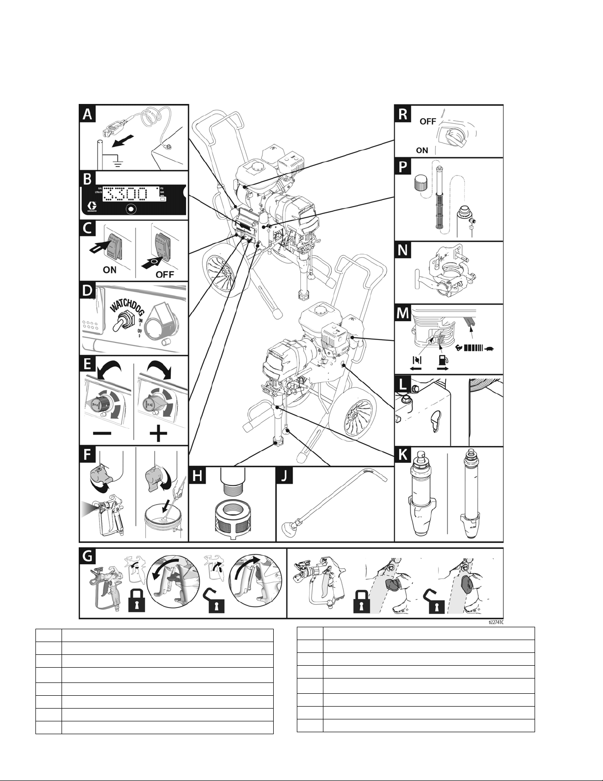
Ironman Models (5900, 7900, 7900HD)
A Grounding Coil
B Smart Control 3.0 Display
C Pump ON/OFF Switch
D
WatchDog
E Pressure Control
F Prime Valve
G Gun Trigger Lock
H Heavy Duty Strainer
10 3A6400A
TM
Switch
J Drain Hose
K MaxLife Pump
L Rod Pull Feature
M Engine Controls
N
ProConnect
P Easy Out Pump Filter
R Engine ON/OFF Switch
S Hose (not shown)
TM
II Pump Clamp
Page 11
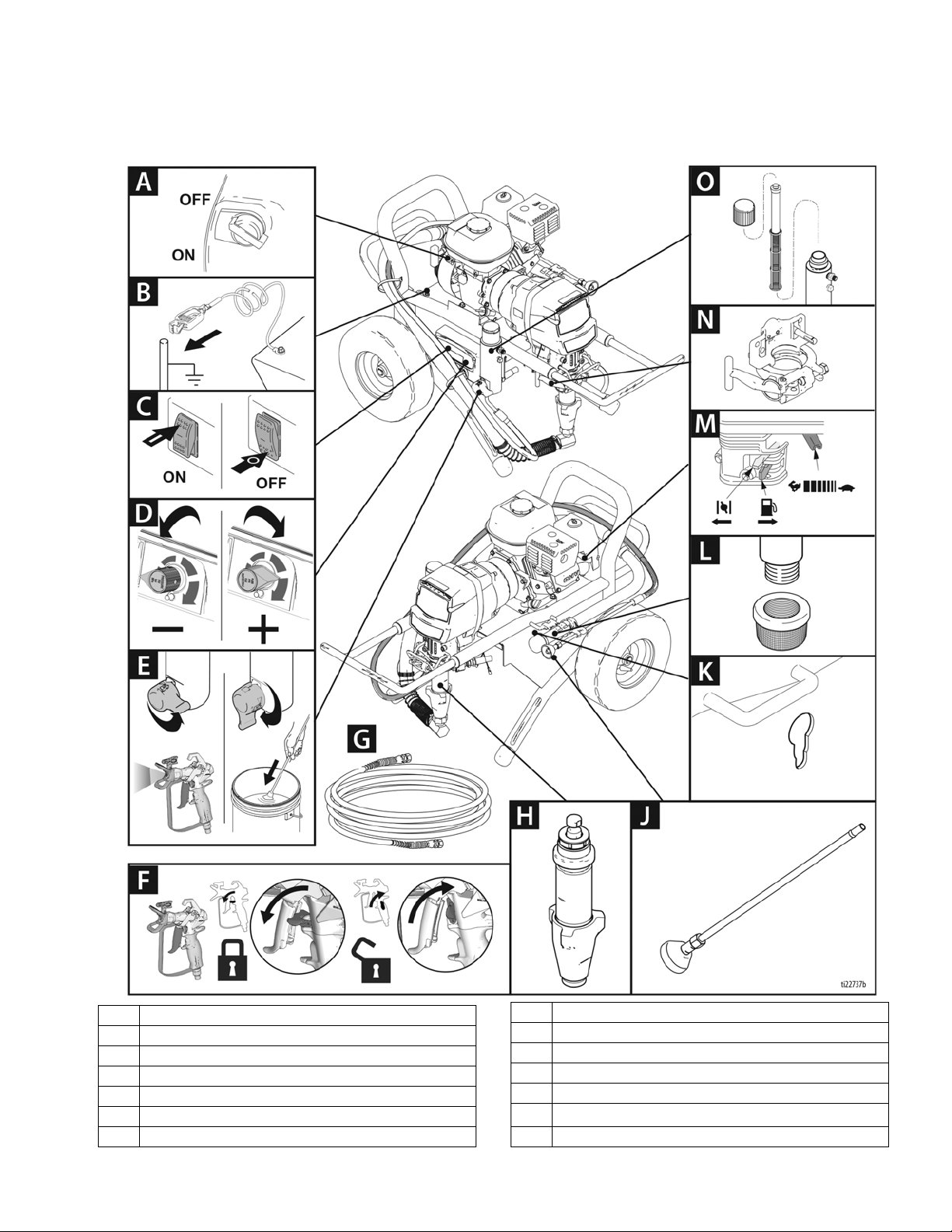
Lo-Boy Models (3900, 5900, 7900)
Component Identification
A Engine ON/OFF Switch
B Grounding Coil
C Pump ON/OFF Switch
D Pressure Control
E Prime Valve
F Gun Trigger Lock
GHose
3A6400A 11
H Pump
J Drain Hose
K Rod Pull Feature
LStrainer
M Engine Controls
N
ProConnect
O Easy Out Pump Filter
TM
II Pump Clamp
Page 12
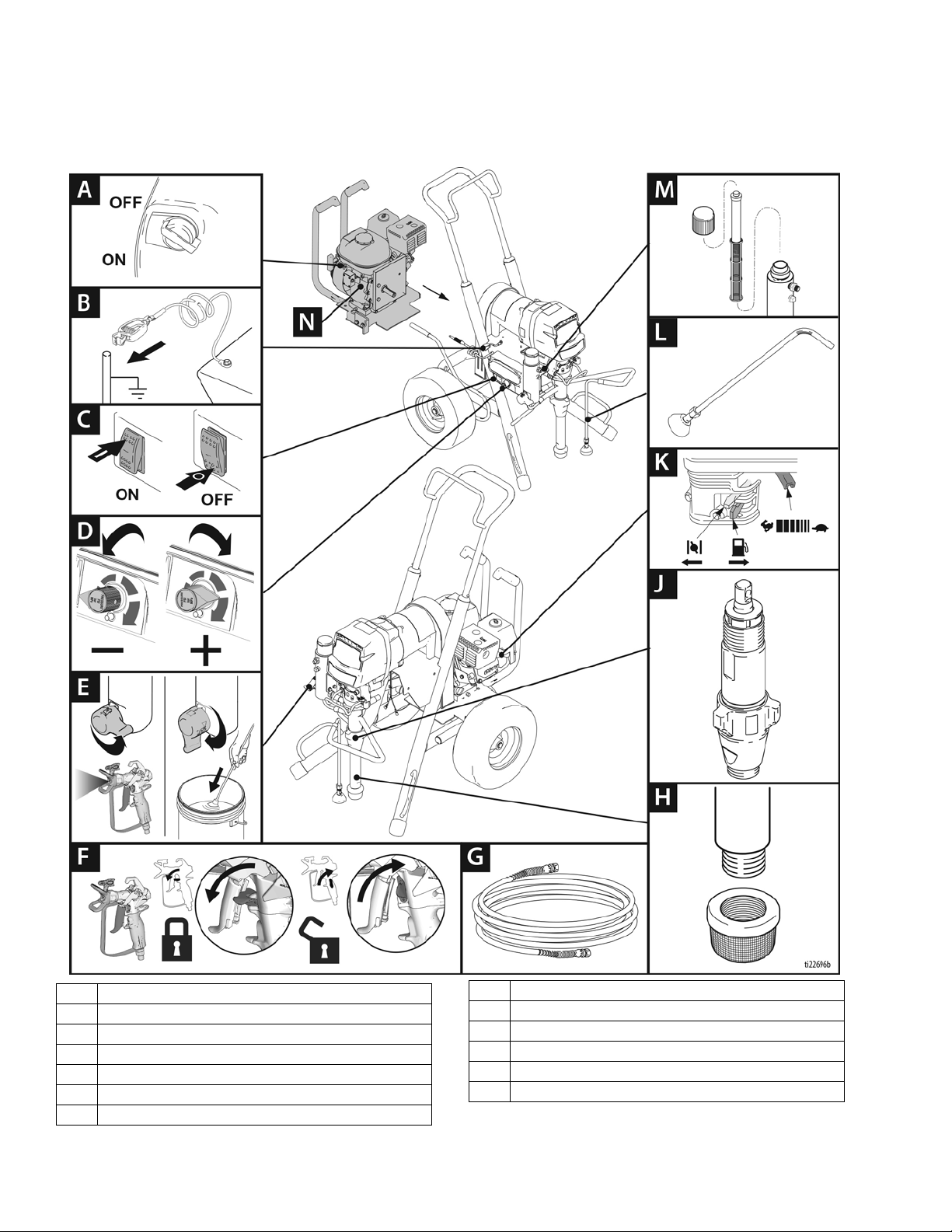
Component Identification
Convertible Models (5900)
A Engine ON/OFF Switch
B Grounding Coil
C Pump On/Off Switch
D Pressure Control
E Prime Valve
F Gun Trigger Lock
GHose
12 3A6400A
HStrainer
JPump
K Engine Controls
L Drain Hose
M Easy Out Pump Filter
NPower Pack
Page 13

Pressure Relief Procedure
ti5787a
Pressure Relief Procedure
Follow the Pressure Relief Procedure whenever
you see this symbol.
This equipment stays pressurized until pressure is
manually relieved. To help prevent serious injury from
pressurized fluid, such as skin injection, splashing
fluid and moving parts, follow the Pressure Relief
Procedure when you stop spraying and before
cleaning, checking, or servicing the equipment.
1. Engage trigger lock.
2. Turn gas engine ON/OFF siwtch to OFF. For
Convertible Models with electric motor, turn electric
motor ON/OFF switch to OFF, and unplug power
cord to electric motor.
3. Disengage trigger lock. Hold metal part of gun firmly
to side of grounded metal pail, and trigger gun to
relieve pressure.
4. Engage gun trigger lock.
5. Turn prime valve down to DRAIN position. Leave
prime valve down until ready to spray again.
6. If you suspect the spray tip or hose is clogged or
that pressure has not been fully relieved:
Grounding
Grounding Procedure for
Internal Combustion Engine
The equipment must be grounded to reduce the risk
of static sparking. Static sparking can cause fumes to
ignite or explode. Grounding provides an escape wire
for the electric current.
To ground sprayer: Attach sprayer grounding clamp to
earth ground.
Air and fluid hoses: Use only electrically conductive
hoses with a maximum of 500ft. (150 m) combined hose
length to ensure grounding continuity. Check electrical
resistance of hoses. If total resistance to ground
exceeds 29 megaohms, replace hose immediately.
Spray gun: Ground through connection to a properly
grounded fluid hose and pump.
a. VERY SLOWLY loosen the tip guard retaining
nut or the hose end coupling to relieve pressure
gradually.
b. Loosen the nut or the coupling completely.
c. Clear the obstruction in the hose or tip.
3A6400A 13
Page 14

Grounding
Grounding Procedure for
Electric Motor (Convertible
Models only)
The equipment must be grounded to reduce the risk
of static sparking and electric shock. An electric or
static spark can cause fumes to ignite or explode. An
improper ground can cause electric shock. A good
ground provides an escape wire for the electric
current.
This sprayer is equipped with a power cord that has a
ground wire and an appropriate grounding plug.
If using the electric motor, plug must be plugged into an
actual outlet that is properly installed and grounded in
accordance with all local codes and ordinances.
Do not modify the plug provided; if it does not fit the
outlet, have the proper outlet installed by a qualified
electrician.
Grounding of Pails
Solvent pails used when flushing: Follow local code.
Use only conductive metal pails, placed on a grounded
surface. Do not place the pail on a non-conductive
surface, such as paper or cardboard, which interrupts
grounding continuity.
ti25360a
Always ground a metal pail: connect a ground wire to
the pail. Clamp one end to the pail and the other end to
a true earth ground such as a water pipe.
To maintain ground continuity when sprayer is
flushed or pressure is relieved: hold metal part of
spray gun firmly to the side of a grounded metal pail
then trigger the gun.
Power Requirements
Convetible is only in USA or Canada.
• 100-120 VAC, 50/60 Hz, 15A, 1 phase.
Extension Cords
Use an extension cord with an undamaged ground
contact. If an extension cord is necessary, use a 3-wire,
12 AWG (2.5 mm²) minimum.
NOTE: Smaller gauge or longer extension cords may
reduce sprayer performance.
ti24585a
14 3A6400A
Page 15
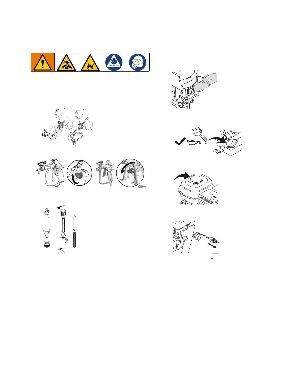
Setup
ti22698a
ti22701a
ti22743a
ti5952a
ti5953a
ti5787a
1.
All sprayers except ProContractor:
appropriate Graco high-pressure hose to sprayer.
2.
Select Units:
Install whip hose to fluid inlet of spray
gun and tighten securely.
3. Engage gun trigger lock.
Connect
Setup
5. Fill throat packing nut with TSL to prevent
premature packing wear. Do this each time you
spray.
6. Check engine oil level. Add SAE 10W-30 (summer)
or 5W-20 (winter), if necessary.
4. When spraying texture, remove inlet strainer and
filter bowl screen when spraying materials.
7. Fill fuel tank.
8. Attach sprayer grounding clamp to earth ground.
3A6400A 15
Page 16
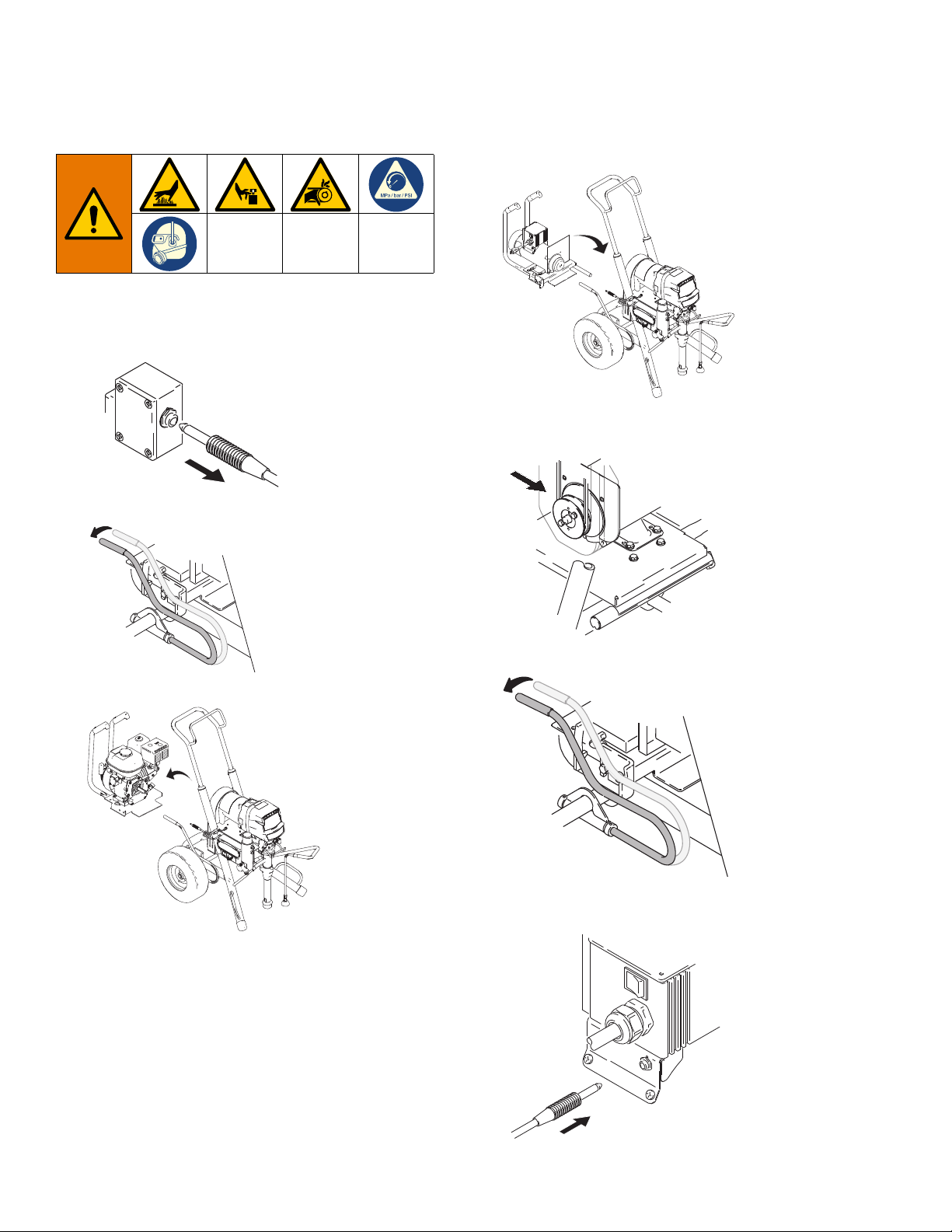
Setup
ti5774a
ti5775a
ti22702a
ti22703a
ti5772a
ti5775a
ti5779a
Convertible Models Only
Change Gas Engine to Electric Motor
1. Disconnect engine power cord.
2. Release tension bar.
4. Install motor; drop in and push forward.
5. Look through side vent holes and ensure drive belt
is in motor pulley.
3. Remove engine; tilt and slide back.
6. Secure motor with tension bar.
7. Plug in pressure control power cord.
16 3A6400A
Page 17
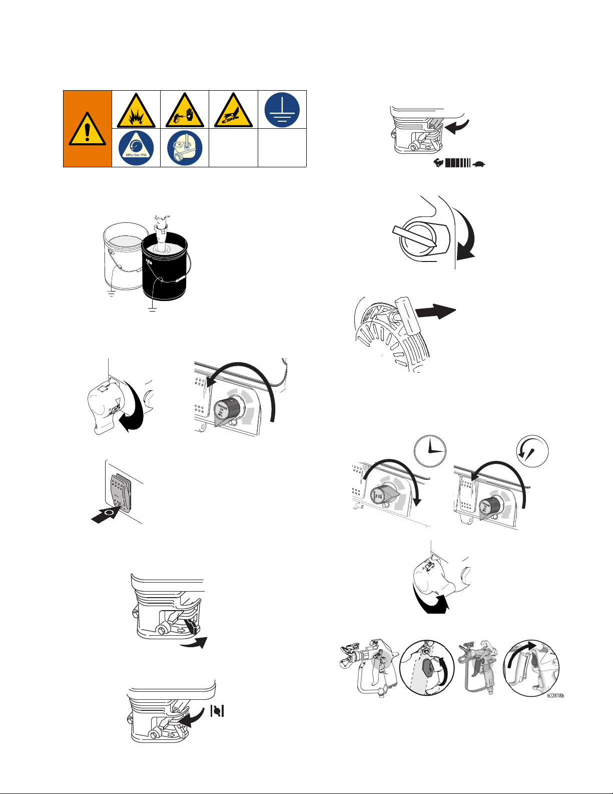
Startup
ti14844a
ti22708a
ti14842a
ti5790a
ti5248a
ti5249a
ti5250a
ti5262a
ti5263a
ti22709a
ti14845a
Startup
c. Set throttle to fast.
1. Place suction tube and drain tube in grounded metal
pail partially filled with flushing fluid. Attach ground
wire to pail and to earth ground.
2. Turn prime valve down to DRAIN position. Turn
pressure control counterclockwise to lowest
pressure.
3. Set pump switch OFF.
d. Set engine switch to ON.
5. Pull rope to start engine.
6. Increase pressure enough to start pump stroking
and allow fluid to circulate for 15 seconds; turn
pressure down and turn prime valve forward to
SPRAY position.
4. Start Engine
a. Move fuel valve to open.
7. Disengage spray gun trigger lock.
b. Move choke to closed.
3A6400A 17
Page 18
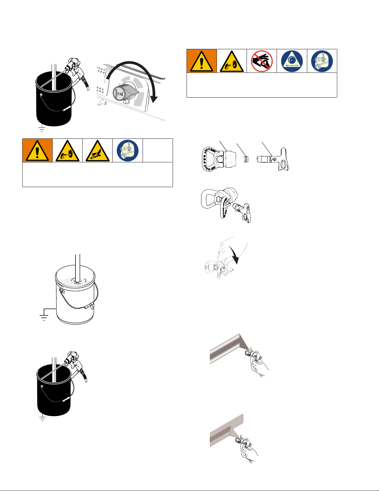
Startup
ti13243a
ti22710a
ti5797a
ti13243a
C
A
B
ti13023a
ti13024a
ti2710a
ti13030a
ti13025a
8. Hold gun against grounded metal flushing pail.
Trigger gun and increase fluid pressure slowly until
pump runs smoothly.
High-pressure spray is able to inject toxins into the
body and cause serious bodily injury. Do not stop
leaks with hand or rag.
9. Inspect fittings for leaks. If leaks occur, turn sprayer
OFF immediately. Perform Pressure Relief
Procedure steps 1-3, page 13. Tighten leaky
fittings. Repeat Startup procedure steps 1 - 5. If no
leaks, continue to trigger gun until system is
thoroughly flushed. Proceed to step 6.
Switch Tip™ Guard Assembly
To avoid serious injury from skin injection do not put
your hand in front of the spray tip when installing or
removing the spray tip and tip guard.
1. Perform Pressure Relief Procedure, page 13.
2. Engage gun trigger lock. Insert Switch Tip. Insert
seat and OneSeal
3. Insert Switch Tip.
4. Screw assembly onto gun. Tighten.
™
.
10. Place siphon tube in material pail.
11. Trigger gun again into flushing fluid pail until
material appears.
Spray
1. Spray test pattern. Increase pressure to eliminate
heavy edges. Use smaller tip size if pressure
adjustment can not eliminate heavy edges.
2. Hold gun perpendicular, 10-12 in. (25-30 cm) from
surface. Spray back and forth. Overlap by 50%.
Trigger gun after moving and release before
stopping.
18 3A6400A
Page 19
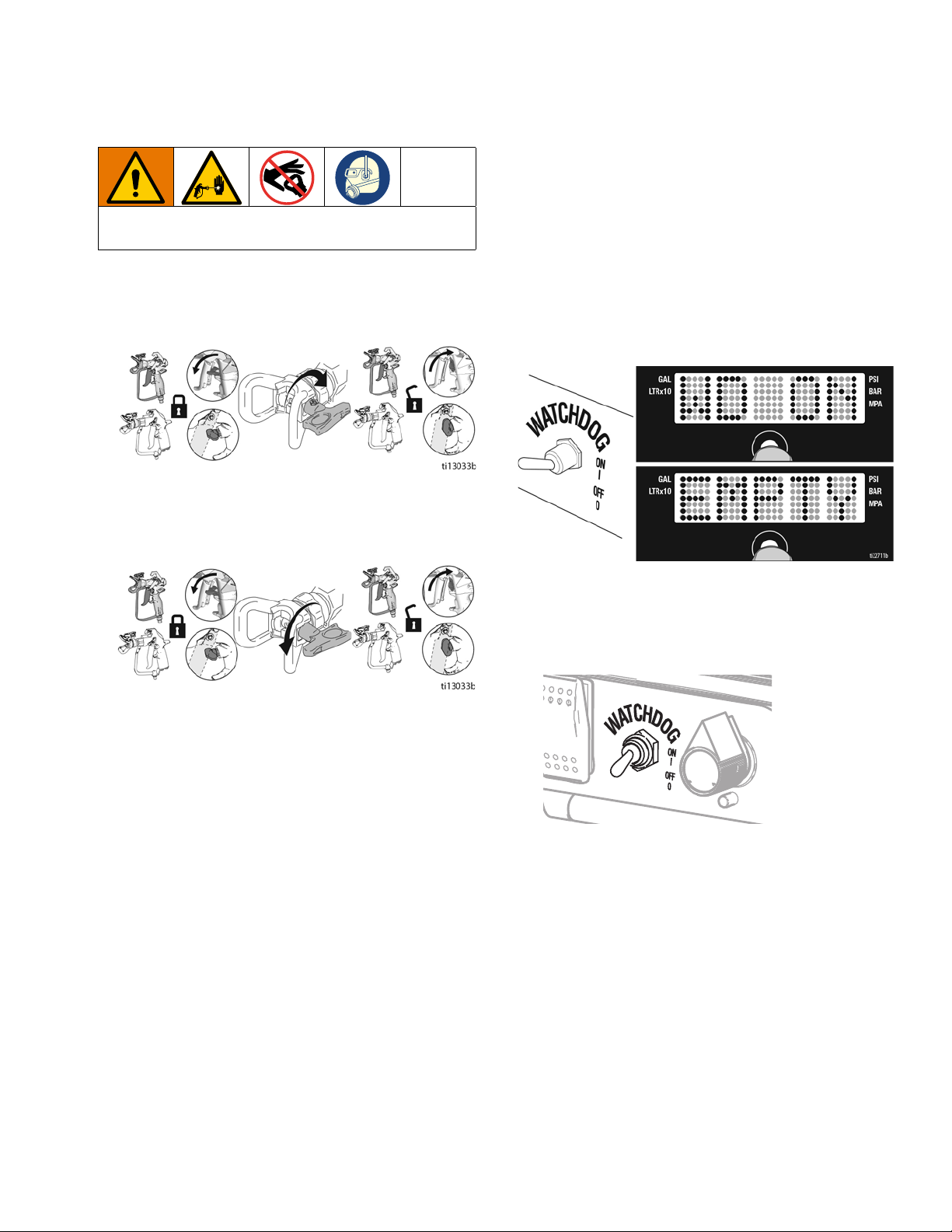
Startup
ti22712a
Clearing Tip Clogs
To avoid injury, never point gun at your hand or into a
rag!
1. Release trigger, engage trigger lock. Rotate Switch
Tip. Disengage trigger lock. Trigger gun to clear
clog.
2. Engage trigger lock. Return Switch Tip to original
position. Disengage trigger lock and continue
spraying.
WatchDog™ Protection System
(ProContractor and Ironman units only)
Pump stops automatically when material pail is empty.
To Activate:
1. Perform Startup.
2. Turn WatchDog switch ON and WD ON displays.
EMPTY displays/flashes and pump stops when
Watchdog protection system detects an empty
material pail.
3. Turn WatchDog switch OFF. Add material or
reprime sprayer. Turn pump switch OFF and ON to
reset WatchDog protection system. Turn WatchDog
switch back ON to continue to monitor material
level.
3A6400A 19
Page 20
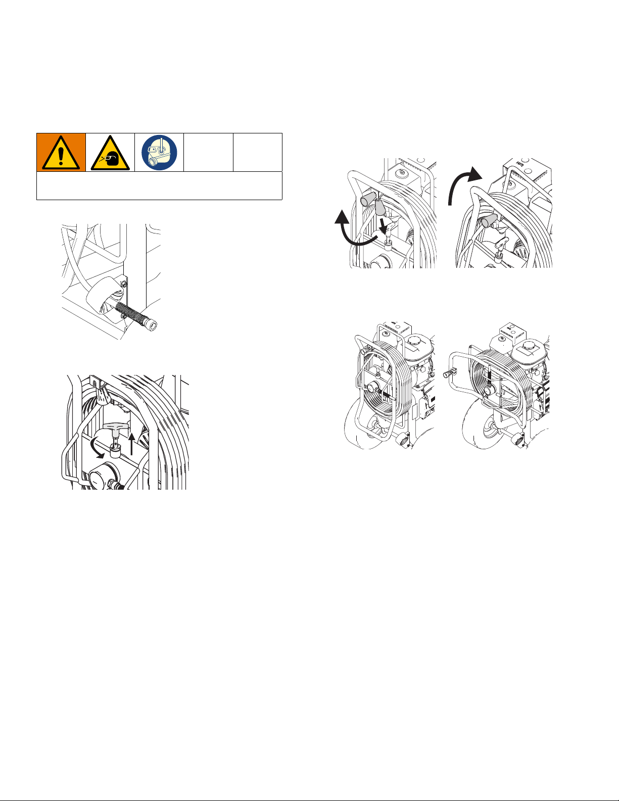
QuikReel™ (ProContractor units only)
ti13504a
ti22744a
ti22745a
(A)
(B)
ti22746a
QuikReel™
(ProContractor units only)
To avoid injury, keep your head clear of hose reel
while winding up hose.
1. Make sure hose is routed through hose guide.
3. Pull reel handle down and out. Turn clockwise to
reel in hose.
NOTE: The QuikReel can be locked into two
positions: Usage (A) and Storage (B).
2. Lift and turn pivot lock 90 to unlock hose reel. Pull
on hose to remove it from hose reel.
20 3A6400A
Page 21
LED Display
ti13243a
ti22714a
LED Display
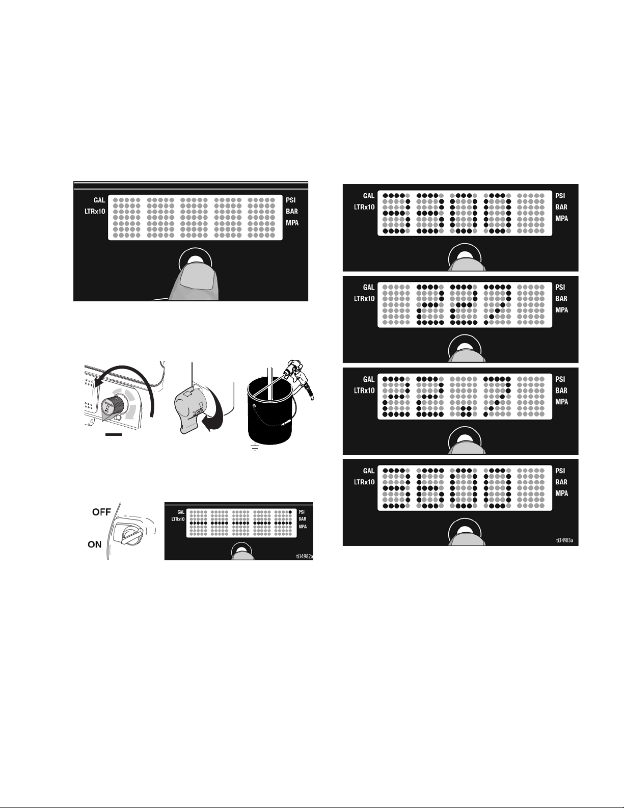
(ProContractor and Ironman units)
Operation Main Menu
Short press to move to next display. Press and hold (5
seconds) to change units or reset data.
1. Turn pressure to lowest setting. Trigger gun to
relieve pressure. Turn prime valve down to DRAIN
position.
Change Display Units
Press and hold DTS button for 5 seconds to change
pressure units (psi, bar, MPa) to desired units.
Selection of bar or MPa changes gallons to liters x 10.
To change display units DTS must be in pressure
display mode and pressure must be at zero.
2. Turn power ON. Pressure display appears. Dashes
will not appear unless pressure is less than 200 psi
(14 bar, 1,4 MPa).
3A6400A 21
Page 22
LED Display
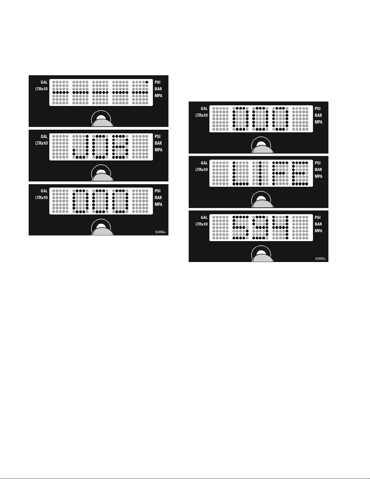
Job Gallons
1. Short press DTS button to move to Job Gallons (or
liters x 10).
Lifetime Gallons
1. Short press DTS button to move to Lifetime Gallons
(or liters x 10).
NOTE: LIFE scrolls briefly, then the number of
gallons sprayed above 1000 psi (70 bar, 7 MPa)
displays.
NOTE: JOB scrolls past, then the number of gallons
sprayed above 1000 psi (70 bar, 7 MPa) displays.
22 3A6400A
Page 23
Secondary Menu - Stored Data and
WatchDog Pump Protection Modes
LED Display
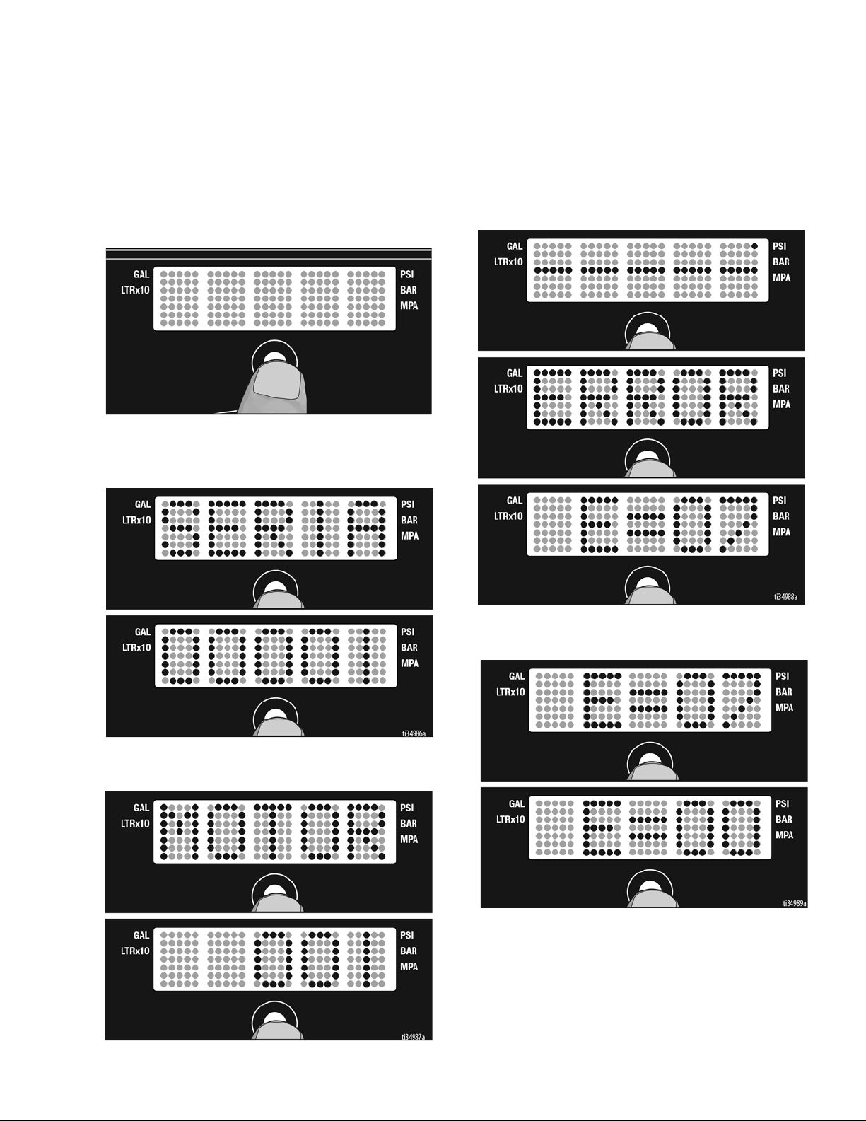
1. Perform Pressure Relief, steps 1 - 4 if they have
not already been done.
2. Turn power switch on while holding DTS button
down.
3. The sprayer model briefly displays (e.g. 5900),
SERIAL NUMBER scrolls past and then serial
number (e.g. 00001) displays.
5. Short press DTS button. LAST ERROR CODE
scrolls by and last error code is displayed; e.g.
E=07. See sprayer Repair manual for additional
information.
4. Short press DTS button and MOTOR ON scrolls
past and then total motor run hours are displayed.
6. Press and hold DTS button to clear error code to
zero.
3A6400A 23
Page 24
LED Display
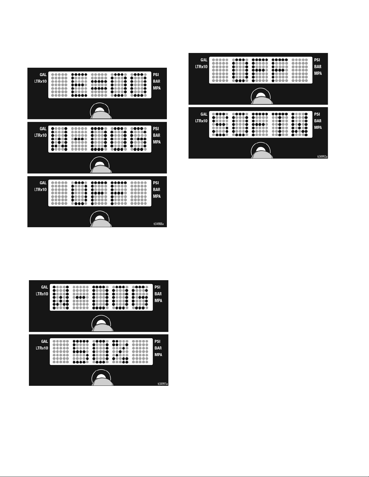
7. Short press DTS button. W-DOG scrolls past then
OFF displays if watchdog switch is OFF. ON
displays if Watchdog switch is ON.
9. Short press to move to SOFTWARE REV.
8. Press and hold (8 seconds) DTS button to move to
WatchDog Trigger % menu. Continue to hold DTS
button and Watchdog can be set to trigger at 30, 40,
50, or 60% of current sprayer pressure setting.
Release DTS button when desired % is displayed.
default is 50%.
24 3A6400A
Page 25
Cleanup
ti14844a
ti5248a
ti5249a
ti5250a
ti5262a
ti5263a
OFF
ti22729a
ti14846a
ti22730a
ti14847a
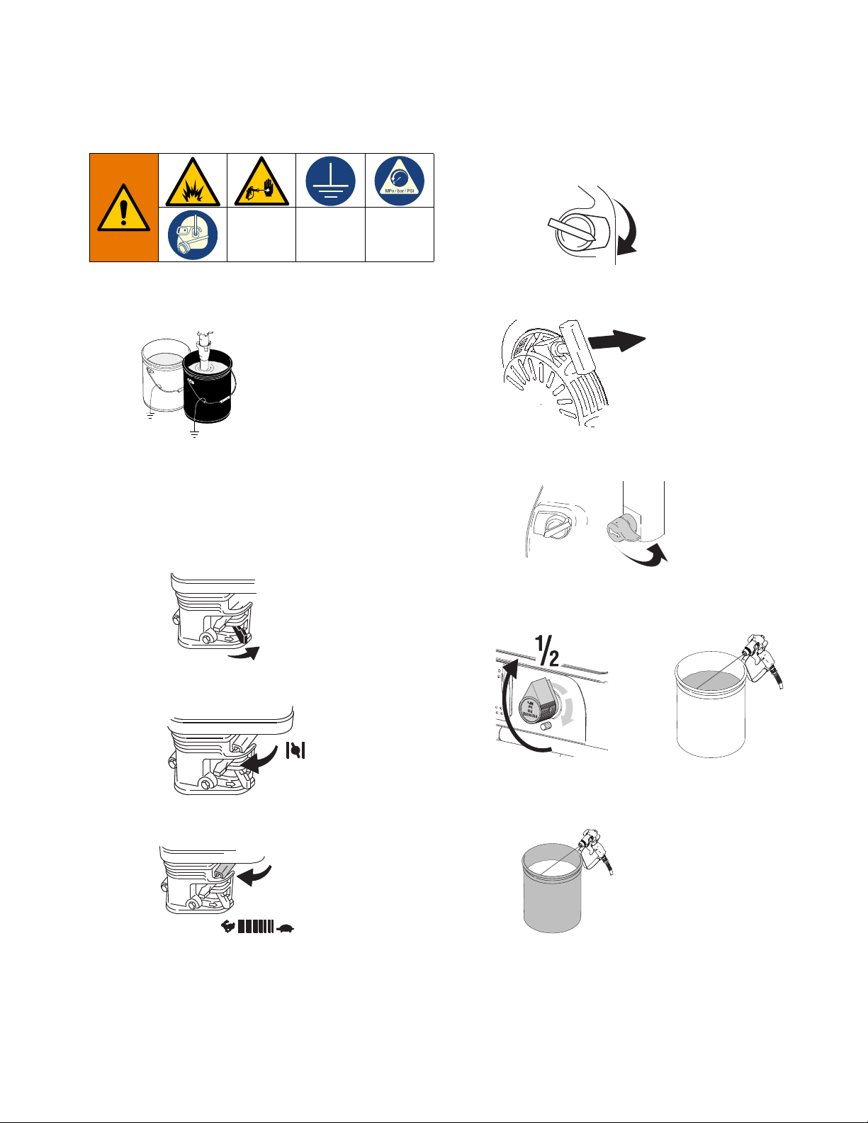
1. Perform Pressure Relief Procedure, page 13,
steps 1 - 4. Remove siphon tube set from paint and
place in flushing fluid. Remove tip guard from gun.
Cleanup
d. Set engine switch to ON.
3. Pull rope to start engine.
NOTE: Use water for water-base paint, mineral
spirits for oil-base paint, or other solvents
recommended by manufacturer.
2. Start Engine
a. Move fuel valve to open.
b. Move choke to closed.
c. Set throttle to fast.
4. Turn pump switch ON. Turn prime valve forward to
SPRAY position.
ON
5. Increase pressure to 1/2. Hold gun against paint
pail. Disengage trigger lock. Trigger gun until
flushing fluid appears.
6. Move gun to waste pail, hold gun against pail,
trigger gun to thoroughly flush system. Release
trigger and engage trigger lock.
7. Turn prime valve down to DRAIN position and allow
flushing fluid to circulate until flushing fluid appears
clear.
3A6400A 25
Page 26
Cleanup
ti14845a
ti14847a
ti22731a
ti14842a
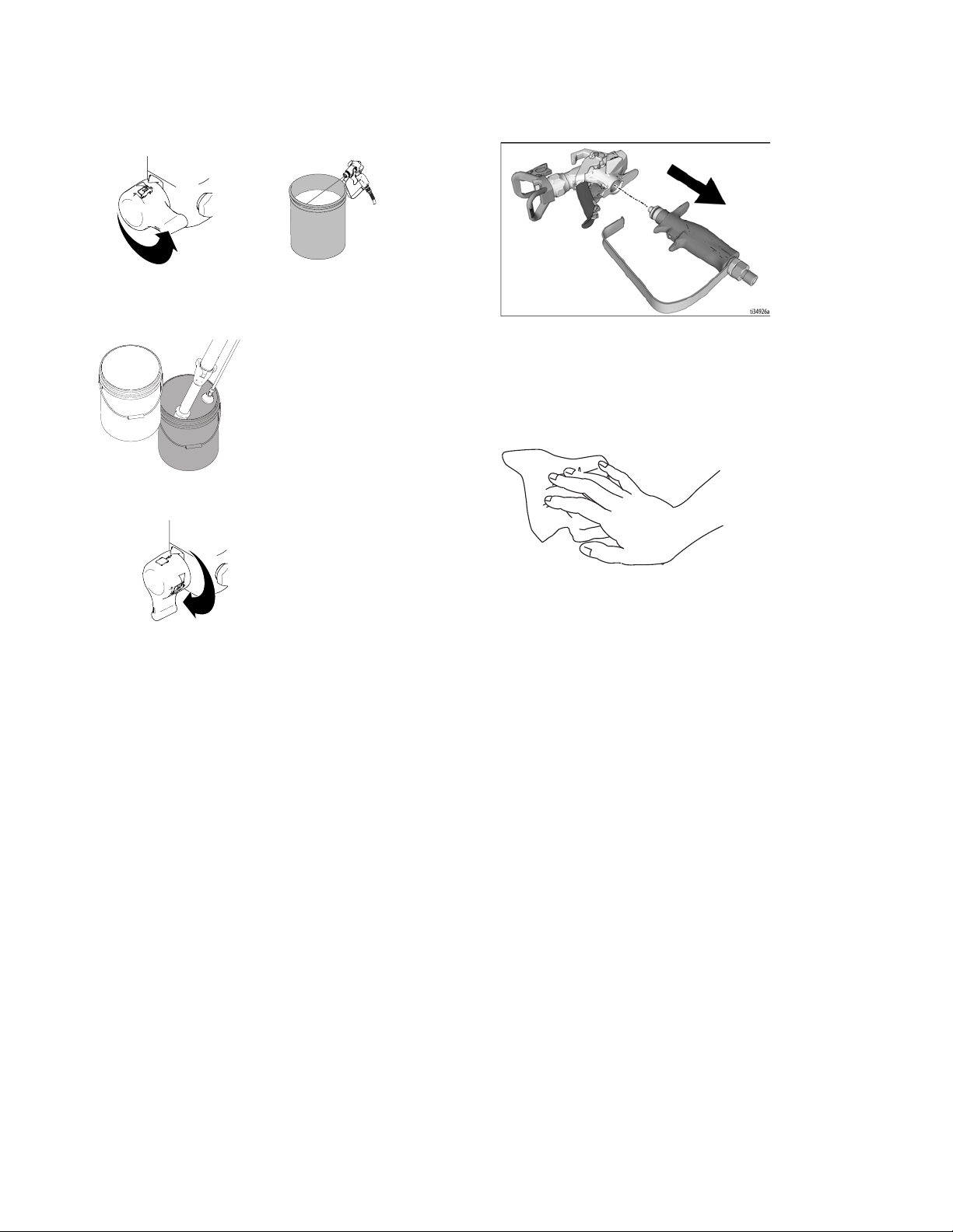
8. Turn prime valve forward to SPRAY position.
Trigger gun into flushing pail to purge fluid from
hose.
9. Raise siphon tube above flushing fluid and run
sprayer for 15 to 30 seconds to drain fluid. Turn
pump switch and engine OFF
10. Turn prime valve down DRAIN position.
11. Remove filters from gun and sprayer, if installed.
Clean and inspect. Install filters.
12. If flushing with water, flush again with mineral
spirits, or Pump Armor, to leave a protective coating
to prevent freezing or corrosion.
13. Wipe sprayer, hose and gun with a rag soaked in
water or mineral spirits.
ti2776a
26 3A6400A
Page 27
Maintenance
ti23054a
OIL FUNNEL
Perform Pressure Relief Procedure, page 13, before
performing maintenance.
NOTE: For detailed engine maintenance and
specifications, refer to separate Honda Engines Owner's
Manual, supplied.
DAILY: Check engine oil level and fill as necessary.
DAILY: Check hose for wear and damage.
DAILY: Check that all hose fittings are secure.
DAILY: Check gun safety for proper operation.
DAILY: Check pressure drain valve for proper
operation.
DAILY: Check and fill the gas tank.
Maintenance
DAILY: Check level of TSL in displacement pump
packing nut. Fill nut, if necessary. Keep TSL in nut to
help prevent fluid buildup on piston rod and premature
wear of packings and pump corrosion.
AFTER THE FIRST 20 HOURS OF OPERATION:
Drain engine oil and refill with clean oil. Reference
Honda Engines Owner's Manual for correct oil viscosity.
WEEKLY: Remove engine air filter cover and clean
element. Replace element, if necessary. If operating in
an unusually dusty environment: check filter daily and
replace, if necessary.
Replacement elements can be purchased from your
local HONDA dealer.
AFTER EACH 100 HOURS OF OPERATION:
Change engine oil. Reference Honda Engines Owner's
Manual for correct oil viscosity.
SPARK PLUG: Use only BPR6ES (NGK) or
W20EPR-U (NIPPONDENSO) plug. Gap plug to 0.028
to 0.031 in. (0.7 to 0.8 mm). Use spark plug wrench
when installing and removing plug.
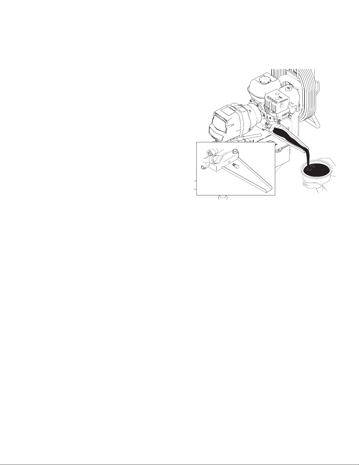
Use the supplied engine oil funnel when draining oil.
3A6400A 27
Page 28
Troubleshooting
Troubleshooting
Problem Cause Solution
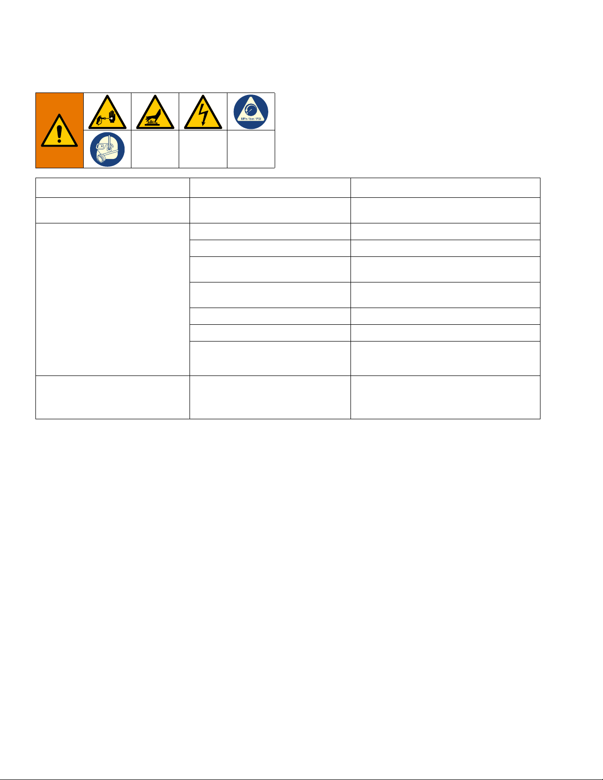
E=XX is displayed Fault condition exists. Determine fault correction from table, page
Engine will not start Engine switch is OFF. Turn engine switch ON.
Engine is out of gasoline. Refill gas tank. Honda Engine Manual.
Engine oil level is low. Try to start engine. Replenish oil, if necessary.
Spark plug disconnected or damaged. Connect spark plug cable or replace spark
Engine is cold. Use choke.
Fuel shutoff lever is OFF. Move lever to ON position.
Oil is seeping into combustion
chamber.
False tripping of WatchDog system.
EMPTY is displayed. Pump does not
run.
Operating conditions out of WatchDog
parameters.
Pump output is low, page 29.
35.
Honda Engine Manual.
plug.
Remove spark plug. Pull starter 3 to 4 times.
Clean or replace spark plug. Start engine.
Keep sprayer upright to avoid oil seepage.
Turn pressure down. Contact Graco Technical
Assistance to adjust WatchDog parameters.
Operate without WatchDog active (see
Operation manual).
28 3A6400A
Page 29
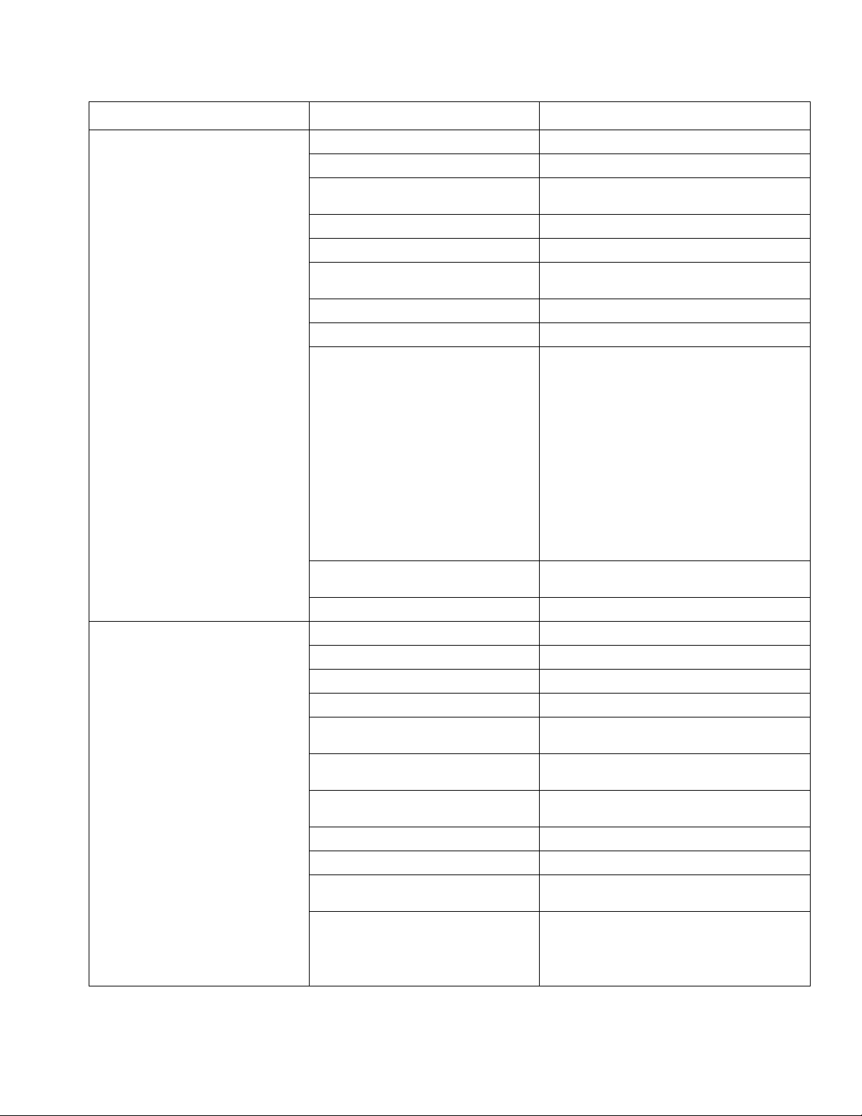
Problem Cause Solution
Troubleshooting
Engine operates, but displacement
pump does not operate
Error code displayed. See LED Display Messages, page 38.
Pump switch is OFF. Turn pump switch ON.
Pressure setting too low. Turn pressure adjusting knob clockwise to
Fluid filter is dirty. Clean filter.
Tip or tip filter is clogged. Clean tip or tip filter (see gun manual).
Displacement pump piston rod is stuck
due to dried paint.
Connecting rod is worn or damaged. See Parts manual.
Drive housing is worn or damaged. See Parts manual.
Electrical power is not energizing
clutch field.
increase pressure.
Repair pump (see pump manual).
See Parts manual.
See LED Display Messages, page 38.
With pump switch ON and pressure turned to
MAXIMUM, use a test light to check for power
between clutch test points on control board.
Remove clutch wires from control board and
measure resistance across clutch coil. At 70°
F, the resistance must be between for 3900 -
1.2 + 0.2 Ω, for 5900/7900 1.7 ± 0.2 Ω; if not,
replace pinion housing.
Have pressure control checked by authorized
Graco dealer.
Clutch is worn, damaged, or incorrectly
positioned.
Pinion assembly is worn or damaged. Repair or replace pinion assembly. Page 39.
Pump output is low Strainer is clogged. Clean strainer.
Piston ball is not seating. Service piston ball (see pump manual).
Piston packings are worn or damaged. Replace packings (see pump manual).
O-ring in pump is worn or damaged. Replace o-ring (see pump manual).
Intake valve ball is not seating
properly.
Intake valve ball is packed with
material.
Engine speed is too low. Increase throttle setting (see operation
Clutch is worn or damaged. Adjust or replace clutch. Page 39.
Pressure setting is too low. Increase pressure (see operation manual).
Fluid filter, tip filter or tip is clogged or
dirty.
Large pressure drop in hose with
heavy materials.
Adjust or replace clutch. See page 39.
Clean intake valve (see pump manual).
Clean intake valve (see pump manual).
manual).
Clean filter (see gun manual).
Use larger diameter hose and/or reduce
overall length of hose. Use of more than 100 ft
of 1/4 in. hose significantly reduces
performance of sprayer. Use 3/8 in. hose for
optimum performance (50 ft minimum).
3A6400A 29
Page 30
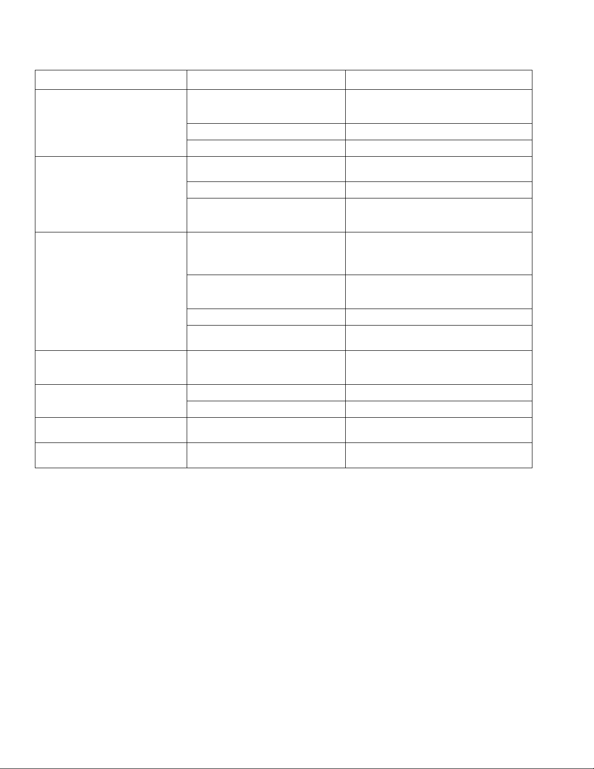
Troubleshooting
Problem Cause Solution
Excessive paint leakage into throat
packing nut
Fluid is spitting from gun Air in pump or hose. Check and tighten all fluid connections.
Pump is difficult to prime Air in pump or hose. Check and tighten intake tube connections.
Clutch squeaks each time clutch
engages
High engine speed at no load Misadjusted throttle setting. Reset throttle to 3300 engine rpm at no load.
Throat packing nut is loose. Remove throat packing nut spacer. Tighten
Throat packings are worn or damaged. Replace packings (see pump manual).
Displacement rod is worn or damaged. Replace rod (see pump manual).
Tip is partially clogged. Clear tip (see gun manual).
Fluid supply is low or empty. Refill fluid supply. Prime pump (see operation
Intake valve is leaking. Clean intake valve. Be sure ball seat is not
Pump packings are worn. Replace pump packings (see pump manual).
Engine speed is too high. Decrease throttle setting before priming pump
Clutch surfaces are not matched to
each other when new and may cause
noise.
throat packing nut just enough to stop
leakage.
Reprime pump (see operation manual).
manual). Check fluid supply often to prevent
running pump dry.
Reduce engine speed and cycle pump as
slowly as possible during priming.
nicked or worn and that ball seats well.
Reassemble valve.
(see operation manual).
Clutch surfaces need to wear into each other.
Noise will dissipate after a day of run time.
Worn engine governor. Replace or service engine governor.
Gallon counter not working Bad sensor, broken or disconnected
wire. Displaced or missing magnet.
No display, sprayer operates Display damaged or has bad
connection.
Check connections. Replace sensor or wire.
Reposition or replace magnet.
Check connections. Replace display.
30 3A6400A
Page 31
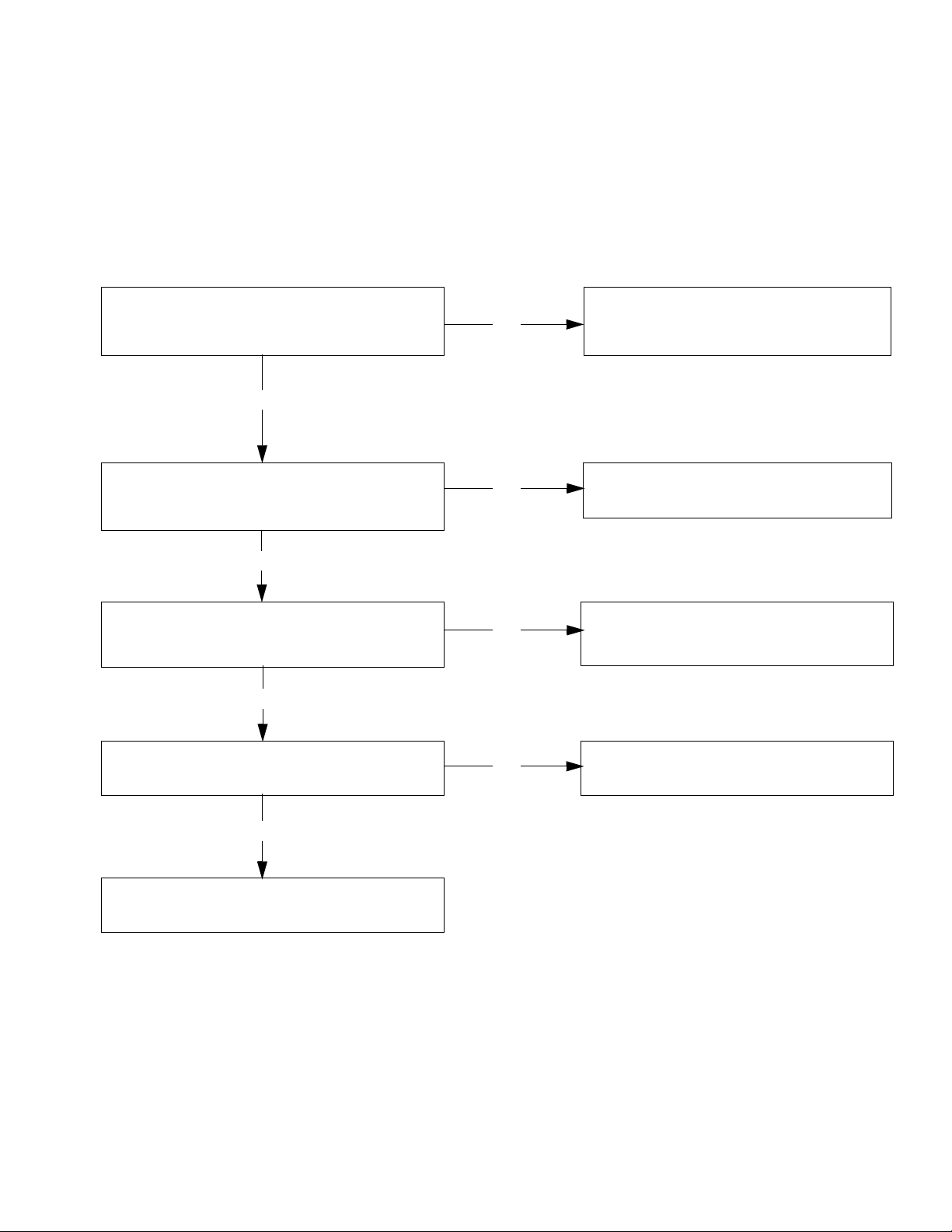
Fluid Pump Runs Constantly
With a pressure gauge plumbed into the paint hose, start the engine. Turn pump switch ON. Does sprayer exceed maximum pressure?
Pump problem. See the proper fluid pump
manual for the sprayer for further
troubleshooting procedures.
Disconnect clutch wires from control board (see
diagram, page 36). Does the pump stop
running?
Mechanical problem in the clutch pinion
assembly (clutch may be close to the
Make sure clutch wires are plugged in (see
diagram, page 36). Do the clutch test points
read 10-18 DC volts?
Check for a short from the two clutch wires
to the frame. If shorted, repair or replace
faulty wire.
Unplug transducer from control board.
Bad transducer.
Replace and test with a new one.
Replace the control board.
YES
NO
YES
YES
YES
NO
NO
NO
1. Perform Pressure Relief Procedure, page 13, turn
prime valve forward to SPRAY position, and turn
power switch OFF.
2. Remove control box cover.
Troubleshooting Procedure:
Troubleshooting
3A6400A 31
Page 32
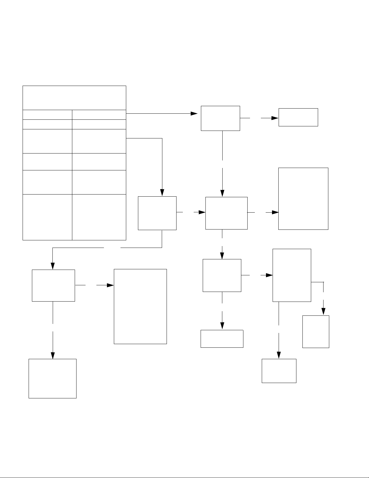
Troubleshooting
Go to step 5.
Does the
clutch
engage?
Go to step 2.
Do you have
proper engine
voltage?
Go to step 4.
Is 1-3 Ohms
reading
present?
Mechanical
problem. Repair
or replace
clutch/pinion
assembly.
Replace the
potentiometer.
Go to step 3.
Is 10-12
VDC
present?
Check wiring
from J1 and J2
for proper
connection. If
proper
connection is
detected, repair
or replace engine
If low resistance is
present in step 4,
the problem is a
shorted field.
Replace pinion.
If an open in the
wiring is present,
check pinion
wiring
connections.
Connect
a test
transducer to
the board.
Does the
clutch
engage?
Go to step 1.
Does switch
test positive?
Replace the
switch.
Remove control box cover. Turn
sprayer ON. Observe control board
Green and Red LED lights.
No light
Once Normal operation
Red light on
continuously
Control board
commanding
pump to run
Green light on
continuously
WatchDog
enabled
Flashing See error code
section for further
troubleshooting
Red light on
continuously with
potentiometer
OFF after a
replacement
board is installed
Model not
selected
YES
NO
NO
NO
YES
Replace
the
control
board.
NO
NO
YES
Replace
the
transducer.
YES
YES
NO
YES
Control Board Malfunction
Troubleshooting Procedure
(see following page for actual steps):
32 3A6400A
Page 33
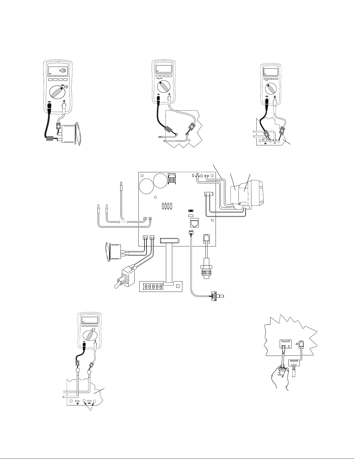
Control Board Malfunction (Steps)
-
J1
J2
12 -20 AC
V
-
+
-
10-12 DC
V
-
-
+
+
J10
J5
J9
J4J3
J1J2
LED
D12
J5
-
1-3 ohms
-
+
STEP 1.
Turn engine
OFF and set
meter to
continuity.
To Ground
STEP 3.
Leave engine
running and turn
switch ON. Turn
potentiometer to
high and set
meter to DC
volts.
STEP 2.
Turn engine
ON. Set meter
to AC volts and
connect wires
to control
board.
On/Off Switch
To Clutch
Field
To Engine
Control
Board
WatchDog
Premium Display Board
Potentiometer
Transducer
Clutch Test Points
Pinion
Assembly
Drive
Housing
Pump
On/Off
Switch
Engine
Generator
Control
Board
Clutch Test Points
Clutch
Field
Control
Board
Control
Board
Control
Board
Clutch
Field
STEP 5.
Turn engine
ON and turn
switch ON.
STEP 4.
Turn engine
OFF and
unplug
clutch wires.
Set meter to
Ohms.
ti14938a
ti14939a
ti14940a
ti14943a
ti14942a
ti14941a
BEEP
Troubleshooting
+
-
3A6400A 33
Page 34
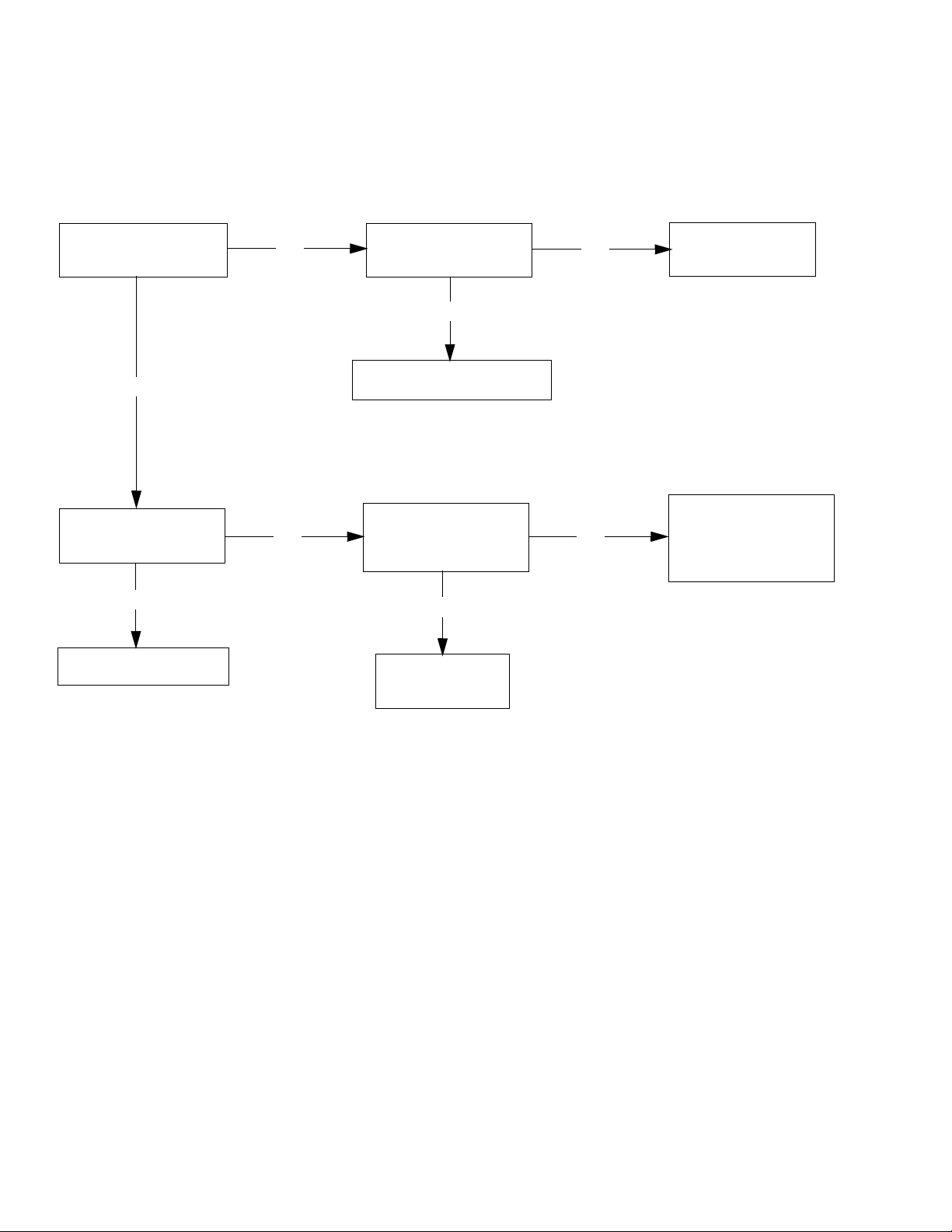
Troubleshooting
See Step 1. Is there over 100 AC volts?
See step 2. Is there
over 100 AC volts?
Replace the power switch.
See Step 3. Is there
over 100 DC volts?
See engine test section.
Replace engine
control board.
YES
NO
YES
YES
YES
NO
NO
NO
Repair or replace
the power cord.
See Step 4. Is there
continuity through the
thermal sensor?
If engine is hot, let
cool and retest. If
step 4 still shows an
open, replace engine.
Convertible Electric Motor Will Not Run
Troubleshooting Procedure
(see following page for actual steps):
34 3A6400A
Page 35
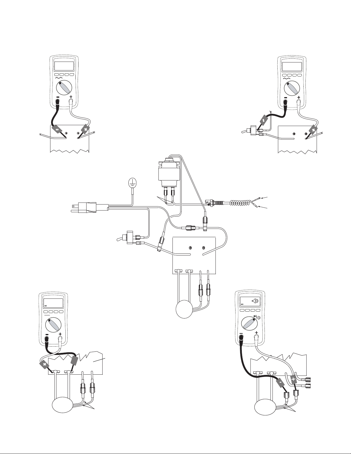
Convertible Electric Motor Will Not Run (Steps)
V
-
-
L2
L1
+
V
-
-
L2
L1
+
TS TS
+M -M
L2
L1
TS
TS
+M
-M
BEEP
-
TS TS
+M -M
100 + DC
V
-
STEP 1.
Plug in cord and turn
switch ON. Connect
wires to control board
and turn meter to AC
volts.
STEP 2.
Plug in cord and turn
switch ON. Connect
wires to control board
and turn meter to AC
volts.
STEP 3.
Plug in cord and turn
switch ON. Turn
meter to DC volts.
STEP 4.
Check the engine
thermal sensor (meter
should read continuity).
Note: engine should
be cooled down. Turn
meter to continuity test.
Black
White
Electric Engine Control Board
Electric Engine Control Board
Engine
Control
Board
Black
White
Black to
power cord
Electric
Engine
Electric
Engine
Yellow Yellow
Transformer
Jack
Ground
Black
Black
Black
Black
Black
White
White
Engine Control Board
Power Cord
Black to Tips
White to Barrel
AC power to
control board
ti14922a
ti14923a
ti14924a
ti14921a
ti14920a
Engine
Control
Board
Electric
Engine
Troubleshooting
-
+
-
3A6400A 35
Page 36
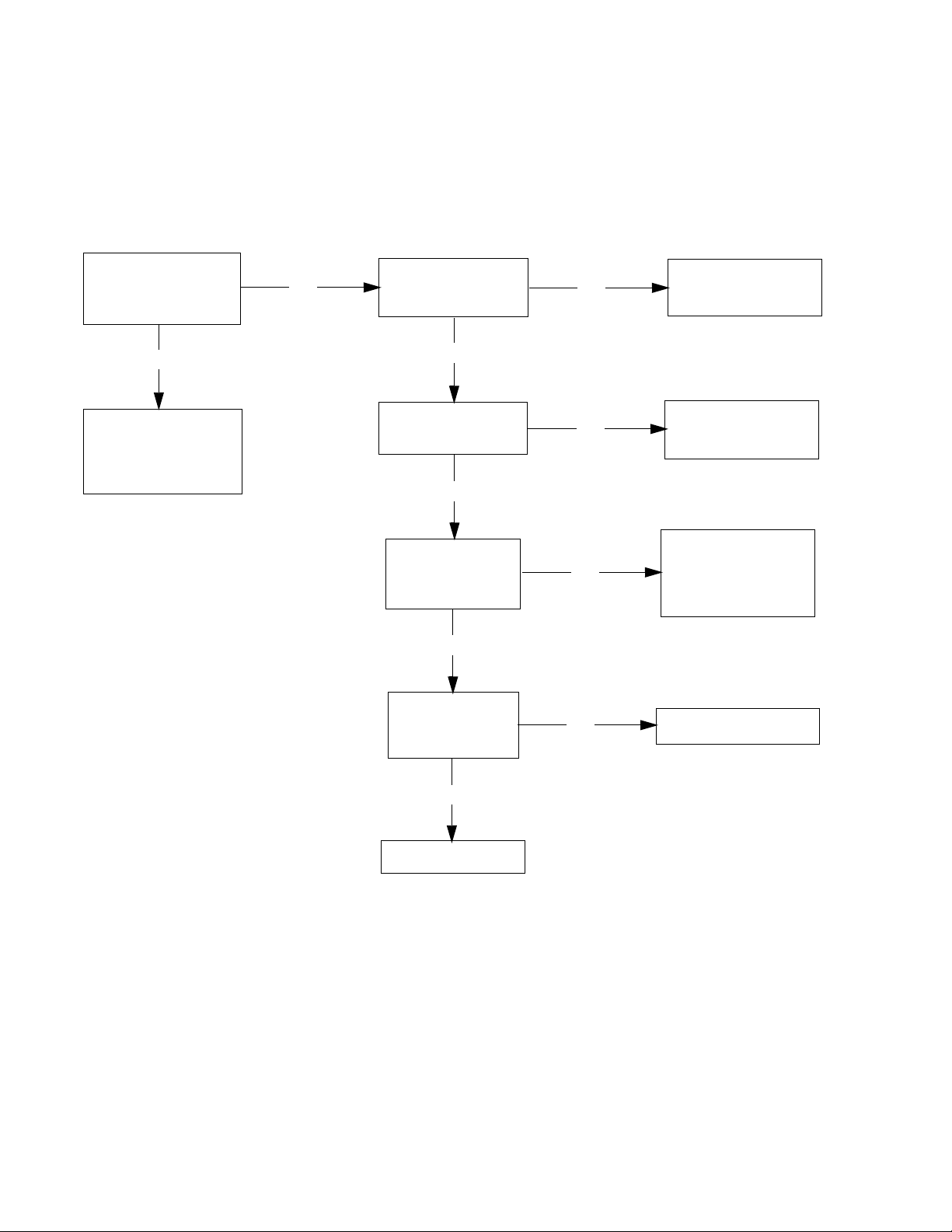
Troubleshooting
See step 1.
Is there over 10-20
AC volts?
YES
NO
YES
YES
YES
NO
NO
NO
YES
See step 2.
Is there continuity?
Repair or replace
the power cord.
See the sprayer
control board
troubleshooting in
this manual.
See step 3.
Is there continuity?
Repair or replace
the power cord.
See step 4.
Is there over 100
AC volts?
Repair or replace
wire splice(s) on
the power cord
wires.
See step 5.
Is there over
10-20 AC volts.
Replace transformer.
Replace cord jack.
NO
Convertible Electric Motor Runs No AC Output to Sprayer Control Board
Troubleshooting Procedure
(see following page for actual steps):
36 3A6400A
Page 37
Troubleshooting
10-20 AC
V
-
-
+
-
BEEP
-
TS TS
+M -M
L2
L1
10-20 AC
V
-
-
+
L2
L1
V
-
-
+
-
BEEP
-
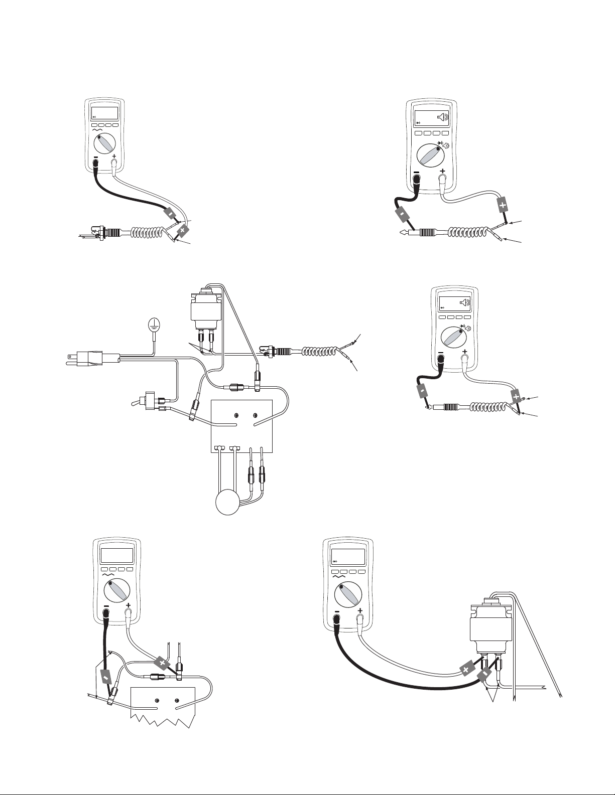
STEP 1.
Plug in cord and turn
switch ON. Connect
wires to transformer
and power cord. Turn
meter to AC volts.
White to barrel
Power Cord
Engine Control Board
STEP 2.
Check AC power cord
for an open wire. Turn
meter to continuity
test. Meter should
read continuity.
STEP 4.
Plug in cord and turn
switch ON. Partially
connect wires to
splice. Turn meter to
AC volts.
STEP 3.
Check AC power
cord for an open
wire. Turn meter to
continuity test.
Meter should read
continuity.
STEP 5.
Plug in cord and
turn switch ON.
Partially connect
wires to splice.
Turn meter to AC
volts.
Black to tips
AC power to
control board
Jack
Transformer
White to barrel
Power Cord
Black to tips
AC power to
control board
White to barrel
Black to tips
White to barrel
Black to tips
Power Cord
AC power to
control board
Power Cord
AC power to
control board
Jack
Transformer
Black
Black
Black
Black
Black
White
White
Electric
Engine
Ground
Transformer
Transformer
Black
Black
Black
Jack
Electric Engine Control Board
Black
White
White
Power
Cord
ti14927a
ti14929a
ti14928a
ti14930a
ti14926a
ti14925a
Convertible Electric Motor Runs - No AC Output to Sprayer Control Board (Steps)
3A6400A 37
Page 38
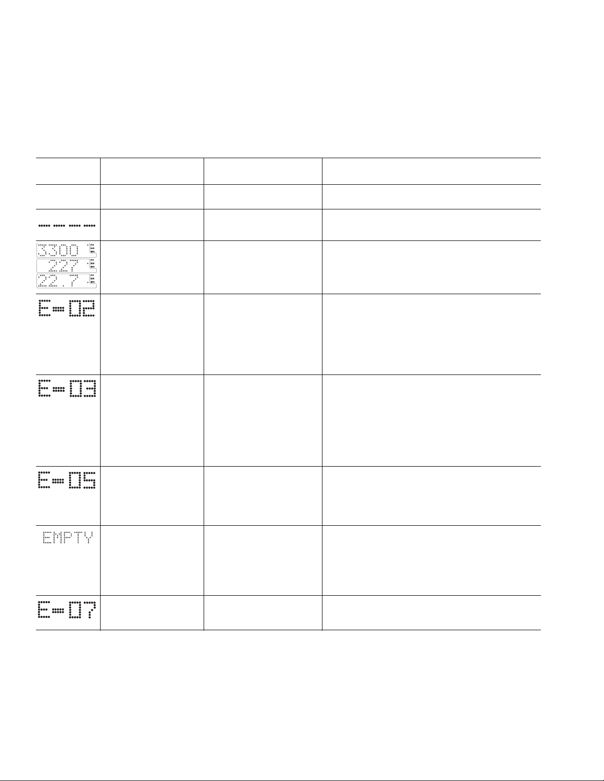
LED Display Messages
LED Display Messages
• Display messages are not available on all sprayers
• Blinking LED total count equals digital error code
i.e., two blinks is the same as E=02
DISPLAY* SPRAYER OPERA-
TION
No Display Sprayer may be
pressurized.
Sprayer may be
pressurized.
Sprayer is pressurized.
Power is applied.
(Pressure varies with
tip size and pressure
control setting).
Sprayer stops. Engine
is running.
Sprayer stops. Engine
is running.
Sprayer stops. Engine
is running.
Sprayer stops. Engine
is running.
(with constant
green LED)
Sprayer stops. Engine
is running.
INDICATION ACTION
Loss of power or display
not connected.
Pressure less than
200 psi (14 bar, 1.4 MPa).
Normal operation. Spray
Exceeded pressure limit. 1. Check fluid path for clogs, such as clogged filter.
Pressure transducer faulty,
bad connection or broken
wire.
High clutch current. 1. Check wiring connections.
Loss of paint to pump or
severe pressure loss.
Pressure greater than
2000 psi (138 bar, 14 MPa)
while in Flush Timer Mode.
Check power source. Relieve pressure before repair
or disassembly. Verify display is connected.
Increase pressure as needed.
2. Open prime valve and gun if running AutoClean.
3. Use Graco paint hose, 1/4 in. x 50 ft minimum.
Smaller hose or metal braid hose may result in
pressure spikes.
4. Replace transducer if fluid path is not clogged
and proper hose is used.
1. Check transducer connection.
2. Disconnect and reconnect transducer plug to
ensure good connection with control board
socket.
3. Open prime valve. Replace sprayer transducer
with known good transducer and run sprayer.
Replace transducer if sprayer runs or control
board if sprayer does not run.
Measure: 1.2 + 0.2 Ω (GMAX II 3900);
2.
1.7 + 0.2 Ω (GMAX II 5900/ 7900 & TexSpray
7900HD) across clutch field at 70°F.
3. Replace clutch field assembly.
1. Check for empty paint condition, clogged inlet
strainer, failed pump or severe leak.
2. Reduce pressure and turn pump switch OFF
and ON to restart pump.
3. WatchDog function can be deactivated by
turning WatchDog switch OFF.
1. Open prime valve and gun.
2. Verify no flow obstructions or clogged filter.
* Error codes also appear on control board as a blinking red
LED. LED is an alternate to digital messages.
1. Remove two screws (71) and swing down cover (130).
2. Start engine. Blink count is the same as error code(E=0X).
38 3A6400A
After a fault, follow these steps to restart sprayer:
1. Correct fault condition
2. Turn sprayer OFF
3. Turn sprayer ON
Page 39
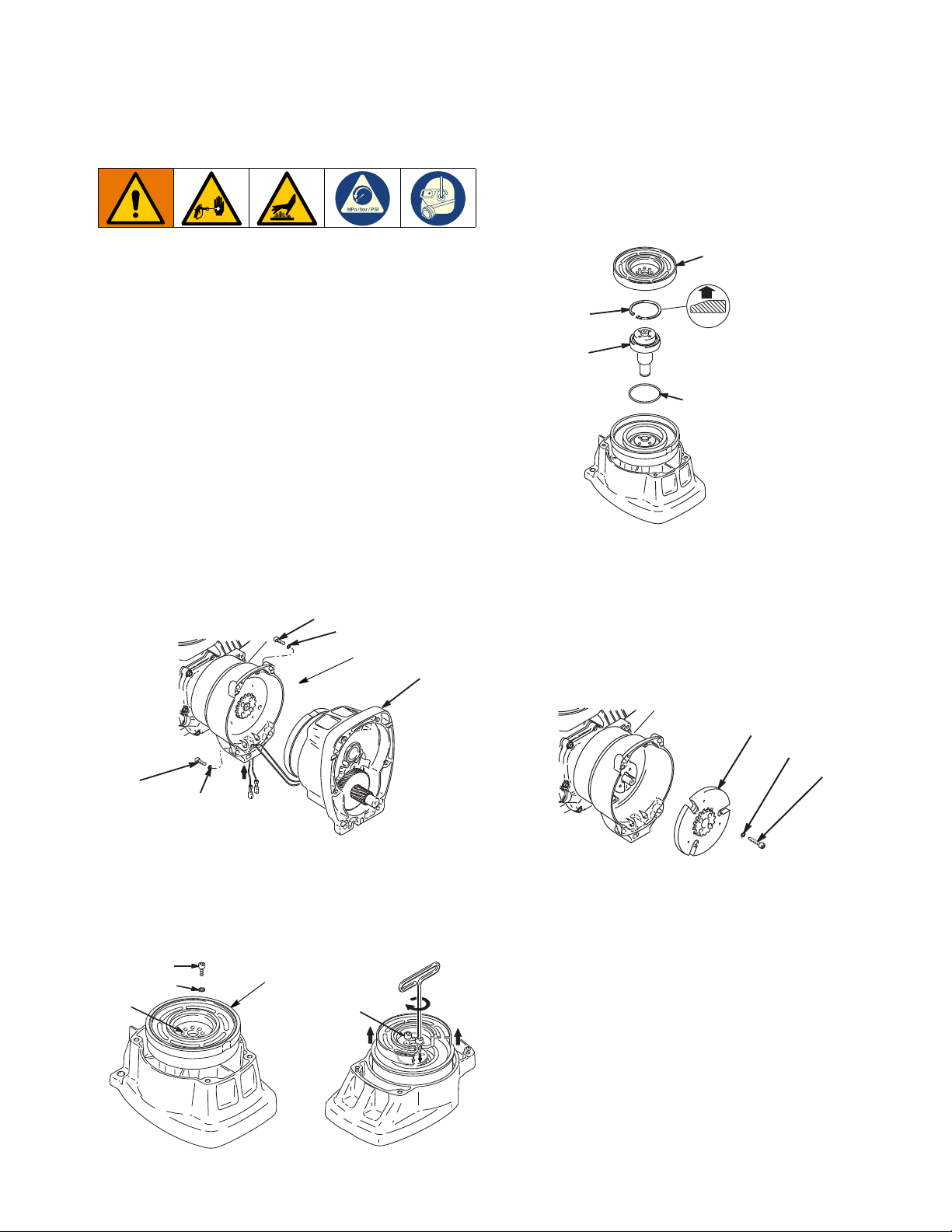
Pinion Assembly/Clutch Armature/Clamp
36
37
36
37
29
ti5480a
19
E
28
24
ti5481a
ti5987b
E
29
29b
29a
ti5482a
27
29d
TIA
Pinion Assembly/Clutch Armature/Clamp
6. Remove retaining ring (29b).
7. Turn pinion assembly over and tap pinion shaft
(29a) out with plastic mallet.
Perform Pressure Relief Procedure, page 13, before
performing these tasks.
Pinion Assembly/Clutch Armature Removal
Pinion Assembly
If pinion assembly (29) is not removed from clutch
housing (19), do 1. through 3. Otherwise, start at 4.
1. Remove drive housing.
2. Disconnect clutch cable connectors from inside of
pressure control.
a. Remove two screws (71) and swing down cover
(130a).
b. Disconnect engine leads from board to engine.
c. Remove strain reliefs 130r and 123.
3. Remove four screws (36) and pinion assembly (29).
4. Place pinion assembly (29) on bench with rotor side
up.
5. Remove four screws (28) and lock washers (24).
Install two screws in threaded holes (E) in rotor.
Alternately tighten screws until rotor comes off.
Clutch Armature
8. Use an impact wrench or wedge something
between clutch armature (25) and clutch housing to
hold engine shaft during removal.
9. Remove four screws (23) and lock washers (24).
10. Remove armature.
3A6400A 39
Page 40
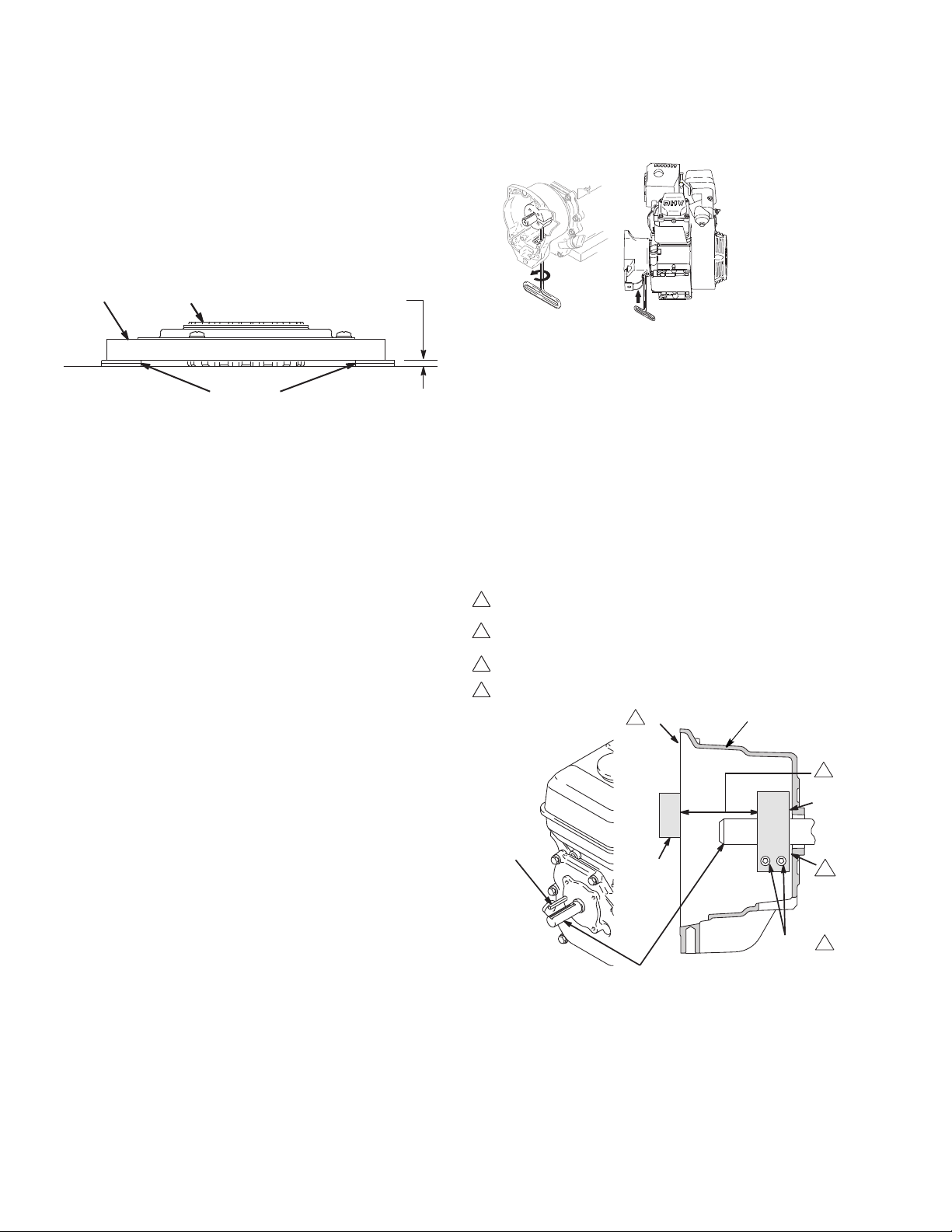
Pinion Assembly/Clutch Armature/Clamp
0.12+01 in (3.0+.25 mm)
25
26
dimes
ti6321a
ti6199a
"
!
TIA
19
4
3
2
1
Face of clutch housing
1.550 ± .010 in. (39.37 ± .25 mm) - GMAX 3400 and 3900
2.612 ± .010 in. (66.34 ± .25 mm) - GMAX 5900 and 7900
Torque to 125 ±.10 in-lb (14 ±1.1 N•m)
Chamfer this side
Installation
Clutch Armature
1. Lay two stacks of two dimes on smooth bench
surface.
2. Lay armature (25) on two stacks of dimes.
3. Press center of hub (26) down to bench surface.
4. Install armature (25) on engine drive shaft.
5. Install four screws (23) and lock washers (24) with
torque of 125 in-lb.
Pinion Assembly
1. Check o-ring (29d) and replace if missing or
damaged.
2. Tap pinion shaft (29a) in with plastic mallet.
Clamp Installation
1. Install engine shaft key (18).
2. Tap clamp (22) onto engine shaft (A). Maintain
dimension shown note 2. Chamfer must face
engine.
3. Check dimension: Place rigid, straight steel bar (B)
across face of clutch housing (19). Use accurate
measuring device to measure distance between bar
and face of clamp. Adjust clamp as necessary.
Torque two screws (24) to 125 ±10 in-lb (14 ±1.1
N•m).
3. Install retaining ring (29b) with beveled side facing
up.
4. Place pinion assembly on bench with rotor side up.
5. Apply thread sealant to screws. Install four screws
(28) and lock washers (24). Alternately torque
screws to 125 in-lb until rotor is secure. Use
threaded holes to hold rotor.
6. Install pinion assembly (29) with four screws (36)
and washers (37).
7. Connect clutch cable connectors to inside of
pressure control.
Clamp Removal
1. Remove engine.
2. Drain gasoline from tank according to Honda
manual.
3. Tip engine on side so gas tank is down and air
cleaner is up.
4. Loosen two screws (24) on clamp (22),
5. Push screwdriver into slot in clamp (22) and remove
clamp.
40 3A6400A
Page 41
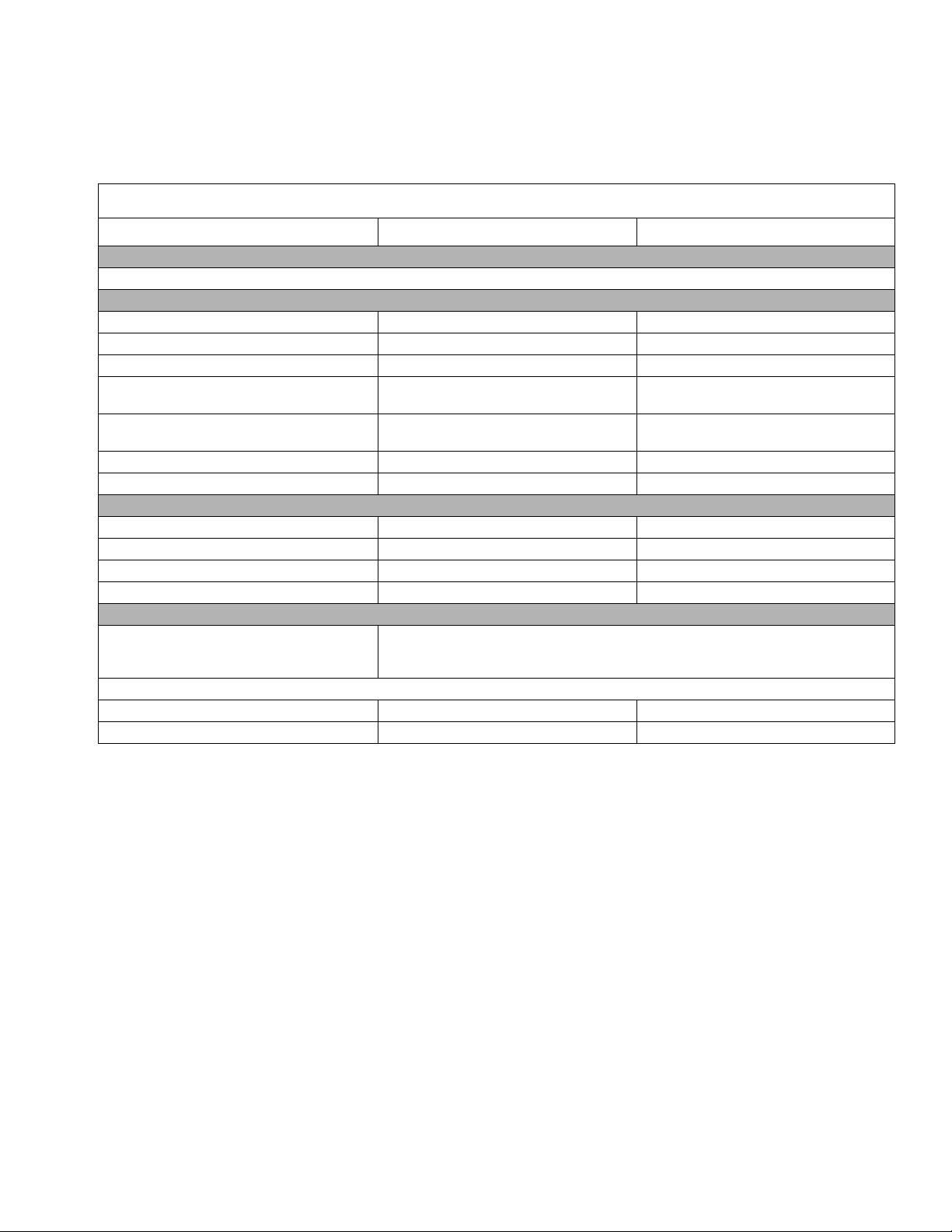
Technical Data
3400 Models
U.S. Metric
Engine
Honda GX120 Engine
Sprayer
Maximum Working Pressure 3300 psi 228 bar, 22.8 MPa
Maximum Tip Size: 0.027 in. tip 0.027 in. tip
Maximum Delivery Rating 0.75 gpm 2.84 lpm
Inlet Paint Strainer
Outlet Paint Filter
Pump Inlet Size 1 1/4-12 UNF-2A 1 1/4-12 UNF-2A
Fluid Outlet Size 1/4 npsm from fluid filter 1/4 npsm from fluid filter
Dimensions
Weight: 89 lb 40.5 kg
Height (handle extended): 40.8 in. 103.6 cm
Length (handle extended): 35.0 in. 88.9 cm
Width: 22.3 in. 56.6 cm
12 mesh (1523 micron)
stainless steel screen, reusable
60 mesh (250 micron)
stainless steel screen, reusable
12 mesh (1523 micron)
stainless steel screen, reusable
60 mesh (250 micron)
stainless steel screen, reusable
Technical Data
Wetted parts
Noise Level:
Sound Power 100 dBa per ISO 3744 100 dBa per ISO 3744
Sound Pressure 86 dBa measured at 3.1 ft 86 dBa measured at 1 m
zinc- and nickel-plated carbon steel, PTFE, nylon, polyurethane, UHMW,
fluoroelastomer, acetal, leather, aluminum, tungsten carbide,
stainless steel, chrome plating
3A6400A 41
Page 42
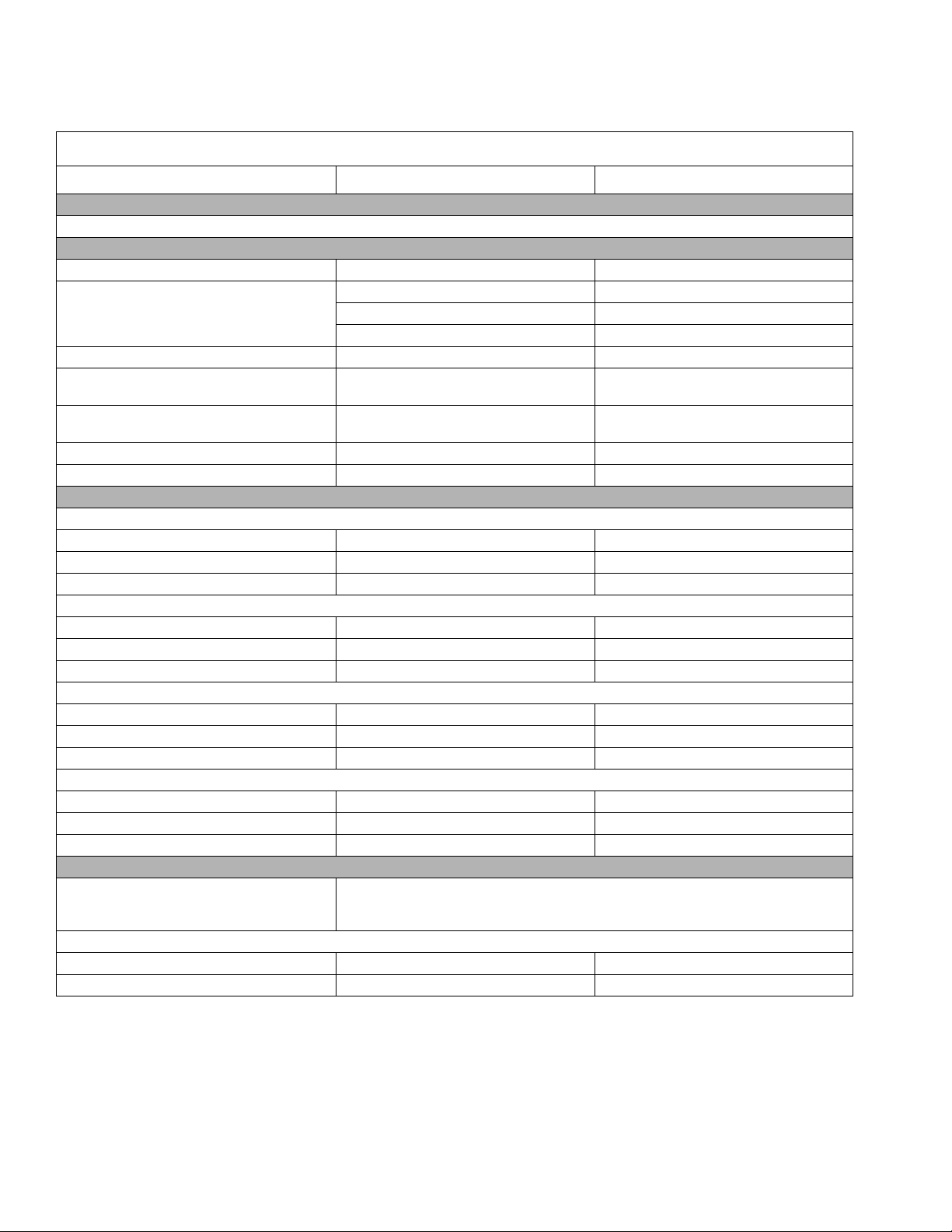
Technical Data
3900 Models
U.S. Metric
Engine
Honda GX120 Engine
Sprayer
Maximum Working Pressure 3300 psi 228 bar, 22.8 MPa
1 Gun with 0.036 in. tip 1 Gun with 0.036 in. tip
Maximum Tip Size:
Maximum Delivery Rating 1.25 gpm 4.73 lpm
Inlet Paint Strainer
Outlet Paint Filter
Pump Inlet Size 1-5/16-12 UN-2A 1-5/16-12 UN-2A
Fluid Outlet Size 1/4 npsm from fluid filter 1/4 npsm from fluid filter
Dimensions
Weight:
GMAX 3900 Standard 106 lb 48.2 kg
GMAX 3900 Lo-Boy 123 lb 55.9 kg
GMAX 3900 ProContractor 133 lb 60.5 kg
Height:
GMAX 3900 Standard 40.8 in. 103.6 cm
GMAX 3900 Lo-Boy 26.4 in. 67.1 cm
GMAX 3900 ProContractor 38.3 in. 97.3 cm
Length:
GMAX 3900 Standard 38.3 in. 97.3 cm
GMAX 3900 Lo-Boy 46.9 in. 119.1 cm
GMAX 3900 ProContractor 32.3 in. 82.0 cm
Width:
GMAX 3900 Standard 22.3 in. 56.6 cm
GMAX 3900 Lo-Boy 24.4 in. 62.0 cm
GMAX 3900 ProContractor 22.3 in. 56.6 cm
2 Guns with 0.023 in. tip 2 Guns with 0.023 in. tip
3 Guns with 0.018 in. tip 3 Guns with 0.018 in. tip
8 mesh (2589 micron)
stainless steel screen, reusable
60 mesh (250 micron)
stainless steel screen, reusable
8 mesh (2589 micron)
stainless steel screen, reusable
60 mesh (250 micron)
stainless steel screen, reusable
zinc- and nickel-plated carbon steel, PTFE, nylon, polyurethane, UHMW,
Wetted parts
Noise Level:
Sound Power 105 dBa per ISO 3744 105 dBa per ISO 3744
Sound Pressure 96 dBa measured at 3.1 ft 96 dBa measured at 1 m
fluoroelastomer, acetal, leather, aluminum, tungsten carbide,
stainless steel, chrome plating
42 3A6400A
Page 43
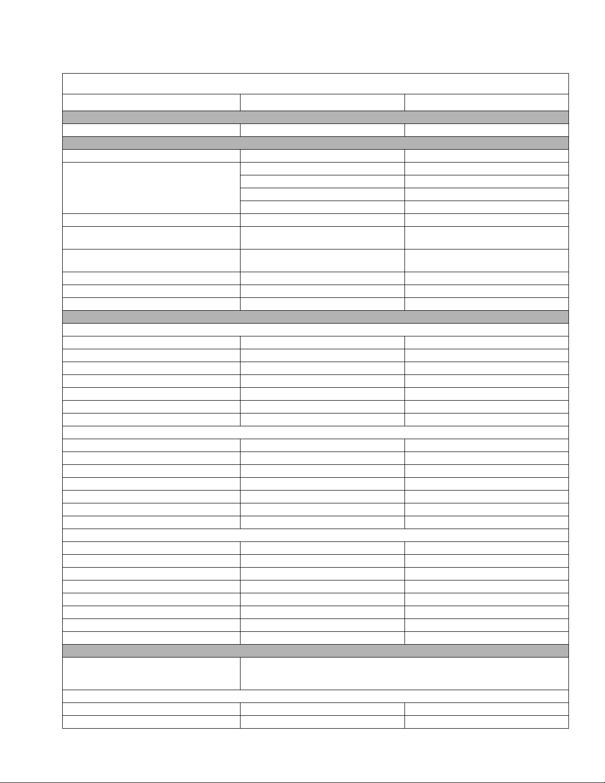
5900 Models
U.S. Metric
Engine
Honda GX160 Engine
Sprayer
Maximum Working Pressure 3300 psi 228 bar, 22.8 MPa
1 Gun with 0.043 in. tip 1 Gun with 0.043 in. tip
Maximum Tip Size:
Maximum Delivery Rating 1.6 gpm 6.06 lpm
Inlet Paint Strainer
Outlet Paint Filter
Pump Inlet Size 1-5/16-12 UN-2A 1-5/16-12 UN-2A
Fluid Outlet Size 1/4 npsm from fluid filter 1/4 npsm from fluid filter
Fluid Outlet Size (5900 IronMan and 5900HD) 3/8 npsm from fluid filter 3/8 npsm from fluid filter
Dimensions
Weight:
GMAX 5900 Standard 138 lb 62.7 kg
GMAX 5900 Lo-Boy 144 lb 65.5 kg
GMAX 5900 ProContractor 160 lb 72.7 kg
GMAX 5900 Convertible, Standard 167 lb 75.9 kg
GMAX 5900 IronMan 147 lb 67.1 kg
TexSpray 5900HD ProContractor 164 lb 74.5 kg
TexSpray 5900HD Standard 142 lb 64.5 kg
Height:
GMAX 5900 Standard 40.5 in. 102.9 cm
GMAX 5900 Lo-Boy 27.2 in. 69.1 cm
GMAX 5900 ProContractor 38.0 in. 96.5 cm
GMAX 5900 Convertible, Standard 43.8 in. 111.3 cm
GMAX 5900 IronMan 40.5 in. 102.9 cm
TexSpray 5900HD ProContractor 38.0 in. 98.6 cm
TexSpray 5900HD Standard 40.5 in. 102.9 cm
Length:
GMAX 5900 Standard 37.7 in. 95.8 cm
GMAX 5900 Lo-Boy 46.9 in. 119.1 cm
GMAX 5900 ProContractor 32.7 in. 83.1 cm
GMAX 5900 Convertible, Standard 33.0 in. 83.8 cm
GMAX 5900 IronMan 37.7 in. 95.8 cm
TexSpray 5900HD ProContractor 32.7 in. 83.1 cm
TexSpray 5900HD Standard 37.7 in. 95.8 cm
Width: 24.4 in. 62.0 cm
2 Guns with 0.029 in. tip 2 Guns with 0.029 in. tip
3 Guns with 0.023 in. tip 3 Guns with 0.023 in. tip
4 Guns with 0.019 in. tip 4 Guns with 0.019 in. tip
8 mesh (2589 micron)
stainless steel screen, reusable
60 mesh (250 micron)
stainless steel screen, reusable
8 mesh (2589 micron)
stainless steel screen, reusable
60 mesh (250 micron)
stainless steel screen, reusable
Technical Data
Wetted parts
Noise Level:
Sound Power 105 dBa per ISO 3744 105 dBa per ISO 3744
Sound Pressure 96 dBa measured at 3.1 ft 96 dBa measured at 1 m
zinc- and nickel-plated carbon steel, PTFE, nylon, polyurethane, UHMW,
fluoroelastomer, acetal, leather, aluminum, tungsten carbide,
stainless steel, chrome plating
3A6400A 43
Page 44
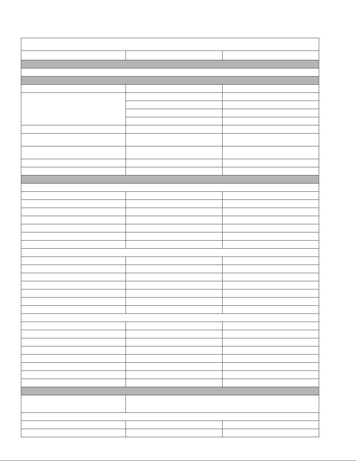
Technical Data
7900 Models
U.S. Metric
Engine
Honda GX200 Engine
Sprayer
Maximum Working Pressure 3300 psi 228 bar, 22.8 MPa
1 Gun with 0.048 in. tip 1 Gun with 0.048 in. tip
Maximum Tip Size:
Maximum Delivery Rating 2.2 gpm 8.33 lpm
Inlet Paint Strainer
Outlet Paint Filter
Pump Inlet Size 1-5/16-12 UN-2A 1-5/16-12 UN-2A
Fluid Outlet Size 3/8 npsm from fluid filter 3/8 npsm from fluid filter
Dimensions
Weight:
GMAX 7900 Standard 148 lb 67.3 kg
GMAX 7900 Lo-Boy 154 lb 70.0 kg
GMAX 7900 ProContractor 167 lb 75.9 kg
GMAX 7900 IronMan 157 lb 71.2 kg
TexSpray 7900HD Pro 182 lb 82.7 kg
TexSpray 7900HD Standard 153 lb 69.5 kg
TexSpray 7900HD IronMan 162 lb 73.5 kg
Height:
GMAX 7900 Standard 40.5 in. 102.9 cm
GMAX 7900 Lo-Boy 27.2 in. 69.1 cm
GMAX 7900 ProContractor 38.0 in. 96.5 cm
GMAX 7900 IronMan 40.5 in. 102.9 cm
TexSpray 7900HD Pro 38.0 in. 96.5 cm
TexSpray 7900HD Standard 40.5 in. 102.9 cm
TexSpray 7900HD IronMan 40.5 in. 102.9 cm
Length:
GMAX 7900 Standard 38.1 in. 96.8 cm
GMAX 7900 Lo-Boy 46.9 in. 119.1 cm
GMAX 7900 ProContractor 33.3 in. 84.6 cm
GMAX 7900 IronMan 38.1 in. 96.8 cm
TexSpray 7900HD Pro 33.3 in. 84.6 cm
TexSpray 7900HD Standard 38.1 in. 96.8 cm
TexSpray 7900HD IronMan 38.1 in. 96.8 cm
Width: 24.4 in. 62.0 cm
2 Guns with 0.035 in. tip 2 Guns with 0.035 in. tip
3 Guns with 0.027 in. tip 3 Guns with 0.027 in. tip
4 Guns with 0.023 in. tip 4 Guns with 0.023 in. tip
8 mesh (2589 micron)
stainless steel screen, reusable
60 mesh (250 micron)
stainless steel screen, reusable
8 mesh (2589 micron)
stainless steel screen, reusable
60 mesh (250 micron)
stainless steel screen, reusable
Wetted parts
Noise Level:
Sound Power 105 dBa per ISO 3744 105 dBa per ISO 3744
Sound Pressure 96 dBa measured at 3.1 ft 96 dBa measured at 1 m
zinc- and nickel-plated carbon steel, PTFE, nylon, polyurethane, UHMW,
fluoroelastomer, acetal, leather, aluminum, tungsten carbide,
stainless steel, chrome plating
44 3A6400A
Page 45

Graco Standard Warranty
Graco Standard Warranty
Graco warrants all equipment referenced in this document which is manufactured by Graco and bearing its name to be free from defects in
material and workmanship on the date of sale to the original purchaser for use. With the exception of any special, extended, or limited warranty
published by Graco, Graco will, for a period of twelve months from the date of sale, repair or replace any part of the equipment determined by
Graco to be defective. This warranty applies only when the equipment is installed, operated and maintained in accordance with Graco’s written
recommendations.
This warranty does not cover, and Graco shall not be liable for general wear and tear, or any malfunction, damage or wear caused by faulty
installation, misapplication, abrasion, corrosion, inadequate or improper maintenance, negligence, accident, tampering, or substitution of
non-Graco component parts. Nor shall Graco be liable for malfunction, damage or wear caused by the incompatibility of Graco equipment with
structures, accessories, equipment or materials not supplied by Graco, or the improper design, manufacture, installation, operation or
maintenance of structures, accessories, equipment or materials not supplied by Graco.
This warranty is conditioned upon the prepaid return of the equipment claimed to be defective to an authorized Graco distributor for verification of
the claimed defect. If the claimed defect is verified, Graco will repair or replace free of charge any defective parts. The equipment will be returned
to the original purchaser transportation prepaid. If inspection of the equipment does not disclose any defect in material or workmanship, repairs
will be made at a reasonable charge, which charges may include the costs of parts, labor, and transportation.
THIS WARRANTY IS EXCLUSIVE, AND IS IN LIEU OF ANY OTHER WARRANTIES, EXPRESS OR IMPLIED, INCLUDING BUT NOT
LIMITED TO WARRANTY OF MERCHANTABILITY OR WARRANTY OF FITNESS FOR A PARTICULAR PURPOSE.
Graco’s sole obligation and buyer’s sole remedy for any breach of warranty shall be as set forth above. The buyer agrees that no other remedy
(including, but not limited to, incidental or consequential damages for lost profits, lost sales, injury to person or property, or any other incidental or
consequential loss) shall be available. Any action for breach of warranty must be brought within two (2) years of the date of sale.
GRACO MAKES NO WARRANTY, AND DISCLAIMS ALL IMPLIED WARRANTIES OF MERCHANTABILITY AND FITNESS FOR A
PARTICULAR PURPOSE, IN CONNECTION WITH ACCESSORIES, EQUIPMENT, MATERIALS OR COMPONENTS SOLD BUT NOT
MANUFACTURED BY GRACO. These items sold, but not manufactured by Graco (such as electric motors, switches, hose, etc.), are subject to
the warranty, if any, of their manufacturer. Graco will provide purchaser with reasonable assistance in making any claim for breach of these
warranties.
In no event will Graco be liable for indirect, incidental, special or consequential damages resulting from Graco supplying equipment hereunder, or
the furnishing, performance, or use of any products or other goods sold hereto, whether due to a breach of contract, breach of warranty, the
negligence of Graco, or otherwise.
FOR GRACO CANADA CUSTOMERS
The Parties acknowledge that they have required that the present document, as well as all documents, notices and legal proceedings entered into,
given or instituted pursuant hereto or relating directly or indirectly hereto, be drawn up in English. Les parties reconnaissent avoir convenu que la
rédaction du présente document sera en Anglais, ainsi que tous documents, avis et procédures judiciaires exécutés, donnés ou intentés, à la suite
de ou en rapport, directement ou indirectement, avec les procédures concernées.
3A6400A 45
Page 46

Graco Information
For the latest information about Graco products, visit www.graco.com.
For patent information, see www.graco.com/patents.
TO PLACE AN ORDER, contact your Graco distributor or call 1-800-690-2894 to identify the nearest distributor.
All written and visual data contained in this document reflects the latest product information available at the time of publication.
GRACO INC. AND SUBSIDIARIES • P.O. BOX 1441 • MINNEAPOLIS MN 55440-1441 • USA
Copyright 2018, Graco Inc. All Graco manufacturing locations are registered to ISO 9001.
Graco reserves the right to make changes at any time without notice.
Original instructions. This manual contains English. MM 3A6400
International Offices: Belgium, China, Japan, Korea
Graco Headquarters: Minneapolis
www.graco.com
Revision A,
October 2018
 Loading...