

Page 1
INSTRUCTIONS-PARTS LIST
This manual contains IMPORTANT
WARNINGS
READ
AND INSTRUCTIONS
AND
RETAIN
FOR
REFERENCE
0
GRACO
SUPPLEMENTARY 1,NFORMATION
308-1
04
Rev
A
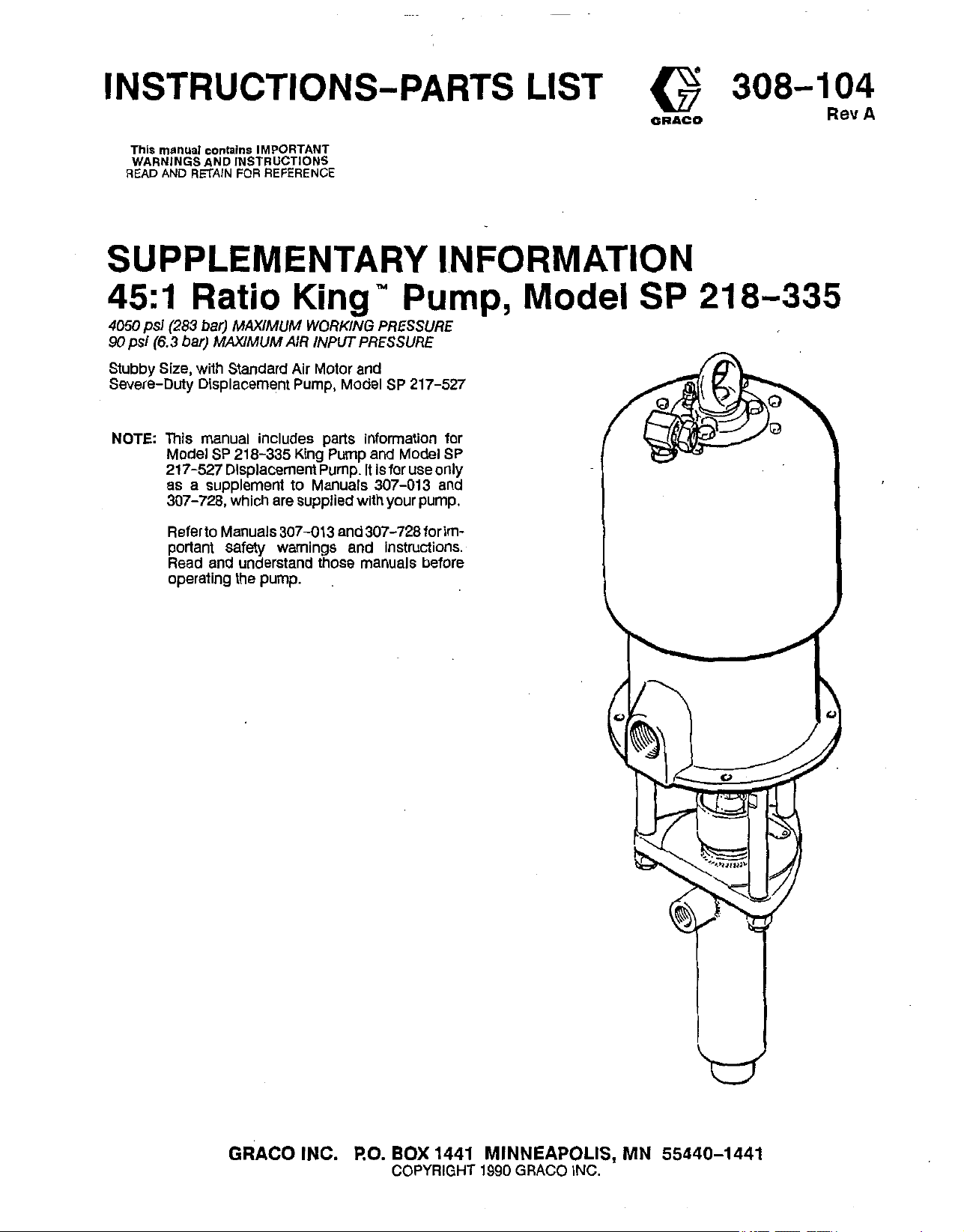
45:l
4050
psi
90
psi
Stubby Size, with Standard Air Motor and
Severe-Duty Displacement Pump, Model
NOTE
Ratio
(283 bar)
(6.3
bar)
This manual includes parts information for
Model SP 218-335 King Pump and Model SP
217-527 Displacement Pump.
as a supplement
307-728, which are supplied with your pump.
Referto Manuals307-013 and307-728forimportant safety warnings and instructions.
Read and understand those manuals before
operating the pump.
MAXIMUM
MAXIMUM
King"
WORKING PRESSURE
AIR INPUT PRESSURE
to
Manuals 307-013 and
It
Pump,
SP
217-527
is for use only
Model
SP
218-335
GRACO
INC.
RO.
BOX
COPYRIGHT 1990
1441 MINNEAPOLIS, MN 55440-1441
GRACO
INC.
Page 2
THIS
PTFE
MANUAL
Pressure Relief Procedure
To reduce the
fluid injection, splashing in the eyes or on the skin, or of a grounded metal pail, and trigger the gunlvalve
injury from moving parts, always follow this procedure
whenever
when installing, cleaning or changing spray tips/
nozzles, and whenever You stop spraying/disPensing.
1.
Engage the spray gun/dispensing valve safety sprayldispense again.
latch. If you suspect that the spray tiplnonle
2.
Shut off the air
3.
Close the bleed-tYPe master air valve (required in
your system).
4.
Disengage the gun/valve safety latch.
I
YOU
any
risk
shut
part
IS
FOR
USE
ONLY
AS
A
SUPPLEMENT
Read And Understand
OBSERVE ALL WARNINGS GIVEN IN THOSE INSTRUCTION MANUALS.
of serious bodily injury, including
Off
the Pump, when checking
Of
the
spray/dispensing system,
to
the pump.
All
Instruction Manuals Before Operating Equipment.
WARNING
01
TO
MANUALS
5.
Hold
a metal part of the gunhalve firmly to the side
to relieve pressure.
6.
Engage the gunlvalve safety latch.
7.
Open the drain valve (required
ing a container ready to catch the drainage.
Leave
pletely clogged,
lieved after following
loosen
and relieve pressure gradjally, ihen
pletely. Now clear the tiplnouie or
the
drain
the
tin
auard retainina nut or hose end couDlina
,
-
307-013
valve
or
that
pressure has not been fully
the
~~
AND
Open
steps above,
307-728.
in
your system), hav-
until
you
are
ready
or
hose
is
VERY
SLOWLY
loosen
hose.
com-
Lo6
to
re-
DISCONNECTING THE DISPLACEMENT PUMP
1.
Flush the pump if possible. Stop the pump at the bot-
tom
of
its
stroke. Follow tne
dure
Warnlng
2.
Disconnecttheairandfluidhoses.Removethepump
from its mounting.
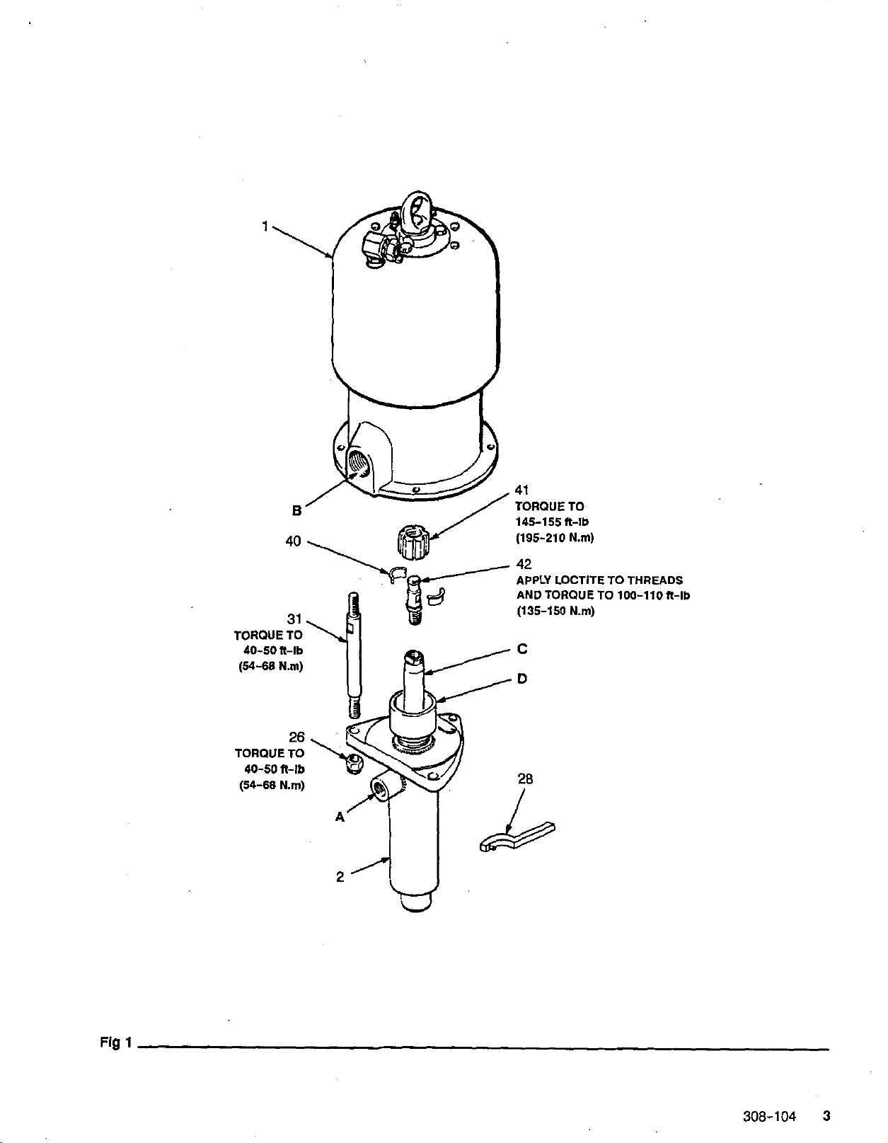
3.
See
Fig
motor piston rod.
(40)
plers
locknuts (26) from the tie rods
displacement pump
NOTE:
4.
RECONNECTING THE DISPLACEMENT PUMP
1.
2.
3.
2 308-104
Do
not remove the connecting rod
displacement rod (C) unless the displacement
rod
the connecting rod for usewitn the new displace-
ment rod.
To service
ment Pump Model SP 217-527
the air motor, refer to instruction manual
(supplied).
See Fig
ing rod
its threads before assembling it
rod
(C),
Align the pump’s fluid outlet
OUtlet
(B)
(2)
pump
Place the coupling nut
(42).
Inse!ithecouplers
above.
1.
Screw the coupling nul
Be
careful not to
as
you lower the
(2)
is
being replaced. If that is necessary, save
the
displacement pump, refer to
1.
if
it was necessary to remove the connect-
(42),
apply a removable grade
and torque
of
the air motor. Position the displacement
on
to
the tie rods
Pressure Relief Proce-
(41)
off
of the air
lose
the
two
nut.
Unscrew the tie rod
(31).
Carefully pull the
away from the air motor
(42)
from
Displace-
at right. To sewice
306-968
of
Loctitee to
to
the displacement
100-110ft-lb (135-150
(A)
to the optional fluid
(31).
(41)
onto the connecting rod
(40)
into the coupling nut
Nm).
cou-
(1).
the
(41)
from the top. Screw the coupling
motor shaft snugly. Screw the locknuts
(31)
tie rods
3.
Mount the pump
the ground wire if it was disconnected during repair.
4.
TiOhten the tie rod locknuts
46-50R-lb
to
145-155fl-lb (195-210
5.
Start the
bar) air pressure, to check the tie rods for signs of
binding. Adjustthe tie rods as necessary to eliminate
binding. Tighten the packing nut/wet-cup
wrench
the wet-cup half full with Graco Throat Seal Liquid or
compatible solvent.
DISPLACEMENT PUMP MODEL SP 217-527
Refer to the Parts Drawing and List
NOS.
in
the parts list correspond with those
307-728.
To repair Displacement Pump SP
struction Manual
there, with the following exceptions:
1.
Packing Repair Kits
enced in
stack
The
v-packings
leather, as shown
2.
The method
217-527
scribed
graphs in this Supplement for instructions.
loosely.
and
reconnect
(54-68
pump
(28)
307-728
223-480,
to
in
N.m). Toiqie the ciiupling nit
Nm).
and run
supplied,
307-728
which
of
connecting Displacement Pump SP
the air motor is different from that de-
307-728.
it
slowly, at about
so
it
is just snug -no tighter. Fill
and follow all instructionsgiven
220-395
do
not
is
used
in
this stack are one and four
on
page
Refer to the preceding para-
nut
up onto the air
(26)
all
hoses. Reconnect
(31)
evenlv. and toroue to
40
(0)
on
page
5.
in
217-527,
and
include gland/packing
in
Mod
5.
refer to In-
223-643
onto the
(41)
psi
(2.8
withthe
The
Ref.
Manual
refer-
217-527.
Page 3
TORQUE
40-50 ft-lb
(54-68
N.m)
B
40
31
TO
2
41
TORQUE
145-155 It-lb
(195-210
TO
N.m)
42
APPLY
LOCTITE
AND
TORQUETO
(135-150
N.m)
TO
THREADS
100-110It-lb
Fig
1
308-104
3
Page 4

REF
PART
NO. NO. DESCRIPTION
1
207-647
2
.
SP 217-527 DISPLACEMENT PUMP
26 101-712 NUT,
28 102-176 WRENCH
31 167-911
39 172-447"' LABEL,
40 185-336
41' 185-337
42 186-575
***Extra warnings and tags are supplied at
306
and
307
numbers in descriptions refer to separate instruc-
tion manuals, supplied.
145-155R-lb
(195-210
APPLY LOCTITE TO THREADS
AND
(135-150
N.m)
TORQUE TO
N.m)
100-110R-lb
AIR
MOTOR
See
See
ROD,
306-968
page 5 for
lock;
tie;
for
parts
5/8-11
7" (178
parts
mm),
shoulder-to-shoulder
warning
(not
shown)
COUPLERS
COUPLING NUT
ROD,
connecting
ASSY
no
charge.
QN
1
1
3
1
3
1
2
1
1
40-50
ft-lb
4
308-104
Page 5

PARTS
PTFE
PTFE
DRAWING AND
LIST
~~~~~~,~~~;~~~~~~~~
,~~,~,.~,~,,~X..,l,*x.
,,,..
,*n
Model SP
Includes
217-527
items
Dlsplacernent Pump
1-29
REF
NO. PART NO. DESCRIPTION
1
207-470 HOUSING, pump; carbon steel
2 207-471 PACKING NUThVET-CUP;
3 207-472&* PISTON carbon steel
4 207-473 HOtSING, intake valve; carbon Steel
6 102-972** BALL, stainless steel; 7/8”
7 102-973** BALL, sta teel; 1-1/4“ dia
9
106-260**
11
167-890 PIN, ball
12 167-891
13 167-892 GUIDE,
14 178-894
15 167-894” GASK
16 167495” WASHER, flat: carbon steel
22 178-888
26 172-479*’* TAG, warning (not shown)
223-480*’
29
**Recommended
duce down time.
***€ma warnings and
carbon steel 1
tun
sten carbide
with tungsten carbide seat 1
O-RING;
carbon steel 1
RETAINER; carbon steel
SLEEVE
ROD,
GUNDlPACKlNG STACK
“tool
stop,
Intakevalve;
ball;
carbon steel
stainless steel
displacement; stainless steel 1
box”
spare paiis. Keep
tags
ere supplied at no charge.
with
seat
dia.
on
hand
OTY
to
re-
1
1
1
1
1
1
1
1
1
1
1
2
APPLY
AND
TORQUE
150-175 ft-lb
TORQUE
110-125
(150-170
SEALANT
TO
4’
TO
ft-lb
N.m)
1
To
be
sure
you
accessories,
chart below.
2.
Checkthepartsl1sttoidentilythecorrectpartnumber:donotuse
the ref. no. when ordering.
3.
Order
all
6
diglt
Part Number
I
receive the correct replacement parts,
always
give
all
of
the information requested in
parts
from your nearest
QtY
I
I
Graco
Part DesCrIDllon
distributor.
.
kits
4
the
or
1
I
308-104
5
Page 6

NOTES:
6
308-104
Page 7

NOTES:
308-104
7
Page 8

Maximum
PTFE
PTFE
Air
Pump cycles per
Maximum
Air consumption approx. 38
Wened
LoctiteQ
fluid
working pressure
input pressure operating range
1
gallon
....
recommended
......................................
mrts
.............
s
a
registered trademark of the
(3.8
numn
....
--
is a registered trademark
.................................
............................
liters)
............................................
soeed
for
-,
304,440
continuous
at
1
gpm
and
17-4
omrafion ........
~~~~
(3.8
literslmin) at
PH
Grades of Stainless Steel.
70
4050
psi
20-90
50
scfm
(283 bar)
psi (1.4-6.3 bar)
cycles
,
(1.0
16
mr min
~.~~
mJImin)
psi (4.9 bar) air pressure
C
teel,
Tu~ngsten Carbide, Chrome and Zinc Plating, Leather
Du
Pont
Co.
of
the
Loctite
Corp.
WARRANTY
in
Graco warrants all equipmenl manufactured by it and bearing its name to be free from defects
ship on the date of sale by an authorized Graco distributor to the original purchaser for
use.
for breach of this warranty, Graco will, for a period of twelve months from the date of sale, repair or replace any part
material and workman-
As
purchaser’s sole remedy
of
the
equipment proven defective, This warranty applies only when the equipment is installed, operated and maintained in
accordance with Graco’s written recommydations.
Thiswarrantydoesnot cover, andGraco shall not be liablefor, any malfunction, damage orwearcaused byfauityinstallation, misapplication, abrasion, corrosion, inadequate or improper maintenance, negligence, accident, tampering, or
substitution of non-Graco component parts. Nor shall Graco be liable for malfunction, damage or wear caused by the
incompatibility with Graco equipment of structures, accessories, equipment or materials not supplied by Graco, or the
improper design, manufacture, installation, operation or maintenance of structures, accessories, equipment or materials
not.supplied by Graco.
This warranty is conditioned upon the prepaid return of the equipment claimed to be defective to an authorized Graco
distributor for verification of the claim. If the claimed defect is verified, Graco will repair or replace free of charge any
of
defective parts. The equipmentwill be returned to the original purchasertransportation prepaid. If inspection
ment does not disclose any defect
in
material or workmanship, repairs will be made at a reasonable charge, which
the equip-
charges may include the costs of parts, labor and transportation.
DISCLAIMERS AND LIMITATIONS
THETERMSOFTHlSWARRANTYCONSTl~EPURCHASER’SSOLEANDEXCUlSlVEREMEOYANDAREINLlEUOFANYOTHERWARRANTlES
(EXPRESSORIMPLIED),lNCLUDlNGWARRANTYOFMERCHANTABILITYORWARRANTYOFFlTNESSFORAPARTlCULARPURPOSE.ANDOF
ANY NON-CONTRACTUAL LIABILITIES, INCLUDING PRODUCT LIABILITIES, BASE0 ON NEGLIGENCE ORSTRICT LIABILITY. EVERY FORM OF
LIABILITY FOR DIRECT, SPECIAL
GRACO’SLlABlLlTYEXCEEDTHEAMOUNTOFTHEPURCHASEPRICE.ANYACTlONFORBREACHOFWARRANTYMUSTBEBR0UGHTWlTHIN
TWO
(2)
YEARS OF THE DATE OF SALE.
OR
CONSEQUENTIAL DAMAGES
..
OR
LOSS
IS
EXPRESSLY EXCLUDED AND DENIED. IN NO CASE SHALL
EQUIPMENT NOT COVERED BY GRACO WARRANTY
GRACO MAKES NO WARRANW, AN0 DISCLAIMS ALL IMPLIED WARRANTIES OF MERCHANTABlLrPl AND FITNESS FOR A PARTICULAR PURPOSE, WITH RESPECTTO ACCESSORIES. EQUIPMENT, MATERIALS,
items sold, but not manufactured by Graco (such as electric motor, switches, hose, etc.) are subject to the warranty,
Of
their rnantifacturer. Graco will provide purchaser with reasonable assistance in making any claim for breach of these
OR
COMPONENTSSOLD BUT NOT MANUFACTURED BY GRACO.These
if
any,
warranties.
TO
PLACEAN
call this number to identify the distributor closest to you:
ORDER,
contact your Graco distributor, or
FOR
tion or assistance regarding the application of Graco
1-800-328-021 1
Toll Free
equipment:
Factory Branches: Atlanta, Chicago, Dallas, Detroit,
TECHNICAL ASSISTANCE, service repair informa-
1-800-543-0339
Los
Angeles, West Caidwell
Toll Free
(N.J.)
Subsidiary and Affiliate Companies: Canada: England; Switzerland; France; Germany; Hong Kong; Japan
GRACO INC.
P.O. BOX
1441
PRINTED IN USA.
MINNEAPOLIS, MN
3MI-104
9-90
55440-1441
 Loading...